EP1898780B1 - Systems and methods for multi-axis cardiac vibration measurements - Google Patents
Systems and methods for multi-axis cardiac vibration measurements Download PDFInfo
- Publication number
- EP1898780B1 EP1898780B1 EP06770836.2A EP06770836A EP1898780B1 EP 1898780 B1 EP1898780 B1 EP 1898780B1 EP 06770836 A EP06770836 A EP 06770836A EP 1898780 B1 EP1898780 B1 EP 1898780B1
- Authority
- EP
- European Patent Office
- Prior art keywords
- heart sound
- heart
- operable
- axis
- axes
- Prior art date
- Legal status (The legal status is an assumption and is not a legal conclusion. Google has not performed a legal analysis and makes no representation as to the accuracy of the status listed.)
- Not-in-force
Links
Images


Classifications
-
- A—HUMAN NECESSITIES
- A61—MEDICAL OR VETERINARY SCIENCE; HYGIENE
- A61B—DIAGNOSIS; SURGERY; IDENTIFICATION
- A61B7/00—Instruments for auscultation
-
- A—HUMAN NECESSITIES
- A61—MEDICAL OR VETERINARY SCIENCE; HYGIENE
- A61B—DIAGNOSIS; SURGERY; IDENTIFICATION
- A61B7/00—Instruments for auscultation
- A61B7/02—Stethoscopes
- A61B7/04—Electric stethoscopes
Definitions
- the field generally relates to implantable medical devices and, in particular, but not by way of limitation, to systems and methods for monitoring the mechanical functions of the heart.
- Implantable medical devices are devices designed to be implanted into a patient. Some examples of these devices include cardiac function management (CFM) devices such as implantable pacemakers, implantable cardioverter defibrillators (ICDs), cardiac resynchronization devices, and devices that include a combination of such capabilities.
- CFM cardiac function management
- the devices are typically used to treat patients using electrical therapy and to aid a physician or caregiver in patient diagnosis through internal monitoring of a patient's condition.
- the devices may include electrodes in communication with sense amplifiers to monitor electrical heart activity within a patient, and often include sensors to monitor other internal patient parameters.
- Other examples of implantable medical devices include implantable insulin pumps or devices implanted to administer drugs to a patient.
- Heart sounds are associated with mechanical vibrations from activity of a patient's heart and the flow of blood through the heart. Heart sounds recur with each cardiac cycle and are separated and classified according to the activity associated with the vibration.
- the first heart sound (S1) is the vibrational sound made by the heart during tensing of the mitral valve.
- the second heart sound (S2) marks the beginning of diastole.
- the third heart sound (S3) and fourth heart sound (S4) are related to filling pressures of the left ventricle during diastole.
- a device according to the preamble of claim 1 is known from EP 1247 485 .
- One system embodiment includes a medical device which in turn includes an implantable multi-axis heart sound sensor, operable to produce, for each of at least two nonparallel axes, an electrical signal representative of at least one heart sound, the heart sound associated with mechanical activity of a patient's heart.
- the device also includes a controller circuit, coupled to the heart sound sensor, the controller circuit operable to measure components of the heart sound that respectively correspond to each of the axes.
- One method embodiment includes sensing at least one heart sound, which is representative of mechanical activity of a patient's heart, along at least two nonparallel axes, the sensing including using an implantable medical device, and measuring components of the heart sound corresponding to the axes.
- monitoring of heart sounds aids caregivers in detecting overall progression of heart disease. For example, for detection of ischemia, an increase in ventricular chamber stiffness and an increase in the degree of restrictive filling are correlated to an increase in loudness of S3 heart sounds. Conversely, because ischemia is associated with a decrease in ventricular chamber contractility, ischemia is correlated to a decrease in the loudness of the S1 heart sound.
- Implantable medical devices can include sensors to assist caregivers in monitoring internal patient parameters such as heart sounds.
- a heart sound sensor is an accelerometer monitoring heart sound vibrations along a single axis. Monitoring along only one axis may miss sensing additional heart sound information because the vibrations may radiate in multiple directions. Additionally, it is possible that heart sound information may not contain any information along the measurement axis of a single axis sensor. The present inventors have recognized a need for improved measurement of heart sounds.
- FIG. 1 illustrates an embodiment of a system 100 that uses an IMD 110.
- the system 100 shown is one embodiment of portions of a system 100 used to treat a cardiac arrhythmia or otherwise improve heart function.
- a pulse generator (PG) or other IMD 110 is coupled by a cardiac lead 108, or additional leads, to a heart 105 of a patient 102.
- Examples of IMD 110 include, without limitation, a pacer, a defibrillator, a cardiac resynchronization therapy (CRT) device, or a combination of such devices.
- System 100 also includes an IMD programmer or other external system 170 that provides wireless communication signals 160 to communicate with the IMD 110, such as by using radio frequency (RF) or other telemetry signals.
- RF radio frequency
- Cardiac lead 108 includes a proximal end that is coupled to IMD 110 and a distal end, coupled by an electrode or electrodes to one or more portions of a heart 105.
- the electrodes typically deliver cardioversion defibrillation, pacing, resynchronization therapy, or combinations thereof to at least one chamber of the heart 105.
- IMD 110 includes components that are enclosed in a hermetically-sealed canister or "can.” Additional electrodes may be located on the can, or on an insulating header, or on other portions of IMD 110, for providing unipolar pacing and/or defibrillation energy in conjunction with the electrodes disposed on or around heart 105.
- the lead 108 or leads and electrodes are also used for sensing electrical activity of a heart 105.
- Implantable heart sound sensors are generally implantable acoustic sensors that convert the detected sounds of the heart into an electrical signal representative of the heart sounds.
- an acoustic sensor for an IMD includes an accelerometer mounted within the can.
- the accelerometer monitors heart sound vibrations along a single axis. Usually, this axis is parallel to a patient's sagittal plane and perpendicular to the patient's chest. While a single axis device results in a simple implementation, the heart sound signal components measurable along axes orthogonal to the single axis of measurement may be lost.
- monitoring heart sounds along multiple axes may improve the signal-to-noise ratio of heart sound measurements. For example, adding signal components measured along different axes for a given heart sound may provide a stronger composite heart sound signal than measuring a single component along a particular axis.
- a multi-axis acoustic sensor could measure sounds, such as cardiac murmurs.
- multi-axis monitoring is believed to allow for better separation of one heart vibration from another, such as through phase angle information, direction information, and additional timing information.
- Multi-axis monitoring may also help separate left chamber heart sounds from right chamber heart sounds.
- Such multi-axis monitoring may help detect changes in the heart sounds due to cardiac synchrony or asynchrony.
- the multi-axis monitoring may also help separate heart sounds from other sounds such as coughing or speech sounds, or a patient's breathing.
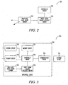
- FIG. 2 shows portions of an embodiment of a system 200 for monitoring heart sounds.
- the system 200 includes a medical device which in turn includes at least one implantable multi-axis heart sound sensor 210, a heart sound sensor interface circuit 220 coupled to the multi-axis heart sound sensor 210, and a controller circuit 230 coupled to the heart sound sensor interface circuit 220.
- the multi-axis heart sound sensor 210 is operable to produce an electrical signal representative of at least one heart sound for each of at least two nonparallel axes. Such axes are typically mutually orthogonal.
- the heart sound sensor interface circuit 220 provides signals representative of one or more heart sounds to the controller circuit 230.
- the controller circuit 230 measures the signals in relation to a physiological event, such as by synchronizing the measurement to a sensed heart depolarization.
- a physiological event such as by synchronizing the measurement to a sensed heart depolarization.
- the multi-axis heart sound sensor 210 is operable to produce first, second, and third electrical signals representative of respective directional components of the heart sound for respective orthogonal first, second, and third axes.
- the first, second, and third axes correspond to the x, y, and z axes, with the z axis perpendicular to a patient's chest.
- the controller circuit 230 is operable to measure components of the heart sound that respectively correspond to each of the respective orthogonal first, second, and third axes.
- the term "operable" refers to the controller circuit 230 executing an algorithm or algorithms implemented by hardware, software, firmware or any combination of hardware, software or firmware. In some embodiments, the measuring is performed continuously.
- the measuring is performed intermittently to conserve energy.
- the controller circuit 230 includes a clock circuit and the measuring is done contingent on a certain time of day. This allows the measurements to be made while a patient is presumably in substantially the same posture or a similar posture, such as at night while a patient presumably is inactive and lying down.
- the medical device includes a posture sensor coupled to the controller circuit 230 to determine a patient's posture when measuring the multi-axis heart sounds. Examples of posture sensors include a tilt switch and a multi-axis accelerometer.
- the heart sound sensor interface circuit 220 includes signal processing circuitry corresponding to each of the first, second, and third axes for processing the corresponding one of the first, second, and third electrical signals. This allows signal processing such as frequency-selective filtering, gain-selective amplification, or selective sensing thresholds to be used on each of the first, second, and third electronic signals.
- the filtering allows one heart sound signal to be separated from other heart sounds, or separated from other sources of sound such as breathing, or muscle movement.
- the filtering and amplification provides improvement in the signal-to-noise ratio of the measurements along each axis.
- the signal processing circuitry includes filter circuits to remove components of the electrical signals associated with breathing sounds, such as lung sounds or sounds due to a patient snoring.
- the controller circuit 230 includes a timing circuit, and removal of breathing sounds is synchronized with a time of day such as when a patient is likely to be sleeping.
- the controller circuit 230 includes an averaging circuit to accomplish signal processing of the signals, and the controller circuit 230 is operable to measure components of the heart sound from an ensemble or other average of multiple sampled values of like heart sound signals.
- the controller circuit 230 is operable to measure components of the heart sound from an ensemble ordering of multiple sampled values of like heart sound signals.
- the sampled values are sorted into either ascending or descending order.
- the value used for the measurement is the middle (median) value.
- the controller circuit 230 is operable to measure components of the heart sound from a combination of ensemble averaging and ensemble ordering of multiple sampled values of like heart sound signals. In one illustrative example, five sampled values are sorted into either ascending or descending order. The controller circuit 230 then averages the median value, the next value higher, and the next value lower than the median to determine the value used for the measurement.
- the controller circuit 230 combines the first, second, and third electrical signals together to produce a heart sound vector.
- Forming a vector of the heart sounds adds directional information to heart sound measurements.
- the additional phase angle and direction information from a heart sound vector are useful to a caregiver to assist in the management of patient heart disease.
- contractility of a heart decreases when the heart does not receive sufficient oxygen. Insufficient oxygen to the heart is often caused by a build-up of plaque in arteries that provide oxygenated blood to the heart.
- the associated increase in ventricular chamber stiffness and increase in the degree of restrictive filling are correlated to an increase in loudness of S3 heart sounds.
- Providing directional heart sound information from multi-axis monitoring may assist a caregiver in identifying the portion of a heart that has reduced contractility.
- the directional information may also be useful to discriminate other sounds from heart sounds.
- lung sounds may have a strong component along one axis that is not present along another axis.
- the controller circuit 230 deems that a condition associated with heart failure decompensation occurred when the amplitude of the 7 measured component of at least one of the heart sound signals exceeds an amplitude threshold.
- the three axes are used to define a three-dimensional threshold surface, and the controller circuit 230 deems that a condition associated with heart failure decompensation occurred when the amplitude of measured components of the heart sound signals exceeds the threshold surface.
- the multi-axis heart sound sensor 210 includes a multi-axis accelerometer. In some embodiments at least one axis of the multi-axis heart sound sensor 210 produces an electrical signal indicative of the patient's physical activity. This activity signal can be separated from the heart sound signal by signal processing (such as by filtering for example) and is useful in determining if the patient is inactive or active. In some examples, a circuit to interface to the accelerometer along the axis used to measure physical activity is different from the sensitivity of a circuit to interface to the accelerometer along the axis used to measure heart sounds.
- Different sensitivity refers to the activity sensing circuit having a different signal sensing threshold than the heart sound sensing circuit, or the activity sensing circuit providing different amplification to accelerometer signals, or the activity sensing circuit having both a different signal sensing threshold and a different amplification than the heart sound sensing circuit.
- the medical device further includes a storage circuit coupled to the controller circuit 230.
- the storage circuit is operable to store, for each of the first, second, and third axes, information representative of the measured component of the heart sound corresponding to that one of the first, second, and third axes.
- the medical device further includes a communication circuit to communicate with a second device to provide multi-axis heart sound information.
- the controller circuit 230 is operable to communicate an indication of heart failure decompensation.
- FIG. 3 shows portions of an embodiment of a system 300 for monitoring heart sounds.
- the system 300 includes an implantable device 305 and an external device 310 operable to communicate with the implantable device 305.
- the implantable device 305 includes a multi-axis heart sound sensor 325 and a heart sound sensor interface circuit 320 coupled to a controller circuit 330.
- the multi-axis heart sound sensor 325 produces electrical signals representative of at least one heart sound for each of at least two nonparallel axes, such as at least two orthogonal axes.
- the controller circuit 330 is operable to measure the heart sound signal from each of the axes.
- the implantable device 305 also includes a memory circuit 335, a sensing circuit 340, and a therapy circuit 345.
- the memory circuit 335 stores heart sound measurements.
- the sensing circuit 340 is coupled to a cardiac lead or leads to sense one or more cardiac signals from a subject's heart.
- the controller circuit 330 is operable to measure the heart sounds in correspondence with a sensed heart depolarization to aid in the identification of heart sounds.
- the heart sound signal is identified by alignment of heart sound signals to a known artifact in a sensed cardiac signal. For example, a sensed P-wave on the sensing circuit 340 helps align S1 and S2 heart sounds sensed with the multi-axis heart sound sensor 325.
- the therapy circuit 345 is attached to a cardiac lead or leads such as to provide cardioversion, defibrillation, pacing, resynchronization therapy, or one or more combinations thereof to at least one chamber of the heart.
- the implantable device 305 further includes a communication circuit 350.
- the external device 310 communicates wirelessly with the implantable device 305 by using radio frequency (RF) or other telemetry signals.
- the implantable device 305 communicates multi-axis heart sound information to the external device 310.
- the external device 310 is part of, or is in communication with, a computer network such as a hospital computer network or the internet.
- the external device 310 may be wired to the computer network or may communicate with the network wirelessly.
- the external device 310 includes a display operable to display multi-axis heart sound information in relation to at least one of the axes.
- the external device is operable to display at least one representation of cardiac vibrations in three dimensional space.
- FIG. 4A shows a three dimensional display 400 of a vector for a heart sound. Heart sound signals measured along the anterior-posterior (A-P) axis, the lateral-medial (L-M) axis, and the superior-inferior (S-I) axis are combined to create the vector. Well known trigonometric methods may be used to convert the vector display to magnitude and angle form.
- the external device 310 is operable to display trending over time of multi-axis heart sound information.
- the trending information is useful to establish a trend indicative of a disease status of a patient or subject. This status can be an indication of worsening status or improving status.
- FIG. 4B shows a display 410 of trending of a magnitude of a heart sound vector
- the analyses are combined with one or more measurements of one or more other physiologic sensors to form a single decision as to whether to generate an alarm. For example, trending of the heart sound vector magnitude, such as displayed in FIG.
- the medical device 305 includes signal processing circuitry corresponding to each of the first, second, and third axes for processing the corresponding one of the first, second, and third electrical signals.
- multi-axis heart sound information is transmitted to the external device 310 and the external device 310 is operable to perform signal processing on the information and display the processed heart sound information.
- the external device 310 is operable to perform noise rejection signal processing, such as frequency filtering or amplification, selectively along the individual axes.
- FIG. 5 shows a block diagram of an embodiment of a method 500 for monitoring heart sounds.
- at least one heart sound is sensed that is representative of mechanical activity of a patient's heart.
- the heart sound includes at least one of the S1 through S4 heart sound.
- the heart sound is measured along at least two nonparallel axes (such as at least two orthogonal axes) and the sensing includes sensing using an implantable device.
- directional components of the heart sound corresponding to the axes are measured.
- sensing at least one heart sound includes sensing first, second, and third electrical signals representative of respective directional components of the heart sound for respective orthogonal first, second, and third axes.
- the method 500 further includes combining the first, second, and third electrical signals to determine a heart sound vector.
- the method further includes sensing a heart depolarization event using an implantable cardiac signal sensing circuit, and measuring the heart sound includes measuring the heart sound in correspondence with a sensed heart depolarization event.
- the method 500 further includes communicating information about the first, second, and third electrical signals to an external device.
- the external device is a programmer for the implantable device.
- the external device is in communication with a computer network.
- the external device can be either wired to the computer network or is a device that communicates wirelessly with the network.
- the external device can be a repeating device that communicates with the implantable device over short distances, such as within the same room as a patient for example. The repeating device may then transmit information received from the device to the computer network.
- the repeating device can communicate wirelessly to the network such as by using a Wireless LAN for example, or over a communication network such as a mobile telephone network.
- the external device includes a display and the method 500 further includes displaying information about the components of the multi-axis heart sound measurement on the external device.
- displaying includes displaying the information in a representation of three dimensional space.
- displaying includes displaying the information over time in correspondence with other physiological measurements of a patient.
- the physiological measurements include, among others, contractility of a heart displayed as a rate of change in heart chamber pressure, patient breathing volume, and heart depolarization measured by a cardiac signal sensing circuit.
- the method 500 further includes storing trending information about the components of the heart sound, and displaying includes displaying the trending information.
- the method 500 further includes predicting heart failure decompensation of the patient using the measured components of the heart sound.
- a prediction of heart failure decompensation is made from a measured increase in the amplitude of the S3 heart sound.
- the implantable medical device deems that heart failure decompensation occurs when the amplitude of the S3 heart sound exceeds an amplitude threshold.
- the method 500 includes providing an indication of the heart failure decompensation.
- the indication is alarm, such as a buzzer or other audible indication, that heart failure decompensation occurred.
- the indication is communicated to an external device.
- the external device is an IMD programmer and the IMD indicates that heart failure decompensation occurred by setting a status indication readable by the programmer upon a subsequent interrogation of the IMD.
- FIG. 6 shows a block diagram of another embodiment of a method 600 for monitoring heart sounds.
- the method 600 is similar to the method in FIG. 5 except that at 620, the heart sound components are measured when a patient's heart rate is below a predetermined heart rate threshold value.
- the heart rate is monitored using an implantable cardiac signal sensing circuit or by monitoring the rate of occurrence of the heart sound itself.
- measuring the heart sound includes measuring the heart sound according to the time of day. This allows the measurement to be taken during a time of day while the patient is likely to be resting. Measuring according to the time of day also has the advantage of taking measurements intermittently rather than continuously in order to conserve energy used by an implantable device.
- FIG. 7 shows a block diagram of another embodiment of a method 700 for monitoring heart sounds.
- the method 700 is similar to the method in FIG. 5 except that at 720, a posture of the patient of the patient is determined.
- the components of the heart sound are measured contingent on, or corresponding to, a specified posture.
- the posture is inferred from a time of day which is determined by a clock circuit.
- a posture determination is made using a posture sensor such as a tilt switch or multi-axis accelerometer.
- a multi-axis accelerometer is used to both determine posture and sense heart sounds. Filtering or signal processing can be used to separate the electrical signal components due to movement from the electrical signal components due to heart sounds.
- the additional phase angle information, direction information, and timing information from multi-axis monitoring of heart sounds provides useful information to a caregiver to assist in the management of patient heart disease.
- Multi-axis heart sound monitoring may also assist in placement of electrodes that are part of a cardiac signal sensing circuit. Improper or ineffective electrode placement would be manifested by low contractility shown by the measured heart sounds. Properly placing the electrodes would then be manifested by increased contractility as indicated by the heart sounds.
- inventive subject matter may be referred to herein, individually and/or collectively, by the term "invention" merely for convenience and without intending to voluntarily limit the scope of this application to any single invention or inventive concept if more than one is in fact disclosed.
- inventive subject matter may be referred to herein, individually and/or collectively, by the term "invention" merely for convenience and without intending to voluntarily limit the scope of this application to any single invention or inventive concept if more than one is in fact disclosed.
- inventive subject matter merely for convenience and without intending to voluntarily limit the scope of this application to any single invention or inventive concept if more than one is in fact disclosed.
Description
- The field generally relates to implantable medical devices and, in particular, but not by way of limitation, to systems and methods for monitoring the mechanical functions of the heart.
- Implantable medical devices (IMDs) are devices designed to be implanted into a patient. Some examples of these devices include cardiac function management (CFM) devices such as implantable pacemakers, implantable cardioverter defibrillators (ICDs), cardiac resynchronization devices, and devices that include a combination of such capabilities. The devices are typically used to treat patients using electrical therapy and to aid a physician or caregiver in patient diagnosis through internal monitoring of a patient's condition. The devices may include electrodes in communication with sense amplifiers to monitor electrical heart activity within a patient, and often include sensors to monitor other internal patient parameters. Other examples of implantable medical devices include implantable insulin pumps or devices implanted to administer drugs to a patient.
- Heart sounds are associated with mechanical vibrations from activity of a patient's heart and the flow of blood through the heart. Heart sounds recur with each cardiac cycle and are separated and classified according to the activity associated with the vibration. The first heart sound (S1) is the vibrational sound made by the heart during tensing of the mitral valve. The second heart sound (S2) marks the beginning of diastole. The third heart sound (S3) and fourth heart sound (S4) are related to filling pressures of the left ventricle during diastole.
- A device according to the preamble of
claim 1 is known fromEP 1247 485 . - The invention is defined in
claim 1. Methods disclosed hereinafter are not part of the scope of the invention. - This document discusses, among other things, systems and methods for monitoring heart sounds. One system embodiment includes a medical device which in turn includes an implantable multi-axis heart sound sensor, operable to produce, for each of at least two nonparallel axes, an electrical signal representative of at least one heart sound, the heart sound associated with mechanical activity of a patient's heart. The device also includes a controller circuit, coupled to the heart sound sensor, the controller circuit operable to measure components of the heart sound that respectively correspond to each of the axes.
- One method embodiment includes sensing at least one heart sound, which is representative of mechanical activity of a patient's heart, along at least two nonparallel axes, the sensing including using an implantable medical device, and measuring components of the heart sound corresponding to the axes.
- This summary is intended to provide an overview of the subject matter of the present patent application. It is not intended to provide an exclusive or exhaustive explanation of the invention. The detailed description is included to provide further information about the subject matter of the present patent application.
-
-
FIG. 1 illustrates an embodiment of a system that uses an implantable medical device. -
FIG. 2 shows portions of an embodiment of a system for monitoring heart sounds.
European Patent ApplicationEP 1247485 A1 concerns an apparatus for continuously monitoring a blood pressure of a subject; the apparatus comprises means for extracting, from a pressure-pulse-wave signal, a heart sound component representing heart sounds. -
FIG. 3 shows portions of an embodiment of a system for monitoring heart sounds. -
FIG. 4A shows a three dimensional display of a vector for a heart sound. -
FIG. 4B shows a display of trending of a magnitude of a heart sound vector over time. -
FIG. 5 shows a block diagram of an embodiment of a method for monitoring heart sounds. -
FIG. 6 shows a block diagram of an embodiment of a method for monitoring heart sounds. -
FIG. 7 shows a block diagram of an embodiment of a method for monitoring heart sounds. - In the following detailed description, reference is made to the accompanying drawings which form a part hereof, and specific embodiments in which the invention may be practiced are shown by way of illustration. It is to be understood that other embodiments may be used and structural or logical changes may be made without departing from the scope of the present invention.
- Monitoring of heart sounds aids caregivers in detecting overall progression of heart disease. For example, for detection of ischemia, an increase in ventricular chamber stiffness and an increase in the degree of restrictive filling are correlated to an increase in loudness of S3 heart sounds. Conversely, because ischemia is associated with a decrease in ventricular chamber contractility, ischemia is correlated to a decrease in the loudness of the S1 heart sound.
- Implantable medical devices (IMDs) can include sensors to assist caregivers in monitoring internal patient parameters such as heart sounds. Typically, a heart sound sensor is an accelerometer monitoring heart sound vibrations along a single axis. Monitoring along only one axis may miss sensing additional heart sound information because the vibrations may radiate in multiple directions. Additionally, it is possible that heart sound information may not contain any information along the measurement axis of a single axis sensor. The present inventors have recognized a need for improved measurement of heart sounds.
- The present application discusses, among other things, systems and methods for monitoring heart sounds.
FIG. 1 illustrates an embodiment of asystem 100 that uses an IMD 110. Thesystem 100 shown is one embodiment of portions of asystem 100 used to treat a cardiac arrhythmia or otherwise improve heart function. A pulse generator (PG) orother IMD 110 is coupled by acardiac lead 108, or additional leads, to aheart 105 of apatient 102. Examples of IMD 110 include, without limitation, a pacer, a defibrillator, a cardiac resynchronization therapy (CRT) device, or a combination of such devices.System 100 also includes an IMD programmer or otherexternal system 170 that provideswireless communication signals 160 to communicate with theIMD 110, such as by using radio frequency (RF) or other telemetry signals. -
Cardiac lead 108 includes a proximal end that is coupled toIMD 110 and a distal end, coupled by an electrode or electrodes to one or more portions of aheart 105. The electrodes typically deliver cardioversion defibrillation, pacing, resynchronization therapy, or combinations thereof to at least one chamber of theheart 105. IMD 110 includes components that are enclosed in a hermetically-sealed canister or "can." Additional electrodes may be located on the can, or on an insulating header, or on other portions ofIMD 110, for providing unipolar pacing and/or defibrillation energy in conjunction with the electrodes disposed on or aroundheart 105. Thelead 108 or leads and electrodes are also used for sensing electrical activity of aheart 105. - Implantable heart sound sensors are generally implantable acoustic sensors that convert the detected sounds of the heart into an electrical signal representative of the heart sounds. Typically, an acoustic sensor for an IMD includes an accelerometer mounted within the can. The accelerometer monitors heart sound vibrations along a single axis. Usually, this axis is parallel to a patient's sagittal plane and perpendicular to the patient's chest. While a single axis device results in a simple implementation, the heart sound signal components measurable along axes orthogonal to the single axis of measurement may be lost. Because heart sound vibrations along one axis may be more pronounced along a second axis, monitoring heart sounds along multiple axes may improve the signal-to-noise ratio of heart sound measurements. For example, adding signal components measured along different axes for a given heart sound may provide a stronger composite heart sound signal than measuring a single component along a particular axis. In addition to measuring heart sounds, a multi-axis acoustic sensor could measure sounds, such as cardiac murmurs.
- Additionally, monitoring heart sounds along multiple axes increases the amount of useful information available for interpretation by caregivers. For example, multi-axis monitoring is believed to allow for better separation of one heart vibration from another, such as through phase angle information, direction information, and additional timing information. Multi-axis monitoring may also help separate left chamber heart sounds from right chamber heart sounds. Such multi-axis monitoring may help detect changes in the heart sounds due to cardiac synchrony or asynchrony. The multi-axis monitoring may also help separate heart sounds from other sounds such as coughing or speech sounds, or a patient's breathing.
-
FIG. 2 shows portions of an embodiment of asystem 200 for monitoring heart sounds. Thesystem 200 includes a medical device which in turn includes at least one implantable multi-axisheart sound sensor 210, a heart soundsensor interface circuit 220 coupled to the multi-axisheart sound sensor 210, and acontroller circuit 230 coupled to the heart soundsensor interface circuit 220. The multi-axisheart sound sensor 210 is operable to produce an electrical signal representative of at least one heart sound for each of at least two nonparallel axes. Such axes are typically mutually orthogonal. The heart soundsensor interface circuit 220 provides signals representative of one or more heart sounds to thecontroller circuit 230. In one example, thecontroller circuit 230 measures the signals in relation to a physiological event, such as by synchronizing the measurement to a sensed heart depolarization. An example of making heart sound measurements in relation to a heart depolarization is found inU.S. Patent Application Ser. No. 10/334,694 entitled, "Method and Apparatus for Monitoring of Diastolic Hemodynamics," which is hereby incorporated by reference. - In some examples, the multi-axis
heart sound sensor 210 is operable to produce first, second, and third electrical signals representative of respective directional components of the heart sound for respective orthogonal first, second, and third axes. In an example, the first, second, and third axes correspond to the x, y, and z axes, with the z axis perpendicular to a patient's chest. Thecontroller circuit 230 is operable to measure components of the heart sound that respectively correspond to each of the respective orthogonal first, second, and third axes. The term "operable" refers to thecontroller circuit 230 executing an algorithm or algorithms implemented by hardware, software, firmware or any combination of hardware, software or firmware. In some embodiments, the measuring is performed continuously. In some embodiments, the measuring is performed intermittently to conserve energy. In some embodiments, thecontroller circuit 230 includes a clock circuit and the measuring is done contingent on a certain time of day. This allows the measurements to be made while a patient is presumably in substantially the same posture or a similar posture, such as at night while a patient presumably is inactive and lying down. In some embodiments, the medical device includes a posture sensor coupled to thecontroller circuit 230 to determine a patient's posture when measuring the multi-axis heart sounds. Examples of posture sensors include a tilt switch and a multi-axis accelerometer. - In some examples, the heart sound
sensor interface circuit 220 includes signal processing circuitry corresponding to each of the first, second, and third axes for processing the corresponding one of the first, second, and third electrical signals. This allows signal processing such as frequency-selective filtering, gain-selective amplification, or selective sensing thresholds to be used on each of the first, second, and third electronic signals. The filtering allows one heart sound signal to be separated from other heart sounds, or separated from other sources of sound such as breathing, or muscle movement. The filtering and amplification provides improvement in the signal-to-noise ratio of the measurements along each axis. In some examples, the signal processing circuitry includes filter circuits to remove components of the electrical signals associated with breathing sounds, such as lung sounds or sounds due to a patient snoring. In some examples, thecontroller circuit 230 includes a timing circuit, and removal of breathing sounds is synchronized with a time of day such as when a patient is likely to be sleeping. - In some examples, the
controller circuit 230 includes an averaging circuit to accomplish signal processing of the signals, and thecontroller circuit 230 is operable to measure components of the heart sound from an ensemble or other average of multiple sampled values of like heart sound signals. One example of descriptions of systems and methods for obtaining ensemble averages of heart sound signals is found in the commonly assigned, co-pendingU.S. Pat. Appl. Serial No. 10/746,874 by Siejko et al. controller circuit 230 is operable to measure components of the heart sound from an ensemble ordering of multiple sampled values of like heart sound signals. In ensemble ordering, the sampled values are sorted into either ascending or descending order. The value used for the measurement is the middle (median) value. In some examples, thecontroller circuit 230 is operable to measure components of the heart sound from a combination of ensemble averaging and ensemble ordering of multiple sampled values of like heart sound signals. In one illustrative example, five sampled values are sorted into either ascending or descending order. Thecontroller circuit 230 then averages the median value, the next value higher, and the next value lower than the median to determine the value used for the measurement. - In some embodiments, the
controller circuit 230 combines the first, second, and third electrical signals together to produce a heart sound vector. Forming a vector of the heart sounds adds directional information to heart sound measurements. The additional phase angle and direction information from a heart sound vector are useful to a caregiver to assist in the management of patient heart disease. For patients with ischemia, contractility of a heart decreases when the heart does not receive sufficient oxygen. Insufficient oxygen to the heart is often caused by a build-up of plaque in arteries that provide oxygenated blood to the heart. The associated increase in ventricular chamber stiffness and increase in the degree of restrictive filling are correlated to an increase in loudness of S3 heart sounds. Providing directional heart sound information from multi-axis monitoring may assist a caregiver in identifying the portion of a heart that has reduced contractility. The directional information may also be useful to discriminate other sounds from heart sounds. For example, lung sounds may have a strong component along one axis that is not present along another axis. - In some examples, the
controller circuit 230 deems that a condition associated with heart failure decompensation occurred when the amplitude of the 7 measured component of at least one of the heart sound signals exceeds an amplitude threshold. In some examples, the three axes are used to define a three-dimensional threshold surface, and thecontroller circuit 230 deems that a condition associated with heart failure decompensation occurred when the amplitude of measured components of the heart sound signals exceeds the threshold surface. - In some embodiments, the multi-axis
heart sound sensor 210 includes a multi-axis accelerometer. In some embodiments at least one axis of the multi-axisheart sound sensor 210 produces an electrical signal indicative of the patient's physical activity. This activity signal can be separated from the heart sound signal by signal processing (such as by filtering for example) and is useful in determining if the patient is inactive or active. In some examples, a circuit to interface to the accelerometer along the axis used to measure physical activity is different from the sensitivity of a circuit to interface to the accelerometer along the axis used to measure heart sounds.
Different sensitivity refers to the activity sensing circuit having a different signal sensing threshold than the heart sound sensing circuit, or the activity sensing circuit providing different amplification to accelerometer signals, or the activity sensing circuit having both a different signal sensing threshold and a different amplification than the heart sound sensing circuit. Making the heart sound measurements while a patient is in a particular state of physical activity (e.g. inactive, etc...) is helpful in reducing or eliminating variability from physical activity from the heart sound measurement. It also reduces noise from muscular movement of the patient. - In some embodiments, the medical device further includes a storage circuit coupled to the
controller circuit 230. The storage circuit is operable to store, for each of the first, second, and third axes, information representative of the measured component of the heart sound corresponding to that one of the first, second, and third axes. In some embodiments, the medical device further includes a communication circuit to communicate with a second device to provide multi-axis heart sound information. In some examples, thecontroller circuit 230 is operable to communicate an indication of heart failure decompensation. -
FIG. 3 shows portions of an embodiment of asystem 300 for monitoring heart sounds. In this embodiment, thesystem 300 includes animplantable device 305 and anexternal device 310 operable to communicate with theimplantable device 305. Theimplantable device 305 includes a multi-axisheart sound sensor 325 and a heart soundsensor interface circuit 320 coupled to acontroller circuit 330. The multi-axisheart sound sensor 325 produces electrical signals representative of at least one heart sound for each of at least two nonparallel axes, such as at least two orthogonal axes. Thecontroller circuit 330 is operable to measure the heart sound signal from each of the axes. Theimplantable device 305 also includes amemory circuit 335, asensing circuit 340, and atherapy circuit 345. Thememory circuit 335 stores heart sound measurements. Thesensing circuit 340 is coupled to a cardiac lead or leads to sense one or more cardiac signals from a subject's heart. In some embodiments, thecontroller circuit 330 is operable to measure the heart sounds in correspondence with a sensed heart depolarization to aid in the identification of heart sounds. The heart sound signal is identified by alignment of heart sound signals to a known artifact in a sensed cardiac signal. For example, a sensed P-wave on thesensing circuit 340 helps align S1 and S2 heart sounds sensed with the multi-axisheart sound sensor 325. Thetherapy circuit 345 is attached to a cardiac lead or leads such as to provide cardioversion, defibrillation, pacing, resynchronization therapy, or one or more combinations thereof to at least one chamber of the heart. - The
implantable device 305 further includes acommunication circuit 350. Theexternal device 310 communicates wirelessly with theimplantable device 305 by using radio frequency (RF) or other telemetry signals. Theimplantable device 305 communicates multi-axis heart sound information to theexternal device 310. In some embodiments, theexternal device 310 is part of, or is in communication with, a computer network such as a hospital computer network or the internet. Theexternal device 310 may be wired to the computer network or may communicate with the network wirelessly. - According to some embodiments, the
external device 310 includes a display operable to display multi-axis heart sound information in relation to at least one of the axes. In some embodiments, the external device is operable to display at least one representation of cardiac vibrations in three dimensional space.FIG. 4A shows a threedimensional display 400 of a vector for a heart sound. Heart sound signals measured along the anterior-posterior (A-P) axis, the lateral-medial (L-M) axis, and the superior-inferior (S-I) axis are combined to create the vector. Well known trigonometric methods may be used to convert the vector display to magnitude and angle form. - In some embodiments, the
external device 310 is operable to display trending over time of multi-axis heart sound information. The trending information is useful to establish a trend indicative of a disease status of a patient or subject. This status can be an indication of worsening status or improving status.FIG. 4B shows adisplay 410 of trending of a magnitude of a heart sound vector |V| over time. Thedisplay 410 also shows an indication of decompensation if the vector magnitude exceeds athreshold magnitude 420. In some embodiments, the analyses are combined with one or more measurements of one or more other physiologic sensors to form a single decision as to whether to generate an alarm. For example, trending of the heart sound vector magnitude, such as displayed inFIG. 4B can be combined with trending of thoracic impedance measurements to form a decision whether to generate an alarm if both the vector magnitude exceeds a threshold and the trans-thoracic impedance is below a threshold. These analyses can be done in theimplantable device 305, theexternal device 310, or both. - In some embodiments, the
medical device 305 includes signal processing circuitry corresponding to each of the first, second, and third axes for processing the corresponding one of the first, second, and third electrical signals. In some embodiments, multi-axis heart sound information is transmitted to theexternal device 310 and theexternal device 310 is operable to perform signal processing on the information and display the processed heart sound information. In some embodiments, theexternal device 310 is operable to perform noise rejection signal processing, such as frequency filtering or amplification, selectively along the individual axes. -
FIG. 5 shows a block diagram of an embodiment of amethod 500 for monitoring heart sounds. At 510, at least one heart sound is sensed that is representative of mechanical activity of a patient's heart. The heart sound includes at least one of the S1 through S4 heart sound. The heart sound is measured along at least two nonparallel axes (such as at least two orthogonal axes) and the sensing includes sensing using an implantable device. At 520, directional components of the heart sound corresponding to the axes are measured. According to some embodiments, sensing at least one heart sound includes sensing first, second, and third electrical signals representative of respective directional components of the heart sound for respective orthogonal first, second, and third axes. In some of the embodiments, themethod 500 further includes combining the first, second, and third electrical signals to determine a heart sound vector. In some embodiments, the method further includes sensing a heart depolarization event using an implantable cardiac signal sensing circuit, and measuring the heart sound includes measuring the heart sound in correspondence with a sensed heart depolarization event. - In some embodiments, the
method 500 further includes communicating information about the first, second, and third electrical signals to an external device. In some of the embodiments, the external device is a programmer for the implantable device. In some embodiments, the external device is in communication with a computer network. The external device can be either wired to the computer network or is a device that communicates wirelessly with the network. For example, the external device can be a repeating device that communicates with the implantable device over short distances, such as within the same room as a patient for example. The repeating device may then transmit information received from the device to the computer network. The repeating device can communicate wirelessly to the network such as by using a Wireless LAN for example, or over a communication network such as a mobile telephone network. - In some embodiments, the external device includes a display and the
method 500 further includes displaying information about the components of the multi-axis heart sound measurement on the external device. In some embodiments, displaying includes displaying the information in a representation of three dimensional space. In some embodiments, displaying includes displaying the information over time in correspondence with other physiological measurements of a patient. As examples, the physiological measurements include, among others, contractility of a heart displayed as a rate of change in heart chamber pressure, patient breathing volume, and heart depolarization measured by a cardiac signal sensing circuit. In some embodiments, themethod 500 further includes storing trending information about the components of the heart sound, and displaying includes displaying the trending information. - In some examples, the
method 500 further includes predicting heart failure decompensation of the patient using the measured components of the heart sound. As an example, a prediction of heart failure decompensation is made from a measured increase in the amplitude of the S3 heart sound. The implantable medical device (IMD) deems that heart failure decompensation occurs when the amplitude of the S3 heart sound exceeds an amplitude threshold. In some examples, themethod 500 includes providing an indication of the heart failure decompensation. In some examples, the indication is alarm, such as a buzzer or other audible indication, that heart failure decompensation occurred. In another example, the indication is communicated to an external device. In some examples, the external device is an IMD programmer and the IMD indicates that heart failure decompensation occurred by setting a status indication readable by the programmer upon a subsequent interrogation of the IMD. - Noise due to patient movement while measuring heart sounds can be reduced by taking the measurements during periods of patient inactivity.
FIG. 6 shows a block diagram of another embodiment of amethod 600 for monitoring heart sounds. Themethod 600 is similar to the method inFIG. 5 except that at 620, the heart sound components are measured when a patient's heart rate is below a predetermined heart rate threshold value. In some embodiments, the heart rate is monitored using an implantable cardiac signal sensing circuit or by monitoring the rate of occurrence of the heart sound itself. In some of the embodiments, measuring the heart sound includes measuring the heart sound according to the time of day. This allows the measurement to be taken during a time of day while the patient is likely to be resting. Measuring according to the time of day also has the advantage of taking measurements intermittently rather than continuously in order to conserve energy used by an implantable device. -
FIG. 7 shows a block diagram of another embodiment of amethod 700 for monitoring heart sounds. Themethod 700 is similar to the method inFIG. 5 except that at 720, a posture of the patient of the patient is determined. At 730, the components of the heart sound are measured contingent on, or corresponding to, a specified posture. In some embodiments, the posture is inferred from a time of day which is determined by a clock circuit. In some embodiments, a posture determination is made using a posture sensor such as a tilt switch or multi-axis accelerometer. In some embodiments, a multi-axis accelerometer is used to both determine posture and sense heart sounds. Filtering or signal processing can be used to separate the electrical signal components due to movement from the electrical signal components due to heart sounds. - The additional phase angle information, direction information, and timing information from multi-axis monitoring of heart sounds provides useful information to a caregiver to assist in the management of patient heart disease. Multi-axis heart sound monitoring may also assist in placement of electrodes that are part of a cardiac signal sensing circuit. Improper or ineffective electrode placement would be manifested by low contractility shown by the measured heart sounds. Properly placing the electrodes would then be manifested by increased contractility as indicated by the heart sounds.
- The accompanying drawings that form a part hereof, show by way of illustration, and not of limitation, specific embodiments in which the subject matter may be practiced. The embodiments illustrated are described in sufficient detail to enable those skilled in the art to practice the teachings disclosed herein. Other embodiments may be utilized and derived therefrom, such that structural and logical substitutions and changes may be made without departing from the scope of this disclosure. This Detailed Description, therefore, is not to be taken in a limiting sense, and the scope of various embodiments is defined only by the appended claims, along with the full range of equivalents to which such claims are entitled.
- Such embodiments of the inventive subject matter may be referred to herein, individually and/or collectively, by the term "invention" merely for convenience and without intending to voluntarily limit the scope of this application to any single invention or inventive concept if more than one is in fact disclosed. Thus, although specific embodiments have been illustrated and described herein, it should be appreciated that any arrangement calculated to achieve the same purpose may be substituted for the specific embodiments shown. This disclosure is intended to cover any and all adaptations, or variations, or combinations of various embodiments. Combinations of the above embodiments, and other embodiments not specifically described herein, will be apparent to those of skill in the art upon reviewing the above description.
- The Abstract of the Disclosure is provided to comply with 37 C.F.R. §1.72(b), requiring an abstract that will allow the reader to quickly ascertain the nature of the technical disclosure. It is submitted with the understanding that it will not be used to interpret or limit the scope or meaning of the claims. In addition, in the foregoing Detailed Description, it can be seen that various features are grouped together in a single embodiment for the purpose of streamlining the disclosure. This method of disclosure is not to be interpreted as reflecting an intention that the claimed embodiments require more features than are expressly recited in each claim. Rather, as the following claims reflect, inventive subject matter lies in less than all features of a single disclosed embodiment. Thus the following claims are hereby incorporated into the Detailed Description, with each claim standing on its own.
Claims (20)
- A system comprising:a medical device including:at least one implantable multi-axis heart sound sensor, configured to produce a first electrical signal and a second electrical signal representative of respective components for respective first and second non-parallel axes of at least one heart sound, the heart sound associated with mechanical activity of a patient's heart; anda controller circuit, coupled to the heart sound sensor, the controller circuit configured to:measure components of the heart sound that respectively correspond to each of the axes; characterised in that said controller circuit is further configured touse the components to produce a heart sound vector representative of the heart sound, wherein the heart sound vector includes heart sound magnitude and heart sound directional information; anduse the heart sound directional information to provide a physiological diagnostic indication.
- The system of claim 1, the medical device further including a storage circuit coupled to the controller circuit, the storage circuit operable to store, for each of the first and second axes, information representative of the measured component of the heart sound corresponding to that one of the first and second axes.
- The system of claim 1, further including a heart sound sensor interface circuit, coupled to the heart sound sensor, the heart sound sensor interface circuit including signal processing circuitry corresponding to each of the first and second axes for processing the corresponding electrical signal.
- The system of claim 3, wherein the signal processing circuitry includes filter circuits to remove components of the electrical signals associated with breathing sounds.
- The system of claim 1, wherein the multi-axis heart sound sensor is operable to produce first, second, and third electrical signals representative of respective components of the heart sound for respective orthogonal first, second, and third axes, and wherein the controller circuit is operable to measure components of the heart sound that respectively correspond to each of the respective orthogonal first, second, and third axes.
- The system of claim 5, wherein the controller circuit is operable to combine the first, second, and third electrical signals together to produce a heart sound vector including heart sound directional information.
- The system of claim 1, wherein the multi-axis heart sound sensor includes a multi-axis accelerometer.
- The system of claim 7, wherein at least one axis of the multi-axis heart sound sensor produces an electrical signal indicative of the patient's physical activity.
- The system of claim 1, wherein the medical device further includes a communication circuit, wherein the system further includes a second device operable to communicate with the medical device to obtain multi-axis heart sound information, and wherein the second device is in communication with a computer network.
- The system of claim 1, wherein the medical device further includes a communication circuit and wherein the system further includes a second device operable to communicate with the medical device, wherein the second device includes a display, and wherein the second device is operable to display the multi-axis heart sound information in relation to at least one of the axes.
- The system of claim 10, wherein the second device is operable to display trending over time of the multi-axis heart sound information.
- The system of claim 11, wherein the trending is combined with one or more measurements of one or more other physiologic sensors to form a single decision as to whether to generate an alarm.
- The system of claim 11, wherein the second device is operable to perform signal processing on the multi-axis heart sound information prior to trending and to display processed heart sound information.
- The system of claim 10, wherein the medical device is operable to communicate an alarm indicating heart failure decompensation.
- The system of claim 1, wherein the controller circuit is operable to measure components of the heart sound using an average of electrical signals.
- The system of claim 1, wherein the controller circuit is operable to measure components of the heart sound using an ordering of electrical signals.
- The system of claim 1, wherein the controller circuit is further operable to deem that heart failure decompensation occurred when an amplitude of the measured component of the heart sounds exceeds a threshold amplitude and wherein the controller circuit is operable to provide an indication of the heart failure decompensation.
- The system of claim 1, wherein the physiological diagnostic indication includes an indication of a change in heart contractility.
- The system of claim 1, wherein the physiological diagnostic indication includes an indication of heart failure decompensation.
- The system of claim 1, wherein the implantable medical device further includes a communication circuit and wherein the system further includes a second device configured to communicate with the medical device, wherein the second device is configured to trend a heart sound vector, including the directional information, to detect an indication of heart failure.
Applications Claiming Priority (2)
| Application Number | Priority Date | Filing Date | Title |
|---|---|---|---|
| US11/135,985 US7424321B2 (en) | 2005-05-24 | 2005-05-24 | Systems and methods for multi-axis cardiac vibration measurements |
| PCT/US2006/019729 WO2006127594A2 (en) | 2005-05-24 | 2006-05-23 | Systems and methods for multi-axis cardiac vibration measurements |
Publications (2)
| Publication Number | Publication Date |
|---|---|
| EP1898780A2 EP1898780A2 (en) | 2008-03-19 |
| EP1898780B1 true EP1898780B1 (en) | 2015-08-26 |
Family
ID=37199126
Family Applications (1)
| Application Number | Title | Priority Date | Filing Date |
|---|---|---|---|
| EP06770836.2A Not-in-force EP1898780B1 (en) | 2005-05-24 | 2006-05-23 | Systems and methods for multi-axis cardiac vibration measurements |
Country Status (4)
| Country | Link |
|---|---|
| US (1) | US7424321B2 (en) |
| EP (1) | EP1898780B1 (en) |
| JP (1) | JP5180823B2 (en) |
| WO (1) | WO2006127594A2 (en) |
Families Citing this family (49)
| Publication number | Priority date | Publication date | Assignee | Title |
|---|---|---|---|---|
| US8391989B2 (en) | 2002-12-18 | 2013-03-05 | Cardiac Pacemakers, Inc. | Advanced patient management for defining, identifying and using predetermined health-related events |
| US7226422B2 (en) * | 2002-10-09 | 2007-06-05 | Cardiac Pacemakers, Inc. | Detection of congestion from monitoring patient response to a recumbent position |
| US8951205B2 (en) | 2002-12-30 | 2015-02-10 | Cardiac Pacemakers, Inc. | Method and apparatus for detecting atrial filling pressure |
| US7972275B2 (en) | 2002-12-30 | 2011-07-05 | Cardiac Pacemakers, Inc. | Method and apparatus for monitoring of diastolic hemodynamics |
| US7248923B2 (en) * | 2003-11-06 | 2007-07-24 | Cardiac Pacemakers, Inc. | Dual-use sensor for rate responsive pacing and heart sound monitoring |
| US7115096B2 (en) | 2003-12-24 | 2006-10-03 | Cardiac Pacemakers, Inc. | Third heart sound activity index for heart failure monitoring |
| US7559901B2 (en) * | 2004-07-28 | 2009-07-14 | Cardiac Pacemakers, Inc. | Determining a patient's posture from mechanical vibrations of the heart |
| US7922669B2 (en) | 2005-06-08 | 2011-04-12 | Cardiac Pacemakers, Inc. | Ischemia detection using a heart sound sensor |
| US7731663B2 (en) * | 2005-09-16 | 2010-06-08 | Cardiac Pacemakers, Inc. | System and method for generating a trend parameter based on respiration rate distribution |
| US8108034B2 (en) | 2005-11-28 | 2012-01-31 | Cardiac Pacemakers, Inc. | Systems and methods for valvular regurgitation detection |
| US20070197927A1 (en) * | 2005-12-22 | 2007-08-23 | Physical Logic Ag | Method for detecting cardiovascular problems using micro or nano vibrations |
| US8095207B2 (en) * | 2006-01-23 | 2012-01-10 | Regents Of The University Of Minnesota | Implantable medical device with inter-atrial block monitoring |
| US7713213B2 (en) * | 2006-03-13 | 2010-05-11 | Cardiac Pacemakers, Inc. | Physiological event detection systems and methods |
| US8920343B2 (en) | 2006-03-23 | 2014-12-30 | Michael Edward Sabatino | Apparatus for acquiring and processing of physiological auditory signals |
| US7780606B2 (en) | 2006-03-29 | 2010-08-24 | Cardiac Pacemakers, Inc. | Hemodynamic stability assessment based on heart sounds |
| US8005543B2 (en) | 2006-05-08 | 2011-08-23 | Cardiac Pacemakers, Inc. | Heart failure management system |
| US8343049B2 (en) | 2006-08-24 | 2013-01-01 | Cardiac Pacemakers, Inc. | Physiological response to posture change |
| US7764996B2 (en) * | 2006-10-31 | 2010-07-27 | Cardiac Pacemakers, Inc. | Monitoring of chronobiological rhythms for disease and drug management using one or more implantable device |
| US20080119749A1 (en) | 2006-11-20 | 2008-05-22 | Cardiac Pacemakers, Inc. | Respiration-synchronized heart sound trending |
| US8096954B2 (en) | 2006-11-29 | 2012-01-17 | Cardiac Pacemakers, Inc. | Adaptive sampling of heart sounds |
| US7629889B2 (en) | 2006-12-27 | 2009-12-08 | Cardiac Pacemakers, Inc. | Within-patient algorithm to predict heart failure decompensation |
| US7736319B2 (en) | 2007-01-19 | 2010-06-15 | Cardiac Pacemakers, Inc. | Ischemia detection using heart sound timing |
| US7853327B2 (en) | 2007-04-17 | 2010-12-14 | Cardiac Pacemakers, Inc. | Heart sound tracking system and method |
| US7682316B2 (en) * | 2007-07-23 | 2010-03-23 | Medtronic, Inc. | Implantable heart sound sensor with noise cancellation |
| US7731658B2 (en) * | 2007-08-16 | 2010-06-08 | Cardiac Pacemakers, Inc. | Glycemic control monitoring using implantable medical device |
| WO2009051658A1 (en) | 2007-10-12 | 2009-04-23 | Cardiac Pacemakers, Inc. | Decompensation detection based on heart failure co-morbidities |
| US8105241B2 (en) * | 2007-10-26 | 2012-01-31 | Inovise Medical, Inc. | Combining to a singularity plural-anatomical-site, heart-functionality measurements |
| US8412323B2 (en) * | 2008-01-29 | 2013-04-02 | Inovise Medical, Inc. | Rest phase heart pacing |
| US8348852B2 (en) * | 2008-03-06 | 2013-01-08 | Inovise Medical, Inc. | Heart-activity sound monitoring |
| WO2010056707A1 (en) * | 2008-11-14 | 2010-05-20 | Cardiac Pacemakers, Inc. | Mass attribute detection through phrenic stimulation |
| IT1393012B1 (en) * | 2008-12-16 | 2012-04-11 | Tre Esse Progettazione Biomedica S R L | IMPLANTABLE TELEMETRIC DEVICE FOR HEART MONITORING. |
| US20110021928A1 (en) * | 2009-07-23 | 2011-01-27 | The Boards Of Trustees Of The Leland Stanford Junior University | Methods and system of determining cardio-respiratory parameters |
| US8409108B2 (en) * | 2009-11-05 | 2013-04-02 | Inovise Medical, Inc. | Multi-axial heart sounds and murmur detection for hemodynamic-condition assessment |
| US8491488B1 (en) | 2010-10-01 | 2013-07-23 | Blaufuss Medical Multimedia Laboratories, LLC | Method and system for identifying cardiopulmonary findings by using a heart and lung sounds builder |
| US20130060150A1 (en) | 2011-09-01 | 2013-03-07 | Zhendong Song | Method and apparatus for monitoring cardiac and respiratory conditions using acoustic sounds |
| US9675315B2 (en) | 2012-04-27 | 2017-06-13 | Medtronic, Inc. | Method and apparatus for cardiac function monitoring |
| US8548588B1 (en) | 2012-09-21 | 2013-10-01 | Inovise Medical, Inc. | CRM-device ventricular-pacing blanking control |
| US10335592B2 (en) | 2012-12-19 | 2019-07-02 | Viscardia, Inc. | Systems, devices, and methods for improving hemodynamic performance through asymptomatic diaphragm stimulation |
| WO2014099820A1 (en) | 2012-12-19 | 2014-06-26 | Inovise Medical, Inc. | Hemodynamic performance enhancement through asymptomatic diaphragm stimulation |
| US9345410B2 (en) | 2013-03-15 | 2016-05-24 | Cardiac Pacemakers, Inc. | Diagnostic and optimization using exercise recovery data |
| US9604065B2 (en) | 2013-08-30 | 2017-03-28 | Cardiac Pacemakers, Inc. | Unwanted stimulation detection during cardiac pacing |
| US9533159B2 (en) | 2013-08-30 | 2017-01-03 | Cardiac Pacemakers, Inc. | Unwanted stimulation detection during cardiac pacing |
| US9681270B2 (en) | 2014-06-20 | 2017-06-13 | Opentv, Inc. | Device localization based on a learning model |
| US10369361B2 (en) | 2016-04-29 | 2019-08-06 | Viscardia, Inc. | Leads for implantable medical device that affects pressures within the intrathoracic cavity through diaphragmatic stimulation |
| CN111107789B (en) * | 2017-09-20 | 2022-05-27 | 心脏起搏器股份公司 | Apparatus and method for heart sound detection |
| CN113164155A (en) * | 2018-09-07 | 2021-07-23 | 心脏起搏器股份公司 | System and method for reconstructing heart sounds |
| US11524158B2 (en) | 2019-09-26 | 2022-12-13 | Viscardia, Inc. | Implantable medical systems, devices, and methods for affecting cardiac function through diaphragm stimulation, and for monitoring diaphragmatic health |
| CN110916715B (en) * | 2019-11-28 | 2023-05-09 | 中北大学 | Heart sound collecting device based on micro acceleration sensor |
| WO2021194874A1 (en) | 2020-03-27 | 2021-09-30 | Viscardia, Inc. | Implantable medical systems, devices and methods for delivering asymptomatic diaphragmatic stimulation |
Family Cites Families (103)
| Publication number | Priority date | Publication date | Assignee | Title |
|---|---|---|---|---|
| US4094308A (en) * | 1976-08-19 | 1978-06-13 | Cormier Cardiac Systems, Inc. | Method and system for rapid non-invasive determination of the systolic time intervals |
| US4289141A (en) * | 1976-08-19 | 1981-09-15 | Cormier Cardiac Systems, Inc. | Method and apparatus for extracting systolic valvular events from heart sounds |
| CH632403A5 (en) * | 1977-09-08 | 1982-10-15 | Avl Ag | METHOD AND DEVICE FOR DETERMINING SYSTOLIC TIME INTERVALS. |
| US4428380A (en) * | 1980-09-11 | 1984-01-31 | Hughes Aircraft Company | Method and improved apparatus for analyzing activity |
| US4628939A (en) * | 1980-09-11 | 1986-12-16 | Hughes Aircraft Company | Method and improved apparatus for analyzing heart activity |
| US4548204A (en) * | 1981-03-06 | 1985-10-22 | Siemens Gammasonics, Inc. | Apparatus for monitoring cardiac activity via ECG and heart sound signals |
| US4649930A (en) * | 1981-03-06 | 1987-03-17 | Siemens Gammasonics, Inc. | Apparatus for beat buffering techniques varified by arrhythmias detection for stopaction frames of cardiac function |
| US4981139A (en) * | 1983-08-11 | 1991-01-01 | Pfohl Robert L | Vital signs monitoring and communication system |
| DE3535504A1 (en) * | 1985-10-04 | 1987-04-09 | Siemens Ag | HEART PACEMAKER |
| JPS63153044A (en) * | 1986-12-17 | 1988-06-25 | 三井造船株式会社 | Cardiac sound source searching apparatus |
| US5010889A (en) * | 1988-02-04 | 1991-04-30 | Bloodline Technology | Intelligent stethoscope |
| US5218969A (en) * | 1988-02-04 | 1993-06-15 | Blood Line Technology, Inc. | Intelligent stethoscope |
| US4905706A (en) * | 1988-04-20 | 1990-03-06 | Nippon Colin Co., Ltd. | Method an apparatus for detection of heart disease |
| US4989611A (en) * | 1988-08-19 | 1991-02-05 | Seismed Instruments, Inc. | Cardiac compression wave measuring system and method |
| US4915113A (en) * | 1988-12-16 | 1990-04-10 | Bio-Vascular, Inc. | Method and apparatus for monitoring the patency of vascular grafts |
| US4967760A (en) * | 1989-02-02 | 1990-11-06 | Bennett Jr William R | Dynamic spectral phonocardiograph |
| US5697375A (en) * | 1989-09-18 | 1997-12-16 | The Research Foundation Of State University Of New York | Method and apparatus utilizing heart sounds for determining pressures associated with the left atrium |
| JPH03118492A (en) * | 1989-10-02 | 1991-05-21 | Shunichi Nakamura | Method and apparatus for discriminating arrival bearing of sound |
| US5025809A (en) * | 1989-11-28 | 1991-06-25 | Cardionics, Inc. | Recording, digital stethoscope for identifying PCG signatures |
| JPH05505954A (en) * | 1990-03-16 | 1993-09-02 | サイズメド・インスツルメンツ・インコーポレーテツド | Myocardial ischemia detection system |
| US5301679A (en) * | 1991-05-31 | 1994-04-12 | Taylor Microtechnology, Inc. | Method and system for analysis of body sounds |
| US5342404A (en) * | 1992-04-03 | 1994-08-30 | Intermedics, Inc. | Implantable medical interventional device |
| US5337752A (en) * | 1992-05-21 | 1994-08-16 | Mcg International, Inc. | System for simultaneously producing and synchronizing spectral patterns of heart sounds and an ECG signal |
| DK63193D0 (en) * | 1993-06-02 | 1993-06-02 | Bang & Olufsen Tech As | HEART SIGNAL MEASUREMENT APPARATUS |
| US5628777A (en) * | 1993-07-14 | 1997-05-13 | Pacesetter, Inc. | Implantable leads incorporating cardiac wall acceleration sensors and method of fabrication |
| US5544661A (en) * | 1994-01-13 | 1996-08-13 | Charles L. Davis | Real time ambulatory patient monitor |
| US5911738A (en) * | 1997-07-31 | 1999-06-15 | Medtronic, Inc. | High output sensor and accelerometer implantable medical device |
| US5554177A (en) * | 1995-03-27 | 1996-09-10 | Medtronic, Inc. | Method and apparatus to optimize pacing based on intensity of acoustic signal |
| US5725562A (en) * | 1995-03-30 | 1998-03-10 | Medtronic Inc | Rate responsive cardiac pacemaker and method for discriminating stair climbing from other activities |
| US5593431A (en) * | 1995-03-30 | 1997-01-14 | Medtronic, Inc. | Medical service employing multiple DC accelerometers for patient activity and posture sensing and method |
| US5687738A (en) * | 1995-07-03 | 1997-11-18 | The Regents Of The University Of Colorado | Apparatus and methods for analyzing heart sounds |
| US6002777A (en) * | 1995-07-21 | 1999-12-14 | Stethtech Corporation | Electronic stethoscope |
| US5836987A (en) * | 1995-11-15 | 1998-11-17 | Cardiac Pacemakers, Inc. | Apparatus and method for optimizing cardiac performance by determining the optimal timing interval from an accelerometer signal |
| US6022963A (en) * | 1995-12-15 | 2000-02-08 | Affymetrix, Inc. | Synthesis of oligonucleotide arrays using photocleavable protecting groups |
| US5674256A (en) * | 1995-12-19 | 1997-10-07 | Cardiac Pacemakers, Inc. | Cardiac pre-ejection period detection |
| US6208900B1 (en) * | 1996-03-28 | 2001-03-27 | Medtronic, Inc. | Method and apparatus for rate-responsive cardiac pacing using header mounted pressure wave transducer |
| US6152884A (en) * | 1996-04-25 | 2000-11-28 | Bjoergaas; Per Samuel | Method and instrument for examination of heart/arteries using microphones |
| SE9603573D0 (en) * | 1996-09-30 | 1996-09-30 | Pacesetter Ab | Implantable medecal device |
| JPH10216123A (en) * | 1996-11-18 | 1998-08-18 | Yasuto Takeuchi | Stereophonic bioacoustic signal system |
| US5700283A (en) * | 1996-11-25 | 1997-12-23 | Cardiac Pacemakers, Inc. | Method and apparatus for pacing patients with severe congestive heart failure |
| SE9604320D0 (en) * | 1996-11-25 | 1996-11-25 | Pacesetter Ab | Medical device |
| US5792195A (en) * | 1996-12-16 | 1998-08-11 | Cardiac Pacemakers, Inc. | Acceleration sensed safe upper rate envelope for calculating the hemodynamic upper rate limit for a rate adaptive cardiac rhythm management device |
| US6050950A (en) | 1996-12-18 | 2000-04-18 | Aurora Holdings, Llc | Passive/non-invasive systemic and pulmonary blood pressure measurement |
| US5860933A (en) * | 1997-04-04 | 1999-01-19 | Don Michael; T. Anthony | Apparatus for aiding in the diagnosis of heart conditions |
| US5991661A (en) * | 1997-10-17 | 1999-11-23 | Pacesetter, Inc. | System and method for measuring cardiac activity |
| US6193668B1 (en) * | 1997-11-10 | 2001-02-27 | Medacoustics, Inc. | Acoustic sensor array for non-invasive detection of coronary artery disease |
| US5935081A (en) * | 1998-01-20 | 1999-08-10 | Cardiac Pacemakers, Inc. | Long term monitoring of acceleration signals for optimization of pacing therapy |
| US6076015A (en) * | 1998-02-27 | 2000-06-13 | Cardiac Pacemakers, Inc. | Rate adaptive cardiac rhythm management device using transthoracic impedance |
| US6044297A (en) * | 1998-09-25 | 2000-03-28 | Medtronic, Inc. | Posture and device orientation and calibration for implantable medical devices |
| US6026324A (en) * | 1998-10-13 | 2000-02-15 | Cardiac Pacemakers, Inc. | Extraction of hemodynamic pulse pressure from fluid and myocardial accelerations |
| US6044298A (en) * | 1998-10-13 | 2000-03-28 | Cardiac Pacemakers, Inc. | Optimization of pacing parameters based on measurement of integrated acoustic noise |
| US6077227A (en) * | 1998-12-28 | 2000-06-20 | Medtronic, Inc. | Method for manufacture and implant of an implantable blood vessel cuff |
| US6298269B1 (en) | 1999-04-19 | 2001-10-02 | Cardiac Pacemakers, Inc. | Cardiac rhythm management system with ultrasound for autocapture or other applications |
| US6351672B1 (en) * | 1999-07-22 | 2002-02-26 | Pacesetter, Inc. | System and method for modulating the pacing rate based on patient activity and position |
| US6415033B1 (en) * | 1999-09-15 | 2002-07-02 | Ilife Systems, Inc. | Physiological condition monitors utilizing very low frequency acoustic signals |
| US6572560B1 (en) | 1999-09-29 | 2003-06-03 | Zargis Medical Corp. | Multi-modal cardiac diagnostic decision support system and method |
| US20040039419A1 (en) | 1999-09-30 | 2004-02-26 | Stickney Ronald E. | Apparatus, software, and methods for cardiac pulse detection using a piezoelectric sensor |
| US6440082B1 (en) * | 1999-09-30 | 2002-08-27 | Medtronic Physio-Control Manufacturing Corp. | Method and apparatus for using heart sounds to determine the presence of a pulse |
| US6527729B1 (en) * | 1999-11-10 | 2003-03-04 | Pacesetter, Inc. | Method for monitoring patient using acoustic sensor |
| US6409675B1 (en) * | 1999-11-10 | 2002-06-25 | Pacesetter, Inc. | Extravascular hemodynamic monitor |
| US6477406B1 (en) * | 1999-11-10 | 2002-11-05 | Pacesetter, Inc. | Extravascular hemodynamic acoustic sensor |
| US6466821B1 (en) * | 1999-12-08 | 2002-10-15 | Pacesetter, Inc. | AC/DC multi-axis accelerometer for determining patient activity and body position |
| US6650940B1 (en) * | 2000-02-02 | 2003-11-18 | Cardiac Pacemakers, Inc. | Accelerometer-based heart sound detection for autocapture |
| JP4352558B2 (en) | 2000-02-18 | 2009-10-28 | オムロンヘルスケア株式会社 | Heart sound detection device, and precursor period measurement device and pulse wave velocity information measurement device using the heart sound detection device |
| JP2001224564A (en) * | 2000-02-18 | 2001-08-21 | Nippon Colin Co Ltd | Cardiac sound detector and pulse wave propagating speed information measuring instrument using it |
| AU2001243273A1 (en) | 2000-02-23 | 2001-09-03 | The Johns-Hopkins University | System and method for diagnosing pathologic heart conditions |
| US6643548B1 (en) * | 2000-04-06 | 2003-11-04 | Pacesetter, Inc. | Implantable cardiac stimulation device for monitoring heart sounds to detect progression and regression of heart disease and method thereof |
| JP2002051997A (en) * | 2000-08-09 | 2002-02-19 | Nippon Colin Co Ltd | Heart sound analyzer |
| US6368283B1 (en) * | 2000-09-08 | 2002-04-09 | Institut De Recherches Cliniques De Montreal | Method and apparatus for estimating systolic and mean pulmonary artery pressures of a patient |
| US6567700B1 (en) * | 2000-10-19 | 2003-05-20 | Robert Turcott | Implantable cardiac stimulation device and method which optimizes pacing effectiveness |
| KR100387201B1 (en) * | 2000-11-16 | 2003-06-12 | 이병훈 | Diaortic apparatus |
| US6792308B2 (en) | 2000-11-17 | 2004-09-14 | Medtronic, Inc. | Myocardial performance assessment |
| JP2002224065A (en) | 2001-02-07 | 2002-08-13 | Nippon Colin Co Ltd | Cardiac sound detecting device and cardiac sound detecting method |
| JP3587798B2 (en) * | 2001-04-04 | 2004-11-10 | コーリンメディカルテクノロジー株式会社 | Continuous blood pressure monitor |
| US7052466B2 (en) | 2001-04-11 | 2006-05-30 | Cardiac Pacemakers, Inc. | Apparatus and method for outputting heart sounds |
| US6665564B2 (en) | 2001-05-21 | 2003-12-16 | Cardiac Pacemakers, Inc. | Cardiac rhythm management system selecting A-V delay based on interval between atrial depolarization and mitral valve closure |
| JP3490072B2 (en) * | 2001-06-20 | 2004-01-26 | 日本コーリン株式会社 | Heart sound detection device |
| US6625493B2 (en) * | 2001-08-24 | 2003-09-23 | Pacesetter, Inc. | Orientation of patient's position sensor using external field |
| US6658292B2 (en) * | 2001-08-24 | 2003-12-02 | Pacesetter, Inc. | Detection of patient's position and activity status using 3D accelerometer-based position sensor |
| US7062323B2 (en) | 2001-10-19 | 2006-06-13 | Cardiac Pacemakers, Inc. | Maximum atrial tracking rate for cardiac rhythm management system |
| US6795732B2 (en) * | 2001-10-30 | 2004-09-21 | Medtronic, Inc. | Implantable medical device employing sonomicrometer output signals for detection and measurement of cardiac mechanical function |
| US20030093002A1 (en) | 2001-11-13 | 2003-05-15 | Kuo Terry B.J. | Function indicator for autonomic nervous system based on phonocardiogram |
| US6810287B2 (en) * | 2001-12-03 | 2004-10-26 | Cardiac Pacemakers, Inc. | Implantable cardiac disease management device with trigger-stored polysomnogram and phonocardiogram |
| US7181268B2 (en) | 2001-12-03 | 2007-02-20 | Medtronic, Inc. | Ischemia detection |
| US7468032B2 (en) * | 2002-12-18 | 2008-12-23 | Cardiac Pacemakers, Inc. | Advanced patient management for identifying, displaying and assisting with correlating health-related data |
| US6963777B2 (en) | 2002-03-13 | 2005-11-08 | Cardiac Pacemakers, Inc. | Cardiac rhythm management system and method using time between mitral valve closure and aortic ejection |
| EP1485013A2 (en) | 2002-03-18 | 2004-12-15 | Sonomedica, Llc | Method and system for generating a likelihood of cardiovascular disease from analyzing cardiovascular sound signals |
| US7113825B2 (en) | 2002-05-03 | 2006-09-26 | Cardiac Pacemakers, Inc. | Method and apparatus for detecting acoustic oscillations in cardiac rhythm |
| US7228175B2 (en) | 2002-05-15 | 2007-06-05 | Cardiac Pacemakers, Inc. | Cardiac rhythm management systems and methods using acoustic contractility indicator |
| US6733464B2 (en) | 2002-08-23 | 2004-05-11 | Hewlett-Packard Development Company, L.P. | Multi-function sensor device and methods for its use |
| US20040039420A1 (en) | 2002-08-26 | 2004-02-26 | Medtronic Physio-Control Manufacturing Corp. | Apparatus, software, and methods for cardiac pulse detection using accelerometer data |
| US7123962B2 (en) * | 2002-12-02 | 2006-10-17 | Cardiac Pacemakers, Inc. | Phonocardiographic image-based atrioventricular delay optimization |
| US7972275B2 (en) * | 2002-12-30 | 2011-07-05 | Cardiac Pacemakers, Inc. | Method and apparatus for monitoring of diastolic hemodynamics |
| US6885889B2 (en) * | 2003-02-28 | 2005-04-26 | Medtronic, Inc. | Method and apparatus for optimizing cardiac resynchronization therapy based on left ventricular acceleration |
| US7302290B2 (en) * | 2003-08-06 | 2007-11-27 | Inovise, Medical, Inc. | Heart-activity monitoring with multi-axial audio detection |
| US7248923B2 (en) * | 2003-11-06 | 2007-07-24 | Cardiac Pacemakers, Inc. | Dual-use sensor for rate responsive pacing and heart sound monitoring |
| US7431699B2 (en) * | 2003-12-24 | 2008-10-07 | Cardiac Pacemakers, Inc. | Method and apparatus for third heart sound detection |
| US6964641B2 (en) * | 2003-12-24 | 2005-11-15 | Medtronic, Inc. | Implantable medical device with sleep disordered breathing monitoring |
| US7115096B2 (en) * | 2003-12-24 | 2006-10-03 | Cardiac Pacemakers, Inc. | Third heart sound activity index for heart failure monitoring |
| US7480528B2 (en) * | 2004-07-23 | 2009-01-20 | Cardiac Pacemakers, Inc. | Method and apparatus for monitoring heart failure patients with cardiopulmonary comorbidities |
| US7559901B2 (en) * | 2004-07-28 | 2009-07-14 | Cardiac Pacemakers, Inc. | Determining a patient's posture from mechanical vibrations of the heart |
| US7662104B2 (en) * | 2005-01-18 | 2010-02-16 | Cardiac Pacemakers, Inc. | Method for correction of posture dependence on heart sounds |
| US7922669B2 (en) * | 2005-06-08 | 2011-04-12 | Cardiac Pacemakers, Inc. | Ischemia detection using a heart sound sensor |
-
2005
- 2005-05-24 US US11/135,985 patent/US7424321B2/en active Active
-
2006
- 2006-05-23 JP JP2008513587A patent/JP5180823B2/en not_active Expired - Fee Related
- 2006-05-23 WO PCT/US2006/019729 patent/WO2006127594A2/en active Application Filing
- 2006-05-23 EP EP06770836.2A patent/EP1898780B1/en not_active Not-in-force
Also Published As
| Publication number | Publication date |
|---|---|
| JP5180823B2 (en) | 2013-04-10 |
| JP2008541856A (en) | 2008-11-27 |
| US20060270939A1 (en) | 2006-11-30 |
| WO2006127594A2 (en) | 2006-11-30 |
| WO2006127594A3 (en) | 2007-03-22 |
| EP1898780A2 (en) | 2008-03-19 |
| US7424321B2 (en) | 2008-09-09 |
Similar Documents
| Publication | Publication Date | Title |
|---|---|---|
| EP1898780B1 (en) | Systems and methods for multi-axis cardiac vibration measurements | |
| EP1838218B1 (en) | Device measuring heart sounds and posture | |
| US20220409064A1 (en) | Change in physiological parameter in response to exertion event | |
| EP1971395B1 (en) | System for interpreting hemodynamic data incorporating patient posture information | |
| US7922669B2 (en) | Ischemia detection using a heart sound sensor | |
| US20170252566A1 (en) | Adaptive sampling of heart sounds | |
| EP3413968B1 (en) | Triggering storage of onset of physiologic condition | |
| EP2654884B1 (en) | Physiologic response to posture | |
| US10201289B2 (en) | Measuring atrial fibrillation burden using implantable device based sensors | |
| CN110087534B (en) | Hydrostatic offset adjustment for measured cardiovascular pressure values | |
| EP4021296B1 (en) | Body stability measurement | |
| US20180008206A1 (en) | Systems and methods to determine surrogates of blood pressure | |
| US8858448B2 (en) | Monitoring projections along principal components of multiple sensors as an indicator of worsening heart failure |
Legal Events
| Date | Code | Title | Description |
|---|---|---|---|
| PUAI | Public reference made under article 153(3) epc to a published international application that has entered the european phase |
Free format text: ORIGINAL CODE: 0009012 |
|
| 17P | Request for examination filed |
Effective date: 20071204 |
|
| AK | Designated contracting states |
Kind code of ref document: A2 Designated state(s): AT BE BG CH CY CZ DE DK EE ES FI FR GB GR HU IE IS IT LI LT LU LV MC NL PL PT RO SE SI SK TR |
|
| DAX | Request for extension of the european patent (deleted) | ||
| 17Q | First examination report despatched |
Effective date: 20090520 |
|
| GRAP | Despatch of communication of intention to grant a patent |
Free format text: ORIGINAL CODE: EPIDOSNIGR1 |
|
| GRAJ | Information related to disapproval of communication of intention to grant by the applicant or resumption of examination proceedings by the epo deleted |
Free format text: ORIGINAL CODE: EPIDOSDIGR1 |
|
| GRAP | Despatch of communication of intention to grant a patent |
Free format text: ORIGINAL CODE: EPIDOSNIGR1 |
|
| INTG | Intention to grant announced |
Effective date: 20150224 |
|
| INTC | Intention to grant announced (deleted) | ||
| INTG | Intention to grant announced |
Effective date: 20150316 |
|
| GRAS | Grant fee paid |
Free format text: ORIGINAL CODE: EPIDOSNIGR3 |
|
| GRAA | (expected) grant |
Free format text: ORIGINAL CODE: 0009210 |
|
| AK | Designated contracting states |
Kind code of ref document: B1 Designated state(s): AT BE BG CH CY CZ DE DK EE ES FI FR GB GR HU IE IS IT LI LT LU LV MC NL PL PT RO SE SI SK TR |
|
| REG | Reference to a national code |
Ref country code: GB Ref legal event code: FG4D |
|
| REG | Reference to a national code |
Ref country code: CH Ref legal event code: EP |
|
| REG | Reference to a national code |
Ref country code: AT Ref legal event code: REF Ref document number: 744646 Country of ref document: AT Kind code of ref document: T Effective date: 20150915 |
|
| REG | Reference to a national code |
Ref country code: IE Ref legal event code: FG4D |
|
| REG | Reference to a national code |
Ref country code: DE Ref legal event code: R096 Ref document number: 602006046439 Country of ref document: DE |
|
| REG | Reference to a national code |
Ref country code: NL Ref legal event code: FP |
|
| REG | Reference to a national code |
Ref country code: AT Ref legal event code: MK05 Ref document number: 744646 Country of ref document: AT Kind code of ref document: T Effective date: 20150826 |
|
| REG | Reference to a national code |
Ref country code: LT Ref legal event code: MG4D |
|
| PG25 | Lapsed in a contracting state [announced via postgrant information from national office to epo] |
Ref country code: FI Free format text: LAPSE BECAUSE OF FAILURE TO SUBMIT A TRANSLATION OF THE DESCRIPTION OR TO PAY THE FEE WITHIN THE PRESCRIBED TIME-LIMIT Effective date: 20150826 Ref country code: LT Free format text: LAPSE BECAUSE OF FAILURE TO SUBMIT A TRANSLATION OF THE DESCRIPTION OR TO PAY THE FEE WITHIN THE PRESCRIBED TIME-LIMIT Effective date: 20150826 Ref country code: LV Free format text: LAPSE BECAUSE OF FAILURE TO SUBMIT A TRANSLATION OF THE DESCRIPTION OR TO PAY THE FEE WITHIN THE PRESCRIBED TIME-LIMIT Effective date: 20150826 Ref country code: GR Free format text: LAPSE BECAUSE OF FAILURE TO SUBMIT A TRANSLATION OF THE DESCRIPTION OR TO PAY THE FEE WITHIN THE PRESCRIBED TIME-LIMIT Effective date: 20151127 |
|
| PG25 | Lapsed in a contracting state [announced via postgrant information from national office to epo] |
Ref country code: IS Free format text: LAPSE BECAUSE OF FAILURE TO SUBMIT A TRANSLATION OF THE DESCRIPTION OR TO PAY THE FEE WITHIN THE PRESCRIBED TIME-LIMIT Effective date: 20151226 Ref country code: SE Free format text: LAPSE BECAUSE OF FAILURE TO SUBMIT A TRANSLATION OF THE DESCRIPTION OR TO PAY THE FEE WITHIN THE PRESCRIBED TIME-LIMIT Effective date: 20150826 Ref country code: AT Free format text: LAPSE BECAUSE OF FAILURE TO SUBMIT A TRANSLATION OF THE DESCRIPTION OR TO PAY THE FEE WITHIN THE PRESCRIBED TIME-LIMIT Effective date: 20150826 Ref country code: PT Free format text: LAPSE BECAUSE OF FAILURE TO SUBMIT A TRANSLATION OF THE DESCRIPTION OR TO PAY THE FEE WITHIN THE PRESCRIBED TIME-LIMIT Effective date: 20151228 Ref country code: ES Free format text: LAPSE BECAUSE OF FAILURE TO SUBMIT A TRANSLATION OF THE DESCRIPTION OR TO PAY THE FEE WITHIN THE PRESCRIBED TIME-LIMIT Effective date: 20150826 Ref country code: PL Free format text: LAPSE BECAUSE OF FAILURE TO SUBMIT A TRANSLATION OF THE DESCRIPTION OR TO PAY THE FEE WITHIN THE PRESCRIBED TIME-LIMIT Effective date: 20150826 |
|
| REG | Reference to a national code |
Ref country code: FR Ref legal event code: PLFP Year of fee payment: 11 |
|
| PG25 | Lapsed in a contracting state [announced via postgrant information from national office to epo] |
Ref country code: DK Free format text: LAPSE BECAUSE OF FAILURE TO SUBMIT A TRANSLATION OF THE DESCRIPTION OR TO PAY THE FEE WITHIN THE PRESCRIBED TIME-LIMIT Effective date: 20150826 Ref country code: EE Free format text: LAPSE BECAUSE OF FAILURE TO SUBMIT A TRANSLATION OF THE DESCRIPTION OR TO PAY THE FEE WITHIN THE PRESCRIBED TIME-LIMIT Effective date: 20150826 Ref country code: CZ Free format text: LAPSE BECAUSE OF FAILURE TO SUBMIT A TRANSLATION OF THE DESCRIPTION OR TO PAY THE FEE WITHIN THE PRESCRIBED TIME-LIMIT Effective date: 20150826 Ref country code: SK Free format text: LAPSE BECAUSE OF FAILURE TO SUBMIT A TRANSLATION OF THE DESCRIPTION OR TO PAY THE FEE WITHIN THE PRESCRIBED TIME-LIMIT Effective date: 20150826 |
|
| REG | Reference to a national code |
Ref country code: DE Ref legal event code: R097 Ref document number: 602006046439 Country of ref document: DE |
|
| PG25 | Lapsed in a contracting state [announced via postgrant information from national office to epo] |
Ref country code: RO Free format text: LAPSE BECAUSE OF FAILURE TO SUBMIT A TRANSLATION OF THE DESCRIPTION OR TO PAY THE FEE WITHIN THE PRESCRIBED TIME-LIMIT Effective date: 20150826 |
|
| PLBE | No opposition filed within time limit |
Free format text: ORIGINAL CODE: 0009261 |
|
| STAA | Information on the status of an ep patent application or granted ep patent |
Free format text: STATUS: NO OPPOSITION FILED WITHIN TIME LIMIT |
|
| 26N | No opposition filed |
Effective date: 20160530 |
|
| PG25 | Lapsed in a contracting state [announced via postgrant information from national office to epo] |
Ref country code: BE Free format text: LAPSE BECAUSE OF NON-PAYMENT OF DUE FEES Effective date: 20160531 Ref country code: SI Free format text: LAPSE BECAUSE OF FAILURE TO SUBMIT A TRANSLATION OF THE DESCRIPTION OR TO PAY THE FEE WITHIN THE PRESCRIBED TIME-LIMIT Effective date: 20150826 |
|
| PG25 | Lapsed in a contracting state [announced via postgrant information from national office to epo] |
Ref country code: BE Free format text: LAPSE BECAUSE OF FAILURE TO SUBMIT A TRANSLATION OF THE DESCRIPTION OR TO PAY THE FEE WITHIN THE PRESCRIBED TIME-LIMIT Effective date: 20150826 Ref country code: LU Free format text: LAPSE BECAUSE OF FAILURE TO SUBMIT A TRANSLATION OF THE DESCRIPTION OR TO PAY THE FEE WITHIN THE PRESCRIBED TIME-LIMIT Effective date: 20160523 |
|
| REG | Reference to a national code |
Ref country code: CH Ref legal event code: PL |
|
| PG25 | Lapsed in a contracting state [announced via postgrant information from national office to epo] |
Ref country code: LI Free format text: LAPSE BECAUSE OF NON-PAYMENT OF DUE FEES Effective date: 20160531 Ref country code: CH Free format text: LAPSE BECAUSE OF NON-PAYMENT OF DUE FEES Effective date: 20160531 |
|
| REG | Reference to a national code |
Ref country code: IE Ref legal event code: MM4A |
|
| REG | Reference to a national code |
Ref country code: FR Ref legal event code: PLFP Year of fee payment: 12 |
|
| PG25 | Lapsed in a contracting state [announced via postgrant information from national office to epo] |
Ref country code: IE Free format text: LAPSE BECAUSE OF NON-PAYMENT OF DUE FEES Effective date: 20160523 |
|
| REG | Reference to a national code |
Ref country code: FR Ref legal event code: PLFP Year of fee payment: 13 |
|
| PG25 | Lapsed in a contracting state [announced via postgrant information from national office to epo] |
Ref country code: HU Free format text: LAPSE BECAUSE OF FAILURE TO SUBMIT A TRANSLATION OF THE DESCRIPTION OR TO PAY THE FEE WITHIN THE PRESCRIBED TIME-LIMIT; INVALID AB INITIO Effective date: 20060523 Ref country code: CY Free format text: LAPSE BECAUSE OF FAILURE TO SUBMIT A TRANSLATION OF THE DESCRIPTION OR TO PAY THE FEE WITHIN THE PRESCRIBED TIME-LIMIT Effective date: 20150826 |
|
| PG25 | Lapsed in a contracting state [announced via postgrant information from national office to epo] |
Ref country code: MC Free format text: LAPSE BECAUSE OF FAILURE TO SUBMIT A TRANSLATION OF THE DESCRIPTION OR TO PAY THE FEE WITHIN THE PRESCRIBED TIME-LIMIT Effective date: 20150826 Ref country code: TR Free format text: LAPSE BECAUSE OF FAILURE TO SUBMIT A TRANSLATION OF THE DESCRIPTION OR TO PAY THE FEE WITHIN THE PRESCRIBED TIME-LIMIT Effective date: 20150826 |
|
| PG25 | Lapsed in a contracting state [announced via postgrant information from national office to epo] |
Ref country code: BG Free format text: LAPSE BECAUSE OF FAILURE TO SUBMIT A TRANSLATION OF THE DESCRIPTION OR TO PAY THE FEE WITHIN THE PRESCRIBED TIME-LIMIT Effective date: 20150826 |
|
| PGFP | Annual fee paid to national office [announced via postgrant information from national office to epo] |
Ref country code: DE Payment date: 20200512 Year of fee payment: 15 Ref country code: NL Payment date: 20200513 Year of fee payment: 15 Ref country code: FR Payment date: 20200414 Year of fee payment: 15 |
|
| PGFP | Annual fee paid to national office [announced via postgrant information from national office to epo] |
Ref country code: GB Payment date: 20200513 Year of fee payment: 15 Ref country code: IT Payment date: 20200414 Year of fee payment: 15 |
|
| REG | Reference to a national code |
Ref country code: DE Ref legal event code: R119 Ref document number: 602006046439 Country of ref document: DE |
|
| REG | Reference to a national code |
Ref country code: NL Ref legal event code: MM Effective date: 20210601 |
|
| GBPC | Gb: european patent ceased through non-payment of renewal fee |
Effective date: 20210523 |
|
| PG25 | Lapsed in a contracting state [announced via postgrant information from national office to epo] |
Ref country code: GB Free format text: LAPSE BECAUSE OF NON-PAYMENT OF DUE FEES Effective date: 20210523 Ref country code: DE Free format text: LAPSE BECAUSE OF NON-PAYMENT OF DUE FEES Effective date: 20211201 |
|
| PG25 | Lapsed in a contracting state [announced via postgrant information from national office to epo] |
Ref country code: NL Free format text: LAPSE BECAUSE OF NON-PAYMENT OF DUE FEES Effective date: 20210601 Ref country code: FR Free format text: LAPSE BECAUSE OF NON-PAYMENT OF DUE FEES Effective date: 20210531 |
|
| PG25 | Lapsed in a contracting state [announced via postgrant information from national office to epo] |
Ref country code: IT Free format text: LAPSE BECAUSE OF NON-PAYMENT OF DUE FEES Effective date: 20200523 |