EP1898801B1 - Patent foramen ovale closure device with steerable delivery system - Google Patents
Patent foramen ovale closure device with steerable delivery system Download PDFInfo
- Publication number
- EP1898801B1 EP1898801B1 EP06786451A EP06786451A EP1898801B1 EP 1898801 B1 EP1898801 B1 EP 1898801B1 EP 06786451 A EP06786451 A EP 06786451A EP 06786451 A EP06786451 A EP 06786451A EP 1898801 B1 EP1898801 B1 EP 1898801B1
- Authority
- EP
- European Patent Office
- Prior art keywords
- needle
- septum
- delivery system
- closure
- elongate member
- Prior art date
- Legal status (The legal status is an assumption and is not a legal conclusion. Google has not performed a legal analysis and makes no representation as to the accuracy of the status listed.)
- Not-in-force
Links
- 0 CCCC(C)C1C(CCCCC=*)CCC1 Chemical compound CCCC(C)C1C(CCCCC=*)CCC1 0.000 description 1
Images


Classifications
-
- A—HUMAN NECESSITIES
- A61—MEDICAL OR VETERINARY SCIENCE; HYGIENE
- A61B—DIAGNOSIS; SURGERY; IDENTIFICATION
- A61B17/00—Surgical instruments, devices or methods, e.g. tourniquets
- A61B17/0057—Implements for plugging an opening in the wall of a hollow or tubular organ, e.g. for sealing a vessel puncture or closing a cardiac septal defect
-
- A—HUMAN NECESSITIES
- A61—MEDICAL OR VETERINARY SCIENCE; HYGIENE
- A61B—DIAGNOSIS; SURGERY; IDENTIFICATION
- A61B17/00—Surgical instruments, devices or methods, e.g. tourniquets
- A61B17/00234—Surgical instruments, devices or methods, e.g. tourniquets for minimally invasive surgery
- A61B2017/00292—Surgical instruments, devices or methods, e.g. tourniquets for minimally invasive surgery mounted on or guided by flexible, e.g. catheter-like, means
- A61B2017/003—Steerable
-
- A—HUMAN NECESSITIES
- A61—MEDICAL OR VETERINARY SCIENCE; HYGIENE
- A61B—DIAGNOSIS; SURGERY; IDENTIFICATION
- A61B17/00—Surgical instruments, devices or methods, e.g. tourniquets
- A61B17/0057—Implements for plugging an opening in the wall of a hollow or tubular organ, e.g. for sealing a vessel puncture or closing a cardiac septal defect
- A61B2017/00575—Implements for plugging an opening in the wall of a hollow or tubular organ, e.g. for sealing a vessel puncture or closing a cardiac septal defect for closure at remote site, e.g. closing atrial septum defects
- A61B2017/00592—Elastic or resilient implements
-
- A—HUMAN NECESSITIES
- A61—MEDICAL OR VETERINARY SCIENCE; HYGIENE
- A61B—DIAGNOSIS; SURGERY; IDENTIFICATION
- A61B17/00—Surgical instruments, devices or methods, e.g. tourniquets
- A61B17/0057—Implements for plugging an opening in the wall of a hollow or tubular organ, e.g. for sealing a vessel puncture or closing a cardiac septal defect
- A61B2017/00575—Implements for plugging an opening in the wall of a hollow or tubular organ, e.g. for sealing a vessel puncture or closing a cardiac septal defect for closure at remote site, e.g. closing atrial septum defects
- A61B2017/00606—Implements H-shaped in cross-section, i.e. with occluders on both sides of the opening
-
- A—HUMAN NECESSITIES
- A61—MEDICAL OR VETERINARY SCIENCE; HYGIENE
- A61B—DIAGNOSIS; SURGERY; IDENTIFICATION
- A61B17/00—Surgical instruments, devices or methods, e.g. tourniquets
- A61B17/0057—Implements for plugging an opening in the wall of a hollow or tubular organ, e.g. for sealing a vessel puncture or closing a cardiac septal defect
- A61B2017/00575—Implements for plugging an opening in the wall of a hollow or tubular organ, e.g. for sealing a vessel puncture or closing a cardiac septal defect for closure at remote site, e.g. closing atrial septum defects
- A61B2017/00615—Implements with an occluder on one side of the opening and holding means therefor on the other
-
- A—HUMAN NECESSITIES
- A61—MEDICAL OR VETERINARY SCIENCE; HYGIENE
- A61B—DIAGNOSIS; SURGERY; IDENTIFICATION
- A61B17/00—Surgical instruments, devices or methods, e.g. tourniquets
- A61B17/0057—Implements for plugging an opening in the wall of a hollow or tubular organ, e.g. for sealing a vessel puncture or closing a cardiac septal defect
- A61B2017/00575—Implements for plugging an opening in the wall of a hollow or tubular organ, e.g. for sealing a vessel puncture or closing a cardiac septal defect for closure at remote site, e.g. closing atrial septum defects
- A61B2017/00619—Locking means for locking the implement in expanded state
-
- A—HUMAN NECESSITIES
- A61—MEDICAL OR VETERINARY SCIENCE; HYGIENE
- A61B—DIAGNOSIS; SURGERY; IDENTIFICATION
- A61B17/00—Surgical instruments, devices or methods, e.g. tourniquets
- A61B17/0057—Implements for plugging an opening in the wall of a hollow or tubular organ, e.g. for sealing a vessel puncture or closing a cardiac septal defect
- A61B2017/00575—Implements for plugging an opening in the wall of a hollow or tubular organ, e.g. for sealing a vessel puncture or closing a cardiac septal defect for closure at remote site, e.g. closing atrial septum defects
- A61B2017/00623—Introducing or retrieving devices therefor
-
- A—HUMAN NECESSITIES
- A61—MEDICAL OR VETERINARY SCIENCE; HYGIENE
- A61B—DIAGNOSIS; SURGERY; IDENTIFICATION
- A61B17/00—Surgical instruments, devices or methods, e.g. tourniquets
- A61B17/04—Surgical instruments, devices or methods, e.g. tourniquets for suturing wounds; Holders or packages for needles or suture materials
- A61B17/0401—Suture anchors, buttons or pledgets, i.e. means for attaching sutures to bone, cartilage or soft tissue; Instruments for applying or removing suture anchors
- A61B2017/0409—Instruments for applying suture anchors
-
- A—HUMAN NECESSITIES
- A61—MEDICAL OR VETERINARY SCIENCE; HYGIENE
- A61B—DIAGNOSIS; SURGERY; IDENTIFICATION
- A61B17/00—Surgical instruments, devices or methods, e.g. tourniquets
- A61B17/04—Surgical instruments, devices or methods, e.g. tourniquets for suturing wounds; Holders or packages for needles or suture materials
- A61B17/0401—Suture anchors, buttons or pledgets, i.e. means for attaching sutures to bone, cartilage or soft tissue; Instruments for applying or removing suture anchors
- A61B2017/0419—H-fasteners
-
- A—HUMAN NECESSITIES
- A61—MEDICAL OR VETERINARY SCIENCE; HYGIENE
- A61B—DIAGNOSIS; SURGERY; IDENTIFICATION
- A61B17/00—Surgical instruments, devices or methods, e.g. tourniquets
- A61B17/04—Surgical instruments, devices or methods, e.g. tourniquets for suturing wounds; Holders or packages for needles or suture materials
- A61B17/06—Needles ; Sutures; Needle-suture combinations; Holders or packages for needles or suture materials
- A61B2017/06052—Needle-suture combinations in which a suture is extending inside a hollow tubular needle, e.g. over the entire length of the needle
Abstract
Description
- This invention relates to a delivery system and a device for closing a passageway in a body, for example a patent foramen ovale (PFO) in a heart.
- Patent foramen ovale (PFO) is an anatomical interatrial communication with potential for right-to-left shunting of blood. Patent foramen ovale is a flap-like opening between the atrial septa primum and secundum at the location of the fossa ovalis that persists after age one year. In utero, the foramen ovale serves as a physiologic conduit for right-to-left shunting of blood in the fetal heart. After birth, with the establishment of pulmonary circulation, the increased left atrial blood flow and pressure presses the septum primum (SP) against the walls of the septum secundum (SS), covering the foramen ovale and resulting in functional closure of the foramen ovale. This closure is usually followed by anatomical closure of the foramen ovale due to fusion of the septum primum (SP) to the septum secundum (SS).
- Where anatomical closure of the foramen ovale does not occur, a patent foramen ovale (PFO) is created. A patent foramen ovale is a persistent, usually flap-like opening between the atrial septum primum (SP) and septum secundum (SS) of a heart. A patent foramen ovale results when either partial or no fusion of the septum primum (SP) to the septum secundum (SS) occurs. In the case of partial fusion or no fusion, a persistent passageway (PFO track) exists between the septum primum (SP) and septum secundum (SS). This opening or passageway is typically parallel to the plane of the septum primum, and has a mouth that is generally oval in shape. Normally the opening is relatively long, but quite narrow. The opening may be held closed due to the mean pressure in the left atrium (LA) being typically higher than in the right atrium (RA). In this manner, the septum primum acts like a one-way valve, preventing fluid communication between the right and left atria through the PFO track. However, at times, the pressure may temporarily be higher in the right atrium, causing the PFO track to open up and allow some fluid to pass from the right atrium to the left atrium. Although the PFO track is often held closed, the endothelialized surfaces of the tissues forming the PFO track prevent the tissues from healing together and permanently closing the PFO track.
- Studies have shown that a relatively large percentage of adults have a patent foramen ovale (PFO). It is believed that embolism via a PFO may be a cause of a significant number of ischemic strokes, particularly in relatively young patients. It has been estimated that in 50% of cryptogenic strokes, a PFO is present. Blood clots that form in the venous circulation (e.g., the legs) can embolize, and may enter the arterial circulation via the PFO, subsequently entering the cerebral circulation, resulting in an embolic stroke. Blood clots may also form in the vicinity of the PFO, and embolize into the arterial circulation and into the cerebral circulation. Patients suffering a cryptogenic stroke or a transient ischemic attack (TIA) in the presence of a PFO often are considered for medical therapy to reduce the risk of a recurrent embolic event.
- Pharmacological therapy often includes oral anticoagulants or antiplatelet agents. These therapies may lead to certain side effects, including hemorrhage. If pharmacologic therapy is unsuitable, open heart surgery may be employed to close a PFO with stitches, for example. Like other open surgical treatments, this surgery is highly invasive, risky, requires general anesthesia, and may result in lengthy recuperation.
- Nonsurgical closure of a PFO is possible with umbrella-like devices developed for percutaneous closure of atrial septal defects (ASD) (a condition where there is not a well-developed septum primum (SP)). Many of these conventional devices used for ASD, however, are technically complex, bulky, and difficult to deploy in a precise location. In addition, such devices may be difficult or impossible to retrieve and/or reposition should initial positioning not be satisfactory. Moreover, these devices are specially designed for ASD and therefore may not be suitable to close and seal a PFO, particularly because the septum primum (SP) overlaps the septum secundum (SS).
-
US-4235238 relates to an apparatus for suturing coeliac tissues. One construction includes a bendable joint between a needle and a tubular member. When a pulling rod is pulled the bendable joint is bent. The two-part form ofclaim 1 is based on this document. -
US-A-2005/010984 discusses a transseptal puncture apparatus. It can include a blunt outer needle and a second inner needle disposed longitudinally through a lumen of the blunt outer needle. The inner needle is flexible. - The present invention relates to a delivery system for delivering a device for closing a passageway in a body, for example a patent foramen ovale (PFO) in a heart. According to the present invention, there is provided a delivery system as defined in appended
claim 1. The delivery system has an elongate member having a proximal and distal end. A deflectable needle assembly having luminal and abluminal surfaces is slideably engaged within the elongate member. An actuator is slideabley engaged within the elongate member and attached to the needle tip assembly such that translational movement of the actuator causes deflection of the deflectable needle assembly. - The present invention can be used in a method of deploying a mechanical closure device through the septum of a heart to facilitate closing of a patent foramen ovale. The method, which does not form part of the invention comprises the steps of accessing the right atrium of the heart with a deployment device carrying the mechanical closure device. The mechanical closure device includes a proximal and distal anchor with a closure line attached there between. The deployment device is then advanced distally until the deployment device penetrates through the interatrial septum into the left atrium. Once in the left atrium, the distal end of the deployment device is oriented back towards the interatrial septum. The deployment device is advanced until the distal end of the deployment device penetrates through the interatrial septum into the right atrium. The distal anchor is deployed from the distal end of the deployment device into the right atrium and the deployment device is retracted back from the right atrium to the left atrium, and then from the left atrium to the right atrium, leaving a portion of the closure line between the proximal and distal anchors in the left atrium. The proximal anchor associated with the mechanical closure device is then deployed from the distal end of the deployment device into the right atrium.
-
-
Figure 1 is a short axis view of the heart at the level of the right atrium (RA) and the left atrium (LA), in a plane generally parallel to the atrio-ventricular groove, and at the level of the aortic valve, showing a PFO track. -
Figure 2 is a cross-sectional view of the PFO track ofFigure 1 in a closed configuration. -
Figure 3 is a close-up section view illustrating the PFO track held in the closed position by left atrial pressure. -
Figure 4A is a cross-sectional view of the PFO track ofFigure 2 in an open configuration. -
Figure 4B is a close-up section view illustrating the PFO track in an open configuration. -
Figure 5A is a cross-sectional view illustrating the PFO tract ofFigure 1 . -
Figure 5B is a section view taken along line A-A inFigure 4B . -
Figure 5C is a section view taken along line A-A inFigure 3 . -
Figure 5D is a close-up section view of the PFO track, showing the tunnel formed by the tissue extension. -
Figure 6A is a perspective view illustrating the relationship between the components comprising the closure device and deployment device according to one aspect of the present invention. -
Figure 6B illustrates the closure device deployed through the septum secundum and septum primum along the PFO track to close the PFO. -
Figure 6C is a perspective side view of the needle tip assembly according to one embodiment of the present invention. -
Figure 6D is a perspective top view of the needle tip assembly according to one embodiment of the present invention. -
Figure 6E is a magnified perspective view of tab B on the needle tang connected to catheter shaft accordingly to one embodiment of the present invention. -
Figure 7A is a perspective view of the anchor structure in the cut pre-expanded form. -
Figure 7B is a perspective view of the expanded anchor. -
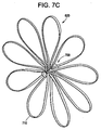
Figure 7C is a perspective view of the anchor under tensioning of the closure line. -
Figure 8A illustrates substantial closure of the PFO track with the closure device deployed through the septum secundum and septum primum along the PFO track to close the PFO. -
Figure 8B illustrates substantial closure of' the PFO track with the closure device deployed through the septum secundum and septum primum. -
Figure 8C illustrates substantial closure of the PFO track with the closure device deployed through the septum secundum and septum primum. -
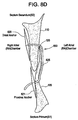
Figure 8D illustrates substantial closure of the PFO track with one leg of the closure device penetrating only through the septum secundum, while the second leg of the closure device penetrates only through the septum primum. -
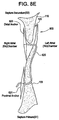
Figure 8E illustrates substantial closure of the PFO track with each leg of the closure device penetrating through the septum primum, but not the septum secundum. -
Figure 8F illustrates substantial closure of the PFO tract with a single penetration through both the septum primum and septum secundum. -
Figure 8G illustrates substantial closure of the PFO track with a single penetration through the septum primum. -
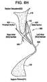
Figure 8H illustrates substantial closure of the PFO, where an ASA is present, with a single penetration only through the septum primum. -
Figure 8I illustrates substantial closure of the PFO with a single penetration through the septum primum. -
Figure 8J illustrates the deployment of the closure device through a single penetration in the septum secundum. -
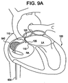
Figure 9A is a section view of the heart illustrating a deployment device having backup support in the form of an axially asymmetric expansion member. -
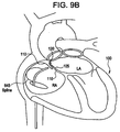
Figure 9B is a section view of the heart illustrating a deployment device having backup support in the form of an axially asymmetric spline. -
Figure 9C is a section view of the heart illustrating a deployment device with a shape along the distal end to provide backup support. -
Figure 10 is a perspective view illustrating exemplary sensors, such as a hydraulic pressure port sensor and electrical pressure transducer. -
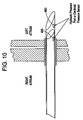
Figure 11 is a perspective partial section view of the deployment device, including the closure device, puncturing through the septum secundum and septum primum according to one embodiment of the present invention. -
Figure 12 illustrates the configuration of thedeployment device 630 andclosure device 600 after theneedle actuator 606 is advanced distally by manipulation of thehandle 610 by the clinician. -
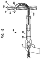
Figure 13 illustrates the final position of thedeployment device 630 andclosure device 600 after theneedle 611 penetrates into the right atrium. -
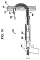
Figure 14 illustrates theanchor 620 deployed from theneedle 611 by theplunger 615. -
Figure 15 illustrates the deployment device pushed back into the left atrium, pulling the needle back from the right atrium to the left atrium -
Figure 16 illustrates the deployment device retracted back through the left atrium into the right atrium. -
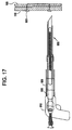
Figure 17 illustrates theclosure device 600 in the fully deployed position. - The various figures show embodiments of the patent foramen ovale (PFO) closure device which can be used in methods of using the device to close a PFO. The device an related methods, which do not form part of the invention, are described herein in connection with mechanically closing a PFO. These devices, however, also are suitable for closing other openings or passageways, including other such openings in the heart, for example atrial septal defects, ventricular septal defects, and patent ducts arterioses, as well as openings or passageways in other portions of a body such as an arteriovenous fistula.
- A human heart has four chambers. The upper chambers are called the left and right atria, and the lower chambers are called the left and right ventricles. A wall of muscle called the septum separates the left and right atria and the left and right ventricles. That portion of the septum that separates the two upper chambers (the right and left atria) of the heart is termed the atrial (or interatrial) septum while the portion of the septum that lies between the two lower chambers (the right and left ventricles) of the heart is called the ventricular (or interventricular) septum.
-
Figure 1 illustrates a short-axis view of theheart 100 at the level of the right atrium (RA) and left atrium (LA), in a plane generally parallel to the atrio-ventricular groove, and at the level of the aortic valve. This view is looking from caudal to cranial.Figure 1 also shows the septum primum (SP) 105, a flap-like structure, which normally covers theforamen ovale 115, an opening in the septum secundum (SS) 110 of theheart 100. In utero, theforamen ovale 115 serves as a physiologic conduit for right-to-left shunting of blood in the fetal heart. After birth, with the establishment of pulmonary circulation, the increased left atrial blood flow and pressure presses the septum primum (SP) 105 against the walls of the septum secundum (SS) 110, covering theforamen ovale 115 and resulting in functional closure of theforamen ovale 115. This closure is usually followed by anatomical closure of theforamen ovale 115 due to fusion of the septum primum (SP) 105 to the septum secundum (SS) 110. - The PFO results when either partial or no fusion of the septum primum 105 to the
septum secundum 110 occurs. When this condition exists, a passageway (PFO track) 120 between the septum primum 105 andseptum secundum 110 may allow communication of blood between the atria. ThisPFO track 120 is typically parallel to the plane of theseptum primum 105, and has an opening that is generally oval in shape.Figure 2 illustrates the opening of thePFO track 120 as viewed from an end of the track. Normally the opening is relatively tall, but quite narrow. The opening may be held closed by the mean pressure in the left atrium, which is typically higher than the right atrium.Figure 3 is a close-up section view of thePFO track 120 held in the closed position by left atrial pressure. In this position, the septum primum 105 acts like a one-way valve, preventing fluid communication between the right and left atria through thePFO track 120. Occasionally, the pressure in the right atrium may temporarily be higher than the left atrium. When this condition occurs, thePFO track 120 opens and allow some fluid to pass from the right atrium to the left atrium, as indicated inFigures 4A and4B . In particular,Figure 4A is a cross-sectional view showing the PFO track ofFigure 2 in an open configuration. Similarly,Figure 4B is a close-up section view illustrating the PFO track in an open configuration. - Although the
PFO track 120 is often held closed, the endothelialized surfaces of the tissues forming thePFO track 120 prevent the tissue from healing together and permanently closing thePFO track 120. As can be seen inFigures 5A - 5C , (a view from line "C-C" ofFigure 1 ), theseptum primum 105 is firmly attached to theseptum secundum 110 around most of the perimeter of theFossa Ovalis 115, but has an opening along one side. The septum primum 105 is often connected, as shown, by two or more extensions of tissue along the sides of thePFO track 120 forming a tunnel.Figure 5D is a magnified section view of thePFO track 120, showing the tunnel formed by the tissue extensions. Typically, the tunnel length in an adult human can range between 2 and 13 mm. - The present invention relates to a system for closing a passageway in a body. The device can be used to close the Patent Foramen Ovale in a human heart. One of ordinary skill in the art would understand that similar embodiments, within the scope of the appended claims, could be used to close other passageways and openings in the body.
-
Figures 6A and6B illustrate a delivery system and device used to close the PFO according to one embodiment of the present invention. Thedevice 600 comprises aflexible closure line 625 coupled to twoexpandable anchors Anchor 620 is coupled to distal end of theclosure line 625, whileanchor 621 is coupled to the proximal end of theflexible closure line 625.Anchor 621 is capable of sliding alongclosure line 625 and locking in desired location to cinch or take-up slack inclosure line 625 length, bringing the proximal anddistal anchors septum secundum 110 and the septum primum 105 in close proximation. - It should be noted that the
septum secundum 110 and the septum primum 105 do not have to be tightly touching to effect proper closure of the PFO. Instead, theseptum secundum 110 and theseptum primum 105 must just be brought close enough to minimize flow from atria to atria (typically flow from left atria to right atria). - The locking mechanism incorporated into
anchor 621 may be a device capable of allowing theclosure line 625 to slide throughanchor 621 in one direction, and prevent sliding movement in the opposite direction. Examples of functionally similar commercial locking mechanisms include the DePuy Mitek RAPIDLOC™ device; zip ties; and similar linear locking devices known in the art. - Alternatively, the
anchor 621 may be fixed to theclosure line 625 at a predetermined distance fromanchor 620. This may particularly be the case when theclosure line 625 has an elastic or recoil ability and is capable of exerting tension when deployed, pulling theanchors septum secundum 110. Aclosure device 600 may include anelastic closure line 625 and aslideable anchor 621. In this device, theanchor 621 is capable of allowing theflexible closure line 625 to slide through theanchor 621 in one direction, and prevent sliding movement in the opposite direction, while theclosure line 625 exerts tension between the twoanchors anchors inelastic closure line 625. - The
closure line 625 may be any biocompatible filament known in the art that is capable of securing the septum primum 105 to theseptum secundum 110. In a preferred examplary form, theclosure line 625 is a surgical suture, such as a multifilament non-biodegradable suture, or a forced entangled fiber filament. Alternatively, theclosure line 625 may be made from an elastic material capable of exerting tension when stretched. In yet another alternative exemplary form, theclosure line 625 may be geometrically configured to exhibit structurally elastic behavior. In another alternative exemplary form, theclosure line 625 may be made from an anelastic material such as elastomeric polymers that are capable of exerting tension when stretched. In yet another alternative exemplary form, theclosure line 625 may be made from a super elastic material such as a nickel titanium alloy. - The
anchors anchors - Structurally deformable materials are materials that can elastically or plastically deform without compromising their integrity. Geometric structures, such as
anchors - Geometric structures made from structurally deformable materials are typically self expanding or mechanically expendable. In a preferred exemplary configuration, the
anchors anchors - Some structurally deformable materials may also be mechanically expandable. Geometric structures can be mechanically expanded by introduction of an external force, through, for example, a mechanical expansion means. Mechanical expansion means are well known in the art and include balloon or cage expansion devices.
- Once an external mechanical force is introduced to the geometric structure, the structure plastically deforms to its desired final configuration.
- The
anchors anchor septum secundum 110, as the case may be, once deployed. - In a preferred exemplary configuration, the
anchors Nitinol hypotube 700 by methods known in the art.Figure 7A is a perspective view of theanchor 620 in the cut pre-expanded form. - The
anchor 620 is then formed into a desired expanded configuration and annealed to assume a stress-free (relaxed) state. In one exemplary configuration, theanchor legs 710. A perspective view of the expandedbasket anchor 620 is illustrated inFigure 7B . - Once the
closure device 600 is deployed, the basket shapedanchors closure line 625, into a flattened "flower petal" shape as illustrated inFigure 7C . In this state, theanchors anchors closure line 625 in tension. -
Figure 8A illustrates the closure device .600 having flower petal shapedanchors proximal anchor 621 inFigure 8A also includes alocking mechanism 622 integrated therein. - This anchor design is not considered a limiting feature of the invention. Other shapes and configurations of
anchors anchors needles anchor needle closure line 625 in place. - Although
Figure 8A illustrates theclosure device 600 deployed through theseptum secundum 110 and septum primum 105 along thePFO track 120, it should be understood that theclosure device 600 may be deployed through other locations to achieve the same results, as illustrated inFigures 8B through 8J . For example,Figure 8B illustrates one leg of theclosure device 600 deployed through both theseptum secundum 110 andseptum primum 105, while the second leg of theclosure device 600 penetrates only through theseptum secundum 110. - Similarly,
Figure 8C illustrates one leg of theclosure device 600 deployed through both theseptum secundum 110 andseptum primum 105, while the second leg of theclosure device 600 penetrates only through theseptum primum 105. -
Figure 8D illustrates one leg of theclosure device 600 penetrating only through theseptum secundum 110, while the second leg of theclosure device 600 penetrates only through theseptum primum 105. -
Figure 8E illustrates each leg of theclosure device 600 penetrating through theseptum primum 105, but not theseptum secundum 110. However, thedistal anchor 620 is located to exert pressure against theseptum secundum 110 and septum primum 105 when theclosure device 600 is tensioned. This pressure forces theseptum secundum 110 and septum primum 105 into close proximity and facilitates the PFO closure. - Each of the above
Figures 8A through 8E illustrate theanchors closure line 625 in a particular orientation. It should be understood that position of theanchor structures -
Figures 8A through 8E illustrate the final position of eachanchor device closure line 625 looping from the right atrial chamber through the left atrial chamber and back into the right atrial chamber. However, it should be understood that theclosure device 600 may be deployed such that the distal anchor '620 is located in the left atrial chamber, while theproximal anchor 621 is located in the right atrial chamber. -
Figures 8F through 8J illustrate theclosure device 600 deployed at various locations across the septum primum 105 and/orseptum secundum 110. Although the penetration through the septum primum 105 and/orseptum secundum 110 are shown at different locations, common to each of the illustrated deployments is the location of thedistal anchor 620 and theproximal anchor 621 in the left and right atrial chambers respectively. -
Figure 8F illustrates substantial closure of the PFO tract 120-with a single penetration through both the septum primum 105 andseptum secundum 110. - It should be noted that both the septum primum 105 and
septum secundum 110 do not have to be penetrated to maintain close enough proximity between the septal tissues to achieve proper closure of the PFO.Figure 8G illustrates substantial closure of the PFO with a single penetration only through theseptum primum 105. In the illustrated exemple, there is significant overlap between the septum primum 105 andseptum secundum 110 creating a fairlylong track 120. The distal andproximal anchors septum secundum 110 to facilitate closing of thePFO track 120 when theclosure line 625 is tensioned. - The
PFO closure device 600 can be used to facilitate closing thePFO track 120 when other defects in the septal wall are present. For example, thePFO closure device 600 may be used when an atrial septal aneurysm (ASA) 805 is present. An ASA is characterized as a saccular deformity, generally at the level of the fossa ovale, which protrudes to the right or left atrium, or both.Figure 8H illustrates substantial closure of the PFO, where an ASA is present, with a single penetration only through theseptum primum 105. However, the distal and proximal anchors, 620 and 621 respectively, are sized to contact both the septum primum 105 andseptum secundum 110 to facilitate closing of thePFO track 120. - The single penetration may also be employed where there is minimal overlap between the septum primum 105 and
septum secundum 110. This so called "short tunnel" PFO may not be readily closed with prior art "intra-tunnel methods.Figure 8I illustrates substantial closure of the PFO with a single penetration through theseptum primum 105. - Similar to the single penetration illustrated in
Figures 8F through 8I , theclosure device 600 may be deployed using a single penetration through theseptum secundum 110 as illustrated inFigure 8J . - The present invention is a removable deployment device which can be used to introduce the
mechanical closure device 600 into the atrium of the heart, preferably through a minimally invasive, transluminal procedure. Onesuch deployment device 630 is shown inFigure 6A . - Minimally invasive heart surgery refers to several approaches for performing heart operations that are less difficult and risky than conventional open-heart surgery. These approaches restore healthy blood flow to the heart without having to stop the heart and put the patient on a heart-lung machine during surgery. Minimally invasive procedures are carried out by entering the body through the skin, a body cavity or anatomical opening, but with the smallest damage possible to these structures. This results in less operative trauma for the patient. It also less expensive, reduces hospitalization time, causes less pain and scarring, and reduces the incidence of complication related to the surgical trauma, speeding the recovery.
- One example of a minimally invasive procedure for performing heart surgery is a trans-thoracic laparoscopic (endoscopic) procedure. The part of the mammalian body that is situated between the neck and the abdomen and supported by the ribs, costal cartilages, and sternum is known as the thorax. This division of the body cavity lies above the diaphragm, is bounded peripherally by the wall of the chest, and contains the heart and lungs. Once into the thorax, the surgeon can gain access to the atrium of the heart through an atriotomy, a surgical incision of an atrium of the heart. For example, if the surgeon wishes to gain access to the right atrium they will perform an atriotomy in the right atrial appendage.
- The primary advantage of a trans-thoracic laparosopic procedure is that there is no need to make a large incision. Instead, the surgeon operates through 3 or 4 tiny openings about the size of buttonholes, while viewing the patient's internal organs on a monitor. There is no large incision to heal, so patients have less pain and recover sooner. Rather than a 152-229 mm (6- to 9- inch) incision, the laparoscopic technique utilized only 4 tiny openings - all less than 12.7 mm (1/2 inch) in diameter.
- Another minimally invasive technique for gaining access to the heart and deploying the closure device is a percutaneous transluminal procedure. Percutaneous surgical techniques pertain to any medical procedure where access to inner organs or other tissue is done via needle-puncture of the skin, rather than by using an "open" approach where inner organs or tissue are exposed (typically with the use of scalpel). The percutaneous approach is commonly used in vascular procedures, where access to heart is gained through the venous or arterial systems. This involves a needle catheter getting access to a blood vessel, followed by the introduction of a wire through the lumen of the needle. It is over this wire that other catheters can be placed into the blood vessel. This technique is known as the modified Seldinger technique. The
PFO closure device 600 may also be deployed via percutaneous methods, which do not from part of the invention, by steerable catheters or guidewires. - In the Seldinger technique a peripheral vein (such as a femoral vein) is punctured with a needle, the puncture wound is dilated with a dilator to a size sufficient to accommodate an introducer sheath, and an introducer sheath with at least one hemostatic valve is seated within the dilated puncture wound while maintaining relative hemostasis.
- Penetration of the interatrial septum requires piecing the septal wall. It is preferred that this penetration is accomplished by using a needle, trocar or similar device to accomplish non-core cutting of the interatrial septum. In one embodiment of the invention, the non-core cutting device is a tubular needle-like structure, however other configurations and shaped structures may be used as would be understood by one skilled in the art. The needle tube is a substantially rigid structure capable of penetrating the
septum secundum 110 and septum primum 105 along thePFO track 120. The needle is preferably sized to be 4.33 mm (13 French) or smaller, most preferably 3.33 mm (10 French) or smaller, and made from a biocompatible material, such as, for example surgical stainless steel, Nitinol, or Cobalt-Chromium alloys. It should be understood that these materials are not meant to limit the scope of the invention. Any biocompatible material capable of being sharpened and holding a sharp edge, and having sufficient strength to facilitate penetration through theseptum secundum 110 and/or septum primum 105, may be suitable. The needle is constructed with a tapered distal end, as is known in the art. In a preferred embodiment, the geometric configuration of the tapered distal end is optimized to minimize induced tissue trauma at the site of penetration. In addition, the needle is of sufficient body length to penetrate both theseptum secundum 110 andseptum primum 105, while still maintaining the needed size and axial flexibility to navigate the tortuous vessel anatomy when being delivered to the heart percutaneously. - With the introducer sheath in place, the guiding catheter or
delivery member 630 of the closure device is introduced through the hemostatic valve of the introducer sheath and is advanced along the peripheral vein, into the region of the vena cavae, and into the right atrium. - In one exemplary use of the delivery system, the distal tip of the
delivery device 630 is positioned against the interatrial septal wall. In the case of a septum having a PFO, the interatrial septal wall may be the septum primum 105 and/orseptum secundum 110, as the case may be. A needle or trocar associated with thedelivery device 630 is then advanced distally until it punctures the septum primum 105 and orseptum secundum 110. A separate dilator may also be advanced with the needle through the septum primum 105 and/orseptum secundum 110 to prepare an access port through the septum primum 105 and/orseptum secundum 110 for seating thedelivery device 630. Thedelivery device 630 traverses across the septum and is seated in the left atrium, thereby providing access forclosure devices 600 through its own inner lumen and into the left atrium. - It is however further contemplated that other left atrial access methods, not forming part of the invention, may be suitable substitutes for using the
delivery device 630 andclosure device 600 of the present invention. In one alternative variation not shown, a "retrograde" approach may be used, wherein thedelivery device 630 is advanced into the left atrium from the arterial system. In this variation, the Seldinger technique is employed to gain vascular access into the arterial system, rather than the venous, for example, at a femoral artery. Thedelivery device 630 is advanced retrogradedly through the aorta, around the aortic arch, into the ventricle, and then into the left atrium through the mitral valve. - Once in the desired atrium of the heart the
closure device 600 is deployed transeptally from one atria to Transeptally is defined as deployment from one atria to the other through the septum (septum primum 105 and/or septum secundum 110), as apposed to intra-atrial access through the PFO tract 120 (tunnel). In the case of a heart having a patent foramen ovale, transeptal penetration may be through the septum primum (SP) 105 and/or septum secundum (SS) 110, or visa versa, whichever the case may be. Preferably, the angle of transeptal penetration is between 45 and 135 degrees to the surface of the septum, but is most preferably orthogonal to the surface of the septum. - By way of example, using right atrial access, the right atrium is first accessed by the delivery device 630 (and closure device 600). The
closure device 600 may then be deployed by penetrating the interatrial septum (septum primum 105 and/or septum secundum 110) from the right atrial chamber to the left atrial chamber in the heart, and deploying thedistal anchor 620 associated with theclosure device 600 into the left atrial chamber. After successful deployment of thedistal anchor 620, thedelivery device 630 may be partially withdrawn from the left atrial chamber to the right atrial chamber, leaving thedistal anchor 620 in place. Theproximal anchor 621 associated with theclosure device 600 can then be deployed into the right atrial chamber. This examplary substantially linear atrial deployment method is shown inFigures 8F through 8J . - In another example of using the delivery system, the right atrium is first accessed by the delivery device 630 (and closure device 600). The
closure device 600 may then be deployed by penetrating the interatrial septum (septum primum 105 and/or septum secundum 110) from the right atrial chamber to the left atrial chamber in the heart. Once in the left atrial chamber, the delivery device 630 (and closure device 600) are turned and re-penetrate the interatrial septum (septum primum 105 and/or septum secundum 110) from the left atrial chamber to the right atrial chamber in the heart though a different access point. The various preferred access points are shown inFigures 8A through 8E . Once back in the right atrial chamber of the heart, thedistal anchor 620 may be deployed. After successful deployment of thedistal anchor 620, thedelivery device 630 may be partially withdrawn from the right atrial chamber to the left atrial chamber, leaving thedistal anchor 620 in place in the right atrium. Thedelivery device 630 may then be withdrawn back through the interatrial septum (septum primum 105 and/or septum secundum 110) from the left atrium to the right atrium. Theproximal anchor 621 associated with theclosure device 600 can then be deployed into the right atrial chamber. - Similar procedures are employed when left an atrial access technique is used. For example, using left atrial access, the left atrium is first accessed by the delivery device 630 (and closure device 600). The
closure device 600 may then be deployed by penetrating the interatrial septum (septum primum 105 and/or septum secundum 110) from the left atrial chamber to the right atrial chamber in the heart, and deploying thedistal anchor 620 associated with the closure device into the first atrium. After successful deployment of thedistal anchor 620, thedelivery device 630 may be partially withdrawn from the right atrial chamber to the left atrial chamber, leaving thedistal anchor 620 in place. Theproximal anchor 621 associated with the closure device can then be deployed into the left atrial chamber. - Once the proximal anchor is deployed, the closure device may be cinched to bring the proximal and distal anchors closer together. This results in the
septum secundum 110 and theseptum primum 105 being brought in close proximation to facilitate closure of the Patent Foramen Ovale. It should be noted that theseptum secundum 110 and the septum primum 105 do not have to be tightly touching to effect proper closure of the PFO. Instead, theseptum secundum 110 and theseptum primum 105 must just be brought close enough to minimize flow from atria to atria (typically flow from right atria to left atria). - To achieve and maintain the proximity between the
septum secundum 110 and theseptum primum 105, it may be necessary to adjust the proximal anchor by uni-axially cinching or sliding theproximal anchor 620 alongclosure line 625. Cinching may comprise uni-axially adjusting the proximal anchor relative to a closure line associated with the closure device. Alternatively, cinching comprises incrementally adjusting the proximal anchor relative to a closure line associated with the closure device. - Once the closure device is cinched in place the method may further comprise assessing the degree of proximation between the
septum secundum 110 and theseptum primum 105. - The clinician may visually assess the proximation though an endoscopic or fluoroscopic procedure. In addition, other methods may be used to measure the proximation between the
septum secundum 110 and theseptum primum 105, such as through pressure observation or infrared imaging. - After proper cinching, any unwanted length of
closure line 625 that remains unconstrained within the right atrium may be mechanically removed. Devices known in the art capable of removing theexcess closure line 625 include catheter-based snare and cut devices. In addition to independent devices, a mechanical cut and removal mechanism may be integrated into the deployment device. - The closure device will then be in position, with the
anchors septum secundum 110, and theclosure line 625 connecting theanchors septum secundum 110, thus holding the septum primum 105 in place. - To locate and deploy the
closure device 600 at the location of the PFO, the present invention utilizes aremovable deployment device 630. Thedeployment device 630 loaded with aclosure device 600 according to one embodiment of the present invention is illustrated inFigure 6A . Theremovable deployment device 630 comprises a deflectableneedle tip assembly 605, aneedle actuator 606, acatheter shaft 607, aplunger 608, acatheter sheath 609 and ahandle 610. - The
catheter sheath 609 is the outermost tube-like structure that is sized to house theneedle assembly 605,catheter shaft 607,needle actuator 606 and plunger during delivery. Thecatheter sheath 609 is diametrically sized to slideably engage thecatheter shaft 607. The main function of thecatheter sheath 609 is to protect theneedle assembly 605, as well as the body lumen, during delivery. Thecatheter sheath 609 is attached along its proximal end to handle 610. Catheter sheaths are well known in the art. - The
handle 610 is operated by a clinician to deflect theneedle assembly 605 in the desired direction. As such, the handle has a means for receiving movement from the clinician, and transferring that movement into translational movement for actuation ofneedle 611 deflection. - The
needle tip assembly 605 further comprises aneedle 611 andneedle support tube 612, capable of puncturing through theseptum secundum 110 and/orseptum primum 105. Theneedle 611 is a substantially rigid needle like structure capable of penetrating theseptum secundum 110 and septum primum 105 along thePFO track 120. Theneedle 611 is preferably sized to be 10 French or smaller and made from a biocompatible material, such as, for example surgical stainless steel, Nitinol, or Cobalt-Chromium alloys. It should be understood that these materials are not meant to limit the scope of the invention. Any biocompatible material capable of being sharpened and holding a sharp edge, and having sufficient strength to facilitate penetration through theseptum secundum 110 and/or septum primum, may be suitable. Theneedle 611 is constructed with a tapered distal end, as is known in the art. - The geometric configuration of the tapered distal end is optimized to minimize induced tissue trauma at the site of penetration. In addition, the
needle 611 is of sufficient body length to penetrate both theseptum secundum 110 andseptum primum 105, while still maintaining the needed size and axial flexibility to navigate the tortuous vessel anatomy when being delivered to theheart 100. - To assist the
needle tip assembly 605 in deflecting within theneedle support tube 612, the needle is comprised of aneedle tip 613 connected along its proximal end to a first elongate member having aneedle tang 614 and a second elongate needle member, i.e.needle spine 615. Theneedle spine 615 is further connected to theproximal needle body 616. The proximal end of the firstelongate needle member 614 ends with a tab (tab B), which acts as a pivot point for the deflection of theneedle tip assembly 605 as explained below. Theneedle support tube 612 acts to constrain theneedle 611 when deflecting. As disclosed above, the purpose of this connection point is to provide a pivot point for theneedle 611 when deflecting. However, one of skill in the art would understand that thecatheter shaft 607 could be made an integral part of theneedle assembly 605. - The
catheter shaft 607 is an elongate tube-like structure substantially coaxial withcatheter sheath 609, and diametrically sized such that theneedle actuator 606 is slideably engaged withcatheter shaft 607. That is to say, the outer diameter ofneedle actuator 606 is smaller than the inner bore diameter ofcatheter shaft 607, allowing theneedle actuator 606 to slide within thecatheter shaft 607. - The proximal end of the
needle body 616 is attached to aneedle actuator 606 at tab A. The proximal end of the needle actuator is attached to thehandle 610 and provide the mechanism for transferring the translational movement supplied by thehandle 610 to theneedle assembly 605. This translational movement results in the needle assembly deflecting theneedle 611 up or down, depending on the movement imparted by thehandle 610. Accordingly, theneedle actuator 606 must be rigid enough to transmit the translational movement, yet flexible enough to endure the tortuous anatomy when the deployment device is delivered through the body's vasculature. One of skill in the art would understand that theneedle actuator 606 could be made an integral part of theneedle assembly 605. - To deploy the
closure device 600, thedeployment device 630 utilizes aplunger 608. Theplunger 608 is substantially coaxial withcatheter shaft 607 and diametrically sized such that theplunger 608 is slideably engaged withcatheter shaft 607. That is to say, the outer diameter ofplunger 608 is smaller than the inner bore diameter ofcatheter shaft 607, allowing theplunger 615 to be pushed through and telescope from thecatheter shaft 607 andneedle 611. In the illustrated embodiment,plunger 608 is also appropriately sized to pushanchor 620 from the distal end of theneedle 611. - During deployment,
plunger 608 pushes againstanchor 620 untilanchor 620 is deployed from the distal end ofneedle 611. The movement ofanchor 620 necessarily translates to movement ofanchor 621 throughclosure line 625.Anchor 621 is appropriately sized to allowanchor 621 to slide throughneedle 611. Accordingly, the inside diameter ofplunger 608 is smaller than the outside diameter ofanchor 620.. Conversely, the outside diameter ofanchor 621 must be smaller than the inside diameter ofneedle 611. - In one embodiment of the invention, the
plunger 608. is made from a flexible material such that it can be deformed byneedle 611 uponinner needle 611's deflection byneedle actuator 606. Flexibility may also be imparted to theplunger 608 by geometry, such as fabricating theplunger 608 from spring steel into a tightly wound coil. However, theplunger 608 must also have the necessary stiffness to be able to deploy theclosure device 600 from the distal end ofneedle 611. In a preferred embodiment, theplunger 608 is made from stainless steel, Nitinol, or Cobalt-Chromium alloy, but any material exhibiting the desire characteristics of flexibility and "push-ability" may be used. - This curved shape of the needle assembly may be assumed by mechanical manipulation, such as through manipulation of the
needle actuator 606. Referring again toFigures 6C and 6D , theneedle 611 is shown and described as having separate components (needle body 616,needle spine 615,needle tang 614 and needle trip 613). However, it should be understood that the needle is broken down into separate components for ease of illustration and explanation. In a preferred embodiment of the invention, thebody 616,spine 615,tang 614 andneedle tip 613 are formed as as monolithic unit from a single piece of material. - As previously described, the
needle actuator 606 is slideably engaged withcatheter shaft 607, and thus can freely move withincatheter shaft 607. Thetang 614 is attached to thecatheter shaft 607 at tab B, such that thecatheter shaft 607 andtang 614 cannot move relative to one another. Similarly, the proximal end ofneedle body 616 is attached to the distal end ofneedle actuator 606 at tab A, such that theneedle body 616 andneedle actuator 606 cannot move relative to one another. However, theneedle spine 615 is not attached to thecatheter shaft 607, and is free to move within the catheter shaft. Thespine 615 ofneedle 611 is rigidly attached to the distal end ofneedle body 616 such that any movement ofbody 616 is translated directly to thespine 615. To deflect theneedle 611, theneedle actuator 606 is translated relative to thecatheter shaft 607. This movement is translated to thespine 615, which is free to move relative to thecatheter shaft 607. Since thetang 614 ofneedle 611 is constrained by thecatheter shaft 607, thetang 614, particularly the tab B, will act as a pivot point forneedle 611 to deflect. Referring toFigure 6A , if theneedle actuator 606 is translated distally, thespine 615 is translated distally relative to thecatheter shaft 607 and deflect theneedle 611 upward. Similarly, if theneedle actuator 606 is translated proximally, thespine 615 is translated proximally relative to thecatheter shaft 607, and deflect theneedle 611 downward. - In a preferred embodiment, the
needle 611 is fabricated to resume a pre-determined configuration when the force providing the translation of theneedle actuator 606 is removed. One material exhibiting shape memory or super-elastic characteristics is Nitinol. - Nitinol is utilized in a wide variety of applications, including medical device applications as described above. Nitinol or NiTi alloys are widely utilized in the fabrication or construction of medical devices for a number of reasons, including its biomechanical compatibility, its biocompatibility, its fatigue resistance, its kink resistance, its uniform plastic deformation, its magnetic resonance imaging compatibility, its ability to exert constant and gentle outward pressure, its dynamic interference, its thermal deployment capability, its elastic deployment capability, its hysteresis characteristics, and is moderately radiopaque.
- Nitinol, as described above, exhibits shape memory and/or super-elastic characteristics. Shape memory characteristics may be simplistically described as follows. A metallic structure, for example, a Nitinol tube that is in an Austenitic phase may be cooled to a temperature such that it is in the Martensitic phase. Once in the Martensitic phase, the Nitinol tube may be deformed into a particular configuration or shape by the application of stress. As long as the Nitinol tube is maintained in the Martensitic phase, the Nitinol tube will remain in its deformed shape. If the Nitinol tube is heated to a temperature sufficient to cause the Nitinol tube to reach the Austenitic phase, the Nitinol tube will return to its original or programmed shape. The original shape is programmed to be a particular shape by well-known techniques.
- Super-elastic characteristics may be simplistically described as follows. A metallic structure for example, a Nitinol tube that is in an Austenitic phase may be deformed to a particular shape or configuration by the application of mechanical energy. The application of mechanical energy causes a stress induced Martensitic phase transformation. In other words, the mechanical energy causes the Nitinol tube to transform from the Austenitic phase to the Martensitic phase. By utilizing the appropriate measuring instruments, one can determined that the stress from the mechanical energy causes a temperature drop in the Nitinol tube. Once the mechanical energy or stress is released, the Nitinol tube undergoes another mechanical phase transformation back to the Austenitic phase and thus its original or programmed shape. As described above the original shape is programmed by well know techniques. The Martensitic and Austenitic phases are common phases in many metals.
- Medical devices constructed from Nitinol are typically utilized in both the Martensitic phase and/or the Austenitic phase. The Martensitic phase is the low temperature phase. A material is in the Martensitic phase is typically very soft and malleable. These properties make it easier to shape or configure the Nitinol into complicated or complex structures. The Austenitic phase is the high temperature phase. A material in the Austenitic phase is generally much stronger than the material in the Martensitic phase. Typically, many medical devices are cooled to the Martensitic phase for manipulation and loading into delivery systems. When the device is deployed at body temperature, they return to the Austenitic phase.
- Other materials that have shape memory characteristics may also be used, for example, some polymers and metallic composition materials. It should be understood that these materials are not meant to limit the scope of the invention. Any biocompatible material capable of being sharpened and holding a sharp edge, and having sufficient strength to facilitate penetration through the
septum secundum 110 and/or septum primum, may be suitable. Theinner needle 610 is constructed with a tapered distal end, as is know in the art. The geometric configuration of the tapered distal end is optimized to minimize induced tissue trauma at the site of penetration. - Regardless of the material used, the
inner needle 610 must be flexible enough to remain substantially straight when constrained insideouter needle 605, but rigid enough to puncture through theseptum secundum 110 and septum primum 105 once deployed from the distal end ofouter needle 605. - A location monitoring system to facilitate placement of the
deployment device 630 is also disclosed. In particular, the location monitoring device may assist in determining whether the clinician is in the correct chamber of the heart. - The location monitoring system may further include the ability to measure localized pressure relative to the distal end of the
deployment device 630. The pressure measurement read by the location monitoring system may be achieved by electronic, mechanical and/or physical means, such as a solid-state pressure transducer, spring loaded diaphragm, hydraulic pressure port, and/or communicating manometer. These and other pressure measurement techniques would be known by one of skill in the art.Figure 10 is a perspective view illustrating exemplary sensors, such as ahydraulic pressure port 655 orelectrical pressure transducer 660. - By way of example it is well known that pressures vary in different locations within the cardiovascular system. Specifically, gage pressure in the right and left atrium are know to range from approximately 133-800 Pa (1-6 mmHg) to 1333 Pa (10 mmHg) respectfully. Similarly, gage pressure within the ascending aorta ranges from approximately 16 kPa to 21.3 kPa (120 to 160 mmHg) during systole.
- Before deployment, the clinician will first monitor pressure within the right atrium. This reading should indicate a pressure of 133-800 Pa (1-6 mmHg). The distal end of the
needle 611 will be inserted through the septal wall (septum primum 105 and/or septum secundum 110) and into the left atrium. The monitored pressure should change to approximately 1333 Pa (10 mmHg). A much higher reading, such as in the range of approximately 16 to 21.3 kPa (120 to 160 mmHg), indicates puncture of the aorta. The clinician will then have to retract theneedle 611 and reposition thedelivery device 630 for re-entry. Similarly, once in the left atrium theneedle 611 is advanced back into the right atrium. The clinician should observe a pressure change from 133 Pa (10 mmHg) to 133-800 Pa (1-6 mmHg). - To facilitate deployment of the
closure device 600, thedeployment device 630 may include features that provide backup support. This backup support may include, for example: an axially asymmetric expansion member attached along ancatheter sheath 609, such as a balloon orself expanding cage 640; aspline 645; or imparting ashape 650 along the body of thedeployment device 630. Examples of these backup support features are illustrated inFigures 9A through 9C , respectively. - It should be understood that the
outer shaft 635 may be part of the guiding catheter, or integrated into thedeployment device 630. These and other such backup support devices would be understood by one of skill in the art. These backup support features could also be incorporated onto accessory devices, such as the guide catheter. - In one example of using the delivery system of the invention, the
deployment device 630 is first positioned within the left atrium according to a transeptal access method, which is further described in more detail as follows. The right venous system is first accessed using the "Seldinger" technique, wherein a peripheral vein (such as a femoral vein) is punctured with a needle, the puncture wound is dilated with a dilator to a size sufficient to accommodate an introducer sheath, and an introducer sheath with at least one hemostatic valve is seated within the dilated puncture wound while maintaining relative hemostasis. With the introducer sheath in place, the guiding catheter or sheath is introduced through the hemostatic valve of the introducer sheath and is advanced along the peripheral vein, into the region of the vena cavae, and into the right atrium. - Once in the right atrium, the distal tip of the
catheter sheath 609 is positioned against theseptum secundum 110 in the intra-atrial septal wall. Thecatheter sheath 609 is then retracted exposing theneedle assembly 605. Thedeployment device 630 is then advanced distally until theneedle assembly 605 punctures through both theseptum secundum 110 and septum primum 105 into the left atrium. The configuration of thedeployment device 630, includingclosure device 600 puncturing through theseptum secundum 110 andseptum primum 105 is shown inFigure 11 . - Once the
deployment device 630, particularly theneedle assembly 605 penetrates through both theseptum secundum 110 andseptum primum 105, theneedle actuator 606 is advanced distally, causing theneedle 611 to deflect upward.Figure 12 illustrates the configuration of thedeployment device 630 andclosure device 600 after theneedle actuator 606 is advanced distally by manipulation of thehandle 610 by the clinician. - After the
needle 611 is deflected, thedeployment device 630 is pulled back until theneedle 611 penetrates through the septum primum 105 andseptum secundum 110, respectively, into the right atrium. This is accomplished by ensuring that theneedle 611 remains fixed relative tocatheter shaft 607 andcatheter sheath 609, and then withdrawing thecatheter shaft 607 andcatheter sheath 609 left atrium until theneedle 611 makes the necessary penetration into the right atrium.Figure 13 illustrates the final position of thedeployment device 630 andclosure device 600 after theneedle 611 penetrates into the right atrium. - After the
needle 611 has penetrated the septum primum 105 andseptum secundum 110 into the right atrium, thefirst anchor 620 can be deployed. As earlier described, theanchor 620 is deployed into the right atrium by holding thecatheter shaft 607 steady, and advancing theplunger 615 through theneedle 611. During deployment,plunger 615 pushes against the back portion ofhook 620 untilanchor 620 is advanced from the distal end ofneedle 611. The movement ofanchor 620 necessarily translates to movement ofanchor 621 throughclosure line 625. Asanchor 620 enters the right atrium the shape memory material properties allow theanchor 620 to assume it unconstrained shape.Figure 14 illustrates theanchor 620 deployed from theneedle 611 by theplunger 615. - To deploy
anchor 621, thedeployment device 630 is pushed back into the left atrium, pulling the needle back from the right atrium to the left atrium to a position indicated inFigure 15 . This will leave theplunger 615 and the closure assembly' in place penetrating the septum primum 105 andseptum secundum 110 in two places. Theanchor 621 will remain in the constrained position insideplunger 615. Theneedle 611 is then allowed to revert to its original straight configuration, and thedeployment device 630 is retracted back through the left atrium into the right' atrium as shown inFigure 16 . This will leave theclosure device 600 in place, withanchor 620 fully deployed against theseptum secundum 110, andanchor 621 constrained insideneedle 611. Theplunger 615 can once again be advance and theneedle 611 withdrawn from the septum primum 105 andseptum secundum 110 respectively, releasing theanchor 621 to the fully unrestrained shape. If necessary,anchor 621 may be slid towardanchor 620 alongclosure line 625 until sufficient compression is achieved between septum primum 105 andseptum secundum 110. Any unwanted length ofclosure line 625 that remains unconstrained within the right atrium may be mechanically removed. Devices known in the art capable of removing theexcess closure line 625 includes catheter-based snare and cut devices. In addition to independent devices, a mechanical cut and removal mechanism may be integrated intro thedeployment device 630. - The closure device will then be in position, with the
anchors septum secundum 110, and theclosure line 625 connecting theanchors septum secundum 110, thus holding the septum primum 105 in place. -
Figure 17 illustrates theclosure device 600 in the fully deployed position. - These and other objects and advantages of this invention will become obvious to a person of ordinary skill in this art upon reading of the detailed description of this invention including the associated drawings.
- Various other modifications, adaptations, and alternative designs are of course possible in light of the above teachings. Therefore, it should be understood at this time that within the scope of the appended claims the invention might be practiced otherwise than as specifically described herein.
Claims (11)
- A delivery system (630) for deploying a medical device (600) used to close a passageway in a body comprising:an elongate member (607) having a proximal and distal end;a deflectable needle tip assembly (605) slideably engaged within the elongate member (607), the deflectable needle tip assembly (605) having luminal and abluminal surfaces;an actuator (606) slideably engaged within the elongate member (607) and attached to the needle tip assembly (605) such that translational movement of the actuator (606) causes deflection of the deflectable needle assembly (605);wherein the needle tip assembly (605) comprises a needle (611) having luminal and abluminal surfaces, and a support tube (612) covering at least a portion of the needle (611) wherein the needle (611) has proximal and distal ends; characterised in that the needle (611) further comprises:a tubular needle body (616) along the proximal end of the needle, the needle body being attached to the actuator (606);a tubular needle tip (613) along the distal end of the needle (611), the needle tip (613) terminating with a chamfered end;a first elongate member (614) attached between the proximal end of needle tip (613) and the distal end of the elongate member (607) ; anda second elongate member (615) attached between the proximal end of distal tip (613) and distal end of needle body.
- The delivery system (630) of claim 1 further comprising a delivery mechanism for deploying the medical device (600), the delivery mechanism being slideably engaged within the deflectable needle assembly (605) .
- The delivery system (630) of claim 2 wherein the delivery mechanism is a plunger (608).
- The delivery system (630) of claim 1 further comprising a mechanism for imparting linear translational movement to the actuator (606).
- The delivery system (630) of claim 4 wherein the mechanism for imparting movement to the actuator (606) is a handle (610) attached to the proximal end of the actuator (606).
- The delivery system (630) of claim 1 further comprising a sheath (609) coaxially disposed over the elongate member (607) diametrically sized such that the elongate member (607) is slideably engaged within the sheath (609).
- The delivery system (630) of claim 1 wherein the needle (611) is 3.33 mm (10 French) or smaller in diameter.
- The delivery system (630) of claim 1 wherein the needle (611) comprises nitinol.
- The delivery system (630) of claim 1 wherein the needle (611) is between 3 and 7 millimeters long.
- The delivery system (630) of claim 1 wherein the needle support tube (612) constrains at least a portion of the first and the second elongate members during deflection of the needle assembly.
- The delivery system (630) of claim 1 further comprising a sheath coaxial with the elongate member and diametrically sized so the elongate member is slideably engaged within the sheath.
Applications Claiming Priority (2)
| Application Number | Priority Date | Filing Date | Title |
|---|---|---|---|
| US69731605P | 2005-07-07 | 2005-07-07 | |
| PCT/US2006/026294 WO2007008565A1 (en) | 2005-07-07 | 2006-07-07 | Patent foramen ovale closure device with steerable delivery system |
Publications (2)
| Publication Number | Publication Date |
|---|---|
| EP1898801A1 EP1898801A1 (en) | 2008-03-19 |
| EP1898801B1 true EP1898801B1 (en) | 2011-12-21 |
Family
ID=37144290
Family Applications (1)
| Application Number | Title | Priority Date | Filing Date |
|---|---|---|---|
| EP06786451A Not-in-force EP1898801B1 (en) | 2005-07-07 | 2006-07-07 | Patent foramen ovale closure device with steerable delivery system |
Country Status (9)
| Country | Link |
|---|---|
| US (1) | US8834562B2 (en) |
| EP (1) | EP1898801B1 (en) |
| JP (1) | JP2009500118A (en) |
| CN (1) | CN101257852B (en) |
| AT (1) | ATE537757T1 (en) |
| AU (1) | AU2006269384B2 (en) |
| CA (1) | CA2614424C (en) |
| ES (1) | ES2375738T3 (en) |
| WO (1) | WO2007008565A1 (en) |
Cited By (2)
| Publication number | Priority date | Publication date | Assignee | Title |
|---|---|---|---|---|
| WO2013158354A1 (en) | 2012-04-17 | 2013-10-24 | Indian Wells Medical, Inc. | Steerable endoluminal punch |
| US11844548B1 (en) | 2014-09-13 | 2023-12-19 | Indian Wells Medical, Inc. | Steerable endoluminal punch |
Families Citing this family (53)
| Publication number | Priority date | Publication date | Assignee | Title |
|---|---|---|---|---|
| EP1196093B1 (en) | 1999-07-02 | 2006-06-14 | Quickpass, Inc. | Suturing device |
| US8614768B2 (en) * | 2002-03-18 | 2013-12-24 | Raytheon Company | Miniaturized imaging device including GRIN lens optically coupled to SSID |
| EP1909655A2 (en) | 2005-06-20 | 2008-04-16 | Sutura, Inc. | Method and apparatus for applying a knot to a suture |
| CA2621197A1 (en) * | 2005-09-01 | 2007-03-08 | Cordis Corporation | Patent foramen ovale closure method |
| US8758375B2 (en) | 2005-09-28 | 2014-06-24 | Olympus Medical Systems Corp | Method for suturing perforation |
| US7771388B2 (en) | 2005-10-12 | 2010-08-10 | Daniel Olsen | Steerable catheter system |
| CA2671713C (en) * | 2006-12-07 | 2014-09-09 | Cordis Corporation | Steerable catheter system |
| US10166066B2 (en) | 2007-03-13 | 2019-01-01 | University Of Virginia Patent Foundation | Epicardial ablation catheter and method of use |
| US11058354B2 (en) | 2007-03-19 | 2021-07-13 | University Of Virginia Patent Foundation | Access needle with direct visualization and related methods |
| US9468396B2 (en) | 2007-03-19 | 2016-10-18 | University Of Virginia Patent Foundation | Systems and methods for determining location of an access needle in a subject |
| EP2134253B1 (en) | 2007-03-19 | 2022-01-26 | University Of Virginia Patent Foundation | Access needle pressure sensor device |
| US9211405B2 (en) | 2007-03-22 | 2015-12-15 | University Of Virginia Patent Foundation | Electrode catheter for ablation purposes and related method thereof |
| WO2008121738A2 (en) | 2007-03-29 | 2008-10-09 | Sutura, Inc. | Suturing devices and methods for closing a patent foramen ovale |
| US7835074B2 (en) | 2007-06-05 | 2010-11-16 | Sterling Lc | Mini-scope for multi-directional imaging |
| US20100241185A1 (en) | 2007-11-09 | 2010-09-23 | University Of Virginia Patent Foundation | Steerable epicardial pacing catheter system placed via the subxiphoid process |
| WO2009082596A1 (en) * | 2007-12-18 | 2009-07-02 | Wilson-Cook Medical, Inc. | Device and method for placement of tissue anchors |
| US8771296B2 (en) | 2008-05-09 | 2014-07-08 | Nobles Medical Technologies Inc. | Suturing devices and methods for suturing an anatomic valve |
| US20090287048A1 (en) * | 2008-05-16 | 2009-11-19 | Sterling Lc | Method and apparatus for imaging within a living body |
| JP5596027B2 (en) | 2008-06-18 | 2014-09-24 | レイセオン カンパニー | catheter |
| WO2009155432A2 (en) * | 2008-06-18 | 2009-12-23 | Sterling Lc | Miniaturized imaging device multiple grin lenses optically coupled to multiple ssids |
| US8486735B2 (en) * | 2008-07-30 | 2013-07-16 | Raytheon Company | Method and device for incremental wavelength variation to analyze tissue |
| US8317679B2 (en) * | 2008-10-06 | 2012-11-27 | Cook Medical Technologies Llc | Endcap for safely deploying tissue anchors |
| WO2010053916A2 (en) | 2008-11-04 | 2010-05-14 | Sterling Lc | Method and device for wavelength shifted imaging |
| US9642534B2 (en) | 2009-09-11 | 2017-05-09 | University Of Virginia Patent Foundation | Systems and methods for determining location of an access needle in a subject |
| WO2011041730A2 (en) | 2009-10-01 | 2011-04-07 | Jacobsen Stephen C | Light diffusion apparatus |
| US9661996B2 (en) | 2009-10-01 | 2017-05-30 | Sarcos Lc | Needle delivered imaging device |
| US9144664B2 (en) | 2009-10-01 | 2015-09-29 | Sarcos Lc | Method and apparatus for manipulating movement of a micro-catheter |
| US8828028B2 (en) | 2009-11-03 | 2014-09-09 | Raytheon Company | Suture device and method for closing a planar opening |
| US9307980B2 (en) | 2010-01-22 | 2016-04-12 | 4Tech Inc. | Tricuspid valve repair using tension |
| US10058323B2 (en) | 2010-01-22 | 2018-08-28 | 4 Tech Inc. | Tricuspid valve repair using tension |
| WO2011094619A1 (en) * | 2010-01-29 | 2011-08-04 | Med-Venture Investments, Llc | Methods and apparatuses for suturing of cardiac openings |
| CA2790328C (en) | 2010-02-18 | 2017-04-18 | University Of Virginia Patent Foundation | System, method, and computer program product for simulating epicardial electrophysiology procedures |
| US9526483B2 (en) * | 2010-07-15 | 2016-12-27 | Medtronic Vascular Galway | Apical closure system |
| EP3644194B1 (en) | 2011-04-15 | 2022-12-07 | Heartstitch, Inc. | Suturing devices for suturing an anatomic valve |
| WO2013170081A1 (en) | 2012-05-11 | 2013-11-14 | Heartstitch, Inc. | Suturing devices and methods for suturing an anatomic structure |
| JP6412505B2 (en) | 2012-12-06 | 2018-10-24 | インディアン ウェルズ メディカル インコーポレイテッドIndian Wells Medical,Inc. | Steerable guidewire and method of use |
| EP2943132B1 (en) | 2013-01-09 | 2018-03-28 | 4Tech Inc. | Soft tissue anchors |
| EP3016598B1 (en) | 2013-07-02 | 2018-10-10 | Med-venture Investments, LLC | Suturing devices for suturing an anatomic structure |
| US10022114B2 (en) | 2013-10-30 | 2018-07-17 | 4Tech Inc. | Percutaneous tether locking |
| CN103654883B (en) * | 2013-12-06 | 2017-01-04 | 深圳市先健生物材料技术有限公司 | The stopper of with locking mechanism |
| JP6469109B2 (en) | 2013-12-06 | 2019-02-13 | メッド − ベンチャー インベストメンツ、エルエルシー | Suture method and apparatus |
| WO2015193728A2 (en) * | 2014-06-19 | 2015-12-23 | 4Tech Inc. | Cardiac tissue cinching |
| US10178993B2 (en) | 2014-07-11 | 2019-01-15 | Cardio Medical Solutions, Inc. | Device and method for assisting end-to-side anastomosis |
| EP3169248B1 (en) * | 2014-07-20 | 2021-03-31 | Riina, Howard, Anthony | Device for surgical suturing |
| US10786655B2 (en) | 2016-03-14 | 2020-09-29 | Indian Wells Medical, Inc. | Steerable guidewire and method of use |
| US10687801B2 (en) | 2016-04-11 | 2020-06-23 | Nobles Medical Technologies Ii, Inc. | Suture spools for tissue suturing device |
| US11839370B2 (en) | 2017-06-19 | 2023-12-12 | Heartstitch, Inc. | Suturing devices and methods for suturing an opening in the apex of the heart |
| EP3641663B1 (en) | 2017-06-19 | 2022-03-02 | Heartstitch, Inc. | Suturing systems and methods for suturing body tissue |
| EP3668415B1 (en) | 2017-08-18 | 2023-10-25 | Nobles Medical Technologies II, Inc. | Apparatus for applying a knot to a suture |
| CN107822743A (en) * | 2017-10-20 | 2018-03-23 | 北京迈迪顶峰医疗科技有限公司 | A kind of system that leaflet reparation is carried out for Minimally Invasive Surgery |
| US11134984B2 (en) * | 2018-07-31 | 2021-10-05 | Medtronic, Inc. | Pressure-sensing implant tools |
| CN113827284B (en) * | 2021-09-15 | 2023-04-14 | 宁波迪创医疗科技有限公司 | Tissue defect's closure apparatus |
| CN117224179B (en) * | 2023-09-05 | 2024-02-23 | 南京思脉德医疗科技有限公司 | Stitch adjusting mechanism for suturing and suturing device for patent foramen ovale |
Family Cites Families (25)
| Publication number | Priority date | Publication date | Assignee | Title |
|---|---|---|---|---|
| US3990619A (en) * | 1975-11-12 | 1976-11-09 | Dennison Manufacturing Company | Fastener attachment needle |
| US4235238A (en) * | 1978-05-11 | 1980-11-25 | Olympus Optical Co., Ltd. | Apparatus for suturing coeliac tissues |
| WO1991015155A1 (en) | 1990-04-02 | 1991-10-17 | Kanji Inoue | Device for closing shunt opening by nonoperative method |
| US5284488A (en) | 1992-12-23 | 1994-02-08 | Sideris Eleftherios B | Adjustable devices for the occlusion of cardiac defects |
| US6231561B1 (en) | 1999-09-20 | 2001-05-15 | Appriva Medical, Inc. | Method and apparatus for closing a body lumen |
| US6508828B1 (en) | 2000-11-03 | 2003-01-21 | Radi Medical Systems Ab | Sealing device and wound closure device |
| US7842050B2 (en) | 2001-02-26 | 2010-11-30 | Diduch David R | Suture passing devices |
| US7374560B2 (en) | 2001-05-01 | 2008-05-20 | St. Jude Medical, Cardiology Division, Inc. | Emboli protection devices and related methods of use |
| US7422579B2 (en) | 2001-05-01 | 2008-09-09 | St. Jude Medical Cardiology Divison, Inc. | Emboli protection devices and related methods of use |
| US7604612B2 (en) | 2001-05-01 | 2009-10-20 | St. Jude Medical, Cardiology Division, Inc. | Emboli protection devices and related methods of use |
| US7338514B2 (en) | 2001-06-01 | 2008-03-04 | St. Jude Medical, Cardiology Division, Inc. | Closure devices, related delivery methods and tools, and related methods of use |
| USPP13440P2 (en) * | 2001-07-09 | 2002-12-31 | Yoder Brothers, Inc. | Chrysanthemum plant named ‘Icon’ |
| US6796963B2 (en) * | 2001-07-10 | 2004-09-28 | Myocardial Therapeutics, Inc. | Flexible tissue injection catheters with controlled depth penetration |
| JP2005525843A (en) * | 2002-01-14 | 2005-09-02 | エヌエムティー メディカル インコーポレイテッド | Patent foramen ovale (PFO) occlusion method and apparatus |
| US7976564B2 (en) | 2002-05-06 | 2011-07-12 | St. Jude Medical, Cardiology Division, Inc. | PFO closure devices and related methods of use |
| AU2003294682A1 (en) | 2002-12-09 | 2004-06-30 | Nmt Medical, Inc. | Septal closure devices |
| US20040267306A1 (en) | 2003-04-11 | 2004-12-30 | Velocimed, L.L.C. | Closure devices, related delivery methods, and related methods of use |
| US8372112B2 (en) | 2003-04-11 | 2013-02-12 | St. Jude Medical, Cardiology Division, Inc. | Closure devices, related delivery methods, and related methods of use |
| JP4166632B2 (en) * | 2003-06-06 | 2008-10-15 | オリンパス株式会社 | Suture device |
| USPP15925P3 (en) | 2003-07-09 | 2005-08-23 | North Carolina State University | Hybrid Calycanthus plant named ‘Venus’ |
| CA2538476A1 (en) | 2003-09-11 | 2005-04-21 | Nmt Medical, Inc. | Devices, systems, and methods for suturing tissue |
| EP1680027A2 (en) | 2003-10-10 | 2006-07-19 | Proximare, Inc. | Patent foramen ovale (pfo) closure devices, delivery apparatus and related methods and systems |
| ES2293357T3 (en) * | 2003-10-24 | 2008-03-16 | Ev3 Endovascular, Inc. | CLOSURE SYSTEM OF A PERMEABLE OVAL FORM. |
| WO2005046487A1 (en) * | 2003-11-06 | 2005-05-26 | Nmt Medical, Inc. | Transseptal puncture apparatus |
| JP2006053664A (en) | 2004-08-10 | 2006-02-23 | Fujitsu Ltd | Method for registering identification mark, electronic device, and computer program |
-
2006
- 2006-07-07 ES ES06786451T patent/ES2375738T3/en active Active
- 2006-07-07 CA CA2614424A patent/CA2614424C/en not_active Expired - Fee Related
- 2006-07-07 WO PCT/US2006/026294 patent/WO2007008565A1/en active Application Filing
- 2006-07-07 EP EP06786451A patent/EP1898801B1/en not_active Not-in-force
- 2006-07-07 AT AT06786451T patent/ATE537757T1/en active
- 2006-07-07 CN CN200680032524.2A patent/CN101257852B/en active Active
- 2006-07-07 US US11/483,240 patent/US8834562B2/en active Active
- 2006-07-07 JP JP2008520380A patent/JP2009500118A/en not_active Withdrawn
- 2006-07-07 AU AU2006269384A patent/AU2006269384B2/en not_active Ceased
Cited By (2)
| Publication number | Priority date | Publication date | Assignee | Title |
|---|---|---|---|---|
| WO2013158354A1 (en) | 2012-04-17 | 2013-10-24 | Indian Wells Medical, Inc. | Steerable endoluminal punch |
| US11844548B1 (en) | 2014-09-13 | 2023-12-19 | Indian Wells Medical, Inc. | Steerable endoluminal punch |
Also Published As
| Publication number | Publication date |
|---|---|
| AU2006269384B2 (en) | 2012-03-29 |
| JP2009500118A (en) | 2009-01-08 |
| US8834562B2 (en) | 2014-09-16 |
| EP1898801A1 (en) | 2008-03-19 |
| CA2614424A1 (en) | 2007-01-18 |
| CN101257852A (en) | 2008-09-03 |
| ES2375738T3 (en) | 2012-03-05 |
| WO2007008565A1 (en) | 2007-01-18 |
| CA2614424C (en) | 2014-09-23 |
| CN101257852B (en) | 2011-08-10 |
| US20070032796A1 (en) | 2007-02-08 |
| AU2006269384A1 (en) | 2007-01-18 |
| ATE537757T1 (en) | 2012-01-15 |
Similar Documents
| Publication | Publication Date | Title |
|---|---|---|
| EP1898801B1 (en) | Patent foramen ovale closure device with steerable delivery system | |
| US10945716B2 (en) | Patent foramen ovale closure method | |
| US8777984B2 (en) | Patent foramen ovale closure device | |
| US8945179B2 (en) | Single disc occlusionary patent foramen ovale closure device | |
| AU2007257706B2 (en) | Single disc intraluminal patent foramen ovale closure device | |
| EP2066241B1 (en) | Single disc intraluminal fixation patent foramen ovale closure device | |
| CA2801864C (en) | Patent foramen ovale closure device |
Legal Events
| Date | Code | Title | Description |
|---|---|---|---|
| PUAI | Public reference made under article 153(3) epc to a published international application that has entered the european phase |
Free format text: ORIGINAL CODE: 0009012 |
|
| 17P | Request for examination filed |
Effective date: 20080103 |
|
| AK | Designated contracting states |
Kind code of ref document: A1 Designated state(s): AT BE BG CH CY CZ DE DK EE ES FI FR GB GR HU IE IS IT LI LT LU LV MC NL PL PT RO SE SI SK TR |
|
| DAX | Request for extension of the european patent (deleted) | ||
| 17Q | First examination report despatched |
Effective date: 20100608 |
|
| GRAP | Despatch of communication of intention to grant a patent |
Free format text: ORIGINAL CODE: EPIDOSNIGR1 |
|
| DAX | Request for extension of the european patent (deleted) | ||
| GRAS | Grant fee paid |
Free format text: ORIGINAL CODE: EPIDOSNIGR3 |
|
| GRAA | (expected) grant |
Free format text: ORIGINAL CODE: 0009210 |
|
| AK | Designated contracting states |
Kind code of ref document: B1 Designated state(s): AT BE BG CH CY CZ DE DK EE ES FI FR GB GR HU IE IS IT LI LT LU LV MC NL PL PT RO SE SI SK TR |
|
| REG | Reference to a national code |
Ref country code: GB Ref legal event code: FG4D |
|
| REG | Reference to a national code |
Ref country code: CH Ref legal event code: EP |
|
| REG | Reference to a national code |
Ref country code: AT Ref legal event code: REF Ref document number: 537757 Country of ref document: AT Kind code of ref document: T Effective date: 20120115 |
|
| REG | Reference to a national code |
Ref country code: IE Ref legal event code: FG4D |
|
| REG | Reference to a national code |
Ref country code: NL Ref legal event code: T3 |
|
| REG | Reference to a national code |
Ref country code: ES Ref legal event code: FG2A Ref document number: 2375738 Country of ref document: ES Kind code of ref document: T3 Effective date: 20120305 |
|
| REG | Reference to a national code |
Ref country code: DE Ref legal event code: R096 Ref document number: 602006026572 Country of ref document: DE Effective date: 20120308 |
|
| PG25 | Lapsed in a contracting state [announced via postgrant information from national office to epo] |
Ref country code: LT Free format text: LAPSE BECAUSE OF FAILURE TO SUBMIT A TRANSLATION OF THE DESCRIPTION OR TO PAY THE FEE WITHIN THE PRESCRIBED TIME-LIMIT Effective date: 20111221 |
|
| LTIE | Lt: invalidation of european patent or patent extension |
Effective date: 20111221 |
|
| PG25 | Lapsed in a contracting state [announced via postgrant information from national office to epo] |
Ref country code: GR Free format text: LAPSE BECAUSE OF FAILURE TO SUBMIT A TRANSLATION OF THE DESCRIPTION OR TO PAY THE FEE WITHIN THE PRESCRIBED TIME-LIMIT Effective date: 20120322 Ref country code: SE Free format text: LAPSE BECAUSE OF FAILURE TO SUBMIT A TRANSLATION OF THE DESCRIPTION OR TO PAY THE FEE WITHIN THE PRESCRIBED TIME-LIMIT Effective date: 20111221 Ref country code: LV Free format text: LAPSE BECAUSE OF FAILURE TO SUBMIT A TRANSLATION OF THE DESCRIPTION OR TO PAY THE FEE WITHIN THE PRESCRIBED TIME-LIMIT Effective date: 20111221 Ref country code: SI Free format text: LAPSE BECAUSE OF FAILURE TO SUBMIT A TRANSLATION OF THE DESCRIPTION OR TO PAY THE FEE WITHIN THE PRESCRIBED TIME-LIMIT Effective date: 20111221 |
|
| PG25 | Lapsed in a contracting state [announced via postgrant information from national office to epo] |
Ref country code: CY Free format text: LAPSE BECAUSE OF FAILURE TO SUBMIT A TRANSLATION OF THE DESCRIPTION OR TO PAY THE FEE WITHIN THE PRESCRIBED TIME-LIMIT Effective date: 20111221 |
|
| PG25 | Lapsed in a contracting state [announced via postgrant information from national office to epo] |
Ref country code: BG Free format text: LAPSE BECAUSE OF FAILURE TO SUBMIT A TRANSLATION OF THE DESCRIPTION OR TO PAY THE FEE WITHIN THE PRESCRIBED TIME-LIMIT Effective date: 20120321 Ref country code: CZ Free format text: LAPSE BECAUSE OF FAILURE TO SUBMIT A TRANSLATION OF THE DESCRIPTION OR TO PAY THE FEE WITHIN THE PRESCRIBED TIME-LIMIT Effective date: 20111221 Ref country code: EE Free format text: LAPSE BECAUSE OF FAILURE TO SUBMIT A TRANSLATION OF THE DESCRIPTION OR TO PAY THE FEE WITHIN THE PRESCRIBED TIME-LIMIT Effective date: 20111221 Ref country code: IS Free format text: LAPSE BECAUSE OF FAILURE TO SUBMIT A TRANSLATION OF THE DESCRIPTION OR TO PAY THE FEE WITHIN THE PRESCRIBED TIME-LIMIT Effective date: 20120421 Ref country code: SK Free format text: LAPSE BECAUSE OF FAILURE TO SUBMIT A TRANSLATION OF THE DESCRIPTION OR TO PAY THE FEE WITHIN THE PRESCRIBED TIME-LIMIT Effective date: 20111221 |
|
| PG25 | Lapsed in a contracting state [announced via postgrant information from national office to epo] |
Ref country code: RO Free format text: LAPSE BECAUSE OF FAILURE TO SUBMIT A TRANSLATION OF THE DESCRIPTION OR TO PAY THE FEE WITHIN THE PRESCRIBED TIME-LIMIT Effective date: 20111221 Ref country code: PL Free format text: LAPSE BECAUSE OF FAILURE TO SUBMIT A TRANSLATION OF THE DESCRIPTION OR TO PAY THE FEE WITHIN THE PRESCRIBED TIME-LIMIT Effective date: 20111221 Ref country code: PT Free format text: LAPSE BECAUSE OF FAILURE TO SUBMIT A TRANSLATION OF THE DESCRIPTION OR TO PAY THE FEE WITHIN THE PRESCRIBED TIME-LIMIT Effective date: 20120423 |
|
| REG | Reference to a national code |
Ref country code: AT Ref legal event code: MK05 Ref document number: 537757 Country of ref document: AT Kind code of ref document: T Effective date: 20111221 |
|
| PLBE | No opposition filed within time limit |
Free format text: ORIGINAL CODE: 0009261 |
|
| STAA | Information on the status of an ep patent application or granted ep patent |
Free format text: STATUS: NO OPPOSITION FILED WITHIN TIME LIMIT |
|
| PG25 | Lapsed in a contracting state [announced via postgrant information from national office to epo] |
Ref country code: DK Free format text: LAPSE BECAUSE OF FAILURE TO SUBMIT A TRANSLATION OF THE DESCRIPTION OR TO PAY THE FEE WITHIN THE PRESCRIBED TIME-LIMIT Effective date: 20111221 |
|
| 26N | No opposition filed |
Effective date: 20120924 |
|
| REG | Reference to a national code |
Ref country code: DE Ref legal event code: R097 Ref document number: 602006026572 Country of ref document: DE Effective date: 20120924 |
|
| PG25 | Lapsed in a contracting state [announced via postgrant information from national office to epo] |
Ref country code: AT Free format text: LAPSE BECAUSE OF FAILURE TO SUBMIT A TRANSLATION OF THE DESCRIPTION OR TO PAY THE FEE WITHIN THE PRESCRIBED TIME-LIMIT Effective date: 20111221 |
|
| PG25 | Lapsed in a contracting state [announced via postgrant information from national office to epo] |
Ref country code: MC Free format text: LAPSE BECAUSE OF NON-PAYMENT OF DUE FEES Effective date: 20120731 |
|
| REG | Reference to a national code |
Ref country code: CH Ref legal event code: PL |
|
| PG25 | Lapsed in a contracting state [announced via postgrant information from national office to epo] |
Ref country code: LI Free format text: LAPSE BECAUSE OF NON-PAYMENT OF DUE FEES Effective date: 20120731 Ref country code: CH Free format text: LAPSE BECAUSE OF NON-PAYMENT OF DUE FEES Effective date: 20120731 |
|
| PG25 | Lapsed in a contracting state [announced via postgrant information from national office to epo] |
Ref country code: FI Free format text: LAPSE BECAUSE OF FAILURE TO SUBMIT A TRANSLATION OF THE DESCRIPTION OR TO PAY THE FEE WITHIN THE PRESCRIBED TIME-LIMIT Effective date: 20111221 |
|
| PG25 | Lapsed in a contracting state [announced via postgrant information from national office to epo] |
Ref country code: TR Free format text: LAPSE BECAUSE OF FAILURE TO SUBMIT A TRANSLATION OF THE DESCRIPTION OR TO PAY THE FEE WITHIN THE PRESCRIBED TIME-LIMIT Effective date: 20111221 |
|
| PG25 | Lapsed in a contracting state [announced via postgrant information from national office to epo] |
Ref country code: LU Free format text: LAPSE BECAUSE OF NON-PAYMENT OF DUE FEES Effective date: 20120707 |
|
| PG25 | Lapsed in a contracting state [announced via postgrant information from national office to epo] |
Ref country code: HU Free format text: LAPSE BECAUSE OF FAILURE TO SUBMIT A TRANSLATION OF THE DESCRIPTION OR TO PAY THE FEE WITHIN THE PRESCRIBED TIME-LIMIT Effective date: 20060707 |
|
| REG | Reference to a national code |
Ref country code: FR Ref legal event code: PLFP Year of fee payment: 11 |
|
| REG | Reference to a national code |
Ref country code: FR Ref legal event code: PLFP Year of fee payment: 12 |
|
| REG | Reference to a national code |
Ref country code: GB Ref legal event code: 732E Free format text: REGISTERED BETWEEN 20180614 AND 20180620 |
|
| REG | Reference to a national code |
Ref country code: FR Ref legal event code: PLFP Year of fee payment: 13 |
|
| REG | Reference to a national code |
Ref country code: ES Ref legal event code: PC2A Owner name: CARDINAL HEALTH SWITZERLAND 515 GMBH Effective date: 20200318 |
|
| REG | Reference to a national code |
Ref country code: DE Ref legal event code: R082 Ref document number: 602006026572 Country of ref document: DE Representative=s name: PROCK, THOMAS, DR., GB |
|
| REG | Reference to a national code |
Ref country code: NL Ref legal event code: PD Owner name: CARDINAL HEALTH SWITZERLAND 515 GMBH; CH Free format text: DETAILS ASSIGNMENT: CHANGE OF OWNER(S), ASSIGNMENT; FORMER OWNER NAME: CORDIS CORPORATION Effective date: 20200708 |
|
| REG | Reference to a national code |
Ref country code: GB Ref legal event code: 732E Free format text: REGISTERED BETWEEN 20201126 AND 20201202 |
|
| REG | Reference to a national code |
Ref country code: DE Ref legal event code: R082 Ref document number: 602006026572 Country of ref document: DE Representative=s name: PROCK, THOMAS, DR., GB Ref country code: DE Ref legal event code: R081 Ref document number: 602006026572 Country of ref document: DE Owner name: CARDINAL HEALTH SWITZERLAND 515 GMBH, CH Free format text: FORMER OWNER: CORDIS CORPORATION, MIAMI LAKES, FLA., US |
|
| PGFP | Annual fee paid to national office [announced via postgrant information from national office to epo] |
Ref country code: NL Payment date: 20210726 Year of fee payment: 16 |
|
| PGFP | Annual fee paid to national office [announced via postgrant information from national office to epo] |
Ref country code: IT Payment date: 20210721 Year of fee payment: 16 Ref country code: IE Payment date: 20210727 Year of fee payment: 16 Ref country code: FR Payment date: 20210726 Year of fee payment: 16 |
|
| PGFP | Annual fee paid to national office [announced via postgrant information from national office to epo] |
Ref country code: ES Payment date: 20210802 Year of fee payment: 16 Ref country code: GB Payment date: 20210727 Year of fee payment: 16 Ref country code: BE Payment date: 20210727 Year of fee payment: 16 Ref country code: DE Payment date: 20210728 Year of fee payment: 16 |
|
| REG | Reference to a national code |
Ref country code: DE Ref legal event code: R119 Ref document number: 602006026572 Country of ref document: DE |
|
| REG | Reference to a national code |
Ref country code: NL Ref legal event code: MM Effective date: 20220801 |
|
| GBPC | Gb: european patent ceased through non-payment of renewal fee |
Effective date: 20220707 |
|
| REG | Reference to a national code |
Ref country code: BE Ref legal event code: MM Effective date: 20220731 |
|
| PG25 | Lapsed in a contracting state [announced via postgrant information from national office to epo] |
Ref country code: FR Free format text: LAPSE BECAUSE OF NON-PAYMENT OF DUE FEES Effective date: 20220731 |
|
| PG25 | Lapsed in a contracting state [announced via postgrant information from national office to epo] |
Ref country code: GB Free format text: LAPSE BECAUSE OF NON-PAYMENT OF DUE FEES Effective date: 20220707 Ref country code: DE Free format text: LAPSE BECAUSE OF NON-PAYMENT OF DUE FEES Effective date: 20230201 Ref country code: BE Free format text: LAPSE BECAUSE OF NON-PAYMENT OF DUE FEES Effective date: 20220731 |
|
| PG25 | Lapsed in a contracting state [announced via postgrant information from national office to epo] |
Ref country code: NL Free format text: LAPSE BECAUSE OF NON-PAYMENT OF DUE FEES Effective date: 20220801 |
|
| PG25 | Lapsed in a contracting state [announced via postgrant information from national office to epo] |
Ref country code: IT Free format text: LAPSE BECAUSE OF NON-PAYMENT OF DUE FEES Effective date: 20220707 Ref country code: IE Free format text: LAPSE BECAUSE OF NON-PAYMENT OF DUE FEES Effective date: 20220707 |
|
| REG | Reference to a national code |
Ref country code: ES Ref legal event code: FD2A Effective date: 20230825 |
|
| PG25 | Lapsed in a contracting state [announced via postgrant information from national office to epo] |
Ref country code: ES Free format text: LAPSE BECAUSE OF NON-PAYMENT OF DUE FEES Effective date: 20220708 |