EP1900343A2 - Stent valves and uses of same - Google Patents
Stent valves and uses of same Download PDFInfo
- Publication number
- EP1900343A2 EP1900343A2 EP20070008364 EP07008364A EP1900343A2 EP 1900343 A2 EP1900343 A2 EP 1900343A2 EP 20070008364 EP20070008364 EP 20070008364 EP 07008364 A EP07008364 A EP 07008364A EP 1900343 A2 EP1900343 A2 EP 1900343A2
- Authority
- EP
- European Patent Office
- Prior art keywords
- stent
- valve
- distal end
- vessel
- lumen
- Prior art date
- Legal status (The legal status is an assumption and is not a legal conclusion. Google has not performed a legal analysis and makes no representation as to the accuracy of the status listed.)
- Granted
Links
Images


Classifications
-
- A—HUMAN NECESSITIES
- A61—MEDICAL OR VETERINARY SCIENCE; HYGIENE
- A61F—FILTERS IMPLANTABLE INTO BLOOD VESSELS; PROSTHESES; DEVICES PROVIDING PATENCY TO, OR PREVENTING COLLAPSING OF, TUBULAR STRUCTURES OF THE BODY, e.g. STENTS; ORTHOPAEDIC, NURSING OR CONTRACEPTIVE DEVICES; FOMENTATION; TREATMENT OR PROTECTION OF EYES OR EARS; BANDAGES, DRESSINGS OR ABSORBENT PADS; FIRST-AID KITS
- A61F2/00—Filters implantable into blood vessels; Prostheses, i.e. artificial substitutes or replacements for parts of the body; Appliances for connecting them with the body; Devices providing patency to, or preventing collapsing of, tubular structures of the body, e.g. stents
- A61F2/02—Prostheses implantable into the body
- A61F2/24—Heart valves ; Vascular valves, e.g. venous valves; Heart implants, e.g. passive devices for improving the function of the native valve or the heart muscle; Transmyocardial revascularisation [TMR] devices; Valves implantable in the body
- A61F2/2475—Venous valves
-
- A—HUMAN NECESSITIES
- A61—MEDICAL OR VETERINARY SCIENCE; HYGIENE
- A61F—FILTERS IMPLANTABLE INTO BLOOD VESSELS; PROSTHESES; DEVICES PROVIDING PATENCY TO, OR PREVENTING COLLAPSING OF, TUBULAR STRUCTURES OF THE BODY, e.g. STENTS; ORTHOPAEDIC, NURSING OR CONTRACEPTIVE DEVICES; FOMENTATION; TREATMENT OR PROTECTION OF EYES OR EARS; BANDAGES, DRESSINGS OR ABSORBENT PADS; FIRST-AID KITS
- A61F2/00—Filters implantable into blood vessels; Prostheses, i.e. artificial substitutes or replacements for parts of the body; Appliances for connecting them with the body; Devices providing patency to, or preventing collapsing of, tubular structures of the body, e.g. stents
- A61F2/02—Prostheses implantable into the body
- A61F2/24—Heart valves ; Vascular valves, e.g. venous valves; Heart implants, e.g. passive devices for improving the function of the native valve or the heart muscle; Transmyocardial revascularisation [TMR] devices; Valves implantable in the body
- A61F2/2412—Heart valves ; Vascular valves, e.g. venous valves; Heart implants, e.g. passive devices for improving the function of the native valve or the heart muscle; Transmyocardial revascularisation [TMR] devices; Valves implantable in the body with soft flexible valve members, e.g. tissue valves shaped like natural valves
- A61F2/2418—Scaffolds therefor, e.g. support stents
-
- A—HUMAN NECESSITIES
- A61—MEDICAL OR VETERINARY SCIENCE; HYGIENE
- A61F—FILTERS IMPLANTABLE INTO BLOOD VESSELS; PROSTHESES; DEVICES PROVIDING PATENCY TO, OR PREVENTING COLLAPSING OF, TUBULAR STRUCTURES OF THE BODY, e.g. STENTS; ORTHOPAEDIC, NURSING OR CONTRACEPTIVE DEVICES; FOMENTATION; TREATMENT OR PROTECTION OF EYES OR EARS; BANDAGES, DRESSINGS OR ABSORBENT PADS; FIRST-AID KITS
- A61F2220/00—Fixations or connections for prostheses classified in groups A61F2/00 - A61F2/26 or A61F2/82 or A61F9/00 or A61F11/00 or subgroups thereof
- A61F2220/0008—Fixation appliances for connecting prostheses to the body
- A61F2220/0016—Fixation appliances for connecting prostheses to the body with sharp anchoring protrusions, e.g. barbs, pins, spikes
-
- A—HUMAN NECESSITIES
- A61—MEDICAL OR VETERINARY SCIENCE; HYGIENE
- A61F—FILTERS IMPLANTABLE INTO BLOOD VESSELS; PROSTHESES; DEVICES PROVIDING PATENCY TO, OR PREVENTING COLLAPSING OF, TUBULAR STRUCTURES OF THE BODY, e.g. STENTS; ORTHOPAEDIC, NURSING OR CONTRACEPTIVE DEVICES; FOMENTATION; TREATMENT OR PROTECTION OF EYES OR EARS; BANDAGES, DRESSINGS OR ABSORBENT PADS; FIRST-AID KITS
- A61F2220/00—Fixations or connections for prostheses classified in groups A61F2/00 - A61F2/26 or A61F2/82 or A61F9/00 or A61F11/00 or subgroups thereof
- A61F2220/0025—Connections or couplings between prosthetic parts, e.g. between modular parts; Connecting elements
- A61F2220/005—Connections or couplings between prosthetic parts, e.g. between modular parts; Connecting elements using adhesives
-
- A—HUMAN NECESSITIES
- A61—MEDICAL OR VETERINARY SCIENCE; HYGIENE
- A61F—FILTERS IMPLANTABLE INTO BLOOD VESSELS; PROSTHESES; DEVICES PROVIDING PATENCY TO, OR PREVENTING COLLAPSING OF, TUBULAR STRUCTURES OF THE BODY, e.g. STENTS; ORTHOPAEDIC, NURSING OR CONTRACEPTIVE DEVICES; FOMENTATION; TREATMENT OR PROTECTION OF EYES OR EARS; BANDAGES, DRESSINGS OR ABSORBENT PADS; FIRST-AID KITS
- A61F2220/00—Fixations or connections for prostheses classified in groups A61F2/00 - A61F2/26 or A61F2/82 or A61F9/00 or A61F11/00 or subgroups thereof
- A61F2220/0025—Connections or couplings between prosthetic parts, e.g. between modular parts; Connecting elements
- A61F2220/0075—Connections or couplings between prosthetic parts, e.g. between modular parts; Connecting elements sutured, ligatured or stitched, retained or tied with a rope, string, thread, wire or cable
-
- A—HUMAN NECESSITIES
- A61—MEDICAL OR VETERINARY SCIENCE; HYGIENE
- A61F—FILTERS IMPLANTABLE INTO BLOOD VESSELS; PROSTHESES; DEVICES PROVIDING PATENCY TO, OR PREVENTING COLLAPSING OF, TUBULAR STRUCTURES OF THE BODY, e.g. STENTS; ORTHOPAEDIC, NURSING OR CONTRACEPTIVE DEVICES; FOMENTATION; TREATMENT OR PROTECTION OF EYES OR EARS; BANDAGES, DRESSINGS OR ABSORBENT PADS; FIRST-AID KITS
- A61F2230/00—Geometry of prostheses classified in groups A61F2/00 - A61F2/26 or A61F2/82 or A61F9/00 or A61F11/00 or subgroups thereof
- A61F2230/0002—Two-dimensional shapes, e.g. cross-sections
- A61F2230/0028—Shapes in the form of latin or greek characters
- A61F2230/0054—V-shaped
Definitions
- the invention includes a medical device and more specifically to a valve found generally within a frame.
- the frame is comprised of a radially expandable stent which can be delivered through a delivery device such as a catheter.
- Lower extremity venous hypertension in addition to venous insufficiency is a major cause of morbidity in the United States.
- Symptoms of venous disease include lower extremity edema, varicosities, skin pigmentation changes, skin ulceration, and general poor circulation.
- One solution to this problem is to replace the defective valve or the vein with a valve assembly.
- Biological valves include homografts, allografts, and xenografts. Problems associated with some biological valves include the supply of the valves, immunity response, or problems associated with matching the size with the donor.
- valve repair includes placement problems in which the device cannot be repositioned once it is ejected from the placement catheter, leakage that occurs around the valve, and emboli formation.
- a medical device comprising a frame that has a valve generally located within.
- the frame is comprised of a radially-expandable stent (including especially a self-expanding stent), which can be delivered through a delivery device such as a catheter, and then deployed and expanded at a target site in a body lumen such as an artery or vein.
- a stent and method are used to treat incompetent veins in the legs or feet.
- the invention includes a frame such as a wire stent that has a lumen extending therethrough. Near one end of the stent is the valve assembly comprising some leaflets or cusps. A valve opening is generally located between the leaflets through which fluid flows. Although shown as a two leaflet valve, equally the invention can comprise, in any embodiment described herein, at least one leaflet such as two, three or four leaflets.
- a frame is partially shown.
- the frame can comprise a stent 20.
- Choices of stent include a self expanding stent or a non-self expanding stent.
- stent 20 is a self expanding stent such as the Gianturco stent available from Cook Inc. of Bloomington, IN as described in U.S. patent 4,580,568 , the entire disclosure of which is expressly incorporated by reference herein.
- Such stent can be any length, but in one embodiment, the stent is about 15 mm long.
- Stent 20 includes a plurality of bends 22, which generally form the area in which the stent struts 24 reverses direction.
- Bends 22 are generally rounded to provide an atraumatic condition. Since the stent 20 is generally located in a vessel or body lumen of some type, the stent 20 can be cylindrical and therefore has a stent diameter 21 (shown in FIG. 3). In another embodiment, the stent 20 can also have a plurality of connectors 26 that connect adjacent struts 24. One way to provide a connector 26 is to dispose a solder bead between the adjacent struts. However connector 26 can also be a suture, weld, adhesive, rod, clamp, or other well-known ways to connect adjacent struts 24. Connector 26 provides several non-critical advantages. Connectors 26 can attach adjacent struts 24 to minimize or prevent flaring of the ends of the stent 20.
- a separate prefabricated hole can be created by separately attaching a hole assembly, such as a cap 29 over the bend 22.
- a hole assembly such as a cap 29 over the bend 22.
- one benefit of the connector 26 or cap 29 is that they increase the radiographic visualization of the invention. Particularly, if the connector 26 is a solder bead, it has increased radiopacity.
- FIGs. 2A and 2B shown is part of the stent in which connector 26 attaches adjacent struts 24.
- a thread or suture can be threaded through the hole 28.
- a proximal suture 30 can be sewn through the stent proximal bends 22 or stent proximal ends 31 of the stent.
- a distal suture 32 can be sewn through the stent distal end 33 or the stent distal bends 22 of the stent.
- One way to thread the suture is shown in FIG.
- the suture 35 (generically any suture) runs over the strut 24 to enter the hole 28, through hole 28 to come behind the same strut 24, over the strut 24 and across to the adjacent strut 24 running over the adjacent strut 24, behind the adjacent strut 24 to come from behind and through hole 28, and then run subsequently over adjacent strut 24.
- the suture can be pulled to a predetermined tightness to control the overall stent size.
- the stent can be so constructed to have a predetermined stent perimeter 34.
- the stent lumen 36 will also have an appropriate size.
- the stent can be constructed so as to have a different perimeter length at the proximal or distal ends.
- a cylindrical stent 20 that has the proximal and distal sutures running through the bends 22 or holes 28 of the proximal and distal ends of the stent.
- the size of the stent lumen 36, the stent diameter 86, and the stent perimeters 34 can be adjusted.
- distal perimeter suture 32 runs along the stent distal end 33
- proximal perimeter suture 30 runs along the stent proximal end 31- The respective sutures run through hole 28 of each bend 22.
- valve material 38 is shown, in this exemplary embodiment, as a sheet.
- the valve material 38 is draped across the stent lumen 36 opening (such as shown on the proximal portion of the stent) and then pushed down into the stent lumen 36 itself. Excess material can be kept outside the stent, which will later become a potential fold-over 42. However, the excess material can also be trimmed off.
- the valve material 38 is connected to the stent, using for example, distal valve-stent suture 40.
- any well known ways to connect the valve to the stent is contemplated, such as but not limited to, sutures, adhesives, folds, or the like.
- the valve-stent suture 40 can share the hole 28 with distal suture 32 near the stent perimeter 34.
- the valve material 38 can be any biocompatible material such as polyethylene terephalate (PET), polypropylene (PP), polytetrafluorethylene (PTFE), or any polymer or derivative thereof, and also includes commercially known materials such as GORE-TEX, DACRON, or any other synthetic material.
- PET polyethylene terephalate
- PP polypropylene
- PTFE polytetrafluorethylene
- the preferred material 38 will be advantageously compliant and employed so as to permit effective value function as described herein and in the case of collapsible/expandable state devices will retain integrity and function when cycled between tehse states.
- a biomaterial that serves as a biocompatible scaffold with the ability to remodel host tissue. Accordingly, a naturally occurring biomaterial is highly desirable.
- One such biomaterial is collagen and more particularly, a collagen based biomaterial called extracellular matrix (ECM).
- ECM's include pericardium, stomach submucosa, liver basement membrane, urinary bladder submucosa, tissue mucosa, dura mater, and small intestine submucosa
- ECM extracellular matrix
- SIS small intestine submucosa
- SIS can be made in the fashion described in Badylak et al., US Patent 4,902,508 ; Intestinal Collagen Layer described in US Patent 5,733,337 to Carr and in 17 Nature Biotechnology 1083 (Nov. 1999 ); Cook et al., WIPO Publication WO 98/22158, dated 28 May 1998 , which is the published application of PCT/US97/14855 ; Gastric Submucosa as described in WO 98/26291 ( PCT/US97/22729 ), claiming priority to US Provisional application-60/032,686 ; Liver tissue as described in WO 98/25637 ( PCT/US97/22727 ), claiming priority to 60/032,680 ; Stomach Submucosa as described in WO 98/25636 ( PCT/US97/23010 ), claiming priority to 60/032,683 ; and Urinary Bladder Submucosa as described in US Patent 5,554,389 ; all the disclosures
- valve material can be made thicker by making multilaminate constructs, for example SIS constructs as described in US Patents 5,968,096 ; 5,955,110 ; 5,885,619 ; and 5,711,969 ; the disclosures of which are entirely and expressly incorporated by reference.
- valve can be sutured at the distal portion of the stent using distal valve-stent suture 40.
- the proximal portion of the valve can be sutured to proximal portion of the stent, and more particularly to proximal perimeter suture 30.
- Suture 44 can be through a bend 22 or can attach to the proximal perimeter suture 30.
- Gianturco Z-stent In a traditional Gianturco Z-stent, it is either an 8 (bend) point or 10 (bend) point stent, so one leaflet of the valve can be sutured to the four points of an 8 point stent thereby comprising one half of the stent. To provide further integrity, the valve can be sutured at the proximal and distal end to the perimeter sutures themselves, without actually being sutured to any or all of the stent bends 22.
- valve sheet 38 will form a valve pocket 46, extending inside the stent lumen in which the fluid will fill.
- Proximal valve perimeter 48 will have the sutures connecting the valve to the stent (not shown).
- the general shape will likely resemble a pocket with the pocket having a valve apex 50.
- central valve portion 49 that is not directly sutured to the stent.
- This valve portion. 49 will form the valve opening 52 through which fluid will pass.
- the fluid pressure upon filling of the valve pocket 46, the fluid pressure will exert outwards causing valve portion 49 to extend outward. When it does, it will contact the other leaflets or cusps and form a seal to stop or impede fluid flow.
- FIG. 7 shows a top view of the stent valve.
- the valve opening 52 in a slightly open configuration.
- Valve pockets 46 are shown in a slightly distended configuration.
- the valve is connected, for example, by sutures to the stent perimeter 34 and also forms a valve perimeter 48. Because of the opening and closing of the valve, there may be increased wear and tear at the valve-stent-opening connection.
- this reinforcement can be a plurality of reinforcement sutures 54, adhesive, another material, or any other mechanism that permits increased structural integrity.
- FIG. 8 demonstrates a view of the stent valve once the distal portion of the valve is sewn to a distal bend 22 and also shows the proximal portion of the valve being connected to the proximal portion of the frame with one suture in the foreground, one suture in the background.
- the reinforcement suture 54 is found in the foreground.
- only two sutures 44 are seen at the proximal portion, it is of course well-understood that some or each of the proximal bend of the frame can be connected to the proximal portion of the valve.
- distal suture 40 there may be as many distal sutures necessary to connect the valve apex 50 or the distal portion of the valve to the frame. It is well understood that this may be just one distal suture or many distal sutures. Varying the number of distal sutures will vary the shape, tightness, and overall configuration of the valve, valve pocket 46, and the valve apex 50.
- valve opening 52 although already described above, is actually created in the final step of preparation of the preferred device manufacture. The construction mentioned above would be repeated on the other side of the valve to create the valve pocket 46, valve apex 50, and the like on the other side. At this point, though, there is no valve opening 52.
- the valve opening 52 is created by creating a slit in the sheet to create the opening.
- the slit can be sized according to the intended flow rate of the passing fluid. Accordingly, a large slit would create a large valve opening or orifice and permits a large volume of fluid to pass therethrough.
- the slit can be created by poking a scalpel through it and running it to the desired length.
- an orifice reinforcement 53 may be created by any known conventional ways, such as sutures (resorbable or non-resorbable), adhesive, string, staples, rings, or the like.
- the stent valve as constructed can be using one stent with the valve material enclosed therein.
- the overall length can be adjusted by elongating the length of the struts 24.
- devices of the invention can be built using a plurality of stents to elongate the overall size of the stent, if desired.
- the length of the device 20 is sufficient to provide an aspect ratio (length to expanded diameter) sufficiently high to facilitate proper alignment of the device 20 within the vessel, with the axis of the device lumen generally aligned with the axis of the vessel.
- devices having a ratio of length:expanded diameter of 1:1 or greater, or about 2:1 or greater will be preferred. It will be understood that while such dimensions will advantageously facilitate placement of the inventive devices, they are not necessary to the broader aspects of the invention.
- first stent 58 is shown to be atop of the second stent 60.
- first stent 58 is shown to be atop of the second stent 60.
- the valve will reside in the first stent 58. It should be noted however that the valve can reside in the second stent 60 also as shown in FIG. 17.
- the overall length can be increased by joining several stent valves together as shown in FIGs. 18 and 19, thereby having a plurality of stents, such as a first stent 58, second stent 60, and a third stent 61.
- the valve 41 can be placed in any or all stents, in any combination, for example, as shown by the dotted lines.
- many stents can be joined and that each or any stent may house a valve or plurality of valves.
- One benefit of having a plurality of stents is that upon ejection of the placement device, the invention will provide a self-aligning feature in the vessel. This is because the plurality of stents is generally longer with respect to the stent diameter, or the plurality of valve device(s), as discussed above.
- first stent 58 and second stent 60 have bends 22 that are adjacent each other. Shown in FIG. 9 is where the first stent 58 has its bends beside the bends of the second stent 60 such that they are not touching each other (although they may touch). They are connected together in the manner described above, and for example by stent-stent suture 56. Stent-stent suture 56 can be resorbable or non-resorbable.
- This suture travels through the distal bends of the first stent 56 and the proximal bends of the second stent 60.
- the suturing pattern can be that described in FIG. 2B and the accompanying discussion.
- the bends can be juxtaposed over each other to provide an overlap such that the stent-stent suture 56 will go through the bends at the same time. Therefore, the construction contemplates that the stent bends may touch, overlap, or not at all.
- FIG. 11 shows one embodiment of the present invention in which the valve apex 50 is sutured to at least three bends: two bends of the first stent 56 and one bend of the second stent 60.
- the valve also operates to keep the first stent 56 partially connected to the second stent 60.
- a plurality of valve apex sutures 66 are seen. These sutures can emanate from the bends and each bend can have many valve apex sutures 66 that travel in many directions.
- FIG. 12 demonstrates a top view of the multi-stent device in which the valve opening 52 is seen (in a closed position) and the valve pocket 46 and valve apex 50 is connected to three bends. Again it should be understood that many sutures may emanate from many bends from any stent.
- the excess material can either be trimmed off or folded over the outer surface of the device. Shown in FIGs. 13A and 13B, is the excess material being folded over the device and attached at the distal end of the first stent 58. Shown in dotted lines is the first stent 58. FIG. 13B shows that the fold-over 42 provides a second material outer sheath so that the suture passes through the inside and outside material to increase structural integrity. Also, by folding over the excess material, a smoother surface is presented rather than the naked frame of the tip of the bend.
- the external surface of the frame can be covered with a sheath that is not necessarily the same material as the valve 41.
- the outer sheath can be synthetic material such as described herein- The sheath, therefore, can be the fold-over of the valve material, another type of naturally occurring material, or a synthetic material. Accordingly, the sheath may partially or totally cover the frame.
- FIG. 14 shows an embodiment in which both the first stent 58 and second stent 60 are covered by the fold over 42.
- the fold-over 42 is connected to the distal portion of the second stent 60.
- the entire device may be covered with an outer sheath of biomaterial.
- the benefit of doing so, especially if using SIS or other similar ECMs, is that the regrowth and endothelialization of the device embeds and encapsulates the frame. Accordingly, there is a reduced risk of device migration.
- the outer SIS sheath acts as a conduit for host tissue to infiltrate the device and remodel the valve itself. Over the course of months, the valves are replaced by host tissue and the SIS disappears.
- FIG. 15 shows yet another embodiment of the present invention.
- the valve is located in the first stent 58, sutured at the proximal end at the stent perimeter.
- the valve apex 50 is sewn somewhat proximal of the stent-stent suture 56.
- the valve apex 50 is sewn at the valve apex sutures 66 to an intermediate portion of the frame.
- a valve intermediate portion 75 may be sutured using valve intermediate suture 76 to connect the valve to the frame.
- the valve may be so constructed to extend the valve's length to create an elongated valve pocket 90 (shown by the dotted lines). While the extended pocket 90 can be connected to the distal perimeter of the second stent distal suture 62, it can also be connected to an intermediate portion of the second stent.
- valve opening 52 is a slit that extends across the first stent diameter 21 but terminates several millimeters before reaching the edge. In some embodiments, this distance could be 1-5 mm from the edge.
- anchor 92 which can be anchor barbs 92. These barbs 92 can dig into the adjacent vessel wall to relatively affix the device at its location.
- Anchor 92 although shown as barbs, may include hooks, adhesives, knobs, a textured surface, or any other treated surface that facilitates relative affixation of the device in its location.
- the outer surface of the fold-over or sheath can be so configured to provide anchoring.
- FIG. 16 demonstrates the device upon implantation into the patient.
- the device Upon implantation the device generally resides in a vessel 80.
- the vessel could be vein, artery or the heart or wherever a valve is necessary.
- the vessel is an incompetent vein in the leg or foot of a patient.
- the device 20 reduces or prevents retrograde blood flow, while normal blood flow is permitted to travel through device 20.
- Illustrative veins in which the device 20 may be used include, for example, saphenous veins, femoral veins, popliteal veins, tibial veins, and the inferior vena cava.
- the vessel 80 has an inner lumenal surface 82 in which the fluid flows.
- the fluid flow path is shown as fluid path 70.
- Vessel 80 also has a vessel diameter 84.
- the medical device upon implantation, will also have a device outer stent diameter 86.
- the outer diameter 86 will be chosen to permit contact with the inner lumenal surface 82.
- the optimized fit will decrease the leakage around the device by contacting the inner lumenal surface 82.
- a tight fit can be accomplished by sizing the stent diameter to be greater than the vessel diameter. For example, a stent diameter that is about 110 percent greater than (i.e. 1.1 times) the vessel diameter provides a good fit.
- Expanded stent diameters of about 10 mm to about 30 mm will be typical in many applications of the present invention. Again, while it is shown in this FIG. 16 that the valve is located in the first stent 58 and only the first stent 58 is covered by the fold-over 42 or sheath, it should be remembered that the valve could be located in the second stent 60. Similarly, the fold-over 42 or sheath could extend onto the second stent 60.
- the standard method of deploying the medical device 20 in a vessel 80 involves the use of a medical assembly (see FIG. 20) including the device 20 and a delivery device such as a percutaneous delivery device, e.g. a catheter 100.
- the frame is configured to a contracted state, e.g. by resiliently forming the frame into a contracted configuration, to load into the delivery device (catheter).
- the catheter can be introduced into the patient via a suitable approach, for example through the jugular or femoral vein.
- a pusher 101 is placed into the catheter lumen.
- the stent frame being made of resilient material, conforms to the shape of the vessel wall such that when viewed on end, the device 20 has a circular appearance when deployed in a round vessel.
- FIGs. 17. 18, and 19 show other described embodiments.
- FIG. 17 demonstrates the valve 41 in the second stent 60.
- the valve apex 50 is connected to the second stent's distal perimeter.
- FIG. 18 demonstrates at least two stent frames connected together.
- the valve is located in the first stent 58, with the valve apex 50 being connected at the first stent 58-second stent 60 junction.
- the valve 41 may be found in any of the stents or in all.
- valve may begin at the first stent and have the valve apex 50 be generally located in the third stent 61.
- FIG. 19 shows another embodiment of the present invention in which the valve 41 begins in the second stent 60 and extends into the third stent 61 thereby having the first stent 58 being empty.
- the device may be treated with therapeutic agents to facilitate healing.
- the frame may be treated with therapeutic agents such as anti-cancer drugs, plaque busters, anti-coagulants, or the like.
- the valve material can be treated with therapeutics agents such as anti-cancer drugs, plaque busters, anti-coagulants, proteins, growth factors, proteoglycans, and the like.
- radiopaque agents may be added, such as tantalum, barium, bismuth, or the like to increase radiopacity. These ingredients can be bonded to the frame or the valve material such as rubbing the agent in, bonding it, adhering it, or the like.
Abstract
Description
- The invention includes a medical device and more specifically to a valve found generally within a frame. In preferred devices the frame is comprised of a radially expandable stent which can be delivered through a delivery device such as a catheter.
- Lower extremity venous hypertension in addition to venous insufficiency is a major cause of morbidity in the United States. Symptoms of venous disease include lower extremity edema, varicosities, skin pigmentation changes, skin ulceration, and general poor circulation. One solution to this problem is to replace the defective valve or the vein with a valve assembly.
- Current valves include a pressure responsive, pressure directed ball movement valve assemblies. The problem with mechanical ball valves is that mechanical valves are susceptible to clot formation. Additionally, there are problems associated with long-term wear and tear on the device.
- Artificial valves such as biological valves are also known. Biological valves include homografts, allografts, and xenografts. Problems associated with some biological valves include the supply of the valves, immunity response, or problems associated with matching the size with the donor.
- Finally other problems associated with valve repair include placement problems in which the device cannot be repositioned once it is ejected from the placement catheter, leakage that occurs around the valve, and emboli formation.
- In light of this background, there remains a need for alternative and improved devices and methods for providing valvular function within vessels of the body. The present invention is addressed to these needs.
- Disclosed is a medical device comprising a frame that has a valve generally located within. In preferred forms of the invention, the frame is comprised of a radially-expandable stent (including especially a self-expanding stent), which can be delivered through a delivery device such as a catheter, and then deployed and expanded at a target site in a body lumen such as an artery or vein. For example, in one preferred use, such a stent and method are used to treat incompetent veins in the legs or feet.
-
- FIGs. 1A to 3 demonstrate one embodiment of the invention comprising a stent.
- FIGs. 4 to 8 demonstrate other embodiments of the present invention comprising the valve.
- FIGs. 9 to 11 demonstrate embodiments that illustrate exemplary ways of attaching a plurality of stents.
- FIGs. 12 to 15 demonstrate exemplary embodiments of the valve configuration in a variety of stent embodiments.
- FIG. 16 demonstrates one aspect of the invention in situ.
- FIGs. 17 to 19 demonstrate other alternative embodiments.
- FIG. 20 depicts a medical assembly of the invention including a stent valve and a delivery device for the stent valve.
- With reference to FIG. 15, shown is one embodiment of the present invention. The invention includes a frame such as a wire stent that has a lumen extending therethrough. Near one end of the stent is the valve assembly comprising some leaflets or cusps. A valve opening is generally located between the leaflets through which fluid flows. Although shown as a two leaflet valve, equally the invention can comprise, in any embodiment described herein, at least one leaflet such as two, three or four leaflets.
- With respect to FIGs. 1A, 1B, and 1C, a frame is partially shown. The frame can comprise a
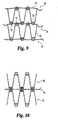
stent 20. Choices of stent include a self expanding stent or a non-self expanding stent. In one embodiment of thepresent invention stent 20 is a self expanding stent such as the Gianturco stent available from Cook Inc. of Bloomington, IN as described inU.S. patent 4,580,568 , the entire disclosure of which is expressly incorporated by reference herein. Such stent can be any length, but in one embodiment, the stent is about 15 mm long.Stent 20 includes a plurality ofbends 22, which generally form the area in which thestent struts 24 reverses direction.Bends 22 are generally rounded to provide an atraumatic condition. Since thestent 20 is generally located in a vessel or body lumen of some type, thestent 20 can be cylindrical and therefore has a stent diameter 21 (shown in FIG. 3). In another embodiment, thestent 20 can also have a plurality ofconnectors 26 that connectadjacent struts 24. One way to provide aconnector 26 is to dispose a solder bead between the adjacent struts. Howeverconnector 26 can also be a suture, weld, adhesive, rod, clamp, or other well-known ways to connectadjacent struts 24.Connector 26 provides several non-critical advantages.Connectors 26 can attachadjacent struts 24 to minimize or prevent flaring of the ends of thestent 20. Furthermore,connector 26, if placed near thebend 22, can create ahole 28 wherein the boundaries of the hole are the wires of the stent operating in general conjunction with theconnector 26. This creates ahole 28 through which a thread or suture can run. However, as shown in FIG. 1C, a separate prefabricated hole can be created by separately attaching a hole assembly, such as acap 29 over thebend 22. In any case, one benefit of theconnector 26 orcap 29 is that they increase the radiographic visualization of the invention. Particularly, if theconnector 26 is a solder bead, it has increased radiopacity. - With respect to FIGs. 2A and 2B, shown is part of the stent in which
connector 26 attachesadjacent struts 24. As mentioned above, a thread or suture can be threaded through thehole 28. Aproximal suture 30 can be sewn through the stentproximal bends 22 or stentproximal ends 31 of the stent. Similarly, adistal suture 32 can be sewn through the stentdistal end 33 or the stentdistal bends 22 of the stent. One way to thread the suture is shown in FIG. 2B wherein the suture 35 (generically any suture) runs over thestrut 24 to enter thehole 28, throughhole 28 to come behind thesame strut 24, over thestrut 24 and across to theadjacent strut 24 running over theadjacent strut 24, behind theadjacent strut 24 to come from behind and throughhole 28, and then run subsequently overadjacent strut 24. Once the struts are connected via the suture, the suture can be pulled to a predetermined tightness to control the overall stent size. Accordingly, the stent can be so constructed to have a predeterminedstent perimeter 34. To this end, thestent lumen 36 will also have an appropriate size. The stent can be constructed so as to have a different perimeter length at the proximal or distal ends. - With regard to FIG. 3, shown is a
cylindrical stent 20 that has the proximal and distal sutures running through thebends 22 orholes 28 of the proximal and distal ends of the stent. By altering the tautness of the sutures, the size of thestent lumen 36, thestent diameter 86, and thestent perimeters 34, can be adjusted. As can be seen,distal perimeter suture 32 runs along the stentdistal end 33, whereasproximal perimeter suture 30 runs along the stent proximal end 31- The respective sutures run throughhole 28 of eachbend 22. - With respect to FIGs. 4 and 5, the
valve material 38 is shown, in this exemplary embodiment, as a sheet. In so constructing thevalve 41, thevalve material 38 is draped across thestent lumen 36 opening (such as shown on the proximal portion of the stent) and then pushed down into thestent lumen 36 itself. Excess material can be kept outside the stent, which will later become a potential fold-over 42. However, the excess material can also be trimmed off. Thevalve material 38 is connected to the stent, using for example, distal valve-stent suture 40. However, any well known ways to connect the valve to the stent is contemplated, such as but not limited to, sutures, adhesives, folds, or the like. In one embodiment shown in FIG. 5, the valve-stent suture 40 can share thehole 28 withdistal suture 32 near thestent perimeter 34. - The
valve material 38 can be any biocompatible material such as polyethylene terephalate (PET), polypropylene (PP), polytetrafluorethylene (PTFE), or any polymer or derivative thereof, and also includes commercially known materials such as GORE-TEX, DACRON, or any other synthetic material. Thepreferred material 38 will be advantageously compliant and employed so as to permit effective value function as described herein and in the case of collapsible/expandable state devices will retain integrity and function when cycled between tehse states. - It is preferred to use a biomaterial that serves as a biocompatible scaffold with the ability to remodel host tissue. Accordingly, a naturally occurring biomaterial is highly desirable. One such biomaterial is collagen and more particularly, a collagen based biomaterial called extracellular matrix (ECM). Examples of ECM's include pericardium, stomach submucosa, liver basement membrane, urinary bladder submucosa, tissue mucosa, dura mater, and small intestine submucosa One such biomaterial is the ECM, such as submucosa, and more particularly is small intestine submucosa (SIS). SIS can be made in the fashion described in
Badylak et al., US Patent 4,902,508 ; Intestinal Collagen Layer described inUS Patent 5,733,337 to Carr and in 17 Nature Biotechnology 1083 (Nov. 1999); Cook et al., WIPO PublicationWO 98/22158, dated 28 May 1998 PCT/US97/14855 WO 98/26291 PCT/US97/22729 US Provisional application-60/032,686 WO 98/25637 PCT/US97/22727 60/032,680 WO 98/25636 PCT/US97/23010 60/032,683 US Patent 5,554,389 ; all the disclosures of which are hereby expressly incorporated by reference. Irrespective of the origin of the valve material (synthetic versus naturally occurring), the valve material can be made thicker by making multilaminate constructs, for example SIS constructs as described inUS Patents 5,968,096 ;5,955,110 ;5,885,619 ; and5,711,969 ; the disclosures of which are entirely and expressly incorporated by reference. - With respect to FIGs. 6A and 6B, shown is the connection of the valve to the stent frame. As described above, the valve can be sutured at the distal portion of the stent using distal valve-
stent suture 40. Similarly, the proximal portion of the valve can be sutured to proximal portion of the stent, and more particularly toproximal perimeter suture 30. Shown is the valve connected to the proximal portion of the stent at proximal valve-stent suture 44.Suture 44 can be through abend 22 or can attach to theproximal perimeter suture 30. In a traditional Gianturco Z-stent, it is either an 8 (bend) point or 10 (bend) point stent, so one leaflet of the valve can be sutured to the four points of an 8 point stent thereby comprising one half of the stent. To provide further integrity, the valve can be sutured at the proximal and distal end to the perimeter sutures themselves, without actually being sutured to any or all of the stent bends 22. - With respect to FIG. 6B, shown is the valve with the stent frame removed. Once the sutures are generally in place, the
valve sheet 38 will form avalve pocket 46, extending inside the stent lumen in which the fluid will fill.Proximal valve perimeter 48 will have the sutures connecting the valve to the stent (not shown). Once the distal sutures are in place, the general shape will likely resemble a pocket with the pocket having avalve apex 50. There is a part of the valve that will formcentral valve portion 49 that is not directly sutured to the stent. This valve portion. 49 will form thevalve opening 52 through which fluid will pass. Thus, upon filling of thevalve pocket 46, the fluid pressure will exert outwards causingvalve portion 49 to extend outward. When it does, it will contact the other leaflets or cusps and form a seal to stop or impede fluid flow. - FIG. 7 shows a top view of the stent valve. In this particular non-limiting view, shown is the
valve opening 52 in a slightly open configuration. Valve pockets 46 are shown in a slightly distended configuration. The valve is connected, for example, by sutures to thestent perimeter 34 and also forms avalve perimeter 48. Because of the opening and closing of the valve, there may be increased wear and tear at the valve-stent-opening connection. At this point, one embodiment of the present invention provides a reinforcement at this point. For example, this reinforcement can be a plurality of reinforcement sutures 54, adhesive, another material, or any other mechanism that permits increased structural integrity. - FIG. 8 demonstrates a view of the stent valve once the distal portion of the valve is sewn to a
distal bend 22 and also shows the proximal portion of the valve being connected to the proximal portion of the frame with one suture in the foreground, one suture in the background. In addition, thereinforcement suture 54 is found in the foreground. Although only twosutures 44 are seen at the proximal portion, it is of course well-understood that some or each of the proximal bend of the frame can be connected to the proximal portion of the valve. Similarly, although only onedistal suture 40 is shown, there may be as many distal sutures necessary to connect thevalve apex 50 or the distal portion of the valve to the frame. It is well understood that this may be just one distal suture or many distal sutures. Varying the number of distal sutures will vary the shape, tightness, and overall configuration of the valve,valve pocket 46, and thevalve apex 50. - The
valve opening 52 although already described above, is actually created in the final step of preparation of the preferred device manufacture. The construction mentioned above would be repeated on the other side of the valve to create thevalve pocket 46,valve apex 50, and the like on the other side. At this point, though, there is novalve opening 52. Thevalve opening 52 is created by creating a slit in the sheet to create the opening. The slit can be sized according to the intended flow rate of the passing fluid. Accordingly, a large slit would create a large valve opening or orifice and permits a large volume of fluid to pass therethrough. The slit can be created by poking a scalpel through it and running it to the desired length. However, due to potential fatigue at the orifice, another set of reinforcements may be added to the orifice perimeter. Therefore, as shown in FIGs. 7 and 8, anorifice reinforcement 53 may be created by any known conventional ways, such as sutures (resorbable or non-resorbable), adhesive, string, staples, rings, or the like. - Therefore, the stent valve as constructed can be using one stent with the valve material enclosed therein. Of course in the single stent configuration, the overall length can be adjusted by elongating the length of the
struts 24. However, devices of the invention can be built using a plurality of stents to elongate the overall size of the stent, if desired. In this regard, it will be preferred that the length of thedevice 20 is sufficient to provide an aspect ratio (length to expanded diameter) sufficiently high to facilitate proper alignment of thedevice 20 within the vessel, with the axis of the device lumen generally aligned with the axis of the vessel. For example, devices having a ratio of length:expanded diameter of 1:1 or greater, or about 2:1 or greater, will be preferred. It will be understood that while such dimensions will advantageously facilitate placement of the inventive devices, they are not necessary to the broader aspects of the invention. - With reference to FIG. 15, shown is a double stent structure with the valve. Returning now to FIG. 9, shown is a
first stent 58 and asecond stent 60. For the purposes of discussion only,first stent 58 is shown to be atop of thesecond stent 60. Ultimately as shown herein by way of example only, the valve will reside in thefirst stent 58. It should be noted however that the valve can reside in thesecond stent 60 also as shown in FIG. 17. Furthermore, the overall length can be increased by joining several stent valves together as shown in FIGs. 18 and 19, thereby having a plurality of stents, such as afirst stent 58,second stent 60, and athird stent 61. Thevalve 41 can be placed in any or all stents, in any combination, for example, as shown by the dotted lines. In this regard, it is suggested and intended that many stents can be joined and that each or any stent may house a valve or plurality of valves. One benefit of having a plurality of stents is that upon ejection of the placement device, the invention will provide a self-aligning feature in the vessel. This is because the plurality of stents is generally longer with respect to the stent diameter, or the plurality of valve device(s), as discussed above. - Manufacture of the multi-stent or multi-valve device will generally follow the same construction as described above. The same considerations in making a single valve single stent device applies equally to the elongated device.
- Returning now to FIGs. 9 and 10, shown are methods of connecting the
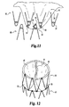
first stent 58 andsecond stent 60. Equally, the construction shown from now on also includes construction of at least two stents or at least two valves.First stent 58 andsecond stent 60 hasbends 22 that are adjacent each other. Shown in FIG. 9 is where thefirst stent 58 has its bends beside the bends of thesecond stent 60 such that they are not touching each other (although they may touch). They are connected together in the manner described above, and for example by stent-stent suture 56. Stent-stent suture 56 can be resorbable or non-resorbable. This suture travels through the distal bends of thefirst stent 56 and the proximal bends of thesecond stent 60. The suturing pattern can be that described in FIG. 2B and the accompanying discussion. As shown in FIG. 10, the bends can be juxtaposed over each other to provide an overlap such that the stent-stent suture 56 will go through the bends at the same time. Therefore, the construction contemplates that the stent bends may touch, overlap, or not at all. - FIG. 11 shows one embodiment of the present invention in which the
valve apex 50 is sutured to at least three bends: two bends of thefirst stent 56 and one bend of thesecond stent 60. In this regard, the valve also operates to keep thefirst stent 56 partially connected to thesecond stent 60. From the bends, a plurality of valve apex sutures 66 are seen. These sutures can emanate from the bends and each bend can have many valve apex sutures 66 that travel in many directions. Using multiple valve apex sutures 66 that emanate in many directions and using a plurality of bends (from either stent), generally functions to minimize any parachuting or inversion of thevalve pocket 46. - FIG. 12 demonstrates a top view of the multi-stent device in which the
valve opening 52 is seen (in a closed position) and thevalve pocket 46 andvalve apex 50 is connected to three bends. Again it should be understood that many sutures may emanate from many bends from any stent. - As described earlier, the excess material can either be trimmed off or folded over the outer surface of the device. Shown in FIGs. 13A and 13B, is the excess material being folded over the device and attached at the distal end of the
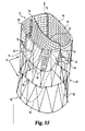
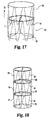
first stent 58. Shown in dotted lines is thefirst stent 58. FIG. 13B shows that the fold-over 42 provides a second material outer sheath so that the suture passes through the inside and outside material to increase structural integrity. Also, by folding over the excess material, a smoother surface is presented rather than the naked frame of the tip of the bend. - In all embodiments of the invention, the external surface of the frame can be covered with a sheath that is not necessarily the same material as the
valve 41. For example, while the valve can be a naturally occurring material, the outer sheath can be synthetic material such as described herein- The sheath, therefore, can be the fold-over of the valve material, another type of naturally occurring material, or a synthetic material. Accordingly, the sheath may partially or totally cover the frame. - FIG. 14 shows an embodiment in which both the
first stent 58 andsecond stent 60 are covered by the fold over 42. Here, the fold-over 42 is connected to the distal portion of thesecond stent 60. In this manner, the entire device may be covered with an outer sheath of biomaterial. The benefit of doing so, especially if using SIS or other similar ECMs, is that the regrowth and endothelialization of the device embeds and encapsulates the frame. Accordingly, there is a reduced risk of device migration. Furthermore, due to the remarkable remodeling properties of SIS, the outer SIS sheath acts as a conduit for host tissue to infiltrate the device and remodel the valve itself. Over the course of months, the valves are replaced by host tissue and the SIS disappears. - FIG. 15 shows yet another embodiment of the present invention. In this demonstration, the valve is located in the
first stent 58, sutured at the proximal end at the stent perimeter. Thevalve apex 50 is sewn somewhat proximal of the stent-stent suture 56. Thevalve apex 50 is sewn at the valve apex sutures 66 to an intermediate portion of the frame. To minimize parachuting or inversion, a valveintermediate portion 75 may be sutured using valveintermediate suture 76 to connect the valve to the frame. In addition, the valve may be so constructed to extend the valve's length to create an elongated valve pocket 90 (shown by the dotted lines). While theextended pocket 90 can be connected to the distal perimeter of the second stentdistal suture 62, it can also be connected to an intermediate portion of the second stent. - With further reference to FIG. 15, it is seen that the
valve opening 52 is a slit that extends across thefirst stent diameter 21 but terminates several millimeters before reaching the edge. In some embodiments, this distance could be 1-5 mm from the edge. Of course, it is understood that the invention contemplates any distance that varies the length of the slit- Also, shown in FIG. 15, but equally applies to any device described herein, is ananchor 92, which can beanchor barbs 92. Thesebarbs 92 can dig into the adjacent vessel wall to relatively affix the device at its location.Anchor 92, although shown as barbs, may include hooks, adhesives, knobs, a textured surface, or any other treated surface that facilitates relative affixation of the device in its location. Similarly, the outer surface of the fold-over or sheath can be so configured to provide anchoring. - FIG. 16 demonstrates the device upon implantation into the patient. Upon implantation the device generally resides in a
vessel 80. For example, the vessel could be vein, artery or the heart or wherever a valve is necessary. In one preferred use, the vessel is an incompetent vein in the leg or foot of a patient. Thedevice 20 reduces or prevents retrograde blood flow, while normal blood flow is permitted to travel throughdevice 20. Illustrative veins in which thedevice 20 may be used include, for example, saphenous veins, femoral veins, popliteal veins, tibial veins, and the inferior vena cava. - The
vessel 80 has an innerlumenal surface 82 in which the fluid flows. The fluid flow path is shown asfluid path 70.Vessel 80 also has avessel diameter 84. The medical device, upon implantation, will also have a deviceouter stent diameter 86. Theouter diameter 86 will be chosen to permit contact with the innerlumenal surface 82. The optimized fit will decrease the leakage around the device by contacting the innerlumenal surface 82. A tight fit can be accomplished by sizing the stent diameter to be greater than the vessel diameter. For example, a stent diameter that is about 110 percent greater than (i.e. 1.1 times) the vessel diameter provides a good fit. Expanded stent diameters of about 10 mm to about 30 mm will be typical in many applications of the present invention. Again, while it is shown in this FIG. 16 that the valve is located in thefirst stent 58 and only thefirst stent 58 is covered by the fold-over 42 or sheath, it should be remembered that the valve could be located in thesecond stent 60. Similarly, the fold-over 42 or sheath could extend onto thesecond stent 60. - The standard method of deploying the
medical device 20 in avessel 80 involves the use of a medical assembly (see FIG. 20) including thedevice 20 and a delivery device such as a percutaneous delivery device, e.g. acatheter 100. The frame is configured to a contracted state, e.g. by resiliently forming the frame into a contracted configuration, to load into the delivery device (catheter). The catheter can be introduced into the patient via a suitable approach, for example through the jugular or femoral vein. To advance and deploy the device from the distal end of the delivery catheter, apusher 101 is placed into the catheter lumen. When thedevice 20 is fully deployed, it assumes the second, expanded configuration within thevessel 80 as depicted in FIG. 16. The stent frame, being made of resilient material, conforms to the shape of the vessel wall such that when viewed on end, thedevice 20 has a circular appearance when deployed in a round vessel. - FIGs. 17. 18, and 19 show other described embodiments. FIG. 17 demonstrates the
valve 41 in thesecond stent 60. In this embodiment, thevalve apex 50 is connected to the second stent's distal perimeter. FIG. 18 demonstrates at least two stent frames connected together. In this particular embodiment, the valve is located in thefirst stent 58, with thevalve apex 50 being connected at the first stent 58-second stent 60 junction. In dotted lines, however, there may be many stents, such asfirst stent 58,second stent 60, andthird stent 61. Thevalve 41 may be found in any of the stents or in all. Similarly, in the three stent configuration, the valve may begin at the first stent and have thevalve apex 50 be generally located in thethird stent 61. FIG. 19 shows another embodiment of the present invention in which thevalve 41 begins in thesecond stent 60 and extends into thethird stent 61 thereby having thefirst stent 58 being empty. - Finally, since the device is located in an in vivo environment, the device may be treated with therapeutic agents to facilitate healing. For example, the frame may be treated with therapeutic agents such as anti-cancer drugs, plaque busters, anti-coagulants, or the like. Similarly, the valve material can be treated with therapeutics agents such as anti-cancer drugs, plaque busters, anti-coagulants, proteins, growth factors, proteoglycans, and the like. Furthermore, radiopaque agents may be added, such as tantalum, barium, bismuth, or the like to increase radiopacity. These ingredients can be bonded to the frame or the valve material such as rubbing the agent in, bonding it, adhering it, or the like.
- While the invention has been illustrated and described in detail in the drawings and the foregoing text, it is understood that these are only some embodiments and that the scope of the invention is not solely defined by the description herein but also by the appended claims. All modifications and changes that come within the spirit of the invention are hereby protected.
Claims (37)
- A stent valve, suitable for placement in a vessel, the vessel further having a diameter and an inner lumenal surface, comprising:a) a stent having a diameter, a proximal end, and a distal end, the stent sized to permit contact with the inner lumenal surface of the vessel;b) a valve having a proximal end and a distal end, the valve being at least partially located within an inner portion of the stent, wherein the valve comprises a biocompatible material.
- The stent valve of claim 1, wherein the stent is a self-expanding stent.
- The stent valve of claim 1, wherein a sheath partially covers the stent.
- The stent valve of claim 3, wherein the sheath further comprises substantially biocompatible material.
- The stent valve of claim 4, wherein the stent is a self-expanding stent.
- The stent valve of claim 1, wherein the stent has a diameter greater than the vessel diameter.
- The stent valve of claim 6, wherein the stent has a diameter 110 percent greater than the vessel diameter.
- The stent valve of claim 6, wherein a sheath partially covers the stent.
- The stent valve of claim 8, wherein the sheath comprises a biological material.
- The stent valve of claim 9, wherein the sheath comprises tissue submucosa.
- The stent valve of claim 10, wherein the submucosa further comprises at least one of a gastric, liver, intestinal, urinary, stomach, and genito-urinary tissue.
- The stent valve of claim 1, wherein the valve further comprises at least one leaflet, wherein the at least one leaflet is capable of preventing a backflow of blood.
- The stent valve of claim 1, wherein the valve proximal end is connected to the stent proximal end.
- The stent valve of claim 13, wherein the valve proximal end is sutured to the stent proximal end.
- The stent valve of claim 13, wherein the valve proximal end is sutured at least 4 times to the stent proximal end.
- The stent valve of claim 13, wherein the valve proximal end is sutured at least 7 times to the stent proximal end.
- The stent valve of claim 1, wherein the valve distal end is connected to the stent distal end.
- The stent valve of claim 1, wherein the valve distal end is sutured to the stent distal end.
- The stent valve of claim 18, wherein the valve distal end is sutured at least 2 times to the stent distal end.
- The stent valve of claim 18, wherein the valve distal end is sutured at least 3 times to the stent distal end.
- The stent valve of claim 1, wherein an intermediate portion of the valve is connected to an intermediate portion of the stent.
- The stent valve of claim 1, wherein an intermediate portion of the valve is connected to the stent distal end.
- The stent valve of claim 1, wherein a valve opening extends substantially across the stent diameter.
- The stent valve of claim 23, wherein the valve opening terminates at least 1 mm from a stent perimeter.
- The stent valve of claim 23, wherein a reinforcement
is generally located at a valve opening and a stent perimeter. - The stent valve of claim 1, wherein said stent is a
radially expandable stent, said radially expandable stent having a first configuration adapted for delivery through a lumen of a delivery device, and a second configuration for conforming to an interior wall of a body vessel. - The stent device of claim 26, wherein the body vessel
is a vein. - A medical device, suitable for placement in a vessel,
the vessel further having a diameter and an inner lumenal surface, comprising:a) at least one stent, the at least one stent having a proximal end, a distal end, and a lumen extending therethrough;b) a valve having a proximal end and a distal end, the valve generally located within the lumen of the at least one stent;c) the valve distal end being secured to an intermediate portion of the at least one stent; andd) the valve further comprising a biological material. - A medical device, suitable for placement in a vessel, the vessel further having a diameter and an inner lumenal surface, comprising:a) at least one stent, the at least one stent having a proximal end, a distal end, and a lumen extending therethrough;b) a valve having a proximal end and a distal end, the valve generally located within the lumen of the at least one stent;c) the valve distal end being secured to an intermediate portion of the at least one stent; andd) the valve further having a valve opening, the valve opening also further comprising a reinforcement disposed on the valve opening.
- A medical device, suitable for placement in a vessel, the vessel further having a diameter and an inner lumenal surface, comprising:a) at least one stent, the at least one stent having a proximal end, a distal end, and a lumen extending therethrough;b) at least one valve having a proximal end and a distal end, the valve generally located within the lumen of the at least one stentc) the at least one valve distal end being partially secured to an inner portion of the at least one stent; andd) the valve further comprising a biological material.
- A radially-expandable stent valve device for placement in a body vessel, comprising:a self-expanding stent frame, said self-expanding stent frame conformable to a first, contracted state adapted for delivery through a lumen of a delivery device, and a second, expanded state for conforming a lumen of the vessel;a valve attached to said frame and functional to resist fluid flow in a first direction through said stent frame and permit fluid flow in a second direction through said stent frame opposite said first direction;said valve comprising a compliant biocompatible material defining at least one pocket member within said frame, said pocket member having an opening for receiving fluid flowing in said first direction and adapted to thereupon expand, said pocket member further adapted to contract upon impingement with fluid flowing in said second direction; andsaid biocompatible material sufficiently compliant and said pocket member defined wherein said valve remains functional after contraction of said stent frame to said first, contracted state and expansion of said stent frame to said second, expanded state.
- The stent valve device of claim 31, wherein said valve comprises at least two of said pocket members.
- A medical assembly, comprising a stent valve device of any of claims 2, 5, 26 and 29 received within a lumen of a delivery device.
- A method for providing a valve in a body lumen, comprising:providing a delivery device having a lumen having received therein a stent valve device of any of claims 2, 5, 26 and 29;deploying said stent valve device from said delivery device within said body lumen.
- The method of claim 34, wherein said body lumen is a venous lumen.
- The method of claim 35, wherein said venous lumen is within a vein selected from a saphenous vein, a popliteal vein, a femoral vein, a tibial vein, and the inferior vena cava.
- A medical device, comprising:a valve found generally within a frame;wherein said frame is comprised of a radially-expandable stent which can be delivered through a delivery device and expanded at a target site in a body lumen.
Priority Applications (1)
| Application Number | Priority Date | Filing Date | Title |
|---|---|---|---|
| EP10012515.2A EP2329796B1 (en) | 2000-01-31 | 2001-01-31 | Stent valve |
Applications Claiming Priority (2)
| Application Number | Priority Date | Filing Date | Title |
|---|---|---|---|
| US17919500P | 2000-01-31 | 2000-01-31 | |
| EP01905265A EP1255510B3 (en) | 2000-01-31 | 2001-01-31 | Stent valves |
Related Parent Applications (2)
| Application Number | Title | Priority Date | Filing Date |
|---|---|---|---|
| EP01905265A Division EP1255510B3 (en) | 2000-01-31 | 2001-01-31 | Stent valves |
| EP01905265A Division-Into EP1255510B3 (en) | 2000-01-31 | 2001-01-31 | Stent valves |
Related Child Applications (3)
| Application Number | Title | Priority Date | Filing Date |
|---|---|---|---|
| EP10012515.2A Division EP2329796B1 (en) | 2000-01-31 | 2001-01-31 | Stent valve |
| EP10012515.2A Division-Into EP2329796B1 (en) | 2000-01-31 | 2001-01-31 | Stent valve |
| EP10013161 Division-Into | 2010-10-01 |
Publications (3)
| Publication Number | Publication Date |
|---|---|
| EP1900343A2 true EP1900343A2 (en) | 2008-03-19 |
| EP1900343A3 EP1900343A3 (en) | 2008-03-26 |
| EP1900343B1 EP1900343B1 (en) | 2015-10-21 |
Family
ID=39079533
Family Applications (1)
| Application Number | Title | Priority Date | Filing Date |
|---|---|---|---|
| EP07008364.7A Revoked EP1900343B1 (en) | 2000-01-31 | 2001-01-31 | Stent valves |
Country Status (1)
| Country | Link |
|---|---|
| EP (1) | EP1900343B1 (en) |
Cited By (28)
| Publication number | Priority date | Publication date | Assignee | Title |
|---|---|---|---|---|
| US7704222B2 (en) | 1998-09-10 | 2010-04-27 | Jenavalve Technology, Inc. | Methods and conduits for flowing blood from a heart chamber to a blood vessel |
| US7896915B2 (en) | 2007-04-13 | 2011-03-01 | Jenavalve Technology, Inc. | Medical device for treating a heart valve insufficiency |
| US8062355B2 (en) | 2005-11-04 | 2011-11-22 | Jenavalve Technology, Inc. | Self-expandable medical instrument for treating defects in a patient's heart |
| US8206437B2 (en) | 2001-08-03 | 2012-06-26 | Philipp Bonhoeffer | Implant implantation unit and procedure for implanting the unit |
| US8317858B2 (en) | 2008-02-26 | 2012-11-27 | Jenavalve Technology, Inc. | Stent for the positioning and anchoring of a valvular prosthesis in an implantation site in the heart of a patient |
| US8398704B2 (en) | 2008-02-26 | 2013-03-19 | Jenavalve Technology, Inc. | Stent for the positioning and anchoring of a valvular prosthesis in an implantation site in the heart of a patient |
| US8465540B2 (en) | 2008-02-26 | 2013-06-18 | Jenavalve Technology, Inc. | Stent for the positioning and anchoring of a valvular prosthesis |
| US8468667B2 (en) | 2009-05-15 | 2013-06-25 | Jenavalve Technology, Inc. | Device for compressing a stent |
| US8679174B2 (en) | 2005-01-20 | 2014-03-25 | JenaValve Technology, GmbH | Catheter for the transvascular implantation of prosthetic heart valves |
| USRE45130E1 (en) | 2000-02-28 | 2014-09-09 | Jenavalve Technology Gmbh | Device for fastening and anchoring cardiac valve prostheses |
| US8834561B2 (en) | 2005-10-28 | 2014-09-16 | Jenavalve Technology Gmbh | Device for the implantation and fixation of prosthetic valves |
| US9044318B2 (en) | 2008-02-26 | 2015-06-02 | Jenavalve Technology Gmbh | Stent for the positioning and anchoring of a valvular prosthesis |
| US9138315B2 (en) | 2007-04-13 | 2015-09-22 | Jenavalve Technology Gmbh | Medical device for treating a heart valve insufficiency or stenosis |
| EP1900343B1 (en) | 2000-01-31 | 2015-10-21 | Cook Biotech Incorporated | Stent valves |
| US9168130B2 (en) | 2008-02-26 | 2015-10-27 | Jenavalve Technology Gmbh | Stent for the positioning and anchoring of a valvular prosthesis in an implantation site in the heart of a patient |
| US9295551B2 (en) | 2007-04-13 | 2016-03-29 | Jenavalve Technology Gmbh | Methods of implanting an endoprosthesis |
| US9510947B2 (en) | 2011-10-21 | 2016-12-06 | Jenavalve Technology, Inc. | Catheter system for introducing an expandable heart valve stent into the body of a patient |
| US9597182B2 (en) | 2010-05-20 | 2017-03-21 | Jenavalve Technology Inc. | Catheter system for introducing an expandable stent into the body of a patient |
| US9744031B2 (en) | 2010-05-25 | 2017-08-29 | Jenavalve Technology, Inc. | Prosthetic heart valve and endoprosthesis comprising a prosthetic heart valve and a stent |
| US9839515B2 (en) | 2005-12-22 | 2017-12-12 | Symetis, SA | Stent-valves for valve replacement and associated methods and systems for surgery |
| US9867694B2 (en) | 2013-08-30 | 2018-01-16 | Jenavalve Technology Inc. | Radially collapsible frame for a prosthetic valve and method for manufacturing such a frame |
| US9867699B2 (en) | 2008-02-26 | 2018-01-16 | Jenavalve Technology, Inc. | Endoprosthesis for implantation in the heart of a patient |
| US9878127B2 (en) | 2012-05-16 | 2018-01-30 | Jenavalve Technology, Inc. | Catheter delivery system for heart valve prosthesis |
| US10709555B2 (en) | 2015-05-01 | 2020-07-14 | Jenavalve Technology, Inc. | Device and method with reduced pacemaker rate in heart valve replacement |
| US10973640B2 (en) | 2015-12-03 | 2021-04-13 | Medtronic Vascular, Inc. | Venous valve prostheses |
| US11065138B2 (en) | 2016-05-13 | 2021-07-20 | Jenavalve Technology, Inc. | Heart valve prosthesis delivery system and method for delivery of heart valve prosthesis with introducer sheath and loading system |
| US11197754B2 (en) | 2017-01-27 | 2021-12-14 | Jenavalve Technology, Inc. | Heart valve mimicry |
| US11278406B2 (en) | 2010-05-20 | 2022-03-22 | Jenavalve Technology, Inc. | Catheter system for introducing an expandable heart valve stent into the body of a patient, insertion system with a catheter system and medical device for treatment of a heart valve defect |
Families Citing this family (15)
| Publication number | Priority date | Publication date | Assignee | Title |
|---|---|---|---|---|
| US8579964B2 (en) | 2010-05-05 | 2013-11-12 | Neovasc Inc. | Transcatheter mitral valve prosthesis |
| US9554897B2 (en) | 2011-04-28 | 2017-01-31 | Neovasc Tiara Inc. | Methods and apparatus for engaging a valve prosthesis with tissue |
| US9308087B2 (en) | 2011-04-28 | 2016-04-12 | Neovasc Tiara Inc. | Sequentially deployed transcatheter mitral valve prosthesis |
| US9345573B2 (en) | 2012-05-30 | 2016-05-24 | Neovasc Tiara Inc. | Methods and apparatus for loading a prosthesis onto a delivery system |
| US9572665B2 (en) | 2013-04-04 | 2017-02-21 | Neovasc Tiara Inc. | Methods and apparatus for delivering a prosthetic valve to a beating heart |
| US9700409B2 (en) | 2013-11-06 | 2017-07-11 | St. Jude Medical, Cardiology Division, Inc. | Reduced profile prosthetic heart valve |
| US10433952B2 (en) | 2016-01-29 | 2019-10-08 | Neovasc Tiara Inc. | Prosthetic valve for avoiding obstruction of outflow |
| US10098740B2 (en) | 2016-07-15 | 2018-10-16 | Covidien Lp | Venous valve prostheses |
| AU2017361296B2 (en) | 2016-11-21 | 2022-09-29 | Neovasc Tiara Inc. | Methods and systems for rapid retraction of a transcatheter heart valve delivery system |
| US10856984B2 (en) | 2017-08-25 | 2020-12-08 | Neovasc Tiara Inc. | Sequentially deployed transcatheter mitral valve prosthesis |
| CA3118599A1 (en) | 2018-11-08 | 2020-05-14 | Neovasc Tiara Inc. | Ventricular deployment of a transcatheter mitral valve prosthesis |
| US11602429B2 (en) | 2019-04-01 | 2023-03-14 | Neovasc Tiara Inc. | Controllably deployable prosthetic valve |
| AU2020271896B2 (en) | 2019-04-10 | 2022-10-13 | Neovasc Tiara Inc. | Prosthetic valve with natural blood flow |
| EP3972673A4 (en) | 2019-05-20 | 2023-06-07 | Neovasc Tiara Inc. | Introducer with hemostasis mechanism |
| WO2020257643A1 (en) | 2019-06-20 | 2020-12-24 | Neovasc Tiara Inc. | Low profile prosthetic mitral valve |
Citations (5)
| Publication number | Priority date | Publication date | Assignee | Title |
|---|---|---|---|---|
| US5480424A (en) | 1993-11-01 | 1996-01-02 | Cox; James L. | Heart valve replacement using flexible tubes |
| US5545214A (en) | 1991-07-16 | 1996-08-13 | Heartport, Inc. | Endovascular aortic valve replacement |
| WO1998029057A1 (en) | 1996-12-31 | 1998-07-09 | Cordis Corporation | Valve prosthesis for implantation in body channels |
| US5855597A (en) | 1997-05-07 | 1999-01-05 | Iowa-India Investments Co. Limited | Stent valve and stent graft for percutaneous surgery |
| DE19904975A1 (en) | 1999-02-06 | 2000-09-14 | Impella Cardiotech Ag | Device for intravascular heart valve surgery |
Family Cites Families (15)
| Publication number | Priority date | Publication date | Assignee | Title |
|---|---|---|---|---|
| US179195A (en) | 1876-06-27 | Improvement in curry-combs | ||
| US4172295A (en) | 1978-01-27 | 1979-10-30 | Shiley Scientific, Inc. | Tri-cuspid three-tissue prosthetic heart valve |
| US4388735A (en) | 1980-11-03 | 1983-06-21 | Shiley Inc. | Low profile prosthetic xenograft heart valve |
| US4580568A (en) | 1984-10-01 | 1986-04-08 | Cook, Incorporated | Percutaneous endovascular stent and method for insertion thereof |
| US5411552A (en) | 1990-05-18 | 1995-05-02 | Andersen; Henning R. | Valve prothesis for implantation in the body and a catheter for implanting such valve prothesis |
| US5861028A (en) | 1996-09-09 | 1999-01-19 | Shelhigh Inc | Natural tissue heart valve and stent prosthesis and method for making the same |
| DE69719237T2 (en) * | 1996-05-23 | 2003-11-27 | Samsung Electronics Co Ltd | Flexible, self-expandable stent and method for its manufacture |
| US5855601A (en) | 1996-06-21 | 1999-01-05 | The Trustees Of Columbia University In The City Of New York | Artificial heart valve and method and device for implanting the same |
| NL1004827C2 (en) | 1996-12-18 | 1998-06-19 | Surgical Innovations Vof | Device for regulating blood circulation. |
| US5925063A (en) * | 1997-09-26 | 1999-07-20 | Khosravi; Farhad | Coiled sheet valve, filter or occlusive device and methods of use |
| US5910170A (en) | 1997-12-17 | 1999-06-08 | St. Jude Medical, Inc. | Prosthetic heart valve stent utilizing mounting clips |
| CA2361670C (en) | 1999-01-27 | 2010-03-30 | Viacor Incorporated | Cardiac valve procedure methods and devices |
| JP4409803B2 (en) | 1999-09-10 | 2010-02-03 | クック・インコーポレイテッド | Valve assembly for use in a lumen of a vessel and method for making the valve assembly |
| EP1900343B1 (en) | 2000-01-31 | 2015-10-21 | Cook Biotech Incorporated | Stent valves |
| PL211860B1 (en) | 2000-01-31 | 2012-07-31 | Cook Biotech Inc | Valve stent system |
-
2001
- 2001-01-31 EP EP07008364.7A patent/EP1900343B1/en not_active Revoked
Patent Citations (5)
| Publication number | Priority date | Publication date | Assignee | Title |
|---|---|---|---|---|
| US5545214A (en) | 1991-07-16 | 1996-08-13 | Heartport, Inc. | Endovascular aortic valve replacement |
| US5480424A (en) | 1993-11-01 | 1996-01-02 | Cox; James L. | Heart valve replacement using flexible tubes |
| WO1998029057A1 (en) | 1996-12-31 | 1998-07-09 | Cordis Corporation | Valve prosthesis for implantation in body channels |
| US5855597A (en) | 1997-05-07 | 1999-01-05 | Iowa-India Investments Co. Limited | Stent valve and stent graft for percutaneous surgery |
| DE19904975A1 (en) | 1999-02-06 | 2000-09-14 | Impella Cardiotech Ag | Device for intravascular heart valve surgery |
Cited By (80)
| Publication number | Priority date | Publication date | Assignee | Title |
|---|---|---|---|---|
| US8216174B2 (en) | 1998-09-10 | 2012-07-10 | Jenavalve Technology, Inc. | Methods and conduits for flowing blood from a heart chamber to a blood vessel |
| US7736327B2 (en) | 1998-09-10 | 2010-06-15 | Jenavalve Technology, Inc. | Methods and conduits for flowing blood from a heart chamber to a blood vessel |
| US8597226B2 (en) | 1998-09-10 | 2013-12-03 | Jenavalve Technology, Inc. | Methods and conduits for flowing blood from a heart chamber to a blood vessel |
| US7704222B2 (en) | 1998-09-10 | 2010-04-27 | Jenavalve Technology, Inc. | Methods and conduits for flowing blood from a heart chamber to a blood vessel |
| EP1900343B1 (en) | 2000-01-31 | 2015-10-21 | Cook Biotech Incorporated | Stent valves |
| USRE45130E1 (en) | 2000-02-28 | 2014-09-09 | Jenavalve Technology Gmbh | Device for fastening and anchoring cardiac valve prostheses |
| US8216301B2 (en) | 2001-08-03 | 2012-07-10 | Philipp Bonhoeffer | Implant implantation unit |
| US8585756B2 (en) | 2001-08-03 | 2013-11-19 | Jenavalve Technology, Inc. | Methods of treating valves |
| US8303653B2 (en) | 2001-08-03 | 2012-11-06 | Philipp Bonhoeffer | Implant implantation unit and procedure for implanting the unit |
| US9949824B2 (en) | 2001-08-03 | 2018-04-24 | Jenavalve Technology, Inc. | Devices useful for implantation at a heart valve |
| US9889002B2 (en) | 2001-08-03 | 2018-02-13 | Jenavalve Technology, Inc. | Devices useful for implantation at a heart valve |
| US8206437B2 (en) | 2001-08-03 | 2012-06-26 | Philipp Bonhoeffer | Implant implantation unit and procedure for implanting the unit |
| US11007052B2 (en) | 2001-08-03 | 2021-05-18 | Jenavalve Technology, Inc. | Devices useful for implantation at a heart valve |
| US8579965B2 (en) | 2001-08-03 | 2013-11-12 | Jenavalve Technology, Inc. | Methods of implanting an implantation device |
| US10492906B2 (en) | 2005-01-20 | 2019-12-03 | Jenavalve Technology, Inc. | Catheter system for implantation of prosthetic heart valves |
| US9788945B2 (en) | 2005-01-20 | 2017-10-17 | Jenavalve Technology, Inc. | Systems for implanting an endoprosthesis |
| US8679174B2 (en) | 2005-01-20 | 2014-03-25 | JenaValve Technology, GmbH | Catheter for the transvascular implantation of prosthetic heart valves |
| US9775705B2 (en) | 2005-01-20 | 2017-10-03 | Jenavalve Technology, Inc. | Methods of implanting an endoprosthesis |
| US11517431B2 (en) | 2005-01-20 | 2022-12-06 | Jenavalve Technology, Inc. | Catheter system for implantation of prosthetic heart valves |
| US9855142B2 (en) | 2005-10-28 | 2018-01-02 | JenaValve Technologies, Inc. | Device for the implantation and fixation of prosthetic valves |
| USRE45962E1 (en) | 2005-10-28 | 2016-04-05 | Jenavalve Technology Gmbh | Device for the implantation and fixation of prosthetic valves |
| US10363134B2 (en) | 2005-10-28 | 2019-07-30 | Jenavalve Technology, Inc. | Device for the implantation and fixation of prosthetic valves |
| US9044320B2 (en) | 2005-10-28 | 2015-06-02 | Jenavalve Technology Gmbh | Device for the implantation and fixation of prosthetic valves |
| US8834561B2 (en) | 2005-10-28 | 2014-09-16 | Jenavalve Technology Gmbh | Device for the implantation and fixation of prosthetic valves |
| US9402717B2 (en) | 2005-10-28 | 2016-08-02 | Jenavalve Technology, Inc. | Device for the implantation and fixation of prosthetic valves |
| US11116628B2 (en) | 2005-10-28 | 2021-09-14 | Jenavalve Technology, Inc. | Device for the implantation and fixation of prosthetic valves |
| USRE45790E1 (en) | 2005-10-28 | 2015-11-03 | Jenavalve Technology Gmbh | Device for the implantation and fixation of prosthetic valves |
| US8062355B2 (en) | 2005-11-04 | 2011-11-22 | Jenavalve Technology, Inc. | Self-expandable medical instrument for treating defects in a patient's heart |
| US10314701B2 (en) | 2005-12-22 | 2019-06-11 | Symetis Sa | Stent-valves for valve replacement and associated methods and systems for surgery |
| US10265167B2 (en) | 2005-12-22 | 2019-04-23 | Symetis Sa | Stent-valves for valve replacement and associated methods and systems for surgery |
| US9839515B2 (en) | 2005-12-22 | 2017-12-12 | Symetis, SA | Stent-valves for valve replacement and associated methods and systems for surgery |
| US10299922B2 (en) | 2005-12-22 | 2019-05-28 | Symetis Sa | Stent-valves for valve replacement and associated methods and systems for surgery |
| US11357624B2 (en) | 2007-04-13 | 2022-06-14 | Jenavalve Technology, Inc. | Medical device for treating a heart valve insufficiency |
| US9445896B2 (en) | 2007-04-13 | 2016-09-20 | Jenavalve Technology, Inc. | Methods for treating a heart valve insufficiency or stenosis |
| US10543084B2 (en) | 2007-04-13 | 2020-01-28 | Jenavalve Technology, Inc. | Medical device for treating a heart valve insufficiency |
| US9918835B2 (en) | 2007-04-13 | 2018-03-20 | Jenavalve Technology, Inc. | Medical device for treating a heart valve insufficency |
| US7896915B2 (en) | 2007-04-13 | 2011-03-01 | Jenavalve Technology, Inc. | Medical device for treating a heart valve insufficiency |
| US9138315B2 (en) | 2007-04-13 | 2015-09-22 | Jenavalve Technology Gmbh | Medical device for treating a heart valve insufficiency or stenosis |
| US8685085B2 (en) | 2007-04-13 | 2014-04-01 | JenaValve Technologies GmbH | Medical device for treating a heart valve insufficiency |
| US9295551B2 (en) | 2007-04-13 | 2016-03-29 | Jenavalve Technology Gmbh | Methods of implanting an endoprosthesis |
| US9339386B2 (en) | 2007-04-13 | 2016-05-17 | Jenavalve Technology, Inc. | Medical device for treating a heart valve insufficency |
| US7914575B2 (en) | 2007-04-13 | 2011-03-29 | Jenavalve Technology, Inc. | Medical device for treating a heart valve insufficiency |
| US10993805B2 (en) | 2008-02-26 | 2021-05-04 | Jenavalve Technology, Inc. | Stent for the positioning and anchoring of a valvular prosthesis in an implantation site in the heart of a patient |
| US11154398B2 (en) | 2008-02-26 | 2021-10-26 | JenaValve Technology. Inc. | Stent for the positioning and anchoring of a valvular prosthesis in an implantation site in the heart of a patient |
| US9877828B2 (en) | 2008-02-26 | 2018-01-30 | Jenavalve Technology, Inc. | Stent for the positioning and anchoring of a valvular prosthesis in an implantation site in the heart of a patient |
| US11564794B2 (en) | 2008-02-26 | 2023-01-31 | Jenavalve Technology, Inc. | Stent for the positioning and anchoring of a valvular prosthesis in an implantation site in the heart of a patient |
| US8398704B2 (en) | 2008-02-26 | 2013-03-19 | Jenavalve Technology, Inc. | Stent for the positioning and anchoring of a valvular prosthesis in an implantation site in the heart of a patient |
| US9044318B2 (en) | 2008-02-26 | 2015-06-02 | Jenavalve Technology Gmbh | Stent for the positioning and anchoring of a valvular prosthesis |
| US8317858B2 (en) | 2008-02-26 | 2012-11-27 | Jenavalve Technology, Inc. | Stent for the positioning and anchoring of a valvular prosthesis in an implantation site in the heart of a patient |
| US9987133B2 (en) | 2008-02-26 | 2018-06-05 | Jenavalve Technology, Inc. | Stent for the positioning and anchoring of a valvular prosthesis in an implantation site in the heart of a patient |
| US10154901B2 (en) | 2008-02-26 | 2018-12-18 | Jenavalve Technology, Inc. | Stent for the positioning and anchoring of a valvular prosthesis in an implantation site in the heart of a patient |
| US8465540B2 (en) | 2008-02-26 | 2013-06-18 | Jenavalve Technology, Inc. | Stent for the positioning and anchoring of a valvular prosthesis |
| US8790395B2 (en) | 2008-02-26 | 2014-07-29 | Jenavalve Technology Gmbh | Stent for the positioning and anchoring of a valvular prosthesis in an implantation site in the heart of a patient |
| US9867699B2 (en) | 2008-02-26 | 2018-01-16 | Jenavalve Technology, Inc. | Endoprosthesis for implantation in the heart of a patient |
| US9168130B2 (en) | 2008-02-26 | 2015-10-27 | Jenavalve Technology Gmbh | Stent for the positioning and anchoring of a valvular prosthesis in an implantation site in the heart of a patient |
| US9707075B2 (en) | 2008-02-26 | 2017-07-18 | Jenavalve Technology, Inc. | Endoprosthesis for implantation in the heart of a patient |
| US9265631B2 (en) | 2008-02-26 | 2016-02-23 | Jenavalve Technology, Inc. | Stent for the positioning and anchoring of a valvular prosthesis in an implantation site in the heart of a patient |
| US9439759B2 (en) | 2008-02-26 | 2016-09-13 | Jenavalve Technology, Inc. | Endoprosthesis for implantation in the heart of a patient |
| US10702382B2 (en) | 2008-02-26 | 2020-07-07 | Jenavalve Technology, Inc. | Stent for the positioning and anchoring of a valvular prosthesis in an implantation site in the heart of a patient |
| US10575947B2 (en) | 2008-02-26 | 2020-03-03 | Jenavalve Technology, Inc. | Stent for the positioning and anchoring of a valvular prosthesis in an implantation site in the heart of a patient |
| US8468667B2 (en) | 2009-05-15 | 2013-06-25 | Jenavalve Technology, Inc. | Device for compressing a stent |
| US9597182B2 (en) | 2010-05-20 | 2017-03-21 | Jenavalve Technology Inc. | Catheter system for introducing an expandable stent into the body of a patient |
| US11147669B2 (en) | 2010-05-20 | 2021-10-19 | Jenavalve Technology, Inc. | Catheter system for introducing an expandable stent into the body of a patient |
| US10307251B2 (en) | 2010-05-20 | 2019-06-04 | Jenavalve Technology, Inc. | Catheter system for introducing an expandable stent into the body of a patient |
| US10856978B2 (en) | 2010-05-20 | 2020-12-08 | Jenavalve Technology, Inc. | Catheter system |
| US11278406B2 (en) | 2010-05-20 | 2022-03-22 | Jenavalve Technology, Inc. | Catheter system for introducing an expandable heart valve stent into the body of a patient, insertion system with a catheter system and medical device for treatment of a heart valve defect |
| US10603164B2 (en) | 2010-05-25 | 2020-03-31 | Jenavalve Technology, Inc. | Prosthetic heart valve and endoprosthesis comprising a prosthetic heart valve and a stent |
| US11589981B2 (en) | 2010-05-25 | 2023-02-28 | Jenavalve Technology, Inc. | Prosthetic heart valve and transcatheter delivered endoprosthesis comprising a prosthetic heart valve and a stent |
| US9744031B2 (en) | 2010-05-25 | 2017-08-29 | Jenavalve Technology, Inc. | Prosthetic heart valve and endoprosthesis comprising a prosthetic heart valve and a stent |
| US9510947B2 (en) | 2011-10-21 | 2016-12-06 | Jenavalve Technology, Inc. | Catheter system for introducing an expandable heart valve stent into the body of a patient |
| US9878127B2 (en) | 2012-05-16 | 2018-01-30 | Jenavalve Technology, Inc. | Catheter delivery system for heart valve prosthesis |
| US10433954B2 (en) | 2013-08-30 | 2019-10-08 | Jenavalve Technology, Inc. | Radially collapsible frame for a prosthetic valve and method for manufacturing such a frame |
| US9867694B2 (en) | 2013-08-30 | 2018-01-16 | Jenavalve Technology Inc. | Radially collapsible frame for a prosthetic valve and method for manufacturing such a frame |
| US11185405B2 (en) | 2013-08-30 | 2021-11-30 | Jenavalve Technology, Inc. | Radially collapsible frame for a prosthetic valve and method for manufacturing such a frame |
| US11337800B2 (en) | 2015-05-01 | 2022-05-24 | Jenavalve Technology, Inc. | Device and method with reduced pacemaker rate in heart valve replacement |
| US10709555B2 (en) | 2015-05-01 | 2020-07-14 | Jenavalve Technology, Inc. | Device and method with reduced pacemaker rate in heart valve replacement |
| US11684476B2 (en) | 2015-12-03 | 2023-06-27 | Medtronic Vascular, Inc. | Venous valve prostheses |
| US10973640B2 (en) | 2015-12-03 | 2021-04-13 | Medtronic Vascular, Inc. | Venous valve prostheses |
| US11065138B2 (en) | 2016-05-13 | 2021-07-20 | Jenavalve Technology, Inc. | Heart valve prosthesis delivery system and method for delivery of heart valve prosthesis with introducer sheath and loading system |
| US11197754B2 (en) | 2017-01-27 | 2021-12-14 | Jenavalve Technology, Inc. | Heart valve mimicry |
Also Published As
| Publication number | Publication date |
|---|---|
| EP1900343B1 (en) | 2015-10-21 |
| EP1900343A3 (en) | 2008-03-26 |
Similar Documents
| Publication | Publication Date | Title |
|---|---|---|
| CA2661804C (en) | Stent valves and uses of same | |
| EP1900343B1 (en) | Stent valves | |
| US9421096B2 (en) | Artificial valve prosthesis with improved flow dynamics | |
| US7267686B2 (en) | Implantable prosthetic valve | |
| US20050182483A1 (en) | Percutaneously placed prosthesis with thromboresistant valve portion | |
| US20070106372A1 (en) | Implantable medical device with constrained expansion | |
| CN107205822A (en) | Integrated valve assemblies and delivering and the method for the integrated valve assemblies of deployment | |
| CN111698967B (en) | Expandable frame and paravalvular leak mitigation system for implantable prosthetic heart valve devices | |
| AU2013263836B2 (en) | Stent valves and uses of same | |
| AU2012244361B2 (en) | Stent valves and uses of same | |
| AU2008200570B2 (en) | Endoluminal cardiac and venous valve prostheses and methods of manufacture and delivery thereof |
Legal Events
| Date | Code | Title | Description |
|---|---|---|---|
| PUAI | Public reference made under article 153(3) epc to a published international application that has entered the european phase |
Free format text: ORIGINAL CODE: 0009012 |
|
| PUAL | Search report despatched |
Free format text: ORIGINAL CODE: 0009013 |
|
| AC | Divisional application: reference to earlier application |
Ref document number: 1255510 Country of ref document: EP Kind code of ref document: P |
|
| AK | Designated contracting states |
Kind code of ref document: A2 Designated state(s): AT BE CH CY DE DK ES FI FR GB GR IE IT LI LU MC NL PT SE TR |
|
| AK | Designated contracting states |
Kind code of ref document: A3 Designated state(s): AT BE CH CY DE DK ES FI FR GB GR IE IT LI LU MC NL PT SE TR |
|
| 17P | Request for examination filed |
Effective date: 20080924 |
|
| 17Q | First examination report despatched |
Effective date: 20081104 |
|
| AKX | Designation fees paid |
Designated state(s): AT BE CH CY DE DK ES FI FR GB GR IE IT LI LU MC NL PT SE TR |
|
| TPAC | Observations filed by third parties |
Free format text: ORIGINAL CODE: EPIDOSNTIPA |
|
| GRAP | Despatch of communication of intention to grant a patent |
Free format text: ORIGINAL CODE: EPIDOSNIGR1 |
|
| INTG | Intention to grant announced |
Effective date: 20150522 |
|
| RAP1 | Party data changed (applicant data changed or rights of an application transferred) |
Owner name: COOK BIOTECH INCORPORATED |
|
| GRAS | Grant fee paid |
Free format text: ORIGINAL CODE: EPIDOSNIGR3 |
|
| GRAA | (expected) grant |
Free format text: ORIGINAL CODE: 0009210 |
|
| STAA | Information on the status of an ep patent application or granted ep patent |
Free format text: STATUS: THE PATENT HAS BEEN GRANTED |
|
| AC | Divisional application: reference to earlier application |
Ref document number: 1255510 Country of ref document: EP Kind code of ref document: P |
|
| AK | Designated contracting states |
Kind code of ref document: B1 Designated state(s): AT BE CH CY DE DK ES FI FR GB GR IE IT LI LU MC NL PT SE TR |
|
| REG | Reference to a national code |
Ref country code: GB Ref legal event code: FG4D Ref country code: NL Ref legal event code: MP Effective date: 20151021 |
|
| REG | Reference to a national code |
Ref country code: CH Ref legal event code: EP |
|
| REG | Reference to a national code |
Ref country code: AT Ref legal event code: REF Ref document number: 756084 Country of ref document: AT Kind code of ref document: T Effective date: 20151115 |
|
| REG | Reference to a national code |
Ref country code: IE Ref legal event code: FG4D |
|
| REG | Reference to a national code |
Ref country code: DE Ref legal event code: R096 Ref document number: 60149641 Country of ref document: DE |
|
| REG | Reference to a national code |
Ref country code: AT Ref legal event code: MK05 Ref document number: 756084 Country of ref document: AT Kind code of ref document: T Effective date: 20151021 |
|
| PG25 | Lapsed in a contracting state [announced via postgrant information from national office to epo] |
Ref country code: ES Free format text: LAPSE BECAUSE OF FAILURE TO SUBMIT A TRANSLATION OF THE DESCRIPTION OR TO PAY THE FEE WITHIN THE PRESCRIBED TIME-LIMIT Effective date: 20151021 Ref country code: NL Free format text: LAPSE BECAUSE OF FAILURE TO SUBMIT A TRANSLATION OF THE DESCRIPTION OR TO PAY THE FEE WITHIN THE PRESCRIBED TIME-LIMIT Effective date: 20151021 Ref country code: IT Free format text: LAPSE BECAUSE OF FAILURE TO SUBMIT A TRANSLATION OF THE DESCRIPTION OR TO PAY THE FEE WITHIN THE PRESCRIBED TIME-LIMIT Effective date: 20151021 |
|
| PG25 | Lapsed in a contracting state [announced via postgrant information from national office to epo] |
Ref country code: FI Free format text: LAPSE BECAUSE OF FAILURE TO SUBMIT A TRANSLATION OF THE DESCRIPTION OR TO PAY THE FEE WITHIN THE PRESCRIBED TIME-LIMIT Effective date: 20151021 Ref country code: GR Free format text: LAPSE BECAUSE OF FAILURE TO SUBMIT A TRANSLATION OF THE DESCRIPTION OR TO PAY THE FEE WITHIN THE PRESCRIBED TIME-LIMIT Effective date: 20160122 Ref country code: SE Free format text: LAPSE BECAUSE OF FAILURE TO SUBMIT A TRANSLATION OF THE DESCRIPTION OR TO PAY THE FEE WITHIN THE PRESCRIBED TIME-LIMIT Effective date: 20151021 Ref country code: BE Free format text: LAPSE BECAUSE OF NON-PAYMENT OF DUE FEES Effective date: 20160131 Ref country code: PT Free format text: LAPSE BECAUSE OF FAILURE TO SUBMIT A TRANSLATION OF THE DESCRIPTION OR TO PAY THE FEE WITHIN THE PRESCRIBED TIME-LIMIT Effective date: 20160222 Ref country code: AT Free format text: LAPSE BECAUSE OF FAILURE TO SUBMIT A TRANSLATION OF THE DESCRIPTION OR TO PAY THE FEE WITHIN THE PRESCRIBED TIME-LIMIT Effective date: 20151021 |
|
| REG | Reference to a national code |
Ref country code: DE Ref legal event code: R026 Ref document number: 60149641 Country of ref document: DE |
|
| PLBI | Opposition filed |
Free format text: ORIGINAL CODE: 0009260 |
|
| PLBI | Opposition filed |
Free format text: ORIGINAL CODE: 0009260 |
|
| 26 | Opposition filed |
Opponent name: BOSTON SCIENTIFIC CORPORATION Effective date: 20160705 |
|
| PLAX | Notice of opposition and request to file observation + time limit sent |
Free format text: ORIGINAL CODE: EPIDOSNOBS2 |
|
| 26 | Opposition filed |
Opponent name: ST.JUDE MED,INC./ST.JUDE MED GMBH/ST.JUDE MED UK L Effective date: 20160721 |
|
| PG25 | Lapsed in a contracting state [announced via postgrant information from national office to epo] |
Ref country code: LU Free format text: LAPSE BECAUSE OF FAILURE TO SUBMIT A TRANSLATION OF THE DESCRIPTION OR TO PAY THE FEE WITHIN THE PRESCRIBED TIME-LIMIT Effective date: 20160131 Ref country code: DK Free format text: LAPSE BECAUSE OF FAILURE TO SUBMIT A TRANSLATION OF THE DESCRIPTION OR TO PAY THE FEE WITHIN THE PRESCRIBED TIME-LIMIT Effective date: 20151021 |
|
| REG | Reference to a national code |
Ref country code: CH Ref legal event code: PL |
|
| PG25 | Lapsed in a contracting state [announced via postgrant information from national office to epo] |
Ref country code: MC Free format text: LAPSE BECAUSE OF FAILURE TO SUBMIT A TRANSLATION OF THE DESCRIPTION OR TO PAY THE FEE WITHIN THE PRESCRIBED TIME-LIMIT Effective date: 20151021 |
|
| REG | Reference to a national code |
Ref country code: FR Ref legal event code: ST Effective date: 20160930 |
|
| PG25 | Lapsed in a contracting state [announced via postgrant information from national office to epo] |
Ref country code: CH Free format text: LAPSE BECAUSE OF NON-PAYMENT OF DUE FEES Effective date: 20160131 Ref country code: LI Free format text: LAPSE BECAUSE OF NON-PAYMENT OF DUE FEES Effective date: 20160131 |
|
| PG25 | Lapsed in a contracting state [announced via postgrant information from national office to epo] |
Ref country code: FR Free format text: LAPSE BECAUSE OF NON-PAYMENT OF DUE FEES Effective date: 20160201 |
|
| PG25 | Lapsed in a contracting state [announced via postgrant information from national office to epo] |
Ref country code: BE Free format text: LAPSE BECAUSE OF FAILURE TO SUBMIT A TRANSLATION OF THE DESCRIPTION OR TO PAY THE FEE WITHIN THE PRESCRIBED TIME-LIMIT Effective date: 20151021 |
|
| PLBB | Reply of patent proprietor to notice(s) of opposition received |
Free format text: ORIGINAL CODE: EPIDOSNOBS3 |
|
| PLAB | Opposition data, opponent's data or that of the opponent's representative modified |
Free format text: ORIGINAL CODE: 0009299OPPO |
|
| RDAF | Communication despatched that patent is revoked |
Free format text: ORIGINAL CODE: EPIDOSNREV1 |
|
| STAA | Information on the status of an ep patent application or granted ep patent |
Free format text: STATUS: THE PATENT HAS BEEN GRANTED |
|
| R26 | Opposition filed (corrected) |
Opponent name: ST JUDE MED,INC/ABBOTT MED GMBH/ST JUDE MED UK LTD Effective date: 20160721 |
|
| PG25 | Lapsed in a contracting state [announced via postgrant information from national office to epo] |
Ref country code: CY Free format text: LAPSE BECAUSE OF FAILURE TO SUBMIT A TRANSLATION OF THE DESCRIPTION OR TO PAY THE FEE WITHIN THE PRESCRIBED TIME-LIMIT Effective date: 20151021 |
|
| PG25 | Lapsed in a contracting state [announced via postgrant information from national office to epo] |
Ref country code: TR Free format text: LAPSE BECAUSE OF FAILURE TO SUBMIT A TRANSLATION OF THE DESCRIPTION OR TO PAY THE FEE WITHIN THE PRESCRIBED TIME-LIMIT Effective date: 20151021 |
|
| APAH | Appeal reference modified |
Free format text: ORIGINAL CODE: EPIDOSCREFNO |
|
| APBM | Appeal reference recorded |
Free format text: ORIGINAL CODE: EPIDOSNREFNO |
|
| APBP | Date of receipt of notice of appeal recorded |
Free format text: ORIGINAL CODE: EPIDOSNNOA2O |
|
| APBQ | Date of receipt of statement of grounds of appeal recorded |
Free format text: ORIGINAL CODE: EPIDOSNNOA3O |
|
| PGFP | Annual fee paid to national office [announced via postgrant information from national office to epo] |
Ref country code: DE Payment date: 20200121 Year of fee payment: 20 Ref country code: IE Payment date: 20200109 Year of fee payment: 20 Ref country code: GB Payment date: 20200122 Year of fee payment: 20 |
|
| REG | Reference to a national code |
Ref country code: DE Ref legal event code: R071 Ref document number: 60149641 Country of ref document: DE |
|
| REG | Reference to a national code |
Ref country code: GB Ref legal event code: PE20 Expiry date: 20210130 |
|
| REG | Reference to a national code |
Ref country code: IE Ref legal event code: MK9A |
|
| PG25 | Lapsed in a contracting state [announced via postgrant information from national office to epo] |
Ref country code: IE Free format text: LAPSE BECAUSE OF EXPIRATION OF PROTECTION Effective date: 20210131 Ref country code: GB Free format text: LAPSE BECAUSE OF EXPIRATION OF PROTECTION Effective date: 20210130 |
|
| APBY | Invitation to file observations in appeal sent |
Free format text: ORIGINAL CODE: EPIDOSNOBA2O |
|
| REG | Reference to a national code |
Ref country code: DE Ref legal event code: R103 Ref document number: 60149641 Country of ref document: DE Ref country code: DE Ref legal event code: R064 Ref document number: 60149641 Country of ref document: DE |
|
| APBU | Appeal procedure closed |
Free format text: ORIGINAL CODE: EPIDOSNNOA9O |
|
| RDAG | Patent revoked |
Free format text: ORIGINAL CODE: 0009271 |
|
| STAA | Information on the status of an ep patent application or granted ep patent |
Free format text: STATUS: PATENT REVOKED |
|
| REG | Reference to a national code |
Ref country code: FI Ref legal event code: MGE |
|
| 27W | Patent revoked |
Effective date: 20220707 |