EP1900387A1 - Breathing gas delivery system with user feedback - Google Patents
Breathing gas delivery system with user feedback Download PDFInfo
- Publication number
- EP1900387A1 EP1900387A1 EP07116619A EP07116619A EP1900387A1 EP 1900387 A1 EP1900387 A1 EP 1900387A1 EP 07116619 A EP07116619 A EP 07116619A EP 07116619 A EP07116619 A EP 07116619A EP 1900387 A1 EP1900387 A1 EP 1900387A1
- Authority
- EP
- European Patent Office
- Prior art keywords
- user
- usage data
- feedback
- breathing gas
- delivery system
- Prior art date
- Legal status (The legal status is an assumption and is not a legal conclusion. Google has not performed a legal analysis and makes no representation as to the accuracy of the status listed.)
- Withdrawn
Links
- 230000029058 respiratory gaseous exchange Effects 0.000 title claims abstract description 43
- 230000001225 therapeutic effect Effects 0.000 claims abstract description 25
- 238000000034 method Methods 0.000 claims abstract description 21
- 238000004891 communication Methods 0.000 claims abstract description 10
- 230000000241 respiratory effect Effects 0.000 claims description 6
- 230000004913 activation Effects 0.000 claims 1
- 230000009849 deactivation Effects 0.000 claims 1
- 239000007789 gas Substances 0.000 description 34
- 208000008784 apnea Diseases 0.000 description 13
- 206010021079 Hypopnoea Diseases 0.000 description 7
- 238000010586 diagram Methods 0.000 description 7
- 230000000875 corresponding effect Effects 0.000 description 6
- QVGXLLKOCUKJST-UHFFFAOYSA-N atomic oxygen Chemical compound [O] QVGXLLKOCUKJST-UHFFFAOYSA-N 0.000 description 5
- 239000001301 oxygen Substances 0.000 description 5
- 229910052760 oxygen Inorganic materials 0.000 description 5
- 238000002560 therapeutic procedure Methods 0.000 description 5
- 230000009471 action Effects 0.000 description 4
- 230000002596 correlated effect Effects 0.000 description 4
- 230000006870 function Effects 0.000 description 4
- 238000012544 monitoring process Methods 0.000 description 3
- 208000003417 Central Sleep Apnea Diseases 0.000 description 2
- 230000002159 abnormal effect Effects 0.000 description 2
- 230000008901 benefit Effects 0.000 description 2
- 239000008280 blood Substances 0.000 description 2
- 210000004369 blood Anatomy 0.000 description 2
- 230000007246 mechanism Effects 0.000 description 2
- 210000003205 muscle Anatomy 0.000 description 2
- 208000001797 obstructive sleep apnea Diseases 0.000 description 2
- 238000012545 processing Methods 0.000 description 2
- 238000002644 respiratory therapy Methods 0.000 description 2
- 230000001154 acute effect Effects 0.000 description 1
- 230000005540 biological transmission Effects 0.000 description 1
- 230000001276 controlling effect Effects 0.000 description 1
- 230000001419 dependent effect Effects 0.000 description 1
- 208000037265 diseases, disorders, signs and symptoms Diseases 0.000 description 1
- 208000035475 disorder Diseases 0.000 description 1
- 239000012530 fluid Substances 0.000 description 1
- 238000012986 modification Methods 0.000 description 1
- 230000004048 modification Effects 0.000 description 1
- 230000000414 obstructive effect Effects 0.000 description 1
- 238000002640 oxygen therapy Methods 0.000 description 1
- 230000002250 progressing effect Effects 0.000 description 1
- 210000002345 respiratory system Anatomy 0.000 description 1
- 238000012552 review Methods 0.000 description 1
- 210000004872 soft tissue Anatomy 0.000 description 1
- 238000009423 ventilation Methods 0.000 description 1
- 230000000007 visual effect Effects 0.000 description 1
- 230000003442 weekly effect Effects 0.000 description 1
Images


Classifications
-
- A—HUMAN NECESSITIES
- A61—MEDICAL OR VETERINARY SCIENCE; HYGIENE
- A61M—DEVICES FOR INTRODUCING MEDIA INTO, OR ONTO, THE BODY; DEVICES FOR TRANSDUCING BODY MEDIA OR FOR TAKING MEDIA FROM THE BODY; DEVICES FOR PRODUCING OR ENDING SLEEP OR STUPOR
- A61M16/00—Devices for influencing the respiratory system of patients by gas treatment, e.g. mouth-to-mouth respiration; Tracheal tubes
- A61M16/20—Valves specially adapted to medical respiratory devices
- A61M16/201—Controlled valves
- A61M16/202—Controlled valves electrically actuated
- A61M16/203—Proportional
- A61M16/204—Proportional used for inhalation control
-
- A—HUMAN NECESSITIES
- A61—MEDICAL OR VETERINARY SCIENCE; HYGIENE
- A61M—DEVICES FOR INTRODUCING MEDIA INTO, OR ONTO, THE BODY; DEVICES FOR TRANSDUCING BODY MEDIA OR FOR TAKING MEDIA FROM THE BODY; DEVICES FOR PRODUCING OR ENDING SLEEP OR STUPOR
- A61M16/00—Devices for influencing the respiratory system of patients by gas treatment, e.g. mouth-to-mouth respiration; Tracheal tubes
- A61M16/0051—Devices for influencing the respiratory system of patients by gas treatment, e.g. mouth-to-mouth respiration; Tracheal tubes with alarm devices
-
- A—HUMAN NECESSITIES
- A61—MEDICAL OR VETERINARY SCIENCE; HYGIENE
- A61M—DEVICES FOR INTRODUCING MEDIA INTO, OR ONTO, THE BODY; DEVICES FOR TRANSDUCING BODY MEDIA OR FOR TAKING MEDIA FROM THE BODY; DEVICES FOR PRODUCING OR ENDING SLEEP OR STUPOR
- A61M16/00—Devices for influencing the respiratory system of patients by gas treatment, e.g. mouth-to-mouth respiration; Tracheal tubes
- A61M16/0057—Pumps therefor
- A61M16/0066—Blowers or centrifugal pumps
- A61M16/0069—Blowers or centrifugal pumps the speed thereof being controlled by respiratory parameters, e.g. by inhalation
-
- A—HUMAN NECESSITIES
- A61—MEDICAL OR VETERINARY SCIENCE; HYGIENE
- A61M—DEVICES FOR INTRODUCING MEDIA INTO, OR ONTO, THE BODY; DEVICES FOR TRANSDUCING BODY MEDIA OR FOR TAKING MEDIA FROM THE BODY; DEVICES FOR PRODUCING OR ENDING SLEEP OR STUPOR
- A61M16/00—Devices for influencing the respiratory system of patients by gas treatment, e.g. mouth-to-mouth respiration; Tracheal tubes
- A61M16/021—Devices for influencing the respiratory system of patients by gas treatment, e.g. mouth-to-mouth respiration; Tracheal tubes operated by electrical means
- A61M16/022—Control means therefor
- A61M16/024—Control means therefor including calculation means, e.g. using a processor
-
- A—HUMAN NECESSITIES
- A61—MEDICAL OR VETERINARY SCIENCE; HYGIENE
- A61M—DEVICES FOR INTRODUCING MEDIA INTO, OR ONTO, THE BODY; DEVICES FOR TRANSDUCING BODY MEDIA OR FOR TAKING MEDIA FROM THE BODY; DEVICES FOR PRODUCING OR ENDING SLEEP OR STUPOR
- A61M16/00—Devices for influencing the respiratory system of patients by gas treatment, e.g. mouth-to-mouth respiration; Tracheal tubes
- A61M16/0003—Accessories therefor, e.g. sensors, vibrators, negative pressure
- A61M2016/0015—Accessories therefor, e.g. sensors, vibrators, negative pressure inhalation detectors
- A61M2016/0018—Accessories therefor, e.g. sensors, vibrators, negative pressure inhalation detectors electrical
- A61M2016/0021—Accessories therefor, e.g. sensors, vibrators, negative pressure inhalation detectors electrical with a proportional output signal, e.g. from a thermistor
-
- A—HUMAN NECESSITIES
- A61—MEDICAL OR VETERINARY SCIENCE; HYGIENE
- A61M—DEVICES FOR INTRODUCING MEDIA INTO, OR ONTO, THE BODY; DEVICES FOR TRANSDUCING BODY MEDIA OR FOR TAKING MEDIA FROM THE BODY; DEVICES FOR PRODUCING OR ENDING SLEEP OR STUPOR
- A61M16/00—Devices for influencing the respiratory system of patients by gas treatment, e.g. mouth-to-mouth respiration; Tracheal tubes
- A61M16/0003—Accessories therefor, e.g. sensors, vibrators, negative pressure
- A61M2016/003—Accessories therefor, e.g. sensors, vibrators, negative pressure with a flowmeter
- A61M2016/0033—Accessories therefor, e.g. sensors, vibrators, negative pressure with a flowmeter electrical
- A61M2016/0039—Accessories therefor, e.g. sensors, vibrators, negative pressure with a flowmeter electrical in the inspiratory circuit
-
- A—HUMAN NECESSITIES
- A61—MEDICAL OR VETERINARY SCIENCE; HYGIENE
- A61M—DEVICES FOR INTRODUCING MEDIA INTO, OR ONTO, THE BODY; DEVICES FOR TRANSDUCING BODY MEDIA OR FOR TAKING MEDIA FROM THE BODY; DEVICES FOR PRODUCING OR ENDING SLEEP OR STUPOR
- A61M2202/00—Special media to be introduced, removed or treated
- A61M2202/02—Gases
- A61M2202/0208—Oxygen
-
- A—HUMAN NECESSITIES
- A61—MEDICAL OR VETERINARY SCIENCE; HYGIENE
- A61M—DEVICES FOR INTRODUCING MEDIA INTO, OR ONTO, THE BODY; DEVICES FOR TRANSDUCING BODY MEDIA OR FOR TAKING MEDIA FROM THE BODY; DEVICES FOR PRODUCING OR ENDING SLEEP OR STUPOR
- A61M2205/00—General characteristics of the apparatus
- A61M2205/35—Communication
- A61M2205/3576—Communication with non implanted data transmission devices, e.g. using external transmitter or receiver
- A61M2205/3584—Communication with non implanted data transmission devices, e.g. using external transmitter or receiver using modem, internet or bluetooth
-
- A—HUMAN NECESSITIES
- A61—MEDICAL OR VETERINARY SCIENCE; HYGIENE
- A61M—DEVICES FOR INTRODUCING MEDIA INTO, OR ONTO, THE BODY; DEVICES FOR TRANSDUCING BODY MEDIA OR FOR TAKING MEDIA FROM THE BODY; DEVICES FOR PRODUCING OR ENDING SLEEP OR STUPOR
- A61M2205/00—General characteristics of the apparatus
- A61M2205/50—General characteristics of the apparatus with microprocessors or computers
- A61M2205/502—User interfaces, e.g. screens or keyboards
-
- A—HUMAN NECESSITIES
- A61—MEDICAL OR VETERINARY SCIENCE; HYGIENE
- A61M—DEVICES FOR INTRODUCING MEDIA INTO, OR ONTO, THE BODY; DEVICES FOR TRANSDUCING BODY MEDIA OR FOR TAKING MEDIA FROM THE BODY; DEVICES FOR PRODUCING OR ENDING SLEEP OR STUPOR
- A61M2205/00—General characteristics of the apparatus
- A61M2205/50—General characteristics of the apparatus with microprocessors or computers
- A61M2205/52—General characteristics of the apparatus with microprocessors or computers with memories providing a history of measured variating parameters of apparatus or patient
-
- A—HUMAN NECESSITIES
- A61—MEDICAL OR VETERINARY SCIENCE; HYGIENE
- A61M—DEVICES FOR INTRODUCING MEDIA INTO, OR ONTO, THE BODY; DEVICES FOR TRANSDUCING BODY MEDIA OR FOR TAKING MEDIA FROM THE BODY; DEVICES FOR PRODUCING OR ENDING SLEEP OR STUPOR
- A61M2205/00—General characteristics of the apparatus
- A61M2205/58—Means for facilitating use, e.g. by people with impaired vision
- A61M2205/581—Means for facilitating use, e.g. by people with impaired vision by audible feedback
-
- A—HUMAN NECESSITIES
- A61—MEDICAL OR VETERINARY SCIENCE; HYGIENE
- A61M—DEVICES FOR INTRODUCING MEDIA INTO, OR ONTO, THE BODY; DEVICES FOR TRANSDUCING BODY MEDIA OR FOR TAKING MEDIA FROM THE BODY; DEVICES FOR PRODUCING OR ENDING SLEEP OR STUPOR
- A61M2205/00—General characteristics of the apparatus
- A61M2205/58—Means for facilitating use, e.g. by people with impaired vision
- A61M2205/583—Means for facilitating use, e.g. by people with impaired vision by visual feedback
-
- A—HUMAN NECESSITIES
- A61—MEDICAL OR VETERINARY SCIENCE; HYGIENE
- A61M—DEVICES FOR INTRODUCING MEDIA INTO, OR ONTO, THE BODY; DEVICES FOR TRANSDUCING BODY MEDIA OR FOR TAKING MEDIA FROM THE BODY; DEVICES FOR PRODUCING OR ENDING SLEEP OR STUPOR
- A61M2205/00—General characteristics of the apparatus
- A61M2205/58—Means for facilitating use, e.g. by people with impaired vision
- A61M2205/587—Lighting arrangements
-
- A—HUMAN NECESSITIES
- A61—MEDICAL OR VETERINARY SCIENCE; HYGIENE
- A61M—DEVICES FOR INTRODUCING MEDIA INTO, OR ONTO, THE BODY; DEVICES FOR TRANSDUCING BODY MEDIA OR FOR TAKING MEDIA FROM THE BODY; DEVICES FOR PRODUCING OR ENDING SLEEP OR STUPOR
- A61M2230/00—Measuring parameters of the user
- A61M2230/04—Heartbeat characteristics, e.g. ECG, blood pressure modulation
- A61M2230/06—Heartbeat rate only
-
- A—HUMAN NECESSITIES
- A61—MEDICAL OR VETERINARY SCIENCE; HYGIENE
- A61M—DEVICES FOR INTRODUCING MEDIA INTO, OR ONTO, THE BODY; DEVICES FOR TRANSDUCING BODY MEDIA OR FOR TAKING MEDIA FROM THE BODY; DEVICES FOR PRODUCING OR ENDING SLEEP OR STUPOR
- A61M2230/00—Measuring parameters of the user
- A61M2230/20—Blood composition characteristics
- A61M2230/205—Blood composition characteristics partial oxygen pressure (P-O2)
-
- A—HUMAN NECESSITIES
- A61—MEDICAL OR VETERINARY SCIENCE; HYGIENE
- A61M—DEVICES FOR INTRODUCING MEDIA INTO, OR ONTO, THE BODY; DEVICES FOR TRANSDUCING BODY MEDIA OR FOR TAKING MEDIA FROM THE BODY; DEVICES FOR PRODUCING OR ENDING SLEEP OR STUPOR
- A61M2230/00—Measuring parameters of the user
- A61M2230/40—Respiratory characteristics
Definitions
- Obstructive sleep apnea is an airway breathing disorder caused by relaxation of the muscles of the upper airway to the point where the upper airway collapses or becomes obstructed by the soft tissue supported by these same muscles. It is known that obstructive sleep apnea can be treated through the application of pressurized air to the nasal passages of a user. The application of pressurized air forms a pneumatic splint in the upper airway of the user thereby preventing the collapse or obstruction thereof. Devices that provide the pressurized breathing gas are known as positive airway pressure, or PAP, devices.
- PAP positive airway pressure
- a method for providing feedback to a user of a breathing gas delivery system includes collecting usage data during use of the breathing gas delivery system, comparing the usage data to a therapeutic target, generating feedback based on the comparison of the usage data to the therapeutic target; and communicating the feedback to the user.
- An apparatus for providing feedback includes a user interface in communication with the air flow source and configured to be coupled to a user to provide air from the air flow source to the user, a controller having memory for storing a therapeutic target, one or more usage data inputs. The controller is configured to compare usage data to the therapeutic target to determine feedback for the user.
- a feedback communicator presents the feedback to the user.
- Figure 1 a functional block diagram illustrating a breathing gas delivery system that provides user feedback.
- Figure 2 is a functional block diagram illustrating a breathing gas delivery system that provides user feedback.
- Figure 3 a functional block diagram illustrating a breathing gas delivery system that provides user feedback.
- Figure 4 is a flowchart illustrating one example procedure for operation of the breathing gas delivery system.
- Figure 5 is a perspective view of a CPAP device that is capable of providing user feedback according to an embodiment of the present invention.
- Figure 5A is close up view of a display of the CPAP device of Figure 5.
- Pressurized Breathing Gas Respiratory Therapy Device includes, but is not limited to, all Positive Air Pressure (PAP) devices including Continuous PAP (CPAP), auto-adjust PAP, and bi-level devices, Proportional Positive Air Pressure (PPAP) devices, a ventilator device, a gas therapy device, an oxygen therapy device, or any device that is used to provide one or more than one pressure with any form of pressure variability to treat either obstructive or central apnea, or both (mixed or complex apnea).
- PAP Positive Air Pressure
- CPAP Continuous PAP
- PPAP Proportional Positive Air Pressure
- a ventilator device a gas therapy device
- oxygen therapy device or any device that is used to provide one or more than one pressure with any form of pressure variability to treat either obstructive or central apnea, or both (mixed or complex apnea).
- Logic includes but is not limited to hardware, firmware, software and/or combinations of each to perform a function(s) or an action(s), and/or to cause a function or action from another component.
- logic may include a software controlled microprocessor, discrete logic such as an application specific integrated circuit (ASIC), or other programmed logic device.
- ASIC application specific integrated circuit
- Logic may also be fully embodied as software.
- Software includes but is not limited to one or more computer readable and/or executable instructions that cause a computer or other electronic device to perform functions, actions, and/or behave in a desire manner.
- the instructions may be embodied in various forms such as routines, algorithms, modules or programs including separate applications or code from dynamically linked libraries.
- Software may also be implemented in various forms such as a stand-alone program, a function call, a servlet, an applet, instructions stored in a memory, part of an operating system or other type of executable instructions. It will be appreciated by one of ordinary skill in the art that the form of software is dependent on, for example, requirements of a desired application, the environment it runs on, and/or the desires of a designer/programmer or the like.
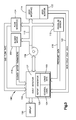
- FIG. 1 a functional block diagram illustrating one embodiment of a breathing gas delivery system 10 is shown.
- the system 10 has a controller 12, a display 13, an air flow source 14, one or more control parameter sensors 16, and a user interface 18 through which the breathing gas is supplied to the user.
- the controller 12 includes control logic 24, storage means for storing usage data 25, and is configured to that manipulate the usage data to generate feedback for communication to the user via the a feedback communicator such as a display 13.
- the air flow source 14 includes a blower 42 that provides a variable flow of air through an outlet 44 that is in fluid communication with the user interface. Breathable gas flows from the blower outlet 44 to a user interface 18.
- the user interface 18 can be any nasal mask, face mask, cannula, or similar device.
- the controller 12 is preferably processor-based and can include various input/output circuitry including analog-to-digital (A/D) inputs and digital-to-analog (D/A) outputs.
- A/D analog-to-digital
- D/A digital-to-analog
- the controller 12 controls the air flow source 14 based on the value of the control parameter sensed by the sensor(s) 16.
- the controller controls the air flow source by monitoring data from the control parameter sensors.
- the controller may also control the air flow source based on data obtained from the user interface 16 and operating parameters of the air flow source itself.
- Usage data 25 is collected during operation of the system.
- the usage data may include a subset of data that is used in open or closed loop control of the air flow source as well as data that is collected for the purpose of providing usage feedback.
- the report generator 26 stores one or more therapeutic targets for a given user and compares the usage data with the therapeutic target to provide qualitative feedback to a user. For example, if a user has been given a target usage time of six hours per night, the report generator will compare the actual usage time with the target of six hours and provide feedback that communicates the results of the comparison. In this manner the feedback is qualitative because it provides more than just the raw usage time data, and informs a user how therapy is progressing compared to their specific therapeutic target.
- Figures 2 and 3 are functional block diagrams that include more detail about various components of a system for providing a breathing gas 100 (Figure 2) and 100' ( Figure 3).
- the one or more control parameter sensors 16 (Figure 1) can include a variety of sensors, some of which are shown in Figures 2 and 3. Any or all of the sensors shown in Figures 2 and 3 may be included in the system and additional sensors may also be appropriately used in practice of the invention.
- a pressure sensor 112 senses the pressure in the flow path between a blower 106 and the user interface 114. This pressure is associated with and indicative of the pressure in the user interface 114.
- a flow sensor 124 senses a flow rate of breathing gas through the flow path. Data from either or both of the pressure sensor 112 and flow sensor 124 can be used to deduce usage data, such as a level of obstruction present in the user's respiratory tract or a quality of fit between the user interface 114 and the user.
- One or more user monitors 122 may be employed to collect usage data by directly sensing various physical parameters of the user.
- the user monitor may include a heart rate monitor and/or a pulse-oximeter.
- the user monitors may be in wireless communication with the controller 102 to improve user comfort.
- the air flow source 14 may be controlled using any number of techniques.
- the air flow source may include a variable position poppet valve 108 controlled by a bi-directional stepper motor 109.
- the stepper motor moves the poppet valve within the air flow path to route a portion of the air through the outlet and re-circulate the remainder of the air to the blower.
- the controller 102 controls the stepper motor 109 to position the poppet valve 108 according to the pressure sensed by pressure sensor 112 and/or the gas flow sensed by the gas flow sensor 124.
- data regarding the valve position and stepper motor parameters is monitored as part of closed loop control.
- the air flow can be varied by directly controlling a blower motor 208, such as, for example, by pulse width modulation of the blower motor's control signal.
- the controller 102 controls the blower motor 208 according to the pressure sensed by pressure sensor 112 and/or the gas flow sensed by the gas flow sensor 124. Data regarding the blower motor's operation is monitored by the controller 102 as part of closed loop control of the blower motor.
- a system that utilizes this type of air flow source is described in U.S. Patent No. 6,990,980 , which is incorporated herein by reference in its entirety.
- the controller 102 may include an event detector 127 that evaluates any or all of the inputs to the controller shown in Figures 2 and 3.
- the event detector includes logic that detects occurrences of apnea, hypopnea, abnormal breathing rates or cycles, or any number of respiratory events related to breathing gas therapy delivered by the system.
- the event detector logs occurrences of the various respiratory events and the information logged by the event detector is accessible to the report generator 126.
- the report generator inputs usage data or deduces usage data from any or all of the sensors shown in Figures 2 and 3 as well as the event detector 127 if present.
- usage data can be obtained or deduced from the user interface, user monitor, flow sensor, pressure sensor, sensed valve position, sensed stepper motor operating parameters, and sensed blower motor operating parameters.
- the report generator is capable of storing one or more therapeutic targets, such as a duration of use per night, a maximum number of abnormal breathing events, or any number of other targets.
- the report generator may also be capable of extrapolating information to be presented as feedback from usage data.
- the report generator may deduce a usage time or mask fit quality from flow or pressure data.
- the report generator 126 compares usage data to the corresponding therapeutic target and presents the results of this comparison to the user on the display 120.
- the rectangular elements denote processing blocks and represent software instructions or groups of instructions.
- the flow diagrams shown and described herein do not depict syntax of any particular programming language. Rather, the flow diagrams illustrate the functional information one skilled in the art may use to fabricate circuits or to generate software to perform the processing of the system. It should be noted that many routine program elements, such as initialization of loops and variables and the use of temporary variables are not shown.
- FIG. 4 is a flowchart illustrating a method 200 that provides feedback to a user of a system for providing a breathing gas.
- usage data is input to the report generator.
- the usage data can be obtained, for example, from monitors on the patient, sensors in the system, or control parameters of the air flow source.
- the usage data is compared to a therapeutic target for the user.
- the therapeutic target may be input by a therapist or doctor and may be based on baseline information gathered from the user prior to the start of therapy such as, for example, a typical number of respiratory events experienced per night or an average blood oxygen level during sleep.
- usage data may need to be combined or manipulated to be compared to the target.
- a feedback value that represents the results of the comparison between the usage data and the therapeutic target is generated.
- the feedback may be, for example, an indication as to whether a particular characteristic of usage falls within an acceptable range.
- the feedback value may be, for example, a scaled version of the usage data when compared to the therapeutic target.
- the feedback value may be, for example, a difference between usage data during a given period of use and baseline data collected from the patient prior to therapy.
- the feedback value is provided. In the described embodiments, the feedback value is displayed on an alphanumeric display or in the form of one or more colored lights.
- any method of communicating the feedback value to the user including, for example, audible signals or removable memory media that can be accessed by a user's computer to provide the feedback can be used in practice of the present invention.
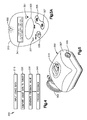
- the display 120 may be a part of a CPAP unit 300 shown in Figures 5 and 5A.
- the CPAP unit includes a power source 302, a housing 307 that contains the blower, a gas outlet 305 through which the therapeutic gas exits the unit, and an operating interface panel 310.
- the operating interface panel includes a power button 321, heater button 335, increment/decrement button 325/327, and an "ENTER" button 323.
- the panel 310 includes an alphanumeric display 341 that can display messages that present feedback values and may also include an illuminated light 355 that shows the color red or green depending on whether the feedback falls within a range of acceptable values or outside the range of acceptable values.
- the breathing gas delivery system usage time may be monitored. This usage time can be monitored, for example, by recording a start and stop time.
- the usage time data can be converted to feedback by comparing the usage time to a stored target usage time and calculating a relative usage time, such as 90% of the target usage time was achieved for a given night's usage.
- This relative usage time data can be recorded over a predetermined interval, such as weekly.
- a running average of relative usage for the interval and/or the relative usage for the previous night can be communicated to the user on a display or using another feedback communication mechanism as will be discussed below.
- pressure and/or gas flow may be monitored over the course of one or more usage periods. Pressure and/or flow levels are recorded and used to generate feedback corresponding to an appropriate pressure setting for use with a PAP device that has a single pressure setting that is manually entered. This can allow a user to switch to a more inexpensive PAP device once a pressure level setting has been determined for them.
- a combination of the pressure data and the valve position data can be used to generate feedback related to a leak condition. For example, with the mask properly installed, an initial baseline pressure and/or gas flow and valve position can be recorded over a short time duration while the user is awake and it can be verified that the mask is properly installed. In subsequent usages, the pressure and valve position when the user initially places the mask on his face can be compared to the baseline pressure/flow/position data. If the pressure/flow/position varies from the baseline data, the user may be alerted to adjust the mask or to check for a leak in the system.
- Apnea events can be detected and recorded by monitoring valve position or gas flow. A lack of valve movement or a drop in gas flow over a period of time indicates that the user has stopped breathing. Valve movement and/or gas flow data can thus be converted to feedback corresponding to a total number of apnea events that occurs over a given period of time. A number of apnea events may also be presented as indexed over predetermined intervals, such as an average number of events per hour. Additional information such as the duration of apnea events or a comparison with data concerning apnea events experienced by the user in the past may also be communicated to the user. In addition, instructions to the user may be stored in memory that are correlated to a given quantity of apnea events. Instructions corresponding to a detected quantity of apnea events can be retrieved from memory and displayed to a user.
- the position of the valve and/or gas flow rate may also be used to detect hypopnea, or under-breathing, events in which insufficient air is taken in during inspiration.
- the valve position or gas flow rate may indicate that inspiration is of insufficient duration or pressure.
- a total number of hypopnea events and/or a comparison with data concerning apnea events experienced by the user in the past can be provided.
- a number of hypopnea events may also be presented as indexed over predetermined intervals, such as an average number of events per hour.
- instructions to the user may be stored in memory that are correlated to a given quantity of hypopnea events. Instructions corresponding to a detected quantity of hypopnea events can be retrieved from memory and displayed to a user.
- Usage data can be in the form of user physical parameters, such as, for example, blood oxygen saturation level and heart rate can be monitored using a pulse-oximeter. Signals from the pulse-oximeter can be used to generate feedback relating to an overall quality of respiration as well as pinpointing stress events that occurred during usage. An average, high, or low oxygen or heart rate level can be determined as well as an indexed value that gives an average over a given interval of time. Any of these values as well as an indication of the overall quality or number of occurrences of stress events can be communicated to the user.
- instructions to the user may be stored in memory that are correlated to a given range of oxygen saturation level or heart rate. Instructions corresponding to a detected level can be retrieved from memory and displayed to a user.
- Feedback indicator mechanisms can include visual displays, printouts, or transmission of the feedback indicator by another method.
- the pressurized breathing gas respiratory therapy device may include a display that displays an alphanumeric message.
- Alphanumeric messages may include, for example, an indication of relative time usage with respect to a given target, an appropriate pressure setting for the device, an indication as to whether a leak exists in the system, a number of apnea or hypopnea events, or an oxygen saturation level or heart rate.
- the alphanumeric display may also display stored instructions that correspond to actions that should be taken by the user based on the observed usage data.
- the instructions may instruct the user to check that the mask is properly fitted to the face or to see a sleep specialist, or communicate an overall quality of sleep that has been attained based on any or all of the above outlined usage data.
- a numeric display may display a number that is correlated to a feedback indicator.
- a user may be given an index that correlates the display numbers with feedback messages.
- Icons may be displayed that symbolize the various feedback indicators. Colored lights, such as red, yellow, and green, or chimes or buzzers, can be activated to indicate whether usage data fell within an acceptable, marginally acceptable, or unacceptable range.
- a printout may be provided for the user to take to their sleep specialist.
- the feedback indicator may be transmitted to a separate storage device such as a memory card or to a communication device such as a PDA, cell phone, or computer.
Abstract
Description
- This application claims the benefit of priority from
U.S. Provisional Patent Application Serial Nos. 60/845,392, filed on September 18, 2006 60/891,772, filed on February 27, 2007 - Obstructive sleep apnea is an airway breathing disorder caused by relaxation of the muscles of the upper airway to the point where the upper airway collapses or becomes obstructed by the soft tissue supported by these same muscles. It is known that obstructive sleep apnea can be treated through the application of pressurized air to the nasal passages of a user. The application of pressurized air forms a pneumatic splint in the upper airway of the user thereby preventing the collapse or obstruction thereof. Devices that provide the pressurized breathing gas are known as positive airway pressure, or PAP, devices.
- A method for providing feedback to a user of a breathing gas delivery system includes collecting usage data during use of the breathing gas delivery system, comparing the usage data to a therapeutic target, generating feedback based on the comparison of the usage data to the therapeutic target; and communicating the feedback to the user. An apparatus for providing feedback includes a user interface in communication with the air flow source and configured to be coupled to a user to provide air from the air flow source to the user, a controller having memory for storing a therapeutic target, one or more usage data inputs. The controller is configured to compare usage data to the therapeutic target to determine feedback for the user. A feedback communicator presents the feedback to the user.
- In the accompanying drawings which are incorporated in and constitute a part of the specification, embodiments of the invention are illustrated, which, together with a general description of the invention given above, and the detailed description given below, serve to example the principles of this invention.
- Figure 1 a functional block diagram illustrating a breathing gas delivery system that provides user feedback.
- Figure 2 is a functional block diagram illustrating a breathing gas delivery system that provides user feedback.
- Figure 3 a functional block diagram illustrating a breathing gas delivery system that provides user feedback.
- Figure 4 is a flowchart illustrating one example procedure for operation of the breathing gas delivery system.
- Figure 5 is a perspective view of a CPAP device that is capable of providing user feedback according to an embodiment of the present invention.
- Figure 5A is close up view of a display of the CPAP device of Figure 5.
- Prior to discussing the various embodiments, a review of the definitions of some exemplary terms used throughout the disclosure is appropriate. Both singular and plural forms of all terms fall within each meaning:
- Pressurized Breathing Gas Respiratory Therapy Device, as used herein, includes, but is not limited to, all Positive Air Pressure (PAP) devices including Continuous PAP (CPAP), auto-adjust PAP, and bi-level devices, Proportional Positive Air Pressure (PPAP) devices, a ventilator device, a gas therapy device, an oxygen therapy device, or any device that is used to provide one or more than one pressure with any form of pressure variability to treat either obstructive or central apnea, or both (mixed or complex apnea).
- "Logic," as used herein, includes but is not limited to hardware, firmware, software and/or combinations of each to perform a function(s) or an action(s), and/or to cause a function or action from another component. For example, based on a desired application or needs, logic may include a software controlled microprocessor, discrete logic such as an application specific integrated circuit (ASIC), or other programmed logic device. Logic may also be fully embodied as software.
- "Software," as used herein, includes but is not limited to one or more computer readable and/or executable instructions that cause a computer or other electronic device to perform functions, actions, and/or behave in a desire manner. The instructions may be embodied in various forms such as routines, algorithms, modules or programs including separate applications or code from dynamically linked libraries. Software may also be implemented in various forms such as a stand-alone program, a function call, a servlet, an applet, instructions stored in a memory, part of an operating system or other type of executable instructions. It will be appreciated by one of ordinary skill in the art that the form of software is dependent on, for example, requirements of a desired application, the environment it runs on, and/or the desires of a designer/programmer or the like.
- The systems and methods described herein are particularly suited for assisting the respiration of spontaneously breathing users, though they may also be applied to other respiratory regimens including, for example, central sleep apnea, mixed (complex) apnea, and acute and homecare ventilation. Referring now to Figure 1, a functional block diagram illustrating one embodiment of a breathing
gas delivery system 10 is shown. Thesystem 10 has acontroller 12, adisplay 13, anair flow source 14, one or morecontrol parameter sensors 16, and auser interface 18 through which the breathing gas is supplied to the user. Thecontroller 12 includescontrol logic 24, storage means for storingusage data 25, and is configured to that manipulate the usage data to generate feedback for communication to the user via the a feedback communicator such as adisplay 13. The generation of feedback is performed in the described embodiment using areport generator 26. Theair flow source 14 includes ablower 42 that provides a variable flow of air through anoutlet 44 that is in fluid communication with the user interface. Breathable gas flows from theblower outlet 44 to auser interface 18. Theuser interface 18 can be any nasal mask, face mask, cannula, or similar device. Thecontroller 12 is preferably processor-based and can include various input/output circuitry including analog-to-digital (A/D) inputs and digital-to-analog (D/A) outputs. According to thecontrol logic 24, that may be implemented in software, thecontroller 12 controls theair flow source 14 based on the value of the control parameter sensed by the sensor(s) 16. The controller controls the air flow source by monitoring data from the control parameter sensors. The controller may also control the air flow source based on data obtained from theuser interface 16 and operating parameters of the air flow source itself. -
Usage data 25 is collected during operation of the system. The usage data may include a subset of data that is used in open or closed loop control of the air flow source as well as data that is collected for the purpose of providing usage feedback. Thereport generator 26 stores one or more therapeutic targets for a given user and compares the usage data with the therapeutic target to provide qualitative feedback to a user. For example, if a user has been given a target usage time of six hours per night, the report generator will compare the actual usage time with the target of six hours and provide feedback that communicates the results of the comparison. In this manner the feedback is qualitative because it provides more than just the raw usage time data, and informs a user how therapy is progressing compared to their specific therapeutic target. - Figures 2 and 3 are functional block diagrams that include more detail about various components of a system for providing a breathing gas 100 (Figure 2) and 100' (Figure 3). The one or more control parameter sensors 16 (Figure 1) can include a variety of sensors, some of which are shown in Figures 2 and 3. Any or all of the sensors shown in Figures 2 and 3 may be included in the system and additional sensors may also be appropriately used in practice of the invention. For example, a
pressure sensor 112 senses the pressure in the flow path between ablower 106 and theuser interface 114. This pressure is associated with and indicative of the pressure in theuser interface 114. Aflow sensor 124 senses a flow rate of breathing gas through the flow path. Data from either or both of thepressure sensor 112 andflow sensor 124 can be used to deduce usage data, such as a level of obstruction present in the user's respiratory tract or a quality of fit between theuser interface 114 and the user. - One or
more user monitors 122 may be employed to collect usage data by directly sensing various physical parameters of the user. For example, the user monitor may include a heart rate monitor and/or a pulse-oximeter. The user monitors may be in wireless communication with thecontroller 102 to improve user comfort. - The air flow source 14 (Figure 1) may be controlled using any number of techniques. For example, as shown schematically in Figure 2, the air flow source may include a variable
position poppet valve 108 controlled by abi-directional stepper motor 109. To vary the amount of air flow that flows through the outlet to the user, the stepper motor moves the poppet valve within the air flow path to route a portion of the air through the outlet and re-circulate the remainder of the air to the blower. Thecontroller 102 controls thestepper motor 109 to position thepoppet valve 108 according to the pressure sensed bypressure sensor 112 and/or the gas flow sensed by thegas flow sensor 124. In addition, data regarding the valve position and stepper motor parameters is monitored as part of closed loop control. An example of such a system is described in more detail inU.S. Patent No. 7,152,598 , andU.S. Patent Application Serial No. 11/157,089, filed June 20, 2005 - Alternatively, as shown schematically in Figure 3, the air flow can be varied by directly controlling a
blower motor 208, such as, for example, by pulse width modulation of the blower motor's control signal. Thecontroller 102 controls theblower motor 208 according to the pressure sensed bypressure sensor 112 and/or the gas flow sensed by thegas flow sensor 124. Data regarding the blower motor's operation is monitored by thecontroller 102 as part of closed loop control of the blower motor. A system that utilizes this type of air flow source is described inU.S. Patent No. 6,990,980 , which is incorporated herein by reference in its entirety. - The
controller 102 may include anevent detector 127 that evaluates any or all of the inputs to the controller shown in Figures 2 and 3. The event detector includes logic that detects occurrences of apnea, hypopnea, abnormal breathing rates or cycles, or any number of respiratory events related to breathing gas therapy delivered by the system. The event detector logs occurrences of the various respiratory events and the information logged by the event detector is accessible to thereport generator 126. - To provide feedback to the user, the report generator inputs usage data or deduces usage data from any or all of the sensors shown in Figures 2 and 3 as well as the
event detector 127 if present. For example, usage data can be obtained or deduced from the user interface, user monitor, flow sensor, pressure sensor, sensed valve position, sensed stepper motor operating parameters, and sensed blower motor operating parameters. The report generator is capable of storing one or more therapeutic targets, such as a duration of use per night, a maximum number of abnormal breathing events, or any number of other targets. The report generator may also be capable of extrapolating information to be presented as feedback from usage data. For example, the report generator may deduce a usage time or mask fit quality from flow or pressure data. Thereport generator 126 compares usage data to the corresponding therapeutic target and presents the results of this comparison to the user on thedisplay 120. - Referring now to Figure 4, the operation of the system for providing user feedback will be described with reference to the flowchart illustrated therein. In the flowchart, the rectangular elements denote processing blocks and represent software instructions or groups of instructions. The flow diagrams shown and described herein do not depict syntax of any particular programming language. Rather, the flow diagrams illustrate the functional information one skilled in the art may use to fabricate circuits or to generate software to perform the processing of the system. It should be noted that many routine program elements, such as initialization of loops and variables and the use of temporary variables are not shown.
- Figure 4 is a flowchart illustrating a
method 200 that provides feedback to a user of a system for providing a breathing gas. At 210, usage data is input to the report generator. As discussed above, the usage data can be obtained, for example, from monitors on the patient, sensors in the system, or control parameters of the air flow source. At 220 the usage data is compared to a therapeutic target for the user. The therapeutic target may be input by a therapist or doctor and may be based on baseline information gathered from the user prior to the start of therapy such as, for example, a typical number of respiratory events experienced per night or an average blood oxygen level during sleep. As discussed above, usage data may need to be combined or manipulated to be compared to the target. At 230, a feedback value that represents the results of the comparison between the usage data and the therapeutic target is generated. The feedback may be, for example, an indication as to whether a particular characteristic of usage falls within an acceptable range. The feedback value may be, for example, a scaled version of the usage data when compared to the therapeutic target. The feedback value may be, for example, a difference between usage data during a given period of use and baseline data collected from the patient prior to therapy. At 240, the feedback value is provided. In the described embodiments, the feedback value is displayed on an alphanumeric display or in the form of one or more colored lights. However, any method of communicating the feedback value to the user, including, for example, audible signals or removable memory media that can be accessed by a user's computer to provide the feedback can be used in practice of the present invention. - The
display 120 may be a part of aCPAP unit 300 shown in Figures 5 and 5A. The CPAP unit includes apower source 302, ahousing 307 that contains the blower, agas outlet 305 through which the therapeutic gas exits the unit, and anoperating interface panel 310. The operating interface panel includes apower button 321,heater button 335, increment/decrement button 325/327, and an "ENTER"button 323. Thepanel 310 includes analphanumeric display 341 that can display messages that present feedback values and may also include anilluminated light 355 that shows the color red or green depending on whether the feedback falls within a range of acceptable values or outside the range of acceptable values. - The following examples are intended to further describe the breathing gas delivery system with feedback. The scope of embodiments that can be used to practice the breathing gas delivery system with feedback is not limited to the examples. In one embodiment the breathing gas delivery system usage time may be monitored. This usage time can be monitored, for example, by recording a start and stop time. The usage time data can be converted to feedback by comparing the usage time to a stored target usage time and calculating a relative usage time, such as 90% of the target usage time was achieved for a given night's usage. This relative usage time data can be recorded over a predetermined interval, such as weekly. A running average of relative usage for the interval and/or the relative usage for the previous night can be communicated to the user on a display or using another feedback communication mechanism as will be discussed below.
- In an auto-adjusting PAP device, pressure and/or gas flow may be monitored over the course of one or more usage periods. Pressure and/or flow levels are recorded and used to generate feedback corresponding to an appropriate pressure setting for use with a PAP device that has a single pressure setting that is manually entered. This can allow a user to switch to a more inexpensive PAP device once a pressure level setting has been determined for them.
- By monitoring pressure and/or gas flow and valve position, a combination of the pressure data and the valve position data can be used to generate feedback related to a leak condition. For example, with the mask properly installed, an initial baseline pressure and/or gas flow and valve position can be recorded over a short time duration while the user is awake and it can be verified that the mask is properly installed. In subsequent usages, the pressure and valve position when the user initially places the mask on his face can be compared to the baseline pressure/flow/position data. If the pressure/flow/position varies from the baseline data, the user may be alerted to adjust the mask or to check for a leak in the system.
- Apnea events can be detected and recorded by monitoring valve position or gas flow. A lack of valve movement or a drop in gas flow over a period of time indicates that the user has stopped breathing. Valve movement and/or gas flow data can thus be converted to feedback corresponding to a total number of apnea events that occurs over a given period of time. A number of apnea events may also be presented as indexed over predetermined intervals, such as an average number of events per hour. Additional information such as the duration of apnea events or a comparison with data concerning apnea events experienced by the user in the past may also be communicated to the user. In addition, instructions to the user may be stored in memory that are correlated to a given quantity of apnea events. Instructions corresponding to a detected quantity of apnea events can be retrieved from memory and displayed to a user.
- The position of the valve and/or gas flow rate may also be used to detect hypopnea, or under-breathing, events in which insufficient air is taken in during inspiration. The valve position or gas flow rate may indicate that inspiration is of insufficient duration or pressure. As with apnea events, a total number of hypopnea events and/or a comparison with data concerning apnea events experienced by the user in the past can be provided. A number of hypopnea events may also be presented as indexed over predetermined intervals, such as an average number of events per hour. In addition, instructions to the user may be stored in memory that are correlated to a given quantity of hypopnea events. Instructions corresponding to a detected quantity of hypopnea events can be retrieved from memory and displayed to a user.
- Usage data can be in the form of user physical parameters, such as, for example, blood oxygen saturation level and heart rate can be monitored using a pulse-oximeter. Signals from the pulse-oximeter can be used to generate feedback relating to an overall quality of respiration as well as pinpointing stress events that occurred during usage. An average, high, or low oxygen or heart rate level can be determined as well as an indexed value that gives an average over a given interval of time. Any of these values as well as an indication of the overall quality or number of occurrences of stress events can be communicated to the user. In addition, instructions to the user may be stored in memory that are correlated to a given range of oxygen saturation level or heart rate. Instructions corresponding to a detected level can be retrieved from memory and displayed to a user.
- Feedback indicator mechanisms can include visual displays, printouts, or transmission of the feedback indicator by another method. The pressurized breathing gas respiratory therapy device may include a display that displays an alphanumeric message. Alphanumeric messages may include, for example, an indication of relative time usage with respect to a given target, an appropriate pressure setting for the device, an indication as to whether a leak exists in the system, a number of apnea or hypopnea events, or an oxygen saturation level or heart rate. The alphanumeric display may also display stored instructions that correspond to actions that should be taken by the user based on the observed usage data. For example, the instructions may instruct the user to check that the mask is properly fitted to the face or to see a sleep specialist, or communicate an overall quality of sleep that has been attained based on any or all of the above outlined usage data. A numeric display may display a number that is correlated to a feedback indicator. A user may be given an index that correlates the display numbers with feedback messages. Icons may be displayed that symbolize the various feedback indicators. Colored lights, such as red, yellow, and green, or chimes or buzzers, can be activated to indicate whether usage data fell within an acceptable, marginally acceptable, or unacceptable range. A printout may be provided for the user to take to their sleep specialist. The feedback indicator may be transmitted to a separate storage device such as a memory card or to a communication device such as a PDA, cell phone, or computer.
- While the present invention has been illustrated by the description of embodiments thereof, and while the embodiments have been described in considerable detail, it is not the intention of this specification to restrict or in any way limit the scope of the appended claims to such detail. Additional advantages and modifications will readily appear to those skilled in the art. Therefore, the invention, in its broader aspects, is not limited to the specific details, the representative apparatus, and illustrative examples shown and described. Accordingly, departures may be made from such details without departing from the spirit or scope of the applicant's general inventive concept.
Claims (19)
- A method of providing feedback to a user of a breathing gas delivery system, the method comprising the steps of:collecting usage data during use of the breathing gas delivery system;comparing the usage data to a therapeutic target;generating feedback based on the comparison of the usage data to the therapeutic target; andcommunicating the feedback to the user.
- The method of claim 1 comprising the step of manipulating the usage data and comparing the manipulated usage data to the therapeutic target.
- The method of claim 2 wherein the step of manipulating the usage data is performed by comparing the usage data to predefined respiratory event criteria and determining that a respiratory event has occurred based on the comparison of the usage data to the event criteria.
- The method of any one of claims 1 to 3 comprising the step of storing a therapeutic target for the user.
- The method of claim 4 wherein the step of storing a therapeutic target for a user is performed by storing a target based on baseline data collected from the user.
- The method of any one of claims 1 to 5 wherein the step of collecting usage data comprises recording a breathing gas delivery system activation and deactivation time.
- The method of any one of claims 1 to 6 wherein the step of collecting usage data comprises recording a gas pressure in the breathing gas delivery system.
- The method ofany one of claims 1 to 7 wherein the step of collecting usage data comprises recording a flow rate of gas through the breathing gas delivery system.
- The method of any one of claims 1 to 8 wherein the step of collecting usage data comprises recording a physical parameter of a user.
- The method of any one of claims 1 to 9 wherein the step of collecting usage data comprises recording an operating parameter of a breathing gas delivery system component.
- The method of any one of claims 1 to 10 wherein the step of communicating the feedback to the user is performed by illuminating a light.
- The method of any one of claims 1 to 10 wherein the step of communicating the feedback to the user is performed by displaying an alphanumeric message on the breathing gas deliver system.
- A breathing gas delivery system comprising:a user interface in communication with an air flow source and configured to be coupled to a user to provide air from the air flow source to the user;a controller comprising:memory for storing a therapeutic target;one or more usage data inputs;the controller configured to compare usage data to the therapeutic target to determine feedback for the user; anda feedback communicator that presents the feedback determined by the controller to the user.
- The breathing gas delivery system of claim 13 wherein the feedback communicator comprises an alphanumeric display.
- The breathing gas delivery system of claim 13 or 14 wherein the feedback communicator comprises one or more lights.
- The breathing gas delivery system of any one of claims 13 to 15 wherein at least one usage data input is in signal communication with a pressure sensor disposed in an air flow path along which the air provided to the user flows.
- The breathing gas delivery system of any one of claims 13 to 16 wherein at least one usage data input is in signal communication with a flow sensor disposed in an air flow path along which the air provided to the user flows.
- The breathing gas delivery system of any one of claims 13 to 17 comprising at least one user monitor that monitors a physical parameter of the user.
- The breathing gas delivery system of any one of claims 13 to 18 comprising an event detector that logs an occurrence of breathing events based on usage data.
Applications Claiming Priority (2)
| Application Number | Priority Date | Filing Date | Title |
|---|---|---|---|
| US84539206P | 2006-09-18 | 2006-09-18 | |
| US89177207P | 2007-02-27 | 2007-02-27 |
Publications (1)
| Publication Number | Publication Date |
|---|---|
| EP1900387A1 true EP1900387A1 (en) | 2008-03-19 |
Family
ID=38866712
Family Applications (1)
| Application Number | Title | Priority Date | Filing Date |
|---|---|---|---|
| EP07116619A Withdrawn EP1900387A1 (en) | 2006-09-18 | 2007-09-18 | Breathing gas delivery system with user feedback |
Country Status (3)
| Country | Link |
|---|---|
| US (1) | US20080078384A1 (en) |
| EP (1) | EP1900387A1 (en) |
| CA (1) | CA2602620A1 (en) |
Cited By (6)
| Publication number | Priority date | Publication date | Assignee | Title |
|---|---|---|---|---|
| WO2010116275A1 (en) | 2009-04-08 | 2010-10-14 | Koninklijke Philips Electronics N.V. | System and method for providing feedback to a subject regarding reception of positive airway support therapy |
| WO2012085756A1 (en) * | 2010-12-20 | 2012-06-28 | Koninklijke Philips Electronics N.V. | System and method of providing feedback to a subject receiving respiratory therapy via a client device associated with the subject |
| WO2014202924A1 (en) * | 2013-06-18 | 2014-12-24 | Smiths Medical International Limited | Respiratory therapy apparatus and methods |
| EP3149696A4 (en) * | 2014-05-27 | 2018-05-16 | ResMed Limited | Remote data management for medical devices |
| EP3539600A1 (en) * | 2013-12-17 | 2019-09-18 | ResMed Pty Ltd | A respiratory pressure treatment system |
| US10814083B2 (en) | 2015-07-07 | 2020-10-27 | ResMed Pty Ltd | Respiratory pressure therapy device |
Families Citing this family (13)
| Publication number | Priority date | Publication date | Assignee | Title |
|---|---|---|---|---|
| US8617068B2 (en) * | 2006-09-27 | 2013-12-31 | ResMed Limitied | Method and apparatus for assessing sleep quality |
| US9149589B2 (en) | 2009-02-23 | 2015-10-06 | Trudell Medical International | Method and device for performing orientation dependent oscillating positive expiratory pressure therapy |
| US8485179B1 (en) | 2009-02-23 | 2013-07-16 | Trudell Medical International | Oscillating positive expiratory pressure device |
| US8378832B2 (en) | 2009-07-09 | 2013-02-19 | Harry J. Cassidy | Breathing disorder treatment system and method |
| US8736122B2 (en) * | 2009-09-24 | 2014-05-27 | Siemens Industry, Inc. | Induction motor ventilated heat shield for bearings |
| US10857319B2 (en) | 2011-01-14 | 2020-12-08 | Koninklijke Philips N.V. | Measuring continuity of therapy associated with a respiratory treatment device |
| AU2012264277B2 (en) * | 2011-06-03 | 2016-12-22 | Koninklijke Philips N.V. | Pressure adjustment in a respiratory therapy device |
| JP6207599B2 (en) * | 2012-06-08 | 2017-10-04 | コーニンクレッカ フィリップス エヌ ヴェKoninklijke Philips N.V. | Patient sleep therapy self-management tool |
| US9872965B2 (en) * | 2012-06-15 | 2018-01-23 | Breathe Technologies, Inc. | Method and system for operating a patient ventilation device |
| WO2016178114A1 (en) * | 2015-05-07 | 2016-11-10 | Koninklijke Philips N.V. | Monitoring the degradation of a component of a patient interface device |
| US11420007B2 (en) | 2020-08-05 | 2022-08-23 | Effortless Oxygen, Llc | Flow triggered gas delivery |
| US11247008B1 (en) | 2020-08-05 | 2022-02-15 | Effortless Oxygen, Llc | Flow triggered gas delivery |
| US11318276B2 (en) | 2020-08-05 | 2022-05-03 | Effortless Oxygen, Llc | Flow triggered gas delivery |
Citations (6)
| Publication number | Priority date | Publication date | Assignee | Title |
|---|---|---|---|---|
| WO1994013349A1 (en) * | 1992-12-09 | 1994-06-23 | Puritan Bennett Corporation | Compliance meter for respiratory therapy |
| US6273088B1 (en) | 1997-06-13 | 2001-08-14 | Sierra Biotechnology Company Lc | Ventilator biofeedback for weaning and assistance |
| WO2002058619A2 (en) * | 2001-01-22 | 2002-08-01 | Cardiopulmonary Corporation | Ventilator control system and method |
| US6990980B2 (en) | 2000-09-28 | 2006-01-31 | Invacare Corporation | Carbon dioxide-based Bi-level CPAP control |
| WO2006056444A1 (en) | 2004-11-24 | 2006-06-01 | Map Medizin-Technologie Gmbh | Monitor for cpap/ventilator apparatus |
| US7152598B2 (en) | 2003-06-23 | 2006-12-26 | Invacare Corporation | System and method for providing a breathing gas |
Family Cites Families (5)
| Publication number | Priority date | Publication date | Assignee | Title |
|---|---|---|---|---|
| US7024235B2 (en) * | 2002-06-20 | 2006-04-04 | University Of Florida Research Foundation, Inc. | Specially configured nasal pulse oximeter/photoplethysmography probes, and combined nasal probe/cannula, selectively with sampler for capnography, and covering sleeves for same |
| ES2725486T3 (en) * | 2003-08-14 | 2019-09-24 | Teijin Pharma Ltd | Oxygen concentration apparatus |
| US7591265B2 (en) * | 2003-09-18 | 2009-09-22 | Cardiac Pacemakers, Inc. | Coordinated use of respiratory and cardiac therapies for sleep disordered breathing |
| US7469697B2 (en) * | 2003-09-18 | 2008-12-30 | Cardiac Pacemakers, Inc. | Feedback system and method for sleep disordered breathing therapy |
| US7390304B2 (en) * | 2005-03-31 | 2008-06-24 | Medical Graphics Corporation | Respiratory exchange ratio sensor |
-
2007
- 2007-09-17 CA CA002602620A patent/CA2602620A1/en not_active Abandoned
- 2007-09-17 US US11/856,115 patent/US20080078384A1/en not_active Abandoned
- 2007-09-18 EP EP07116619A patent/EP1900387A1/en not_active Withdrawn
Patent Citations (6)
| Publication number | Priority date | Publication date | Assignee | Title |
|---|---|---|---|---|
| WO1994013349A1 (en) * | 1992-12-09 | 1994-06-23 | Puritan Bennett Corporation | Compliance meter for respiratory therapy |
| US6273088B1 (en) | 1997-06-13 | 2001-08-14 | Sierra Biotechnology Company Lc | Ventilator biofeedback for weaning and assistance |
| US6990980B2 (en) | 2000-09-28 | 2006-01-31 | Invacare Corporation | Carbon dioxide-based Bi-level CPAP control |
| WO2002058619A2 (en) * | 2001-01-22 | 2002-08-01 | Cardiopulmonary Corporation | Ventilator control system and method |
| US7152598B2 (en) | 2003-06-23 | 2006-12-26 | Invacare Corporation | System and method for providing a breathing gas |
| WO2006056444A1 (en) | 2004-11-24 | 2006-06-01 | Map Medizin-Technologie Gmbh | Monitor for cpap/ventilator apparatus |
Cited By (22)
| Publication number | Priority date | Publication date | Assignee | Title |
|---|---|---|---|---|
| CN102387745A (en) * | 2009-04-08 | 2012-03-21 | 皇家飞利浦电子股份有限公司 | System and method for providing feedback to a subject regarding reception of positive airway support therapy |
| JP2012523261A (en) * | 2009-04-08 | 2012-10-04 | コーニンクレッカ フィリップス エレクトロニクス エヌ ヴィ | System and method for providing feedback to a subject regarding acceptance of positive airway pressure support therapy |
| CN102387745B (en) * | 2009-04-08 | 2014-10-29 | 皇家飞利浦电子股份有限公司 | System and method for providing feedback to a subject regarding reception of positive airway support therapy |
| US8881727B2 (en) | 2009-04-08 | 2014-11-11 | Koninklijke Philips N.V. | System and method for providing feedback to a subject regarding reception of positive airway support therapy |
| AU2010233417B2 (en) * | 2009-04-08 | 2014-11-20 | Koninklijke Philips Electronics N.V. | System and method for providing feedback to a subject regarding reception of positive airway support therapy |
| WO2010116275A1 (en) | 2009-04-08 | 2010-10-14 | Koninklijke Philips Electronics N.V. | System and method for providing feedback to a subject regarding reception of positive airway support therapy |
| WO2012085756A1 (en) * | 2010-12-20 | 2012-06-28 | Koninklijke Philips Electronics N.V. | System and method of providing feedback to a subject receiving respiratory therapy via a client device associated with the subject |
| CN103370005A (en) * | 2010-12-20 | 2013-10-23 | 皇家飞利浦电子股份有限公司 | System and method of providing feedback to a subject receiving respiratory therapy via a client device associated with the subject |
| US9463294B2 (en) | 2010-12-20 | 2016-10-11 | Koninklijke Philips N.V. | System and method of providing feedback to a subject receiving respiratory therapy via a client device associated with the subject |
| US11000654B2 (en) | 2013-06-18 | 2021-05-11 | Smiths Medical International Limited | Respiratory therapy apparatus and methods |
| WO2014202924A1 (en) * | 2013-06-18 | 2014-12-24 | Smiths Medical International Limited | Respiratory therapy apparatus and methods |
| US11058845B2 (en) | 2013-12-17 | 2021-07-13 | ResMed Pty Ltd | Respiratory pressure treatment system |
| US10864343B2 (en) | 2013-12-17 | 2020-12-15 | ResMed Pty Ltd | Respiratory pressure treatment system |
| EP3539600A1 (en) * | 2013-12-17 | 2019-09-18 | ResMed Pty Ltd | A respiratory pressure treatment system |
| US11219735B1 (en) | 2013-12-17 | 2022-01-11 | ResMed Pty Ltd | Respiratory pressure treatment system |
| US11219736B1 (en) | 2013-12-17 | 2022-01-11 | ResMed Pty Ltd | Respiratory pressure treatment system |
| US11389615B2 (en) | 2013-12-17 | 2022-07-19 | ResMed Pty Ltd | Respiratory pressure treatment system |
| US11400251B2 (en) | 2013-12-17 | 2022-08-02 | ResMed Pty Ltd | Respiratory pressure treatment system |
| US11759595B2 (en) | 2013-12-17 | 2023-09-19 | ResMed Pty Ltd | Respiratory pressure treatment system |
| EP3149696A4 (en) * | 2014-05-27 | 2018-05-16 | ResMed Limited | Remote data management for medical devices |
| US10814083B2 (en) | 2015-07-07 | 2020-10-27 | ResMed Pty Ltd | Respiratory pressure therapy device |
| US11850360B2 (en) | 2015-07-07 | 2023-12-26 | ResMed Pty Ltd | Respiratory pressure therapy device |
Also Published As
| Publication number | Publication date |
|---|---|
| CA2602620A1 (en) | 2008-03-18 |
| US20080078384A1 (en) | 2008-04-03 |
Similar Documents
| Publication | Publication Date | Title |
|---|---|---|
| EP1900387A1 (en) | Breathing gas delivery system with user feedback | |
| US5237987A (en) | Human lung ventilator system | |
| US5603315A (en) | Multiple mode oxygen delivery system | |
| EP1986723B1 (en) | Hardware configuration for pressure driver | |
| CN102186524B (en) | Accessory connection and data synchronication in a ventilator | |
| EP3585465B1 (en) | Automatic peep selection for mechanical ventilation | |
| US7469698B1 (en) | Parameter optimization in sleep apnea treatment apparatus | |
| US8453645B2 (en) | Three-dimensional waveform display for a breathing assistance system | |
| US6467477B1 (en) | Breath-based control of a therapeutic treatment | |
| US6000396A (en) | Hybrid microprocessor controlled ventilator unit | |
| EP3656431B1 (en) | Systems for drive pressure spontaneous ventilation | |
| EP1355690B1 (en) | Ventilator control system | |
| CN102333557B (en) | The asynchronous detection of patient-ventilator | |
| CN102711887B (en) | Utilize the servo-ventilation from the pressure drop of baseline | |
| JP5779506B2 (en) | Pressure support system with mechanical breathing function | |
| US20140000606A1 (en) | Methods and systems for mimicking fluctuations in delivered flow and/or pressure during ventilation | |
| EP2833978B1 (en) | Mechanical ventilation mask fit status indication | |
| US20020088464A1 (en) | Pressure support system with a low leak alarm and method of using same | |
| JP6431033B2 (en) | Dual pressure sensor patient ventilator | |
| CN104379199B (en) | Initial pressure for respiratory therapy | |
| US20020056452A1 (en) | Determination of mask fitting pressure and correct mask fit | |
| CN103260682B (en) | Depend on the Respiration assistance of breathing rate | |
| CN103189088A (en) | Pressure line purging system for a mechanical ventilator | |
| US7798143B1 (en) | Respiratory treatment device with patient reporting | |
| US20210393902A1 (en) | One-touch ventilation mode |
Legal Events
| Date | Code | Title | Description |
|---|---|---|---|
| PUAI | Public reference made under article 153(3) epc to a published international application that has entered the european phase |
Free format text: ORIGINAL CODE: 0009012 |
|
| AK | Designated contracting states |
Kind code of ref document: A1 Designated state(s): AT BE BG CH CY CZ DE DK EE ES FI FR GB GR HU IE IS IT LI LT LU LV MC MT NL PL PT RO SE SI SK TR |
|
| AX | Request for extension of the european patent |
Extension state: AL BA HR MK YU |
|
| 17P | Request for examination filed |
Effective date: 20080919 |
|
| AKX | Designation fees paid |
Designated state(s): AT BE BG CH CY CZ DE DK EE ES FI FR GB GR HU IE IS IT LI LT LU LV MC MT NL PL PT RO SE SI SK TR |
|
| 17Q | First examination report despatched |
Effective date: 20081103 |
|
| REG | Reference to a national code |
Ref country code: HK Ref legal event code: DE Ref document number: 1116109 Country of ref document: HK |
|
| STAA | Information on the status of an ep patent application or granted ep patent |
Free format text: STATUS: THE APPLICATION IS DEEMED TO BE WITHDRAWN |
|
| 18D | Application deemed to be withdrawn |
Effective date: 20130411 |