EP1905732A1 - Method for automatic allocation of sensors - Google Patents
Method for automatic allocation of sensors Download PDFInfo
- Publication number
- EP1905732A1 EP1905732A1 EP06020079A EP06020079A EP1905732A1 EP 1905732 A1 EP1905732 A1 EP 1905732A1 EP 06020079 A EP06020079 A EP 06020079A EP 06020079 A EP06020079 A EP 06020079A EP 1905732 A1 EP1905732 A1 EP 1905732A1
- Authority
- EP
- European Patent Office
- Prior art keywords
- sensor
- sensors
- central computer
- area
- system area
- Prior art date
- Legal status (The legal status is an assumption and is not a legal conclusion. Google has not performed a legal analysis and makes no representation as to the accuracy of the status listed.)
- Granted
Links
Images

Classifications
-
- B—PERFORMING OPERATIONS; TRANSPORTING
- B67—OPENING, CLOSING OR CLEANING BOTTLES, JARS OR SIMILAR CONTAINERS; LIQUID HANDLING
- B67D—DISPENSING, DELIVERING OR TRANSFERRING LIQUIDS, NOT OTHERWISE PROVIDED FOR
- B67D7/00—Apparatus or devices for transferring liquids from bulk storage containers or reservoirs into vehicles or into portable containers, e.g. for retail sale purposes
- B67D7/06—Details or accessories
- B67D7/08—Arrangements of devices for controlling, indicating, metering or registering quantity or price of liquid transferred
-
- H—ELECTRICITY
- H04—ELECTRIC COMMUNICATION TECHNIQUE
- H04L—TRANSMISSION OF DIGITAL INFORMATION, e.g. TELEGRAPHIC COMMUNICATION
- H04L61/00—Network arrangements, protocols or services for addressing or naming
- H04L61/50—Address allocation
- H04L61/5084—Providing for device mobility
-
- H—ELECTRICITY
- H04—ELECTRIC COMMUNICATION TECHNIQUE
- H04L—TRANSMISSION OF DIGITAL INFORMATION, e.g. TELEGRAPHIC COMMUNICATION
- H04L67/00—Network arrangements or protocols for supporting network services or applications
- H04L67/01—Protocols
- H04L67/12—Protocols specially adapted for proprietary or special-purpose networking environments, e.g. medical networks, sensor networks, networks in vehicles or remote metering networks
Definitions
- the present invention relates to a method for the automatic assignment of sensors to a system area in a central computer monitored system with at least two system areas.
- An example of an application of the present invention is the use of a fuel dispensing system at a gas station.
- a fuel pump For example, in the area of a fuel pump, different types of fuel are to be dispensed, such as diesel, gasoline, etc.
- Each of the fuel types defines a system area.
- the system has a central computer. This determines, for example, which of the fuel types is currently being output, that is, which system area is currently in use.
- the central computer also evaluates the required sensors, which may be, for example, pressure sensors, temperature sensors and the like.
- the procedure is usually such that such a system is created.
- the sensors have type-related identifiers, i. h., they identify by their identification, which type of sensor it is. Otherwise, they first identify themselves with a general address.
- a sensor is simply looped through to a specific terminal pole of a board and the computer simply accesses this interface in order to be able to obtain and evaluate the desired sensor signal.
- each sensor must be identified, addressed and assigned to the system area by the central computer.
- the present invention has for its object to provide a method for automated assignment of sensors to system areas in a central computer controlled or central computer monitored system.
- the main advantage of the method according to the invention is that an automatic address assignment of sensors by the central computer, thus eliminating a manual addressing process and also the address assignment is not fixed.
- By monitoring the system by means of a central computer no replacement or retrofitting work requires highly qualified personnel, which significantly reduces the operating costs of such a system.
- the central computer detects the sensors present in the system and identifies them, for example, on the basis of the type-related identifier. Furthermore, the central computer detects which system area is currently in operation and changes in the system sensors resulting from this operation. Thereafter, based on the changes of the respective sensor, this sensor is automatically assigned to the system area in operation. The process is run when the central computer detects the sensors present in the system, compares this detection with stored addresses of the sensors and determines that there are sensors in the system to which no address is assigned.
- An advantageous embodiment of the invention provides that the assignment is stored.
- the allocation is present in the following applications of the overall system, so that a direct access to the stored data can be made, and no re-run of the method with respect to the assignments made necessary, as long as there is no change in the sensors.
- the sensor transmits a signal to the central computer, it recognizes the associated operating system area, and vice versa, and can carry out further data processing.
- the central computer to the identified and associated sensor to a unique address.
- an address list is created in the central computer, so that depending on the operation of a system area, the associated address of the associated sensor can be retrieved.
- the inventive method is applied in a system for goods / product output, wherein the different system areas are formed by different goods / products.
- a further advantageous embodiment of the invention provides that the method is used in a system for dispensing fuels, wherein the different system areas are identified by the different fuels.
- temperature sensors are used as sensors.
- these may detect temperature changes on output, allowing the central computer to map the sensor to the appropriate type of fuel dispensed by a system area.
- a further advantageous embodiment of the invention provides that the method is carried out when commissioning a system and after each sensor change. As a result, a new address list is created each time, which takes into account the changes in the overall system. In addition, no highly skilled personnel is necessary, which manually inputs the changes to the overall system, so that the operating costs of a system having the method are lowered.
- Fig. 1 shows a diagram of the procedure. The method is used when in the overall system used a sensor change has been made or this system is put into operation. At this time, there are no sensor-to-system mappings that the central computer could access. This is followed in step 1 by the detection of sensors present in the system and their identification on the basis of the type-dependent identifier. Next, in step 2, the detection of the currently operating in the system area, for example, a certain fuel or product output is assigned. In Step 3 is the detection of changes to a sensor that are generated by the operation of the associated system area. In step 4, the central computer allocates the sensor to which changes have been detected to the associated system area which is currently in operation.
- step 5A the storage created in step 4 is stored, which serves as the basis for further data processing until the next startup or the next sensor change.
- step 5B the central computer assigns to the identified and assigned sensor a unique address, which can be called up directly in the system area in use when using the stored assignment, after which a further data processing can be performed by the central computer. Furthermore, it is possible that the steps 2 and 3 are temporally reversed or done in parallel.
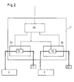
- Fig. 2 shows an application example of the method according to the invention.
- a central computer ZR is connected via electrical lines to two system areas A1 and A2, which are located in a fuel pump T.
- a system area A1 has an output unit Z1 for gasoline, the other system area A2 an output unit Z2 for diesel, wherein the output units Z1 and Z2 are here nozzle nozzles.
- the output units Z1 and Z2 are connected via hoses for dispensing the liquids with two sensors S1 and S2, which in turn are connected via electrical lines to the central computer ZR, and which are temperature sensors in this embodiment.
- the address of the associated sensor S1 can be called up via the stored assignment. If no address is assigned, the central computer detects the sensor which signals temperature changes at the moment of operation and assigns it to the system area currently being operated. Thus, an address list of all sensors is gradually created, which is used until a Sensor replacement or a re-commissioning takes place, after which the procedure starts from the beginning until all assignments have taken place.
Abstract
Description
Die vorliegende Erfindung betrifft ein Verfahren zur automatischen Zuordnung von Sensoren zu einem Systembereich in einem Zentralrechner überwachten System mit wenigstens zwei Systembereichen.The present invention relates to a method for the automatic assignment of sensors to a system area in a central computer monitored system with at least two system areas.
Bei einer Vielzahl von Vorgängen sind Gesamtsysteme in Systembereiche unterteilt, die im Prinzip alle gleichartig, gegebenenfalls parallel und/oder redundant arbeiten.In a large number of processes, entire systems are subdivided into system areas which, in principle, all work in the same way, possibly in parallel and / or redundantly.
Ein Einsatzbeispiel der vorliegenden Erfindung ist der Einsatz an einem Kraftstoffausgabesystem an einer Tankstelle. Beispielsweise sind im Bereich einer Tanksäule unterschiedliche Kraftstoffarten auszugeben, wie Diesel, Benzin usw.. Jede der Kraftstoffarten definiert einen Systembereich. Das System verfügt über einen Zentralrechner. Dieser stellt beispielsweise fest, welche der Kraftstoffarten gerade ausgegeben wird, also welcher Systembereich gerade im Einsatz ist. Der Zentralrechner wertet auch die erforderlichen Sensoren aus, wobei es sich beispielsweise um Drucksensoren, Temperatursensoren und dergleichen handeln kann.An example of an application of the present invention is the use of a fuel dispensing system at a gas station. For example, in the area of a fuel pump, different types of fuel are to be dispensed, such as diesel, gasoline, etc. Each of the fuel types defines a system area. The system has a central computer. This determines, for example, which of the fuel types is currently being output, that is, which system area is currently in use. The central computer also evaluates the required sensors, which may be, for example, pressure sensors, temperature sensors and the like.
Im Stand der Technik wird üblicherweise so vorgegangen, daß eine solche Anlage erstellt wird. Die Sensoren haben typbezogene Kennungen, d. h., sie identifizieren durch ihre Kennung, um welche Art von Sensor es sich dabei handelt. Ansonsten identifizieren sie sich zunächst mit einer allgemeinen Adresse. Bei herkömmlichen Systemen wird einfach ein Sensor auf einen bestimmten Anschlußpol einer Platine durchgeschleift und der Rechner greift schlichtweg auf diese Schnittstelle zu, um das gewünschte Sensorsignal zu erhalten und auswerten zu können.In the prior art, the procedure is usually such that such a system is created. The sensors have type-related identifiers, i. h., they identify by their identification, which type of sensor it is. Otherwise, they first identify themselves with a general address. In conventional systems, a sensor is simply looped through to a specific terminal pole of a board and the computer simply accesses this interface in order to be able to obtain and evaluate the desired sensor signal.
Bei BUS-Systemen gehen sämtliche Sensoren auf einen BUS. Hier findet die Zuordnung bei der Initialisierung üblicherweise derart statt, daß mittels einer Software im Zentralrechner der jeweilige für den Systembereich vorgesehene Sensor identifiziert wird, so daß eine feste Adresse durch die manuelle Zuordnung vergeben wird. Der Rechner legt sozusagen ein Adreßverzeichnis an und speichert dieses, fragt also je nach in Betrieb befindlichen Systembereichen die zugeordneten Adressen der zugeordneten Sensoren ab.In BUS systems, all sensors go to a BUS. Here, the assignment during initialization usually takes place in such a way that by means of software in the Central computer of each provided for the system area sensor is identified, so that a fixed address is assigned by the manual assignment. The computer creates, so to speak, an address directory and stores it, so it queries the assigned addresses of the assigned sensors, depending on the system areas in operation.
Nachteilig ist bei den bekannten Systemen, daß die Sensor-/Adreßzuordnung nach der manuellen Eingabe fixiert ist. Fällt beispielsweise ein Sensor aus, so muß dieser ausgetauscht werden. Der manuelle Adressierungsvorgang muß wiederholt werden, so daß das System insgesamt zumindest nachzuinitialisieren ist.A disadvantage of the known systems that the sensor / address assignment is fixed after manual input. For example, if a sensor fails, it must be replaced. The manual addressing process must be repeated, so that the system is at least nachinitialisieren total.
Werden beispielsweise zusätzliche Sensoren in bestehende Systeme nachgerüstet und deren Systembereichen zugeordnet, so muß von dem Zentralrechner wiederum jeder Sensor identifiziert, adressiert und dem Systembereich zugeordnet werden.If, for example, additional sensors are retrofitted into existing systems and assigned to their system areas, then in turn each sensor must be identified, addressed and assigned to the system area by the central computer.
Derartige Auswechsel- und/oder Nachrüstarbeiten müssen also von hoch qualifizierten Technikern, die sowohl Sensoren handwerklich austauschen als auch softwareseitig initialisieren können, oder von Teams durchgeführt werden.Such replacement and / or retrofitting work must therefore be carried out by highly qualified technicians, who both manually exchange sensors as well as software initialize, or by teams.
Der vorliegenden Erfindung liegt die Aufgabe zugrunde, ein Verfahren zur automatisierten Zuordnung von Sensoren zu Systembereichen in einem Zentralrechner gesteuerten bzw. Zentralrechner überwachten System bereitzustellen.The present invention has for its object to provide a method for automated assignment of sensors to system areas in a central computer controlled or central computer monitored system.
Zur technischen Lösung dieser Aufgabe wird ein Verfahren mit den Merkmalen des Patentanspruches 1 vorgeschlagen. Weitere Vorteile und Merkmale ergeben sich aus den Unteransprüchen.For the technical solution of this problem, a method with the features of
Gemäß Patentanspruch 1 wird ein Verfahren zur automatischen Zuordnung eines Sensors zu einem Systembereich in einem Zentralrechner überwachten System mit wenigstens zwei Systembereichen vorgeschlagen, dadurch gekennzeichnet, daß
- der Zentralrechner im System vorhandene Sensoren erfaßt und identifiziert,
- der Zentralrechner erfaßt, welcher Systembereich im Augenblick in Betrieb ist,
- der Zentralrechner durch den Betrieb des Systembereiches sich ergebene Änderungen von Betriebswerten der Systemsensoren erfaßt, und
- anhand der Änderungen von Betriebswerten des jeweiligen Sensors diesen Sensor dem in Betrieb befindliche Systembereich automatisch zuordnet.
- the central computer detects and identifies existing sensors in the system,
- the central computer detects which system area is currently in operation,
- the central computer was devoted to the operation of the system area Detects changes in operating values of the system sensors, and
- Based on the changes in operating values of the respective sensor automatically assigns this sensor to the operating system area in operation.
Der wesentliche Vorteil des erfindungsgemäßen Verfahrens ist, daß eine automatische Adreßzuordnung von Sensoren durch den Zentralrechner erfolgt, somit ein manueller Adressierungsvorgang entfällt und zudem die Adreßzuordnung nicht fixiert ist. Durch diese Überwachung des Systems mittels eines Zentralrechners, ist bei eventuellen Auswechsel- und/oder Nachrüstarbeiten kein hochqualifiziertes Personal nötig, wodurch die Betriebskosten eines solchen Systems deutlich gesenkt werden.The main advantage of the method according to the invention is that an automatic address assignment of sensors by the central computer, thus eliminating a manual addressing process and also the address assignment is not fixed. By monitoring the system by means of a central computer, no replacement or retrofitting work requires highly qualified personnel, which significantly reduces the operating costs of such a system.
Erfindungsgemäß erfaßt der Zentralrechner die im System vorhandenen Sensoren und identifiziert diese zum Beispiel anhand der typbedingten Kennung. Weiterhin erfaßt der Zentralrechner, welcher Systembereich im Augenblick in Betrieb ist, und die sich durch diesen Betrieb ergebende Änderungen der Systemsensoren. Danach wird anhand der Änderungen des jeweiligen Sensors dieser Sensor dem in Betrieb befindlichen Systembereich automatisch zugeordnet. Das Verfahren wird durchlaufen, wenn der Zentralrechner die im System vorhandenen Sensoren erfaßt, diese Erfassung mit abgespeicherten Adressen der Sensoren vergleicht und feststellt, daß Sensoren im System vorhanden sind, denen keine Adresse zugeordnet ist.According to the invention, the central computer detects the sensors present in the system and identifies them, for example, on the basis of the type-related identifier. Furthermore, the central computer detects which system area is currently in operation and changes in the system sensors resulting from this operation. Thereafter, based on the changes of the respective sensor, this sensor is automatically assigned to the system area in operation. The process is run when the central computer detects the sensors present in the system, compares this detection with stored addresses of the sensors and determines that there are sensors in the system to which no address is assigned.
Eine vorteilhafte Ausgestaltung der Erfindung sieht vor, daß die Zuordnung gespeichert wird. Dadurch liegt die Zuordnung bei folgenden Anwendungen des Gesamtsystems vor, so daß ein direkter Zugriff auf die gespeicherten Daten erfolgen kann, und kein erneuter Ablauf des Verfahrens bezüglich der vorgenommenen Zuordnungen nötig ist, solange keine Änderung hinsichtlich der Sensoren vorliegt. Sobald der Sensor ein Signal an den Zentralrechner sendet, erkennt dieser den zugehörigen in Betrieb befindlichen Systembereich, und umgekehrt, und kann weitere Datenverarbeitungen vollziehen.An advantageous embodiment of the invention provides that the assignment is stored. As a result, the allocation is present in the following applications of the overall system, so that a direct access to the stored data can be made, and no re-run of the method with respect to the assignments made necessary, as long as there is no change in the sensors. As soon as the sensor transmits a signal to the central computer, it recognizes the associated operating system area, and vice versa, and can carry out further data processing.
Nach einer weiteren vorteilhaften Ausgestaltung der Erfindung weist der Zentralrechner dem identifizierten und zugeordneten Sensor eine eindeutige Adresse zu. Dadurch wird im Zentralrechner ein Adreßverzeichnis angelegt, so daß je nach Betrieb eines Systembereiches die zugeordnete Adresse des zugeordneten Sensors abgerufen werden kann.According to a further advantageous embodiment of the invention, the central computer to the identified and associated sensor to a unique address. As a result, an address list is created in the central computer, so that depending on the operation of a system area, the associated address of the associated sensor can be retrieved.
Nach einer weiteren vorteilhaften Ausgestaltung der Erfindung wird das erfindungsgemäße Verfahren in einem System zur Waren-/Produktausgabe angewandt, wobei die unterschiedlichen Systembereiche durch unterschiedliche Waren-/Produkte gebildet werden.According to a further advantageous embodiment of the invention, the inventive method is applied in a system for goods / product output, wherein the different system areas are formed by different goods / products.
Eine weitere vorteilhafte Ausgestaltung der Erfindung sieht vor, daß das Verfahren in einem System zur Ausgabe von Kraftstoffen angewandt wird, wobei die unterschiedlichen Systembereiche durch die unterschiedlichen Kraftstoffe identifiziert werden.A further advantageous embodiment of the invention provides that the method is used in a system for dispensing fuels, wherein the different system areas are identified by the different fuels.
Nach einer weiteren vorteilhaften Ausgestaltung der Erfindung werden als Sensoren Temperatursensoren eingesetzt. Diese können zum Beispiel bei Systemen zur Ausgabe von Kraftstoffen Temperaturänderungen bei Ausgabe feststellen, wodurch der Zentralrechner eine Zuordnung des Sensors zu der entsprechenden durch einen Systembereich ausgegebenen Kraftstoffsorte vollziehen kann.According to a further advantageous embodiment of the invention, temperature sensors are used as sensors. For example, in fuel dispensing systems, these may detect temperature changes on output, allowing the central computer to map the sensor to the appropriate type of fuel dispensed by a system area.
Eine weitere vorteilhafte Ausgestaltung der Erfindung sieht vor, daß das Verfahren bei Inbetriebnahme eines Systems und nach jedem Sensorwechsel durchgeführt wird. Dadurch wird jedesmal ein neues Adreßverzeichnis angelegt, welches den Änderungen im Gesamtsystem Rechnung trägt. Zudem ist kein hochqualifiziertes Personal notwendig, welches die Änderungen am Gesamtsystem manuell eingibt, so daß die Betriebskosten eines das Verfahren aufweisenden Systems gesenkt werden.A further advantageous embodiment of the invention provides that the method is carried out when commissioning a system and after each sensor change. As a result, a new address list is created each time, which takes into account the changes in the overall system. In addition, no highly skilled personnel is necessary, which manually inputs the changes to the overall system, so that the operating costs of a system having the method are lowered.
Weitere Vorteile und Merkmale der Erfindung werden im Folgenden anhand der Figuren beschrieben. Dabei zeigt
- Fig. 1
- ein Ausführungsbeispiel für das erfindungsgemäße Verfahren, und
- Fig. 2
- ein Ausführungsbeispiel eines mit dem erfindungsgemäßen Verfahren betriebenen System.
- Fig. 1
- an embodiment of the inventive method, and
- Fig. 2
- an embodiment of a system operated by the method according to the invention.
Fig. 1 zeigt ein Schema des Verfahrensablaufs. Das Verfahren wird angewandt, wenn in dem verwendeten Gesamtsystem ein Sensorwechsel erfolgt ist oder dieses System in Betrieb genommen wird. Zu diesem Zeitpunkt liegen keine Zuordnungen von Sensoren zu Systembereichen vor, auf die der Zentralrechner zugreifen könnte. Dann folgt im Schritt 1 die Erfassung von im System vorhandenen Sensoren und deren Identifizierung anhand der typbedingten Kennung. Als nächstes erfolgt in Schritt 2 die Erfassung des im Augenblick in Betrieb befindlichen Systembereiches, dem zum Beispiel eine bestimmte Kraftstoff- oder Produktausgabe zugeordnet ist. In Schritt 3 erfolgt die Erfassung von Änderungen an einem Sensor, die durch den Betrieb des zugehörigen Systembereiches erzeugt werden. In Schritt 4 erfolgt durch den Zentralrechner die Zuordnung des Sensors, an dem Änderungen festgestellt wurden, zu dem zugehörigen Systembereich, welcher sich im Augenblick in Betrieb befindet. Im darauf folgenden Schritt 5A erfolgt das Abspeichern der in Schritt 4 erstellten Zuordnung, welche bis zur nächsten Inbetriebnahme oder zum nächsten Sensorwechsel als Basis zur weiteren Datenverarbeitung dient. Zudem weist der Zentralrechner in Schritt 5B dem identifizierten und zugeordneten Sensor eine eindeutige Adresse zu, die bei einem in Betrieb befindlicher Systembereich bei Verwendung der abgespeicherten Zuordnung direkt abgerufen werden kann, wonach eine weitere Datenverarbeitung durch den Zentralrechner erfolgen kann. Weiterhin ist es möglich, daß die Schritte 2 und 3 zeitlich vertauscht werden oder parallel erfolgen.Fig. 1 shows a diagram of the procedure. The method is used when in the overall system used a sensor change has been made or this system is put into operation. At this time, there are no sensor-to-system mappings that the central computer could access. This is followed in
Fig. 2 zeigt ein Anwendungsbeispiel für das erfindungsgemäße Verfahren. In diesem Beispiel ist ein Zentralrechner ZR über elektrische Leitungen mit zwei Systembereichen A1 und A2 verbunden, welche sich in einer Tanksäule T befinden. Ein Systembereich A1 weist eine Ausgabeeinheit Z1 für Benzin, der andere Systembereich A2 eine Ausgabeeinheit Z2 für Diesel auf, wobei die Ausgabeeinheiten Z1 und Z2 hier Zapfpistolen sind. Weiterhin sind die Ausgabeeinheiten Z1 und Z2 über Schläuche zur Ausgabe der Flüssigkeiten mit zwei Sensoren S1 und S2 verbunden, welche wiederum über elektrische Leitungen mit dem Zentralrechner ZR verbunden sind, und die in dieser Ausführung Temperatursensoren sind. Wird nun dieses System zur Ausgabe eines Kraftstoffs in Betrieb genommen, oder wurde einer der Sensoren S1 und/oder S2 ausgewechselt, muß zuerst von dem Zentralrechner ZR eine Erfassung und Identifizierung der in System vorhandenen Sensoren S1 und S2 erfolgen. Wird nun an der Ausgabeeinheit Z1 des Systembereichs A1 Benzin entnommen, so wird der Betrieb dieses Systembereichs A1 von dem Zentralrechner ZR erfaßt. Weiterhin wird bei der Benzinausgabe durch den Flüssigkeitsstrom eine Temperaturänderung an dem Sensor S1 erzeugt, welche ebenfalls von dem Zentralrechner ZR erfaßt wird. Dieser ordnet nun den Sensor S1 dem Systembereich A1 zu, speichert diese Zuordnung ab und weist dem Sensor S1 gleichzeitig eine eindeutige Adresse zu. Wird nun der Systembereich A1 1 im Folgenden betrieben, so kann über die abgespeicherte Zuordnung die Adresse des zugehörigen Sensors S1 abgerufen werden. Ist keine Adresse zugeordnet, so erfaßt der Zentralrechner den im Augenblick des Betriebs Temperaturänderungen signalisierenden Sensor und ordnet diesen dem im Augenblick betriebenen Systembereich zu. So wird nach und nach ein Adreßverzeichnis aller Sensoren angelegt, welches Verwendung findet, bis ein Sensorwechsel oder eine erneute Inbetriebnahme erfolgt, wonach das Verfahren von vorne beginnt, bis alle Zuordnungen stattgefunden haben.Fig. 2 shows an application example of the method according to the invention. In this example, a central computer ZR is connected via electrical lines to two system areas A1 and A2, which are located in a fuel pump T. A system area A1 has an output unit Z1 for gasoline, the other system area A2 an output unit Z2 for diesel, wherein the output units Z1 and Z2 are here nozzle nozzles. Furthermore, the output units Z1 and Z2 are connected via hoses for dispensing the liquids with two sensors S1 and S2, which in turn are connected via electrical lines to the central computer ZR, and which are temperature sensors in this embodiment. Now, if this system is put into operation for dispensing a fuel, or was one of the sensors S1 and / or S2 replaced, must first be carried out by the central computer ZR detection and identification of existing sensors in the system S1 and S2. If gas is now taken from the dispensing unit Z1 of the system area A1, the operation of this system area A1 is detected by the central computer ZR. Furthermore, in the gasoline dispensing by the liquid flow, a temperature change is generated at the sensor S1, which is also detected by the central computer ZR. This now assigns the sensor S1 to the system area A1, stores this assignment and assigns the sensor S1 at the same time a unique address. If the
- A1A1
- Systembereich für BenzinSystem area for gasoline
- A2A2
- Systembereich für DieselSystem area for diesel
- TT
- Tanksäulepetrol pump
- S1S1
- Sensor der BenzinausgabeSensor of gasoline dispensing
- S2S2
- Sensor der DieselausgabeSensor of the diesel edition
- ZRZR
- Zentralrechnermainframe
- Z1Z1
- Ausgabeeinheit für BenzinOutput unit for gasoline
- Z2Z2
- Ausgabeeinheit für DieselOutput unit for diesel
- Ee
- ErdtankUnderground tank
Claims (7)
dadurch gekennzeichnet, daß
characterized in that
Priority Applications (4)
| Application Number | Priority Date | Filing Date | Title |
|---|---|---|---|
| EP06020079A EP1905732B1 (en) | 2006-09-26 | 2006-09-26 | Method for automatic allocation of sensors |
| DE502006003336T DE502006003336D1 (en) | 2006-09-26 | 2006-09-26 | Method for automatic assignment of sensors |
| RU2007134855/08A RU2406104C2 (en) | 2006-09-26 | 2007-09-20 | Method for automatic distribution of sensors |
| UAA200710413A UA88057C2 (en) | 2006-09-26 | 2007-09-20 | Method for automated distribution of indicators |
Applications Claiming Priority (1)
| Application Number | Priority Date | Filing Date | Title |
|---|---|---|---|
| EP06020079A EP1905732B1 (en) | 2006-09-26 | 2006-09-26 | Method for automatic allocation of sensors |
Publications (2)
| Publication Number | Publication Date |
|---|---|
| EP1905732A1 true EP1905732A1 (en) | 2008-04-02 |
| EP1905732B1 EP1905732B1 (en) | 2009-04-01 |
Family
ID=37806067
Family Applications (1)
| Application Number | Title | Priority Date | Filing Date |
|---|---|---|---|
| EP06020079A Expired - Fee Related EP1905732B1 (en) | 2006-09-26 | 2006-09-26 | Method for automatic allocation of sensors |
Country Status (4)
| Country | Link |
|---|---|
| EP (1) | EP1905732B1 (en) |
| DE (1) | DE502006003336D1 (en) |
| RU (1) | RU2406104C2 (en) |
| UA (1) | UA88057C2 (en) |
Citations (4)
| Publication number | Priority date | Publication date | Assignee | Title |
|---|---|---|---|---|
| US5519878A (en) * | 1992-03-18 | 1996-05-21 | Echelon Corporation | System for installing and configuring (grouping and node address assignment) household devices in an automated environment |
| EP0974940A2 (en) * | 1998-07-21 | 2000-01-26 | Gilbarco Inc. | Apparatus and method for using a transponder as an information buffer |
| EP1338446A2 (en) * | 2002-02-18 | 2003-08-27 | Toyota Jidosha Kabushiki Kaisha | Vehicle tire information obtaining apparatus and tire information processing apparatus |
| WO2004082243A1 (en) * | 2003-03-13 | 2004-09-23 | 777388 Ontario Limited | Auto-addressing mechanism for a networked system |
-
2006
- 2006-09-26 EP EP06020079A patent/EP1905732B1/en not_active Expired - Fee Related
- 2006-09-26 DE DE502006003336T patent/DE502006003336D1/en active Active
-
2007
- 2007-09-20 RU RU2007134855/08A patent/RU2406104C2/en not_active IP Right Cessation
- 2007-09-20 UA UAA200710413A patent/UA88057C2/en unknown
Patent Citations (4)
| Publication number | Priority date | Publication date | Assignee | Title |
|---|---|---|---|---|
| US5519878A (en) * | 1992-03-18 | 1996-05-21 | Echelon Corporation | System for installing and configuring (grouping and node address assignment) household devices in an automated environment |
| EP0974940A2 (en) * | 1998-07-21 | 2000-01-26 | Gilbarco Inc. | Apparatus and method for using a transponder as an information buffer |
| EP1338446A2 (en) * | 2002-02-18 | 2003-08-27 | Toyota Jidosha Kabushiki Kaisha | Vehicle tire information obtaining apparatus and tire information processing apparatus |
| WO2004082243A1 (en) * | 2003-03-13 | 2004-09-23 | 777388 Ontario Limited | Auto-addressing mechanism for a networked system |
Also Published As
| Publication number | Publication date |
|---|---|
| DE502006003336D1 (en) | 2009-05-14 |
| UA88057C2 (en) | 2009-09-10 |
| RU2007134855A (en) | 2009-03-27 |
| RU2406104C2 (en) | 2010-12-10 |
| EP1905732B1 (en) | 2009-04-01 |
Similar Documents
| Publication | Publication Date | Title |
|---|---|---|
| EP0730803B1 (en) | Device for exchanging data | |
| EP0789864B1 (en) | Monitoring system for an industrial plant | |
| DE102014208611A1 (en) | Method for diagnosing a condition in a vehicle and diagnostic test device | |
| DE102019100788A1 (en) | Leakage monitoring method for a compressed air system | |
| EP3193311A1 (en) | Rail vehicle component group and method for generating a life cycle of a machine component and service method for maintenance | |
| DE10252278B4 (en) | System-integrated bus monitor | |
| DE19548684B4 (en) | Method for detecting and documenting exhaust-related malfunctions of a vehicle with an internal combustion engine using on-board means | |
| EP1905732B1 (en) | Method for automatic allocation of sensors | |
| EP0894255A1 (en) | Process and device for controlling a test track system for motor vehicles | |
| DE102010024275A1 (en) | Maintenance tracking system | |
| DE102007046050A1 (en) | Data transmission system with data transmission lines and method for establishing port-to-port connections in this data transmission system | |
| DE102014011836A1 (en) | Device for filling vehicle air conditioning systems with refrigerant R744 | |
| DE102019205691A1 (en) | System and method for the simulation of industrial processes | |
| EP3341807B1 (en) | Method and system for maintaining field devices in an automation plant | |
| DE102018005262A1 (en) | Process for component-independent failure mode and influence analysis (FMEA) | |
| EP2090947A1 (en) | Method for specifying field device addresses | |
| DE102010052192A1 (en) | Method for addressing multi-slaves of e.g. sensor in actuator sensor-interface, involves holding remaining partial-slaves in inactive condition, and providing multi-slaves of type with same combination of profiles of partial-slaves | |
| DE102019005352A1 (en) | Availability monitoring procedures | |
| DE2907607A1 (en) | CLOCK CALCULATION ARRANGEMENT AND THE PROCEDURE THAT CAN BE EXECUTED TO MAINTAIN A REAL-TIME CLOCK | |
| EP2360632A1 (en) | Maintenance system | |
| DE102009010795A1 (en) | Coupling of ERP systems with process control systems for the automated transmission of plant structures and plant data | |
| DE102018125064A1 (en) | Process for reducing errors in textile machines | |
| DE102018100364A1 (en) | Method for operating a spinning or winding machine | |
| WO2018065223A1 (en) | Method and device for ascertaining the damaged state of a component of a vehicle | |
| DE102015202205A1 (en) | Method for checking coupling parameters of a coupling system |
Legal Events
| Date | Code | Title | Description |
|---|---|---|---|
| PUAI | Public reference made under article 153(3) epc to a published international application that has entered the european phase |
Free format text: ORIGINAL CODE: 0009012 |
|
| 17P | Request for examination filed |
Effective date: 20070828 |
|
| AK | Designated contracting states |
Kind code of ref document: A1 Designated state(s): AT BE BG CH CY CZ DE DK EE ES FI FR GB GR HU IE IS IT LI LT LU LV MC NL PL PT RO SE SI SK TR |
|
| AX | Request for extension of the european patent |
Extension state: AL BA HR MK YU |
|
| GRAP | Despatch of communication of intention to grant a patent |
Free format text: ORIGINAL CODE: EPIDOSNIGR1 |
|
| GRAS | Grant fee paid |
Free format text: ORIGINAL CODE: EPIDOSNIGR3 |
|
| AKX | Designation fees paid |
Designated state(s): DE FR GB IT |
|
| GRAA | (expected) grant |
Free format text: ORIGINAL CODE: 0009210 |
|
| AK | Designated contracting states |
Kind code of ref document: B1 Designated state(s): DE FR GB IT |
|
| REG | Reference to a national code |
Ref country code: GB Ref legal event code: FG4D Free format text: NOT ENGLISH |
|
| REF | Corresponds to: |
Ref document number: 502006003336 Country of ref document: DE Date of ref document: 20090514 Kind code of ref document: P |
|
| PLBE | No opposition filed within time limit |
Free format text: ORIGINAL CODE: 0009261 |
|
| STAA | Information on the status of an ep patent application or granted ep patent |
Free format text: STATUS: NO OPPOSITION FILED WITHIN TIME LIMIT |
|
| 26N | No opposition filed |
Effective date: 20100105 |
|
| PGFP | Annual fee paid to national office [announced via postgrant information from national office to epo] |
Ref country code: GB Payment date: 20120920 Year of fee payment: 7 |
|
| PGFP | Annual fee paid to national office [announced via postgrant information from national office to epo] |
Ref country code: FR Payment date: 20121010 Year of fee payment: 7 |
|
| PGFP | Annual fee paid to national office [announced via postgrant information from national office to epo] |
Ref country code: IT Payment date: 20120925 Year of fee payment: 7 |
|
| GBPC | Gb: european patent ceased through non-payment of renewal fee |
Effective date: 20130926 |
|
| REG | Reference to a national code |
Ref country code: FR Ref legal event code: ST Effective date: 20140530 |
|
| PG25 | Lapsed in a contracting state [announced via postgrant information from national office to epo] |
Ref country code: GB Free format text: LAPSE BECAUSE OF NON-PAYMENT OF DUE FEES Effective date: 20130926 |
|
| PG25 | Lapsed in a contracting state [announced via postgrant information from national office to epo] |
Ref country code: IT Free format text: LAPSE BECAUSE OF NON-PAYMENT OF DUE FEES Effective date: 20130926 Ref country code: FR Free format text: LAPSE BECAUSE OF NON-PAYMENT OF DUE FEES Effective date: 20130930 |
|
| PGFP | Annual fee paid to national office [announced via postgrant information from national office to epo] |
Ref country code: DE Payment date: 20151123 Year of fee payment: 10 |
|
| REG | Reference to a national code |
Ref country code: DE Ref legal event code: R119 Ref document number: 502006003336 Country of ref document: DE |
|
| PG25 | Lapsed in a contracting state [announced via postgrant information from national office to epo] |
Ref country code: DE Free format text: LAPSE BECAUSE OF NON-PAYMENT OF DUE FEES Effective date: 20170401 |