EP1906470A2 - Cordless power tool battery and charging system therefore - Google Patents
Cordless power tool battery and charging system therefore Download PDFInfo
- Publication number
- EP1906470A2 EP1906470A2 EP07120111A EP07120111A EP1906470A2 EP 1906470 A2 EP1906470 A2 EP 1906470A2 EP 07120111 A EP07120111 A EP 07120111A EP 07120111 A EP07120111 A EP 07120111A EP 1906470 A2 EP1906470 A2 EP 1906470A2
- Authority
- EP
- European Patent Office
- Prior art keywords
- battery
- charging system
- power tool
- cordless power
- charging
- Prior art date
- Legal status (The legal status is an assumption and is not a legal conclusion. Google has not performed a legal analysis and makes no representation as to the accuracy of the status listed.)
- Granted
Links
Images


Classifications
-
- H—ELECTRICITY
- H01—ELECTRIC ELEMENTS
- H01M—PROCESSES OR MEANS, e.g. BATTERIES, FOR THE DIRECT CONVERSION OF CHEMICAL ENERGY INTO ELECTRICAL ENERGY
- H01M50/00—Constructional details or processes of manufacture of the non-active parts of electrochemical cells other than fuel cells, e.g. hybrid cells
- H01M50/20—Mountings; Secondary casings or frames; Racks, modules or packs; Suspension devices; Shock absorbers; Transport or carrying devices; Holders
- H01M50/247—Mountings; Secondary casings or frames; Racks, modules or packs; Suspension devices; Shock absorbers; Transport or carrying devices; Holders specially adapted for portable devices, e.g. mobile phones, computers, hand tools or pacemakers
-
- H—ELECTRICITY
- H01—ELECTRIC ELEMENTS
- H01M—PROCESSES OR MEANS, e.g. BATTERIES, FOR THE DIRECT CONVERSION OF CHEMICAL ENERGY INTO ELECTRICAL ENERGY
- H01M10/00—Secondary cells; Manufacture thereof
- H01M10/42—Methods or arrangements for servicing or maintenance of secondary cells or secondary half-cells
- H01M10/4207—Methods or arrangements for servicing or maintenance of secondary cells or secondary half-cells for several batteries or cells simultaneously or sequentially
-
- H—ELECTRICITY
- H01—ELECTRIC ELEMENTS
- H01M—PROCESSES OR MEANS, e.g. BATTERIES, FOR THE DIRECT CONVERSION OF CHEMICAL ENERGY INTO ELECTRICAL ENERGY
- H01M10/00—Secondary cells; Manufacture thereof
- H01M10/42—Methods or arrangements for servicing or maintenance of secondary cells or secondary half-cells
- H01M10/425—Structural combination with electronic components, e.g. electronic circuits integrated to the outside of the casing
-
- H—ELECTRICITY
- H01—ELECTRIC ELEMENTS
- H01M—PROCESSES OR MEANS, e.g. BATTERIES, FOR THE DIRECT CONVERSION OF CHEMICAL ENERGY INTO ELECTRICAL ENERGY
- H01M10/00—Secondary cells; Manufacture thereof
- H01M10/42—Methods or arrangements for servicing or maintenance of secondary cells or secondary half-cells
- H01M10/44—Methods for charging or discharging
-
- H—ELECTRICITY
- H01—ELECTRIC ELEMENTS
- H01M—PROCESSES OR MEANS, e.g. BATTERIES, FOR THE DIRECT CONVERSION OF CHEMICAL ENERGY INTO ELECTRICAL ENERGY
- H01M10/00—Secondary cells; Manufacture thereof
- H01M10/42—Methods or arrangements for servicing or maintenance of secondary cells or secondary half-cells
- H01M10/48—Accumulators combined with arrangements for measuring, testing or indicating the condition of cells, e.g. the level or density of the electrolyte
- H01M10/482—Accumulators combined with arrangements for measuring, testing or indicating the condition of cells, e.g. the level or density of the electrolyte for several batteries or cells simultaneously or sequentially
-
- H—ELECTRICITY
- H01—ELECTRIC ELEMENTS
- H01M—PROCESSES OR MEANS, e.g. BATTERIES, FOR THE DIRECT CONVERSION OF CHEMICAL ENERGY INTO ELECTRICAL ENERGY
- H01M50/00—Constructional details or processes of manufacture of the non-active parts of electrochemical cells other than fuel cells, e.g. hybrid cells
- H01M50/20—Mountings; Secondary casings or frames; Racks, modules or packs; Suspension devices; Shock absorbers; Transport or carrying devices; Holders
- H01M50/204—Racks, modules or packs for multiple batteries or multiple cells
-
- H—ELECTRICITY
- H01—ELECTRIC ELEMENTS
- H01M—PROCESSES OR MEANS, e.g. BATTERIES, FOR THE DIRECT CONVERSION OF CHEMICAL ENERGY INTO ELECTRICAL ENERGY
- H01M50/00—Constructional details or processes of manufacture of the non-active parts of electrochemical cells other than fuel cells, e.g. hybrid cells
- H01M50/20—Mountings; Secondary casings or frames; Racks, modules or packs; Suspension devices; Shock absorbers; Transport or carrying devices; Holders
- H01M50/267—Mountings; Secondary casings or frames; Racks, modules or packs; Suspension devices; Shock absorbers; Transport or carrying devices; Holders having means for adapting to batteries or cells of different types or different sizes
-
- H—ELECTRICITY
- H01—ELECTRIC ELEMENTS
- H01M—PROCESSES OR MEANS, e.g. BATTERIES, FOR THE DIRECT CONVERSION OF CHEMICAL ENERGY INTO ELECTRICAL ENERGY
- H01M50/00—Constructional details or processes of manufacture of the non-active parts of electrochemical cells other than fuel cells, e.g. hybrid cells
- H01M50/20—Mountings; Secondary casings or frames; Racks, modules or packs; Suspension devices; Shock absorbers; Transport or carrying devices; Holders
- H01M50/296—Mountings; Secondary casings or frames; Racks, modules or packs; Suspension devices; Shock absorbers; Transport or carrying devices; Holders characterised by terminals of battery packs
-
- H—ELECTRICITY
- H02—GENERATION; CONVERSION OR DISTRIBUTION OF ELECTRIC POWER
- H02J—CIRCUIT ARRANGEMENTS OR SYSTEMS FOR SUPPLYING OR DISTRIBUTING ELECTRIC POWER; SYSTEMS FOR STORING ELECTRIC ENERGY
- H02J7/00—Circuit arrangements for charging or depolarising batteries or for supplying loads from batteries
- H02J7/00032—Circuit arrangements for charging or depolarising batteries or for supplying loads from batteries characterised by data exchange
- H02J7/00036—Charger exchanging data with battery
-
- H—ELECTRICITY
- H02—GENERATION; CONVERSION OR DISTRIBUTION OF ELECTRIC POWER
- H02J—CIRCUIT ARRANGEMENTS OR SYSTEMS FOR SUPPLYING OR DISTRIBUTING ELECTRIC POWER; SYSTEMS FOR STORING ELECTRIC ENERGY
- H02J7/00—Circuit arrangements for charging or depolarising batteries or for supplying loads from batteries
- H02J7/00047—Circuit arrangements for charging or depolarising batteries or for supplying loads from batteries with provisions for charging different types of batteries
-
- H—ELECTRICITY
- H01—ELECTRIC ELEMENTS
- H01M—PROCESSES OR MEANS, e.g. BATTERIES, FOR THE DIRECT CONVERSION OF CHEMICAL ENERGY INTO ELECTRICAL ENERGY
- H01M10/00—Secondary cells; Manufacture thereof
- H01M10/05—Accumulators with non-aqueous electrolyte
- H01M10/052—Li-accumulators
-
- H—ELECTRICITY
- H01—ELECTRIC ELEMENTS
- H01M—PROCESSES OR MEANS, e.g. BATTERIES, FOR THE DIRECT CONVERSION OF CHEMICAL ENERGY INTO ELECTRICAL ENERGY
- H01M10/00—Secondary cells; Manufacture thereof
- H01M10/24—Alkaline accumulators
- H01M10/30—Nickel accumulators
-
- H—ELECTRICITY
- H01—ELECTRIC ELEMENTS
- H01M—PROCESSES OR MEANS, e.g. BATTERIES, FOR THE DIRECT CONVERSION OF CHEMICAL ENERGY INTO ELECTRICAL ENERGY
- H01M10/00—Secondary cells; Manufacture thereof
- H01M10/42—Methods or arrangements for servicing or maintenance of secondary cells or secondary half-cells
- H01M10/4221—Methods or arrangements for servicing or maintenance of secondary cells or secondary half-cells with battery type recognition
-
- Y—GENERAL TAGGING OF NEW TECHNOLOGICAL DEVELOPMENTS; GENERAL TAGGING OF CROSS-SECTIONAL TECHNOLOGIES SPANNING OVER SEVERAL SECTIONS OF THE IPC; TECHNICAL SUBJECTS COVERED BY FORMER USPC CROSS-REFERENCE ART COLLECTIONS [XRACs] AND DIGESTS
- Y02—TECHNOLOGIES OR APPLICATIONS FOR MITIGATION OR ADAPTATION AGAINST CLIMATE CHANGE
- Y02E—REDUCTION OF GREENHOUSE GAS [GHG] EMISSIONS, RELATED TO ENERGY GENERATION, TRANSMISSION OR DISTRIBUTION
- Y02E60/00—Enabling technologies; Technologies with a potential or indirect contribution to GHG emissions mitigation
- Y02E60/10—Energy storage using batteries
Definitions
- the present invention relates to cordless power tools, and more particularly, to batteries for cordless power tools and a charging system for charging such batteries.
- Cordless power tools are well-known and provide several advantages over traditional corded power tools.
- One of the advantages provided by cordless power tools is the mobility and/or portability when using the tool. For example, the operator of the cordless power tool can quickly and efficiently work over a larger area without having to continually adjust the power cord. Similarly, cordless power tools can be used in areas where electrical power is not available. Because of these advantages, the popularity of cordless power tools has increased among both professional and novice power tool users.
- the invention may provide a cordless power tool battery including an onboard circuit configured to electronically communicate with an associated battery charging system.
- the onboard circuit may contain identifying indicia relating to the battery chemistry, the battery voltage, the battery capacity and the like.
- the onboard circuit may contain a charging protocol specific to the battery.
- the onboard circuit may be configured to store data related to the battery, for example, a counter of the number of charges, a history of discharge and charge cycles, a history of battery renewing and the like.
- the onboard circuit may be configured to communicate with the charging system even if the battery has no voltage.
- the invention may provide a cordless power tool battery charging system.
- the charging system may be configured to accept multiple input voltages.
- the charging system may be configured to charge batteries having different battery chemistries.
- the charging system may be configured to charge batteries having different voltages.
- the charging system may be configured to charge batteries in accordance with a charging protocol stored in the battery.
- the charging system may be configured to display the current charge level of a battery.
- the charging system may be configured to compare a current capacity of a battery to an original capacity of a battery and, based thereon, recommend whether the battery should be renewed. In one or more embodiments of the invention, the charging system may be configured to renew a battery by deep discharging the battery and then recharging the battery.
- the invention may provide a cordless power tool battery charging system configured to receive batteries having different housing configurations.
- the charging system may include keyways configured to receive various battery key patterns.
- the charging system may be configured such that the battery contacts and charging system contacts are disengaged prior to removal of the battery from the charging system.
- the batteries may include an onboard circuit contact on a distal end surface thereof for contact with a corresponding contact in the charging system.
- the charging system may include flexible battery contacts such that the battery contacts within the charging system housing.
- the charging system may include a patterned heat sink extending therein.
- the charging system may include a fan mounted on a heat sink and wherein the heat sink may further include through passages aligned with the fan.
- FIG. 1 two exemplary battery packs 10, 10' of the present invention are shown.
- the battery pack 10 illustrated in Fig. 1 utilizes Nickel Cadmium battery cells while the battery pack 10' illustrated in Figs. 2 and 3 utilizes Lithium Ion battery cells.
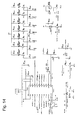
- Exemplary circuit diagrams for both battery packs 10 and 10' are illustrated in Figs. 11 and 12, respectively.
- Each battery pack 10, 10' includes a main housing 12 with a stem portion 14 extending therefrom.
- the main housing 12 and the stem portion 14 house the battery cells (not shown).
- the stem portion 14 preferably houses one or more of the battery cells.
- the stem portion 14 has a cylindrical body 13 extending from the main housing 12 to an end cap 15.
- a pair of opposed openings 17 are provided in the body 13 adjacent to the end cap 15. The number and position of the openings 17 may be varied.
- the openings 17 are configured to expose the battery electrical contacts 16A and 16B which are electrically interconnected with the battery cells and the battery communication contact 18 which is electrically interconnected with the battery onboard circuit 20.
- each battery pack 10 and 10' includes various support keys 22 and alignment keys 24 extending radially outward from the stem portion body 13.
- the support keys 22 are configured to align with and rotatably engage support keyways in various portable tools.
- the support keys 22 and the alignment keys 24 can be arranged in various configurations, including different widths, heights, positions, numbers and the like.
- the configuration of the support keys 22 and alignment key 24 are configured such that the battery pack 10, 10' is properly aligned with the power tool or charging system 50, as will be described hereinafter, such that the proper polarity of the contacts 16A and 16B is maintained.
- each specific support key 22 and alignment key 24 configuration corresponds to a battery pack 10, 10' having a specific voltage such that the battery pack 10, 10' is useable only in power tools requiring such voltage and having corresponding keyways to receive the battery pack 10, 10'. Since the configuration of the keys 22 and the alignment keyway 24 are distinct for each voltage, the different voltage battery packs would not be capable of inadvertent use with the wrong tool.
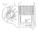
- the charging system 50 generally includes a housing 52 comprising a top cover 51 and a bottom cover 53.
- a battery stem receiving opening 60 is defined through the top cover 51.
- the opening 60 includes one or more support key keyways 62 and one or more alignment key keyways 64.
- the keyways 62 and 64 are configured to receive various configurations of battery pack support keys 22 and alignment keys 24, such that the charging system 50 provides a universal charger for various battery voltages.
- the support key keyways 62 are typically wider than most, if not all of the support keys 22, such that, relative to other voltage key configurations, the keys 22 can be moved circumferentially and still align with the keyways 62.
- Stops 66 are preferably provided within the opening 60 such that the battery pack stem 14 can only be rotated a given amount within the opening 60.
- the charging system 50 preferably includes a plug port 65 with male pins 67 configured to mate with the female plug of cords (not shown) useable with different input voltages. As illustrated in the circuit diagrams, the male pins 67 are associated with a voltage converter which allows the charging system to be utilized with different input voltages.
- the charging system 50 includes a pair of opposed electrical contacts 72A and 72B configured to electrically connect with the battery pack contacts 16A and 16B.
- the configuration of the support keys 22 and alignment key 24 and the keyways 62 and 64 are configured such that the battery pack 10, 10' is properly aligned with the charging system 50 such that the proper polarity of the contacts 16A and 16B is maintained.
- Each electrical contact 16A, 16B preferably includes a radially tapered portion 19 extending to an arcuate portion 21.
- the tapered portions 19 are configured to first contact the charger contacts 72A and 72B during rotation of the battery pack 10, 10' relative to the charging system 50 such that the charger contacts 72A, 72B ride along the tapered portions 19 and into final engagement with the arcuate portion 21.
- the tapered portion 19 may be made from conductive material, or alternatively, may be a non-conductive material.
- the battery pack contacts 16A and 16B are circumferentially offset from and thereby disengaged from the charger contacts 72A and 72B. As such, during axial movement of the battery pack stem 14 into the opening 60, the contacts 16A, 16B and 72A, 72B do not interfere with each other or apply any load upon each other.
- a communication contact 74 extends from the circuit board 80 within the charging system 50 and is configured to engage the battery communication contact 18. Electrical connection between the battery communication contact 18 and the communication contact 74 provides a digital link between the onboard circuit 20 in the battery pack 10, 10' and a microprocessor 90 or the like in the charging system 50.
- An exemplary onboard circuit 20 is the DS2438 manufactured by Dallas Semiconductor, the specifications of which are incorporated herein by reference. The functions of the onboard circuit 20 and the microprocessor 90 will be described hereinafter.
- Each of the batteries 10, 10' includes a plurality of battery cells 30, 30'.
- the battery cells 30, 30' are connected with the battery contacts 16A and 16B and are also connected with the onboard circuit 20.
- a voltage regulator 32 which shuts down the battery when an over discharge is detected, is preferably provided in the battery circuit.
- a suitable voltage regulator 32 is a model number LM9036-3.3 available from National Semiconductor.
- Each battery 10, 10' includes a communication link between the onboard circuit 20 and the battery communication contact 18. In the battery circuit of Fig. 12, a voltage sensor 36 is also provided to prevent over discharging.
- a suitable voltage sensor 36 is a model number S-8242AAMB6T1GZ available from Seiko Instruments.
- the battery circuit of Fig. 12 also includes a microprocessor 34 which controls operation of the battery 10'.
- a suitable microprocessor is a model number UPD78F9212GR available from NEC Electronics.
- a series of fuel gauge lights 38 are connected to the microprocessor 34 and may be actuated using a push button 39 or the like to show the current fuel level directly on the battery 10'.
- the battery circuit of Fig. 12 also includes a current sense resistor 31 and a MOFSET switch 33 which facilitates disabling of power in the battery 10'.
- a suitable MOFSET switch is a model number NP88N03KDG available from NEC Electronics.
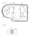
- Figs. 13-15 are exemplary circuit diagrams of various portions of the charging system 50 and illustrate various components used therein.
- Mechanical structures are also mounted on the circuit board 80.
- a pair of heat sinks 82 and 83 are mounted on the board 80 and are configured to remove heat from the electrical components.
- Each heat sink 82, 83 has a non-linear configuration to maximize the area of heat absorption surface.
- a fan 84 or the like is mounted onto heat sink 82.
- a slotted vent structure 85 may be provided on the heat sink 82 in alignment with the fan 84 to draw or push air across the heat sink 82 to enhance cooling.
- the housing 52 also has various vent slots 57.
- the charger contacts 72A and 72B and the communication contact 74 are each preferably mounted on the circuit board 80 via flexible mounts 73 such that when the top cover 51 is positioned relative to the bottom cover 53, the contacts 72A, 72B and 74 may flex and align with the appropriate areas within the opening 60.
- the circuit board 80 is supported on supports 85 within the bottom cover 53.
- the circuit board 80 preferably is not initially secured to the bottom cover 53 and is slightly adjustable relative thereto.
- the top cover 51 is placed onto the bottom cover 53, and feet 87 depending therefrom pass through holes 89 in the circuit board 80 such that the feet 87 engage the supports 85. Screws or the like are utilized to secure the feet 87 to the supports 85 and the circuit board 80 is maintained therebetween.
- the alignability of the circuit board 80 and the flexibility of the contacts 72A, 72B and 74 allows the charging system 50 to be easily assembled.
- the battery onboard circuit 20 and the microprocessor 90 communicate with one another to facilitate various charging functions as herein described.
- the various components utilized in carrying out these functions are illustrated in the various circuit diagrams in Figs. 11-15.
- the onboard circuit 20 preferably contains identifying indicia relating to the battery chemistry (i.e. NiCad vs. Lithium Ion), the battery voltage, the battery capacity and the like.
- This information is communicated to the microprocessor 90 to inform the charging system 50 the type of battery pack 10, 10' that has been placed in the charging system 50. The exchange of information occurs upon contact between the contacts 18 and 74.
- the onboard circuit 20 is independent of the stored charge within the battery pack 10, 10' and therefore the battery pack 10, 10' will be recognized by the charging system 50 even if the battery pack 10, 10' is completely drained.
- the onboard circuit 20 has stored in its memory a charging protocol specific to the battery pack 10, 10'.
- the onboard circuit 20 may be configured to store data related to the battery pack 10, 10', for example, a counter of the number of charges, a history of discharge and charge cycles, a history of battery renewing and the like.
- the microprocessor 90 can regulate the voltage output and the like such that the charging system 50 can charge batteries 10, 10' having different battery chemistries or having different voltages.
- the microprocessor 90 is preferably configured to receive and display the current charge level of the battery pack 10, 10'.
- the charging system 50 includes a charge level indicator 93 which may include a series of LEDs or the like.
- the microprocessor 90 is further configured to compare a current capacity of a battery pack 10, 10' to an original capacity of a battery pack 10, 10' (which is preferably stored in the memory of the onboard circuit 20) and, based thereon, recommend whether the battery pack 10, 10' should be renewed.
- a user depresses the renew button 95 to start a renewing cycle.
- the microprocessor 90 is configured to initiate a deep discharge of the battery pack 10, 10' and then recharge the battery pack 10, 10'.
- the discharge button 95 may be configured to light up upon detection of a condition in which a renew is recommend.
- the microprocessor may be configured to automatically renew the battery pack 10, 10' upon detection of such a condition.
Abstract
Description
- The present invention relates to cordless power tools, and more particularly, to batteries for cordless power tools and a charging system for charging such batteries.
- Cordless power tools are well-known and provide several advantages over traditional corded power tools. One of the advantages provided by cordless power tools is the mobility and/or portability when using the tool. For example, the operator of the cordless power tool can quickly and efficiently work over a larger area without having to continually adjust the power cord. Similarly, cordless power tools can be used in areas where electrical power is not available. Because of these advantages, the popularity of cordless power tools has increased among both professional and novice power tool users.
- It is desired to provide improved cordless power tool batteries and an improved charging system for such batteries.
- In one aspect, the invention may provide a cordless power tool battery including an onboard circuit configured to electronically communicate with an associated battery charging system. In one or more embodiments of the invention, the onboard circuit may contain identifying indicia relating to the battery chemistry, the battery voltage, the battery capacity and the like. In one or more embodiments of the invention, the onboard circuit may contain a charging protocol specific to the battery. In one or more embodiments of the invention, the onboard circuit may be configured to store data related to the battery, for example, a counter of the number of charges, a history of discharge and charge cycles, a history of battery renewing and the like. In one or more embodiments of the invention, the onboard circuit may be configured to communicate with the charging system even if the battery has no voltage.
- In another aspect, the invention may provide a cordless power tool battery charging system. In one or more embodiments of the invention, the charging system may be configured to accept multiple input voltages. In one or more embodiments of the invention, the charging system may be configured to charge batteries having different battery chemistries. In one or more embodiments of the invention, the charging system may be configured to charge batteries having different voltages. In one or more embodiments of the invention, the charging system may be configured to charge batteries in accordance with a charging protocol stored in the battery. In one or more embodiments of the invention, the charging system may be configured to display the current charge level of a battery. In one or more embodiments of the invention, the charging system may be configured to compare a current capacity of a battery to an original capacity of a battery and, based thereon, recommend whether the battery should be renewed. In one or more embodiments of the invention, the charging system may be configured to renew a battery by deep discharging the battery and then recharging the battery.
- In another aspect, the invention may provide a cordless power tool battery charging system configured to receive batteries having different housing configurations. In one or more embodiments of the invention, the charging system may include keyways configured to receive various battery key patterns. In one or more embodiments of the invention, the charging system may be configured such that the battery contacts and charging system contacts are disengaged prior to removal of the battery from the charging system. In one or more embodiments of the invention, the batteries may include an onboard circuit contact on a distal end surface thereof for contact with a corresponding contact in the charging system. In one or more embodiments of the invention, the charging system may include flexible battery contacts such that the battery contacts within the charging system housing. In one or more embodiments of the invention, the charging system may include a patterned heat sink extending therein. In one or more embodiments of the invention, the charging system may include a fan mounted on a heat sink and wherein the heat sink may further include through passages aligned with the fan.
-
- Fig. 1 is a perspective view of an exemplary Nickel Cadmium battery in accordance with a first embodiment of the present invention.
- Fig. 2 is a perspective view of an exemplary Lithium Ion battery in accordance with an alternate embodiment of the present invention.
- Fig. 3 is a top plan view of the battery of Fig. 2.
- Fig. 4 is a perspective view of a charging system in accordance with the present invention.
- Fig. 5 is a side elevation view of the charging system of Fig. 4.
- Fig. 6 is a top plan view of the charging system of Fig. 4.
- Fig. 7 is a top plan view similar to Fig. 6 illustrating the charging system of Fig. 4 with the housing top cover removed.
- Fig. 8 is a elevational view along the line 8-8 of Fig. 7.
- Fig. 9 is a top plan view of the charging system housing bottom cover.
- Fig. 10 is an elevation view illustrating the placement of the charging system housing top cover relative to the housing bottom cover.
- Fig. 11 is an exemplary circuit diagram of the battery of Fig. 1.
- Fig. 12 is an exemplary circuit diagram of the battery of Fig. 2.
- Fig. 13 is an exemplary circuit diagram of a buck circuit of the charging system of Fig. 4.
- Fig. 14 is an exemplary circuit diagram of a microprocessor and LED circuit of the charging system of Fig. 4.
- Fig. 15 is an exemplary circuit diagram of a flyback circuit of the charging system of Fig. 4.
- Although the invention is illustrated and described herein with reference to specific embodiments, the invention is not intended to be limited to the details shown. Rather, various modifications may be made in the details within the scope and range of equivalents of the claims and without departing from the invention.
- Referring to Figs. 1-3, two
exemplary battery packs 10, 10' of the present invention are shown. Thebattery pack 10 illustrated in Fig. 1 utilizes Nickel Cadmium battery cells while the battery pack 10' illustrated in Figs. 2 and 3 utilizes Lithium Ion battery cells. Exemplary circuit diagrams for bothbattery packs 10 and 10' are illustrated in Figs. 11 and 12, respectively. - Each
battery pack 10, 10' includes amain housing 12 with astem portion 14 extending therefrom. Themain housing 12 and thestem portion 14 house the battery cells (not shown). Thestem portion 14 preferably houses one or more of the battery cells. In each of the illustrated embodiments, thestem portion 14 has acylindrical body 13 extending from themain housing 12 to anend cap 15. A pair ofopposed openings 17 are provided in thebody 13 adjacent to theend cap 15. The number and position of theopenings 17 may be varied. Theopenings 17 are configured to expose the batteryelectrical contacts 16A and 16B which are electrically interconnected with the battery cells and thebattery communication contact 18 which is electrically interconnected with the batteryonboard circuit 20. - Referring to Figs. 1-3, each
battery pack 10 and 10' includesvarious support keys 22 andalignment keys 24 extending radially outward from thestem portion body 13. Thesupport keys 22 are configured to align with and rotatably engage support keyways in various portable tools. Thesupport keys 22 and thealignment keys 24 can be arranged in various configurations, including different widths, heights, positions, numbers and the like. In the preferred embodiment, the configuration of thesupport keys 22 andalignment key 24 are configured such that thebattery pack 10, 10' is properly aligned with the power tool orcharging system 50, as will be described hereinafter, such that the proper polarity of thecontacts 16A and 16B is maintained. - In the preferred embodiment, each
specific support key 22 andalignment key 24 configuration corresponds to abattery pack 10, 10' having a specific voltage such that thebattery pack 10, 10' is useable only in power tools requiring such voltage and having corresponding keyways to receive thebattery pack 10, 10'. Since the configuration of thekeys 22 and thealignment keyway 24 are distinct for each voltage, the different voltage battery packs would not be capable of inadvertent use with the wrong tool. - Referring to Figs. 4-10, a preferred embodiment of the
charging system 50 will be described. The chargingsystem 50 generally includes ahousing 52 comprising atop cover 51 and abottom cover 53. A batterystem receiving opening 60 is defined through thetop cover 51. Theopening 60 includes one or more supportkey keyways 62 and one or more alignmentkey keyways 64. Thekeyways pack support keys 22 andalignment keys 24, such that the chargingsystem 50 provides a universal charger for various battery voltages. For example, the supportkey keyways 62 are typically wider than most, if not all of thesupport keys 22, such that, relative to other voltage key configurations, thekeys 22 can be moved circumferentially and still align with thekeyways 62.Stops 66 are preferably provided within theopening 60 such that the battery pack stem 14 can only be rotated a given amount within theopening 60. - To further facilitate universal usage of the charging
system 50, the chargingsystem 50 preferably includes aplug port 65 with male pins 67 configured to mate with the female plug of cords (not shown) useable with different input voltages. As illustrated in the circuit diagrams, the male pins 67 are associated with a voltage converter which allows the charging system to be utilized with different input voltages. - Referring to Figs. 6 and 7, the charging
system 50 includes a pair of opposedelectrical contacts 72A and 72B configured to electrically connect with thebattery pack contacts 16A and 16B. Again, the configuration of thesupport keys 22 andalignment key 24 and thekeyways battery pack 10, 10' is properly aligned with the chargingsystem 50 such that the proper polarity of thecontacts 16A and 16B is maintained. - Each
electrical contact 16A, 16B preferably includes a radially taperedportion 19 extending to anarcuate portion 21. Thetapered portions 19 are configured to first contact thecharger contacts 72A and 72B during rotation of thebattery pack 10, 10' relative to the chargingsystem 50 such that thecharger contacts 72A, 72B ride along the taperedportions 19 and into final engagement with thearcuate portion 21. The taperedportion 19 may be made from conductive material, or alternatively, may be a non-conductive material. In the initially inserted position, prior to rotation into electrical contact, thebattery pack contacts 16A and 16B are circumferentially offset from and thereby disengaged from thecharger contacts 72A and 72B. As such, during axial movement of the battery pack stem 14 into theopening 60, thecontacts - A
communication contact 74 extends from the circuit board 80 within the chargingsystem 50 and is configured to engage thebattery communication contact 18. Electrical connection between thebattery communication contact 18 and thecommunication contact 74 provides a digital link between theonboard circuit 20 in thebattery pack 10, 10' and a microprocessor 90 or the like in the chargingsystem 50. An exemplaryonboard circuit 20 is the DS2438 manufactured by Dallas Semiconductor, the specifications of which are incorporated herein by reference. The functions of theonboard circuit 20 and the microprocessor 90 will be described hereinafter. - Referring to Figs. 11 and 12, exemplary circuit diagrams of the
batteries 10, 10' of Figs. 1 and 2, respectively, are shown. Each of thebatteries 10, 10' includes a plurality ofbattery cells 30, 30'. Thebattery cells 30, 30' are connected with thebattery contacts 16A and 16B and are also connected with theonboard circuit 20. Avoltage regulator 32, which shuts down the battery when an over discharge is detected, is preferably provided in the battery circuit. Asuitable voltage regulator 32 is a model number LM9036-3.3 available from National Semiconductor. Eachbattery 10, 10' includes a communication link between theonboard circuit 20 and thebattery communication contact 18. In the battery circuit of Fig. 12, avoltage sensor 36 is also provided to prevent over discharging. Asuitable voltage sensor 36 is a model number S-8242AAMB6T1GZ available from Seiko Instruments. The battery circuit of Fig. 12 also includes amicroprocessor 34 which controls operation of the battery 10'. A suitable microprocessor is a model number UPD78F9212GR available from NEC Electronics. A series of fuel gauge lights 38 are connected to themicroprocessor 34 and may be actuated using apush button 39 or the like to show the current fuel level directly on the battery 10'. The battery circuit of Fig. 12 also includes a current sense resistor 31 and aMOFSET switch 33 which facilitates disabling of power in the battery 10'. A suitable MOFSET switch is a model number NP88N03KDG available from NEC Electronics. - Referring to Fig. 7, the various components of the charging
system 50 are mounted on a circuit board 80. Figs. 13-15 are exemplary circuit diagrams of various portions of the chargingsystem 50 and illustrate various components used therein. Mechanical structures are also mounted on the circuit board 80. A pair ofheat sinks heat sink fan 84 or the like is mounted ontoheat sink 82. Referring to Fig. 8, a slottedvent structure 85 may be provided on theheat sink 82 in alignment with thefan 84 to draw or push air across theheat sink 82 to enhance cooling. Thehousing 52 also hasvarious vent slots 57. - The
charger contacts 72A and 72B and thecommunication contact 74 are each preferably mounted on the circuit board 80 viaflexible mounts 73 such that when thetop cover 51 is positioned relative to thebottom cover 53, thecontacts opening 60. Referring to Figs. 7, 9 and 10, in the preferred embodiment, the circuit board 80 is supported onsupports 85 within thebottom cover 53. The circuit board 80 preferably is not initially secured to thebottom cover 53 and is slightly adjustable relative thereto. Thetop cover 51 is placed onto thebottom cover 53, andfeet 87 depending therefrom pass throughholes 89 in the circuit board 80 such that thefeet 87 engage thesupports 85. Screws or the like are utilized to secure thefeet 87 to thesupports 85 and the circuit board 80 is maintained therebetween. The alignability of the circuit board 80 and the flexibility of thecontacts system 50 to be easily assembled. - The battery
onboard circuit 20 and the microprocessor 90 communicate with one another to facilitate various charging functions as herein described. The various components utilized in carrying out these functions are illustrated in the various circuit diagrams in Figs. 11-15. For example, theonboard circuit 20 preferably contains identifying indicia relating to the battery chemistry (i.e. NiCad vs. Lithium Ion), the battery voltage, the battery capacity and the like. This information is communicated to the microprocessor 90 to inform thecharging system 50 the type ofbattery pack 10, 10' that has been placed in the chargingsystem 50. The exchange of information occurs upon contact between thecontacts onboard circuit 20 is independent of the stored charge within thebattery pack 10, 10' and therefore thebattery pack 10, 10' will be recognized by the chargingsystem 50 even if thebattery pack 10, 10' is completely drained. In the preferred embodiment, theonboard circuit 20 has stored in its memory a charging protocol specific to thebattery pack 10, 10'. In another aspect of the invention, theonboard circuit 20 may be configured to store data related to thebattery pack 10, 10', for example, a counter of the number of charges, a history of discharge and charge cycles, a history of battery renewing and the like. - Since the battery
onboard circuit 20 provides the microprocessor 90 with specific information relating to thebattery pack 10, 10', preferably including the charging protocol, the microprocessor 90 can regulate the voltage output and the like such that the chargingsystem 50 can chargebatteries 10, 10' having different battery chemistries or having different voltages. The microprocessor 90 is preferably configured to receive and display the current charge level of thebattery pack 10, 10'. In this regard, the chargingsystem 50 includes acharge level indicator 93 which may include a series of LEDs or the like. In the preferred embodiment, the microprocessor 90 is further configured to compare a current capacity of abattery pack 10, 10' to an original capacity of abattery pack 10, 10' (which is preferably stored in the memory of the onboard circuit 20) and, based thereon, recommend whether thebattery pack 10, 10' should be renewed. To renew thebattery pack 10, 10', a user depresses the renewbutton 95 to start a renewing cycle. Upon depression of the renewbutton 95, the microprocessor 90 is configured to initiate a deep discharge of thebattery pack 10, 10' and then recharge thebattery pack 10, 10'. Thedischarge button 95 may be configured to light up upon detection of a condition in which a renew is recommend. Alternatively, the microprocessor may be configured to automatically renew thebattery pack 10, 10' upon detection of such a condition. - While preferred embodiments of the invention have been shown and described herein, it will be understood that such embodiments are provided by way of example only. Numerous variations, changes and substitutions will occur to those skilled in the art without departing from the spirit of the invention. Accordingly, it is intended that the appended claims cover all such variations as fall within the spirit and scope of the invention.
Claims (21)
- A cordless power tool battery charging system comprising:a charger housing having a battery receiving opening; anda charging circuit configured to charge a battery engaged within the battery receiving opening, the charging circuit configured to charge in accordance with various charging protocols in dependence on the battery engaged within the battery receiving opening.
- A cordless power tool battery charging system according to claim 1 further comprising a voltage converter such that the charging system is configured for connection to at least two different input voltage sources.
- A cordless power tool battery charging system according to any of the preceding claims wherein the charging protocol is based on the battery chemistry, the battery voltage, or a combination thereof.
- A cordless power tool battery charging system according to any of the preceding claims wherein the charging system is configured to charge the battery in accordance with a charging protocol stored in the battery.
- A cordless power tool battery charging system according to any of the preceding claims wherein the charging system is configured to display a present charge level of an engaged battery.
- A cordless power tool battery charging system according to any of the preceding claims wherein the charging system is configured to compare a current capacity of an engaged battery to an original capacity of the battery and, based thereon, recommend whether the battery should be renewed.
- A cordless power tool battery charging system according to any of the preceding claims wherein the charging system is configured to renew the engaged battery by deep discharging the battery and then recharging the battery.
- A cordless power tool battery charging system according to the preceding claim wherein the charging system is configured to automatically renew an engaged battery upon detection of a renew condition wherein a current capacity of the engaged battery is below a predetermined threshold compared to an original capacity of the battery.
- A cordless power tool battery charging system according to any of the preceding claims wherein the battery receiving opening is configured to receive batteries having different housing configurations.
- A cordless power tool battery charging system according to any of the preceding claims wherein the battery receiving opening has at least one keyway configured to receive at least two distinct battery key patterns.
- A cordless power tool battery charging system according to any of the preceding claims wherein the battery receiving opening has at least one charging system contact therein and the opening is configured such that a battery may be fully received within the battery receiving opening without contacting the at least one charging system contact, the battery requiring a secondary motion to engage a battery contact with the corresponding charging system contact.
- A cordless power tool battery charging system according to any of the preceding claims further comprising a patterned heat sink extending about a portion of the charging circuit.
- A cordless power tool battery charging system according to the preceding claim wherein a fan is mounted on the heat sink and the heat sink includes through passages aligned with the fan.
- A cordless power tool battery and charging system assembly comprising:a cordless tool battery comprising:at least one battery cell;an onboard circuit configured to store battery information;a battery communication contact; anda charging system comprising:a charger housing having a battery receiving opening configured to receive a portion of the cordless tool battery;a communication contact within the battery receiving opening configured to engage the battery communication contact; anda charging circuit configured to receive battery information through the engagement of the battery communication contact and the communication contact, the charging circuit configured to charge in accordance with various charging protocols in dependence on the received battery information.
- A cordless power tool battery comprising:at least one battery cell; andan onboard circuit configured to electronically communicate with an associated battery charging system.
- A cordless power tool battery according to the preceding claim wherein the onboard circuit stores identifying indicia of the battery.
- A cordless power tool battery according to the preceding claim wherein the identifying indicia relates to a chemistry of the at least one battery cell, a voltage of the battery, a capacity of the battery or a combination thereof.
- A cordless power tool battery according to any of the two preceding claims wherein the identifying indicia is stored in a permanent memory.
- A cordless power tool battery according to any of the three preceding claims wherein the onboard circuit stores a charging protocol specific to the battery.
- A cordless power tool battery according to any of the four preceding claims wherein the onboard circuit is configured to store data related to the battery.
- A cordless power tool battery according to the preceding claim wherein the stored data includes a counter of the number of charges, a history of discharge and charge cycles, a history of battery renewing, or a combination thereof.
Applications Claiming Priority (2)
| Application Number | Priority Date | Filing Date | Title |
|---|---|---|---|
| US80995506P | 2006-05-31 | 2006-05-31 | |
| EP07109337.1A EP1863108B1 (en) | 2006-05-31 | 2007-05-31 | Cordless power tool battery and charging system therefore |
Related Parent Applications (2)
| Application Number | Title | Priority Date | Filing Date |
|---|---|---|---|
| EP07109337.1A Division EP1863108B1 (en) | 2006-05-31 | 2007-05-31 | Cordless power tool battery and charging system therefore |
| EP07109337.1 Division | 2007-05-31 |
Publications (3)
| Publication Number | Publication Date |
|---|---|
| EP1906470A2 true EP1906470A2 (en) | 2008-04-02 |
| EP1906470A3 EP1906470A3 (en) | 2008-10-08 |
| EP1906470B1 EP1906470B1 (en) | 2011-12-14 |
Family
ID=39126566
Family Applications (1)
| Application Number | Title | Priority Date | Filing Date |
|---|---|---|---|
| EP07120111A Expired - Fee Related EP1906470B1 (en) | 2006-05-31 | 2007-05-31 | Cordless power tool battery charging system |
Country Status (1)
| Country | Link |
|---|---|
| EP (1) | EP1906470B1 (en) |
Cited By (1)
| Publication number | Priority date | Publication date | Assignee | Title |
|---|---|---|---|---|
| EP1916069A2 (en) * | 2006-10-27 | 2008-04-30 | William M. Ball, Jr. | Cordless power tool battery charging and analyzing system |
Citations (7)
| Publication number | Priority date | Publication date | Assignee | Title |
|---|---|---|---|---|
| DE3340882C1 (en) | 1983-11-11 | 1985-06-27 | Messerschmitt-Bölkow-Blohm GmbH, 8012 Ottobrunn | Device for temperature monitoring and reconditioning of batteries consisting of electrochemical individual cells |
| US5144217A (en) | 1989-03-03 | 1992-09-01 | Black & Decker Inc. | Cordless tool battery housing and charging system |
| DE4225088A1 (en) | 1991-07-31 | 1993-02-04 | Sanyo Electric Co | Battery discharging equipment with voltage measurement - has timer starting discharge at defined period after battery voltage falls below threshold |
| EP0944153A2 (en) | 1998-03-18 | 1999-09-22 | Makita Corporation | Power tool charging system having a charge level indicator and charge control functions |
| US6075341A (en) | 1999-02-17 | 2000-06-13 | Black & Decker Inc. | Power pack charging system for a power tool |
| EP1128517A2 (en) | 2000-02-24 | 2001-08-29 | Makita Corporation | Adapters for rechargeable battery packs |
| WO2006044693A2 (en) | 2004-10-18 | 2006-04-27 | Black & Decker Inc. | Cordless power system |
-
2007
- 2007-05-31 EP EP07120111A patent/EP1906470B1/en not_active Expired - Fee Related
Patent Citations (7)
| Publication number | Priority date | Publication date | Assignee | Title |
|---|---|---|---|---|
| DE3340882C1 (en) | 1983-11-11 | 1985-06-27 | Messerschmitt-Bölkow-Blohm GmbH, 8012 Ottobrunn | Device for temperature monitoring and reconditioning of batteries consisting of electrochemical individual cells |
| US5144217A (en) | 1989-03-03 | 1992-09-01 | Black & Decker Inc. | Cordless tool battery housing and charging system |
| DE4225088A1 (en) | 1991-07-31 | 1993-02-04 | Sanyo Electric Co | Battery discharging equipment with voltage measurement - has timer starting discharge at defined period after battery voltage falls below threshold |
| EP0944153A2 (en) | 1998-03-18 | 1999-09-22 | Makita Corporation | Power tool charging system having a charge level indicator and charge control functions |
| US6075341A (en) | 1999-02-17 | 2000-06-13 | Black & Decker Inc. | Power pack charging system for a power tool |
| EP1128517A2 (en) | 2000-02-24 | 2001-08-29 | Makita Corporation | Adapters for rechargeable battery packs |
| WO2006044693A2 (en) | 2004-10-18 | 2006-04-27 | Black & Decker Inc. | Cordless power system |
Cited By (2)
| Publication number | Priority date | Publication date | Assignee | Title |
|---|---|---|---|---|
| EP1916069A2 (en) * | 2006-10-27 | 2008-04-30 | William M. Ball, Jr. | Cordless power tool battery charging and analyzing system |
| EP1916069A3 (en) * | 2006-10-27 | 2010-09-22 | Ingersoll-Rand Company | Cordless power tool battery charging and analyzing system |
Also Published As
| Publication number | Publication date |
|---|---|
| EP1906470A3 (en) | 2008-10-08 |
| EP1906470B1 (en) | 2011-12-14 |
Similar Documents
| Publication | Publication Date | Title |
|---|---|---|
| US7863857B2 (en) | Cordless power tool battery and charging system therefore | |
| EP1916069A2 (en) | Cordless power tool battery charging and analyzing system | |
| US6441589B1 (en) | Portable battery recharge station | |
| CN106232301B (en) | Improvements in portable power supplies | |
| US8450971B2 (en) | Lithium-based battery pack for a hand held power tool | |
| JP4547036B2 (en) | Battery pack | |
| US20180198292A1 (en) | Universal Power Tool Battery Pack And Recharging System | |
| KR960006135B1 (en) | Battery powered device | |
| US7365514B2 (en) | Battery charger | |
| US20160372939A1 (en) | Power Tool System | |
| CN217607501U (en) | Charger adapted to charge either of first battery pack and second battery pack, and kit | |
| EP1906470B1 (en) | Cordless power tool battery charging system | |
| EP3582933A1 (en) | Power and home tools | |
| AU2020102987A4 (en) | Battery charger for multiple battery packs | |
| JP2005045989A (en) | Charger for portable electronic apparatus | |
| JP3130892U (en) | Charging system | |
| EP0779693A1 (en) | A charging battery structure for hand phone | |
| JPH07282854A (en) | Charging device for secondary battery and secondary battery |
Legal Events
| Date | Code | Title | Description |
|---|---|---|---|
| PUAI | Public reference made under article 153(3) epc to a published international application that has entered the european phase |
Free format text: ORIGINAL CODE: 0009012 |
|
| PUAL | Search report despatched |
Free format text: ORIGINAL CODE: 0009013 |
|
| AC | Divisional application: reference to earlier application |
Ref document number: 1863108 Country of ref document: EP Kind code of ref document: P |
|
| AK | Designated contracting states |
Kind code of ref document: A2 Designated state(s): AT BE BG CH CY CZ DE DK EE ES FI FR GB GR HU IE IS IT LI LT LU LV MC MT NL PL PT RO SE SI SK TR |
|
| AX | Request for extension of the european patent |
Extension state: AL BA HR MK YU |
|
| AK | Designated contracting states |
Kind code of ref document: A3 Designated state(s): AT BE BG CH CY CZ DE DK EE ES FI FR GB GR HU IE IS IT LI LT LU LV MC MT NL PL PT RO SE SI SK TR |
|
| AX | Request for extension of the european patent |
Extension state: AL BA HR MK RS |
|
| PUAF | Information related to the publication of a search report (a3 document) modified or deleted |
Free format text: ORIGINAL CODE: 0009199SEPU |
|
| D17D | Deferred search report published (deleted) | ||
| PUAL | Search report despatched |
Free format text: ORIGINAL CODE: 0009013 |
|
| AK | Designated contracting states |
Kind code of ref document: A3 Designated state(s): AT BE BG CH CY CZ DE DK EE ES FI FR GB GR HU IE IS IT LI LT LU LV MC MT NL PL PT RO SE SI SK TR |
|
| AX | Request for extension of the european patent |
Extension state: AL BA HR MK RS |
|
| 17P | Request for examination filed |
Effective date: 20080930 |
|
| 17Q | First examination report despatched |
Effective date: 20081126 |
|
| AKX | Designation fees paid |
Designated state(s): DE FR GB IT SE |
|
| GRAP | Despatch of communication of intention to grant a patent |
Free format text: ORIGINAL CODE: EPIDOSNIGR1 |
|
| RTI1 | Title (correction) |
Free format text: CORDLESS POWER TOOL BATTERY CHARGING SYSTEM |
|
| GRAS | Grant fee paid |
Free format text: ORIGINAL CODE: EPIDOSNIGR3 |
|
| GRAA | (expected) grant |
Free format text: ORIGINAL CODE: 0009210 |
|
| AC | Divisional application: reference to earlier application |
Ref document number: 1863108 Country of ref document: EP Kind code of ref document: P |
|
| AK | Designated contracting states |
Kind code of ref document: B1 Designated state(s): DE FR GB IT SE |
|
| REG | Reference to a national code |
Ref country code: GB Ref legal event code: FG4D |
|
| REG | Reference to a national code |
Ref country code: DE Ref legal event code: R096 Ref document number: 602007019298 Country of ref document: DE Effective date: 20120216 |
|
| PG25 | Lapsed in a contracting state [announced via postgrant information from national office to epo] |
Ref country code: SE Free format text: LAPSE BECAUSE OF FAILURE TO SUBMIT A TRANSLATION OF THE DESCRIPTION OR TO PAY THE FEE WITHIN THE PRESCRIBED TIME-LIMIT Effective date: 20111214 |
|
| PLBE | No opposition filed within time limit |
Free format text: ORIGINAL CODE: 0009261 |
|
| STAA | Information on the status of an ep patent application or granted ep patent |
Free format text: STATUS: NO OPPOSITION FILED WITHIN TIME LIMIT |
|
| 26N | No opposition filed |
Effective date: 20120917 |
|
| REG | Reference to a national code |
Ref country code: DE Ref legal event code: R097 Ref document number: 602007019298 Country of ref document: DE Effective date: 20120917 |
|
| REG | Reference to a national code |
Ref country code: FR Ref legal event code: PLFP Year of fee payment: 10 |
|
| REG | Reference to a national code |
Ref country code: FR Ref legal event code: PLFP Year of fee payment: 11 |
|
| REG | Reference to a national code |
Ref country code: DE Ref legal event code: R082 Ref document number: 602007019298 Country of ref document: DE Representative=s name: HASELTINE LAKE KEMPNER LLP, DE Ref country code: DE Ref legal event code: R082 Ref document number: 602007019298 Country of ref document: DE Representative=s name: HL KEMPNER PATENTANWALT, RECHTSANWALT, SOLICIT, DE Ref country code: DE Ref legal event code: R082 Ref document number: 602007019298 Country of ref document: DE Representative=s name: MURGITROYD & COMPANY, DE Ref country code: DE Ref legal event code: R082 Ref document number: 602007019298 Country of ref document: DE Representative=s name: HASELTINE LAKE LLP, DE |
|
| REG | Reference to a national code |
Ref country code: FR Ref legal event code: PLFP Year of fee payment: 12 |
|
| PGFP | Annual fee paid to national office [announced via postgrant information from national office to epo] |
Ref country code: DE Payment date: 20200421 Year of fee payment: 14 Ref country code: FR Payment date: 20200421 Year of fee payment: 14 |
|
| PGFP | Annual fee paid to national office [announced via postgrant information from national office to epo] |
Ref country code: IT Payment date: 20200421 Year of fee payment: 14 Ref country code: GB Payment date: 20200423 Year of fee payment: 14 |
|
| REG | Reference to a national code |
Ref country code: GB Ref legal event code: 732E Free format text: REGISTERED BETWEEN 20200806 AND 20200812 |
|
| REG | Reference to a national code |
Ref country code: DE Ref legal event code: R082 Ref document number: 602007019298 Country of ref document: DE Representative=s name: HASELTINE LAKE KEMPNER LLP, DE Ref country code: DE Ref legal event code: R081 Ref document number: 602007019298 Country of ref document: DE Owner name: INGERSOLL-RAND INDUSTRIAL U.S., INC. (N.D.GES., US Free format text: FORMER OWNER: INGERSOLL-RAND COMPANY, MONTVALE, N.J., US Ref country code: DE Ref legal event code: R082 Ref document number: 602007019298 Country of ref document: DE Representative=s name: HL KEMPNER PATENTANWALT, RECHTSANWALT, SOLICIT, DE Ref country code: DE Ref legal event code: R082 Ref document number: 602007019298 Country of ref document: DE Representative=s name: MURGITROYD & COMPANY, DE |
|
| REG | Reference to a national code |
Ref country code: DE Ref legal event code: R079 Ref document number: 602007019298 Country of ref document: DE Free format text: PREVIOUS MAIN CLASS: H01M0002100000 Ipc: H01M0050200000 |
|
| REG | Reference to a national code |
Ref country code: DE Ref legal event code: R082 Ref document number: 602007019298 Country of ref document: DE Representative=s name: HL KEMPNER PATENTANWALT, RECHTSANWALT, SOLICIT, DE Ref country code: DE Ref legal event code: R082 Ref document number: 602007019298 Country of ref document: DE Representative=s name: MURGITROYD & COMPANY, DE |
|
| REG | Reference to a national code |
Ref country code: DE Ref legal event code: R082 Ref document number: 602007019298 Country of ref document: DE Representative=s name: MURGITROYD & COMPANY, DE |
|
| REG | Reference to a national code |
Ref country code: DE Ref legal event code: R119 Ref document number: 602007019298 Country of ref document: DE |
|
| GBPC | Gb: european patent ceased through non-payment of renewal fee |
Effective date: 20210531 |
|
| PG25 | Lapsed in a contracting state [announced via postgrant information from national office to epo] |
Ref country code: GB Free format text: LAPSE BECAUSE OF NON-PAYMENT OF DUE FEES Effective date: 20210531 Ref country code: DE Free format text: LAPSE BECAUSE OF NON-PAYMENT OF DUE FEES Effective date: 20211201 |
|
| PG25 | Lapsed in a contracting state [announced via postgrant information from national office to epo] |
Ref country code: FR Free format text: LAPSE BECAUSE OF NON-PAYMENT OF DUE FEES Effective date: 20210531 |
|
| PG25 | Lapsed in a contracting state [announced via postgrant information from national office to epo] |
Ref country code: IT Free format text: LAPSE BECAUSE OF NON-PAYMENT OF DUE FEES Effective date: 20200531 |