EP1906488A2 - A dual band antenna for millimeter wave synthetic vision systems - Google Patents
A dual band antenna for millimeter wave synthetic vision systems Download PDFInfo
- Publication number
- EP1906488A2 EP1906488A2 EP20070117096 EP07117096A EP1906488A2 EP 1906488 A2 EP1906488 A2 EP 1906488A2 EP 20070117096 EP20070117096 EP 20070117096 EP 07117096 A EP07117096 A EP 07117096A EP 1906488 A2 EP1906488 A2 EP 1906488A2
- Authority
- EP
- European Patent Office
- Prior art keywords
- antenna
- slotted waveguide
- slots
- microstrip patch
- patch array
- Prior art date
- Legal status (The legal status is an assumption and is not a legal conclusion. Google has not performed a legal analysis and makes no representation as to the accuracy of the status listed.)
- Granted
Links
Images


Classifications
-
- H—ELECTRICITY
- H01—ELECTRIC ELEMENTS
- H01Q—ANTENNAS, i.e. RADIO AERIALS
- H01Q21/00—Antenna arrays or systems
- H01Q21/0006—Particular feeding systems
- H01Q21/0037—Particular feeding systems linear waveguide fed arrays
- H01Q21/0043—Slotted waveguides
- H01Q21/005—Slotted waveguides arrays
-
- H—ELECTRICITY
- H01—ELECTRIC ELEMENTS
- H01Q—ANTENNAS, i.e. RADIO AERIALS
- H01Q1/00—Details of, or arrangements associated with, antennas
- H01Q1/27—Adaptation for use in or on movable bodies
- H01Q1/28—Adaptation for use in or on aircraft, missiles, satellites, or balloons
-
- H—ELECTRICITY
- H01—ELECTRIC ELEMENTS
- H01Q—ANTENNAS, i.e. RADIO AERIALS
- H01Q21/00—Antenna arrays or systems
- H01Q21/06—Arrays of individually energised antenna units similarly polarised and spaced apart
- H01Q21/061—Two dimensional planar arrays
- H01Q21/065—Patch antenna array
-
- H—ELECTRICITY
- H01—ELECTRIC ELEMENTS
- H01Q—ANTENNAS, i.e. RADIO AERIALS
- H01Q21/00—Antenna arrays or systems
- H01Q21/28—Combinations of substantially independent non-interacting antenna units or systems
-
- H—ELECTRICITY
- H01—ELECTRIC ELEMENTS
- H01Q—ANTENNAS, i.e. RADIO AERIALS
- H01Q25/00—Antennas or antenna systems providing at least two radiating patterns
- H01Q25/002—Antennas or antenna systems providing at least two radiating patterns providing at least two patterns of different beamwidth; Variable beamwidth antennas
Definitions
- Aircraft include a weather antenna, such as an X-band slotted waveguide antenna, that is used during take off and landing to predict the presence of windshear in front of the aircraft.
- the X-band slotted waveguide antenna emits radiation into a relatively large azimuthal angle.
- Millimeter wave (MMW) synthetic or enhanced vision systems for civil aviation are effective systems to provide visibility of objects located in fog, smoke, dust and other obscurants. Such synthetic vision systems would be useful if implemented to assist aircraft as it lands in areas that are foggy, smoky, dusty, or otherwise obscured.
- the millimeter wave antenna is generated by a microstrip antenna and emits radiation into a narrow beam azimuth angle that is appropriate for viewing the landing strip from a distance during take off and landing of an aircraft.
- the cost of adding an additional antenna system to an aircraft makes an implementation of both an X-band slotted waveguide antenna and a dedicated MMW scanning antenna unlikely.
- the additional weight from a second antenna system reduces fuel efficiency of the aircraft and the range of the aircraft.
- a first aspect of the present invention includes a dual band antenna system for synthetic vision systems including a slotted waveguide antenna having rows of slots on a front surface, a microstrip patch array antenna overlying the front surface of the slotted waveguide antenna; and at least one transceiver communicatively coupled to at least one of the slotted waveguide antenna and the microstrip patch array antenna.
- Figure 1 shows one embodiment of a dual band antenna system for synthetic vision systems in a radome of an aircraft in accordance with the present invention.
- Figure 2 shows an oblique view of one embodiment of a dual band antenna and communicatively coupled transceivers in accordance with the present invention.
- Figure 3 shows a side cross-sectional view of one embodiment of a dual band antenna in accordance with the present invention.
- Figure 4 shows a side cross-sectional view of one embodiment of an enlarged portion of a dual band antenna in accordance with the present invention.
- Figure 5 shows a side cross-sectional view of one embodiment of an enlarged portion of a dual band antenna in accordance with the present invention.
- Figure 6 shows an oblique view of one embodiment of a dual band antenna and communicatively coupled transceivers in accordance with the present invention.
- Figure 7 is a block diagram of one embodiment of a dual band antenna that is rotatable in accordance with the present invention.
- Figure 8 is a flow diagram of one embodiment of a method to provide broadband synthetic vision in accordance with the present invention
- Figure 9 shows an elevation view of one embodiment of a dual band antenna emitting and receiving electro-magnetic radiation in accordance with the present invention.
- Figure 10 shows a plan view of one embodiment of the dual band antenna emitting and receiving electro-magnetic radiation in accordance with the present invention.
- FIG 1 shows one embodiment of a dual band antenna system for synthetic vision systems 20 in a radome 17 of an aircraft 15 in accordance with the present invention.
- the shown radome 17 is at the front or "nose" of the aircraft 15. Only a front section 16 of the aircraft 15 is shown in Figure 1.
- the dual band antenna system for synthetic vision systems 20, also referred to here as “dual band antenna system 20,” includes a dual band antenna represented generally by the numeral 23 that is fed by at least one transceiver (not visible in Figure 1) and mounted on at least one rotational stage (not visible in Figure 1) in the pedestal 55.
- the dual band antenna 23, also referred to herein as "source 23,” includes a slotted waveguide antenna 40 and a microstrip patch array antenna (not visible in Figure 1).
- the slotted waveguide antenna 40 sends and receives signals via a slotted waveguide feedline 82.
- the dual band antenna system 20 is communicatively coupled to display 30.
- the display 30 includes a processor 32 and a screen 33, which displays an image of a runway represented generally by the numeral 34.
- the dual band antenna system 20 generates signals that provide information indicative of the images of the runway 34.
- the processor 32 receives the signals from the dual band antenna system 20 and processes the signals in order to display the image of the runway 34 on the screen 33 for viewing by a user of the aircraft 15.
- FIG. 2 shows an oblique view of one embodiment of a dual band antenna 21 and communicatively coupled transceivers 80 and 85 in accordance with the present invention.
- the dual band antenna 21 is also referred to herein as "source 21.”
- the microstrip patch array antenna represented generally by the numeral 60 overlays the front surface 41 of the slotted waveguide antenna represented generally by the numeral 40.
- the millimeter wave (MMW) transceiver 85 is communicatively coupled to the microstrip patch array antenna 60.
- the X-band transceiver 80 is communicatively coupled to the slotted waveguide antenna 40.
- the slotted waveguide antenna 40 has a width W and a length L.
- the width W of the slotted waveguide antenna 40 varies along the length L.
- the edge of slotted waveguide antenna 40 is approximately circular as shown in Figure 1.
- the slotted waveguide antenna 40 has rows of slots represented generally by the numerals 42, 45, and 46.
- the rows of slots 42, 45, and 46 extend parallel to the width edge along the width W of the slotted waveguide antenna 40.
- the walls 50 and/or 51 that are visible along the length edge of the slotted waveguide antenna 40 form cavities that extend under the rows of slots 42, 45, and 46.
- the rows of slots 45 have four slots represented generally by the numeral 48 on a front surface 41.
- the rows of slots 46 alternate with the rows of slots 45 and have three slots 48 on the front surface 41.
- the single row of slots 42 has four slots represented generally by the numeral 47 on the front surface 41 that lie under the microstrip patch array antenna 60 and that alternate with the rows of slots 46.
- the row of slots 42 in the slotted waveguide antenna 40 is also referred to herein as "subset 42" of the rows of slots 42, 45, and 46.
- the slots 48 in the rows of slots 46 are staggered in relation to the slots 48 in the rows of slots 45.
- the slots 47 in the row of slots 42 are staggered in relation to the slots 48 in the rows of slots 46.
- the period of slots 47 and 48 and the shape of slots 47 and 48 determine the resonant operating frequency of the electro-magnetic radiation.
- the overall size of the antenna 40 determines the beamwidth of the electro-magnetic radiation that is received and transmitted by the slotted waveguide antenna 40.
- Other configurations of the rows of slots 42, 45, and 46 are possible.
- the arrangement of the slots is determined by complex requirements including how much power is radiated from each area of the antenna, impedance matching, beamshape and sidelobe levels. There are well known design rules that constrain the arrangements of the slots that must be followed to make a usable antenna.
- the period and shapes of slots 47 and 48 are based on standard design methods known to those skilled in the art.
- the microstrip patch array antenna 40 includes a ground plane 67, at least one row of microstrips represented generally by the numeral 65 and at least one dielectric layer 68.
- the row of microstrips 65 comprises microstrips 66 formed from a periodically patterned array of metal or conductive material that overlays the top surface 69 of the dielectric layer 68 of microstrip patch array antenna 60.
- the periodically patterned array of microstrips 66 includes more columns than rows.
- the slots 47 in the slotted waveguide antenna 40 that are overlaid by the microstrip patch array antenna 60 are positioned parallel to the rows of microstrips 65 and on the opposite side of the ground plane 67 from the rows of microstrips 65.
- the row 42 is in the middle of the length of the slotted waveguide antenna 40.
- the dual band antenna 21 includes more than one row 42 that is overlaid by the microstrip patch array antenna 60.
- the slotted waveguide antenna 40 is an X-band weather radar slotted waveguide antenna and a microstrip patch array antenna 60 is a millimeter wave microstrip patch array antenna.
- the slotted waveguide antenna must emit frequency at a lower frequency (typically 2-3 or more times lower in frequency) than the microstrip antenna array to maintain the relationship between patch elements and the slots.
- the acceptable ratios of frequency for the combined the slotted and microstrip antennas can be determined as is understandable based on the teaching of the present application and knowledge of the art.
- the slotted waveguide antenna 40 end fed slotted waveguide antenna in which the waveguide structure that feeds the slotted waveguide antenna 40 runs down the edge of the slotted waveguide antenna 40.
- Figure 3 shows a side cross-sectional view of one embodiment of the dual band antenna 21 in accordance with the present invention.
- the plane upon which the cross-section view of Figure 3 is taken is indicated by section line 3-3 in Figure 2.
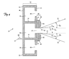
- Figure 4 shows a side cross-sectional view of one embodiment of an enlarged portion 22 of the dual band antenna 21 in accordance with the present invention.
- the portion 22 shown in Figure 4 is an enlarged view of the interface between the slotted waveguide antenna 40 and the microstrip patch array antenna 60.
- Cavities 53 are defined by neighboring walls 50, the front surface 41, and the back surface 44.
- Cavity 54 is defined by neighboring walls 51, the front surface 41, and the back surface 44.
- Cavities 56 are defined by wall 51 that is shared with cavity 54, wall 50 shared by cavity 53, the front surface 41, and the back surface 44.
- the cavities 53, 54 and 56 extend the complete width W ( Figure 2) of the slotted waveguide antenna 40.
- the slots 48 are periodic openings in the front surface 41 of cavities 53 and 56.
- the slots 47 are openings in the front surface 41 of cavity 54, which underlies the microstrip patch array antenna 60. In one implementation of this embodiment, the microstrip patch array antenna 60 overlays more than one cavity 54.
- the dielectric layer 68 separates the micro-strips 66 from the ground plane 67.
- the ground plane 67 overlays the front surface 41 of the cavity 54 the slotted waveguide antenna 40.
- the microstrip patch array antenna 65 is modified in regions 52 overlying the slots 47 in the subset 42 of rows of slots 42, 45 and 46 in the slotted waveguide antenna 40. Specifically, the ground plane 67 and the at least one dielectric layer 68 of microstrip patch array antenna are removed in regions 52 overlying slots 47 in the subset 42 of rows of slots 42, 45 and 46 in the slotted waveguide antenna 40 of dual band antenna 21.
- a coax cable 90 ( Figure 4) is communicatively coupled to feed millimeter wave signals between the millimeter wave transceiver 85 ( Figure 2) and the microstrip patch array antenna 60.
- the coax cable 90 is a micro-cable that passes through at least one wall 51 of the slotted waveguide antenna 40.
- Arrows 70 in Figure 4 indicate the extent of the electro-magnetic radiation that is emitted from the slotted waveguide antenna 40.
- the angle ⁇ V is the vertical beamwidth of the slotted waveguide antenna 40.
- Arrows 72 in Figure 4 indicate the extent of the electro-magnetic radiation that is emitted from the microstrip patch array antenna 60.
- the angle ⁇ V is the vertical beamwidth of the microstrip patch array antenna 60
- Figure 5 shows a side cross-sectional view of one embodiment of an enlarged portion 25 of a dual band antenna in accordance with the present invention.
- the portion 25 of Figure 5 differs from the portion 22 of Figure 4 in that the dielectric layer 68 is not removed from the regions 52 overlying slots 47 in the subset 42 of rows of slots 42, 45 and 46 in the slotted waveguide antenna 40.
- the portion of the dielectric layer 68 that is not removed from the regions 52 overlying slots 47 in the slotted waveguide antenna 40 is used to tune the dual band antenna 21.
- the microstrip patch array antenna 60 is modified by only removing the ground plane 67 in the regions 52 overlying slots 47 in the subset 42 of rows of slots 42, 45 and 46 in the slotted waveguide antenna 40.
- the electro-magnetic radiation is able to radiate through the dielectric layer 68.
- the dual band antenna 21 ( Figure 2) includes either portion 22 of Figure 4 or portion 25 of Figure 5.
- FIG. 6 shows an oblique view of one embodiment of a dual band antenna 23 and communicatively coupled transceivers 80 and 85 in accordance with the present invention.
- the dual band antenna 23 includes the dual band antenna 21 ( Figure 2) and a slotted waveguide feedline 82 (referred to herein as "X-band feedline 82" or “vertical waveguide feedline 82"), which is viewed through the slotted waveguide antenna 40.
- the vertical waveguide feedline 82 has a centrally located waveguide connector. It may be adapted to standard coax by means of a coax to waveguide adapter.
- the transceiver for the dual band antenna 23 includes a millimeter wave transceiver 85 and an X-band transceiver 80.
- the millimeter wave transceiver 85 is communicatively coupled to the microstrip patch array antenna 60.
- the coax cable 90 shown in Figure 5 is used to communicatively couple millimeter wave signals between the millimeter wave transceiver 85 and the microstrip patch array antenna 60.
- the slotted waveguide antenna 60 emits radio frequency radiation at a first frequency.
- the radio frequency radiation emitted from the microstrip patch array antenna 40 has a vertical beamwidth ⁇ V ( Figures 4 and 5) and a horizontal or azimuthal beamwidth ⁇ A (as shown in Figure 10 below).
- the millimeter wave transceiver 85 is fixed to a portion of the back surface 44 of the slotted waveguide antenna 40.
- the X-band feedline 82 is attached to at least a portion of a back surface 44 ( Figure 1) of the slotted waveguide antenna 40.
- the X-band feedline 82 is perpendicular to the rows of slots 42, 45, and 46 and extends the length L of the dual band antenna 23.
- the X-band transceiver 80 and the X-band feedline 82 are communicatively coupled to feed signals between the X-band transceiver 80 and the slotted waveguide antenna 40.
- the signals generated by the X-band transceiver 80 are fed into the X-band feedline 82 and the first order mode of the signals propagating along the X-band feedline 82 is coupled into the slotted waveguide antenna 40.
- the slotted waveguide feedline 82 is designed to support a fundamental mode that couples to the slotted waveguide antenna 40.
- the X-band transceiver 80 is fixed to a portion of a back surface 44 of the slotted waveguide antenna 40 near or adjacent to the X-band feedline 82.
- the slotted waveguide antenna 40 In response to the coupling of the fundamental mode, the slotted waveguide antenna 40 emits radio frequency radiation at a second frequency, which is less than the first frequency emitted by the microstrip patch array antenna 60.
- the radio frequency radiation emitted from the slotted waveguide antenna 40 has a vertical beamwidth ⁇ V ( Figures 4 and 5) and a horizontal or azimuthal beamwidth ⁇ A (as shown in Figure 10 below).
- the slotted waveguide feedline 82 is designed to support the fundamental mode and at least one higher order mode that couple to the slotted waveguide antenna 40 and the microstrip patch array antenna 60, respectively.
- the higher order mode propagating along slotted waveguide feedline 82 couples millimeter wave signals to the microstrip patch array antenna 60 while the slotted waveguide feedline 82 simultaneously couples the fundamental mode to feed X-band signals to the slotted waveguide antenna 40.
- a waveguide transducer (not shown) is coupled to both the millimeter wave transceiver 85 and an X-band transceiver 80.
- the waveguide transducer then is used to feed the output from the each of the millimeter wave transceiver 85 and the X-band transceiver 80 to the slotted waveguide feedline 82.
- the X-band transceiver 80 couples to the low order mode and the millimeter wave transceiver 85 couples to the high order mode.
- the interface between the slotted waveguide antenna 40 and the microstrip patch array antenna 60 in dual band antenna 23 can be as shown in Figure 4 or Figure 5.
- the dielectric layer 68 that is not removed from the regions 52 overlying slots 47 in the slotted waveguide antenna 40 is used to tune the dual band antenna 23 as is understandable based on Figure 5.
- FIG. 7 is a block diagram of one embodiment of a dual band antenna 23 ( Figure 6) that is rotatable in accordance with the present invention.
- At least one rotational stage 58 such as an azimuth gimbal mount, is attached to at least a portion of the back surface 44 of the slotted waveguide antenna 40 to rotate the antennae.
- a pedestal 55 (fixed within the radome 17) is operably positioned with respect to motors 59 and at least one rotational stage 58 so that the motors 59 cause the dual band antenna 23 to rotate within the radome 17 ( Figure 1) when rotational instructions are received from one or more rotation control processors 62 that control the amount and direction of rotation of the dual band antenna 23.
- the dual band antenna 23 (or dual band antenna 21) housed in the radome 17 is rotated and the emitted radiation, such as first and second radio frequency signals, is scanned.
- the transceiver for the system 19 as shown in Figure 7 includes a millimeter wave transceiver 85 and an X-band transceiver 80.
- the coax cable 90 communicatively couples millimeter wave signals between the microstrip patch array antenna 60 and the millimeter wave transceiver 85 located on the back surface 44 of the slotted waveguide antenna 40. In this manner, the coax cable 90 feeds the microstrip patch array antenna 60.
- Signals are fed from the X-band transceiver 80 to the center of the X-band feedline 82 via a waveguide connector represented generally by the line 81, which may be operably attached to a coax by a coax-to-waveguide adaptor (not shown).
- the X-band feedline 82 and the waveguide connector 81 are operably attached to each other to communicatively couple signals between the X-band transceiver 80 and the slotted waveguide antenna 40. In this manner, the waveguide connector 81 and the waveguide feedline 82 feed the slotted waveguide antenna 40.
- the transceivers 80 and 85 may be mounted in pedestal 55 but are more advantageously mounted on the back of the overall dual band antenna 23 (or dual band antenna 21). If the transceivers 80 and 85 are located in the pedestal 55, the waveguide connector 81 and the coax 90 extend through an open region represented generally by the numeral 57 of the attached rotational stages 58 to connect the respective transceivers 80 and 85 to the respective slotted waveguide antenna 40 and microstrip patch array antenna 60. In this case, the coax cable 90 and the waveguide connector 81 are positioned to carry the feed signals regardless of the angle of the rotational stages 58.
- At least a portion of the back surface 44 of the dual band antenna 23 is attached to the at least one rotational stage 58.
- the dual band antenna 23 is scanned as the rotational stage 58 rotates and the radiation emitted from the dual band antenna 23 is scanned while the dual band antenna 23 rotates.
- Figure 8 is a flow diagram of one embodiment of a method 800 to provide broadband synthetic vision in accordance with the present invention.
- the method 800 is described with reference to the dual band antenna 21 as shown in Figures 2, 9 and 10.
- Figure 9 shows a side view of one embodiment of a dual band antenna 21 emitting and receiving electro-magnetic radiation in accordance with the present invention.
- Figure 10 shows a top view of one embodiment of a dual band antenna 21 emitting and receiving electro-magnetic radiation in accordance with the present invention.
- At least one processor such as processor 32 ( Figure 1), is used to process the signals generated at the dual band antenna system 20 as is known in the art.
- the microstrip patch array antenna in the source generates a first radio frequency beam at a first frequency that is emitted from the source with a small horizontal beamwidth ⁇ A ( Figure 10) and a large vertical beamwidth ⁇ V ( Figure 9) and the slotted waveguide antenna in the source simultaneously generates a second beam at a second frequency that is emitted from the source with a moderate horizontal beamwidth ⁇ A ( Figure 10) and an equal moderate vertical beamwidth ⁇ V ( Figure 9).
- the vertical X-band beam is narrower than the vertical millimeter beam.
- the first radio frequency beam at the first frequency and the second radio frequency beam at the second frequency propagate through the obscurants 100.
- the horizontal beamwidth ⁇ A of the first radio frequency beam is also referred to herein as the "azimuthal beamwidth ⁇ A .”
- Arrows 72 in Figures 9 and 10 indicate the extent of the electro-magnetic radiation in the first radio frequency beam at the first frequency that is emitted from the source.
- the first radio frequency beam is emitted from the microstrip patch array antenna in the source.
- the first radio frequency beam is emitted from the microstrip patch array antenna 60 of the dual band antenna 21.
- the first radio frequency beam is emitted from the microstrip patch array antenna 60 of the dual band antenna 23.
- the horizontal beamwidth ⁇ A of the second radio frequency beam is also referred to herein as the "azimuthal beamwidth ⁇ A .”
- Arrows 70 in Figures 9 and 10 indicate the extent of the electro-magnetic radiation in the second radio frequency beam at the second frequency that is emitted from the source.
- the second radio frequency beam is emitted from the slotted waveguide antenna in the source.
- the second radio frequency beam is emitted from the slotted waveguide antenna 40 of the dual band antenna 21.
- the second radio frequency beam is emitted from the slotted waveguide antenna 40 of the dual band antenna 23.
- the radome 17 ( Figure 1), which houses the dual band antenna 21 or 23 is designed to transmit a first frequency that is an integral multiple of the second frequency, when the radome 17 is designed to be transparent at the second frequency.
- first frequency is 27.9 GHz, which is equal to three times 9.3 GHz.
- the radome 17 is also transparent to the first frequency of 27.9 GHz.
- the millimeter wave signal does not reflect within the radome 17 and the first radio frequency beam and the second radio frequency beam emitted from the dual band antenna 21 or 23 do not interfere with each other.
- the first frequency is greater than the second frequency.
- the first frequency is 35 GHz and the second frequency is 10 GHz.
- the first frequency is greater than 20 GHz and the second frequency is in the range from about 8 GHz to about 12 GHz.
- the first frequency is in the range from about 20 GHz to about 35 GHz and the second frequency is in the range from about 8 GHz to about 18 GHz.
- each antenna determines its horizontal beamwidth and the overall height of each antenna determines the vertical beamwidth.
- the beamwidth of the emitted radiation is inversely proportional to the antenna dimension.
- the vertical beamwidth ⁇ V is large.
- the horizontal width of the microstrip patch array antenna 60 is many columns and therefore the horizontal beamwidth ⁇ A is narrow.
- the slotted waveguide antenna 40 is of equal dimensions in width and height and therefore has a beamwidth that is of equal dimensions vertically and horizontally, e.g., beamwidth ⁇ A is about equal to beamwidth ⁇ V .
- the entire collection of the patches and slots in aggregate produce a beamshape.
- the operating frequency of antenna determines the actual beamwidth according to the dimensions of the aperture.
- the width of the slotted and microstrip patch array antenna 60 are equal dimensions and if they operated at the same frequency they would have the same horizontal beamwidth, e.g., ⁇ A would be about equal to ⁇ A . But as frequency increases for a given dimension, the beamwidth narrows. So if the microstrip patch array antenna 60 operates at a frequency that is three times that of the microwave slotted antenna, the horizontal beamwidth of the microstrip patch array antenna 60 is three times narrower than the microwave slotted antenna even though the two have exactly the same horizontal dimension.
- the microstrip patch array antenna 60 is a fraction (much less than 1/3) of the height (length) of the microwave slotted antenna and so the microstrip patch array antenna 60 has a vertical beamwidth that is greater than the vertical beamwidth of the microwave antenna.
- This is important because, as is shown in Figure 9, it would not be possible to illuminate the length of the runway with a narrow beam having an extent indicated by arrows 70. In this case, the runway would appear in profile with buildings along the runway extending vertically in the diagram and the runway laid out left to right.
- the narrow microwave beam (having the extent 72 as shown in Figure 10) illuminates a small fraction of the runway length and the wide vertical beamwidth of the millimeter wave (having the extent 70 as shown in Figure 10) illuminates the entire length.
- a runway such as runway 34 in Figure 1
- a runway is illuminated through obscurants at two frequencies, the first frequency and the second frequency.
- an object other than a runway is illuminated through obscurants at the two frequencies.
- the dual band antenna 23 receives reflected radiation.
- the microstrip patch array antenna in the source receives first reflected radiation reflected from the runway.
- the slotted waveguide antenna of the source receives second reflected radiation that is reflected from the atmosphere above the runway.
- the first reflected radiation is based on the illuminating at the first frequency and includes information indicative of an image of the runway.
- the first reflected radiation is the radiation at the first frequency that is reflected and/or scattered off the runway and the atmosphere above the runway back toward the microstrip patch array antenna.
- Arrows 73 indicate the first reflected radiation in Figures 9 and 10.
- the microstrip patch array antenna 60 of the source 21 in the dual band antenna system 20 receives the first reflected radiation reflected from the runway 34.
- the microstrip patch array antenna 60 sends signals to the millimeter wave transceiver 85 ( Figure 2) which sends signals including the information indicative of runway 34 to the processor 32 in the display 30 ( Figure 1).
- Processor 34 processes the information indicative of an image of the runway 34 and generates an image of the runway that is displayed on the screen 33 of the display 30.
- the displayed image of the runway 34 assists a pilot of an aircraft 15 during takeoff and landing.
- the second reflected radiation based on the illumination at the second frequency and includes information indicative of wind shear.
- the second reflected radiation is the radiation at the second frequency that is reflected and/or scattered off the runway and the atmosphere above the runway back toward the slotted waveguide antenna.
- Arrows 71 indicate the second reflected radiation in Figures 9 and 10.
- the slotted waveguide antenna 40 of the source 21 in the dual band antenna system 20 receives the second reflected radiation that is reflected from the atmosphere above the runway 34.
- the slotted waveguide antenna 40 sends signals to the X-band transceiver 80 ( Figure 2) which sends signals including the information indicative of windshear above the runway 34 to the processor 32 in the display 30 ( Figure 1).
- the windshear is detected when the second radio frequency is Doppler shifted from a column of air and water that hits the ground and spreads out.
- the Doppler shift from such an event is a signature for windshear as is known in the art.
- Processor 34 processes the information indicative of an image of the runway 34 and generates an image of the windshear above the runway that is displayed on the screen 33. In one implementation of this embodiment, the processor 34 generates a warning that the atmosphere above or to the sides of the runway 34 are experiencing wind turbulence that is or may become windshear. If the pilot of the aircraft 15 is notified of a potential or actual windshear, the pilot takes steps to avoid flying into the area that is experiencing or about to experience windshear.
- the source is rotated to scan the illumination.
- the source 21 or source 23 is attached to the rotational stages 58, which rotate the source 21 or 23 within the radome 17.
- the view of the atmosphere above to the sides of the runway is imaged due to the scanning of the illumination. Any objects above or to the sides of the runway are also imaged due to the scanning of the illumination. Since the source 21 or 23 are emitting the first and second radio frequency beam from the same region, the scanning of the source 21 or 23 provides a scanning of both the first and second radio frequency beams simultaneously by the same rotational stage 58 affixed to a pedestal 55.
- the weight of the microstrip patch array antenna 60 overlaying the slotted waveguide antenna 40 is insignificant compared to the weight of a second pedestal to hold a second rotational stage in order to scan a separately located microstrip patch array antenna.
- the space occupied by the microstrip patch array antenna 60 overlaying the slotted waveguide antenna 40 is insignificant compared to the space occupied by a second pedestal to hold a second rotational stage in order to scan a separately located microstrip patch array antenna.
- embodiments of the dual band antenna system 20 provide ways to simultaneously generate a first radio frequency beam having a first radio frequency beam at a first frequency having a first beamwidth characteristic and a second beam at a second frequency having a second beamwidth characteristic and to radiate the generated first and second radio frequency signals.
- Embodiments of dual band antenna system 20 provide ways to feed a slotted waveguide antenna and ways to feed a microstrip patch array antenna.
- the dual band antenna system 20 provides a way to feed a slotted waveguide antenna and a microstrip patch array antenna with one feedline.
- Dual band antenna system 20 also provides way to house the source, such as source 21 or 23, and to rotate the source within the housing to simultaneously generate and scan the first radio frequency beam at the first frequency having the first beamwidth characteristic and the second beam at the second frequency having the second beamwidth characteristic.
- the dual band antenna system 20 also receives the first reflected radiation from the scattering and reflecting of the first radio frequency beam.
- the dual band antenna system 20 simultaneously receives the second reflected radiation from the scattering and reflecting of the second radio frequency beam.
Abstract
Description
- Aircraft include a weather antenna, such as an X-band slotted waveguide antenna, that is used during take off and landing to predict the presence of windshear in front of the aircraft. The X-band slotted waveguide antenna emits radiation into a relatively large azimuthal angle.
- Millimeter wave (MMW) synthetic or enhanced vision systems for civil aviation are effective systems to provide visibility of objects located in fog, smoke, dust and other obscurants. Such synthetic vision systems would be useful if implemented to assist aircraft as it lands in areas that are foggy, smoky, dusty, or otherwise obscured. The millimeter wave antenna is generated by a microstrip antenna and emits radiation into a narrow beam azimuth angle that is appropriate for viewing the landing strip from a distance during take off and landing of an aircraft.
- There is not enough available space within the radome of a civil transport or regional aircraft to scan a MMW antenna and to scan an X-band weather antenna. Thus, aircraft cannot simultaneously view the landing strip through obscurants and detect windshear in front of the plane.
- Additionally, the cost of adding an additional antenna system to an aircraft makes an implementation of both an X-band slotted waveguide antenna and a dedicated MMW scanning antenna unlikely. The additional weight from a second antenna system reduces fuel efficiency of the aircraft and the range of the aircraft.
- Even if room were available in the radome for both a MMW antenna and an X-band antenna, the signals emitted from the two antennae are likely to interfere with each other due to the two antenna structures interfering with the radiation pattern of the other antenna as they scan asynchronously.
- A first aspect of the present invention includes a dual band antenna system for synthetic vision systems including a slotted waveguide antenna having rows of slots on a front surface, a microstrip patch array antenna overlying the front surface of the slotted waveguide antenna; and at least one transceiver communicatively coupled to at least one of the slotted waveguide antenna and the microstrip patch array antenna.
- Figure 1 shows one embodiment of a dual band antenna system for synthetic vision systems in a radome of an aircraft in accordance with the present invention.
- Figure 2 shows an oblique view of one embodiment of a dual band antenna and communicatively coupled transceivers in accordance with the present invention.
- Figure 3 shows a side cross-sectional view of one embodiment of a dual band antenna in accordance with the present invention.
- Figure 4 shows a side cross-sectional view of one embodiment of an enlarged portion of a dual band antenna in accordance with the present invention.
- Figure 5 shows a side cross-sectional view of one embodiment of an enlarged portion of a dual band antenna in accordance with the present invention.
- Figure 6 shows an oblique view of one embodiment of a dual band antenna and communicatively coupled transceivers in accordance with the present invention.
- Figure 7 is a block diagram of one embodiment of a dual band antenna that is rotatable in accordance with the present invention.
- Figure 8 is a flow diagram of one embodiment of a method to provide broadband synthetic vision in accordance with the present invention
- Figure 9 shows an elevation view of one embodiment of a dual band antenna emitting and receiving electro-magnetic radiation in accordance with the present invention.
- Figure 10 shows a plan view of one embodiment of the dual band antenna emitting and receiving electro-magnetic radiation in accordance with the present invention.
- In accordance with common practice, the various described features are not drawn to scale but are drawn to emphasize features relevant to the present invention. Reference characters denote like elements throughout figures and text.
- In the following detailed description, reference is made to the accompanying drawings that form a part hereof, and in which is shown by way of illustration specific illustrative embodiments in which the invention may be practiced. These embodiments are described in sufficient detail to enable those skilled in the art to practice the invention, and it is to be understood that other embodiments may be utilized and that logical, mechanical and electrical changes may be made without departing from the scope of the present invention. The following detailed description is, therefore, not to be taken in a limiting sense.
- Figure 1 shows one embodiment of a dual band antenna system for
synthetic vision systems 20 in aradome 17 of anaircraft 15 in accordance with the present invention. The shownradome 17 is at the front or "nose" of theaircraft 15. Only a front section 16 of theaircraft 15 is shown in Figure 1. The dual band antenna system forsynthetic vision systems 20, also referred to here as "dualband antenna system 20," includes a dual band antenna represented generally by thenumeral 23 that is fed by at least one transceiver (not visible in Figure 1) and mounted on at least one rotational stage (not visible in Figure 1) in thepedestal 55. Thedual band antenna 23, also referred to herein as "source 23," includes aslotted waveguide antenna 40 and a microstrip patch array antenna (not visible in Figure 1). Theslotted waveguide antenna 40 sends and receives signals via aslotted waveguide feedline 82. - The dual
band antenna system 20 is communicatively coupled to display 30. Thedisplay 30 includes aprocessor 32 and ascreen 33, which displays an image of a runway represented generally by thenumeral 34. - The dual
band antenna system 20 generates signals that provide information indicative of the images of therunway 34. Theprocessor 32 receives the signals from the dualband antenna system 20 and processes the signals in order to display the image of therunway 34 on thescreen 33 for viewing by a user of theaircraft 15. - Figure 2 shows an oblique view of one embodiment of a
dual band antenna 21 and communicatively coupledtransceivers dual band antenna 21 is also referred to herein as "source 21." The microstrip patch array antenna represented generally by thenumeral 60 overlays thefront surface 41 of the slotted waveguide antenna represented generally by thenumeral 40. The millimeter wave (MMW)transceiver 85 is communicatively coupled to the microstrippatch array antenna 60. TheX-band transceiver 80 is communicatively coupled to the slottedwaveguide antenna 40. - The
slotted waveguide antenna 40 has a width W and a length L. In one implementation of this embodiment, the width W of theslotted waveguide antenna 40 varies along the length L. For example, the edge ofslotted waveguide antenna 40 is approximately circular as shown in Figure 1. Theslotted waveguide antenna 40 has rows of slots represented generally by thenumerals slots slotted waveguide antenna 40. Thewalls 50 and/or 51 that are visible along the length edge of theslotted waveguide antenna 40 form cavities that extend under the rows ofslots - As shown in the exemplary slotted
waveguide antenna 40 of Figure 2, the rows ofslots 45 have four slots represented generally by thenumeral 48 on afront surface 41. The rows ofslots 46 alternate with the rows ofslots 45 and have threeslots 48 on thefront surface 41. The single row ofslots 42 has four slots represented generally by thenumeral 47 on thefront surface 41 that lie under the microstrippatch array antenna 60 and that alternate with the rows ofslots 46. The row ofslots 42 in theslotted waveguide antenna 40 is also referred to herein as "subset 42" of the rows ofslots - The
slots 48 in the rows ofslots 46 are staggered in relation to theslots 48 in the rows ofslots 45. Likewise, theslots 47 in the row ofslots 42 are staggered in relation to theslots 48 in the rows ofslots 46. The period ofslots slots antenna 40 determines the beamwidth of the electro-magnetic radiation that is received and transmitted by theslotted waveguide antenna 40. Other configurations of the rows ofslots slots - The microstrip
patch array antenna 40 includes aground plane 67, at least one row of microstrips represented generally by thenumeral 65 and at least onedielectric layer 68. The row ofmicrostrips 65 comprisesmicrostrips 66 formed from a periodically patterned array of metal or conductive material that overlays thetop surface 69 of thedielectric layer 68 of microstrippatch array antenna 60. The periodically patterned array ofmicrostrips 66 includes more columns than rows. In one implementation of this embodiment, there are two rows ofmicrostrips 65. Theslots 47 in the slottedwaveguide antenna 40 that are overlaid by the microstrippatch array antenna 60 are positioned parallel to the rows ofmicrostrips 65 and on the opposite side of theground plane 67 from the rows ofmicrostrips 65. In one implementation of this embodiment, therow 42 is in the middle of the length of the slottedwaveguide antenna 40. In another implementation of this embodiment, thedual band antenna 21 includes more than onerow 42 that is overlaid by the microstrippatch array antenna 60. - In one implementation of this embodiment, the slotted
waveguide antenna 40 is an X-band weather radar slotted waveguide antenna and a microstrippatch array antenna 60 is a millimeter wave microstrip patch array antenna. In this case, the slotted waveguide antenna must emit frequency at a lower frequency (typically 2-3 or more times lower in frequency) than the microstrip antenna array to maintain the relationship between patch elements and the slots. The acceptable ratios of frequency for the combined the slotted and microstrip antennas can be determined as is understandable based on the teaching of the present application and knowledge of the art. - In one implementation of this embodiment, the slotted
waveguide antenna 40 end fed slotted waveguide antenna in which the waveguide structure that feeds the slottedwaveguide antenna 40 runs down the edge of the slottedwaveguide antenna 40. - Figure 3 shows a side cross-sectional view of one embodiment of the
dual band antenna 21 in accordance with the present invention. The plane upon which the cross-section view of Figure 3 is taken is indicated by section line 3-3 in Figure 2.
Figure 4 shows a side cross-sectional view of one embodiment of anenlarged portion 22 of thedual band antenna 21 in accordance with the present invention. Theportion 22 shown in Figure 4 is an enlarged view of the interface between the slottedwaveguide antenna 40 and the microstrippatch array antenna 60. -
Cavities 53 are defined by neighboringwalls 50, thefront surface 41, and theback surface 44.Cavity 54 is defined by neighboringwalls 51, thefront surface 41, and theback surface 44.Cavities 56 are defined bywall 51 that is shared withcavity 54,wall 50 shared bycavity 53, thefront surface 41, and theback surface 44. Thecavities waveguide antenna 40. Theslots 48 are periodic openings in thefront surface 41 ofcavities slots 47 are openings in thefront surface 41 ofcavity 54, which underlies the microstrippatch array antenna 60. In one implementation of this embodiment, the microstrippatch array antenna 60 overlays more than onecavity 54. - The
dielectric layer 68 separates the micro-strips 66 from theground plane 67. Theground plane 67 overlays thefront surface 41 of thecavity 54 the slottedwaveguide antenna 40. The microstrippatch array antenna 65 is modified inregions 52 overlying theslots 47 in thesubset 42 of rows ofslots waveguide antenna 40. Specifically, theground plane 67 and the at least onedielectric layer 68 of microstrip patch array antenna are removed inregions 52overlying slots 47 in thesubset 42 of rows ofslots waveguide antenna 40 ofdual band antenna 21. - A coax cable 90 (Figure 4) is communicatively coupled to feed millimeter wave signals between the millimeter wave transceiver 85 (Figure 2) and the microstrip
patch array antenna 60. Thecoax cable 90 is a micro-cable that passes through at least onewall 51 of the slottedwaveguide antenna 40. -
Arrows 70 in Figure 4 indicate the extent of the electro-magnetic radiation that is emitted from the slottedwaveguide antenna 40. The angle αV is the vertical beamwidth of the slottedwaveguide antenna 40.Arrows 72 in Figure 4 indicate the extent of the electro-magnetic radiation that is emitted from the microstrippatch array antenna 60. The angle βV is the vertical beamwidth of the microstrippatch array antenna 60 - Figure 5 shows a side cross-sectional view of one embodiment of an
enlarged portion 25 of a dual band antenna in accordance with the present invention. Theportion 25 of Figure 5 differs from theportion 22 of Figure 4 in that thedielectric layer 68 is not removed from theregions 52overlying slots 47 in thesubset 42 of rows ofslots waveguide antenna 40. In one implementation of this embodiment, the portion of thedielectric layer 68 that is not removed from theregions 52overlying slots 47 in the slottedwaveguide antenna 40 is used to tune thedual band antenna 21. The microstrippatch array antenna 60 is modified by only removing theground plane 67 in theregions 52overlying slots 47 in thesubset 42 of rows ofslots waveguide antenna 40. The electro-magnetic radiation is able to radiate through thedielectric layer 68. The dual band antenna 21 (Figure 2) includes eitherportion 22 of Figure 4 orportion 25 of Figure 5. - Figure 6 shows an oblique view of one embodiment of a
dual band antenna 23 and communicatively coupledtransceivers dual band antenna 23 includes the dual band antenna 21 (Figure 2) and a slotted waveguide feedline 82 (referred to herein as "X-band feedline 82" or "vertical waveguide feedline 82"), which is viewed through the slottedwaveguide antenna 40. Thevertical waveguide feedline 82 has a centrally located waveguide connector. It may be adapted to standard coax by means of a coax to waveguide adapter. The transceiver for thedual band antenna 23 includes amillimeter wave transceiver 85 and anX-band transceiver 80. - The
millimeter wave transceiver 85 is communicatively coupled to the microstrippatch array antenna 60. Thecoax cable 90 shown in Figure 5 is used to communicatively couple millimeter wave signals between themillimeter wave transceiver 85 and the microstrippatch array antenna 60. In response to the receiving the coupled signals, the slottedwaveguide antenna 60 emits radio frequency radiation at a first frequency. The radio frequency radiation emitted from the microstrippatch array antenna 40 has a vertical beamwidth βV (Figures 4 and 5) and a horizontal or azimuthal beamwidth βA (as shown in Figure 10 below). In one implementation of this embodiment, themillimeter wave transceiver 85 is fixed to a portion of theback surface 44 of the slottedwaveguide antenna 40. - The
X-band feedline 82 is attached to at least a portion of a back surface 44 (Figure 1) of the slottedwaveguide antenna 40. TheX-band feedline 82 is perpendicular to the rows ofslots dual band antenna 23. TheX-band transceiver 80 and theX-band feedline 82 are communicatively coupled to feed signals between theX-band transceiver 80 and the slottedwaveguide antenna 40. The signals generated by theX-band transceiver 80 are fed into theX-band feedline 82 and the first order mode of the signals propagating along theX-band feedline 82 is coupled into the slottedwaveguide antenna 40. The slottedwaveguide feedline 82 is designed to support a fundamental mode that couples to the slottedwaveguide antenna 40. In one implementation of this embodiment, theX-band transceiver 80 is fixed to a portion of aback surface 44 of the slottedwaveguide antenna 40 near or adjacent to theX-band feedline 82. - In response to the coupling of the fundamental mode, the slotted
waveguide antenna 40 emits radio frequency radiation at a second frequency, which is less than the first frequency emitted by the microstrippatch array antenna 60. The radio frequency radiation emitted from the slottedwaveguide antenna 40 has a vertical beamwidth αV (Figures 4 and 5) and a horizontal or azimuthal beamwidth αA (as shown in Figure 10 below). - In one implementation of this embodiment, the slotted
waveguide feedline 82 is designed to support the fundamental mode and at least one higher order mode that couple to the slottedwaveguide antenna 40 and the microstrippatch array antenna 60, respectively. In this case, the higher order mode propagating along slottedwaveguide feedline 82 couples millimeter wave signals to the microstrippatch array antenna 60 while the slottedwaveguide feedline 82 simultaneously couples the fundamental mode to feed X-band signals to the slottedwaveguide antenna 40. In this case, a waveguide transducer (not shown) is coupled to both themillimeter wave transceiver 85 and anX-band transceiver 80. The waveguide transducer then is used to feed the output from the each of themillimeter wave transceiver 85 and theX-band transceiver 80 to the slottedwaveguide feedline 82. In this manner, theX-band transceiver 80 couples to the low order mode and themillimeter wave transceiver 85 couples to the high order mode. - The interface between the slotted
waveguide antenna 40 and the microstrippatch array antenna 60 indual band antenna 23 can be as shown in Figure 4 or Figure 5. In one implementation of this embodiment, thedielectric layer 68 that is not removed from theregions 52overlying slots 47 in the slottedwaveguide antenna 40 is used to tune thedual band antenna 23 as is understandable based on Figure 5. - Figure 7 is a block diagram of one embodiment of a dual band antenna 23 (Figure 6) that is rotatable in accordance with the present invention. At least one
rotational stage 58, such as an azimuth gimbal mount, is attached to at least a portion of theback surface 44 of the slottedwaveguide antenna 40 to rotate the antennae. A pedestal 55 (fixed within the radome 17) is operably positioned with respect tomotors 59 and at least onerotational stage 58 so that themotors 59 cause thedual band antenna 23 to rotate within the radome 17 (Figure 1) when rotational instructions are received from one or morerotation control processors 62 that control the amount and direction of rotation of thedual band antenna 23. In this manner the dual band antenna 23 (or dual band antenna 21) housed in theradome 17 is rotated and the emitted radiation, such as first and second radio frequency signals, is scanned. - The transceiver for the
system 19 as shown in Figure 7 includes amillimeter wave transceiver 85 and anX-band transceiver 80. Thecoax cable 90 communicatively couples millimeter wave signals between the microstrippatch array antenna 60 and themillimeter wave transceiver 85 located on theback surface 44 of the slottedwaveguide antenna 40. In this manner, thecoax cable 90 feeds the microstrippatch array antenna 60. - Signals are fed from the
X-band transceiver 80 to the center of theX-band feedline 82 via a waveguide connector represented generally by theline 81, which may be operably attached to a coax by a coax-to-waveguide adaptor (not shown). TheX-band feedline 82 and thewaveguide connector 81 are operably attached to each other to communicatively couple signals between theX-band transceiver 80 and the slottedwaveguide antenna 40. In this manner, thewaveguide connector 81 and thewaveguide feedline 82 feed the slottedwaveguide antenna 40. - The
transceivers pedestal 55 but are more advantageously mounted on the back of the overall dual band antenna 23 (or dual band antenna 21). If thetransceivers pedestal 55, thewaveguide connector 81 and the coax 90 extend through an open region represented generally by thenumeral 57 of the attachedrotational stages 58 to connect therespective transceivers waveguide antenna 40 and microstrippatch array antenna 60. In this case, thecoax cable 90 and thewaveguide connector 81 are positioned to carry the feed signals regardless of the angle of the rotational stages 58. - At least a portion of the
back surface 44 of thedual band antenna 23 is attached to the at least onerotational stage 58. Thedual band antenna 23 is scanned as therotational stage 58 rotates and the radiation emitted from thedual band antenna 23 is scanned while thedual band antenna 23 rotates. - Figure 8 is a flow diagram of one embodiment of a
method 800 to provide broadband synthetic vision in accordance with the present invention. Themethod 800 is described with reference to thedual band antenna 21 as shown in Figures 2, 9 and 10. Figure 9 shows a side view of one embodiment of adual band antenna 21 emitting and receiving electro-magnetic radiation in accordance with the present invention. Figure 10 shows a top view of one embodiment of adual band antenna 21 emitting and receiving electro-magnetic radiation in accordance with the present invention. At least one processor, such as processor 32 (Figure 1), is used to process the signals generated at the dualband antenna system 20 as is known in the art. - At
block 802, the microstrip patch array antenna in the source generates a first radio frequency beam at a first frequency that is emitted from the source with a small horizontal beamwidth βA (Figure 10) and a large vertical beamwidth βV (Figure 9) and the slotted waveguide antenna in the source simultaneously generates a second beam at a second frequency that is emitted from the source with a moderate horizontal beamwidth αA (Figure 10) and an equal moderate vertical beamwidth αV (Figure 9). The vertical X-band beam is narrower than the vertical millimeter beam. The first radio frequency beam at the first frequency and the second radio frequency beam at the second frequency propagate through theobscurants 100. - The horizontal beamwidth βA of the first radio frequency beam is also referred to herein as the "azimuthal beamwidth βA."
Arrows 72 in Figures 9 and 10 indicate the extent of the electro-magnetic radiation in the first radio frequency beam at the first frequency that is emitted from the source. The first radio frequency beam is emitted from the microstrip patch array antenna in the source. In one implementation of this embodiment, the first radio frequency beam is emitted from the microstrippatch array antenna 60 of thedual band antenna 21. In another implementation of this embodiment, the first radio frequency beam is emitted from the microstrippatch array antenna 60 of thedual band antenna 23. - The horizontal beamwidth αA of the second radio frequency beam is also referred to herein as the "azimuthal beamwidth αA."
Arrows 70 in Figures 9 and 10 indicate the extent of the electro-magnetic radiation in the second radio frequency beam at the second frequency that is emitted from the source. The second radio frequency beam is emitted from the slotted waveguide antenna in the source. In one implementation of this embodiment, the second radio frequency beam is emitted from the slottedwaveguide antenna 40 of thedual band antenna 21. In another implementation of this embodiment, the second radio frequency beam is emitted from the slottedwaveguide antenna 40 of thedual band antenna 23. - In one implementation of this embodiment, the radome 17 (Figure 1), which houses the
dual band antenna radome 17 is designed to be transparent at the second frequency. For example, if theradome 17 is tuned to be transparent at the second frequency of 9.3 GHz, then first frequency is 27.9 GHz, which is equal to three times 9.3 GHz. In this manner, theradome 17 is also transparent to the first frequency of 27.9 GHz. Thus, the millimeter wave signal does not reflect within theradome 17 and the first radio frequency beam and the second radio frequency beam emitted from thedual band antenna - The first frequency is greater than the second frequency. In one implementation of this embodiment, the first frequency is 35 GHz and the second frequency is 10 GHz. In another implementation of this embodiment, the first frequency is greater than 20 GHz and the second frequency is in the range from about 8 GHz to about 12 GHz. In another implementation of this embodiment, the first frequency is in the range from about 20 GHz to about 35 GHz and the second frequency is in the range from about 8 GHz to about 18 GHz.
- The overall width of each antenna determines its horizontal beamwidth and the overall height of each antenna determines the vertical beamwidth. Specifically, the beamwidth of the emitted radiation is inversely proportional to the antenna dimension. Thus, in the illustrated dual band antenna 21 (Figures 2 and 3), since the vertical dimension of the illustrated microstrip
patch array antenna 60 is small (only two rows), the vertical beamwidth βV is large. The horizontal width of the microstrippatch array antenna 60 is many columns and therefore the horizontal beamwidth βA is narrow. The slottedwaveguide antenna 40 is of equal dimensions in width and height and therefore has a beamwidth that is of equal dimensions vertically and horizontally, e.g., beamwidth αA is about equal to beamwidth αV. The entire collection of the patches and slots in aggregate produce a beamshape. - The operating frequency of antenna determines the actual beamwidth according to the dimensions of the aperture. For example, the width of the slotted and microstrip
patch array antenna 60 are equal dimensions and if they operated at the same frequency they would have the same horizontal beamwidth, e.g., αA would be about equal to βA. But as frequency increases for a given dimension, the beamwidth narrows. So if the microstrippatch array antenna 60 operates at a frequency that is three times that of the microwave slotted antenna, the horizontal beamwidth of the microstrippatch array antenna 60 is three times narrower than the microwave slotted antenna even though the two have exactly the same horizontal dimension. In the vertical dimension, the microstrippatch array antenna 60 is a fraction (much less than 1/3) of the height (length) of the microwave slotted antenna and so the microstrippatch array antenna 60 has a vertical beamwidth that is greater than the vertical beamwidth of the microwave antenna. This is important because, as is shown in Figure 9, it would not be possible to illuminate the length of the runway with a narrow beam having an extent indicated byarrows 70. In this case, the runway would appear in profile with buildings along the runway extending vertically in the diagram and the runway laid out left to right. The narrow microwave beam (having theextent 72 as shown in Figure 10) illuminates a small fraction of the runway length and the wide vertical beamwidth of the millimeter wave (having theextent 70 as shown in Figure 10) illuminates the entire length. - At
block 804, a runway, such asrunway 34 in Figure 1, is illuminated through obscurants at two frequencies, the first frequency and the second frequency. In one implementation of this embodiment, an object other than a runway is illuminated through obscurants at the two frequencies. - At
block 806, thedual band antenna 23 receives reflected radiation. The microstrip patch array antenna in the source receives first reflected radiation reflected from the runway. The slotted waveguide antenna of the source receives second reflected radiation that is reflected from the atmosphere above the runway. - The first reflected radiation is based on the illuminating at the first frequency and includes information indicative of an image of the runway. The first reflected radiation is the radiation at the first frequency that is reflected and/or scattered off the runway and the atmosphere above the runway back toward the microstrip patch array antenna.
Arrows 73 indicate the first reflected radiation in Figures 9 and 10. In an exemplary case, the microstrippatch array antenna 60 of thesource 21 in the dualband antenna system 20 receives the first reflected radiation reflected from therunway 34. The microstrippatch array antenna 60 sends signals to the millimeter wave transceiver 85 (Figure 2) which sends signals including the information indicative ofrunway 34 to theprocessor 32 in the display 30 (Figure 1).Processor 34 processes the information indicative of an image of therunway 34 and generates an image of the runway that is displayed on thescreen 33 of thedisplay 30. The displayed image of therunway 34 assists a pilot of anaircraft 15 during takeoff and landing. - The second reflected radiation based on the illumination at the second frequency and includes information indicative of wind shear. The second reflected radiation is the radiation at the second frequency that is reflected and/or scattered off the runway and the atmosphere above the runway back toward the slotted waveguide antenna.
Arrows 71 indicate the second reflected radiation in Figures 9 and 10. In an exemplary case, the slottedwaveguide antenna 40 of thesource 21 in the dualband antenna system 20 receives the second reflected radiation that is reflected from the atmosphere above therunway 34. The slottedwaveguide antenna 40 sends signals to the X-band transceiver 80 (Figure 2) which sends signals including the information indicative of windshear above therunway 34 to theprocessor 32 in the display 30 (Figure 1). The windshear is detected when the second radio frequency is Doppler shifted from a column of air and water that hits the ground and spreads out. The Doppler shift from such an event is a signature for windshear as is known in the art.Processor 34 processes the information indicative of an image of therunway 34 and generates an image of the windshear above the runway that is displayed on thescreen 33. In one implementation of this embodiment, theprocessor 34 generates a warning that the atmosphere above or to the sides of therunway 34 are experiencing wind turbulence that is or may become windshear. If the pilot of theaircraft 15 is notified of a potential or actual windshear, the pilot takes steps to avoid flying into the area that is experiencing or about to experience windshear. - At
block 808, the source (antenna) is rotated to scan the illumination. In one implementation of this embodiment, thesource 21 orsource 23 is attached to therotational stages 58, which rotate thesource radome 17. The view of the atmosphere above to the sides of the runway is imaged due to the scanning of the illumination. Any objects above or to the sides of the runway are also imaged due to the scanning of the illumination. Since thesource source rotational stage 58 affixed to apedestal 55. The weight of the microstrippatch array antenna 60 overlaying the slottedwaveguide antenna 40 is insignificant compared to the weight of a second pedestal to hold a second rotational stage in order to scan a separately located microstrip patch array antenna. The space occupied by the microstrippatch array antenna 60 overlaying the slottedwaveguide antenna 40 is insignificant compared to the space occupied by a second pedestal to hold a second rotational stage in order to scan a separately located microstrip patch array antenna. - In this manner, embodiments of the dual
band antenna system 20 provide ways to simultaneously generate a first radio frequency beam having a first radio frequency beam at a first frequency having a first beamwidth characteristic and a second beam at a second frequency having a second beamwidth characteristic and to radiate the generated first and second radio frequency signals. Embodiments of dualband antenna system 20 provide ways to feed a slotted waveguide antenna and ways to feed a microstrip patch array antenna. In another implementation of this embodiment, the dualband antenna system 20 provides a way to feed a slotted waveguide antenna and a microstrip patch array antenna with one feedline. Dualband antenna system 20 also provides way to house the source, such assource band antenna system 20 also receives the first reflected radiation from the scattering and reflecting of the first radio frequency beam. The dualband antenna system 20 simultaneously receives the second reflected radiation from the scattering and reflecting of the second radio frequency beam. - Although specific embodiments have been illustrated and described herein, it will be appreciated by those of ordinary skill in the art that any arrangement, which is calculated to achieve the same purpose, may be substituted for the specific embodiment shown. This application is intended to cover any adaptations or variations of the present invention. Therefore, it is manifestly intended that this invention be limited only by the claims and the equivalents thereof.
Claims (10)
- A dual band antenna system 20 for synthetic vision systems, the system comprising:a slotted waveguide antenna 40 having rows of slots 42 on a front surface 41;a microstrip patch array antenna 60 overlying the front surface of the slotted waveguide antenna; andat least one transceiver 80 communicatively coupled to at least one of the slotted waveguide antenna and the microstrip patch array antenna.
- The system 20 of claim 1, wherein the microstrip patch array antenna 60 comprises:a ground plane 67 overlying the front surface of the slotted waveguide antenna 40;at least one row of microstrips 65; andat least one dielectric layer 68 separating the micro-strips and the ground plane, wherein the at least one row of microstrips is positioned parallel to the rows of slots 45 of the slotted waveguide antenna 40, wherein the microstrip patch array antenna is modified in regions 52 overlying slots 47 in a subset 42 of rows of slots 42, 45, 46 in the slotted waveguide antenna.
- The system 20 of claim 2, wherein the microstrip patch array antenna 40 is modified by removing the ground plane 67 in regions 52 overlying slots 47 in the subset 42 of rows of slots 42, 45, 46 in the slotted waveguide antenna 40.
- The system 20 of claim 2, wherein the microstrip patch array antenna 60 is modified by removing the ground plane 67 and the at least one dielectric layer 68 in regions 52 overlying slots 47 in the subset 42 of rows of slots 42, 45, 46 in the slotted waveguide antenna 40.
- The system 19 of claim 1, further comprising:at least one rotational stage 58 attached to at least a portion of a back surface 44 of the slotted waveguide antenna 40 to rotate the antennae 23.
- The system 19 of claims 1, 3, or 5, wherein the at least one transceiver comprises a millimeter wave transceiver 85 and an X-band transceiver 80, the system further comprising:a coax cable 90 to communicatively couple millimeter wave signals between the millimeter wave transceiver and the microstrip patch array antenna 60; anda vertical waveguide feedline 82 to communicatively couple signals between the X-band transceiver 80 and the slotted waveguide antenna 40.
- The system 19 of claims 1 or 5, wherein the at least one transceiver comprises a millimeter wave transceiver 85 and an X-band transceiver 80, the system further comprising:a slotted waveguide feedline 82, wherein the slotted waveguide feedline communicatively couples a fundamental mode to feed X-band signals to and from the slotted waveguide antenna 40 and wherein the slotted waveguide feedline communicatively couples higher order modes to feed millimeter wave signals to and from the microstrip patch array antenna 60, wherein the X-band transceiver and the millimeter wave transceiver are located on the back surface 44 of the slotted waveguide antenna.
- A method to provide broad-band synthetic vision, the method comprising:generating a first radio frequency beam at a first frequency having a small horizontal beamwidth βA and a large vertical beamwidth βV, wherein the first radio frequency beam is emitted from a source 23; andsimultaneously generating a second beam at a second frequency having an equal moderate horizontal beamwidth αA and vertical beamwidth αV, wherein the second radio frequency beam is emitted from the source 23.
- The method of claim 8, further comprising;
illuminating a runway 34 through obscurants 100 at the first frequency;
receiving first reflected radiation reflected from the runway, the first reflected radiation based on the illuminating at the first frequency and the first reflected radiation including information indicative of an image of the runway;
illuminating the runway through the obscurants at the second frequency; and
receiving second reflected radiation from the atmosphere above the runway, the second reflected radiation based on the illuminating at the second frequency and the second reflected radiation including information indicative of wind shear. - The method of claim 9, further comprising:rotating the source 23 to scan the illumination.
Priority Applications (1)
| Application Number | Priority Date | Filing Date | Title |
|---|---|---|---|
| EP20100158827 EP2216852A3 (en) | 2006-09-26 | 2007-09-24 | A dual band antenna for millimeter wave synthetic vision systems |
Applications Claiming Priority (1)
| Application Number | Priority Date | Filing Date | Title |
|---|---|---|---|
| US11/535,163 US7498994B2 (en) | 2006-09-26 | 2006-09-26 | Dual band antenna aperature for millimeter wave synthetic vision systems |
Related Child Applications (1)
| Application Number | Title | Priority Date | Filing Date |
|---|---|---|---|
| EP20100158827 Division-Into EP2216852A3 (en) | 2006-09-26 | 2007-09-24 | A dual band antenna for millimeter wave synthetic vision systems |
Publications (3)
| Publication Number | Publication Date |
|---|---|
| EP1906488A2 true EP1906488A2 (en) | 2008-04-02 |
| EP1906488A3 EP1906488A3 (en) | 2008-05-07 |
| EP1906488B1 EP1906488B1 (en) | 2015-11-04 |
Family
ID=38703996
Family Applications (2)
| Application Number | Title | Priority Date | Filing Date |
|---|---|---|---|
| EP20100158827 Withdrawn EP2216852A3 (en) | 2006-09-26 | 2007-09-24 | A dual band antenna for millimeter wave synthetic vision systems |
| EP07117096.3A Expired - Fee Related EP1906488B1 (en) | 2006-09-26 | 2007-09-24 | A dual band antenna for millimeter wave synthetic vision systems |
Family Applications Before (1)
| Application Number | Title | Priority Date | Filing Date |
|---|---|---|---|
| EP20100158827 Withdrawn EP2216852A3 (en) | 2006-09-26 | 2007-09-24 | A dual band antenna for millimeter wave synthetic vision systems |
Country Status (3)
| Country | Link |
|---|---|
| US (1) | US7498994B2 (en) |
| EP (2) | EP2216852A3 (en) |
| CA (1) | CA2603728C (en) |
Cited By (6)
| Publication number | Priority date | Publication date | Assignee | Title |
|---|---|---|---|---|
| EP2267841A1 (en) * | 2009-06-11 | 2010-12-29 | MBDA ITALIA S.p.A. | Slot array antenna with waiveguide feeding and process for producing said antenna |
| CN105493348A (en) * | 2014-02-17 | 2016-04-13 | 华为技术有限公司 | Multiband common-caliber antenna |
| EP2377202A4 (en) * | 2008-12-22 | 2016-11-23 | Saab Ab | Dual frequency antenna aperture |
| CN110323574A (en) * | 2018-03-30 | 2019-10-11 | 北京木牛领航科技有限公司 | Waveguide antenna configurations and method |
| US10830873B2 (en) | 2017-01-06 | 2020-11-10 | Honeywell International Inc. | Synthesizer for radar sensing |
| WO2021057072A1 (en) * | 2019-09-29 | 2021-04-01 | 华南理工大学 | 5g high-frequency-ratio antenna with high harmonic suppression |
Families Citing this family (45)
| Publication number | Priority date | Publication date | Assignee | Title |
|---|---|---|---|---|
| JP4746103B2 (en) * | 2005-08-30 | 2011-08-10 | テレフオンアクチーボラゲット エル エム エリクソン(パブル) | System and method for multimode reconfigurable sector antenna |
| KR100969688B1 (en) | 2008-04-03 | 2010-07-14 | (주)밀리시스 | A millimeter wave band radar for airborne application |
| US7733265B2 (en) * | 2008-04-04 | 2010-06-08 | Toyota Motor Engineering & Manufacturing North America, Inc. | Three dimensional integrated automotive radars and methods of manufacturing the same |
| US7830301B2 (en) * | 2008-04-04 | 2010-11-09 | Toyota Motor Engineering & Manufacturing North America, Inc. | Dual-band antenna array and RF front-end for automotive radars |
| US8022861B2 (en) * | 2008-04-04 | 2011-09-20 | Toyota Motor Engineering & Manufacturing North America, Inc. | Dual-band antenna array and RF front-end for mm-wave imager and radar |
| ITRM20080282A1 (en) * | 2008-05-29 | 2009-11-30 | Rf Microtech S R L | SCANNED FLAT ANTENNA. |
| US7990237B2 (en) | 2009-01-16 | 2011-08-02 | Toyota Motor Engineering & Manufacturing North America, Inc. | System and method for improving performance of coplanar waveguide bends at mm-wave frequencies |
| JP5486382B2 (en) * | 2010-04-09 | 2014-05-07 | 古野電気株式会社 | Two-dimensional slot array antenna, feeding waveguide, and radar apparatus |
| US8786496B2 (en) | 2010-07-28 | 2014-07-22 | Toyota Motor Engineering & Manufacturing North America, Inc. | Three-dimensional array antenna on a substrate with enhanced backlobe suppression for mm-wave automotive applications |
| US8589071B2 (en) * | 2011-08-15 | 2013-11-19 | Honeywell International Inc. | Aircraft vision system including a runway position indicator |
| US9196950B1 (en) | 2012-12-11 | 2015-11-24 | Siklu Communication ltd. | Systems and methods for vibration amelioration in a millimeter-wave communication network |
| US10312601B2 (en) | 2015-01-12 | 2019-06-04 | Huawei Technologies Co., Ltd. | Combination antenna element and antenna array |
| US9865935B2 (en) * | 2015-01-12 | 2018-01-09 | Huawei Technologies Co., Ltd. | Printed circuit board for antenna system |
| US9531085B2 (en) | 2015-01-22 | 2016-12-27 | Huawei Technologies Co., Ltd. | Multi-mode feed network for antenna array |
| US10336462B2 (en) | 2015-03-12 | 2019-07-02 | Vu Systems, LLC | Vehicle navigation methods, systems and computer program products |
| CA2980920C (en) | 2015-03-25 | 2023-09-26 | King Abdulaziz City Of Science And Technology | Apparatus and methods for synthetic aperture radar with digital beamforming |
| WO2016172957A1 (en) * | 2015-04-30 | 2016-11-03 | 华为技术有限公司 | Dual-frequency co-aperture array antenna and communications device |
| US10615513B2 (en) * | 2015-06-16 | 2020-04-07 | Urthecast Corp | Efficient planar phased array antenna assembly |
| CN104993246B (en) * | 2015-07-28 | 2018-02-13 | 中国科学院国家空间科学中心 | A kind of method that microstrip reflectarray antenna realizes dual-band and dual-polarization |
| US10784589B2 (en) * | 2015-11-19 | 2020-09-22 | Nec Corporation | Wireless communication device |
| EP3380864A4 (en) | 2015-11-25 | 2019-07-03 | Urthecast Corp. | Synthetic aperture radar imaging apparatus and methods |
| DE102016001327A1 (en) | 2016-02-05 | 2017-08-10 | Kathrein-Werke Kg | Dual polarized antenna |
| TWI594502B (en) * | 2016-03-10 | 2017-08-01 | Nat Chung-Shan Inst Of Science And Tech | Millimeter wave antenna device and its millimeter wave antenna array device |
| EP3529862B1 (en) * | 2016-10-20 | 2020-11-25 | G. Lufft Mess- und Regeltechnik GmbH | Apparatus and method for measuring precipitation |
| ES2830728T3 (en) * | 2016-11-07 | 2021-06-04 | Leonardo Spa | Airborne / Space Distributed Aperture Multi-sensing Pulsed RF System |
| TWI632736B (en) | 2016-12-27 | 2018-08-11 | 財團法人工業技術研究院 | Multi-antenna communication device |
| CA3064735C (en) | 2017-05-23 | 2022-06-21 | Urthecast Corp. | Synthetic aperture radar imaging apparatus and methods |
| CA3064586A1 (en) | 2017-05-23 | 2018-11-29 | King Abdullah City Of Science And Technology | Synthetic aperture radar imaging apparatus and methods for moving targets |
| CA3083033A1 (en) | 2017-11-22 | 2019-11-28 | Urthecast Corp. | Synthetic aperture radar apparatus and methods |
| EP3565059B1 (en) | 2018-04-30 | 2021-04-07 | NXP USA, Inc. | Antenna with switchable beam pattern |
| US10615826B2 (en) * | 2018-07-30 | 2020-04-07 | United States Of America As Represented By The Secretary Of The Navy | Josephson junction-based transceiver |
| US11557545B2 (en) | 2018-12-04 | 2023-01-17 | Qorvo Us, Inc. | Monolithic microwave integrated circuit (MMIC) with embedded transmission line (ETL) ground shielding |
| US11658406B2 (en) * | 2019-06-18 | 2023-05-23 | The Boeing Company | Tapered wall radome |
| CN110311211A (en) * | 2019-06-20 | 2019-10-08 | 成都天锐星通科技有限公司 | A kind of Microstrip Receiving Antenna, transmitting antenna and vehicle-mounted phased array antenna |
| CN110426699A (en) * | 2019-07-31 | 2019-11-08 | 中国科学院上海微系统与信息技术研究所 | A kind of front end system and preparation method thereof of plate two-band detector |
| US11525884B2 (en) * | 2020-06-09 | 2022-12-13 | Toyota Motor Engineering & Manufacturing North America, Inc. | Multi-spectral vehicular radar system |
| CN112332094B (en) * | 2020-09-24 | 2023-04-07 | 网络通信与安全紫金山实验室 | Slot array antenna for wireless positioning system |
| US11901601B2 (en) | 2020-12-18 | 2024-02-13 | Aptiv Technologies Limited | Waveguide with a zigzag for suppressing grating lobes |
| US20220200115A1 (en) * | 2020-12-18 | 2022-06-23 | Aptiv Technologies Limited | Waveguide with slot-fed dipole elements |
| US11749883B2 (en) | 2020-12-18 | 2023-09-05 | Aptiv Technologies Limited | Waveguide with radiation slots and parasitic elements for asymmetrical coverage |
| US11444364B2 (en) | 2020-12-22 | 2022-09-13 | Aptiv Technologies Limited | Folded waveguide for antenna |
| CN112838381B (en) * | 2020-12-28 | 2022-05-03 | 网络通信与安全紫金山实验室 | Slot array antenna |
| CN113206381B (en) * | 2021-05-14 | 2022-04-08 | 云南大学 | Circularly polarized leaky-wave antenna |
| US11616282B2 (en) | 2021-08-03 | 2023-03-28 | Aptiv Technologies Limited | Transition between a single-ended port and differential ports having stubs that match with input impedances of the single-ended and differential ports |
| CN115473054B (en) * | 2022-09-27 | 2023-12-15 | 南京理工大学 | Rapid synthesis method of ultra-wideband circular common-caliber array |
Citations (6)
| Publication number | Priority date | Publication date | Assignee | Title |
|---|---|---|---|---|
| EP0188345A2 (en) | 1985-01-17 | 1986-07-23 | Cossor Electronics Limited | Dual frequency band antenna system |
| US5394163A (en) | 1992-08-26 | 1995-02-28 | Hughes Missile Systems Company | Annular slot patch excited array |
| FR2734411A1 (en) | 1984-05-02 | 1996-11-22 | Dassault Electronique | Dual polarisation network plate antenna |
| EP0747994A2 (en) | 1995-06-06 | 1996-12-11 | Hughes Missile Systems Company | Dual polarization common aperture array formed by a waveguide-fed, planar slot array and a linear short backfire array |
| EP0925671A1 (en) | 1997-07-11 | 1999-06-30 | Thomson Csf | Data transmission method |
| US20030071753A1 (en) | 2001-08-10 | 2003-04-17 | Honeywell International, Inc. | System and method for in-place, automated detection of radome condition |
Family Cites Families (11)
| Publication number | Priority date | Publication date | Assignee | Title |
|---|---|---|---|---|
| US3771158A (en) | 1972-05-10 | 1973-11-06 | Raytheon Co | Compact multifrequency band antenna structure |
| US4675681A (en) * | 1982-09-28 | 1987-06-23 | General Electric Company | Rotating planar array antenna |
| US4700193A (en) * | 1983-08-19 | 1987-10-13 | Raytheon Company | Cross-polarized antenna |
| JPS6220403A (en) * | 1985-07-19 | 1987-01-29 | Kiyohiko Ito | Slot feeding array antenna |
| US5400042A (en) * | 1992-12-03 | 1995-03-21 | California Institute Of Technology | Dual frequency, dual polarized, multi-layered microstrip slot and dipole array antenna |
| US5661493A (en) * | 1994-12-02 | 1997-08-26 | Spar Aerospace Limited | Layered dual frequency antenna array |
| US5831581A (en) | 1996-08-23 | 1998-11-03 | Lockheed Martin Vought Systems Corporation | Dual frequency band planar array antenna |
| US6166701A (en) | 1999-08-05 | 2000-12-26 | Raytheon Company | Dual polarization antenna array with radiating slots and notch dipole elements sharing a common aperture |
| US7339520B2 (en) * | 2000-02-04 | 2008-03-04 | The Directv Group, Inc. | Phased array terminal for equatorial satellite constellations |
| US7705782B2 (en) * | 2002-10-23 | 2010-04-27 | Southern Methodist University | Microstrip array antenna |
| TWI238513B (en) * | 2003-03-04 | 2005-08-21 | Rohm & Haas Elect Mat | Coaxial waveguide microstructures and methods of formation thereof |
-
2006
- 2006-09-26 US US11/535,163 patent/US7498994B2/en not_active Expired - Fee Related
-
2007
- 2007-09-24 EP EP20100158827 patent/EP2216852A3/en not_active Withdrawn
- 2007-09-24 EP EP07117096.3A patent/EP1906488B1/en not_active Expired - Fee Related
- 2007-09-25 CA CA2603728A patent/CA2603728C/en not_active Expired - Fee Related
Patent Citations (6)
| Publication number | Priority date | Publication date | Assignee | Title |
|---|---|---|---|---|
| FR2734411A1 (en) | 1984-05-02 | 1996-11-22 | Dassault Electronique | Dual polarisation network plate antenna |
| EP0188345A2 (en) | 1985-01-17 | 1986-07-23 | Cossor Electronics Limited | Dual frequency band antenna system |
| US5394163A (en) | 1992-08-26 | 1995-02-28 | Hughes Missile Systems Company | Annular slot patch excited array |
| EP0747994A2 (en) | 1995-06-06 | 1996-12-11 | Hughes Missile Systems Company | Dual polarization common aperture array formed by a waveguide-fed, planar slot array and a linear short backfire array |
| EP0925671A1 (en) | 1997-07-11 | 1999-06-30 | Thomson Csf | Data transmission method |
| US20030071753A1 (en) | 2001-08-10 | 2003-04-17 | Honeywell International, Inc. | System and method for in-place, automated detection of radome condition |
Cited By (9)
| Publication number | Priority date | Publication date | Assignee | Title |
|---|---|---|---|---|
| EP2377202A4 (en) * | 2008-12-22 | 2016-11-23 | Saab Ab | Dual frequency antenna aperture |
| EP2267841A1 (en) * | 2009-06-11 | 2010-12-29 | MBDA ITALIA S.p.A. | Slot array antenna with waiveguide feeding and process for producing said antenna |
| CN105493348A (en) * | 2014-02-17 | 2016-04-13 | 华为技术有限公司 | Multiband common-caliber antenna |
| CN105493348B (en) * | 2014-02-17 | 2018-03-13 | 华为技术有限公司 | Multiband common reflector |
| US10830873B2 (en) | 2017-01-06 | 2020-11-10 | Honeywell International Inc. | Synthesizer for radar sensing |
| US11181616B2 (en) | 2017-01-06 | 2021-11-23 | Honeywell International Inc. | Synihesizer for radar sensing |
| CN110323574A (en) * | 2018-03-30 | 2019-10-11 | 北京木牛领航科技有限公司 | Waveguide antenna configurations and method |
| CN110323574B (en) * | 2018-03-30 | 2021-03-30 | 北京木牛领航科技有限公司 | Waveguide antenna structure and method |
| WO2021057072A1 (en) * | 2019-09-29 | 2021-04-01 | 华南理工大学 | 5g high-frequency-ratio antenna with high harmonic suppression |
Also Published As
| Publication number | Publication date |
|---|---|
| US20080074338A1 (en) | 2008-03-27 |
| CA2603728A1 (en) | 2008-03-26 |
| EP1906488A3 (en) | 2008-05-07 |
| EP2216852A3 (en) | 2010-08-18 |
| US7498994B2 (en) | 2009-03-03 |
| EP2216852A2 (en) | 2010-08-11 |
| EP1906488B1 (en) | 2015-11-04 |
| CA2603728C (en) | 2015-02-24 |
Similar Documents
| Publication | Publication Date | Title |
|---|---|---|
| US7498994B2 (en) | Dual band antenna aperature for millimeter wave synthetic vision systems | |
| US7692571B2 (en) | Millimeter wave imager with visible or infrared overlay for brownout assist | |
| US8248298B2 (en) | Orthogonal linear transmit receive array radar | |
| US7019682B1 (en) | Imaging millimeter wave radar system | |
| US5640168A (en) | Ultra wide-band radar antenna for concrete penetration | |
| US9213097B2 (en) | Aircraft comprising an onboard weather radar antenna provided with inclined panels | |
| CN104515976B (en) | Radar sensor with antenna house | |
| US6831592B2 (en) | Near-vertical incidence HF radar | |
| US20140125511A1 (en) | Apparatus and method for assisting vertical takeoff vehicles | |
| CN106872975B (en) | A kind of millimeter wave active near-field imaging device | |
| CN110187332B (en) | Low altitude defense radar system and method based on digital beam forming technology | |
| US6166677A (en) | Image synthesizing method using a plurality of reflection radar waves and aircraft image radar apparatus using the method | |
| JP2002267753A (en) | Wind shear detector | |
| RU2670980C9 (en) | Multifunctional on-board radar complex | |
| CN105680183B (en) | Battle array is stitched in waveguide and micro-strip fluting array two-band is total to aperture combined antenna array | |
| JP6864814B2 (en) | Microwave camera without imaging optics | |
| GB1196030A (en) | Improvements in or relating to Radar Viewing Systems. | |
| US10031252B2 (en) | Device for detecting objects such as mines | |
| KR101186126B1 (en) | An array scanner for acquiring a millimeter-wave image | |
| US3221330A (en) | Cavity backed log periodical antenna system | |
| KR101833038B1 (en) | A vehicle radar antenna system for preventing collision | |
| Zalabsky et al. | Patch antenna array for X-band FMCW sensor: An antenna system for detection of obstacles in near vicinity of a helicopter | |
| RU2278453C1 (en) | Radar antenna of reduced effective dissipation area | |
| AU2018203898A1 (en) | Apparatus and method for assisting vertical takeoff vehicles | |
| RU2131622C1 (en) | Flying vehicle collision warning device |
Legal Events
| Date | Code | Title | Description |
|---|---|---|---|
| PUAI | Public reference made under article 153(3) epc to a published international application that has entered the european phase |
Free format text: ORIGINAL CODE: 0009012 |
|
| 17P | Request for examination filed |
Effective date: 20070924 |
|
| AK | Designated contracting states |
Kind code of ref document: A2 Designated state(s): AT BE BG CH CY CZ DE DK EE ES FI FR GB GR HU IE IS IT LI LT LU LV MC MT NL PL PT RO SE SI SK TR |
|
| AX | Request for extension of the european patent |
Extension state: AL BA HR MK YU |
|
| PUAL | Search report despatched |
Free format text: ORIGINAL CODE: 0009013 |
|
| AK | Designated contracting states |
Kind code of ref document: A3 Designated state(s): AT BE BG CH CY CZ DE DK EE ES FI FR GB GR HU IE IS IT LI LT LU LV MC MT NL PL PT RO SE SI SK TR |
|
| AX | Request for extension of the european patent |
Extension state: AL BA HR MK RS |
|
| RIC1 | Information provided on ipc code assigned before grant |
Ipc: H01Q 21/00 20060101ALI20080402BHEP Ipc: H01Q 21/28 20060101ALI20080402BHEP Ipc: H01Q 25/00 20060101ALI20080402BHEP Ipc: H01Q 1/28 20060101AFI20071130BHEP Ipc: H01Q 21/06 20060101ALI20080402BHEP |
|
| 17Q | First examination report despatched |
Effective date: 20080616 |
|
| AKX | Designation fees paid |
Designated state(s): DE FR GB |
|
| GRAP | Despatch of communication of intention to grant a patent |
Free format text: ORIGINAL CODE: EPIDOSNIGR1 |
|
| INTG | Intention to grant announced |
Effective date: 20150512 |
|
| GRAS | Grant fee paid |
Free format text: ORIGINAL CODE: EPIDOSNIGR3 |
|
| GRAP | Despatch of communication of intention to grant a patent |
Free format text: ORIGINAL CODE: EPIDOSNIGR1 |
|
| GRAA | (expected) grant |
Free format text: ORIGINAL CODE: 0009210 |
|
| INTG | Intention to grant announced |
Effective date: 20150910 |
|
| AK | Designated contracting states |
Kind code of ref document: B1 Designated state(s): DE FR GB |
|
| REG | Reference to a national code |
Ref country code: GB Ref legal event code: FG4D |
|
| RAP2 | Party data changed (patent owner data changed or rights of a patent transferred) |
Owner name: HONEYWELL INTERNATIONAL INC. |
|
| REG | Reference to a national code |
Ref country code: DE Ref legal event code: R096 Ref document number: 602007043740 Country of ref document: DE |
|
| REG | Reference to a national code |
Ref country code: DE Ref legal event code: R097 Ref document number: 602007043740 Country of ref document: DE |
|
| REG | Reference to a national code |
Ref country code: FR Ref legal event code: PLFP Year of fee payment: 10 |
|
| PLBE | No opposition filed within time limit |
Free format text: ORIGINAL CODE: 0009261 |
|
| STAA | Information on the status of an ep patent application or granted ep patent |
Free format text: STATUS: NO OPPOSITION FILED WITHIN TIME LIMIT |
|
| 26N | No opposition filed |
Effective date: 20160805 |
|
| PGFP | Annual fee paid to national office [announced via postgrant information from national office to epo] |
Ref country code: GB Payment date: 20160830 Year of fee payment: 10 |
|
| PGFP | Annual fee paid to national office [announced via postgrant information from national office to epo] |
Ref country code: FR Payment date: 20160817 Year of fee payment: 10 |
|
| PGFP | Annual fee paid to national office [announced via postgrant information from national office to epo] |
Ref country code: DE Payment date: 20160928 Year of fee payment: 10 |
|
| REG | Reference to a national code |
Ref country code: DE Ref legal event code: R119 Ref document number: 602007043740 Country of ref document: DE |
|
| GBPC | Gb: european patent ceased through non-payment of renewal fee |
Effective date: 20170924 |
|
| REG | Reference to a national code |
Ref country code: FR Ref legal event code: ST Effective date: 20180531 |
|
| PG25 | Lapsed in a contracting state [announced via postgrant information from national office to epo] |
Ref country code: GB Free format text: LAPSE BECAUSE OF NON-PAYMENT OF DUE FEES Effective date: 20170924 Ref country code: DE Free format text: LAPSE BECAUSE OF NON-PAYMENT OF DUE FEES Effective date: 20180404 |
|
| PG25 | Lapsed in a contracting state [announced via postgrant information from national office to epo] |
Ref country code: FR Free format text: LAPSE BECAUSE OF NON-PAYMENT OF DUE FEES Effective date: 20171002 |
|
| P01 | Opt-out of the competence of the unified patent court (upc) registered |
Effective date: 20230525 |