EP1909476A2 - Media processing device and method of controlling it - Google Patents
Media processing device and method of controlling it Download PDFInfo
- Publication number
- EP1909476A2 EP1909476A2 EP07018985A EP07018985A EP1909476A2 EP 1909476 A2 EP1909476 A2 EP 1909476A2 EP 07018985 A EP07018985 A EP 07018985A EP 07018985 A EP07018985 A EP 07018985A EP 1909476 A2 EP1909476 A2 EP 1909476A2
- Authority
- EP
- European Patent Office
- Prior art keywords
- media
- command
- data carrier
- host computer
- transportation
- Prior art date
- Legal status (The legal status is an assumption and is not a legal conclusion. Google has not performed a legal analysis and makes no representation as to the accuracy of the status listed.)
- Granted
Links
- 238000000034 method Methods 0.000 title claims description 29
- 230000004044 response Effects 0.000 claims abstract description 8
- 238000001514 detection method Methods 0.000 claims description 6
- GNFTZDOKVXKIBK-UHFFFAOYSA-N 3-(2-methoxyethoxy)benzohydrazide Chemical compound COCCOC1=CC=CC(C(=O)NN)=C1 GNFTZDOKVXKIBK-UHFFFAOYSA-N 0.000 claims 1
- FGUUSXIOTUKUDN-IBGZPJMESA-N C1(=CC=CC=C1)N1C2=C(NC([C@H](C1)NC=1OC(=NN=1)C1=CC=CC=C1)=O)C=CC=C2 Chemical compound C1(=CC=CC=C1)N1C2=C(NC([C@H](C1)NC=1OC(=NN=1)C1=CC=CC=C1)=O)C=CC=C2 FGUUSXIOTUKUDN-IBGZPJMESA-N 0.000 claims 1
- 210000000078 claw Anatomy 0.000 description 36
- 230000007246 mechanism Effects 0.000 description 30
- 230000008569 process Effects 0.000 description 22
- 238000009877 rendering Methods 0.000 description 3
- 239000003086 colorant Substances 0.000 description 2
- 150000001875 compounds Chemical class 0.000 description 2
- 238000010586 diagram Methods 0.000 description 2
- 230000006870 function Effects 0.000 description 2
- 230000001419 dependent effect Effects 0.000 description 1
- 238000007599 discharging Methods 0.000 description 1
- 238000009434 installation Methods 0.000 description 1
- 230000000630 rising effect Effects 0.000 description 1
Images


Classifications
-
- G—PHYSICS
- G11—INFORMATION STORAGE
- G11B—INFORMATION STORAGE BASED ON RELATIVE MOVEMENT BETWEEN RECORD CARRIER AND TRANSDUCER
- G11B17/00—Guiding record carriers not specifically of filamentary or web form, or of supports therefor
- G11B17/08—Guiding record carriers not specifically of filamentary or web form, or of supports therefor from consecutive-access magazine of disc records
- G11B17/10—Guiding record carriers not specifically of filamentary or web form, or of supports therefor from consecutive-access magazine of disc records with horizontal transfer to the turntable from a stack arranged with a vertical axis
-
- G—PHYSICS
- G11—INFORMATION STORAGE
- G11B—INFORMATION STORAGE BASED ON RELATIVE MOVEMENT BETWEEN RECORD CARRIER AND TRANSDUCER
- G11B17/00—Guiding record carriers not specifically of filamentary or web form, or of supports therefor
- G11B17/08—Guiding record carriers not specifically of filamentary or web form, or of supports therefor from consecutive-access magazine of disc records
- G11B17/20—Guiding record carriers not specifically of filamentary or web form, or of supports therefor from consecutive-access magazine of disc records with transfer away from stack on turntable after playing
-
- G—PHYSICS
- G11—INFORMATION STORAGE
- G11B—INFORMATION STORAGE BASED ON RELATIVE MOVEMENT BETWEEN RECORD CARRIER AND TRANSDUCER
- G11B23/00—Record carriers not specific to the method of recording or reproducing; Accessories, e.g. containers, specially adapted for co-operation with the recording or reproducing apparatus ; Intermediate mediums; Apparatus or processes specially adapted for their manufacture
- G11B23/38—Visual features other than those contained in record tracks or represented by sprocket holes the visual signals being auxiliary signals
- G11B23/40—Identifying or analogous means applied to or incorporated in the record carrier and not intended for visual display simultaneously with the playing-back of the record carrier, e.g. label, leader, photograph
Definitions
- the present invention relates to a media processing device that writes data to data carrier media such as CD and DVD discs, and prints on a label side of the media.
- Media processing devices that write data to data carrier media (simply referred to a "media” hereinafter) such as CD and DVD discs and print on the label side of the media are known. These media processing devices have a transportation mechanism for carrying media to the different processing stations inside the system.
- the transportation mechanism carries a blank medium stored in a blank-media stacker to the an internal media drive, and after writing data to the blank medium carries the processed medium to a processed-media stacker. After writing data to a medium, the medium is carried to an internal label printer, and after label printing the processed medium is transported to the processed-media stacker or a media exit. See, for example, JP-A-2000-260172 and JP-A-2002-056584 .
- JP-A-2002-334552 teaches a transportation mechanism that has a gripper for holding a disc (medium).
- the blank-media stacker and the processed-media stacker hold discs stacked in their thickness direction.
- the gripper picks up the topmost disc of each stack and holds the disc as the transportation mechanism moves the disc to the media drive and the printer. After data writing is completed, the gripper picks up the disc again and sequentially stacks the processed discs in the processed-media stacker.
- JP-A-2004-273048 teaches a media processing device that has a tray unit on which plural disc stackers are disposed, and a rotor for rotating the tray unit on the bottom of the device case.
- the tray unit turns and stops with a stacker directly below a disc clamping unit
- the clamping head of the disc clamping unit descends.
- the disc clamping unit then clamps a disc and ascends, and the disc tray of the processing unit is unloaded.
- the clamping head releases the clamped disc onto the disc tray and ascends, the disc tray is loaded and the recording process of the processing unit starts.
- a media processing device according to the pre-characterizing portion of claim 1 is disclosed in US 6,400,659 B1 .
- a problem with the media processing devices described above is that if a problem occurs during a media transportation operation and the transportation process is not completed normally, the media processing device will execute the next process as commanded because there is no means for recognizing that such a problem has occurred. This can result in unexpected problems such as media not being stored in the intended stacker and being dropped outside the stacker. If left uncorrected, this can result in damage to the media processing device.
- An object of the present invention is provide a media processing device and a method of controlling it that allow preventing events that may lead to damage to the media processing device if a medium being processed cannot be conveyed to any one of the data writing means, the printing means, and the media storage means in response to a command from the host computer.
- the media processing device When a medium cannot be transported as instructed by the host computer, the media processing device according to the invention reports an error to the host computer and the host computer can therefore know that there is a problem with the media processing device. Issuing a next command can therefore be prevented. The media processing device can therefore be used safely, and the danger of causing damage can be reduced.
- CDs are the data carrier media to be processed.
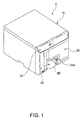
- the CD publisher 1 (simply “publisher 1" below) has a basically box-shaped case 31 with doors 32 and 33. Terms like “front”, “left”, “right”, “top”, “bottom”, “above” and “below” as used in the following description refer to the posture of the case 31 as shown in Fig. 1 with the doors 32 and 33 disposed at the front of the case 31.
- the doors 32 and 33 can open and close to the right and left, respectively.
- An operating panel 34 having indicators and operating buttons, for example, is disposed above the doors 32 and 33.
- a rectangular media exit 31 a is disposed below the door 32 and has a long side extending horizontally. The media exit 31a opens to the outside to allow processed media to be removed.
- a blank-media stacker 11 and a processed-media stacker 12 are disposed coaxially one above the other inside the case 31 on the right side thereof as seen from the front.
- the blank-media stacker 11 stores blank discs 2A that have not yet passed through a data writing process and a label printing process.
- the processed-media stacker 12 stores processed discs 2B that have undergone a data writing process and a label printing process, but the processed-media stacker 12 can also be used to store blank discs 2A as will be explained in more detail later. Note that the blank discs 2A and the processed discs 2B will be commonly referred to as discs 2
- the blank-media stacker 11 has a slide tray 41 that can be pulled out horizontally to the front, and a pair of left and right curved side walls 42 and 43 disposed vertically on top of the slide tray 41, thus rendering a stacker that receives discs 2 through its top opening and holds the discs 2 stacked coaxially.
- the task of storing or replenishing blank discs 2A in the blank-media stacker 11 can be done easily by opening the door 32 and pulling the slide tray 41 with the side walls 42 and 43 mounted thereon out to the front. This pulling-out makes the top opening of the blank-media stacker 11 accessible outside of the case 31.
- the processed-media stacker 12 below the blank-media stacker 11 is identically constructed, and has a slide tray 44 that can be pulled out horizontally to the front, and a pair of left and right curved side walls 45 and 46 disposed vertically on top of the slide tray 44, thus rendering a stacker that receives discs 2 through its top opening and holds the discs 2 stacked coaxially.
- the processed-media stacker 12 can be pulled out to the front to become easily accessible by pulling out the slide tray 44.
- the blank-media stacker 11 and the processed-media stacker 12 can each hold a plurality of discs 2 (50 discs each in this embodiment of the invention).
- a general purpose stacker 13 is disposed behind and to the left of the blank-media stacker 11 and the processed-media stacker 12.
- the general purpose stacker 13 can be used to store media that is rejected because the data writing process failed, or to store processed discs 2B.
- a discharge media stacker 14 that is used for discharging the processed discs 2B to the outside is located in front of the general purpose stacker 13.
- These stackers 13 and 14 have a common base 47 and side walls 48, 49, and 50 rising vertically from the base 47.
- the general purpose stacker 13 behind the discharge media stacker 14 comprises a storage space defined between the curved inner circumferential surface 48a of the rear side wall 48, and the curved inner circumferential surfaces 49a and 50a on the back side of the left and right side walls 49 and 50.
- the storage space stores the discs 2 stacked coaxially the discs being received through the top opening rendered by these side walls.
- the discharge media stacker 14 comprises a storage space defined between the curved inner circumferential surfaces 49b and 50b on the front side of the left and right side walls 49 and 50, and storing the discs 2 stacked coaxially the discs being received through the top opening rendered by these side walls.
- the general purpose stacker 13 can hold a plurality of discs 2, and the discharge media stacker 14 can also hold a plurality of discs 2.
- the number of discs 2 that can be stored in the general purpose stacker 13 is 30, and the number of discs 2 that can be stored in the discharge media stacker is 20.
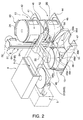
- a media transportation mechanism 6 is disposed behind the blank-media stacker 11 and the processed-media stacker 12.
- the media transportation mechanism 6 includes a chassis 51 that is attached vertically to the case 31, a vertical guide shaft 54 that rises vertically between top and bottom horizontal support plates 52 and 53 of the chassis 51, and a transportation arm 55 that is attached to this vertical guide shaft 54.
- the transportation arm 55 can travel up and down on the vertical guide shaft 54, and can pivot to the right and to the left around the vertical guide shaft 54.
- a media drive 4 and a label printer 5 are located behind the media transportation mechanism 6, one upon the other, i.e., the media drive 4 is disposed above the label printer 5.
- the media tray 71 of the media drive 4 is shown in a retracted position 71 B inside the media drive 4, and the printer tray 81 of the label printer 5 is shown in a rear position.
- the label printer 5 is an inkjet printer that uses ink cartridges (not shown in the figure) of one or more colors as the ink supply source, and the ink cartridges are installed in a cartridge housing (not shown in the figure).
- the stackers 11 to 13 are located on the path of travel of the transportation arm 55.
- a gap enabling this transportation arm 55 to ascend and descend is formed between the left and the right side walls 42 and 43 of the blank-media stacker 11 and between the left and the right side walls 45 and 46 of the processed-media stacker 12, respectively.
- Another gap is formed vertically between the bottom of the blank-media stacker 11 and the top of the processed-media stacker 12 so that the transportation arm 55 can pivot horizontally to a position directly above each of the media stackers.
- the transportation arm 55 can therefore be positioned at a location at a specified height inside each of the media stackers 11 and 12.
- the transportation arm 55 can also be positioned at a specified height inside the general purpose stacker 13 by pivoting and moving the transportation arm 55 to directly above the general purpose stacker 13, and then moving the transportation arm 55 vertically from this position to the specified height.
- the position directly above the general purpose stacker 13 is the front position of the printer tray 81, which is a media transfer position, and the position directly above this front position of the printer tray 81 is the media transfer position of the media tray 71. These media transfer positions are therefore also on the path of travel of the transportation arm 55.
- the discharge media stacker 14 is located in front of and beside the general purpose stacker 13, and is outside the pivot path of the transportation arm 55. That is, the discharge media stacker 14 is in a position outside of the path of travel of the transportation arm 55. How the processed discs 2B are stored in the discharge media stacker 14 in this embodiment of the invention is described below.
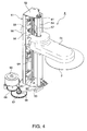
- FIG. 4 is a perspective view showing a specific example of the arrangement of the media transportation mechanism.
- the media transportation mechanism 6 has a chassis 51 that is attached perpendicularly to the case 31.
- the vertical guide shaft 54 is attached between the top and bottom horizontal support plates 52 and 53 of the chassis 51, and the transportation arm 55 is supported so that it can travel up and down and pivot on the vertical guide shaft 54.
- the elevator mechanism of the transportation arm 55 has an elevator motor 56. Torque from the elevator motor 56 is transferred to a drive pulley 61 through an intervening speed reducing gear train including a pinion 57 that is attached to the output shaft of the motor, a compound transfer gear 58, and a transfer gear 59.
- the drive pulley 61 is supported freely rotatably on a horizontal rotary shaft (not shown in the figure) near the top end of the chassis 51.
- a driven pulley 63 is supported freely rotatably on another horizontal rotary shaft (not shown in the figure) near the bottom end of the chassis 51.
- a timing belt 64 is mounted on the drive pulley 61 and driven pulley 63.
- the rear end part of the transportation arm 55 is fixed to the timing belt 64 on either the left or right side.
- the pivoting mechanism of the transportation arm 55 has a pivot motor 65.
- a pinion (not shown in the figure) is mounted on the output shaft of the pivot motor 65. Rotation of the pinion is transferred to a fan-shaped final gear 69 through an intervening speed reducing gear train including two compound transfer gears 66 and 67.
- the final gear 69 can pivot to the right and to the left around the vertical guide shaft 54.
- the chassis 51 in which the components of the elevator mechanism for the transportation arm 55 are assembled is mounted on the final gear 69.
- Driving the pivot motor 65 causes the final gear 69 to pivot to the right and to the left, and therefore also causes the chassis 51 that is mounted on the final gear 69 to pivot to the right and to the left around the vertical guide shaft 54.
- the transportation arm 55 that is held by the elevator mechanism mounted on the chassis 51 also pivots to the right and to the left around the vertical guide shaft 54.
- the transportation arm 55 has, for example, three gripping claws in the center at its distal (free) end, and one of the claws can move radially.
- a disc 2 can be gripped by inserting the claws into the center hole of the disc and moving one claw relative to the others radially to the outside. By returning the one claw radially to the inside from this gripping position, a processed disc 2 can be released and dropped from the gripping claws.
- FIG. 5 is a table of the relation between the starting and destination points that are set for controlling movement of the transportation arm.
- the positions denoted [1] to [6] indicate the positions of the distal end of the transportation arm 55 in FIG. 3 and correspond to the positions [1] to [6] in FIG. 5. More specifically, [1] is the home position (standby position) of the transportation arm 55, [2] is the position of the blank-media stacker 11, [3] is any position between the home position and the blank-media stacker 11, [4] is a midpoint or a point near to the midpoint of the vertical range of movement of the transportation arm 55, [5] is the position of the processed-media stacker 12, and [6] is any position between the midpoint and the processed-media stacker 12.
- Position [7] in FIG. 5 is any position between [1] and [4] in FIG. 3, or any position below [4]; position [8] in FIG. 5 is any position between [2] and [5] in FIG. 3, or any position below [5]. Position [9] in FIG. 5 is any position between [7] and [8].
- the transportation arm 55 normally moves along a preset path of travel.
- the path of travel (movement) is the path from any position [1] to [6] to any position [1], [2], [4], or [5]. More specifically, the path of travel is the path indicated by arrows A to J in FIG. 3, and position [9] is any position (including positions 7 and 8) that is not on this normal path of travel. More specifically, when the transportation arm 55 is at position [9], the transportation arm 55 may have unexpectedly stopped outside of the normal path of travel due, for example, to a problem that has occurred in the publisher 1.
- a respective arm detector is disposed at each of positions [1], [2], [4], and [5] so that the position of the transportation arm 55 can be detected. This embodiment of the invention calculates the distance to travel from the respective starting point [1], [2], [4], or [5] to the respective destination specified by a movement command, and moves the transportation arm 55 correspondingly.
- the transportation arm 55 When the transportation arm 55 is positioned at any of the positions [3], [6], [7], [8], and [9], the transportation arm 55 is first moved to one of the positions at which an arm detector is located (any of the positions [1], [2], [4], and [5]), the distance to travel is then calculated, and the arm is moved to the destination.
- the publisher 1 is connected to communicate with a host computer 100 and has a control unit 90 that controls driving the media transportation mechanism 6.
- the control unit 90 controls the movement of the transportation arm 55 according to a movement command received from the host computer 100.
- control unit 90 When the control unit 90 detects the transportation arm 55 by means of one of the detectors, the control unit 90 stores the detected position, that is, position [1], [2], [4], or [5], as the starting point. In this case, the control unit 90 functions as a position detection means and a memory means. The control unit 90 then calculates the distance of travel that the transportation arm 55 must move from this starting point to the destination specified by the movement command.
- control unit 90 moves the gripping claws disposed at the center of the distal end of the transportation arm 55 to grip a disc 2.
- control unit 90 lowers the transportation arm 55 at the destination and operates the gripping claws to release the disc 2.
- the transportation arm 55 is raised and stopped at the point where descent started.
- This embodiment of the invention moves the transportation arm 55 based on a movement command from the host computer 100, and then grips or releases the disc 2 at the destination based on a grip command or release command.
- Media transportation modes such as described below can therefore be set by combining plural movement commands and grip and release commands to grip and release a disc 2 by means of the gripping claws.
- the continuous processing mode is the processing mode for continuously producing a total 100 processed discs 2B.
- the processed discs 2B are stored in the general purpose stacker 13, the discharge media stacker 14, and the processed-media stacker 12 in the continuous processing mode. More specifically, the use of each stacker is not fixed but can be changed according to the operating mode.
- the transportation arm 55 can carry the discs 2 from any of the units including the media drive 4, the label printer 5, the blank-media stacker 11, and the processed-media stacker 12 to any of the units including the media drive 4, the label printer 5, the processed-media stacker 12, and the discharge media stacker 14.
- a plurality of media transportation routes can therefore be set, and the publisher 1 can be set to a variety of operating modes.
- step (1) in the normal processing mode is described next with reference to the flow chart in FIG. 6.
- step S11 When a command set including a first movement command that instructs the location of the blank-media stacker 11 as the destination, a grip command, a second movement command that instructs the location of the media drive 4 as the destination, and a release command is received (step S11 returns Yes), the distal end of the transportation arm 55 is first moved according to the first movement command to the position [2], i.e., the blank-media stacker 11 (step S12).
- step S12 The process of moving the transportation arm 55 in step S12 is described with reference to the flow chart in FIG. 7.
- step S21 When the control unit 90 receives a movement command (of the command set received in step S11 in FIG. 6) (step S21 returns Yes), the control unit 90 determines if the transportation arm 55 is located at position [1], [2], [4] or [5] (step S22). More specifically, the control unit 90 determines which of the positions [1], [2], [4] and [5], if any, is stored as the starting point of the transportation arm 55.
- step S22 If one of the positions [1], [2], [4] or [5] is stored as the starting point (step S22 returns Yes), the control unit 90 calculates the distance to travel from the stored starting point to the destination specified by the received movement command (step S23), and then moves the transportation arm 55 (step S24).
- the starting point of the transportation arm 55 is the home position [1] and the transportation arm 55 is moved according to the movement command that instructs the blank-media stacker 11 as the destination. If the movement is completed normally, the control unit 90 stores position [2], the blank-media stacker 11, as the next starting point.
- the path of travel in this case is represented by arrows A -> C in FIG. 3.
- the transportation arm is moved to position [1], the home position of the transportation arm 55.
- the path of travel in this case is represented by arrows H -> F -> J in FIG. 3.
- the transportation arm is moved to position [5], the location of the processed-media stacker 12.
- the path of travel in this case is represented by arrows I -> E -> G in FIG. 3.
- step S22 If in step S22 none of the positions [1], [2], [4] and [5] is stored as the starting point (step S22 returns No), whether the transportation arm 55 is moving is determined. If the transportation arm 55 is moving (step S25 returns Yes), the received movement command is not executed and the host computer 100 is informed that the transportation arm 55 is in motion (step S26). If movement of the transportation arm 55 has stopped, however, an error is returned to the host computer 100 (step S25 returns No, step S27).
- step S25 If the transportation arm 55 is not in motion in step S25 (step S25 returns No), the transportation arm 55 is outside the normal path of travel. The movement command is therefore not executed and an error is returned to the host computer 100 indicating that a destination that cannot be reached from the current location was specified (step S27).
- the motor could go out of step and stop unexpectedly while the transportation arm 55 is moving from position [1] to position [4] (the situation when the transportation arm 55 is at position [7] after the motor stops), or the motor could go out of step, for example, and stop unexpectedly while gripping or releasing a disc at position [2] or position [5] (the situation when the transportation arm 55 is at position [8] after the motor stops). If the transportation arm 55 thus stops abnormally, the movement command is not executed and an error report is returned to the host computer 100.
- the control unit 90 determines if the current position enables a normal control of the claw operation. Except for the case in which a disc 2 has already been gripped due to a command other than the grip command received in step S11, a condition in which a claw operation can be controlled normally is any condition in which the transportation arm 55 is positioned at a point where the disc 2 can be gripped.
- a condition in which the transportation arm 55 is positioned at a point where a disc 2 can be picked up is when the transportation arm 55 is positioned at one of the positions [1], [2], [4] and [5] where an arm detector is located. This is because the location of the transportation arm 55 is unknown if the transportation arm 55 is positioned at any position other than [1], [2], [4] or [5], and must therefore be moved to one of the positions at which an arm detector is located.
- step S13 If the control unit 90 determines that the transportation arm 55 is positioned where a disc 2 can be gripped (step S13 returns Yes), because position [2] at the blank-media stacker 11 is stored as the starting point, the claws are inserted into the center hole of the blank disc 2A and one claw is moved relative to the others radially to the outside to pick one blank disc 2A from the blank-media stacker 11 (step S14).
- step S13 determines that a disc 2 has already been gripped, or that the transportation arm 55 is positioned at a point where a disc 2 cannot be gripped, a gripping process abort report is returned to the host computer 100 without gripping a blank disc 2A.
- step S14 With a blank disc 2A gripped in step S14, the transportation arm 55 is moved to the home position at position [1] based on the movement command setting the position of the media drive 4 as the destination (step S15).
- the process of moving the transportation arm 55 in this case is the same as that described in step S12 with reference to the flow chart in FIG. 7. If moving the transportation arm 55 ends normally, the control unit 90 stores position [1] as the starting point.
- control unit 90 again determines if the current position enables driving and controlling the claws normally.
- step S16 the condition in which driving the claws can be controlled normally is when a disc 2 has already been gripped and the transportation arm 55 is positioned at a point where the gripped disc 2 can be released.
- step S16 If the control unit 90 determines that the transportation arm 55 is positioned at a point where the disc 2 can be released (step S16 returns Yes) because a disc 2 has been gripped and position [1], the home position, is stored as the starting point, the one claw is moved radially to the inside to release the blank disc 2A onto the media tray 71 of the media drive 4 (step S17).
- step S18 if is determined in step S16 that a disc 2 has not been gripped or the transportation arm 55 is positioned at a point where the blank disc 2A cannot be released, a releasing process abort error is reported to the host computer 100 without releasing the disc (step S18).
- step S13 when a blank disc 2A has been gripped, the gripped blank disc 2A may be dropped. Furthermore, if the claws are driven to release the disc in step S16 when a blank disc 2A has not been gripped, the operation is simply wasted.
- step S13 when the transportation arm 55 is positioned at a point where a disc cannot be gripped, there could be a safety-related problem with the media processing device and damage could result.
- This embodiment of the invention therefore does not execute the gripping and releasing operations in cases such as described above, and executes the grip command and the release command only when it is determined that driving the claws can be controlled normally. Operating errors can therefore be prevented.
- the host computer 100 is informed when the grip command or the release command is not executed, the user is alerted that the grip command or release command was not executed correctly.
- the control unit 90 in this embodiment of the invention does not execute the received movement command and returns an error report to the host computer 100.
- the host computer 100 thus knows that a problem with the publisher 1 has occurred. Issuing subsequent commands can therefore be blocked, the publisher 1 can be used safely, and the danger of damage occurring can be reduced.
- this embodiment of the invention reports to the host computer 100 that the movement command could not be executed.
- the danger of damage to the publisher 1 can therefore be reduced because issuing subsequent commands can be blocked and operating errors will not occur.
- FIG. 8 is a perspective view showing the appearance of a publisher according to this embodiment of the invention when the front doors are open
- FIG. 9 is a perspective view of the major internal parts of the publisher
- FIG. 10 is a schematic block diagram showing the mechanical arrangement of the publisher.
- this publisher 200 is a media processing device for writing data to disc-shaped media such as CD and DVD media (referred to as simply “discs” below) and for printing on the label side of the discs, and has a basically box-shaped case 102.
- a right door and a left door 103 and 104 that can open and close are disposed at the front of the case 102.
- Terms like "front”, “left”, “right”, “top”, “bottom”, “above” and “below” as used in the following description refer to the posture of the case 102 as shown in Fig. 8 with the doors 103 and 104 disposed at the front of the case 102.
- a drawer mechanism 107 is disposed between the left and right support legs 106.
- the door 103 on the right side as seen from the front opens and closes an opening 108 at the front of the publisher 200 as shown in FIG. 8, and is used for opening and closing the opening 108 in order to load unused (blank) discs M through the opening 108 or to remove finished discs M through the opening 108.
- the other door 104 on the left side as seen from the front is opened and closed to replace the ink cartridges 112 of the label printer 111 shown in FIG. 9. Opening the door 104 exposes a cartridge carrier 114, which has a plurality of cartridge holders 113 arranged vertically.
- a first media stacker 121 and a second media stacker 122 are disposed, one above the other, inside the case 102 of the publisher 200 so that the centers of discs M accommodated in these stackers are coaxially aligned.
- the first media stacker 121 stores a plurality (such as 50) of blank discs M that have not yet passed through the data writing process.
- the second media stacker 122 stores a plurality (such as 50) of blank discs M or processed discs M. Both the first media stacker 121 and the second media stacker 122 can be freely installed at and removed from a respectively prescribed position.
- the first media stacker 121 that is provided on top of the second media stacker 122 has a pair of right and left curved side walls 124 and 125 disposed so that the discs M can be received through a top opening and stored in a coaxial stack. Storing or replenishing discs M in the first media stacker 121 can be done easily by opening the door 103 and pulling the first media stacker 121 out.
- the second media stacker 122 is constructed in the same way as the first one and has a pair of right and left curved side walls 127 and 128, rendering a stacker that can receive the discs M through a top opening and store the discs M in a coaxial stack. Storing or replenishing discs M in the second media stacker 122 can be done easily by opening the door 103 and pulling the second media stacker 122 out.
- a transportation mechanism 131 for the discs is disposed behind the first media stacker 121 and the second media stacker 122.
- the transportation mechanism 131 has a vertical guide shaft 135 that rises vertically between a main frame 130 and a top plate 133 of a chassis 132.
- a transportation arm 136 is supported so that it can move vertically and pivot on this vertical guide shaft 135.
- a drive motor 137 enables the transportation arm 136 to move vertically along the vertical guide shaft 135 and to pivot to the right and to the left around the vertical guide shaft 135.
- Two media drives 141 are stacked vertically upon each other at the side of and behind the first and the second media stackers 121 and 122 and the transportation mechanism 131, and a carriage (not shown in the figure) of the label printer 111 is disposed movably below these media drives 141.
- Each of the media drives 141 has a media tray 141 a that can move between a position for writing data to the discs M and a transfer position for loading and unloading the discs M.
- the label printer 111 has a media tray 145 that can move between a printing position for printing a label on the label side of the discs M, and a transfer position for loading and unloading the discs M.
- FIG. 9 shows the media trays 141 a of the top and bottom media drives 141 pulled out to the transfer position, and the media tray 145 of the label printer 111 below the media drives 141 moved forward to the transfer position.
- the label printer 111 is an inkjet printer that uses ink cartridges 112 as the ink supply mechanism 160.
- This embodiment of the invention uses ink cartridges 112 in six different colors (black, cyan, magenta, yellow, light cyan, and light magenta).
- the ink cartridges 112 are loaded from the front into the cartridge holders 113 of the cartridge carrier 114.
- a gap enabling the transportation arm 136 of the transportation mechanism 131 to ascend and descend is formed between the left and right side walls 124 and 125 of the first media stacker 121, and between the left and right side walls 127 and 128 of the second media stacker 122.
- a gap is also formed between the first media stacker 121 and the second media stacker 122 so that the transportation arm 136 of the transportation mechanism 131 can pivot horizontally for positioning directly above the second media stacker 122.
- both media trays 141 a are positioned at the data writing position and the media tray 145 is moved to the inside to be positioned at the printing position, the transportation arm 136 of the transportation mechanism 131 can descend below the height of the media tray 145.
- a guide hole 165 is formed below the transfer position of the media tray 145 so that discs M released when the transportation arm 136 descends to this position pass through the guide hole 165.
- Another media stacker (a separate stacker) described below is disposed in this guide hole 165.
- the drawer mechanism 107 has a sliding tray 170 that can be pulled out from the main frame 130 to an open position, loaded, and then closed again by pushing it below the main frame 130.
- a stacker unit 171 rendered as an open recess is disposed in the sliding tray 170.
- the stacker unit 171 When the sliding tray 170 is in the storage position (closed position), the stacker unit 171 is positioned below the guide hole 165, and the center of the stacker unit 171 is positioned coaxially to the media trays 141 a and the media tray 145 in the transfer position.
- the stacker unit 171 receives discs M deposited through the guide hole 165, and stores only a relatively small number (such as 5 to 10) of discs M.
- the stacker unit 171 receives the discs M from the top and stores the discs M stacked coaxially.
- a third media stacker 172 (a separate stacker) with a larger disc storage capacity than the stacker unit 171 can be installed in and removed from the guide hole 165 and the stacker unit 171 of the sliding tray 170 in the storage position.
- This third media stacker 172 also has a pair of curved side walls 173 and 174, receives discs M through a top opening between the walls, and can store a plurality of (such as 50) discs M stacked coaxially.
- a gap enabling the transportation arm 136 of the transportation mechanism 131 to ascend and descend is formed between the left and right side walls 173 and 174.
- a handle 175 that is held by the user during installation and removal is disposed at a top part of one side wall 174.
- discs M can be stored in the third media stacker 172 after the discs have been removed as blank discs M from the lower second media stacker 122, recorded by one of the media drives 141 and printed the label printer 111.
- first media stacker 121 and the second media stacker 122 can both be loaded with discs M (blank media) to the maximum storage capacity (50 discs each), all discs M (50 discs) in the second media stacker 122 can be sequentially processed and subsequently stored in the third media stacker 172, and then all discs M (50 discs) in the first media stacker 121 can be sequentially processed and then stored in the emptied second media stacker 122 in a manner like that explained for the first embodiment.
- a number of discs M equal to the maximum storage capacity of the first media stacker 121 plus that of the second media stacker 122 (50 discs + 50 discs) can therefore be processed in one operation (batch processing mode).
- blank discs M can be taken from the first media stacker 121 or the second media stacker 122, data can be recorded by the media drives 141 and a label can be printed by the label printer 111, and the processed discs M can then be stored in the stacker unit 171 of the sliding tray 170 in the storage position.
- Discs M for which processing has been completed can thus be removed from the stacker unit 171 by pulling the sliding tray 170 out. More specifically, completed discs M can be removed one or multiple discs at a time while the discs M are processed and the door 103 remains closed (external discharge mode).
- the discs M can be desirably transported to the first media stacker 121, the second media stacker 122, the stacker unit 171 of the sliding tray 170 (or the third media stacker 172), the media tray 141a of each of the media drives 141, and the media tray 145 of the label printer 111.
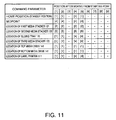
- FIG. 11 is a table of the relation between the starting and destination points that are set for controlling movement of the transportation arm.
- the positions denoted [1] to [6] indicate the positions of the distal (free) end of the transportation arm 136 in FIG. 10 and correspond to positions [1] to [6] in FIG. 11. More specifically, [1] is the home position (standby position) of the transportation arm 136, [2] is the position of the first media stacker 121, [3] is any position between the home position and the first media stacker 121, [4] is a midpoint or a point near to the midpoint of the vertical range of movement of the transportation arm 136, [5] is the position of the second media stacker 122, and [6] is any position between the midpoint and the second media stacker 122.
- Position [7] in FIG. 11 is any position between [1] and [4] in FIG. 10, or any position below [4]; position [8] in FIG. 11 is any position between [2] and [5] in FIG. 10, or any position below [5]. Position [9] in FIG. 11 is any position between [7] and [8].
- the transportation arm 136 normally moves along a preset path of travel.
- the path of travel (movement) is the path from any of the positions [1], [2], [4] and [5] to any of the positions [1], [2], [4], and [5]. More specifically, the path of travel is the path indicated by arrows A to J in FIG. 10, and position [9] is a position outside of this path of travel. More specifically, when the transportation arm 136 is at position [9], the transportation arm 136 may have unexpectedly stopped outside of the normal path of travel due, for example, to a problem that has occurred in the publisher 200.
- a respective arm detector is disposed at each of the positions [1], [2], [4], and [5] so that the position of the transportation arm 136 can be detected.
- This embodiment of the invention calculates the distance to travel from the starting point [1], [2], [4], or [5] to the destination specified by the movement command, and moves the transportation arm 136.
- the transportation arm 136 When the transportation arm 136 is positioned at position [3], [6], [7], [8], or [9], the transportation arm 136 first moves to one of the positions where an arm detector is located (any of positions [1], [2], [4], and [5]), the distance to travel is then calculated, and the arm is moved to the destination.
- the publisher 200 is connected to communicate with a host computer 100, and the publisher 200 has a control unit 190 that controls driving the transportation mechanism 131.
- the control unit 190 controls moving the transportation arm 136 according to a movement command received from the host computer 100.
- control unit 190 When the control unit 190 detects the transportation arm 136 by means of one of the arm detectors, the control unit 190 stores the detected position, that is, position [1], [2], [4], or [5], as the starting point. In this case the control unit 190 functions as a position detection means and a memory means. The control unit 190 then calculates the distance of travel that the transportation arm 136 must move from this starting point to the destination specified by the movement command from the host computer 100.
- control unit 190 moves gripping claws disposed at the center of the distal end of the transportation arm 136 to grip discs M.
- control unit 190 also lowers the transportation arm 136 at the destination, and operates the gripping claws to release the discs M.
- the transportation arm 136 is raised and stopped at the point where descent started.
- This embodiment of the invention moves the transportation arm 136 based on a movement command from the host computer 100, and then grips or releases a disc M at the destination based on a grip command or release command.
- the media transportation modes (operating modes) described above can therefore be set by combining plural movement commands for the transportation arm 136 and grip and release commands for gripping and releasing a disc M by means of the gripping claws. Some media transportation modes are described below.
- the external discharge mode is used when the third media stacker 172 is removed.
- the batch processing mode is used when the third media stacker 172 is installed.
- the first media stacker 121 and the second media stacker 122 are loaded with blank discs M to the maximum storage capacity. This is a processing mode for continuously producing 100 discs M if 50 discs are loaded into each of the first and second stackers.
- the processed discs M are stored in the third media stacker 172 and the second media stacker 122. More specifically, the use of each stacker is not fixed, but can be changed according to the operating mode.
- the transportation arm 136 can carry discs M from any of the units including the media drives 141, the label printer 111, the first media stacker 121, and the second media stacker 122 to any of the units including the media drives 141, the label printer 111, the sliding tray 170, the second media stacker 122, and the third media stacker 172.
- a plurality of media transportation routes can therefore be set, and the publisher 200 can be set to a variety of operating modes.
- step (1) in the external discharge mode The disc gripping or releasing process executed in step (1) in the external discharge mode is described next with reference to the flow chart in FIG. 6.
- step S11 When a command set including a movement command setting the location of the first media stacker 121 as the destination, a grip command, a movement command setting the location of a media drive 141 as the destination, and a release command is received (step S11 returns Yes), the distal end of the transportation arm 136 is moved according to the movement command to the position [2] of the first media stacker 121 (step S12).
- step S12 The process of moving the transportation arm 136 in step S12 is described with reference to the flow chart in FIG. 7.
- step S21 When the control unit 190 receives a movement command (of the command set received in step S11 in FIG. 6) (step S21 returns Yes), the control unit 190 determines if the transportation arm 136 is located at position [1], [2], [4] or [5] (step S22). More specifically, the control unit 190 determines which of the positions [1], [2], [4] and [5], if any, is stored as the starting point of the transportation arm 136.
- step S22 If one of the positions [1], [2], [4] or [5] is stored as the starting point (step S22 returns Yes), the control unit 190 calculates the distance to travel from the stored starting point to the destination specified by the received movement command (step S23), and then moves the transportation arm 136 (step S24).
- the starting point of the transportation arm 136 is the home position [1] and the transportation arm 136 is moved according to the movement command that instructs the first media stacker 121 as the destination. If the movement is completed normally, the control unit 190 stores position [2], the first media stacker 121, as the next starting point.
- the path of travel in this case is represented by arrows A -> C in FIG. 10.
- the transportation arm is moved to position [1], the home position of the transportation arm 136.
- the path of travel in this case is represented by arrows H -> F -> J in FIG. 10.
- the transportation arm is also moved to position [1], the home position of the transportation arm 136.
- the path of travel in this case is represented by arrows D -> B in FIG. 10.
- the transportation arm 136 If the starting point stored by the control unit 190 is position [1], the home position of the transportation arm 136, and the received movement command specifies the position of the second media stacker 122 as the destination, the transportation arm is moved to position [5], the location of the second media stacker 122.
- the path of travel in this case is represented by arrows I -> E -> G in FIG. 10.
- step S22 If in step S22 none of the positions [1], [2], [4] and [5] is stored as the starting point (step S22 returns No), whether the transportation arm 136 is moving is determined. If the transportation arm 136 is moving (step S25 returns Yes), the received movement command is not executed and the host computer 100 is informed that the transportation arm 136 is in motion (step S26). If movement of the transportation arm 136 has stopped, however, an error is returned to the host computer 100 (step S25 returns No, step S27).
- step S25 If the transportation arm 136 is not in motion in step S25 (step S25 returns No), the transportation arm 136 is outside the normal path of travel. The movement command is therefore not executed and an error is returned to the host computer 100 indicating that a destination that cannot be reached from the current location was specified (step S27).
- the motor could go out of step and stop unexpectedly while the transportation arm 136 is moving from position [1] to position [4] (the situation when the transportation arm 136 is at position [7] after the motor stops), or the motor could go out of step, for example, and stop unexpectedly while gripping or releasing a disc M at position [2] or position [5] (the situation when the transportation arm 136 is at position [8] after the motor stops). If the transportation arm 136 thus stops abnormally, the movement command is not executed and an error report is returned to the host computer 100.
- the control unit 190 determines if the current position enables a normal control of the claw operation. Except for the case in which a disc M has already been gripped due to a command other than the grip command received in step S11, a condition in which a claw operation can be controlled normally is any condition in which the transportation arm 136 is positioned at a point where a disc M can be gripped.
- a condition in which the transportation arm 136 is positioned at a point where a disc M can be gripped is when the transportation arm 136 is positioned at one of the positions [1], [2], [4] and [5] where an arm detector is located. This is because the location of the transportation arm 136 is unknown if the transportation arm 136 is positioned at any position other than [1], [2], [4] or [5], and must therefore be moved to one of the positions at which an arm detector is located.
- step S13 If the control unit 190 determines that the transportation arm 136 is positioned where a disc M can be gripped (step S13 returns Yes), because position [2] at the first media stacker 121 is stored as the starting point, the claws are inserted to the center hole of the discs M and one claw is moved relative to the others radially to the outside to grip one disc M from the first media stacker 121 (step S14).
- step S13 determines that a disc M has already been gripped, or that the transportation arm 136 is positioned at a point where a disc M cannot be gripped, a gripping process abort report is returned to the host computer 100 without gripping the discs M.
- step S14 With a disc M gripped in step S14, the transportation arm 136 is moved to the home position at position [1] based on the movement command setting the position of the media drive 141 as the destination (step S15).
- the process of moving the transportation arm 136 in this case is the same as that described in step S12 with reference to the flow chart in FIG. 7. If moving the transportation arm 136 ends normally, the control unit 190 stores the position [1] as the starting point.
- control unit 90 again determines if the current position enables driving and controlling the claws normally.
- step S16 the condition in which driving the claws can be controlled normally is when a disc M has already been gripped and the transportation arm 136 is positioned at a point where the gripped disc M can be released.
- step S16 If the control unit 190 determines that the transportation arm 136 is positioned at a point where the disc M can be released (step S16 returns Yes) because a disc M has been gripped and position [1], the home position, is stored as the starting point, the one claw is moved radially to the inside to release the disc M onto the media tray 141a of the media drive 141 (step S17).
- step S16 if is determined in step S16 that a disc M has not been gripped or the transportation arm 136 is positioned at a point where the disc M cannot be released, a releasing process abort error is reported to the host computer 100 without releasing the disc (step S18).
- step S13 when a disc M has been gripped, the gripped disc M may be dropped. Furthermore, if the claws are driven to release the disc in step S16 when a disc M has not been gripped, the operation is simply wasted.
- step S13 when the transportation arm 136 is positioned at a point where a disc cannot be gripped, there could be a safety-related problem with the media processing device and damage could result.
- This embodiment of the invention therefore does not execute the gripping and releasing operations in cases such as described above, and executes the grip command and release command only when it is determined that driving the claws can be controlled normally. Operating errors can therefore be prevented.
- the host computer 100 is informed when the grip command or release command is not executed, the user is alerted that the grip command or release command was not executed correctly.
- the control unit 190 in this embodiment of the invention does not execute the received movement command and returns an error report to the host computer 100.
- the host computer 100 can thus know that a problem with the publisher 200 has occurred. Issuing subsequent commands can therefore be blocked, the publisher 200 can be used safely, and the danger of damage occurring can be reduced.
- this embodiment of the invention reports to the host computer 100 that the movement command could not be executed.
- the danger of damage to the publisher 200 can therefore be reduced because issuing subsequent commands can be blocked and operating errors will not occur.
Abstract
Description
- The present invention relates to a media processing device that writes data to data carrier media such as CD and DVD discs, and prints on a label side of the media.
- Media processing devices that write data to data carrier media (simply referred to a "media" hereinafter) such as CD and DVD discs and print on the label side of the media are known. These media processing devices have a transportation mechanism for carrying media to the different processing stations inside the system. The transportation mechanism carries a blank medium stored in a blank-media stacker to the an internal media drive, and after writing data to the blank medium carries the processed medium to a processed-media stacker. After writing data to a medium, the medium is carried to an internal label printer, and after label printing the processed medium is transported to the processed-media stacker or a media exit. See, for example,
JP-A-2000-260172 JP-A-2002-056584 -
JP-A-2002-334552 -
JP-A-2004-273048 - A media processing device according to the pre-characterizing portion of
claim 1 is disclosed inUS 6,400,659 B1 . - A problem with the media processing devices described above is that if a problem occurs during a media transportation operation and the transportation process is not completed normally, the media processing device will execute the next process as commanded because there is no means for recognizing that such a problem has occurred. This can result in unexpected problems such as media not being stored in the intended stacker and being dropped outside the stacker. If left uncorrected, this can result in damage to the media processing device.
- An object of the present invention is provide a media processing device and a method of controlling it that allow preventing events that may lead to damage to the media processing device if a medium being processed cannot be conveyed to any one of the data writing means, the printing means, and the media storage means in response to a command from the host computer.
- This object is achieved by a media processing device as claimed in
claim 1 and a method as claimed inclaim 7. Preferred embodiments of the invention are defined in the dependent claims. - When a medium cannot be transported as instructed by the host computer, the media processing device according to the invention reports an error to the host computer and the host computer can therefore know that there is a problem with the media processing device. Issuing a next command can therefore be prevented. The media processing device can therefore be used safely, and the danger of causing damage can be reduced.
- Other objects and attainments together with a fuller understanding of the invention will become apparent and appreciated by referring to the following description of preferred embodiments taken in conjunction with the accompanying drawings, in which:
- FIG. 1
- is a schematic view of a publisher as a first embodiment according to the present invention;
- FIG. 2
- is a perspective view showing the main internal parts of the first embodiment;
- FIG. 3
- is a schematic view showing the mechanical arrangement of the publisher of the first embodiment;
- FIG.4
- is a perspective view showing a specific example of the arrangement of the media transportation mechanism of the first embodiment;
- FIG. 5
- is a table of the relation between the starting and destination points that are set for controlling movement of the transportation arm;
- FIG. 6
- is a flow chart describing the gripping or releasing operations;
- FIG. 7
- is a flow chart describing the process for moving the transportation arm;
- FIG. 8
- is a perspective view showing the main internal parts of a publisher according to a second embodiment of the invention;
- FIG. 9
- is a perspective view of showing the major internal parts of the second embodiment;
- FIG. 10
- is a schematic block diagram showing the mechanical arrangement of the second embodiment; and
- FIG. 11
- is a table of the relation between the starting and destination points that are set for controlling movement of the transportation arm according to the second embodiment.
- A CD publisher is described below as a first embodiment of a media processing device according to the present invention in which CDs (referred to as discs below) are the data carrier media to be processed.
- The CD publisher 1 (simply "
publisher 1" below) has a basically box-shaped case 31 withdoors case 31 as shown in Fig. 1 with thedoors case 31. Thedoors operating panel 34 having indicators and operating buttons, for example, is disposed above thedoors rectangular media exit 31 a is disposed below thedoor 32 and has a long side extending horizontally. Themedia exit 31a opens to the outside to allow processed media to be removed. - A blank-
media stacker 11 and a processed-media stacker 12 are disposed coaxially one above the other inside thecase 31 on the right side thereof as seen from the front. The blank-media stacker 11 storesblank discs 2A that have not yet passed through a data writing process and a label printing process. The processed-media stacker 12 stores processeddiscs 2B that have undergone a data writing process and a label printing process, but the processed-media stacker 12 can also be used to storeblank discs 2A as will be explained in more detail later. Note that theblank discs 2A and the processeddiscs 2B will be commonly referred to asdiscs 2 - The blank-
media stacker 11 has aslide tray 41 that can be pulled out horizontally to the front, and a pair of left and rightcurved side walls slide tray 41, thus rendering a stacker that receivesdiscs 2 through its top opening and holds thediscs 2 stacked coaxially. The task of storing or replenishingblank discs 2A in the blank-media stacker 11 can be done easily by opening thedoor 32 and pulling theslide tray 41 with theside walls media stacker 11 accessible outside of thecase 31. - The processed-
media stacker 12 below the blank-media stacker 11 is identically constructed, and has aslide tray 44 that can be pulled out horizontally to the front, and a pair of left and rightcurved side walls slide tray 44, thus rendering a stacker that receivesdiscs 2 through its top opening and holds thediscs 2 stacked coaxially. Like the blank-media stacker 11, the processed-media stacker 12 can be pulled out to the front to become easily accessible by pulling out theslide tray 44. - The blank-
media stacker 11 and the processed-media stacker 12 can each hold a plurality of discs 2 (50 discs each in this embodiment of the invention). - A
general purpose stacker 13 is disposed behind and to the left of the blank-media stacker 11 and the processed-media stacker 12. Thegeneral purpose stacker 13 can be used to store media that is rejected because the data writing process failed, or to store processeddiscs 2B. Adischarge media stacker 14 that is used for discharging the processeddiscs 2B to the outside is located in front of thegeneral purpose stacker 13. Thesestackers common base 47 andside walls base 47. - The
general purpose stacker 13 behind thedischarge media stacker 14 comprises a storage space defined between the curved innercircumferential surface 48a of therear side wall 48, and the curved innercircumferential surfaces right side walls discs 2 stacked coaxially the discs being received through the top opening rendered by these side walls. - The
discharge media stacker 14 comprises a storage space defined between the curved innercircumferential surfaces right side walls discs 2 stacked coaxially the discs being received through the top opening rendered by these side walls. - The
general purpose stacker 13 can hold a plurality ofdiscs 2, and thedischarge media stacker 14 can also hold a plurality ofdiscs 2. As an example, the number ofdiscs 2 that can be stored in thegeneral purpose stacker 13 is 30, and the number ofdiscs 2 that can be stored in the discharge media stacker is 20. - As shown in FIG. 2 and FIG. 3, a
media transportation mechanism 6 is disposed behind the blank-media stacker 11 and the processed-media stacker 12. Themedia transportation mechanism 6 includes achassis 51 that is attached vertically to thecase 31, avertical guide shaft 54 that rises vertically between top and bottomhorizontal support plates chassis 51, and atransportation arm 55 that is attached to thisvertical guide shaft 54. Thetransportation arm 55 can travel up and down on thevertical guide shaft 54, and can pivot to the right and to the left around thevertical guide shaft 54. - A
media drive 4 and alabel printer 5 are located behind themedia transportation mechanism 6, one upon the other, i.e., the media drive 4 is disposed above thelabel printer 5. In FIG. 2 themedia tray 71 of the media drive 4 is shown in a retractedposition 71 B inside themedia drive 4, and theprinter tray 81 of thelabel printer 5 is shown in a rear position. Thelabel printer 5 is an inkjet printer that uses ink cartridges (not shown in the figure) of one or more colors as the ink supply source, and the ink cartridges are installed in a cartridge housing (not shown in the figure). - The
stackers 11 to 13 are located on the path of travel of thetransportation arm 55. A gap enabling thistransportation arm 55 to ascend and descend is formed between the left and theright side walls media stacker 11 and between the left and theright side walls media stacker 12, respectively. Another gap is formed vertically between the bottom of the blank-media stacker 11 and the top of the processed-media stacker 12 so that thetransportation arm 55 can pivot horizontally to a position directly above each of the media stackers. Thetransportation arm 55 can therefore be positioned at a location at a specified height inside each of themedia stackers - The
transportation arm 55 can also be positioned at a specified height inside thegeneral purpose stacker 13 by pivoting and moving thetransportation arm 55 to directly above thegeneral purpose stacker 13, and then moving thetransportation arm 55 vertically from this position to the specified height. - The position directly above the
general purpose stacker 13 is the front position of theprinter tray 81, which is a media transfer position, and the position directly above this front position of theprinter tray 81 is the media transfer position of themedia tray 71. These media transfer positions are therefore also on the path of travel of thetransportation arm 55. - The
discharge media stacker 14 is located in front of and beside thegeneral purpose stacker 13, and is outside the pivot path of thetransportation arm 55. That is, thedischarge media stacker 14 is in a position outside of the path of travel of thetransportation arm 55. How the processeddiscs 2B are stored in thedischarge media stacker 14 in this embodiment of the invention is described below. - The mechanical arrangement of the media transportation mechanism is described next with reference to FIG. 4. FIG. 4 is a perspective view showing a specific example of the arrangement of the media transportation mechanism.
- As described above the
media transportation mechanism 6 has achassis 51 that is attached perpendicularly to thecase 31. Thevertical guide shaft 54 is attached between the top and bottomhorizontal support plates chassis 51, and thetransportation arm 55 is supported so that it can travel up and down and pivot on thevertical guide shaft 54. - The elevator mechanism of the
transportation arm 55 has anelevator motor 56. Torque from theelevator motor 56 is transferred to a drivepulley 61 through an intervening speed reducing gear train including apinion 57 that is attached to the output shaft of the motor, acompound transfer gear 58, and atransfer gear 59. Thedrive pulley 61 is supported freely rotatably on a horizontal rotary shaft (not shown in the figure) near the top end of thechassis 51. - A driven
pulley 63 is supported freely rotatably on another horizontal rotary shaft (not shown in the figure) near the bottom end of thechassis 51. Atiming belt 64 is mounted on thedrive pulley 61 and drivenpulley 63. The rear end part of thetransportation arm 55 is fixed to thetiming belt 64 on either the left or right side. As a result, when theelevator motor 56 is driven, thetiming belt 64 travels vertically in a loop, and thetransportation arm 55 attached to thetiming belt 64 travels vertically on thevertical guide shaft 54. - The pivoting mechanism of the
transportation arm 55 has apivot motor 65. A pinion (not shown in the figure) is mounted on the output shaft of thepivot motor 65. Rotation of the pinion is transferred to a fan-shapedfinal gear 69 through an intervening speed reducing gear train including two compound transfer gears 66 and 67. Thefinal gear 69 can pivot to the right and to the left around thevertical guide shaft 54. Thechassis 51 in which the components of the elevator mechanism for thetransportation arm 55 are assembled is mounted on thefinal gear 69. Driving thepivot motor 65 causes thefinal gear 69 to pivot to the right and to the left, and therefore also causes thechassis 51 that is mounted on thefinal gear 69 to pivot to the right and to the left around thevertical guide shaft 54. As a result, thetransportation arm 55 that is held by the elevator mechanism mounted on thechassis 51 also pivots to the right and to the left around thevertical guide shaft 54. - The
transportation arm 55 has, for example, three gripping claws in the center at its distal (free) end, and one of the claws can move radially. Adisc 2 can be gripped by inserting the claws into the center hole of the disc and moving one claw relative to the others radially to the outside. By returning the one claw radially to the inside from this gripping position, a processeddisc 2 can be released and dropped from the gripping claws. - The operation of the
publisher 1 according to this embodiment of the invention is described next with reference to FIG. 3 and FIG. 5. FIG. 5 is a table of the relation between the starting and destination points that are set for controlling movement of the transportation arm. - The positions denoted [1] to [6] indicate the positions of the distal end of the
transportation arm 55 in FIG. 3 and correspond to the positions [1] to [6] in FIG. 5. More specifically, [1] is the home position (standby position) of thetransportation arm 55, [2] is the position of the blank-media stacker 11, [3] is any position between the home position and the blank-media stacker 11, [4] is a midpoint or a point near to the midpoint of the vertical range of movement of thetransportation arm 55, [5] is the position of the processed-media stacker 12, and [6] is any position between the midpoint and the processed-media stacker 12. - Position [7] in FIG. 5 is any position between [1] and [4] in FIG. 3, or any position below [4]; position [8] in FIG. 5 is any position between [2] and [5] in FIG. 3, or any position below [5]. Position [9] in FIG. 5 is any position between [7] and [8].
- The
transportation arm 55 normally moves along a preset path of travel. In this embodiment of the invention the path of travel (movement) is the path from any position [1] to [6] to any position [1], [2], [4], or [5]. More specifically, the path of travel is the path indicated by arrows A to J in FIG. 3, and position [9] is any position (includingpositions 7 and 8) that is not on this normal path of travel. More specifically, when thetransportation arm 55 is at position [9], thetransportation arm 55 may have unexpectedly stopped outside of the normal path of travel due, for example, to a problem that has occurred in thepublisher 1. A respective arm detector is disposed at each of positions [1], [2], [4], and [5] so that the position of thetransportation arm 55 can be detected. This embodiment of the invention calculates the distance to travel from the respective starting point [1], [2], [4], or [5] to the respective destination specified by a movement command, and moves thetransportation arm 55 correspondingly. - When the
transportation arm 55 is positioned at any of the positions [3], [6], [7], [8], and [9], thetransportation arm 55 is first moved to one of the positions at which an arm detector is located (any of the positions [1], [2], [4], and [5]), the distance to travel is then calculated, and the arm is moved to the destination. - As shown in FIG. 3, the
publisher 1 is connected to communicate with ahost computer 100 and has acontrol unit 90 that controls driving themedia transportation mechanism 6. Thecontrol unit 90 controls the movement of thetransportation arm 55 according to a movement command received from thehost computer 100. - When the
control unit 90 detects thetransportation arm 55 by means of one of the detectors, thecontrol unit 90 stores the detected position, that is, position [1], [2], [4], or [5], as the starting point. In this case, thecontrol unit 90 functions as a position detection means and a memory means. Thecontrol unit 90 then calculates the distance of travel that thetransportation arm 55 must move from this starting point to the destination specified by the movement command. - In response to a media grip command from the
host computer 100, thecontrol unit 90 moves the gripping claws disposed at the center of the distal end of thetransportation arm 55 to grip adisc 2. In response to a release command from thehost computer 100, thecontrol unit 90 lowers thetransportation arm 55 at the destination and operates the gripping claws to release thedisc 2. When thedisc 2 has been released, thetransportation arm 55 is raised and stopped at the point where descent started. - This embodiment of the invention moves the
transportation arm 55 based on a movement command from thehost computer 100, and then grips or releases thedisc 2 at the destination based on a grip command or release command. Media transportation modes (operating modes) such as described below can therefore be set by combining plural movement commands and grip and release commands to grip and release adisc 2 by means of the gripping claws. -
- (1) A
blank disc 2A is picked up from the blank-media stacker 11, carried to themedia drive 4, and released there. - (2) The media drive 4 writes data to the
blank disc 2A. - (3) The
disc 2 is picked up from themedia drive 4, carried to thelabel printer 5, and released there. - (4) The
label printer 5 prints a label on the label side of the disc. - (5) The processed
disc 2B is picked up from thelabel printer 5, carried to thedischarge media stacker 14, and released there. - In this mode,
blank discs 2A are stored in both the blank-media stacker 11 and the processed-media stacker 12 to the storage capacity of the stackers. If each stacker can hold 50 discs for a total storage capacity of 100 discs, the continuous processing mode is the processing mode for continuously producing a total 100 processeddiscs 2B. - (1) A
blank disc 2A is picked up from the processed-media stacker 12, carried to themedia drive 4, and released there. - (2) The media drive 4 writes data to the
blank disc 2A. - (3) The
disc 2 is picked up from themedia drive 4, carried to thelabel printer 5, and released there. - (4) The
label printer 5 prints a label on the label side of the disc. - (5) The
disc 2 is picked up from thelabel printer 5, carried to thegeneral purpose stacker 13, and released there. - (6) The sequence of steps (1) to (5) is repeated continuously for the next 29 discs.
- (7) A
blank disc 2A is picked up from the processed-media stacker 12 in which 20 discs remain, carried to themedia drive 4, and released there. - (8) After executing steps (2) and (4), the processed
disc 2B is picked up from thelabel printer 5, carried to thedischarge media stacker 14, and released there. - (9) The sequence of steps (7) and (8) is repeated continuously for the next 19 discs.
- (10) A
blank disc 2A is picked up from the blank-media stacker 11, carried to themedia drive 4, and released there. - (11) After executing steps (2) to (4), the processed
disc 2B is picked up from thelabel printer 5, carried to the processed-media stacker 12, and released there. - (12) The sequence of steps (10) and (11) is repeated continuously for the next 49 discs.
- The processed
discs 2B are stored in thegeneral purpose stacker 13, thedischarge media stacker 14, and the processed-media stacker 12 in the continuous processing mode. More specifically, the use of each stacker is not fixed but can be changed according to the operating mode. - The media transportation modes described above are examples only, and other modes are conceivable. In this embodiment of the invention the
transportation arm 55 can carry thediscs 2 from any of the units including themedia drive 4, thelabel printer 5, the blank-media stacker 11, and the processed-media stacker 12 to any of the units including themedia drive 4, thelabel printer 5, the processed-media stacker 12, and thedischarge media stacker 14. A plurality of media transportation routes can therefore be set, and thepublisher 1 can be set to a variety of operating modes. - The disc gripping or releasing process executed in step (1) in the normal processing mode is described next with reference to the flow chart in FIG. 6.
- When a command set including a first movement command that instructs the location of the blank-
media stacker 11 as the destination, a grip command, a second movement command that instructs the location of the media drive 4 as the destination, and a release command is received (step S11 returns Yes), the distal end of thetransportation arm 55 is first moved according to the first movement command to the position [2], i.e., the blank-media stacker 11 (step S12). - The process of moving the
transportation arm 55 in step S12 is described with reference to the flow chart in FIG. 7. - When the
control unit 90 receives a movement command (of the command set received in step S11 in FIG. 6) (step S21 returns Yes), thecontrol unit 90 determines if thetransportation arm 55 is located at position [1], [2], [4] or [5] (step S22). More specifically, thecontrol unit 90 determines which of the positions [1], [2], [4] and [5], if any, is stored as the starting point of thetransportation arm 55. - If one of the positions [1], [2], [4] or [5] is stored as the starting point (step S22 returns Yes), the
control unit 90 calculates the distance to travel from the stored starting point to the destination specified by the received movement command (step S23), and then moves the transportation arm 55 (step S24). - Let us assume, the starting point of the
transportation arm 55 is the home position [1] and thetransportation arm 55 is moved according to the movement command that instructs the blank-media stacker 11 as the destination. If the movement is completed normally, thecontrol unit 90 stores position [2], the blank-media stacker 11, as the next starting point. The path of travel in this case is represented by arrows A -> C in FIG. 3. - If the starting point stored by the
control unit 90 is position [5], i.e., the processed-media stacker 12, and the received movement command specifies the position of the media drive 4 as the destination, the transportation arm is moved to position [1], the home position of thetransportation arm 55. The path of travel in this case is represented by arrows H -> F -> J in FIG. 3. - When the starting point stored by the
control unit 90 is position [2], that is, the blank-media stacker 11, and the received movement command specifies the position of theprinter tray 81 as the destination, the transportation arm is also moved to position [1], the home position of thetransportation arm 55. The path of travel in this case is represented by arrows D -> B in FIG. 3. - If the starting point stored by the
control unit 90 is position [1], the home position of thetransportation arm 55, and the received movement command specifies the position of the processed-media stacker 12 as the destination, the transportation arm is moved to position [5], the location of the processed-media stacker 12. The path of travel in this case is represented by arrows I -> E -> G in FIG. 3. - If in step S22 none of the positions [1], [2], [4] and [5] is stored as the starting point (step S22 returns No), whether the
transportation arm 55 is moving is determined. If thetransportation arm 55 is moving (step S25 returns Yes), the received movement command is not executed and thehost computer 100 is informed that thetransportation arm 55 is in motion (step S26). If movement of thetransportation arm 55 has stopped, however, an error is returned to the host computer 100 (step S25 returns No, step S27). - If the
transportation arm 55 is not in motion in step S25 (step S25 returns No), thetransportation arm 55 is outside the normal path of travel. The movement command is therefore not executed and an error is returned to thehost computer 100 indicating that a destination that cannot be reached from the current location was specified (step S27). - For example, the motor could go out of step and stop unexpectedly while the
transportation arm 55 is moving from position [1] to position [4] (the situation when thetransportation arm 55 is at position [7] after the motor stops), or the motor could go out of step, for example, and stop unexpectedly while gripping or releasing a disc at position [2] or position [5] (the situation when thetransportation arm 55 is at position [8] after the motor stops). If thetransportation arm 55 thus stops abnormally, the movement command is not executed and an error report is returned to thehost computer 100. - Referring again to FIG. 6, the process of gripping or releasing a disc is described next.
- When the
transportation arm 55 moves to the blank-media stacker 11 (step S12), thecontrol unit 90 determines if the current position enables a normal control of the claw operation. Except for the case in which adisc 2 has already been gripped due to a command other than the grip command received in step S11, a condition in which a claw operation can be controlled normally is any condition in which thetransportation arm 55 is positioned at a point where thedisc 2 can be gripped. - A condition in which the
transportation arm 55 is positioned at a point where adisc 2 can be picked up is when thetransportation arm 55 is positioned at one of the positions [1], [2], [4] and [5] where an arm detector is located. This is because the location of thetransportation arm 55 is unknown if thetransportation arm 55 is positioned at any position other than [1], [2], [4] or [5], and must therefore be moved to one of the positions at which an arm detector is located. - If the
control unit 90 determines that thetransportation arm 55 is positioned where adisc 2 can be gripped (step S13 returns Yes), because position [2] at the blank-media stacker 11 is stored as the starting point, the claws are inserted into the center hole of theblank disc 2A and one claw is moved relative to the others radially to the outside to pick oneblank disc 2A from the blank-media stacker 11 (step S14). - If step S13 determines that a
disc 2 has already been gripped, or that thetransportation arm 55 is positioned at a point where adisc 2 cannot be gripped, a gripping process abort report is returned to thehost computer 100 without gripping ablank disc 2A. - With a
blank disc 2A gripped in step S14, thetransportation arm 55 is moved to the home position at position [1] based on the movement command setting the position of the media drive 4 as the destination (step S15). The process of moving thetransportation arm 55 in this case is the same as that described in step S12 with reference to the flow chart in FIG. 7. If moving thetransportation arm 55 ends normally, thecontrol unit 90 stores position [1] as the starting point. - Next, the
control unit 90 again determines if the current position enables driving and controlling the claws normally. - In step S16 the condition in which driving the claws can be controlled normally is when a
disc 2 has already been gripped and thetransportation arm 55 is positioned at a point where the grippeddisc 2 can be released. - If the
control unit 90 determines that thetransportation arm 55 is positioned at a point where thedisc 2 can be released (step S16 returns Yes) because adisc 2 has been gripped and position [1], the home position, is stored as the starting point, the one claw is moved radially to the inside to release theblank disc 2A onto themedia tray 71 of the media drive 4 (step S17). - However, if is determined in step S16 that a
disc 2 has not been gripped or thetransportation arm 55 is positioned at a point where theblank disc 2A cannot be released, a releasing process abort error is reported to thehost computer 100 without releasing the disc (step S18). - Note that if the claws are driven to be closed in step S13 when a
blank disc 2A has been gripped, the grippedblank disc 2A may be dropped. Furthermore, if the claws are driven to release the disc in step S16 when ablank disc 2A has not been gripped, the operation is simply wasted. - Furthermore, if the claws are driven in step S13 when the
transportation arm 55 is positioned at a point where a disc cannot be gripped, there could be a safety-related problem with the media processing device and damage could result. - In addition, if the claws are driven when the
transportation arm 55 is positioned at a point where a disc cannot be released, there could be a safety-related problem with the media processing device and damage could result. - This embodiment of the invention therefore does not execute the gripping and releasing operations in cases such as described above, and executes the grip command and the release command only when it is determined that driving the claws can be controlled normally. Operating errors can therefore be prevented.
- Furthermore, because the
host computer 100 is informed when the grip command or the release command is not executed, the user is alerted that the grip command or release command was not executed correctly. - As described above, if the starting point of the
transportation arm 55 when a movement command is received from thehost computer 100 is any point not corresponding to position [1], [2], [4] or [5], that is, if thetransportation arm 55 is off the normal path of travel of the transportation arm, thecontrol unit 90 in this embodiment of the invention does not execute the received movement command and returns an error report to thehost computer 100. Thehost computer 100 thus knows that a problem with thepublisher 1 has occurred. Issuing subsequent commands can therefore be blocked, thepublisher 1 can be used safely, and the danger of damage occurring can be reduced. - Furthermore, if the starting point of the
transportation arm 55 when a movement command is received from thehost computer 100 does not correspond to any of positions [1], [2], [4] and [5] and thetransportation arm 55 is moving, this embodiment of the invention reports to thehost computer 100 that the movement command could not be executed. The danger of damage to thepublisher 1 can therefore be reduced because issuing subsequent commands can be blocked and operating errors will not occur. - A second embodiment of a media processing device according to the present invention is described next with reference to the accompanying figures. FIG. 8 is a perspective view showing the appearance of a publisher according to this embodiment of the invention when the front doors are open, FIG. 9 is a perspective view of the major internal parts of the publisher, and FIG. 10 is a schematic block diagram showing the mechanical arrangement of the publisher.
- As shown in FIG. 8, this
publisher 200 is a media processing device for writing data to disc-shaped media such as CD and DVD media (referred to as simply "discs" below) and for printing on the label side of the discs, and has a basically box-shapedcase 102. A right door and aleft door case 102. Terms like "front", "left", "right", "top", "bottom", "above" and "below" as used in the following description refer to the posture of thecase 102 as shown in Fig. 8 with thedoors case 102. Anoperating panel 105 having indicators and operating buttons, for example, is disposed at the top left part of thecase 102, and supportlegs 106 projecting downward are disposed on the left and the right side at the bottom of thecase 102. Adrawer mechanism 107 is disposed between the left andright support legs 106. - The
door 103 on the right side as seen from the front opens and closes anopening 108 at the front of thepublisher 200 as shown in FIG. 8, and is used for opening and closing theopening 108 in order to load unused (blank) discs M through theopening 108 or to remove finished discs M through theopening 108. - The
other door 104 on the left side as seen from the front is opened and closed to replace theink cartridges 112 of thelabel printer 111 shown in FIG. 9. Opening thedoor 104 exposes acartridge carrier 114, which has a plurality ofcartridge holders 113 arranged vertically. - A
first media stacker 121 and asecond media stacker 122 are disposed, one above the other, inside thecase 102 of thepublisher 200 so that the centers of discs M accommodated in these stackers are coaxially aligned. Thefirst media stacker 121 stores a plurality (such as 50) of blank discs M that have not yet passed through the data writing process. Thesecond media stacker 122 stores a plurality (such as 50) of blank discs M or processed discs M. Both thefirst media stacker 121 and thesecond media stacker 122 can be freely installed at and removed from a respectively prescribed position. - The
first media stacker 121 that is provided on top of thesecond media stacker 122 has a pair of right and leftcurved side walls first media stacker 121 can be done easily by opening thedoor 103 and pulling thefirst media stacker 121 out. - The
second media stacker 122 is constructed in the same way as the first one and has a pair of right and leftcurved side walls second media stacker 122 can be done easily by opening thedoor 103 and pulling thesecond media stacker 122 out. - A
transportation mechanism 131 for the discs is disposed behind thefirst media stacker 121 and thesecond media stacker 122. Thetransportation mechanism 131 has avertical guide shaft 135 that rises vertically between amain frame 130 and atop plate 133 of achassis 132. Atransportation arm 136 is supported so that it can move vertically and pivot on thisvertical guide shaft 135. Adrive motor 137 enables thetransportation arm 136 to move vertically along thevertical guide shaft 135 and to pivot to the right and to the left around thevertical guide shaft 135. - Two media drives 141 are stacked vertically upon each other at the side of and behind the first and the
second media stackers transportation mechanism 131, and a carriage (not shown in the figure) of thelabel printer 111 is disposed movably below these media drives 141. - Each of the media drives 141 has a
media tray 141 a that can move between a position for writing data to the discs M and a transfer position for loading and unloading the discs M. - The
label printer 111 has amedia tray 145 that can move between a printing position for printing a label on the label side of the discs M, and a transfer position for loading and unloading the discs M. - FIG. 9 shows the
media trays 141 a of the top and bottom media drives 141 pulled out to the transfer position, and themedia tray 145 of thelabel printer 111 below the media drives 141 moved forward to the transfer position. - The
label printer 111 is an inkjet printer that usesink cartridges 112 as theink supply mechanism 160. This embodiment of the invention usesink cartridges 112 in six different colors (black, cyan, magenta, yellow, light cyan, and light magenta). Theink cartridges 112 are loaded from the front into thecartridge holders 113 of thecartridge carrier 114. - A gap enabling the
transportation arm 136 of thetransportation mechanism 131 to ascend and descend is formed between the left andright side walls first media stacker 121, and between the left andright side walls second media stacker 122. A gap is also formed between thefirst media stacker 121 and thesecond media stacker 122 so that thetransportation arm 136 of thetransportation mechanism 131 can pivot horizontally for positioning directly above thesecond media stacker 122. When bothmedia trays 141a are retracted into the media drives 141, thetransportation arm 136 of thetransportation mechanism 131 can descend to access themedia tray 145 in the transfer position. - When both
media trays 141 a are positioned at the data writing position and themedia tray 145 is moved to the inside to be positioned at the printing position, thetransportation arm 136 of thetransportation mechanism 131 can descend below the height of themedia tray 145. Aguide hole 165 is formed below the transfer position of themedia tray 145 so that discs M released when thetransportation arm 136 descends to this position pass through theguide hole 165. Another media stacker (a separate stacker) described below is disposed in thisguide hole 165. - The
drawer mechanism 107 has a slidingtray 170 that can be pulled out from themain frame 130 to an open position, loaded, and then closed again by pushing it below themain frame 130. Astacker unit 171 rendered as an open recess is disposed in the slidingtray 170. When the slidingtray 170 is in the storage position (closed position), thestacker unit 171 is positioned below theguide hole 165, and the center of thestacker unit 171 is positioned coaxially to themedia trays 141 a and themedia tray 145 in the transfer position. Thestacker unit 171 receives discs M deposited through theguide hole 165, and stores only a relatively small number (such as 5 to 10) of discs M. Thestacker unit 171 receives the discs M from the top and stores the discs M stacked coaxially. - A third media stacker 172 (a separate stacker) with a larger disc storage capacity than the
stacker unit 171 can be installed in and removed from theguide hole 165 and thestacker unit 171 of the slidingtray 170 in the storage position. - This
third media stacker 172 also has a pair ofcurved side walls transportation arm 136 of thetransportation mechanism 131 to ascend and descend is formed between the left andright side walls handle 175 that is held by the user during installation and removal is disposed at a top part of oneside wall 174. - When the
third media stacker 172 is installed as shown in FIG. 9, discs M can be stored in thethird media stacker 172 after the discs have been removed as blank discs M from the lowersecond media stacker 122, recorded by one of the media drives 141 and printed thelabel printer 111. - Furthermore, the
first media stacker 121 and thesecond media stacker 122 can both be loaded with discs M (blank media) to the maximum storage capacity (50 discs each), all discs M (50 discs) in thesecond media stacker 122 can be sequentially processed and subsequently stored in thethird media stacker 172, and then all discs M (50 discs) in thefirst media stacker 121 can be sequentially processed and then stored in the emptiedsecond media stacker 122 in a manner like that explained for the first embodiment. A number of discs M equal to the maximum storage capacity of thefirst media stacker 121 plus that of the second media stacker 122 (50 discs + 50 discs) can therefore be processed in one operation (batch processing mode). - In addition, when the
third media stacker 172 is removed, blank discs M can be taken from thefirst media stacker 121 or thesecond media stacker 122, data can be recorded by the media drives 141 and a label can be printed by thelabel printer 111, and the processed discs M can then be stored in thestacker unit 171 of the slidingtray 170 in the storage position. - Discs M for which processing has been completed can thus be removed from the
stacker unit 171 by pulling the slidingtray 170 out. More specifically, completed discs M can be removed one or multiple discs at a time while the discs M are processed and thedoor 103 remains closed (external discharge mode). - By combining the vertical travel and right and left pivoting actions of the
transportation arm 136 of thetransportation mechanism 131, the discs M can be desirably transported to thefirst media stacker 121, thesecond media stacker 122, thestacker unit 171 of the sliding tray 170 (or the third media stacker 172), themedia tray 141a of each of the media drives 141, and themedia tray 145 of thelabel printer 111. - The operation of the
publisher 200 according to this second embodiment of the invention is described next with reference to FIG. 10 and FIG. 11. FIG. 11 is a table of the relation between the starting and destination points that are set for controlling movement of the transportation arm. - The positions denoted [1] to [6] indicate the positions of the distal (free) end of the
transportation arm 136 in FIG. 10 and correspond to positions [1] to [6] in FIG. 11. More specifically, [1] is the home position (standby position) of thetransportation arm 136, [2] is the position of thefirst media stacker 121, [3] is any position between the home position and thefirst media stacker 121, [4] is a midpoint or a point near to the midpoint of the vertical range of movement of thetransportation arm 136, [5] is the position of thesecond media stacker 122, and [6] is any position between the midpoint and thesecond media stacker 122. - Position [7] in FIG. 11 is any position between [1] and [4] in FIG. 10, or any position below [4]; position [8] in FIG. 11 is any position between [2] and [5] in FIG. 10, or any position below [5]. Position [9] in FIG. 11 is any position between [7] and [8].
- The
transportation arm 136 normally moves along a preset path of travel. In this embodiment of the invention the path of travel (movement) is the path from any of the positions [1], [2], [4] and [5] to any of the positions [1], [2], [4], and [5]. More specifically, the path of travel is the path indicated by arrows A to J in FIG. 10, and position [9] is a position outside of this path of travel. More specifically, when thetransportation arm 136 is at position [9], thetransportation arm 136 may have unexpectedly stopped outside of the normal path of travel due, for example, to a problem that has occurred in thepublisher 200. A respective arm detector is disposed at each of the positions [1], [2], [4], and [5] so that the position of thetransportation arm 136 can be detected. This embodiment of the invention calculates the distance to travel from the starting point [1], [2], [4], or [5] to the destination specified by the movement command, and moves thetransportation arm 136. - When the
transportation arm 136 is positioned at position [3], [6], [7], [8], or [9], thetransportation arm 136 first moves to one of the positions where an arm detector is located (any of positions [1], [2], [4], and [5]), the distance to travel is then calculated, and the arm is moved to the destination. - As shown in FIG. 10, the
publisher 200 is connected to communicate with ahost computer 100, and thepublisher 200 has acontrol unit 190 that controls driving thetransportation mechanism 131. Thecontrol unit 190 controls moving thetransportation arm 136 according to a movement command received from thehost computer 100. - When the
control unit 190 detects thetransportation arm 136 by means of one of the arm detectors, thecontrol unit 190 stores the detected position, that is, position [1], [2], [4], or [5], as the starting point. In this case thecontrol unit 190 functions as a position detection means and a memory means. Thecontrol unit 190 then calculates the distance of travel that thetransportation arm 136 must move from this starting point to the destination specified by the movement command from thehost computer 100. - In response to a media grip command from the
host computer 100, thecontrol unit 190 moves gripping claws disposed at the center of the distal end of thetransportation arm 136 to grip discs M. In response to a release command from thehost computer 100, thecontrol unit 190 also lowers thetransportation arm 136 at the destination, and operates the gripping claws to release the discs M. When the a discM has been released, thetransportation arm 136 is raised and stopped at the point where descent started. - This embodiment of the invention moves the
transportation arm 136 based on a movement command from thehost computer 100, and then grips or releases a disc M at the destination based on a grip command or release command. The media transportation modes (operating modes) described above can therefore be set by combining plural movement commands for thetransportation arm 136 and grip and release commands for gripping and releasing a disc M by means of the gripping claws. Some media transportation modes are described below. - As described above, the external discharge mode is used when the
third media stacker 172 is removed. - (1) A blank disc M is gripped from the first media stacker 121 (or second media stacker 122), carried to one of the media drives 141, and released there.
- (2) The media drive 141 then writes data to the blank disc M.
- (3) The disc M is then gripped from the media drive 141, carried to the
label printer 111, and released there. - (4) The
label printer 111 then prints a label on the label side of the disc M. - (5) The disc M is then gripped from the
label printer 111, carried to the slidingtray 170, and released there. - As described above, the batch processing mode is used when the
third media stacker 172 is installed. - The
first media stacker 121 and thesecond media stacker 122 are loaded with blank discs M to the maximum storage capacity. This is a processing mode for continuously producing 100 discs M if 50 discs are loaded into each of the first and second stackers. - (1) A blank disc M is gripped from the
second media stacker 122, carried to amedia drive 141, and released there. - (2) The media drive 141 then writes data to the blank disc M.
- (3) The disc M is then gripped from the media drive 141, carried to the
label printer 111, and released there. - (4) The disc M is then gripped from the
label printer 111, carried to thethird media stacker 172, and released there. - (5) The sequence of steps (1) to (4) is then repeated 49 times.
- (6) A blank disc M is gripped from the
first media stacker 121, carried to amedia drive 141, and released there. - (7) Steps (2) and (3) are executed, and the disc M is then gripped from the
label printer 111, carried to thesecond media stacker 122 and released there. - (8) The sequence of steps (6) and (7) is then repeated 49 times.
- At the end of the batch processing mode the processed discs M are stored in the
third media stacker 172 and thesecond media stacker 122. More specifically, the use of each stacker is not fixed, but can be changed according to the operating mode. - The media transportation modes described above are only examples, and other modes are also conceivable. In this embodiment of the invention the
transportation arm 136 can carry discs M from any of the units including the media drives 141, thelabel printer 111, thefirst media stacker 121, and thesecond media stacker 122 to any of the units including the media drives 141, thelabel printer 111, the slidingtray 170, thesecond media stacker 122, and thethird media stacker 172. A plurality of media transportation routes can therefore be set, and thepublisher 200 can be set to a variety of operating modes. - The disc gripping or releasing process executed in step (1) in the external discharge mode is described next with reference to the flow chart in FIG. 6.
- When a command set including a movement command setting the location of the
first media stacker 121 as the destination, a grip command, a movement command setting the location of amedia drive 141 as the destination, and a release command is received (step S11 returns Yes), the distal end of thetransportation arm 136 is moved according to the movement command to the position [2] of the first media stacker 121 (step S12). - The process of moving the
transportation arm 136 in step S12 is described with reference to the flow chart in FIG. 7. - When the
control unit 190 receives a movement command (of the command set received in step S11 in FIG. 6) (step S21 returns Yes), thecontrol unit 190 determines if thetransportation arm 136 is located at position [1], [2], [4] or [5] (step S22). More specifically, thecontrol unit 190 determines which of the positions [1], [2], [4] and [5], if any, is stored as the starting point of thetransportation arm 136. - If one of the positions [1], [2], [4] or [5] is stored as the starting point (step S22 returns Yes), the
control unit 190 calculates the distance to travel from the stored starting point to the destination specified by the received movement command (step S23), and then moves the transportation arm 136 (step S24). - Let us assume, the starting point of the
transportation arm 136 is the home position [1] and thetransportation arm 136 is moved according to the movement command that instructs thefirst media stacker 121 as the destination. If the movement is completed normally, thecontrol unit 190 stores position [2], thefirst media stacker 121, as the next starting point. The path of travel in this case is represented by arrows A -> C in FIG. 10. - If the starting point stored by the
control unit 190 is position [5], i.e., thefirst media stacker 121, and the received movement command specifies the position of the media drive 141 as the destination, the transportation arm is moved to position [1], the home position of thetransportation arm 136. The path of travel in this case is represented by arrows H -> F -> J in FIG. 10. - When the starting point stored by the
control unit 190 is position [2], that is, the position of thefirst media stacker 121, and the received movement command specifies the position of thelabel printer 111 as the destination, the transportation arm is also moved to position [1], the home position of thetransportation arm 136. The path of travel in this case is represented by arrows D -> B in FIG. 10. - If the starting point stored by the
control unit 190 is position [1], the home position of thetransportation arm 136, and the received movement command specifies the position of thesecond media stacker 122 as the destination, the transportation arm is moved to position [5], the location of thesecond media stacker 122. The path of travel in this case is represented by arrows I -> E -> G in FIG. 10. - If in step S22 none of the positions [1], [2], [4] and [5] is stored as the starting point (step S22 returns No), whether the
transportation arm 136 is moving is determined. If thetransportation arm 136 is moving (step S25 returns Yes), the received movement command is not executed and thehost computer 100 is informed that thetransportation arm 136 is in motion (step S26). If movement of thetransportation arm 136 has stopped, however, an error is returned to the host computer 100 (step S25 returns No, step S27). - If the
transportation arm 136 is not in motion in step S25 (step S25 returns No), thetransportation arm 136 is outside the normal path of travel. The movement command is therefore not executed and an error is returned to thehost computer 100 indicating that a destination that cannot be reached from the current location was specified (step S27). - For example, the motor could go out of step and stop unexpectedly while the
transportation arm 136 is moving from position [1] to position [4] (the situation when thetransportation arm 136 is at position [7] after the motor stops), or the motor could go out of step, for example, and stop unexpectedly while gripping or releasing a disc M at position [2] or position [5] (the situation when thetransportation arm 136 is at position [8] after the motor stops). If thetransportation arm 136 thus stops abnormally, the movement command is not executed and an error report is returned to thehost computer 100. - Referring again to FIG. 6, the process of gripping or releasing a disc M is described next.
- When the
transportation arm 136 moves to the first media stacker 121 (step S12), thecontrol unit 190 determines if the current position enables a normal control of the claw operation. Except for the case in which a disc M has already been gripped due to a command other than the grip command received in step S11, a condition in which a claw operation can be controlled normally is any condition in which thetransportation arm 136 is positioned at a point where a disc M can be gripped. - A condition in which the
transportation arm 136 is positioned at a point where a disc M can be gripped is when thetransportation arm 136 is positioned at one of the positions [1], [2], [4] and [5] where an arm detector is located. This is because the location of thetransportation arm 136 is unknown if thetransportation arm 136 is positioned at any position other than [1], [2], [4] or [5], and must therefore be moved to one of the positions at which an arm detector is located. - If the
control unit 190 determines that thetransportation arm 136 is positioned where a disc M can be gripped (step S13 returns Yes), because position [2] at thefirst media stacker 121 is stored as the starting point, the claws are inserted to the center hole of the discs M and one claw is moved relative to the others radially to the outside to grip one disc M from the first media stacker 121 (step S14). - If step S13 determines that a disc M has already been gripped, or that the
transportation arm 136 is positioned at a point where a disc M cannot be gripped, a gripping process abort report is returned to thehost computer 100 without gripping the discs M. - With a disc M gripped in step S14, the
transportation arm 136 is moved to the home position at position [1] based on the movement command setting the position of the media drive 141 as the destination (step S15). The process of moving thetransportation arm 136 in this case is the same as that described in step S12 with reference to the flow chart in FIG. 7. If moving thetransportation arm 136 ends normally, thecontrol unit 190 stores the position [1] as the starting point. - Next, the
control unit 90 again determines if the current position enables driving and controlling the claws normally. - In step S16 the condition in which driving the claws can be controlled normally is when a disc M has already been gripped and the
transportation arm 136 is positioned at a point where the gripped disc M can be released. - If the
control unit 190 determines that thetransportation arm 136 is positioned at a point where the disc M can be released (step S16 returns Yes) because a disc M has been gripped and position [1], the home position, is stored as the starting point, the one claw is moved radially to the inside to release the disc M onto themedia tray 141a of the media drive 141 (step S17). - However, if is determined in step S16 that a disc M has not been gripped or the
transportation arm 136 is positioned at a point where the disc M cannot be released, a releasing process abort error is reported to thehost computer 100 without releasing the disc (step S18). - Note that if the claws are driven to be closed in step S13 when a disc M has been gripped, the gripped disc M may be dropped. Furthermore, if the claws are driven to release the disc in step S16 when a disc M has not been gripped, the operation is simply wasted.
- Furthermore, if the claws are driven in step S13 when the
transportation arm 136 is positioned at a point where a disc cannot be gripped, there could be a safety-related problem with the media processing device and damage could result. - In addition, if the claws are driven when the
transportation arm 136 is positioned at a point where a disc cannot be released, there could be a safety-related problem with the media processing device and damage could result. - This embodiment of the invention therefore does not execute the gripping and releasing operations in cases such as described above, and executes the grip command and release command only when it is determined that driving the claws can be controlled normally. Operating errors can therefore be prevented.
- Furthermore, because the
host computer 100 is informed when the grip command or release command is not executed, the user is alerted that the grip command or release command was not executed correctly. - As described above, if the starting point of the
transportation arm 136 when a movement command is received from thehost computer 100 is at any point not corresponding to position [1], [2], [4] or [5], that is, if thetransportation arm 136 is off the normal path of travel of the transportation arm, thecontrol unit 190 in this embodiment of the invention does not execute the received movement command and returns an error report to thehost computer 100. Thehost computer 100 can thus know that a problem with thepublisher 200 has occurred. Issuing subsequent commands can therefore be blocked, thepublisher 200 can be used safely, and the danger of damage occurring can be reduced. - Furthermore, if the starting point of the
transportation arm 136 when a movement command is received from thehost computer 100 does not correspond to any of positions [1], [2], [4] and [5] and thetransportation arm 136 is moving, this embodiment of the invention reports to thehost computer 100 that the movement command could not be executed. The danger of damage to thepublisher 200 can therefore be reduced because issuing subsequent commands can be blocked and operating errors will not occur.
Claims (8)
- A media processing device that is adapted to communicate with a host computer (100) and is responsive to commands from the host computer (100), the media processing device comprising:media storage means (11-13; 122, 123, 171,172) for storing one or more data carrier media (2; M);data writing means (4; 141) adapted to write data to one side of said data carrier media (2; M);printing means (5; 111) adapted to print information on the other side of said data carrier media; andtransportation means (6; 131) for transporting said data carrier media (2; M) to any one of the data writing means (4; 141), the printing means (5; 111), and the media storage means (11-13; 122, 123, 171,172) according to a movement command received from said host computer (100);characterized in that the transportation means (6; 131) is adapted to report an error to the host computer (100) when a data carrier medium (2; M) cannot be transported according to the movement command from the host computer (100).
- The device of claim 1, further comprising:position detection means (90; 190) for detecting the position of the transportation means (6; 131); andmemory means (90; 190) for storing, as a starting point, the position at which the position detection means (90; 190) detected the transportation means (6; 131);wherein the transportation means (6; 131) is adapted not to execute a received movement command if no starting point is stored in the memory means (90; 190) when the movement command is received from the host computer (100).
- The device of claim 1, wherein the transportation means (6; 131) is adapted not to execute a received movement command if the transportation means (6; 131) is positioned at a point outside a predetermined path of travel of said transportation means (6; 131) when the movement command is received from the host computer (100).
- The device of claim 1, wherein:the transportation means (6; 131) comprises gripping means for gripping a data carrier medium (2; M) or releasing a gripped data carrier medium (2; M); andthe transportation means (6; 131) is- responsive to a grip command from the host computer (100) to determine if the gripping means has gripped a data carrier medium (2; M) so as not to execute the grip command if a data carrier medium (2; M) has already been gripped and to grip a data carrier medium (2; M) otherwise;- responsive to a release command from the host computer (100) to determine if the gripping means has gripped a data carrier medium (2; M) so as not to execute the release command if no data carrier medium (2; M) has been gripped and to release a gripped data carrier medium (2; M) otherwise, and- adapted to report an error to the host computer (100) when a grip command or a release command is not executed.
- A method of controlling the media processing device that is defined in any one of claims 1 to , comprising the steps ofa) receiving from the host computer (100) a movement command instructing a transport of a data carrier medium (2; M),b) checking if the data carrier medium (2; M) can be transported according to the movement command, andc) reporting an error to the host computer (100) when the data carrier medium (2; M) cannot be transported according to the movement command.
- The method of claim 5 for controlling the media processing device that is defined in claim 2, wherein
step b) comprises checking if any of positions detectable by the position detection means (90; 190) is stored as a starting point in the memory means (90; 190), and determining that the data carrier medium (2; M) cannot be transported according to the movement command if none of the positions detectable by the position detection means (90; 190) is stored as a starting point in the memory means (90; 190); and
step c) comprises not executing the movement command when the data carrier medium (2; M) cannot be transported according to the movement command. - The method of claim 5 for controlling the media processing device that is defined in claim 3, wherein step b) comprises checking if the transportation means (6; 131) is positioned at a point outside its predetermined path of travel and determining that the data carrier medium (2; M) cannot be transported according to the movement command, if the transportation means (6; 131) is positioned at a point outside its predetermined path of travel.
- The method of claim 5 for controlling the media processing device that is defined in claim 4, further comprisingd) receiving from the host computer (100) a grip command or a release command for the gripping means to grip or release a data carrier medium (2; M);e) checking, in response to the reception of a grip command, if the gripping means has already gripped a data carrier medium (2; M);f) executing the grip command when step e) reveals that a data carrier medium (2; M) has not already been gripped, while not executing the grip command otherwise;g) checking, in response to the reception of a release command, if the gripping means has gripped a data carrier medium (2; M),h) executing the release command when step g) reveals that a data carrier medium (2; M) has been gripped, while not executing the release command otherwise; andi) reporting an error to the host computer (100) if a grip command is not executed in step f) or a release command is not executed in step h).
Applications Claiming Priority (2)
| Application Number | Priority Date | Filing Date | Title |
|---|---|---|---|
| JP2006271485 | 2006-10-03 | ||
| JP2006273903 | 2006-10-05 |
Publications (3)
| Publication Number | Publication Date |
|---|---|
| EP1909476A2 true EP1909476A2 (en) | 2008-04-09 |
| EP1909476A3 EP1909476A3 (en) | 2008-12-31 |
| EP1909476B1 EP1909476B1 (en) | 2018-11-21 |
Family
ID=38918131
Family Applications (1)
| Application Number | Title | Priority Date | Filing Date |
|---|---|---|---|
| EP07018985.7A Expired - Fee Related EP1909476B1 (en) | 2006-10-03 | 2007-09-27 | Media processing device and method of controlling it |
Country Status (3)
| Country | Link |
|---|---|
| US (1) | US8132506B2 (en) |
| EP (1) | EP1909476B1 (en) |
| CN (1) | CN101159150B (en) |
Cited By (3)
| Publication number | Priority date | Publication date | Assignee | Title |
|---|---|---|---|---|
| EP2006852A3 (en) * | 2007-06-18 | 2009-10-07 | Seiko Epson Corporation | Media processing apparatus and controlling method of the same |
| WO2010035263A1 (en) * | 2008-09-25 | 2010-04-01 | Xjet Ltd. | System and method for conveyor based printing |
| US8578400B2 (en) | 2007-06-18 | 2013-11-05 | Seiko Epson Corporation | Media processing device for processing media such as CDs and DVDs |
Families Citing this family (7)
| Publication number | Priority date | Publication date | Assignee | Title |
|---|---|---|---|---|
| WO2007076565A1 (en) * | 2006-01-03 | 2007-07-12 | Continuum Audio Labs Pty Ltd | Vibration isolation assembly |
| JP5001622B2 (en) * | 2006-10-23 | 2012-08-15 | セイコーエプソン株式会社 | Media processing device |
| JP4877091B2 (en) * | 2007-06-19 | 2012-02-15 | セイコーエプソン株式会社 | Control method of media transport mechanism and media processing apparatus |
| JP5205890B2 (en) | 2007-09-18 | 2013-06-05 | セイコーエプソン株式会社 | Media processing apparatus and method for controlling media processing apparatus |
| JP5012541B2 (en) * | 2008-01-31 | 2012-08-29 | セイコーエプソン株式会社 | Media processing device |
| JP5176815B2 (en) * | 2008-09-24 | 2013-04-03 | セイコーエプソン株式会社 | Media processing apparatus, method for controlling media processing apparatus, and control program therefor |
| JP2021086644A (en) * | 2019-11-26 | 2021-06-03 | セイコーエプソン株式会社 | Medium processing apparatus and method for controlling medium processing apparatus |
Citations (1)
| Publication number | Priority date | Publication date | Assignee | Title |
|---|---|---|---|---|
| US6532198B1 (en) | 1997-03-13 | 2003-03-11 | Wordtech Systems, Inc. | Programmable self-operating compact disk duplication system |
Family Cites Families (22)
| Publication number | Priority date | Publication date | Assignee | Title |
|---|---|---|---|---|
| JPH05258444A (en) | 1992-03-13 | 1993-10-08 | Fujitsu Ltd | Cartridge release control circuit |
| JPH05266048A (en) | 1992-03-24 | 1993-10-15 | Toshiba Corp | Ticket issuing device |
| JPH09115229A (en) | 1995-10-20 | 1997-05-02 | Pfu Ltd | Library device |
| US5873692A (en) * | 1996-11-15 | 1999-02-23 | Costas; Dan N. | CD picker |
| DE69708108T2 (en) * | 1997-11-21 | 2002-03-14 | Tapematic Spa | Optical disk processing machine and method for transporting optical disks during processing |
| JPH11353762A (en) | 1998-06-09 | 1999-12-24 | Sony Corp | Information recording and reproducing device, and performance test method therefor |
| US6532298B1 (en) * | 1998-11-25 | 2003-03-11 | Iridian Technologies, Inc. | Portable authentication device and method using iris patterns |
| JP2000195148A (en) | 1998-12-28 | 2000-07-14 | Kubota Corp | Disk exchange device control system |
| JP3551815B2 (en) | 1999-03-08 | 2004-08-11 | ティアック株式会社 | Disk manufacturing equipment |
| JP3946438B2 (en) * | 2000-01-26 | 2007-07-18 | 有限会社データンク | Disc-shaped storage medium supply device |
| JP2002056584A (en) * | 2000-08-08 | 2002-02-22 | Ekisupaato Magnetics Kk | Device for writing and printing of recording medium |
| JP2002334552A (en) * | 2001-05-11 | 2002-11-22 | Noritsu Koki Co Ltd | Recording medium write-in device |
| US6827509B2 (en) * | 2001-05-14 | 2004-12-07 | Rimage Corporation | CD transporter with re-transfer printer |
| JP2004273048A (en) * | 2003-03-10 | 2004-09-30 | Teac Corp | Optical disk processing apparatus |
| US7349294B2 (en) * | 2004-01-20 | 2008-03-25 | Primera Technology Inc. | Disc error checking sensor for printers and duplicators |
| US7090131B2 (en) * | 2004-02-16 | 2006-08-15 | Seiko Epson Corporation | Single-pass magnetic reading and optical reading apparatus and method |
| JP4461825B2 (en) | 2004-02-16 | 2010-05-12 | セイコーエプソン株式会社 | Cut sheet reading processing system, cut sheet reading apparatus, and combined processing apparatus |
| JP2005259230A (en) | 2004-03-10 | 2005-09-22 | Teac Corp | Disk processing apparatus |
| CN1750154B (en) * | 2004-09-16 | 2010-05-05 | 何明桥 | Push botton controlled optical disc burning system |
| JP4839621B2 (en) * | 2005-01-19 | 2011-12-21 | ティアック株式会社 | Disk processing unit |
| JP4997823B2 (en) * | 2006-05-16 | 2012-08-08 | セイコーエプソン株式会社 | Disc gripping mechanism |
| US7882272B2 (en) * | 2006-10-03 | 2011-02-01 | Seiko Epson Corporation | Media processing device and control method for a media processing |
-
2007
- 2007-09-03 CN CN2007101469929A patent/CN101159150B/en not_active Expired - Fee Related
- 2007-09-27 EP EP07018985.7A patent/EP1909476B1/en not_active Expired - Fee Related
- 2007-10-03 US US11/906,740 patent/US8132506B2/en not_active Expired - Fee Related
Patent Citations (1)
| Publication number | Priority date | Publication date | Assignee | Title |
|---|---|---|---|---|
| US6532198B1 (en) | 1997-03-13 | 2003-03-11 | Wordtech Systems, Inc. | Programmable self-operating compact disk duplication system |
Cited By (6)
| Publication number | Priority date | Publication date | Assignee | Title |
|---|---|---|---|---|
| EP2006852A3 (en) * | 2007-06-18 | 2009-10-07 | Seiko Epson Corporation | Media processing apparatus and controlling method of the same |
| US8406095B2 (en) | 2007-06-18 | 2013-03-26 | Seiko Epson Corporation | Media processing apparatus and controlling method of the same that prevents processing of the media from being stopped |
| EP2629296A1 (en) * | 2007-06-18 | 2013-08-21 | Seiko Epson Corporation | Media processing apparatus and controlling method of the same |
| US8578400B2 (en) | 2007-06-18 | 2013-11-05 | Seiko Epson Corporation | Media processing device for processing media such as CDs and DVDs |
| US8659981B2 (en) | 2007-06-18 | 2014-02-25 | Seiko Epson Corporation | Media processing apparatus and controlling method of the same that prevents processing of the media from being stopped |
| WO2010035263A1 (en) * | 2008-09-25 | 2010-04-01 | Xjet Ltd. | System and method for conveyor based printing |
Also Published As
| Publication number | Publication date |
|---|---|
| CN101159150A (en) | 2008-04-09 |
| CN101159150B (en) | 2010-06-02 |
| EP1909476B1 (en) | 2018-11-21 |
| US20080105142A1 (en) | 2008-05-08 |
| EP1909476A3 (en) | 2008-12-31 |
| US8132506B2 (en) | 2012-03-13 |
Similar Documents
| Publication | Publication Date | Title |
|---|---|---|
| EP1909476B1 (en) | Media processing device and method of controlling it | |
| KR100978595B1 (en) | Cd recorder and printer | |
| US5581522A (en) | Library apparatus having accessor with bar code reader which rotates at a different horizontal position when reading a bar code failed at a first position | |
| JP5477420B2 (en) | Media processing apparatus and method for controlling media processing apparatus | |
| US5659434A (en) | Library apparatus having a rotary cell drum with a locking mechanism | |
| JP5176815B2 (en) | Media processing apparatus, method for controlling media processing apparatus, and control program therefor | |
| KR101783046B1 (en) | Disc cartridge | |
| US6104564A (en) | Library apparatus having cartridge direct entry and exit mechanism | |
| US8321881B2 (en) | Media processing device and control method for a media processing device | |
| JP2005259318A (en) | Disk processing apparatus | |
| JP2002237104A (en) | Disk production system | |
| US8166493B2 (en) | Media processing device including host computer capable of measuring the height of blank media | |
| EP2006852B1 (en) | Media processing apparatus and controlling method of the same | |
| JP2005259230A (en) | Disk processing apparatus | |
| JP5193528B2 (en) | Media processing apparatus and method for controlling media processing apparatus | |
| JP5182510B2 (en) | Disc sorter and disc processing apparatus | |
| JP5050704B2 (en) | Media processing apparatus and method for controlling media processing apparatus | |
| JPH0296965A (en) | Automatic cartridge exchanging device | |
| JP5187516B2 (en) | Disk storage amount detection apparatus and disk processing apparatus | |
| CN112259131B (en) | CD burning and printing integrated machine | |
| EP2085969B1 (en) | Medium processing device | |
| JP5130756B2 (en) | Media processing apparatus and method for controlling media processing apparatus | |
| JP5196165B2 (en) | Disc sorter and disc processing apparatus | |
| JP5500228B2 (en) | Media processing apparatus and method for controlling media processing apparatus | |
| JPH0765482A (en) | Automatic changer |
Legal Events
| Date | Code | Title | Description |
|---|---|---|---|
| PUAI | Public reference made under article 153(3) epc to a published international application that has entered the european phase |
Free format text: ORIGINAL CODE: 0009012 |
|
| AK | Designated contracting states |
Kind code of ref document: A2 Designated state(s): AT BE BG CH CY CZ DE DK EE ES FI FR GB GR HU IE IS IT LI LT LU LV MC MT NL PL PT RO SE SI SK TR |
|
| AX | Request for extension of the european patent |
Extension state: AL BA HR MK RS |
|
| PUAL | Search report despatched |
Free format text: ORIGINAL CODE: 0009013 |
|
| AK | Designated contracting states |
Kind code of ref document: A3 Designated state(s): AT BE BG CH CY CZ DE DK EE ES FI FR GB GR HU IE IS IT LI LT LU LV MC MT NL PL PT RO SE SI SK TR |
|
| AX | Request for extension of the european patent |
Extension state: AL BA HR MK RS |
|
| RIC1 | Information provided on ipc code assigned before grant |
Ipc: G11B 17/20 20060101ALI20081127BHEP Ipc: G11B 17/10 20060101AFI20081127BHEP |
|
| 17P | Request for examination filed |
Effective date: 20090626 |
|
| AKX | Designation fees paid |
Designated state(s): DE FR GB |
|
| 17Q | First examination report despatched |
Effective date: 20100924 |
|
| GRAP | Despatch of communication of intention to grant a patent |
Free format text: ORIGINAL CODE: EPIDOSNIGR1 |
|
| INTG | Intention to grant announced |
Effective date: 20180531 |
|
| GRAS | Grant fee paid |
Free format text: ORIGINAL CODE: EPIDOSNIGR3 |
|
| GRAA | (expected) grant |
Free format text: ORIGINAL CODE: 0009210 |
|
| AK | Designated contracting states |
Kind code of ref document: B1 Designated state(s): DE FR GB |
|
| REG | Reference to a national code |
Ref country code: DE Ref legal event code: R096 Ref document number: 602007056863 Country of ref document: DE |
|
| REG | Reference to a national code |
Ref country code: DE Ref legal event code: R097 Ref document number: 602007056863 Country of ref document: DE |
|
| PLBE | No opposition filed within time limit |
Free format text: ORIGINAL CODE: 0009261 |
|
| STAA | Information on the status of an ep patent application or granted ep patent |
Free format text: STATUS: NO OPPOSITION FILED WITHIN TIME LIMIT |
|
| 26N | No opposition filed |
Effective date: 20190822 |
|
| PGFP | Annual fee paid to national office [announced via postgrant information from national office to epo] |
Ref country code: DE Payment date: 20200916 Year of fee payment: 14 Ref country code: FR Payment date: 20200812 Year of fee payment: 14 Ref country code: GB Payment date: 20200916 Year of fee payment: 14 |
|
| REG | Reference to a national code |
Ref country code: DE Ref legal event code: R119 Ref document number: 602007056863 Country of ref document: DE |
|
| GBPC | Gb: european patent ceased through non-payment of renewal fee |
Effective date: 20210927 |
|
| PG25 | Lapsed in a contracting state [announced via postgrant information from national office to epo] |
Ref country code: GB Free format text: LAPSE BECAUSE OF NON-PAYMENT OF DUE FEES Effective date: 20210927 Ref country code: FR Free format text: LAPSE BECAUSE OF NON-PAYMENT OF DUE FEES Effective date: 20210930 Ref country code: DE Free format text: LAPSE BECAUSE OF NON-PAYMENT OF DUE FEES Effective date: 20220401 |