EP1912238A1 - Circuit interrupter including a shunt wire current sensor and a processor having a thermal overload predictive function - Google Patents
Circuit interrupter including a shunt wire current sensor and a processor having a thermal overload predictive function Download PDFInfo
- Publication number
- EP1912238A1 EP1912238A1 EP07020075A EP07020075A EP1912238A1 EP 1912238 A1 EP1912238 A1 EP 1912238A1 EP 07020075 A EP07020075 A EP 07020075A EP 07020075 A EP07020075 A EP 07020075A EP 1912238 A1 EP1912238 A1 EP 1912238A1
- Authority
- EP
- European Patent Office
- Prior art keywords
- circuit interrupter
- circuit
- shunt wire
- function
- separable contacts
- Prior art date
- Legal status (The legal status is an assumption and is not a legal conclusion. Google has not performed a legal analysis and makes no representation as to the accuracy of the status listed.)
- Granted
Links
Images

Classifications
-
- H—ELECTRICITY
- H01—ELECTRIC ELEMENTS
- H01H—ELECTRIC SWITCHES; RELAYS; SELECTORS; EMERGENCY PROTECTIVE DEVICES
- H01H71/00—Details of the protective switches or relays covered by groups H01H73/00 - H01H83/00
- H01H71/10—Operating or release mechanisms
- H01H71/12—Automatic release mechanisms with or without manual release
- H01H71/14—Electrothermal mechanisms
- H01H71/16—Electrothermal mechanisms with bimetal element
- H01H71/162—Electrothermal mechanisms with bimetal element with compensation for ambient temperature
-
- H—ELECTRICITY
- H01—ELECTRIC ELEMENTS
- H01H—ELECTRIC SWITCHES; RELAYS; SELECTORS; EMERGENCY PROTECTIVE DEVICES
- H01H83/00—Protective switches, e.g. circuit-breaking switches, or protective relays operated by abnormal electrical conditions otherwise than solely by excess current
- H01H83/20—Protective switches, e.g. circuit-breaking switches, or protective relays operated by abnormal electrical conditions otherwise than solely by excess current operated by excess current as well as by some other abnormal electrical condition
- H01H2083/201—Protective switches, e.g. circuit-breaking switches, or protective relays operated by abnormal electrical conditions otherwise than solely by excess current operated by excess current as well as by some other abnormal electrical condition the other abnormal electrical condition being an arc fault
-
- H—ELECTRICITY
- H01—ELECTRIC ELEMENTS
- H01H—ELECTRIC SWITCHES; RELAYS; SELECTORS; EMERGENCY PROTECTIVE DEVICES
- H01H83/00—Protective switches, e.g. circuit-breaking switches, or protective relays operated by abnormal electrical conditions otherwise than solely by excess current
- H01H83/20—Protective switches, e.g. circuit-breaking switches, or protective relays operated by abnormal electrical conditions otherwise than solely by excess current operated by excess current as well as by some other abnormal electrical condition
- H01H2083/206—Protective switches, e.g. circuit-breaking switches, or protective relays operated by abnormal electrical conditions otherwise than solely by excess current operated by excess current as well as by some other abnormal electrical condition with thermal shunt trip
Definitions
- Circuit interrupters include, for example, circuit breakers, contactors, motor starters, motor controllers, other load controllers and receptacles having a trip mechanism. Circuit breakers are generally old and well known in the art. Examples of circuit breakers are disclosed in U.S. Patent Nos. 5,260,676 ; and 5,293,522 .
- Circuit breakers are used to protect electrical circuitry from damage due to an overcurrent condition, such as an overload condition or a relatively high level short circuit or fault condition.
- an overcurrent condition such as an overload condition or a relatively high level short circuit or fault condition.
- small circuit breakers commonly referred to as miniature circuit breakers, used for residential and light commercial applications, such protection is typically provided by a thermal-magnetic trip device.
- This trip device includes a bimetal which is heated and bends in response to a persistent overcurrent condition. The bimetal, in turn, unlatches a spring powered operating mechanism which opens the separable contacts of the circuit breaker to interrupt current flow in the protected power system.
- An armature which is attracted by the sizable magnetic forces generated by a short circuit or fault, also unlatches, or trips, the operating mechanism.
- Bimetals do a good job of simulating thermal cooling of power conductors. The bimetal trips a circuit breaker when its temperature reaches a certain predetermined value. Most of today's circuit breakers are not ambient temperature compensated.
- UL 489 is a molded case circuit breaker standard that controls tripping characteristics. For a circuit breaker rated at, for example, 30 A or less, the following performance is required at three different current levels relative to the rated current:
- Analog circuits can simulate cooling using charge stored on a capacitor, which is simply reset to a fixed thermal level after a trip. See, for example, U.S. Patent No. 5,418,677 .
- Some analog circuits may use the temperature of an internal shunt for tripping, but this technique suffers from ambient temperature calibration issues or inaccuracies at the, above, 135% must trip setting of UL 489.
- circuit interrupter including a processor having a thermal overload predictive function, and a shunt wire structured to measure current flowing through separable contacts for the thermal overload predictive function.
- a circuit interrupter comprises: separable contacts; an operating mechanism structured to open and close the separable contacts; a processor including a thermal overload predictive function; and a shunt wire in series with the separable contacts and being structured to measure current flowing through the separable contacts for the thermal overload predictive function.
- the processor may further include an arc fault circuit interrupter function, and the shunt wire may also measure the current flowing through the separable contacts for the arc fault circuit interrupter function.
- the processor may further include a non-linear ambient temperature compensation function applied to the thermal overload predictive function.
- the thermal overload predictive function may include a diode temperature sensor cooperating with the shunt wire, and a nonvolatile memory saving ambient calibration information for the diode temperature sensor.
- the diode temperature sensor may be proximate the shunt wire.
- a circuit interrupter comprises: separable contacts; an operating mechanism structured to open and close the separable contacts; a processor including a thermal overload predictive function and an arc fault circuit interrupter function; and a shunt wire in series with the separable contacts and being structured to measure current flowing through the separable contacts for both of the thermal overload predictive function and the arc fault circuit interrupter function.
- the invention is described in association with a miniature circuit breaker, although the invention is applicable to a wide range of circuit interrupters.
- FIG. 1 shows a circuit interrupter, such as a miniature circuit breaker 2, including a protective electronic circuit 4 having a processor, such as microprocessor ( ⁇ P) 6.
- a protective electronic circuit 4 having a processor, such as microprocessor ( ⁇ P) 6.
- ⁇ P microprocessor
- an electronic ground fault protection function 16 may also be included if a ground fault (GF) sensing current transformer (CT) (not shown) is added with appropriate analog signal amplification (not shown) for input by the ⁇ P 6.
- GF ground fault
- CT current transformer
- the protective electronic circuit 4 and, more particularly, the ⁇ P 6, may include one or both of an arc fault protection circuit and a ground fault protection circuit.
- arc fault detectors are disclosed, for instance, in U.S. Patent No. 5,224,006 , with a preferred type described in U.S. Patent No. 5,691,869 , which is hereby incorporated by reference herein.
- ground fault detectors are disclosed in U.S. Patent Nos. 5,293,522 ; 5,260,676 ; 4,081,852 ; and 3,736,468 , which are hereby incorporated by reference herein.
- the example electronic circuit 4 provides a "thermal overload" predictive function 17 through the ⁇ P 6.
- a temperature sensor e.g., without limitation, a diode (D1) 18, which is driven by a suitable predetermined low level current from current source 20
- D1 diode
- R1 8 shunt wire
- a suitable power supply 22 (e.g., alternating current to direct current) supplies power to the current source 20 and a microcomputer ( ⁇ C) 28.
- the ⁇ C 28 includes the ⁇ P 6 and a nonvolatile (NV) memory 24, and may also optionally include an ambient temperature sensing circuit (not shown), although such a circuit is not required.
- the ⁇ P 6 drives an SCR 26 that energizes the coil of the trip solenoid 12 to trip open the separable contacts 14 through the operating mechanism 10.
- the separable contacts 14 are electrically connected in series with the shunt wire (R1) 8 between a line terminal 30 and a load terminal 32.
- the power supply 22 is powered from a line-to-neutral voltage between the line terminal 30 and a line neutral terminal 34, which is electrically connected to a load neutral terminal 36.
- the ambient temperature and the corresponding forward voltage of the diode (D1) 18, as measured by ⁇ P 6 from the anode of diode (D1) 18 with no current in the shunt wire (R1) 8, are measured and saved in the ⁇ C NV memory 24.
- Diodes, such as diode (D1) 18, have a very predictable and stable negative voltage temperature coefficient (e.g., without limitation, about -2.2 mV/8C) when biased with a suitable small fixed current ( e . g ., without limitation, on the order of about 100 ⁇ A) from the example current source 20.
- the shunt wire (R1) 8 is selected to thermally match the UL 489 protection points of 135% and 200%.
- the shunt wire (R1) 8 is selected to be about the same wire gauge as that of the power circuit (not shown) being protected, but generally with a relatively higher temperature insulation rating, in order that its thermal mass slows the temperature rise of that shunt. For example, when 200% current is applied, the temperature of the shunt wire (R1) 8 (and the corresponding voltage of the diode (D1) 18) reaches the trip temperature, which trips the circuit breaker 2 based upon the sensed temperature (and the corresponding sensed voltage), in about 15 seconds which is within the UL 489 limits.
- T trip is the shunt temperature rise above ambient when tripping occurs. Equations 1 and 2 show T trip for the ultimate (chosen or 115%) trip point and the 200% trip point, respectively.
- Equation 3 shows T trip for the 135% trip point.
- R t R * Irated * 1.35 2 *
- RtCt 95 seconds and solving Equations 1 and 3 for t@135% yields RtCt ⁇ 123 seconds.
- the nominal trip time at 200% rated current is 38 seconds and the nominal trip time at 135% rated current is about 123 seconds.
- a conventional bimetal trips a conventional circuit breaker (not shown) at a certain temperature, To, at, for example, 115% of rated current.
- the power circuit ambient For thermal overload conditions at about 135% of rated current, the power circuit ambient somewhat tracks the temperature rise of the shunt wire (R1) 8. Therefore, if ambient temperature compensation is to be used, then it needs to be a non-linear function desensitizing the ambient temperature effects.
- the circuit breaker 2 may be hot because its load center (not shown) is located in Phoenix, Arizona on the south side of a house (not shown) on a sunny day.
- high ambient temperatures do not necessarily mean that the power circuit conductor (not shown), which is electrically connected to the load terminal 32 and in series with the shunt wire (R1) 8, to be protected is also hot.
- ambient compensation if used, should only be enabled at temperatures above about 40°C, which is the listed breaker operating temperature, and be just sufficient to prevent nuisance tripping.
- the desired non-linear function is easily incorporated into the ⁇ P protective functions 7,16 with, for example, a predetermined table lookup in the NV memory 24.
- the ambient temperature is below 40°C as measured by a circuit (not shown) either internal to the ⁇ C 28 or on the ⁇ C circuit board, then no compensation is made. However, if the ambient temperature is 65°C, then the trip level temperature (To) may be raised by about a 20°C setpoint limit, since some of the ambient temperature rise may be due to the load current power dissipation in components other than, but also including, the shunt wire 8.
- the temperature rise of the shunt wire (R1) 8 is proportional to the power dissipation (i.e., (Ishunt) 2 Rshunt) and thus V X will be related to T X or the I 2 R heating of the wires (i.e., the shunt wire (R1) 8 and also the power conductor or wire to be protected).
- Table 1 defines a set of thermal overload conditions for a circuit breaker (not shown) as defined by UL 489 (molded case circuit breaker standard) section 7.1.2 "Calibration Tests”.
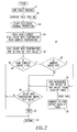
- a trip routine 40 for the ⁇ C 28 of Figure 1 is shown.
- the trip routine 40 may include one or both of an arc fault trip routine 41 and a ground fault trip routine 42.
- the start of an electronic thermal protection routine which provides a thermal overload predictive function.
- the load current current sense
- the shunt wire temperature temperature sense
- the ambient temperature are read.
- the load current is determined from the voltage of the shunt wire (R1) 8.
- the shunt wire temperature is determined from the forward voltage of the diode (D1) 18.
- the ambient temperature may be determined from a suitable ambient temperature sensor (not shown) or, optionally, is ignored. In the latter case, steps 48 and 56 are not employed.
- step 50 is executed as was discussed above.
- the "Trip Value” is preferably determined experimentally for a reference circuit (not shown) using a reference diode (not shown). Then, that experimental “trip value” is preferably adjusted at the time of manufacture of a particular circuit interrupter by measuring the forward voltage of the diode (D1) 18 at 258C. This assumes that: (1) the diode forward voltage at 258C may vary from diode to diode; and (2) the diode forward voltage temperature coefficient will be uniform from diode to diode. Also, the temperature of the shunt wire 8 at the trip point is a fixed number.
- both the bimetal and the shunt wire dissipate about the same amount of power.
- eliminating the bimetal halves the power dissipation.
- ⁇ P 6 with the NV memory 24 enables the use of the internal shunt wire (R1) 8 to sense overload and cooling off conditions.
- This ⁇ P 6 has the benefit of being able to simply measure and store ambient calibration values at the time of manufacture of the electronic circuit 4.
- a non-linear response e.g., without limitation, a lookup table
- ambient temperatures is stored in the NV memory 24 to more accurately match the UL 489 135% tripping requirements.
- separable contacts 14 are disclosed, suitable solid state separable contacts may be employed.
- the disclosed circuit breaker 2 includes a suitable circuit interrupter mechanism, such as the separable contacts 14 that are opened and closed by the operating mechanism 10, although the invention is applicable to a wide range of circuit interruption mechanisms (e.g., without limitation, solid state or FET switches; contactor contacts) and/or solid state based control/protection devices (e.g., without limitation, drives; soft-starters).
- circuit interruption mechanisms e.g., without limitation, solid state or FET switches; contactor contacts
- solid state based control/protection devices e.g., without limitation, drives; soft-starters.
- circuit interrupter such as a miniature circuit breaker 4 protective electronic circuit 6 processor, such as microprocessor ( ⁇ P) 7 arc fault circuit interrupter (AFCI) function 8 shunt wire (R1) 10 circuit breaker operating mechanism 12 trip solenoid 14 separable contacts 16 electronic ground fault protection function 17 "thermal overload” predictive function 18 diode (D1) 20 current source 22 power supply 24 nonvolatile (NV) memory 26 SCR 28 ⁇ C 30 line terminal 32 load terminal 34 line neutral terminal 36 load neutral terminal 38 non-linear ambient temperature compensation function 40 trip routine 41 arc fault trip routine 42 ground fault trip routine 43 step 44 step 45 step 46 step 48 step 52 step 54 step 56 step 58 look-up table
Abstract
Description
- This invention pertains generally to circuit interrupters and, more particularly, to circuit breakers including an electronic trip circuit and a trip actuator.
- Circuit interrupters include, for example, circuit breakers, contactors, motor starters, motor controllers, other load controllers and receptacles having a trip mechanism. Circuit breakers are generally old and well known in the art. Examples of circuit breakers are disclosed in
U.S. Patent Nos. 5,260,676 ; and5,293,522 . - Circuit breakers are used to protect electrical circuitry from damage due to an overcurrent condition, such as an overload condition or a relatively high level short circuit or fault condition. In small circuit breakers, commonly referred to as miniature circuit breakers, used for residential and light commercial applications, such protection is typically provided by a thermal-magnetic trip device. This trip device includes a bimetal which is heated and bends in response to a persistent overcurrent condition. The bimetal, in turn, unlatches a spring powered operating mechanism which opens the separable contacts of the circuit breaker to interrupt current flow in the protected power system. An armature, which is attracted by the sizable magnetic forces generated by a short circuit or fault, also unlatches, or trips, the operating mechanism.
- Miniature circuit breakers use bimetals or analog circuits to provide overload (thermal) protection. Bimetals do a good job of simulating thermal cooling of power conductors. The bimetal trips a circuit breaker when its temperature reaches a certain predetermined value. Most of today's circuit breakers are not ambient temperature compensated.
- UL 489 is a molded case circuit breaker standard that controls tripping characteristics. For a circuit breaker rated at, for example, 30 A or less, the following performance is required at three different current levels relative to the rated current:
- (1) 200%: tripping in greater than 12 seconds but less than 2 minutes; (2) 135%:
- tripping in less than 1 hour; and (3) 100%: no tripping.
- Analog circuits can simulate cooling using charge stored on a capacitor, which is simply reset to a fixed thermal level after a trip. See, for example,
U.S. Patent No. 5,418,677 . - Some analog circuits may use the temperature of an internal shunt for tripping, but this technique suffers from ambient temperature calibration issues or inaccuracies at the, above, 135% must trip setting of UL 489.
- Accordingly, there is room for improvement in circuit interrupters.
- These needs and others are met by embodiments of the invention, which provide a circuit interrupter including a processor having a thermal overload predictive function, and a shunt wire structured to measure current flowing through separable contacts for the thermal overload predictive function.
- In accordance with one aspect of the invention, a circuit interrupter comprises: separable contacts; an operating mechanism structured to open and close the separable contacts; a processor including a thermal overload predictive function; and a shunt wire in series with the separable contacts and being structured to measure current flowing through the separable contacts for the thermal overload predictive function.
- The processor may further include an arc fault circuit interrupter function, and the shunt wire may also measure the current flowing through the separable contacts for the arc fault circuit interrupter function.
- The processor may further include a non-linear ambient temperature compensation function applied to the thermal overload predictive function.
- The thermal overload predictive function may include a diode temperature sensor cooperating with the shunt wire, and a nonvolatile memory saving ambient calibration information for the diode temperature sensor.
- The diode temperature sensor may be proximate the shunt wire.
- As another aspect of the invention, a circuit interrupter comprises: separable contacts; an operating mechanism structured to open and close the separable contacts; a processor including a thermal overload predictive function and an arc fault circuit interrupter function; and a shunt wire in series with the separable contacts and being structured to measure current flowing through the separable contacts for both of the thermal overload predictive function and the arc fault circuit interrupter function.
- A full understanding of the invention can be gained from the following description of the preferred embodiments when read in conjunction with the accompanying drawings in which:
- Figure 1 is a block diagram in schematic form of a circuit breaker in accordance with an embodiment of the invention.
- Figure 2 is a flowchart of a trip routine for the microcomputer of Figure 1.
- The invention is described in association with a miniature circuit breaker, although the invention is applicable to a wide range of circuit interrupters.
- Figure 1 shows a circuit interrupter, such as a miniature circuit breaker 2, including a protective electronic circuit 4 having a processor, such as microprocessor (µP) 6. For example, for an arc fault circuit interrupter (AFCI) function 7, the protective electronic circuit 4 senses current (e.g., Ishunt = Vshunt/Rshunt) by measuring the voltage (Vshunt) across a shunt wire (R1) 8 having a known resistance (Rshunt), looks for arcing current signatures, and trips a circuit
breaker operating mechanism 10 using atrip solenoid 12 to unlatchseparable contacts 14. As another example, an electronic groundfault protection function 16 may also be included if a ground fault (GF) sensing current transformer (CT) (not shown) is added with appropriate analog signal amplification (not shown) for input by theµP 6. - The protective electronic circuit 4 and, more particularly, the
µP 6, may include one or both of an arc fault protection circuit and a ground fault protection circuit. Alternatively, other suitable trip circuit(s) may be employed. Non-limiting examples of arc fault detectors are disclosed, for instance, inU.S. Patent No. 5,224,006 , with a preferred type described inU.S. Patent No. 5,691,869 , which is hereby incorporated by reference herein. Non-limiting examples of ground fault detectors are disclosed inU.S. Patent Nos. 5,293,522 ;5,260,676 ;4,081,852 ; and3,736,468 , which are hereby incorporated by reference herein. - The example electronic circuit 4 provides a "thermal overload"
predictive function 17 through theµP 6. A temperature sensor (e.g., without limitation, a diode (D1) 18, which is driven by a suitable predetermined low level current from current source 20) is used to measure the temperature of the shunt wire (R1) 8 (with suitably close thermal coupling of the shunt wire (R1) 8 to diode (D1) 18 being employed). - A suitable power supply 22 (e.g., alternating current to direct current) supplies power to the
current source 20 and a microcomputer (µC) 28. TheµC 28 includes theµP 6 and a nonvolatile (NV)memory 24, and may also optionally include an ambient temperature sensing circuit (not shown), although such a circuit is not required. TheµP 6 drives anSCR 26 that energizes the coil of thetrip solenoid 12 to trip open theseparable contacts 14 through theoperating mechanism 10. Theseparable contacts 14 are electrically connected in series with the shunt wire (R1) 8 between aline terminal 30 and aload terminal 32. Thepower supply 22 is powered from a line-to-neutral voltage between theline terminal 30 and a lineneutral terminal 34, which is electrically connected to a loadneutral terminal 36. - For example, at the time of manufacture and test of the electronic circuit 4, the ambient temperature and the corresponding forward voltage of the diode (D1) 18, as measured by
µP 6 from the anode of diode (D1) 18 with no current in the shunt wire (R1) 8, are measured and saved in theµC NV memory 24. Diodes, such as diode (D1) 18, have a very predictable and stable negative voltage temperature coefficient (e.g., without limitation, about -2.2 mV/8C) when biased with a suitable small fixed current (e.g., without limitation, on the order of about 100 µA) from the examplecurrent source 20. - The shunt wire (R1) 8 is selected to thermally match the UL 489 protection points of 135% and 200%. The shunt wire (R1) 8 is selected to be about the same wire gauge as that of the power circuit (not shown) being protected, but generally with a relatively higher temperature insulation rating, in order that its thermal mass slows the temperature rise of that shunt. For example, when 200% current is applied, the temperature of the shunt wire (R1) 8 (and the corresponding voltage of the diode (D1) 18) reaches the trip temperature, which trips the circuit breaker 2 based upon the sensed temperature (and the corresponding sensed voltage), in about 15 seconds which is within the UL 489 limits.
- At a fixed level of current (I), the power dissipation in the
shunt wire 8 is P = (I2R) (watts), wherein R is the resistance value of theshunt wire 8. This power dissipation causes a temperature rise Tr of theshunt wire 8 wherein: (1) the "rate of temperature rise" is determined by the thermal capacitance of the shunt "Ct" [(joules = watts/second)/°C] and (2) the final steady state shunt temperature is determined by the ambient temperature and the thermal resistance "Rt" (°C/watt) from the shunt to the ambient. The temperature of the shunt is thus Tshunt = [P*Rt]*(1-e-t/RtCt) wherein: Tshunt is the temperature rise above ambient. - Ttrip is the shunt temperature rise above ambient when tripping occurs. Equations 1 and 2 show Ttrip for the ultimate (chosen or 115%) trip point and the 200% trip point, respectively.


wherein: - t@200% is chosen, for example, to be 38
seconds 
- P@I=115% is the power at 115% rated current; and
- P@I=200% is the power at 200% rated current.
- Solving Equations 1 and 2 for RtCt with Ttrip being constant yields RtCt { 95 seconds. Similarly, Equation 3 shows Ttrip for the 135% trip point.

- Using RtCt = 95 seconds and solving Equations 1 and 3 for t@135% yields RtCt { 123 seconds. Thus, the nominal trip time at 200% rated current is 38 seconds and the nominal trip time at 135% rated current is about 123 seconds.
- Any other trip equations are of the form: Ttrip = K*Irated2*[1-e-t/RtCt], wherein RtCt is the thermal time constant of the
shunt wire 8 in the ambient, K = R*PCT2Rt and PCT is the corresponding percentage of rated current. Except for the case where PCT is 115% of rated (ultimate trip point) current, where the circuit breaker 2 waits as long as it takes to trip, "t" is relatively very large and e-t/RtCt is about zero. Also, since the load current is sensed from the voltage across the shunt wire (R1) 8, the electronic overload trip can, for example, be inhibited for currents of less than about 110%. - A conventional bimetal (not shown) trips a conventional circuit breaker (not shown) at a certain temperature, To, at, for example, 115% of rated current. The heat required to get the bimetal to that temperature is shown in Equation 4.

wherein: - Rbimetal is the bimetal resistance;
- K is a gain factor (W/°C);
- To is the trip temperature (°C); and
- Tambient is the ambient temperature (°C).
- As a further example, if To is 200°C and the ambient temperature rises from 25°C to 65°C, then the circuit breaker trip current level will decrease from 115% to about 101%

µP 6 of Figure 1 knows that the load current flowing through shunt wire (R1) 8 is less than 110%, it can inhibit tripping unless the current exceeds 110% indefinitely (e.g., for several cycles). - For thermal overload conditions at about 135% of rated current, the power circuit ambient somewhat tracks the temperature rise of the shunt wire (R1) 8. Therefore, if ambient temperature compensation is to be used, then it needs to be a non-linear function desensitizing the ambient temperature effects.
- For example, the circuit breaker 2 may be hot because its load center (not shown) is located in Phoenix, Arizona on the south side of a house (not shown) on a sunny day. Hence, high ambient temperatures do not necessarily mean that the power circuit conductor (not shown), which is electrically connected to the
load terminal 32 and in series with the shunt wire (R1) 8, to be protected is also hot. Thus, ambient compensation, if used, should only be enabled at temperatures above about 40°C, which is the listed breaker operating temperature, and be just sufficient to prevent nuisance tripping. Here, the desired non-linear function is easily incorporated into the µPprotective functions 7,16 with, for example, a predetermined table lookup in theNV memory 24. - As an example, if the ambient temperature is below 40°C as measured by a circuit (not shown) either internal to the
µC 28 or on the µC circuit board, then no compensation is made. However, if the ambient temperature is 65°C, then the trip level temperature (To) may be raised by about a 20°C setpoint limit, since some of the ambient temperature rise may be due to the load current power dissipation in components other than, but also including, theshunt wire 8. - For example, the exact thermal gain of the diode (D1) 18 can be measured at the time of manufacture of the electronic circuit 4 by heating diode (D1) 18 to a known temperature above ambient temperature with a known forward current passing therethrough, reading the forward voltage, calculating the gain factor, and storing that gain factor (e.g., without limitation, k equal to about -2.2 mV/8C) in
µP NV memory 24. This is shown from Equation 5:
wherein: - TA is a predetermined ambient temperature stored in
NV memory 24 at the time of manufacture; - VA is a measured voltage across the diode (D1) 18 and stored in
NV memory 24, which measured voltage corresponds to the predetermined ambient temperature; - T1 is a measured temperature, which need not be stored in
NV memory 24; this measured temperature T1 is suitably greater than TA; and - V1 is a measured voltage across the diode (D1) 18, which need not be stored in
NV memory 24, this measured voltage V1 corresponds to the measured temperature T1. - Also, if the ambient temperature, TA, is known and the temperature sensor is a diode, such as D 1 18, then a difference voltage is needed including the forward voltage at a fixed temperature. This forward voltage, VA, at the fixed temperature, TA, is saved in the
NV memory 24 at the time of manufacture or test. In this manner, only fixed constants, VA, TA and k, possibly determined at the time of manufacture or test, need to be stored inNV memory 24. The temperature as a function of diode forward voltage is shown in Equation 6:
wherein: - VX is a measured voltage across the diode (D1) 18; and
- TX is the calculated temperature corresponding to that measured voltage.
- The temperature rise of the shunt wire (R1) 8 is proportional to the power dissipation (i.e., (Ishunt)2Rshunt) and thus VX will be related to TX or the I2R heating of the wires (i.e., the shunt wire (R1) 8 and also the power conductor or wire to be protected).
- Table 1, below, defines a set of thermal overload conditions for a circuit breaker (not shown) as defined by UL 489 (molded case circuit breaker standard) section 7.1.2 "Calibration Tests".
Table 1 Ishunt Time (t) at Ishunt value Trip? = 200% 12 seconds < t < 120 seconds yes = 200% t < 12 seconds no = 135% t < 60 minutes yes <= 110% must not trip no - Referring to Figure 2, a
trip routine 40 for theµC 28 of Figure 1 is shown. Although not required, thetrip routine 40 may include one or both of an arcfault trip routine 41 and a groundfault trip routine 42. Next, at 43, is the start of an electronic thermal protection routine, which provides a thermal overload predictive function. At 44, the load current (current sense), the shunt wire temperature (temperature sense) and the ambient temperature are read. The load current is determined from the voltage of the shunt wire (R1) 8. The shunt wire temperature is determined from the forward voltage of the diode (D1) 18. The ambient temperature may be determined from a suitable ambient temperature sensor (not shown) or, optionally, is ignored. In the latter case, steps 48 and 56 are not employed. - Next, at 45, the value "Trip Value" is set from a shunt wire temperature trip setting, as will be discussed, below. Then, at 46, it is determined if the load current is above 115% of rated current. Here, the voltage of the shunt wire (R1) 8 divided by its known resistance is compared to 115% times the predetermined rated current. Alternatively, it is determined if the voltage of the shunt wire (R1) 8 is greater than a predetermined value (115% times the predetermined rated current times the known resistance of the shunt wire 8). If this test is not met, then the routine 40 returns at 54. Otherwise, at 48, it is determined if the ambient temperature is greater than 408C. If not, then at 50, it is determined if the temperature of the shunt wire (R1) 8 as represented by the voltage of the diode (D1) 18 is greater than the "Trip Value". If so, then the trip signal is output to the SCR 26 (Figure 1) at 52, before the routine 40 returns at 54. Otherwise, the routine 40 returns at 54.
- If ambient temperature compensation is optionally employed, and if the ambient temperature is greater than 408C at 48, then a suitable incremental trip offset is added to the "Trip Value" from, for example, a look-up table 58 in NV 24 (Figure 1). The look-up table 58 maintains a suitable mapping of ambient temperature versus incremental trip offset. After either 48 or 56,
step 50 is executed as was discussed above. - In the routine 40, the "Trip Value" is preferably determined experimentally for a reference circuit (not shown) using a reference diode (not shown). Then, that experimental "trip value" is preferably adjusted at the time of manufacture of a particular circuit interrupter by measuring the forward voltage of the diode (D1) 18 at 258C. This assumes that: (1) the diode forward voltage at 258C may vary from diode to diode; and (2) the diode forward voltage temperature coefficient will be uniform from diode to diode. Also, the temperature of the
shunt wire 8 at the trip point is a fixed number. The "Trip Value" is determined fromEquations 7 and 8, as follows:
wherein: - VX is a "delta trip temperature" voltage value of the reference diode, and is assumed to be a fixed value from circuit interrupter to circuit interrupter;
- VX(135%) is the trip voltage value of the reference diode at 135% rated current and at 258C ambient for the reference diode; and
- VX(25) is the diode forward voltage at 258C ambient for the reference diode.

- VY(25) is the diode forward voltage, which may vary from circuit interrupter to circuit interrupter, at 258C ambient for a particular diode such as diode (D1) 18; and
- VY is the trip voltage value ("Trip Value") for a particular diode such as diode (D1) 18.
- The disclosed circuit breaker 2 provides a simplified and relatively more accurate calibration process than known prior circuit breakers. No mechanical moving parts are employed other than the
trip solenoid 12 and theoperating mechanism 10. This provides material and calibration cost savings and a relatively easier assembly process. The power dissipation of the prior bimetal (not shown) is no longer needed, but is replaced by the shunt wire (R1) 8 power dissipation, which may be employed for other protective functions. For example, in an arc fault circuit interrupter (AFCI), this can almost halve the load current associated circuit breaker losses (i.e., the bimetal resistance is about the same value as the resistance of the shunt wire (R1) 8 used to sense current for the AFCI function 7). In an AFCI circuit breaker with a bimetal (not shown) and a shunt wire (not shown), both the bimetal and the shunt wire dissipate about the same amount of power. Thus, eliminating the bimetal halves the power dissipation. - Using the
µP 6 with theNV memory 24 enables the use of the internal shunt wire (R1) 8 to sense overload and cooling off conditions. ThisµP 6 has the benefit of being able to simply measure and store ambient calibration values at the time of manufacture of the electronic circuit 4. Additionally, a non-linear response (e.g., without limitation, a lookup table) to ambient temperatures is stored in theNV memory 24 to more accurately match the UL 489 135% tripping requirements. Thus, if the resistance of the shunt wire (R1) 8 with an equivalent thermal time constant is used, then an electronic trip can be issued when the shunt wire (R1) 8 reaches a predetermined fixed trip temperature. - Although
separable contacts 14 are disclosed, suitable solid state separable contacts may be employed. For example, the disclosed circuit breaker 2 includes a suitable circuit interrupter mechanism, such as theseparable contacts 14 that are opened and closed by theoperating mechanism 10, although the invention is applicable to a wide range of circuit interruption mechanisms (e.g., without limitation, solid state or FET switches; contactor contacts) and/or solid state based control/protection devices (e.g., without limitation, drives; soft-starters). - While specific embodiments of the invention have been described in detail, it will be appreciated by those skilled in the art that various modifications and alternatives to those details could be developed in light of the overall teachings of the disclosure. Accordingly, the particular arrangements disclosed are meant to be illustrative only and not limiting as to the scope of the invention which is to be given the full breadth of the claims appended and any and all equivalents thereof.
-
2 circuit interrupter, such as a miniature circuit breaker 4 protective electronic circuit 6 processor, such as microprocessor (µP) 7 arc fault circuit interrupter (AFCI) function 8 shunt wire (R1) 10 circuit breaker operating mechanism 12 trip solenoid 14 separable contacts 16 electronic ground fault protection function 17 "thermal overload" predictive function 18 diode (D1) 20 current source 22 power supply 24 nonvolatile (NV) memory 26 SCR 28 µC 30 line terminal 32 load terminal 34 line neutral terminal 36 load neutral terminal 38 non-linear ambient temperature compensation function 40 trip routine 41 arc fault trip routine 42 ground fault trip routine 43 step 44 step 45 step 46 step 48 step 50 step 52 step 54 step 56 step 58 look-up table
Claims (21)
- A circuit interrupter comprising:separable contacts;an operating mechanism structured to open and close said separable contacts;a processor including a thermal overload predictive function; anda shunt wire in series with said separable contacts and being structured to measure current flowing through said separable contacts for said thermal overload predictive function.
- The circuit interrupter of Claim 1 wherein said processor further includes an arc fault circuit interrupter function; and wherein said shunt wire also measures said current flowing through said separable contacts for said arc fault circuit interrupter function.
- The circuit interrupter of Claim 1 wherein said processor further includes a non-linear ambient temperature compensation function applied to said thermal overload predictive function.
- The circuit interrupter of Claim 1 wherein said processor further includes a plurality of protective functions.
- The circuit interrupter of Claim 4 wherein said circuit interrupter is a miniature circuit breaker.
- The circuit interrupter of Claim 4 wherein said circuit interrupter is an arc fault circuit breaker.
- The circuit interrupter of Claim 4 wherein said circuit interrupter is a ground fault circuit breaker.
- The circuit interrupter of Claim 4 wherein said circuit interrupter is an arc fault / ground fault circuit breaker.
- The circuit interrupter of Claim 1 wherein said processor further includes a nonvolatile memory saving ambient calibration information for said shunt wire.
- The circuit interrupter of Claim 1 wherein said thermal overload predictive function includes a diode temperature sensor cooperating with said shunt wire, and a nonvolatile memory saving ambient calibration information for said diode temperature sensor.
- The circuit interrupter of Claim 10 wherein said diode temperature sensor is proximate said shunt wire.
- A circuit interrupter comprising:separable contacts;an operating mechanism structured to open and close said separable contacts;a processor including a thermal overload predictive function and an arc fault circuit interrupter function; anda shunt wire in series with said separable contacts and being structured to measure current flowing through said separable contacts for both of said thermal overload predictive function and said arc fault circuit interrupter function.
- The circuit interrupter of Claim 12 wherein said processor further includes a non-linear ambient temperature compensation function applied to said thermal overload predictive function.
- The circuit interrupter of Claim 12 wherein said processor further includes a plurality of protective functions.
- The circuit interrupter of Claim 14 wherein said circuit interrupter is a miniature circuit breaker.
- The circuit interrupter of Claim 14 wherein said circuit interrupter is an arc fault circuit breaker.
- The circuit interrupter of Claim 14 wherein said circuit interrupter is a ground fault circuit breaker.
- The circuit interrupter of Claim 14 wherein said circuit interrupter is an arc fault / ground fault circuit breaker.
- The circuit interrupter of Claim 12 wherein said processor further includes a nonvolatile memory saving ambient calibration information for said shunt wire.
- The circuit interrupter of Claim 12 wherein said thermal overload predictive function includes a diode temperature sensor cooperating with said shunt wire, and a nonvolatile memory saving ambient calibration information for said diode temperature sensor.
- The circuit interrupter of Claim 20 wherein said diode temperature sensor is proximate said shunt wire.
Applications Claiming Priority (1)
| Application Number | Priority Date | Filing Date | Title |
|---|---|---|---|
| US11/549,164 US7675721B2 (en) | 2006-10-13 | 2006-10-13 | Circuit interrupter including a shunt wire current sensor and a processor having a thermal overload predictive function |
Publications (2)
| Publication Number | Publication Date |
|---|---|
| EP1912238A1 true EP1912238A1 (en) | 2008-04-16 |
| EP1912238B1 EP1912238B1 (en) | 2012-10-10 |
Family
ID=38924476
Family Applications (1)
| Application Number | Title | Priority Date | Filing Date |
|---|---|---|---|
| EP07020075A Expired - Fee Related EP1912238B1 (en) | 2006-10-13 | 2007-10-12 | Circuit interrupter including a shunt wire current sensor and a processor having a thermal overload predictive function |
Country Status (6)
| Country | Link |
|---|---|
| US (1) | US7675721B2 (en) |
| EP (1) | EP1912238B1 (en) |
| AU (1) | AU2007221959B2 (en) |
| BR (1) | BRPI0714077A2 (en) |
| CA (1) | CA2606996C (en) |
| MX (1) | MX2007012789A (en) |
Cited By (2)
| Publication number | Priority date | Publication date | Assignee | Title |
|---|---|---|---|---|
| WO2011067593A3 (en) * | 2009-12-02 | 2011-11-10 | Gigle Networks Limited | Current measuring apparatus |
| WO2013178259A1 (en) * | 2012-05-30 | 2013-12-05 | Siemens Aktiengesellschaft | Overcurrent protection device |
Families Citing this family (13)
| Publication number | Priority date | Publication date | Assignee | Title |
|---|---|---|---|---|
| JP4992572B2 (en) * | 2007-06-26 | 2012-08-08 | ブラザー工業株式会社 | Power supply cutoff circuit and droplet discharge device |
| US7869178B2 (en) * | 2007-11-12 | 2011-01-11 | Honeywell International Inc. | Augmentation of ambient temperature and free convection effects in thermal circuit breaker trip curve approximations |
| JP5055177B2 (en) * | 2008-03-24 | 2012-10-24 | 矢崎総業株式会社 | Load circuit protection device |
| DE102008039334B4 (en) * | 2008-08-22 | 2016-01-14 | Airbus Defence and Space GmbH | Method and device for optimized energy management |
| US8159803B2 (en) * | 2009-12-07 | 2012-04-17 | Ward Michael J | Heat actuated interrupter receptacle |
| US20110141635A1 (en) * | 2009-12-10 | 2011-06-16 | Fabian Steven D | Thermally protected GFCI |
| BR112013001974A2 (en) * | 2010-07-26 | 2018-08-28 | Tyco Electronics Corp | controller circuit including a switching mode power converter and automatic recloser using the same |
| CN102280321A (en) * | 2011-06-10 | 2011-12-14 | 上海电机学院 | Light load overheating protection breaker |
| US9030795B2 (en) | 2012-12-21 | 2015-05-12 | Eaton Corporation | Apparatus and method of adaptive electronic overload protection |
| KR101922553B1 (en) * | 2015-11-17 | 2018-11-27 | 주식회사 엘지화학 | System and method of controlling a relay independently using a bimetal |
| DE102015121194A1 (en) * | 2015-12-04 | 2017-06-08 | Infineon Technologies Ag | Device with integrated protection course and method |
| US9728348B2 (en) * | 2015-12-21 | 2017-08-08 | Eaton Corporation | Electrical switching apparatus with electronic trip unit |
| US11004620B2 (en) * | 2019-03-18 | 2021-05-11 | Eaton Intelligent Power Limited | Circuit interrupter and method of determining contact wear based upon temperature |
Citations (10)
| Publication number | Priority date | Publication date | Assignee | Title |
|---|---|---|---|---|
| GB728774A (en) * | 1952-05-29 | 1955-04-27 | Leeds & Northrup Co | Improvements in ambient-temperature compensated device for measuring the intensity of radiant energy |
| US3736468A (en) | 1971-06-30 | 1973-05-29 | Westinghouse Electric Corp | Ground fault interrupter apparatus |
| US4081852A (en) | 1974-10-03 | 1978-03-28 | Westinghouse Electric Corporation | Ground fault circuit breaker |
| US4517543A (en) * | 1983-12-01 | 1985-05-14 | Eaton Corporation | SME overcurrent protective apparatus having ambient temperature compensation |
| US5224006A (en) | 1991-09-26 | 1993-06-29 | Westinghouse Electric Corp. | Electronic circuit breaker with protection against sputtering arc faults and ground faults |
| US5260676A (en) | 1991-03-27 | 1993-11-09 | Westinghouse Electric Corp. | Dual wound trip solenoid |
| US5293522A (en) | 1992-09-11 | 1994-03-08 | Westinghouse Electric Company | Ground fault circuit breaker with test spring/contacts directly mounted to test circuit of printed circuit board |
| US5418677A (en) * | 1990-12-28 | 1995-05-23 | Eaton Corporation | Thermal modeling of overcurrent trip during power loss |
| US5691869A (en) | 1995-06-06 | 1997-11-25 | Eaton Corporation | Low cost apparatus for detecting arcing faults and circuit breaker incorporating same |
| US6225883B1 (en) * | 2000-02-15 | 2001-05-01 | Eaton Corporation | Circuit breaker with latch and toggle mechanism operating in perpendicular planes |
Family Cites Families (12)
| Publication number | Priority date | Publication date | Assignee | Title |
|---|---|---|---|---|
| US3991391A (en) * | 1974-01-29 | 1976-11-09 | Westinghouse Electric Corporation | Circuit interrupter with electromagnetic opening means |
| US4358810A (en) * | 1981-01-21 | 1982-11-09 | Westinghouse Electric Corp. | Circuit breaker with alarm |
| US4487063A (en) * | 1983-07-11 | 1984-12-11 | General Motors Corporation | Solid state mass air flow sensor |
| DE3643221A1 (en) * | 1986-12-18 | 1988-06-30 | Braun Ag | DC CONTROLLER |
| US5436784A (en) * | 1993-08-11 | 1995-07-25 | Schweitzer Engineering Laboratories, Inc. | Motor protection relay using thermal models |
| US5459630A (en) * | 1993-09-15 | 1995-10-17 | Eaton Corporation | Self testing circuit breaker ground fault and sputtering arc trip unit |
| JP3384522B2 (en) * | 1996-07-30 | 2003-03-10 | 矢崎総業株式会社 | Switching device |
| US5835320A (en) * | 1997-05-28 | 1998-11-10 | General Electric Company | Digital circuit interrupter thermal protection circuit |
| US5936817A (en) * | 1998-05-11 | 1999-08-10 | Eaton Corporation | Electrical switching apparatus employing a circuit for selectively enabling and disabling a close actuator mechanism |
| US6137386A (en) * | 1999-08-18 | 2000-10-24 | Eaton Corporation | Circuit breaker with trip unit mounted tripping plunger and latch therefore |
| US6876532B2 (en) * | 2002-04-29 | 2005-04-05 | Eaton Corporation | Circuit interrupter trip unit |
| US7508642B2 (en) * | 2005-07-14 | 2009-03-24 | Honeywell International Inc. | Method and apparatus applying virtual Δt trip criterion in power distribution |
-
2006
- 2006-10-13 US US11/549,164 patent/US7675721B2/en active Active
-
2007
- 2007-10-11 BR BRPI0714077-0A patent/BRPI0714077A2/en not_active IP Right Cessation
- 2007-10-12 MX MX2007012789A patent/MX2007012789A/en active IP Right Grant
- 2007-10-12 AU AU2007221959A patent/AU2007221959B2/en not_active Ceased
- 2007-10-12 EP EP07020075A patent/EP1912238B1/en not_active Expired - Fee Related
- 2007-10-12 CA CA2606996A patent/CA2606996C/en active Active
Patent Citations (10)
| Publication number | Priority date | Publication date | Assignee | Title |
|---|---|---|---|---|
| GB728774A (en) * | 1952-05-29 | 1955-04-27 | Leeds & Northrup Co | Improvements in ambient-temperature compensated device for measuring the intensity of radiant energy |
| US3736468A (en) | 1971-06-30 | 1973-05-29 | Westinghouse Electric Corp | Ground fault interrupter apparatus |
| US4081852A (en) | 1974-10-03 | 1978-03-28 | Westinghouse Electric Corporation | Ground fault circuit breaker |
| US4517543A (en) * | 1983-12-01 | 1985-05-14 | Eaton Corporation | SME overcurrent protective apparatus having ambient temperature compensation |
| US5418677A (en) * | 1990-12-28 | 1995-05-23 | Eaton Corporation | Thermal modeling of overcurrent trip during power loss |
| US5260676A (en) | 1991-03-27 | 1993-11-09 | Westinghouse Electric Corp. | Dual wound trip solenoid |
| US5224006A (en) | 1991-09-26 | 1993-06-29 | Westinghouse Electric Corp. | Electronic circuit breaker with protection against sputtering arc faults and ground faults |
| US5293522A (en) | 1992-09-11 | 1994-03-08 | Westinghouse Electric Company | Ground fault circuit breaker with test spring/contacts directly mounted to test circuit of printed circuit board |
| US5691869A (en) | 1995-06-06 | 1997-11-25 | Eaton Corporation | Low cost apparatus for detecting arcing faults and circuit breaker incorporating same |
| US6225883B1 (en) * | 2000-02-15 | 2001-05-01 | Eaton Corporation | Circuit breaker with latch and toggle mechanism operating in perpendicular planes |
Cited By (3)
| Publication number | Priority date | Publication date | Assignee | Title |
|---|---|---|---|---|
| WO2011067593A3 (en) * | 2009-12-02 | 2011-11-10 | Gigle Networks Limited | Current measuring apparatus |
| US8884607B2 (en) | 2009-12-02 | 2014-11-11 | Broadcom Corporation | Current measuring apparatus |
| WO2013178259A1 (en) * | 2012-05-30 | 2013-12-05 | Siemens Aktiengesellschaft | Overcurrent protection device |
Also Published As
| Publication number | Publication date |
|---|---|
| BRPI0714077A2 (en) | 2009-06-16 |
| US20080088991A1 (en) | 2008-04-17 |
| AU2007221959A1 (en) | 2008-05-01 |
| CA2606996A1 (en) | 2008-04-13 |
| EP1912238B1 (en) | 2012-10-10 |
| MX2007012789A (en) | 2009-02-17 |
| AU2007221959B2 (en) | 2012-04-05 |
| CA2606996C (en) | 2015-07-07 |
| US7675721B2 (en) | 2010-03-09 |
Similar Documents
| Publication | Publication Date | Title |
|---|---|---|
| EP1912238B1 (en) | Circuit interrupter including a shunt wire current sensor and a processor having a thermal overload predictive function | |
| US7400482B2 (en) | Circuit breaker and method for sensing current indirectly from bimetal voltage and determining bimetal temperature and corrected temperature dependent bimetal resistance | |
| EP3161837B1 (en) | Thermal trip assembly and circuit interrupter including the same | |
| US6876532B2 (en) | Circuit interrupter trip unit | |
| JP2003100196A (en) | Electronic circuit breaker | |
| EP3271933B1 (en) | Electronic trip units powered by current transformers and circuit breakers comprising the same | |
| EP3161849B1 (en) | Circuit interrupter including thermal trip assembly and printed circuit board rogowski coil | |
| US5966281A (en) | Circuit breaker with thermal sensing unit | |
| US9030795B2 (en) | Apparatus and method of adaptive electronic overload protection | |
| US20050219032A1 (en) | Method and apparatus for providing electrical protection to a protected circuit | |
| Aronstein | Temperature sensitivity of residential molded case circuit breakers | |
| US10622801B2 (en) | Circuit interrupter with temperature compensation and method of operating a circuit interrupter | |
| US5999385A (en) | Ground fault circuit breaker | |
| CN116648838A (en) | Protection switch device and method | |
| Strobel | Equipment and Apparatus Circuit Protection | |
| Lagree et al. | Un-powered thermal memory protection for circuit breakers |
Legal Events
| Date | Code | Title | Description |
|---|---|---|---|
| PUAI | Public reference made under article 153(3) epc to a published international application that has entered the european phase |
Free format text: ORIGINAL CODE: 0009012 |
|
| AK | Designated contracting states |
Kind code of ref document: A1 Designated state(s): AT BE BG CH CY CZ DE DK EE ES FI FR GB GR HU IE IS IT LI LT LU LV MC MT NL PL PT RO SE SI SK TR |
|
| AX | Request for extension of the european patent |
Extension state: AL BA HR MK RS |
|
| 17P | Request for examination filed |
Effective date: 20081014 |
|
| 17Q | First examination report despatched |
Effective date: 20081117 |
|
| AKX | Designation fees paid |
Designated state(s): DE FR GB IT |
|
| GRAP | Despatch of communication of intention to grant a patent |
Free format text: ORIGINAL CODE: EPIDOSNIGR1 |
|
| GRAS | Grant fee paid |
Free format text: ORIGINAL CODE: EPIDOSNIGR3 |
|
| GRAA | (expected) grant |
Free format text: ORIGINAL CODE: 0009210 |
|
| AK | Designated contracting states |
Kind code of ref document: B1 Designated state(s): DE FR GB IT |
|
| REG | Reference to a national code |
Ref country code: GB Ref legal event code: FG4D |
|
| REG | Reference to a national code |
Ref country code: DE Ref legal event code: R096 Ref document number: 602007025964 Country of ref document: DE Effective date: 20121213 |
|
| PLBE | No opposition filed within time limit |
Free format text: ORIGINAL CODE: 0009261 |
|
| STAA | Information on the status of an ep patent application or granted ep patent |
Free format text: STATUS: NO OPPOSITION FILED WITHIN TIME LIMIT |
|
| 26N | No opposition filed |
Effective date: 20130711 |
|
| REG | Reference to a national code |
Ref country code: DE Ref legal event code: R097 Ref document number: 602007025964 Country of ref document: DE Effective date: 20130711 |
|
| PGFP | Annual fee paid to national office [announced via postgrant information from national office to epo] |
Ref country code: GB Payment date: 20130925 Year of fee payment: 7 |
|
| PGFP | Annual fee paid to national office [announced via postgrant information from national office to epo] |
Ref country code: FR Payment date: 20130924 Year of fee payment: 7 Ref country code: DE Payment date: 20131031 Year of fee payment: 7 |
|
| PGFP | Annual fee paid to national office [announced via postgrant information from national office to epo] |
Ref country code: IT Payment date: 20131022 Year of fee payment: 7 |
|
| REG | Reference to a national code |
Ref country code: DE Ref legal event code: R119 Ref document number: 602007025964 Country of ref document: DE |
|
| GBPC | Gb: european patent ceased through non-payment of renewal fee |
Effective date: 20141012 |
|
| PG25 | Lapsed in a contracting state [announced via postgrant information from national office to epo] |
Ref country code: GB Free format text: LAPSE BECAUSE OF NON-PAYMENT OF DUE FEES Effective date: 20141012 Ref country code: DE Free format text: LAPSE BECAUSE OF NON-PAYMENT OF DUE FEES Effective date: 20150501 |
|
| REG | Reference to a national code |
Ref country code: FR Ref legal event code: ST Effective date: 20150630 |
|
| PG25 | Lapsed in a contracting state [announced via postgrant information from national office to epo] |
Ref country code: FR Free format text: LAPSE BECAUSE OF NON-PAYMENT OF DUE FEES Effective date: 20141031 Ref country code: IT Free format text: LAPSE BECAUSE OF NON-PAYMENT OF DUE FEES Effective date: 20141012 |