EP1913876A1 - Treatment device for endoscope - Google Patents
Treatment device for endoscope Download PDFInfo
- Publication number
- EP1913876A1 EP1913876A1 EP05770426A EP05770426A EP1913876A1 EP 1913876 A1 EP1913876 A1 EP 1913876A1 EP 05770426 A EP05770426 A EP 05770426A EP 05770426 A EP05770426 A EP 05770426A EP 1913876 A1 EP1913876 A1 EP 1913876A1
- Authority
- EP
- European Patent Office
- Prior art keywords
- treatment tool
- distal end
- open
- endoscope
- liquid
- Prior art date
- Legal status (The legal status is an assumption and is not a legal conclusion. Google has not performed a legal analysis and makes no representation as to the accuracy of the status listed.)
- Withdrawn
Links
Images


Classifications
-
- A—HUMAN NECESSITIES
- A61—MEDICAL OR VETERINARY SCIENCE; HYGIENE
- A61B—DIAGNOSIS; SURGERY; IDENTIFICATION
- A61B17/00—Surgical instruments, devices or methods, e.g. tourniquets
-
- A—HUMAN NECESSITIES
- A61—MEDICAL OR VETERINARY SCIENCE; HYGIENE
- A61B—DIAGNOSIS; SURGERY; IDENTIFICATION
- A61B10/00—Other methods or instruments for diagnosis, e.g. instruments for taking a cell sample, for biopsy, for vaccination diagnosis; Sex determination; Ovulation-period determination; Throat striking implements
- A61B10/02—Instruments for taking cell samples or for biopsy
- A61B10/06—Biopsy forceps, e.g. with cup-shaped jaws
-
- A—HUMAN NECESSITIES
- A61—MEDICAL OR VETERINARY SCIENCE; HYGIENE
- A61B—DIAGNOSIS; SURGERY; IDENTIFICATION
- A61B17/00—Surgical instruments, devices or methods, e.g. tourniquets
- A61B17/12—Surgical instruments, devices or methods, e.g. tourniquets for ligaturing or otherwise compressing tubular parts of the body, e.g. blood vessels, umbilical cord
- A61B17/128—Surgical instruments, devices or methods, e.g. tourniquets for ligaturing or otherwise compressing tubular parts of the body, e.g. blood vessels, umbilical cord for applying or removing clamps or clips
- A61B17/1285—Surgical instruments, devices or methods, e.g. tourniquets for ligaturing or otherwise compressing tubular parts of the body, e.g. blood vessels, umbilical cord for applying or removing clamps or clips for minimally invasive surgery
-
- A—HUMAN NECESSITIES
- A61—MEDICAL OR VETERINARY SCIENCE; HYGIENE
- A61B—DIAGNOSIS; SURGERY; IDENTIFICATION
- A61B17/00—Surgical instruments, devices or methods, e.g. tourniquets
- A61B17/34—Trocars; Puncturing needles
-
- A—HUMAN NECESSITIES
- A61—MEDICAL OR VETERINARY SCIENCE; HYGIENE
- A61M—DEVICES FOR INTRODUCING MEDIA INTO, OR ONTO, THE BODY; DEVICES FOR TRANSDUCING BODY MEDIA OR FOR TAKING MEDIA FROM THE BODY; DEVICES FOR PRODUCING OR ENDING SLEEP OR STUPOR
- A61M31/00—Devices for introducing or retaining media, e.g. remedies, in cavities of the body
-
- A—HUMAN NECESSITIES
- A61—MEDICAL OR VETERINARY SCIENCE; HYGIENE
- A61B—DIAGNOSIS; SURGERY; IDENTIFICATION
- A61B1/00—Instruments for performing medical examinations of the interior of cavities or tubes of the body by visual or photographical inspection, e.g. endoscopes; Illuminating arrangements therefor
- A61B1/012—Instruments for performing medical examinations of the interior of cavities or tubes of the body by visual or photographical inspection, e.g. endoscopes; Illuminating arrangements therefor characterised by internal passages or accessories therefor
- A61B1/018—Instruments for performing medical examinations of the interior of cavities or tubes of the body by visual or photographical inspection, e.g. endoscopes; Illuminating arrangements therefor characterised by internal passages or accessories therefor for receiving instruments
-
- A—HUMAN NECESSITIES
- A61—MEDICAL OR VETERINARY SCIENCE; HYGIENE
- A61B—DIAGNOSIS; SURGERY; IDENTIFICATION
- A61B17/00—Surgical instruments, devices or methods, e.g. tourniquets
- A61B17/34—Trocars; Puncturing needles
- A61B17/3478—Endoscopic needles, e.g. for infusion
-
- A—HUMAN NECESSITIES
- A61—MEDICAL OR VETERINARY SCIENCE; HYGIENE
- A61B—DIAGNOSIS; SURGERY; IDENTIFICATION
- A61B17/00—Surgical instruments, devices or methods, e.g. tourniquets
- A61B17/28—Surgical forceps
- A61B17/29—Forceps for use in minimally invasive surgery
- A61B2017/2926—Details of heads or jaws
- A61B2017/2931—Details of heads or jaws with releasable head
-
- A—HUMAN NECESSITIES
- A61—MEDICAL OR VETERINARY SCIENCE; HYGIENE
- A61B—DIAGNOSIS; SURGERY; IDENTIFICATION
- A61B2217/00—General characteristics of surgical instruments
- A61B2217/002—Auxiliary appliance
- A61B2217/005—Auxiliary appliance with suction drainage system
-
- A—HUMAN NECESSITIES
- A61—MEDICAL OR VETERINARY SCIENCE; HYGIENE
- A61B—DIAGNOSIS; SURGERY; IDENTIFICATION
- A61B2217/00—General characteristics of surgical instruments
- A61B2217/002—Auxiliary appliance
- A61B2217/007—Auxiliary appliance with irrigation system
Definitions
- the present invention relates to a treatment tool for an endoscope used while being inserted in a channel of the endoscope.
- Hemorrhaging occasionally occurs when accomplishing treatment with an endoscope in the mucous membrane of the inner wall of digestive organs and the like.
- a treatment tool for an endoscope having a liquid conduit is occasionally used.
- the treatment tool for the endoscope is forceps which is a set of treatment pieces attached by pins so as to freely open and close
- a liquid conduit is arranged on the axis line of the flexible sheath.
- a liquid conduit passes between the two pins provided to each of the treatment pieces, and opens in the center of the front surface of the installation spacer. After opening the set of treatment pieces to start the transport of water, water is sprayed toward the front from between the treatment pieces.
- Patent Document 1 Japanese Unexamined Patent Application, First Publication No. 2004-275548
- the forceps are high-frequency forceps
- hemostasis is occasionally accomplished while the treatment pieces are closed.
- the treatment pieces necessarily need not be opened.
- water cannot be transported forward.
- the present invention has the object of facilitating liquid transport irrespective of the open or close state of the distal end.
- the present invention is an treatment tool for a endoscope characterized in that it comprises a treatment tool insertion portion to be inserted into a channel of the endoscope; an open/close member support portion formed in a distal end of the treatment tool insertion portion; an open/close member which is freely supported so as to be opened or closed and treats a target site; a liquid conduit which transports a liquid to a target site, liquid conduit being provided on an outside of the open/close member in a direction orthogonal to a lengthwise direction of the open/close member, and comprising at least one distal end aperture which opens toward the distal end direction of the open/close member support portion, the liquid conduit transports.
- the present invention is characterized in that the distal end aperture of the liquid conduit is provided in a position which has shifted approximately 90 degrees around the axis line of the treatment tool insertion portion relative to an open/close direction of the open/close member.
- the present invention is characterized in that the liquid conduit is provided on an outside of the treatment tool insertion portion.
- the liquid conduit is arranged outside of the treatment tool insertion portion, the structure of the device is simplified.
- the present invention is characterized in that the treatment tool for the endoscope is biopsy forceps, or high-frequency forceps, or a clip.
- the treatment tool for the endoscope is high-frequency forceps, biopsy forceps, or a clip
- liquid or a hemostat is transported to the liquid conduit to flush the hemorrhage.
- the present invention is an treatment tool for a endoscope characterized in that it comprises a treatment tool insertion portion to be inserted into a channel of the endoscope; an open/close member support portion formed in a distal end of the treatment tool insertion portion; an open/close member which is freely supported so as to be opened or closed and treats a target site; a transmission member which is coupled to the open/close member passing through a hole formed in the open/close member support portion from the treatment tool insertion portion in order to transmit a driving force on the open/close member side; and a liquid transport flow path which is provided within the treatment tool insertion portion and transports a liquid to a target site, the liquid transport flow path having a flow path area larger than a flow path area formed between the hole and transmission member.
- the present invention adopts the above-described structure, it is assured that liquid transport to the target site is accomplished corresponding to the state of use. Accordingly, hemostasis is quickly performed, enabling confirmation of the bleeding site.
- FIG. 1 A schematic structure of an endoscope system which includes the treatment tool for the endoscope of the present embodiment is shown in FIG 1 .
- the endoscope system comprises an endoscope 1, high-frequency forceps (treatment tool for endoscope) 3 inserted into the forceps channel 2 of the endoscope 1, and an endoscope body 5 connected via a universal code 4 to the endoscope 1.
- the endoscope 1 comprises a flexible insertion portion 6 inserted into the living body, and an operation portion 7 connected to the proximal end (outside of the body) of the insertion portion 6, and the universal code 4.
- a flexible bend portion 8 To the distal end of the insertion portion 6 is connected a flexible bend portion 8, to the distal end of which is connected a distal end cover 9.
- a photographic image unit not shown in the drawing, for observing the inside of the body, and an illumination unit which provides illumination light.
- an aperture of the forceps channel 2 On the distal end surface of the distal end cover 9 is formed an aperture of the forceps channel 2.
- the forceps channel 2 comprises a forceps aperture 2a on the side of the operation portion 7, which communicates to the inside and outside of the body.
- a forceps stopper 10 To forceps aperture 2a is attached a forceps stopper 10.
- the operation portion 7 comprises, other than the forceps aperture 2a, plural switches 11 and plural operation knobs 12.
- On the switches 11 is provided a switch to record an image photographed by the photographic unit, or a switch to change the illumination or the like. Signals of each switch is sent to the endoscope main body 5 via the universal cable.
- the operation knobs 12 include a knob for directing the flexible bend portion 8 to a certain direction.
- the endoscope main body 5 is provided with a unit for processing or display of an image photographed by the endoscope 1, an illumination light source for photography, or the like.
- the high-frequency forceps 3 are energy forceps that are capable of accomplishing hemostasis by burning the blood vessels W2, exposed by a cross section, the mucous membrane tissue W3 on the its periphery, or the submucosal layer tissue W4 and the like, made by an incision of the inner wall W1 of the digestive organs.
- the high-frequency forceps 3 comprise a treatment portion 22 provided in the distal end of the flexible treatment tool insertion portion 21 and two operation wires 23a and 23b (transmission member, see FIG. 3 ) which accomplish an open/close operation of the treatment portion 22, and a treatment tool operation portion 24 provided at the proximal end of a treatment tool insertion portion 21.
- the treatment tool insertion portion 21 comprises an inner sheath in the form of a coil 25. Inside of the inner sheath 25 is formed a liquid conduit 26 in which liquid flows along the inner sheath 25. Within the liquid conduit 26 are inserted operation wires 23a and 23b. The outside of the inner sheath 25 is covered with a tubelike outer sheath 27 formed from an insulation member. By this means, the inner sheath 25 is insulated by the outer sheath 27 from its outside.
- treatment portion 22 comprises a distal end cover (open/close member support portion) 30 secured to the distal end of the treatment tool insertion portion 21, and a set of forceps cups (open/close members) 32a and 32b, supported so as to freely rotate by the pin 31 of the cover 30.
- the distal end cover has an approximate cylindrical shape, and comprises a liquid transport lumen 33 which extends from the proximal end where it is attached to the treatment tool insertion portion 21 to the distal end which faces the hemorrhage site.
- the liquid transport lumen 33 is a liquid conduit which passes through along the lengthwise direction of the distal end cover 3.
- On the distal end surface of the distal end cover is formed a distal end aperture 33a of the liquid transport lumen 33.
- a single distal end aperture 33a is arranged on the outside in the diameter direction orthogonal to the lengthwise direction of the forceps cups 32a and 32b, and the cover 30, which is open toward the tip (distal end).
- a slit 34 is provided in parallel to the liquid transport lumen 33.
- the slit 34 is a groove formed facing the proximal end side of the distal end the cover 30 from the distal end side of the distal end the cover 30.
- two insertion through-holes 35 are provided in the wall 30a of the proximal end side of the distal end the cover 30, approximately parallel to the axis line of the distal end the cover 30.
- the insertion through-hole 35 communicates to the treatment tool insertion portion 21 and the slit 34.
- one of the operation wires 23a or 23b is inserted so as to be capable of advancing or retreating.
- Each of the forceps cup 32a, 32b are arranged facing and along the slit 34 provided in the distal end the cover 30.
- the forceps cups 32a and 32b comprise cups 36a and 36b, and arms 37a and 37b extendingly extends from the proximal end of the cups 36a and 36b rearward (toward the treatment tool insertion portion 21 side).
- the cups 36a and 36b comprise indentations 38a and 38b on the surfaces facing each other.
- the forceps surface 39a which forms an outer periphery of the indentation 38a connects to another cup 36b, and plural grooves 40 are provided with a predetermined spacing.
- the forceps surface 39b which forms the outer periphery of the indentation 38b connects to another cup 36a, and plural grooves 40 are provided with a predetermined spacing.
- the arm 37a of forceps cup 32a extends rearward from the proximal end of the cup 36a.
- a hole 48a is formed in the rear portion of the arm 37a, and engages with the distal end of the operation wire 23a.
- the distal end of operation wire 23b is rotatably supported by a pin 31 between the end of the arm 37a and the cup 36a.
- a hole 48b is formed in the rear portion of the arm 37b, and engages with the distal end of the operation wire 23b.
- the predetermined position of arm 37b is supported by the pin 31 (see FIG. 3 ) so as to freely rotate.
- the forceps cups 32a and 32b rotate about the pin 31.
- Each of the pins 31, the arms 37a and 37b, and each distal end of the operation wires 23a and 23b forms a link mechanism which opens and closes the set of the forceps cups 32a and 32b.
- operation wire 23a and operation wire 23b respectively engage with forceps cup 32a and forceps cup 32b, passing through the insertion through-hole 35 of the distal end the cover 30.
- Each operation wire 23a and 23b is covered with a sheath having an insulating conductive material.
- the distal ends of the operation wires 23a and 23b are electrically connected to the forceps cups 32a and 32b.
- the proximal end of the operation wires 23a and 23b pass through the treatment tool insertion portion 21, and are drawn out to the treatment tool operation portion 24, and connected to the handle 41 of the treatment tool operation portion 24.
- the treatment tool operation portion 24 comprises an operation component main body 42 and a slidable handle 41 relative to the operation component main body 42.
- a finger ring 43 On the proximal end of the operation component main body 42 is provided a finger ring 43. In the distal end side of the operation component main body 42 is provided a lure cock 44. The inner passage of the lure cock 44 passes within the operation component main body 42 and communicates to a liquid conduit 26 (see FIG. 3 ).
- a slide groove 45 On the finger ring 43 side of the operation component main body 42 is formed a slide groove 45 along the lengthwise direction of the operation component main body 42. In slide groove 45 a handle 41 is inserted and mounted so as to be freely slidable. On the handle 41 are secured the operation wires 23a and 23b which pass through the operation component main body 42.
- the handle 41 is provided with finger holes 46a and 46b on which the operator can place his fingers, and a terminal 47.
- the terminal 47 is electrically connected to the operation wires 23a and 23b.
- a high-frequency electric power source 49 is connected to the terminal 47 (see FIG. 1 ), the electric power of which can be conducted to the set of the forceps cups 32a and 32b.
- a liquid supply device (not shown) in which a liquid is stored.
- a syringe or a liquid pump may be used.
- the liquid water, physiological saline solution, a hemostat, or a stain solution and the like may be used.
- the high-frequency forceps 3 are inserted into the channel 2 of the endoscope 1, and the terminal 47 is connected to the high-frequency electric power source 49.
- the distal ends of the high-frequency forceps 3 are positioned in a close proximity to the periphery of the hemorrhage site (for example, the blood vessel W2 shown in FIG. 1 ).
- the insertion portion 6 of the endoscope 1 is bent so that the distal end side of the distal end the cover 30 of the high-frequency forceps 3 faces the hemorrhage site.
- the liquid in the lure cock 44 of the treatment tool operation portion is connected to a syringe in which a liquid is stored, and the liquid delivered from the syringe to the liquid conduit 26 is sprayed facing the hemorrhage site through the distal end aperture 33a from the liquid transport lumen 33 of the treatment unit 22, being led to the treatment unit 22 through a liquid conduit 26, flushing the blood on the periphery of the hemorrhage site.
- the handle 41 of the treatment tool operation portion 24 is slid, opening the set of the forceps cups 32a and 32b.
- the operation wires 23a and 23b are advanced toward the site of the hemorrhage.
- the arms 37a and 37b supported by the pin 31 to the distal end the cover 30 move so as to be space apart in the direction approximately orthogonal to the lengthwise direction of the treatment units 22.
- Each of the forceps cups 32a and 32b rotate about the pin 31, increasing the distance between each of the forceps surfaces 39a and 39b.
- the entire frequency forceps 3 are advanced.
- the handle 41 of the treatment tool operation portion 24 is drawn back.
- the operation wires 23a and 23b are withdrawn, and the arms 37a and 37b are drawn closer.
- the forceps cups 32a and 32b rotate about the pin 31, closing the set of the forceps cups 32a and 32b.
- the tips of the sections of the blood vessels W2 are fitted into the indentations 38a and 38b of the forceps cups 32a and 32b, and do not make contact with the forceps surfaces 39a and 39b.
- the submucosal layer tissue W4 making contact with the forceps surfaces 39a and 39b is cauterized such that the blood vessels W2 are included therein.
- liquid can be sprayed in a direction approximately parallel to the direction in which the set of forceps 32a and 32b extend from the liquid transport lumen. Accordingly, while the high-frequency forceps 3 are supported in a state in which they are inserted into the endoscope 1, liquid can be flushed on the periphery of the hemorrhage, the position of which can be accurately confirmed. Since the lengthwise direction of the liquid transport lumen and the direction in which the set of the forceps cups 32a and 32b extend are approximately parallel, the position of spraying the liquid can be identified, and hemostasis can be quickly and simply accomplished.
- liquid conduit and the liquid transport lumen 33 are provided in the treatment tool insertion portion 21 of the high-frequency forceps 3 and the distal end the cover 30 as a unit, while washing the affected area using the liquid transport, or immediately after washing, hemostasis can be accomplished with radio waves, which facilitate the procedures. Since the liquid transport lumen 33 and the set of the forceps cups 32a and 32b are arranged in different positions, the structure of the device can be simplified.
- the liquid transport lumen 33 does not interfere with opening and closing of the forceps cups 32a and 32b. There is also no narrowing of the field of vision.
- the clearance (flow path area) at the time the operation wires pass through the wall 30a of the distal end the cover 30 is sufficiently small compared to the flow path area of the liquid transport lumen 33. Accordingly, even if the insertion through-hole 35 of the operation wires 23a and 23b is not of watertight construction, leakage of the liquid can be prevented.
- high-frequency forceps 80 are provided on a treatment unit 81 attached to the distal end of the flexible treatment tool insertion portion 21.
- a treatment tool operation portion 83 To the proximal end of the treatment tool insertion portion 21 is attached a treatment tool operation portion 83.
- a liquid conduit 84 which transports sprayed liquid toward the site of the hemorrhage.
- a set of the forceps cups 32a and 32b are supported so as to be freely rotated and face a distal end cover (open/close member support portion) 85.
- the forceps cups 32a and 32b have the same construction as that of the first embodiment.
- the treatment unit 81 is constructed so as to freely rotate about an unshown pin, by means of a link mechanism formed from the arms 37a and 37b and the operation wires 23a and 23b.
- the operation wires 23a and 23b are secured to the handle 41 of the treatment tool operation portion 83, passing through the inside of the distal end cover 85 and the treatment tool insertion portion 21.
- a part of the outer periphery of the distal end cover 85 is indented.
- the distal end of a liquid conduit 84 is secured to the indentation 85a.
- the indentation 85a is attached along the length of the distal end cover 85 in a position which is approximately orthogonal to the open/close direction of the distal end of the set of the forceps cups 32a and 32b.
- a single distal end aperture 84 is arranged on the outside in the diameter direction orthogonal to the lengthwise direction of the forceps cups 32a and 32b, and distal end cover 85, which is open toward the tip (distal end).
- liquid conduit 84 is flexible, at least the part secured to the outer surface of the external sheath 27.
- the proximal end of the liquid conduit 84 is secured to the operation main body 86 of the treatment tool operation portion 83.
- To the proximal end of the liquid conduit 84 is attached the lure cock 44 to which a syringe can be connected.
- the outer surface of the operation portion main body 86 of the treatment tool operation portion 83 is secured to the liquid conduit 84.
- the operation portion main body 86 is directly connected to the liquid conduit 84 and the lure cock 44.
- Other construction is the same as that of the first embodiment.
- the treatment unit 81 is used while being inserted in the channel 2 of the endoscope 1.
- the distal end of the distal end cover 85 is directed to the hemorrhage site side, and liquid is sent from a syringe.
- the liquid sent from the syringe is sprayed from the distal end of the liquid conduit 84, flushing the blood on the periphery of the hemorrhage.
- the operation wires 23a and 23b are advanced or withdrawn, and the hemorrhage site and its periphery is sandwiched between the set of the forceps cups 32a and 32b.
- High frequency current is applied from the high frequency electric power source 49, and the submucosal layer tissue W4 in contact with the forceps surfaces 39a and 39b are cauterized while the blood vessels W2 is included therein
- liquid conduit 84 is arranged on the outside of the treatment unit 81 and the treatment tool insertion portion 21, liquid transport and hemostasis can be accomplished with simple construction. Other effects are the same as those of the first embodiment.
- the treatment tool for the endoscope is biopsy forceps.
- the same symbols are applied to the same construction elements as those of the first embodiment. Explanations which are repetitive to those of the first embodiment are omitted.
- the biopsy forceps 91 comprise a treatment tool insertion portion 92 which is flexible and elongated.
- a sheath 93 of the treatment tool insertion portion 92 is hollow.
- the lumen of the sheath 93 forms the liquid conduit 94.
- To the distal end of the sheath 93 is attached an integral the open/close member support portion 95.
- the open/close member support portion 95 is attached crossing the diameter direction, and forms an indentation which has the slit 96.
- a liquid conduit 94 extends approximately in parallel to the axis line of the sheath 93.
- the distal end of the liquid conduit 94 branches into two liquid transport branch pipe passages which sandwich the open/close member support portion 95, and form distal end apertures 97 on the surface of the sheath 93.
- the two distal end apertures 97 are arranged on the outside diameter orthogonal to the lengthwise direction of the biopsy cups 99 and the open/close support member 95, and are open toward the tip (distal end). As shown in FIG. 9 , the distal end apertures 97 have a shape of a circle a part of which is clipped by the open/close member support portion 95.
- the pin 98 crosses the slit 96 in a direction orthogonal to the axis line of the sheath 93.
- biopsy cups 99 being a set of open/close members are freely supported so as to be opened or closed in the open/close member support portion 95.
- the biopsy cups 99 comprise arms 99a supported by a pin 98. At the tip of the arms 99a, cups 99b protrude closer to the distal end than the sheath 93. Each cup 99b has indentation (not shown) which faces each other. The size of the set of cups 99b in the closed state is less than the outer diameter of the sheath 93.
- the width of the cups 99b in the direction orthogonal to the direction of opening and closing thereof is narrower than the spacing between the distal end apertures 97.
- the biopsy cups 99 are arranged so as to be sandwiched by the two apertures 97.
- To the proximal end of the arms 99a of the biopsy cups 99 are coupled operation wires 100.
- the operation wires 100 are pulled within a hollow the sheath 93 passing through the insertion through-hole 101 of the open/close member support portion 95, and are coupled to an un-shown treatment tool operation portion.
- the treatment tool operation portion is constructed so as to exclude the terminal 47 from the treatment tool operation portion 24 shown in FIG. 1 .
- An insertion through-hole 101 communicates to the liquid conduit 94 and the slit 96.
- the flow path area of the gap at the time when the operation wires are passed through the insertion through-hole 101 is sufficiently smaller than the flow path area of the liquid transport branch pipe path 94a and the distal end aperture 97.
- the biopsy forceps 91 are inserted into the endoscope 1 (see FIG. 1 ), and the biopsy cups 99 are placed in close proximity to a target site.
- a physiological saline solution is injected from the lure cock 44, and is sprayed from the distal end aperture 97 through the liquid conduit 94.
- the physiological saline solution reaches the target site without being shielded by the biopsy cups 99, and the hemorrhage is flushed.
- the handle 41 after opening the set of the biopsy forceps 91, the entire treatment tool insertion portion 92 is advanced, and the biopsy cups 99 are pressed against the target site. Subsequently, after closing the biopsy cups 99 and sandwiching the target site, the entire treatment tool insertion portion 92 is withdrawn to the rear, and pulled off the target site to collect it.
- the biopsy forceps 91 may have distal end apertures 97 defined in a position distant from the moving range when the biopsy cups 99 is opened or closed, the biopsy cups 99 may be opened or closed while spraying a physiological saline solution.
- a hemostat is injected from the lure cock 44, and is sprayed from the distal end apertures 97, reaching the hemorrhage site without being shielded by the biopsy cups 99.
- liquid transport can be accomplished while the set of biopsy cups 99 are closed, and the hemorrhage can be flushed prior to treatment. Accordingly, confirmation of the target site is facilitated. Since it is possible to accomplish liquid transport while the set of biopsy cups 99 are closed, the hemostat can be dispersed after collecting the body tissue of the target site, after which hemostasis can be quickly accomplished.
- liquid transport By accomplishing liquid transport while the biopsy cups 99 are closed, since a large field of vision can be assured, liquid transport can be reliably realized. Since liquid transport can be accomplished when the biopsy cups 99 are opened or closed, a procedure can be quickly performed. Since the two distal end apertures 97 are defined so as to sandwich the biopsy cups 99, liquid transport can be accomplished to a broad region which includes the target site.
- the amount of liquid flowing from the insertion opening 101 is made to be extremely small, with an assured amount of liquid flowing from the distal end openings 97, assuring hemostasis and the ability to flush the hemorrhage. Since the cups 99b are positioned closer to the distal end side than the distal end openings 97a, a biopsy can be quickly performed. Other advantages are the same as those of the first embodiment.
- the treatment tool for the endoscope may be high-frequency forceps having the structure described in the third embodiment.
- Physiological saline solution can be transported from the distal end aperture 97 and cauterization may be performed after confirming the hemorrhage site.
- the treatment tool for the endoscope is a ligature tool on which an open/close type clip is mounted.
- the same symbols are applied as for those of the same elements in the first embodiment, and explanations which would be repetitive those of the first embodiment are omitted.
- the ligature tool 110 comprises a treatment tool insertion portion 111 inserted in the treatment tool channel of the endoscope.
- the treatment tool insertion portion 111 comprises an external sheath 112 which is flexible and elongated, and an internal sheath 113 which can be freely inserted to or withdrawn from the external sheath 112.
- the external sheath 112 has a hole 114, in the center of which is inserted into the internal sheath 113.
- four liquid conduits 115 extend to the outer periphery of the hole 1 14, approximately in parallel to the axis line. Accordingly, as shown in FIG. 10 , the distal end 116 of the liquid conduit 115 formed on the distal end surface of the outer sheath 112 is arranged so as to enclose hole 114.
- the inner sheath 113 is formed from a tightly winded coil sheath.
- the periphery of the distal end aperture of the inner sheath 113 is a stopper 117 having a reduced inner diameter.
- An operation wire 118 is inserted so as to freely advance into or be withdrawn from within the inner sheet 113.
- the distal end of the operation wire 118 has an enlarge diameter part 118a, to which a connecting member 119 is attached as an integral open/close member support portion.
- a fragile portion 119a having a reduced thickness is formed in the distal end of connecting member 119.
- On the fragile side 119a a protrusion 119b with which the clip 120 engages protrudes in a direction which is approximately orthogonal to the direction of the axis line.
- the connecting member 119 is housed in a cylindrical pressing member 121.
- the pressing member 121 has an approximate cylindrical shape, the proximal end of which has a broader diameter following the formation of the thin fragile portion 121 a.
- the enlarged diameter portion 121 b is engageable with the proximal end side of the stopper 117 of the inner sheath 113.
- the distal end surface of the pressing member 121 is blocked by the two remaining slits 122.
- the slits 122 are formed approximately parallel to the protruding direction of the protrusion 119b of the connecting member 119.
- To the outside of the center of the lengthwise direction of the pressing member 121 is attached an engagement piece 121 c which faces outwardly in the direction of the diameter.
- the clip 120 comprises two clip arms 120a which extend toward the distal end.
- the clip arms 120a extend outwardly through each of two slits 122.
- the distal end of the clip arms 120a pulled out from the pressing member 121 form the nails 120b which are folded in the direction so as to come in close proximity.
- the operation portion which is constructed so as to remove the terminal 47 from the treatment tool operation portion 24 shown in FIG. 1 .
- the ligature tool 110 When accomplishing hemostasis with the clip 120, the ligature tool 110 is inserted into an endoscope. At this time, as shown in FIG. 12 , the inner sheath 113 has the clip 120 which is pulled into and is received within the outer sheath 112. If the distal end of the outer sheath 112 is connected in close proximity to the target site, the inner sheath 113 is advanced relative to the outer sheath 112, and the clip 120 is made protrude from the distal end of the outer sheath 112.
- physiological saline solution is injected from the lure cock 44, and is sprayed from the distal end aperture 116 through the liquid conduit 115. The physiological saline solution is sprayed from the respective four distal end apertures 116 and flushes the hemorrhage, primarily with a physiological saline solution from distal end apertures 116 which do not overlap the clip 120.
- the entire the ligature tool 110 can be pressed in, by pressing the clip 120 onto the tissue of a living body, and by pulling the handle 41 which sandwiches the hemorrhage site.
- the connecting member 119 is pulled by the operation wire 118, the connecting member 119 is withdrawn backward and the clip 120 is returned within the pressing member 121.
- the clip arms 120a are closed, they sandwich a hemorrhage site, and ligature is accomplished. By pushing the handle 41 forward again to open the clip arms 120a, and ligature can be accomplished again to the hemorrhage site.
- the handle 41 is strongly pulled further toward the hand, destroying the fragile portion 119a of the connecting member 119.
- the operation wire 118 is pulled back, and the enlarge diameter part 118a makes contact from the distal end side to the enlarged diameter portion 121b of the pressing member 121, pressing the enlarged diameter portion 121b to the proximal end side.
- the thin fragile portion 121a is broken, and the engagement between the pressing member 121 and the inner sheath 113 is released.
- the clip 120 which ligates the hemorrhage site and the pressing member 121 are retained within the body.
- the present embodiment arranges four distal end apertures 116 of the liquid conduit 115 on the outside as the diameter direction orthogonal to the lengthwise direction of the clip 120 and the internal sheath 113, and directs the apertures toward the tip (distal end). Accordingly, liquid transport can be accomplished irrespective of the open/close state of the clip 120, making it possible to flush a hemorrhage beforehand. Accordingly, confirmation of the target site is easily accomplished. If liquid transport is accomplished until the clip 120 is closed, the field of vision can be assured to be large, guaranteeing the liquid transport. Since the distal end apertures 116 are arranged in the peripheral direction, liquid transport can be assured irrespective of the rotating position of the clip 120 or of whether the clip 120 is opened or closed.
- the clip may also be constructed so that the clip arms can be closed only once. However, in this embodiment, it is desirable that the clip 120 capable of being opened and closed multiple times because applying ligature to a target site is assured.
- the present invention can be broadly applied without being restricted to any of the embodiments.
- the treatment tool for the endoscope may be provided with a nichrome line, to which direct electric current is conducted, whereby accomplishing hemostasis through the generation of heat.
- the treatment tool for the endoscope may be constructed so as to incise or remove a target site.
- incision or removal may be accomplished while flushing a hemorrhage.
- the liquid used may include color elements.
- the treatment tool for an endoscope according to the present invention is capable of being used while being inserted into a channel of an endoscope.
Abstract
An treatment tool for a endoscope comprises a treatment tool insertion portion to be inserted into a channel of the endoscope; an open/close member support portion formed in a distal end of the treatment tool insertion portion; an open/close member which is freely supported so as to be opened or closed and treats a target site; a liquid conduit which transports a liquid to a target site, liquid conduit being provided on an outside of the open/close member in a direction orthogonal to a lengthwise direction of the open/close member, and comprising at least one distal end aperture which opens toward the distal end direction of the open/close member support portion, the liquid conduit transports.
Description
- The present invention relates to a treatment tool for an endoscope used while being inserted in a channel of the endoscope.
- Hemorrhaging occasionally occurs when accomplishing treatment with an endoscope in the mucous membrane of the inner wall of digestive organs and the like. In order to flush the hemorrhage, a treatment tool for an endoscope having a liquid conduit is occasionally used. When the treatment tool for the endoscope is forceps which is a set of treatment pieces attached by pins so as to freely open and close, in the installation spacer in the distal end of a flexible sheath, a liquid conduit is arranged on the axis line of the flexible sheath. A liquid conduit passes between the two pins provided to each of the treatment pieces, and opens in the center of the front surface of the installation spacer. After opening the set of treatment pieces to start the transport of water, water is sprayed toward the front from between the treatment pieces.
- Patent Document 1:
Japanese Unexamined Patent Application, First Publication No. 2004-275548 - When the forceps are high-frequency forceps, hemostasis is occasionally accomplished while the treatment pieces are closed. For example, in the case of dispersing a hemostat to accomplish hemostasis, the treatment pieces necessarily need not be opened. However, with conventional forceps, when the treatment pieces are closed, water cannot be transported forward.
- Considering these circumstances, the present invention has the object of facilitating liquid transport irrespective of the open or close state of the distal end.
- The present invention is an treatment tool for a endoscope characterized in that it comprises a treatment tool insertion portion to be inserted into a channel of the endoscope; an open/close member support portion formed in a distal end of the treatment tool insertion portion; an open/close member which is freely supported so as to be opened or closed and treats a target site; a liquid conduit which transports a liquid to a target site, liquid conduit being provided on an outside of the open/close member in a direction orthogonal to a lengthwise direction of the open/close member, and comprising at least one distal end aperture which opens toward the distal end direction of the open/close member support portion, the liquid conduit transports.
- With this treatment tool for the endoscope, when the open/close member is open, liquid transport is accomplished to the target site from the distal end aperture which is not overlapped with the open/close member. When the open/close member is closed, liquid transport is accomplished toward the target site from the distal end aperture on the periphery of the open/close member.
- In addition, the present invention is characterized in that the distal end aperture of the liquid conduit is provided in a position which has shifted approximately 90 degrees around the axis line of the treatment tool insertion portion relative to an open/close direction of the open/close member.
- With the treatment tool for a endoscope, since the open/close member does not overlap the distal end aperture even if the open/close member is opened or closed, liquid transport can be accomplished irrespective of the open/close state of the open/close member.
- Furthermore, the present invention is characterized in that the liquid conduit is provided on an outside of the treatment tool insertion portion.
- With the treatment tool for a endoscope, since the liquid conduit is arranged outside of the treatment tool insertion portion, the structure of the device is simplified.
- Furthermore, the present invention is characterized in that the treatment tool for the endoscope is biopsy forceps, or high-frequency forceps, or a clip.
- In the case where the treatment tool for the endoscope is high-frequency forceps, biopsy forceps, or a clip, liquid or a hemostat is transported to the liquid conduit to flush the hemorrhage.
- Furthermore the present invention is an treatment tool for a endoscope characterized in that it comprises a treatment tool insertion portion to be inserted into a channel of the endoscope; an open/close member support portion formed in a distal end of the treatment tool insertion portion; an open/close member which is freely supported so as to be opened or closed and treats a target site; a transmission member which is coupled to the open/close member passing through a hole formed in the open/close member support portion from the treatment tool insertion portion in order to transmit a driving force on the open/close member side; and a liquid transport flow path which is provided within the treatment tool insertion portion and transports a liquid to a target site, the liquid transport flow path having a flow path area larger than a flow path area formed between the hole and transmission member.
- With the treatment tool for a endoscope, since the hole required for inserting the transmission member communicates to the liquid conduit and the flow path area of the opening is small, there is only a little liquid expelled, assuring that the liquid is sprayed from the distal end aperture of the liquid conduit.
- Since the present invention adopts the above-described structure, it is assured that liquid transport to the target site is accomplished corresponding to the state of use. Accordingly, hemostasis is quickly performed, enabling confirmation of the bleeding site.
-
-
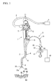
FIG. 1 is a diagram illustrating high-frequency forceps and an endoscope according to an embodiment of the present invention. -
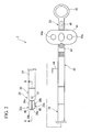
FIG 2 is a diagram illustrating the structure of the high-frequency forceps. -
FIG 3 is a cross-sectional view along the line III - III ofFIG. 2 . -
FIG. 4 is a diagram illustrating a set of energy forceps part of the high-frequency forceps in the open state. -
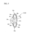
FIG. 5 is a diagram on Arrow A ofFIG. 4 . -
FIG 6 is a diagram illustrating the structure of high-frequency forceps according to an embodiment of the present invention. -
FIG 7 is a diagram on Arrow B ofFIG. 6 . -
FIG. 8 is a cross-sectional view of the distal end portion of biopsy forceps according to an embodiment of the present invention. -
FIG 9 is a diagram on Arrow C ofFIG. 8 . -
FIG. 10 is a cross-sectional view of the distal end portion of a ligature tool according to an embodiment of the present invention. -
FIG. 11 is a cross-sectional view along the line XI-XI ofFIG. 10 . -
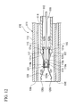
FIG. 12 is a cross-sectional view in which an internal sheath is received within an external sheath. -
FIG. 13 is a diagram in which an engagement of a pressing member and the internal sheath is released. -
FIG 14 is a diagram showing a clip retained within the body. -
- 1 endoscope
- 2 channel
- 3, 80 high-frequency forceps (treatment tool for endoscope)
- 21, 92, 111 treatment tool insertion portion
- 23a, 23b, 100, 118 operation wire (transmission member)
- 25, 84, 115 liquid conduit
- 30, 85 distal end cover (open/close member support portion)
- 32a, 32b forceps cup
- 33 liquid transport lumen
- 3 3 a, 116 distal end aperture
- 35, 101 insertion through-hole
- 91 biopsy forceps (treatment tool for endoscope)
- 95 open/close member support portion
- 99 biopsy cup
- 110 ligature tool (treatment tool for endoscope)
- 119 connecting member (open/close member support portion)
- 120 clip
- An explanation of an embodiment of the invention is provided hereafter, with reference to the drawings.
- First, an explanation is provided regarding to a first embodiment, with reference to
FIGS. 1 to 5 . In the present embodiment, an example is described in which the treatment tool for the endoscope is high-frequency forceps. - A schematic structure of an endoscope system which includes the treatment tool for the endoscope of the present embodiment is shown in
FIG 1 . As shown inFIG. 1 , the endoscope system comprises an endoscope 1, high-frequency forceps (treatment tool for endoscope) 3 inserted into theforceps channel 2 of the endoscope 1, and anendoscope body 5 connected via auniversal code 4 to the endoscope 1. - The endoscope 1 comprises a
flexible insertion portion 6 inserted into the living body, and anoperation portion 7 connected to the proximal end (outside of the body) of theinsertion portion 6, and theuniversal code 4. - To the distal end of the
insertion portion 6 is connected aflexible bend portion 8, to the distal end of which is connected a distal end cover 9. In the distal end cover 9 is housed a photographic image unit, not shown in the drawing, for observing the inside of the body, and an illumination unit which provides illumination light. On the distal end surface of the distal end cover 9 is formed an aperture of theforceps channel 2. Theforceps channel 2 comprises aforceps aperture 2a on the side of theoperation portion 7, which communicates to the inside and outside of the body. Toforceps aperture 2a is attached aforceps stopper 10. - The
operation portion 7 comprises, other than theforceps aperture 2a,plural switches 11 and plural operation knobs 12. On theswitches 11 is provided a switch to record an image photographed by the photographic unit, or a switch to change the illumination or the like. Signals of each switch is sent to the endoscopemain body 5 via the universal cable. The operation knobs 12 include a knob for directing theflexible bend portion 8 to a certain direction. - The endoscope
main body 5 is provided with a unit for processing or display of an image photographed by the endoscope 1, an illumination light source for photography, or the like. - As shown in
FIGS. 2 to 5 , the high-frequency forceps 3 are energy forceps that are capable of accomplishing hemostasis by burning the blood vessels W2, exposed by a cross section, the mucous membrane tissue W3 on the its periphery, or the submucosal layer tissue W4 and the like, made by an incision of the inner wall W1 of the digestive organs. The high-frequency forceps 3 comprise atreatment portion 22 provided in the distal end of the flexible treatmenttool insertion portion 21 and twooperation wires FIG. 3 ) which accomplish an open/close operation of thetreatment portion 22, and a treatmenttool operation portion 24 provided at the proximal end of a treatmenttool insertion portion 21. - As shown in
FIG 3 , the treatmenttool insertion portion 21 comprises an inner sheath in the form of acoil 25. Inside of theinner sheath 25 is formed aliquid conduit 26 in which liquid flows along theinner sheath 25. Within theliquid conduit 26 are insertedoperation wires inner sheath 25 is covered with a tubelikeouter sheath 27 formed from an insulation member. By this means, theinner sheath 25 is insulated by theouter sheath 27 from its outside. - As shown in
FIG. 2 andFIG 3 ,treatment portion 22 comprises a distal end cover (open/close member support portion) 30 secured to the distal end of the treatmenttool insertion portion 21, and a set of forceps cups (open/close members) 32a and 32b, supported so as to freely rotate by thepin 31 of thecover 30. - The distal end cover has an approximate cylindrical shape, and comprises a liquid transport lumen 33 which extends from the proximal end where it is attached to the treatment
tool insertion portion 21 to the distal end which faces the hemorrhage site. The liquid transport lumen 33 is a liquid conduit which passes through along the lengthwise direction of thedistal end cover 3. On the distal end surface of the distal end cover is formed adistal end aperture 33a of the liquid transport lumen 33. A singledistal end aperture 33a is arranged on the outside in the diameter direction orthogonal to the lengthwise direction of the forceps cups 32a and 32b, and thecover 30, which is open toward the tip (distal end). - In the distal end the
cover 30, aslit 34 is provided in parallel to the liquid transport lumen 33. Theslit 34 is a groove formed facing the proximal end side of the distal end thecover 30 from the distal end side of the distal end thecover 30. In theslit 34, two insertion through-holes 35 are provided in thewall 30a of the proximal end side of the distal end thecover 30, approximately parallel to the axis line of the distal end thecover 30. The insertion through-hole 35 communicates to the treatmenttool insertion portion 21 and theslit 34. In the insertion through-hole 35, one of theoperation wires - Each of the
forceps cup slit 34 provided in the distal end thecover 30. The forceps cups 32a and 32b comprisecups arms cups tool insertion portion 21 side). - As shown in
FIG. 5 , thecups indentations forceps surface 39a which forms an outer periphery of theindentation 38a connects to anothercup 36b, andplural grooves 40 are provided with a predetermined spacing. In the same manner, theforceps surface 39b which forms the outer periphery of theindentation 38b connects to anothercup 36a, andplural grooves 40 are provided with a predetermined spacing. - As shown in
FIG. 3 and FIG. 4 , thearm 37a offorceps cup 32a extends rearward from the proximal end of thecup 36a. Ahole 48a is formed in the rear portion of thearm 37a, and engages with the distal end of theoperation wire 23a. The distal end ofoperation wire 23b is rotatably supported by apin 31 between the end of thearm 37a and thecup 36a. In the same manner, ahole 48b is formed in the rear portion of thearm 37b, and engages with the distal end of theoperation wire 23b. The predetermined position ofarm 37b is supported by the pin 31 (seeFIG. 3 ) so as to freely rotate. The forceps cups 32a and 32b rotate about thepin 31. Each of thepins 31, thearms operation wires - The distal ends of
operation wire 23a andoperation wire 23b respectively engage withforceps cup 32a andforceps cup 32b, passing through the insertion through-hole 35 of the distal end thecover 30. Eachoperation wire operation wires operation wires tool insertion portion 21, and are drawn out to the treatmenttool operation portion 24, and connected to thehandle 41 of the treatmenttool operation portion 24. - The treatment
tool operation portion 24 comprises an operation componentmain body 42 and aslidable handle 41 relative to the operation componentmain body 42. - To the distal end of the operation component
main body 42 is connected the proximal end of the treatmenttool insertion portion 21. On the proximal end of the operation componentmain body 42 is provided afinger ring 43. In the distal end side of the operation componentmain body 42 is provided alure cock 44. The inner passage of thelure cock 44 passes within the operation componentmain body 42 and communicates to a liquid conduit 26 (seeFIG. 3 ). On thefinger ring 43 side of the operation componentmain body 42 is formed aslide groove 45 along the lengthwise direction of the operation componentmain body 42. In slide groove 45 ahandle 41 is inserted and mounted so as to be freely slidable. On thehandle 41 are secured theoperation wires main body 42. - The
handle 41 is provided withfinger holes operation wires electric power source 49 is connected to the terminal 47 (seeFIG. 1 ), the electric power of which can be conducted to the set of the forceps cups 32a and 32b. - To the
lure cock 44 can be attached a liquid supply device (not shown) in which a liquid is stored. As the liquid supply device, a syringe or a liquid pump may be used. As the liquid, water, physiological saline solution, a hemostat, or a stain solution and the like may be used. - An explanation of the operation of the high-
frequency forceps 3 is provided next. - Initially, the high-
frequency forceps 3 are inserted into thechannel 2 of the endoscope 1, and the terminal 47 is connected to the high-frequencyelectric power source 49. The distal ends of the high-frequency forceps 3 are positioned in a close proximity to the periphery of the hemorrhage site (for example, the blood vessel W2 shown inFIG. 1 ). Theinsertion portion 6 of the endoscope 1 is bent so that the distal end side of the distal end thecover 30 of the high-frequency forceps 3 faces the hemorrhage site. The liquid in thelure cock 44 of the treatment tool operation portion is connected to a syringe in which a liquid is stored, and the liquid delivered from the syringe to theliquid conduit 26 is sprayed facing the hemorrhage site through thedistal end aperture 33a from the liquid transport lumen 33 of thetreatment unit 22, being led to thetreatment unit 22 through aliquid conduit 26, flushing the blood on the periphery of the hemorrhage site. While confirming the hemorrhage site by means of the photographic unit of the endoscope 1, thehandle 41 of the treatmenttool operation portion 24 is slid, opening the set of the forceps cups 32a and 32b. - Specifically, by pressing the
handle 41 in the distal end side, theoperation wires operation wires arms pin 31 to the distal end thecover 30 move so as to be space apart in the direction approximately orthogonal to the lengthwise direction of thetreatment units 22. Each of the forceps cups 32a and 32b rotate about thepin 31, increasing the distance between each of the forceps surfaces 39a and 39b. - After opening the distal ends of the set of the forceps cups 32a and 32b of the
treatment unit 22, theentire frequency forceps 3 are advanced. When the distal ends of the forceps cups 32a and 32b make contact with the inner wall W1 of the digestive organs, thehandle 41 of the treatmenttool operation portion 24 is drawn back. Theoperation wires arms pin 31, closing the set of the forceps cups 32a and 32b. - The set of the forceps cups 32a and 32b, along with the submucosal layer tissue W4 on the periphery of the exposed blood vessels W2, sandwich the blood vessels W2 with
forceps surfaces indentations - When high-frequency electric current is applied from the high-frequency
electric power source 49, the submucosal layer tissue W4 making contact with the forceps surfaces 39a and 39b is cauterized such that the blood vessels W2 are included therein. - According to this embodiment, since a liquid transport lumen 33 is provided in the
treatment unit 22, liquid can be sprayed in a direction approximately parallel to the direction in which the set offorceps frequency forceps 3 are supported in a state in which they are inserted into the endoscope 1, liquid can be flushed on the periphery of the hemorrhage, the position of which can be accurately confirmed. Since the lengthwise direction of the liquid transport lumen and the direction in which the set of the forceps cups 32a and 32b extend are approximately parallel, the position of spraying the liquid can be identified, and hemostasis can be quickly and simply accomplished. - Since the liquid conduit and the liquid transport lumen 33 are provided in the treatment
tool insertion portion 21 of the high-frequency forceps 3 and the distal end thecover 30 as a unit, while washing the affected area using the liquid transport, or immediately after washing, hemostasis can be accomplished with radio waves, which facilitate the procedures. Since the liquid transport lumen 33 and the set of the forceps cups 32a and 32b are arranged in different positions, the structure of the device can be simplified. - Since the
distal end aperture 33a is formed closer to the proximal end side than thecup portions - The clearance (flow path area) at the time the operation wires pass through the
wall 30a of the distal end thecover 30 is sufficiently small compared to the flow path area of the liquid transport lumen 33. Accordingly, even if the insertion through-hole 35 of theoperation wires - In a configuration in which the operation wire passes through the liquid conduit, if the hole in the forceps cup through which the operation wire is drawn is large, then there would be a leakage of liquid, with the problem that liquid cannot be sprayed from the liquid conduit in the required amount. However, the structure of this embodiment solves such problems, and liquid transport can be accomplished to the required position with simple construction.
- First, an explanation is provided regarding to a second embodiment, with reference to
FIG. 6 andFIG. 7 . In the present embodiment, an example is provided in which the treatment tool for the endoscope is high-frequency forceps. Elements which are the same as those of the first embodiment are given the same symbols, and repetitive explanations are omitted. - As shown in
FIG. 6 andFIG. 7 , high-frequency forceps 80 are provided on atreatment unit 81 attached to the distal end of the flexible treatmenttool insertion portion 21. To the proximal end of the treatmenttool insertion portion 21 is attached a treatmenttool operation portion 83. Along thetreatment unit 81 and the treatmenttool insertion portion 21 is arranged aliquid conduit 84 which transports sprayed liquid toward the site of the hemorrhage. - In the
treatment unit 81, a set of the forceps cups 32a and 32b are supported so as to be freely rotated and face a distal end cover (open/close member support portion) 85. The forceps cups 32a and 32b have the same construction as that of the first embodiment. Thetreatment unit 81 is constructed so as to freely rotate about an unshown pin, by means of a link mechanism formed from thearms operation wires - The
operation wires handle 41 of the treatmenttool operation portion 83, passing through the inside of thedistal end cover 85 and the treatmenttool insertion portion 21. - As shown in
FIG. 7 , a part of the outer periphery of thedistal end cover 85 is indented. The distal end of aliquid conduit 84 is secured to theindentation 85a. Theindentation 85a is attached along the length of thedistal end cover 85 in a position which is approximately orthogonal to the open/close direction of the distal end of the set of the forceps cups 32a and 32b. A singledistal end aperture 84 is arranged on the outside in the diameter direction orthogonal to the lengthwise direction of the forceps cups 32a and 32b, anddistal end cover 85, which is open toward the tip (distal end). - As shown in
FIG. 6 ,liquid conduit 84 is flexible, at least the part secured to the outer surface of theexternal sheath 27. The proximal end of theliquid conduit 84 is secured to the operationmain body 86 of the treatmenttool operation portion 83. To the proximal end of theliquid conduit 84 is attached thelure cock 44 to which a syringe can be connected. - The outer surface of the operation portion
main body 86 of the treatmenttool operation portion 83 is secured to theliquid conduit 84. The operation portionmain body 86 is directly connected to theliquid conduit 84 and thelure cock 44. Other construction is the same as that of the first embodiment. - The
treatment unit 81 is used while being inserted in thechannel 2 of the endoscope 1. When accomplishing hemostasis, the distal end of thedistal end cover 85 is directed to the hemorrhage site side, and liquid is sent from a syringe. The liquid sent from the syringe is sprayed from the distal end of theliquid conduit 84, flushing the blood on the periphery of the hemorrhage. After confirming the site of the hemorrhage by means of the liquid transport, theoperation wires electric power source 49, and the submucosal layer tissue W4 in contact with the forceps surfaces 39a and 39b are cauterized while the blood vessels W2 is included therein - According to this embodiment, transportation of a liquid to the hemorrhage site and its periphery, and hemostasis can be quickly accomplished. In particular, since the
liquid conduit 84 is arranged on the outside of thetreatment unit 81 and the treatmenttool insertion portion 21, liquid transport and hemostasis can be accomplished with simple construction. Other effects are the same as those of the first embodiment. - First, an explanation is provided of a third embodiment, with reference to
FIGS. 8 and 9 . In the third embodiment, the treatment tool for the endoscope is biopsy forceps. The same symbols are applied to the same construction elements as those of the first embodiment. Explanations which are repetitive to those of the first embodiment are omitted. - As shown in
FIG. 8 and FIG. 9 , thebiopsy forceps 91 comprise a treatmenttool insertion portion 92 which is flexible and elongated. Asheath 93 of the treatmenttool insertion portion 92 is hollow. The lumen of thesheath 93 forms theliquid conduit 94. To the distal end of thesheath 93 is attached an integral the open/closemember support portion 95. The open/closemember support portion 95 is attached crossing the diameter direction, and forms an indentation which has theslit 96. Aliquid conduit 94 extends approximately in parallel to the axis line of thesheath 93. The distal end of theliquid conduit 94 branches into two liquid transport branch pipe passages which sandwich the open/closemember support portion 95, and formdistal end apertures 97 on the surface of thesheath 93. The twodistal end apertures 97 are arranged on the outside diameter orthogonal to the lengthwise direction of the biopsy cups 99 and the open/close support member 95, and are open toward the tip (distal end). As shown inFIG. 9 , thedistal end apertures 97 have a shape of a circle a part of which is clipped by the open/closemember support portion 95. - In the open/close
member support portion 95, thepin 98 crosses theslit 96 in a direction orthogonal to the axis line of thesheath 93. By means of thispin 98, biopsy cups 99 being a set of open/close members are freely supported so as to be opened or closed in the open/closemember support portion 95. The biopsy cups 99 comprisearms 99a supported by apin 98. At the tip of thearms 99a, cups 99b protrude closer to the distal end than thesheath 93. Eachcup 99b has indentation (not shown) which faces each other. The size of the set ofcups 99b in the closed state is less than the outer diameter of thesheath 93. In addition, the width of thecups 99b in the direction orthogonal to the direction of opening and closing thereof is narrower than the spacing between thedistal end apertures 97. The biopsy cups 99 are arranged so as to be sandwiched by the twoapertures 97. To the proximal end of thearms 99a of the biopsy cups 99 are coupledoperation wires 100. Theoperation wires 100 are pulled within a hollow thesheath 93 passing through the insertion through-hole 101 of the open/closemember support portion 95, and are coupled to an un-shown treatment tool operation portion. The treatment tool operation portion is constructed so as to exclude the terminal 47 from the treatmenttool operation portion 24 shown inFIG. 1 . - An insertion through-
hole 101 communicates to theliquid conduit 94 and theslit 96. However, the flow path area of the gap at the time when the operation wires are passed through the insertion through-hole 101 is sufficiently smaller than the flow path area of the liquid transportbranch pipe path 94a and thedistal end aperture 97. - In performing procedures with the
biopsy forceps 91, thebiopsy forceps 91 are inserted into the endoscope 1 (seeFIG. 1 ), and the biopsy cups 99 are placed in close proximity to a target site. When the target site cannot be confirmed from a hemorrhage, a physiological saline solution is injected from thelure cock 44, and is sprayed from thedistal end aperture 97 through theliquid conduit 94. The physiological saline solution reaches the target site without being shielded by the biopsy cups 99, and the hemorrhage is flushed. Operating thehandle 41, after opening the set of thebiopsy forceps 91, the entire treatmenttool insertion portion 92 is advanced, and the biopsy cups 99 are pressed against the target site. Subsequently, after closing the biopsy cups 99 and sandwiching the target site, the entire treatmenttool insertion portion 92 is withdrawn to the rear, and pulled off the target site to collect it. - Since the
biopsy forceps 91 havedistal end apertures 97 defined in a position distant from the moving range when the biopsy cups 99 is opened or closed, the biopsy cups 99 may be opened or closed while spraying a physiological saline solution. - When hemorrhaging occurs from the site from which the target site is collected, a hemostat is injected from the
lure cock 44, and is sprayed from thedistal end apertures 97, reaching the hemorrhage site without being shielded by the biopsy cups 99. - According to this embodiment, liquid transport can be accomplished while the set of biopsy cups 99 are closed, and the hemorrhage can be flushed prior to treatment. Accordingly, confirmation of the target site is facilitated. Since it is possible to accomplish liquid transport while the set of biopsy cups 99 are closed, the hemostat can be dispersed after collecting the body tissue of the target site, after which hemostasis can be quickly accomplished.
- By accomplishing liquid transport while the biopsy cups 99 are closed, since a large field of vision can be assured, liquid transport can be reliably realized. Since liquid transport can be accomplished when the biopsy cups 99 are opened or closed, a procedure can be quickly performed. Since the two
distal end apertures 97 are defined so as to sandwich the biopsy cups 99, liquid transport can be accomplished to a broad region which includes the target site. - The amount of liquid flowing from the
insertion opening 101 is made to be extremely small, with an assured amount of liquid flowing from thedistal end openings 97, assuring hemostasis and the ability to flush the hemorrhage. Since thecups 99b are positioned closer to the distal end side than the distal end openings 97a, a biopsy can be quickly performed. Other advantages are the same as those of the first embodiment. - Here, the treatment tool for the endoscope may be high-frequency forceps having the structure described in the third embodiment. Physiological saline solution can be transported from the
distal end aperture 97 and cauterization may be performed after confirming the hemorrhage site. - First, an explanation is provided regarding to a fourth embodiment, with reference to
FIG. 10 to FIG. 14 . In the fourth embodiment, the treatment tool for the endoscope is a ligature tool on which an open/close type clip is mounted. The same symbols are applied as for those of the same elements in the first embodiment, and explanations which would be repetitive those of the first embodiment are omitted. - As shown in
FIG. 10 , theligature tool 110 comprises a treatmenttool insertion portion 111 inserted in the treatment tool channel of the endoscope. The treatmenttool insertion portion 111 comprises anexternal sheath 112 which is flexible and elongated, and aninternal sheath 113 which can be freely inserted to or withdrawn from theexternal sheath 112. As shown inFIG. 11 , theexternal sheath 112 has ahole 114, in the center of which is inserted into theinternal sheath 113. In theexternal sheath 112, fourliquid conduits 115 extend to the outer periphery of the hole 1 14, approximately in parallel to the axis line. Accordingly, as shown inFIG. 10 , thedistal end 116 of theliquid conduit 115 formed on the distal end surface of theouter sheath 112 is arranged so as to enclosehole 114. - The
inner sheath 113 is formed from a tightly winded coil sheath. The periphery of the distal end aperture of theinner sheath 113 is astopper 117 having a reduced inner diameter. Anoperation wire 118 is inserted so as to freely advance into or be withdrawn from within theinner sheet 113. The distal end of theoperation wire 118 has an enlargediameter part 118a, to which a connectingmember 119 is attached as an integral open/close member support portion. Afragile portion 119a having a reduced thickness is formed in the distal end of connectingmember 119. On thefragile side 119a, aprotrusion 119b with which theclip 120 engages protrudes in a direction which is approximately orthogonal to the direction of the axis line. The connectingmember 119 is housed in a cylindrical pressingmember 121. - The pressing
member 121 has an approximate cylindrical shape, the proximal end of which has a broader diameter following the formation of the thinfragile portion 121 a. Theenlarged diameter portion 121 b is engageable with the proximal end side of thestopper 117 of theinner sheath 113. In addition, the distal end surface of thepressing member 121 is blocked by the two remainingslits 122. Theslits 122 are formed approximately parallel to the protruding direction of theprotrusion 119b of the connectingmember 119. To the outside of the center of the lengthwise direction of thepressing member 121 is attached anengagement piece 121 c which faces outwardly in the direction of the diameter. - To the
protrusion 119b of connectingmember 119 is engaged with theclip 120, which, for example, is folded around the center of a stainless steel band, and is engaged with theprotrusion 119b from the proximal end side. Theclip 120 comprises twoclip arms 120a which extend toward the distal end. Theclip arms 120a extend outwardly through each of twoslits 122. The distal end of theclip arms 120a pulled out from the pressingmember 121 form thenails 120b which are folded in the direction so as to come in close proximity. - To the proximal end of the
inner sheath 113 is connected the operation portion, which is constructed so as to remove the terminal 47 from the treatmenttool operation portion 24 shown inFIG. 1 . - An explanation of an operation of an embodiment is provided next.
- When accomplishing hemostasis with the
clip 120, theligature tool 110 is inserted into an endoscope. At this time, as shown inFIG. 12 , theinner sheath 113 has theclip 120 which is pulled into and is received within theouter sheath 112. If the distal end of theouter sheath 112 is connected in close proximity to the target site, theinner sheath 113 is advanced relative to theouter sheath 112, and theclip 120 is made protrude from the distal end of theouter sheath 112. When the target site cannot be confirmed from a hemorrhage, physiological saline solution is injected from thelure cock 44, and is sprayed from thedistal end aperture 116 through theliquid conduit 115. The physiological saline solution is sprayed from the respective fourdistal end apertures 116 and flushes the hemorrhage, primarily with a physiological saline solution fromdistal end apertures 116 which do not overlap theclip 120. - If the site of the hemorrhage is confirmed, the entire the
ligature tool 110 can be pressed in, by pressing theclip 120 onto the tissue of a living body, and by pulling thehandle 41 which sandwiches the hemorrhage site. When the connectingmember 119 is pulled by theoperation wire 118, the connectingmember 119 is withdrawn backward and theclip 120 is returned within the pressingmember 121. Theclip arms 120a are closed, they sandwich a hemorrhage site, and ligature is accomplished. By pushing thehandle 41 forward again to open theclip arms 120a, and ligature can be accomplished again to the hemorrhage site. - If the hemorrhage site is ligated by the
clip 120, thehandle 41 is strongly pulled further toward the hand, destroying thefragile portion 119a of the connectingmember 119. Theoperation wire 118 is pulled back, and the enlargediameter part 118a makes contact from the distal end side to theenlarged diameter portion 121b of thepressing member 121, pressing theenlarged diameter portion 121b to the proximal end side. As shown inFIG. 13 , the thinfragile portion 121a is broken, and the engagement between thepressing member 121 and theinner sheath 113 is released. As shown inFIG. 14 , theclip 120 which ligates the hemorrhage site and thepressing member 121 are retained within the body. - The present embodiment arranges four
distal end apertures 116 of theliquid conduit 115 on the outside as the diameter direction orthogonal to the lengthwise direction of theclip 120 and theinternal sheath 113, and directs the apertures toward the tip (distal end). Accordingly, liquid transport can be accomplished irrespective of the open/close state of theclip 120, making it possible to flush a hemorrhage beforehand. Accordingly, confirmation of the target site is easily accomplished. If liquid transport is accomplished until theclip 120 is closed, the field of vision can be assured to be large, guaranteeing the liquid transport. Since thedistal end apertures 116 are arranged in the peripheral direction, liquid transport can be assured irrespective of the rotating position of theclip 120 or of whether theclip 120 is opened or closed. The clip may also be constructed so that the clip arms can be closed only once. However, in this embodiment, it is desirable that theclip 120 capable of being opened and closed multiple times because applying ligature to a target site is assured. - The present invention can be broadly applied without being restricted to any of the embodiments.
- For example, the treatment tool for the endoscope may be provided with a nichrome line, to which direct electric current is conducted, whereby accomplishing hemostasis through the generation of heat. In addition, the treatment tool for the endoscope may be constructed so as to incise or remove a target site. Here, by spraying liquid from a liquid conduit, incision or removal may be accomplished while flushing a hemorrhage. At this time, the liquid used may include color elements.
- The treatment tool for an endoscope according to the present invention is capable of being used while being inserted into a channel of an endoscope.
Claims (5)
- An treatment tool for a endoscope, comprising:a treatment tool insertion portion to be inserted into a channel of the endoscope;an open/close member support portion formed in a distal end of the treatment tool insertion portion;an open/close member which is freely supported so as to be opened or closed and treats a target site;a liquid conduit which transports a liquid to a target site, liquid conduit being provided on an outside of the open/close member in a direction orthogonal to a lengthwise direction of the open/close member, and comprising at least one distal end aperture which opens toward the distal end direction of the open/close member support portion, the liquid conduit transports.
- The treatment tool for the endoscope according to Claim 1, wherein the distal end aperture of the liquid conduit is provided in a position which has shifted approximately 90 degrees around the axis line of the treatment tool insertion portion relative to an open/close direction of the open/close member.
- The treatment tool for the endoscope according to Claim 1, wherein the liquid conduit is provided on an outside of the treatment tool insertion portion.
- The treatment tool for the endoscope according to Claim 1, wherein the treatment tool for the endoscope is biopsy forceps, or high-frequency forceps, or a clip.
- An treatment tool for an endoscope, comprising:a treatment tool insertion portion to be inserted into a channel of the endoscope;an open/close member support portion formed in a distal end of the treatment tool insertion portion;an open/close member which is freely supported so as to be opened or closed and treats a target site;a transmission member which is coupled to the open/close member passing through a hole formed in the open/close member support portion from the treatment tool insertion portion in order to transmit a driving force on the open/close member side; anda liquid transport flow path which is provided within the treatment tool insertion portion and transports a liquid to a target site, the liquid transport flow path having a flow path area larger than a flow path area formed between the hole and transmission member.
Applications Claiming Priority (1)
| Application Number | Priority Date | Filing Date | Title |
|---|---|---|---|
| PCT/JP2005/014768 WO2007017949A1 (en) | 2005-08-11 | 2005-08-11 | Treatment device for endoscope |
Publications (2)
| Publication Number | Publication Date |
|---|---|
| EP1913876A1 true EP1913876A1 (en) | 2008-04-23 |
| EP1913876A4 EP1913876A4 (en) | 2009-11-11 |
Family
ID=37727145
Family Applications (1)
| Application Number | Title | Priority Date | Filing Date |
|---|---|---|---|
| EP05770426A Withdrawn EP1913876A4 (en) | 2005-08-11 | 2005-08-11 | Treatment device for endoscope |
Country Status (5)
| Country | Link |
|---|---|
| US (1) | US8932323B2 (en) |
| EP (1) | EP1913876A4 (en) |
| JP (1) | JP4690410B2 (en) |
| KR (1) | KR101164286B1 (en) |
| WO (1) | WO2007017949A1 (en) |
Cited By (3)
| Publication number | Priority date | Publication date | Assignee | Title |
|---|---|---|---|---|
| US20120310222A1 (en) * | 2010-11-01 | 2012-12-06 | Olympus Medical Systems Corp. | Treatment apparatus |
| CN108601602A (en) * | 2016-02-02 | 2018-09-28 | 奥林巴斯株式会社 | Endoscopic surgical utensil |
| EP3412235A4 (en) * | 2016-02-02 | 2019-10-02 | Olympus Corporation | Endoscopic instrument |
Families Citing this family (10)
| Publication number | Priority date | Publication date | Assignee | Title |
|---|---|---|---|---|
| CN101365388B (en) * | 2006-01-12 | 2011-03-23 | 多种活检标本有限责任公司 | A sampling apparatus for taking a number of samples |
| JP5588711B2 (en) * | 2010-03-30 | 2014-09-10 | 富士フイルム株式会社 | Ligation device |
| US9179968B2 (en) | 2010-05-10 | 2015-11-10 | St. Jude Medical Luxembourg Holding S.À.R.L. | Irrigated finned ablation head |
| JP5275527B1 (en) * | 2013-02-05 | 2013-08-28 | 富士システムズ株式会社 | Drain tube for washing electric knife |
| JP5198683B1 (en) * | 2012-11-21 | 2013-05-15 | 富士システムズ株式会社 | Drain tube for washing electric knife |
| JP5807082B2 (en) * | 2014-03-13 | 2015-11-10 | 富士フイルム株式会社 | Ligation device |
| JP2022035058A (en) * | 2020-08-20 | 2022-03-04 | 株式会社Biomedical Solutions | Biopsy forceps |
| KR102593540B1 (en) * | 2021-05-18 | 2023-10-23 | 한림대학교 산학협력단 | Endoscope clip device with multi-directional adjustment |
| KR102652179B1 (en) * | 2021-08-30 | 2024-03-29 | 주식회사 파인메딕스 | Hemostatic forceps for endoscope |
| WO2023248072A1 (en) * | 2022-06-22 | 2023-12-28 | Covidien Lp | Systems and methods for providing and operating dissecting catheters |
Citations (2)
| Publication number | Priority date | Publication date | Assignee | Title |
|---|---|---|---|---|
| US4919152A (en) * | 1987-03-02 | 1990-04-24 | Ralph Ger | Method of closing the opening of a hernial sac |
| US5456684A (en) * | 1994-09-08 | 1995-10-10 | Hutchinson Technology Incorporated | Multifunctional minimally invasive surgical instrument |
Family Cites Families (16)
| Publication number | Priority date | Publication date | Assignee | Title |
|---|---|---|---|---|
| JPS5233113A (en) | 1975-09-10 | 1977-03-14 | Roketsutoboiraa Kogyo Kk | Manufaceuring method for resisting pessure vessel |
| US5386817A (en) * | 1991-06-10 | 1995-02-07 | Endomedical Technologies, Inc. | Endoscope sheath and valve system |
| JPH0551314A (en) | 1991-08-20 | 1993-03-02 | Kanebo Ltd | Skin cosmetics |
| JPH0551314U (en) * | 1991-12-12 | 1993-07-09 | オリンパス光学工業株式会社 | Forceps for cell collection |
| US5354291A (en) * | 1992-10-09 | 1994-10-11 | Symbiosis Corporation | Probe for endoscopic suction-irrigation instruments having a proximal port for receiving an additional probe therethrough |
| US5373854A (en) * | 1993-07-15 | 1994-12-20 | Kolozsi; William Z. | Biopsy apparatus for use in endoscopy |
| JPH1147135A (en) * | 1997-08-06 | 1999-02-23 | Olympus Optical Co Ltd | Endoscope treatment instrument |
| US6059719A (en) * | 1997-08-06 | 2000-05-09 | Olympus Optical Co., Ltd. | Endoscope system |
| US6066102A (en) * | 1998-03-09 | 2000-05-23 | Spectrascience, Inc. | Optical biopsy forceps system and method of diagnosing tissue |
| JP4021052B2 (en) | 1998-06-01 | 2007-12-12 | オリンパス株式会社 | Treatment tool |
| JP2001327510A (en) * | 2000-05-22 | 2001-11-27 | Olympus Optical Co Ltd | Scattering treatment tool for endoscope |
| JP2001327512A (en) * | 2000-05-24 | 2001-11-27 | Asahi Optical Co Ltd | Treating implement for endoscope |
| US6786898B2 (en) * | 2003-01-15 | 2004-09-07 | Medtronic, Inc. | Methods and tools for accessing an anatomic space |
| CA2427944A1 (en) | 2001-10-08 | 2003-04-17 | Timcal Ag | Electrochemical cell |
| JP4131014B2 (en) | 2003-03-18 | 2008-08-13 | Hoya株式会社 | Endoscopic sputum treatment device |
| JP4624692B2 (en) * | 2004-02-13 | 2011-02-02 | オリンパス株式会社 | Endoscopic treatment tool |
-
2005
- 2005-08-11 JP JP2007529446A patent/JP4690410B2/en not_active Expired - Fee Related
- 2005-08-11 KR KR1020087003037A patent/KR101164286B1/en active IP Right Grant
- 2005-08-11 EP EP05770426A patent/EP1913876A4/en not_active Withdrawn
- 2005-08-11 WO PCT/JP2005/014768 patent/WO2007017949A1/en active Application Filing
-
2008
- 2008-02-08 US US12/028,407 patent/US8932323B2/en active Active
Patent Citations (2)
| Publication number | Priority date | Publication date | Assignee | Title |
|---|---|---|---|---|
| US4919152A (en) * | 1987-03-02 | 1990-04-24 | Ralph Ger | Method of closing the opening of a hernial sac |
| US5456684A (en) * | 1994-09-08 | 1995-10-10 | Hutchinson Technology Incorporated | Multifunctional minimally invasive surgical instrument |
Non-Patent Citations (1)
| Title |
|---|
| See also references of WO2007017949A1 * |
Cited By (7)
| Publication number | Priority date | Publication date | Assignee | Title |
|---|---|---|---|---|
| US20120310222A1 (en) * | 2010-11-01 | 2012-12-06 | Olympus Medical Systems Corp. | Treatment apparatus |
| CN108601602A (en) * | 2016-02-02 | 2018-09-28 | 奥林巴斯株式会社 | Endoscopic surgical utensil |
| EP3412227A4 (en) * | 2016-02-02 | 2019-09-04 | Olympus Corporation | Endoscope treatment tool |
| EP3412235A4 (en) * | 2016-02-02 | 2019-10-02 | Olympus Corporation | Endoscopic instrument |
| CN108601602B (en) * | 2016-02-02 | 2021-04-13 | 奥林巴斯株式会社 | Endoscopic treatment instrument |
| US10973540B2 (en) | 2016-02-02 | 2021-04-13 | Olympus Corporation | Endoscopic surgical device |
| US11207088B2 (en) | 2016-02-02 | 2021-12-28 | Olympus Corporation | Endoscopic surgical device |
Also Published As
| Publication number | Publication date |
|---|---|
| JP4690410B2 (en) | 2011-06-01 |
| KR20080042813A (en) | 2008-05-15 |
| WO2007017949A1 (en) | 2007-02-15 |
| US20080125809A1 (en) | 2008-05-29 |
| EP1913876A4 (en) | 2009-11-11 |
| KR101164286B1 (en) | 2012-07-09 |
| US8932323B2 (en) | 2015-01-13 |
| JPWO2007017949A1 (en) | 2009-02-19 |
Similar Documents
| Publication | Publication Date | Title |
|---|---|---|
| US8932323B2 (en) | Treatment tool for endoscope | |
| US20220386858A1 (en) | Cleaning system for imaging devices | |
| JP3722729B2 (en) | Endoscope treatment device | |
| US9456733B2 (en) | Endoscopic instrument having a deflectable distal tool | |
| KR20200072469A (en) | Electrosurgical ablation tool | |
| US20110046624A1 (en) | Single handled endoscopic vessel harvesting system with rotation control | |
| EP1948027B1 (en) | Tissue cutting devices having hemostasis capability | |
| US10973540B2 (en) | Endoscopic surgical device | |
| CN101227864A (en) | Treating implement for endoscope | |
| US20220071649A1 (en) | Endoscopic surgical device | |
| JP7195623B2 (en) | Electrosurgical device for delivering RF and/or microwave energy into living tissue | |
| CN102204843A (en) | Endoscopic high-frequency treatment instrument | |
| JP4624692B2 (en) | Endoscopic treatment tool | |
| JP2528223B2 (en) | High Frequency Incision Tool for Endoscope | |
| KR20070110787A (en) | High-frequency treatment tool | |
| CN116056652A (en) | Electrosurgical resector tool | |
| JP2023507907A (en) | electrosurgical cutting instrument | |
| JP4643250B2 (en) | Surgical instrument | |
| CN111065348B (en) | High-frequency treatment tool and endoscope system | |
| JP3716477B2 (en) | Dipole electrosurgical instrument | |
| WO2021181552A1 (en) | Electrode unit and electrode unit operation method | |
| US20230270494A1 (en) | Treatment apparatus for endoscopes and expandable frames | |
| WO2022250002A1 (en) | Endoscopic treatment implement | |
| CN114376651A (en) | Cavity tube adjusting instrument | |
| CN114795458A (en) | Treatment tool for endoscope |
Legal Events
| Date | Code | Title | Description |
|---|---|---|---|
| PUAI | Public reference made under article 153(3) epc to a published international application that has entered the european phase |
Free format text: ORIGINAL CODE: 0009012 |
|
| 17P | Request for examination filed |
Effective date: 20080214 |
|
| AK | Designated contracting states |
Kind code of ref document: A1 Designated state(s): DE FR GB IE |
|
| DAX | Request for extension of the european patent (deleted) | ||
| RBV | Designated contracting states (corrected) |
Designated state(s): DE FR GB IE |
|
| A4 | Supplementary search report drawn up and despatched |
Effective date: 20090914 |
|
| 17Q | First examination report despatched |
Effective date: 20091127 |
|
| STAA | Information on the status of an ep patent application or granted ep patent |
Free format text: STATUS: THE APPLICATION IS DEEMED TO BE WITHDRAWN |
|
| 18D | Application deemed to be withdrawn |
Effective date: 20100309 |