EP1920670A1 - Article of footwear with a stretchable upper and an articulated sole structure - Google Patents
Article of footwear with a stretchable upper and an articulated sole structure Download PDFInfo
- Publication number
- EP1920670A1 EP1920670A1 EP07025158A EP07025158A EP1920670A1 EP 1920670 A1 EP1920670 A1 EP 1920670A1 EP 07025158 A EP07025158 A EP 07025158A EP 07025158 A EP07025158 A EP 07025158A EP 1920670 A1 EP1920670 A1 EP 1920670A1
- Authority
- EP
- European Patent Office
- Prior art keywords
- footwear
- article
- sipes
- recited
- sipe
- Prior art date
- Legal status (The legal status is an assumption and is not a legal conclusion. Google has not performed a legal analysis and makes no representation as to the accuracy of the status listed.)
- Granted
Links
- 210000004744 fore-foot Anatomy 0.000 claims description 57
- 238000000034 method Methods 0.000 claims description 23
- 210000000452 mid-foot Anatomy 0.000 claims description 20
- 238000000465 moulding Methods 0.000 claims description 17
- 230000008569 process Effects 0.000 claims description 15
- 238000000748 compression moulding Methods 0.000 claims description 6
- 238000001746 injection moulding Methods 0.000 claims description 6
- 239000010410 layer Substances 0.000 description 137
- 210000002683 foot Anatomy 0.000 description 69
- 239000000463 material Substances 0.000 description 52
- 229920000642 polymer Polymers 0.000 description 21
- 230000033001 locomotion Effects 0.000 description 17
- 239000002356 single layer Substances 0.000 description 12
- 239000006261 foam material Substances 0.000 description 10
- 238000006243 chemical reaction Methods 0.000 description 9
- 239000011800 void material Substances 0.000 description 9
- 230000000694 effects Effects 0.000 description 8
- 230000000386 athletic effect Effects 0.000 description 7
- 230000002045 lasting effect Effects 0.000 description 7
- 239000004753 textile Substances 0.000 description 7
- 210000003371 toe Anatomy 0.000 description 7
- 210000003423 ankle Anatomy 0.000 description 6
- 239000006260 foam Substances 0.000 description 6
- 239000010985 leather Substances 0.000 description 6
- 239000002649 leather substitute Substances 0.000 description 6
- 230000000295 complement effect Effects 0.000 description 5
- 229920001971 elastomer Polymers 0.000 description 5
- 239000000853 adhesive Substances 0.000 description 4
- 230000001070 adhesive effect Effects 0.000 description 4
- 210000001255 hallux Anatomy 0.000 description 4
- 230000004048 modification Effects 0.000 description 4
- 238000012986 modification Methods 0.000 description 4
- 239000005060 rubber Substances 0.000 description 4
- 230000035807 sensation Effects 0.000 description 4
- CURLTUGMZLYLDI-UHFFFAOYSA-N Carbon dioxide Chemical compound O=C=O CURLTUGMZLYLDI-UHFFFAOYSA-N 0.000 description 3
- 230000008901 benefit Effects 0.000 description 3
- 238000010276 construction Methods 0.000 description 3
- 230000003247 decreasing effect Effects 0.000 description 3
- 239000012530 fluid Substances 0.000 description 3
- 238000004519 manufacturing process Methods 0.000 description 3
- IJGRMHOSHXDMSA-UHFFFAOYSA-N Atomic nitrogen Chemical compound N#N IJGRMHOSHXDMSA-UHFFFAOYSA-N 0.000 description 2
- 206010061225 Limb injury Diseases 0.000 description 2
- 229920005830 Polyurethane Foam Polymers 0.000 description 2
- 229910002092 carbon dioxide Inorganic materials 0.000 description 2
- 238000005520 cutting process Methods 0.000 description 2
- BFMKFCLXZSUVPI-UHFFFAOYSA-N ethyl but-3-enoate Chemical compound CCOC(=O)CC=C BFMKFCLXZSUVPI-UHFFFAOYSA-N 0.000 description 2
- 230000007935 neutral effect Effects 0.000 description 2
- 239000002952 polymeric resin Substances 0.000 description 2
- 239000011496 polyurethane foam Substances 0.000 description 2
- 229920002994 synthetic fiber Polymers 0.000 description 2
- 229920003002 synthetic resin Polymers 0.000 description 2
- 239000004758 synthetic textile Substances 0.000 description 2
- 208000017899 Foot injury Diseases 0.000 description 1
- 208000018982 Leg injury Diseases 0.000 description 1
- 238000010521 absorption reaction Methods 0.000 description 1
- 239000006229 carbon black Substances 0.000 description 1
- 239000001569 carbon dioxide Substances 0.000 description 1
- 239000003795 chemical substances by application Substances 0.000 description 1
- 150000001875 compounds Chemical class 0.000 description 1
- 238000001816 cooling Methods 0.000 description 1
- 230000001419 dependent effect Effects 0.000 description 1
- 239000000835 fiber Substances 0.000 description 1
- 230000005484 gravity Effects 0.000 description 1
- 238000007373 indentation Methods 0.000 description 1
- 238000005304 joining Methods 0.000 description 1
- 238000010329 laser etching Methods 0.000 description 1
- 230000007246 mechanism Effects 0.000 description 1
- 229910052757 nitrogen Inorganic materials 0.000 description 1
- 230000002093 peripheral effect Effects 0.000 description 1
- 230000035699 permeability Effects 0.000 description 1
- 239000002861 polymer material Substances 0.000 description 1
- 229920002635 polyurethane Polymers 0.000 description 1
- 239000004814 polyurethane Substances 0.000 description 1
- 239000005061 synthetic rubber Substances 0.000 description 1
- 238000009423 ventilation Methods 0.000 description 1
Images


Classifications
-
- A—HUMAN NECESSITIES
- A43—FOOTWEAR
- A43B—CHARACTERISTIC FEATURES OF FOOTWEAR; PARTS OF FOOTWEAR
- A43B13/00—Soles; Sole-and-heel integral units
- A43B13/14—Soles; Sole-and-heel integral units characterised by the constructive form
- A43B13/16—Pieced soles
-
- A—HUMAN NECESSITIES
- A43—FOOTWEAR
- A43B—CHARACTERISTIC FEATURES OF FOOTWEAR; PARTS OF FOOTWEAR
- A43B13/00—Soles; Sole-and-heel integral units
- A43B13/14—Soles; Sole-and-heel integral units characterised by the constructive form
- A43B13/141—Soles; Sole-and-heel integral units characterised by the constructive form with a part of the sole being flexible, e.g. permitting articulation or torsion
-
- A—HUMAN NECESSITIES
- A43—FOOTWEAR
- A43B—CHARACTERISTIC FEATURES OF FOOTWEAR; PARTS OF FOOTWEAR
- A43B23/00—Uppers; Boot legs; Stiffeners; Other single parts of footwear
- A43B23/02—Uppers; Boot legs
- A43B23/0205—Uppers; Boot legs characterised by the material
-
- A—HUMAN NECESSITIES
- A43—FOOTWEAR
- A43B—CHARACTERISTIC FEATURES OF FOOTWEAR; PARTS OF FOOTWEAR
- A43B23/00—Uppers; Boot legs; Stiffeners; Other single parts of footwear
- A43B23/02—Uppers; Boot legs
- A43B23/0205—Uppers; Boot legs characterised by the material
- A43B23/0215—Plastics or artificial leather
- A43B23/022—Plastics or artificial leather with waterproof breathable membranes
-
- A—HUMAN NECESSITIES
- A43—FOOTWEAR
- A43B—CHARACTERISTIC FEATURES OF FOOTWEAR; PARTS OF FOOTWEAR
- A43B23/00—Uppers; Boot legs; Stiffeners; Other single parts of footwear
- A43B23/02—Uppers; Boot legs
- A43B23/0205—Uppers; Boot legs characterised by the material
- A43B23/0235—Different layers of different material
-
- A—HUMAN NECESSITIES
- A43—FOOTWEAR
- A43B—CHARACTERISTIC FEATURES OF FOOTWEAR; PARTS OF FOOTWEAR
- A43B23/00—Uppers; Boot legs; Stiffeners; Other single parts of footwear
- A43B23/02—Uppers; Boot legs
- A43B23/0245—Uppers; Boot legs characterised by the constructive form
- A43B23/025—Uppers; Boot legs characterised by the constructive form assembled by stitching
-
- A—HUMAN NECESSITIES
- A43—FOOTWEAR
- A43B—CHARACTERISTIC FEATURES OF FOOTWEAR; PARTS OF FOOTWEAR
- A43B23/00—Uppers; Boot legs; Stiffeners; Other single parts of footwear
- A43B23/02—Uppers; Boot legs
- A43B23/0245—Uppers; Boot legs characterised by the constructive form
- A43B23/0255—Uppers; Boot legs characterised by the constructive form assembled by gluing or thermo bonding
-
- A—HUMAN NECESSITIES
- A43—FOOTWEAR
- A43B—CHARACTERISTIC FEATURES OF FOOTWEAR; PARTS OF FOOTWEAR
- A43B23/00—Uppers; Boot legs; Stiffeners; Other single parts of footwear
- A43B23/02—Uppers; Boot legs
- A43B23/0245—Uppers; Boot legs characterised by the constructive form
- A43B23/0265—Uppers; Boot legs characterised by the constructive form having different properties in different directions
- A43B23/027—Uppers; Boot legs characterised by the constructive form having different properties in different directions with a part of the upper particularly flexible, e.g. permitting articulation or torsion
-
- A—HUMAN NECESSITIES
- A43—FOOTWEAR
- A43B—CHARACTERISTIC FEATURES OF FOOTWEAR; PARTS OF FOOTWEAR
- A43B23/00—Uppers; Boot legs; Stiffeners; Other single parts of footwear
- A43B23/02—Uppers; Boot legs
- A43B23/04—Uppers made of one piece; Uppers with inserted gussets
-
- A—HUMAN NECESSITIES
- A43—FOOTWEAR
- A43B—CHARACTERISTIC FEATURES OF FOOTWEAR; PARTS OF FOOTWEAR
- A43B23/00—Uppers; Boot legs; Stiffeners; Other single parts of footwear
- A43B23/08—Heel stiffeners; Toe stiffeners
- A43B23/088—Heel stiffeners
-
- A—HUMAN NECESSITIES
- A43—FOOTWEAR
- A43B—CHARACTERISTIC FEATURES OF FOOTWEAR; PARTS OF FOOTWEAR
- A43B23/00—Uppers; Boot legs; Stiffeners; Other single parts of footwear
- A43B23/08—Heel stiffeners; Toe stiffeners
- A43B23/16—Heel stiffeners; Toe stiffeners made of impregnated fabrics, plastics or the like
- A43B23/17—Heel stiffeners; Toe stiffeners made of impregnated fabrics, plastics or the like made of plastics
-
- A—HUMAN NECESSITIES
- A43—FOOTWEAR
- A43B—CHARACTERISTIC FEATURES OF FOOTWEAR; PARTS OF FOOTWEAR
- A43B3/00—Footwear characterised by the shape or the use
- A43B3/0036—Footwear characterised by the shape or the use characterised by a special shape or design
- A43B3/0057—S-shaped
-
- A—HUMAN NECESSITIES
- A43—FOOTWEAR
- A43B—CHARACTERISTIC FEATURES OF FOOTWEAR; PARTS OF FOOTWEAR
- A43B7/00—Footwear with health or hygienic arrangements
- A43B7/06—Footwear with health or hygienic arrangements ventilated
-
- B—PERFORMING OPERATIONS; TRANSPORTING
- B29—WORKING OF PLASTICS; WORKING OF SUBSTANCES IN A PLASTIC STATE IN GENERAL
- B29D—PRODUCING PARTICULAR ARTICLES FROM PLASTICS OR FROM SUBSTANCES IN A PLASTIC STATE
- B29D35/00—Producing footwear
- B29D35/12—Producing parts thereof, e.g. soles, heels, uppers, by a moulding technique
- B29D35/122—Soles
-
- B—PERFORMING OPERATIONS; TRANSPORTING
- B29—WORKING OF PLASTICS; WORKING OF SUBSTANCES IN A PLASTIC STATE IN GENERAL
- B29D—PRODUCING PARTICULAR ARTICLES FROM PLASTICS OR FROM SUBSTANCES IN A PLASTIC STATE
- B29D35/00—Producing footwear
- B29D35/12—Producing parts thereof, e.g. soles, heels, uppers, by a moulding technique
- B29D35/128—Moulds or apparatus therefor
-
- B—PERFORMING OPERATIONS; TRANSPORTING
- B29—WORKING OF PLASTICS; WORKING OF SUBSTANCES IN A PLASTIC STATE IN GENERAL
- B29C—SHAPING OR JOINING OF PLASTICS; SHAPING OF MATERIAL IN A PLASTIC STATE, NOT OTHERWISE PROVIDED FOR; AFTER-TREATMENT OF THE SHAPED PRODUCTS, e.g. REPAIRING
- B29C33/00—Moulds or cores; Details thereof or accessories therefor
- B29C33/42—Moulds or cores; Details thereof or accessories therefor characterised by the shape of the moulding surface, e.g. ribs or grooves
- B29C33/424—Moulding surfaces provided with means for marking or patterning
-
- B—PERFORMING OPERATIONS; TRANSPORTING
- B29—WORKING OF PLASTICS; WORKING OF SUBSTANCES IN A PLASTIC STATE IN GENERAL
- B29L—INDEXING SCHEME ASSOCIATED WITH SUBCLASS B29C, RELATING TO PARTICULAR ARTICLES
- B29L2031/00—Other particular articles
- B29L2031/48—Wearing apparel
- B29L2031/50—Footwear, e.g. shoes or parts thereof
Definitions
- the present invention relates to the field of footwear.
- the invention concerns, more particularly, an article of footwear having a stretchable upper and a sole structure with a plurality of incisions that impart an articulated configuration with flexibility in selected directions.
- Conventional articles of athletic footwear include two primary elements, an upper and a sole structure.
- the upper provides a covering for the foot that securely receives and positions the foot with respect to the sole structure.
- the upper may have a configuration that protects the foot and provides ventilation; thereby cooling the foot and removing perspiration.
- the sole structure is secured to a lower surface of the upper and is generally positioned between the foot and the ground.
- the sole structure may provide traction and control potentially harmful foot motion, such as over pronation.
- the upper and the sole structure operate cooperatively to provide a comfortable structure that is suited for a wide variety of ambulatory activities, such as walking and running.
- the general features and configuration of the upper and the sole structure are discussed in greater detail below.
- the upper forms a void on the interior of the footwear for receiving the foot.
- the void has the general shape of the foot, and access to the void is provided by an ankle opening. Accordingly, the upper extends over the instep and toe areas of the foot, along the medial and lateral sides of the foot, and around the heel area of the foot.
- a lacing system is often incorporated into the upper to selectively increase the size of the ankle opening and permit the wearer to modify certain dimensions of the upper, particularly girth, to accommodate feet with varying proportions.
- the upper may include a tongue that extends under the lacing system to enhance the comfort of the footwear, and the upper may include a heel counter to limit movement of the heel.
- the upper of an article of athletic footwear may be formed from multiple material layers that include an exterior layer, a middle layer, and an interior layer.
- the materials forming the exterior layer of the upper may be selected based upon the properties of wear-resistance, flexibility, and air-permeability, for example.
- the exterior layer the toe area and the heel area may be formed of leather, synthetic leather, or a rubber material to impart a relatively high degree of wear-resistance.
- Leather, synthetic leather, and rubber materials may not exhibit the desired degree of flexibility and air-permeability.
- various other areas of the exterior layer of the upper may be formed from a synthetic textile.
- the exterior layer of the upper may be formed, therefore, from numerous material elements that each impart different properties to specific areas of the upper.
- a middle layer of the upper may be formed from a lightweight polymer foam material that provides cushioning and protects the foot from objects that may contact the upper.
- an interior layer of the upper may be formed of a moisture-wicking textile that removes perspiration from the area immediately surrounding the foot.
- the various layers may be joined with an adhesive, and stitching may be utilized to join elements within a single layer or to reinforce specific areas of the upper.
- the sole structure generally incorporates multiple layers that are conventionally referred to as an insole, a midsole, and an outsole.
- the insole is a thin, cushioning member located within the upper and adjacent the plantar (lower) surface of the foot to enhance footwear comfort.
- the midsole which is traditionally attached to the upper along the entire length of the upper, forms the middle layer of the sole structure and serves a variety of purposes that include controlling foot motions and providing cushioning.
- the outsole forms the ground-contacting element of footwear and is usually fashioned from a durable, wear-resistant material that includes texturing to improve traction.
- the primary element of a conventional midsole is a resilient, polymer foam material, such as polyurethane or ethylvinylacetate, that extends throughout the length of the footwear.
- the properties of the polymer foam material in the midsole are primarily dependent upon factors that include the dimensional configuration of the midsole and the specific characteristics of the material selected for the polymer foam, including the density of the polymer foam material. By varying these factors throughout the midsole, the relative stiffness, degree of ground reaction force attenuation, and energy absorption properties may be altered to meet the specific demands of the activity for which the footwear is intended to be used.
- conventional midsoles may include, for example, stability devices that resist over-pronation and moderators that distribute ground reaction forces.
- stability devices that resist over-pronation and moderators that distribute ground reaction forces.
- the use of polymer foam materials in athletic footwear midsoles, while providing protection against ground reaction forces, may introduce instability that contributes to a tendency for over-pronation. Although pronation is normal, it may be a potential source of foot and leg injury, particularly if it is excessive.
- Stability devices are often incorporated into the polymer foam material of the midsoles to control the degree of pronation in the foot. Examples of stability devices are found in U.S. Patent Numbers 4,255,877 to Bowerman ; 4,287,675 to Norton et al. ; 4,288,929 to Norton et al.
- conventional midsoles may include fluid-filled bladders, as disclosed in U.S. Patent Numbers 4,183,156 and 4,219,945 to Rudy , for example.
- the present invention is an article of footwear having at least one of a stretchable upper and an articulated sole structure.
- the upper includes an exterior layer and an interior layer.
- the exterior layer forms at least a portion of an exterior of the upper, and the exterior layer includes a plurality of incisions that extend through the exterior layer.
- the interior layer is located adjacent at least a portion of an inner surface of the exterior layer, and the interior layer is exposed through at least a portion of the incisions.
- the incisions may include a first group and a second group.
- the first group may be oriented to provide stretch in a direction that extends between a medial side and a lateral side of the upper, and the second group of the incisions may be positioned adjacent the medial side and in a forefoot region of the upper.
- the sole structure includes a connecting portion and a plurality of discrete sole elements.
- the connecting portion is positioned adjacent the upper and may extend along a longitudinal length of the upper.
- the sole elements extend downward from the connecting portion, and the sole elements are separated by a plurality of sipes that extend upward into the midsole.
- the connecting portion may be configured to have a varying thickness. Accordingly, the connecting portion may exhibit a first thickness in the forefoot region of the footwear, a second thickness in a midfoot region of the footwear, and a third thickness in the heel region of the footwear, with the first and third thicknesses being less than the second thickness.
- the sipes may include a first sipe, a second sipe, and a plurality of third sipes. The first sipe may be oriented in the longitudinal direction and may extend through an entire length of the midsole. The second sipe may extend in the longitudinal direction and through only a portion of the length of the midsole. The third sipes may extend laterally from the medial side to the lateral side of the midsole.
- Figure 1 is a lateral elevational view of the footwear.
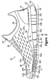
- Figure 2 is a medial elevational view of the footwear.
- Figure 3 is a top plan view of the footwear.
- Figure 4A is a first cross-sectional view of the footwear, as defined by section line 4A-4A in Figure 3 .
- Figure 4B is a second cross-sectional view of the footwear, as defined by section line 4B-4B in Figure 3 .
- Figure 5 is a rear elevational view of the footwear.
- Figure 6 is a lateral elevational view that illustrates the footwear when receiving a foot.
- Figure 7 is a partial lateral elevational view of the footwear in a flexed configuration.
- Figure 8 is a bottom plan view of the sole structure.
- Figure 9A is a first cross-sectional view of the sole structure, as defined by section line 9A-9A in Figure 8 .
- Figure 9B is a second cross-sectional view of the sole structure, as defined by section line 9B-9B in Figure 8 .
- Figure 9C is a third cross-sectional view of the sole structure, as defined by section line 9C-9C in Figure 8 .
- Figure 9D is a fourth cross-sectional view of the sole structure, as defined by section line 9D-9D in Figure 8 .
- Figure 9E is a fifth cross-sectional view of the sole structure, as defined by section line 9E-9E in Figure 8 .
- Figure 9F is a sixth cross-sectional view of the sole structure, as defined by section line 9F-9F in Figure 8 .
- Figure 9G is a seventh cross-sectional view of the sole structure, as defined by section line 9G-9G in Figure 8 .
- Figure 10A is a cross-sectional view of an alternate embodiment that corresponds with the location of section line 9A-9A in Figure 8 .
- Figure 11 is a bottom plan view of an insole portion of the footwear.
- Figure 12 is a bottom plan view of another insole portion of the footwear.
- Footwear 10 is depicted in the figures and discussed below as having a configuration that is suitable for athletic activities, particularly running.
- the concepts disclosed with respect to footwear 10 may, however, be applied to footwear styles that are specifically designed for a wide range of other athletic activities, including basketball, baseball, football, soccer, walking, and hiking, for example, and may also be applied to various non-athletic footwear styles. Accordingly, one skilled in the relevant art will recognize that the concepts disclosed herein may be applied to a wide range of footwear styles and are not limited to the specific embodiments discussed below and depicted in the figures.
- Footwear 10 is depicted in Figures 1-7 and includes an upper 20 and a sole structure 30.
- Upper 20 is formed from various material elements that are stitched or adhesively-bonded together to form an interior void that comfortably receives a foot and secures the position of the foot relative to sole structure 30.
- Sole structure 30 is secured to a lower portion of upper 20 and provides a durable, wear-resistant component for attenuating ground reaction forces and absorbing energy (i.e., providing cushioning) as footwear 10 impacts the ground.
- a conventional sole structure may have a relatively stiff or inflexible construction that inhibits the natural motion of the foot.
- Upper 20 and sole structure 30 have a structure that cooperatively articulate, flex, stretch, or otherwise move to provide an individual with a sensation of natural, barefoot running. That is, upper 20 and sole structure 30 are configured to complement the natural motion of the foot during running or other activities. In contrast with barefoot running, however, sole structure 30 attenuates ground reaction forces and absorbs energy to cushion the foot and decrease the overall stress upon the foot.
- footwear 10 may be divided into three general regions: a forefoot region 11, a midfoot region 12, and a heel region 13, as defined in Figures 1 and 2 .
- Regions 11-13 are not intended to demarcate precise areas of footwear 10. Rather, regions 11-13 are intended to represent general areas of footwear 10 that provide a frame of reference during the following discussion. Although regions 11-13 apply generally to footwear 10, references to regions 11-13 may also apply specifically to upper 20, sole structure 30, or an individual component or portion within either of upper 20 or sole structure 30.
- upper 20 combine to provide a structure having a lateral side 21, an opposite medial side 22, a tongue 23, and a lasting sock 24 that form the void within upper 20.
- Lateral side 21 extends through each of regions 11-13 and is generally configured to contact and cover a lateral surface of the foot.
- a portion of lateral side 21 extends over an instep of the foot and overlaps a lateral side of tongue 23.
- Medial side 22 has a similar configuration that generally corresponds with a medial surface of the foot.
- a portion of medial side 22 also extends over the instep of the foot and overlaps an opposite medial side of tongue 23.
- lateral side 21, medial side 22, and tongue 23 cooperatively form an ankle opening 25 in heel region 13 to provide the foot with access to the void within upper 20.
- Tongue 23 extends longitudinally along upper 20 and is positioned to contact the instep area of the foot. Side portions of tongue 23 are secured to an interior surface of each of lateral side 21 and medial side 22. A lace 26 extends over tongue 23 and through apertures formed in lateral side 21 and medial side 22. Tongue 23 extends under lace 26 to separate lace 26 from the instep area of the foot.
- the tension in lateral side 21 and medial side 22 may be increased so as to draw lateral side 21 and medial side 22 into contact with the foot.
- the tension in lateral side 21 and medial side 22 may be decreased so as to provide additional volume for the foot within upper 20.
- This general configuration provides, therefore, a mechanism for adjusting the fit of upper 20 and accommodating various foot dimensions.
- upper 20 may be formed from combinations of leather, synthetic leather, natural or synthetic textiles, polymer sheets, polymer foams, mesh textiles, felts, non-woven polymers, or rubber materials, for example.
- the exposed portions of upper 20 are formed from two coextensive layers of material that are stitched or adhesively bonded together. As depicted in Figure 4A and 4B , the layers include an exterior layer 14 and an adjacent interior layer 15. Exterior layer 14 is positioned on an exterior of upper 20, and interior layer 15 is positioned on an interior of upper 20 so as to form a surface of the void within upper 20.
- Lasting sock 24 is secured to a lower edge of layers 14 and 15 and extends along the upper surface of sole structure 30.
- the materials forming layers 14 and 15 may vary in different areas of upper 20, and only one or more of layers 14 and 15 may be present in some areas of upper 20.
- suitable materials for exterior layer 14 are various textiles, whether woven or non-woven, leather, synthetic leather, or a single layer mesh, for example, and interior layer 15 may be formed from similar materials.
- the materials that form tongue 23 and the area around ankle opening 26 may be different than the materials discussed above.
- exterior layer 14 may be formed from a material that includes two spaced textile layers interconnected by a plurality of connecting fibers. One or both of the textile layers may be a mesh material to enhance the air-permeability of upper 20 in this area.
- a foam material may be interposed between exterior layer 14 and interior layer 15.
- a portion of upper 20 may only include a single layer.
- the area of upper 20 located within heel region 13 and extending around the rear portion of heel region 13 is formed solely from interior layer 15. That is, exterior layer 14 and is absent in this portion of heel region 13 such that interior layer 15 forms both the exterior and interior of upper 20.
- the portion of upper 20 in heel region 13 may incorporate a conventional heel counter formed of a semirigid polymer material, for example, to ensure that the heel remains properly positioned with respect to upper 20.
- the heel counter may be located on an exterior of upper 20 or within the various material elements forming upper 20. As will be discussed below, however, the configuration of upper 20 and sole structure 30 does not necessitate the presence of a heel counter.
- the various portions of upper 20 include different combinations of materials that form layers 14 and 15.
- the materials forming exterior layer 14 and interior layer 15 in the areas of tongue 23 and around ankle opening 26 may be different than the materials forming exterior layer 14 and interior layer 15 in the areas of lateral side 21 and medial side 22 that extend through forefoot region 11 and midfoot region 12.
- the material forming interior layer 15 is the same throughout both of these areas, and the same material extends around the rearmost portion of heel region 13. Accordingly, the same material may form a substantial portion of the interior surface of upper 20.
- different materials may be utilized for the various areas of interior layer 15, or upper 20 may include more than two layers of material.
- Exterior layer 14 includes a plurality of incisions 27a and 27b that expose underlying portions of interior layer 15. By exposing interior layer 15, the stretch properties of upper 20 are selectively modified. In areas where no incisions 27a and 27b are present, each of layers 14 and 15 contribute to the stretch-resistance of upper 20. In areas where incisions 27a and 27b are present, however, incisions 27a and 27b permit exterior layer 14 to stretch to a greater degree. Accordingly, incisions 27a and 27b are formed in upper 20 to selectively vary the degree of stretch in specific portions of upper 20. In addition, incisions 27a and 27b may be utilized to vary the air-permeability, flexibility, and overall aesthetics (e.g., color) of upper 20.
- incisions 27a and 27b may be utilized to vary the air-permeability, flexibility, and overall aesthetics (e.g., color) of upper 20.
- incisions 27a and 27b are depicted as being distributed over the areas of lateral side 21 and medial side 22 that extend through forefoot region 11 and midfoot region 12.
- incisions 27a have a linear configuration and are oriented to extend longitudinally with respect to footwear 10. That is, incisions 27a are oriented in a direction that extends between forefoot region 11 and heel region 13. In an area of forefoot region 11 that corresponds with the hallux (i.e., the big toe), however, incisions 27b are oriented to extend laterally.
- incisions 27a and 27b has an effect upon the directions of stretch imparted by incisions 27a and 27b.
- incisions 27a and 27b do not increase the stretch in a direction that corresponds with the linear orientation of incisions 27a and 27b. That is, a particular incision 27a and 27b does not increase the stretch in a direction that is parallel to that incision 27.
- Incisions 27a and 27b do, however, increase the stretch of upper 20 in a direction that is perpendicular to the linear orientation of incisions 27a and 27b.
- Incisions 27a are depicted as forming lines of slits that extend longitudinally, and the incisions 27a in adjacent lines are offset from each other.
- incisions 27b are depicted as forming lines of slits that extend laterally, and the incisions 27b in adjacent lines are offset from each other.
- the various incisions 27a and 27b may be added to upper 20 in other arrangements.
- incisions 27a and 27b may be offset so as to not form lines, or incisions 27a and 27b may be randomly placed with respect to upper 20.
- Incisions 27a are oriented longitudinally with respect to footwear 10.
- incisions 27a permit upper 20 to stretch in a manner that increases the girth of upper 20. That is, incisions 27a stretch in a direction that is perpendicular to the longitudinal orientation of incisions 27a.
- Incisions 27b stretch in a similar manner. As discussed above, however, incisions 27b are oriented laterally. Accordingly, incisions 27b stretch in the longitudinal direction.
- Incisions 27a and 27b are depicted as being linear cuts in exterior layer 14. When a stretching force is exerted upon exterior layer 14 and in a direction that is generally perpendicular to one or more of incisions 27a and 27b, edges of the incisions 27a and 27b separate and form a generally elliptical shape with pointed ends, as depicted in Figure 6 . Incisions 27a and 27b are depicted as having a relatively linear and short configuration. Within the scope of the present invention, however, incisions 27a and 27b may exhibit a straight or curved configuration, for example, and the length of the various incisions 27a and 27b may be modified.
- Differences in the shape and length of incisions 27a and 27b may be utilized, for example, to modify the desired degree of stretch in upper 20, the air permeability of upper 20, and the flexibility and overall aesthetics of upper 20.
- Factors that may also be considered when determining the shape and length of incisions 27a and 27b include the materials utilized within upper 20, the degree of inherent stretch in the materials, and the directions in which stretch is desired, for example.
- the materials forming a conventional upper are often stitched or otherwise sewn to each other, and an adhesive bond may be utilized to secure coextensive portions of the materials to each other.
- layers 14 and 15 are arranged in a coextensive manner and may be bonded to each other. In some embodiments, however, layers 14 and 15 may be separate with no bonding. That is, layers 14 and 15 may be positioned adjacent to each other but not secured together except at edges or stress points, for example, so that interior layer 15 is unsecured to the exterior layer 14 in areas that are proximal to incisions 27a and 27b.
- An advantage of this configuration is that exterior layer 14 may stretch and move independent of interior layer 15.
- incisions 27a and 27b may permit stretch in exterior layer 14 that is not significantly hindered through an adhesion between layers 14 and 15. In general, therefore, layers 14 and 15 may not be adhered or otherwise secured together in areas that include incisions 27a and 27b.
- Incisions 27a and 27b are depicted as being formed in exterior layer 14. Within the scope of the present invention, however, incisions 27a and 27b may also be formed in one or both of layers 14 and 15. For example, incisions 27a and 27b may be formed in only exterior layer 14, both exterior layer 14 and interior layer 15, or in only interior layer 15. In some embodiments where both of layers 14 and 15 include incisions 27a and 27b, the incisions 27a and 27b may aligned or offset. Based upon the preceding discussion, therefore, the configuration of incisions 27a and 27b may vary considerably within the scope of the present invention.
- Incisions 27a and 27b may be formed through a variety of methods.
- incisions 27a and 27b may be formed with a cutting instrument, such as a die, knife, or razor.
- a laser apparatus may be employed to form incisions 27a and 27b and cut exterior layer 14 from a larger material element.
- Incisions 27a and 27b may be formed, therefore, by directing a laser at exterior layer 14 to remove the portions of exterior layer 14 that correspond with incisions 27a and 27b.
- the width of incisions 27a and 27b may approximately correspond with the width of the laser. Alternately, multiple passes of the laser may be utilized to form incisions 27a and 27b with a greater width.
- the laser apparatus may have the capacity to produce a laser beam of variable intensity by adjusting the power of the laser beam.
- the focus of the laser beam and the velocity of the laser beam relative to exterior layer 14 may be varied.
- An example of a suitable laser apparatus is any of the conventional CO 2 or Nd:YAG laser apparatuses, as disclosed in U.S. Patent Numbers 5,990,444 and 6,140,602 to Costin, which are hereby incorporated by reference.
- the power of the laser beam that forms incisions 27a and 27b is generally in a range of 0.25 to 25 watts, for example. If the laser beam has a relatively narrow focus, the power of the laser beam may be decreased to account for the greater energy per unit area in the laser beam. Similarly, if the laser beam has a relatively wide focus, the power of the laser beam may be increased to account for the lesser energy per unit area in the laser beam. Modifications to the velocity of the laser beam may also be utilized to account for the focus and power of the laser beam.
- incisions 27a and 27b materials such as leather, synthetic leather, and polymer textiles may require a relatively small power to form incisions 27a and 27b
- other materials such as high-density polymers may require greater power to form incisions 27a and 27b to the same depth. Accordingly, many factors are considered in determining the proper power, focus, and/or velocity of the laser beam for forming incisions 27a and 27b.
- the laser apparatus may include an emitter for the laser beam that moves adjacent to exterior layer 14 and forms incisions 27a and 27b in exterior layer 14. That is, the shape of the various incisions 27a and 27b may be controlled by movements of the laser apparatus relative to exterior layer 14. Alternately, the laser beam may reflect off of one or more movable or pivotable mirrors, and the shape of incisions 27a and 27b in exterior layer 14 may be controlled by movements of the mirrors.
- the laser beam heats selected areas of exterior layer 14 and forms incisions 27a and 27b by burning or incinerating the selected areas of exterior layer 14.
- incisions 27a and 27b may be formed in the presence of a non-combustible fluid, such as carbon dioxide or nitrogen. That is, the laser apparatus may be configured to emit a non-combustible fluid when the laser beam is forming incisions 27a and 27b.
- incisions 27a and 27b are formed in exterior layer 14, the various elements of upper 20 are assembled around a last that imparts the general shape of a foot to the void within upper 20. That is, the various elements are assembled around the last to form lateral side 21 and medial side 22 of upper 20, which extend from forefoot region 11 to heel region 13.
- the instep area is formed to include tongue 23 and lace 26, for example, and ankle opening 25 is formed in heel region 13.
- Lasting sock 24 is also secured to lower edges of lateral side 21 and medial side 22, and lasting sock 24 extends under the last to form a lower surface of the void within upper 20.
- a portion of sole structure 30 is then permanently secured to a lower area of upper 20, which includes lasting sock 24.
- adhesives, stitching, or a combination of adhesives and stitching may be utilized. In this manner, upper 20 is secured to sole structure 30 through a substantially conventional process.
- Sole structure 30 includes an insole 31 (depicted in greater detail below), a midsole 32, and an outsole 33.
- Insole 30 is positioned within upper 20 and adjacent to the upper surface of lasting sock 24 in order to contact the plantar (lower) surface of the foot and enhance the comfort of footwear 10.
- Midsole 32 is secured to a lower portion of upper 20, including lasting sock 24, and is positioned to extend under the foot during use.
- midsole 32 attenuates ground reaction forces and absorbs energy (i.e., imparts cushioning) when walking or running, for example
- Suitable materials for midsole 32 are any of the conventional polymer foams that are utilized in footwear midsoles, including ethylvinylacetate and polyurethane foam.
- Midsole 32 may also be formed from a relatively lightweight polyurethane foam having a specific gravity of approximately 0.22, as manufactured by Bayer AG under the BAYFLEX trademark.
- Outsole 33 is secured to a lower surface of midsole 32 to provide wear-resistance, and outsole 33 may be recessed within midsole 32. Although outsole 33 may extend throughout the lower surface of midsole 32, outsole 33 is located within heel portion 13 in the particular embodiment depicted in the figures.
- Suitable materials for outsole 33 include any of the conventional rubber materials that are utilized in footwear outsoles, such as carbon black rubber compound.
- a conventional footwear midsole is a unitary, polymer foam structure that extends throughout the length of the foot and may have a stiffness or inflexibility that inhibits the natural motion of the foot.
- midsole 32 has an articulated structure that imparts relatively high flexibility and articulation.
- the flexible structure of midsole 32 (in combination with the structure of upper 20) is configured to complement the natural motion of the foot during running or other activities, and may impart a feeling or sensation of barefoot running.
- midsole 32 attenuates ground reaction forces and absorbs energy to cushion the foot and decrease the overall stress upon the foot.
- Midsole 32 includes a connecting portion 40 and a siped portion 50.
- Connecting portion 40 forms an upper surface 41 and an opposite lower surface 42.
- Upper surface 41 is positioned adjacent to upper 20 and may be secured directly to upper 20, thereby providing support for the foot.
- Upper surface 41 may, therefore, be contoured to conform to the natural, anatomical shape of the foot. Accordingly, the area of upper surface 41 that is positioned in heel region 13 may have a greater elevation than the area of upper surface 41 in forefoot region 11.
- upper surface 41 may form an arch support area in midfoot region 12, and peripheral areas of upper surface 41 may be generally raised to provide a depression for receiving and seating the foot.
- upper surface 41 may have a non-contoured configuration.
- the thickness of connecting portion 40 which is defined as the dimension that extends between upper surface 41 and lower surface 42, may vary along the longitudinal length of midsole 32.
- the thickness is depicted graphically in Figure 9A as thickness dimensions 43a-43c.
- Dimension 43a defined in forefoot region 11, may be approximately 3 millimeters and may range from 1 to 5 millimeters, for example.
- Dimension 43b, defined in midfoot region 12, may be approximately 8 millimeters and may range from 1 to 11 millimeters, for example.
- dimension 43c, defined in heel region 13 may be approximately 6 millimeters and may range from 1 to 10 millimeters, for example.
- the thickness of connecting portion 40 may, therefore, increase in directions that extend from forefoot region 11 and heel region 13 toward midfoot region 12.
- One skilled in the relevant art will recognize, however, that a variety of thickness dimensions and variations will be suitable for connecting portion 40.
- connecting portion 40 Areas of connecting portion 40 that exhibit a relatively thin thickness will, in general, possess more flexibility than areas of connecting portion 40 that exhibit a greater thickness. Variations in the thickness of connecting portion 40 may, therefore, be utilized to modify the flexibility of sole structure 30 in specific areas.
- forefoot region 11 may be configured to have relatively high flexibility by forming connecting portion 40 with a lesser thickness.
- a relatively low flexibility may be imparted to midfoot region 12 by forming connecting portion 40 with a greater thickness.
- an intermediate flexibility may be imparted to heel region 13 by forming connecting portion 40 with a thickness that is between the thicknesses of forefoot region 11 and midfoot region 12.
- Siped portion 50 forms a plurality of individual, separate sole elements 51 that are separated by a plurality of sipes 52a-521.
- Sole elements 51 are discrete portions of midsole 30 that extend downward from connecting portion 40.
- sole elements 51 are secured to connecting portion 40 and may be formed integral with connecting portion 40.
- the shape of each sole element 51 is determined by the positions of the various sipes 52a-521. As depicted in Figure 8 , sipes 52a and 52b extend in a longitudinal direction along sole structure 30, and sipes 52c-521 extend in a generally lateral direction. This positioning of sipes 52a-521 forms a majority of sole elements 51 to exhibit a generally square, rectangular, or trapezoidal shape.
- the rearmost sole elements 51 have a quarter-circular shape due to the curvature of sole structure 30 in heel region 13.
- the thickness of siped portion 50 which is defined as the dimension that extends between lower surface 40 to a lower surface of midsole 32, may vary along the longitudinal length of midsole 32.
- the thickness is depicted graphically in Figure 9A as thickness dimensions 53a and 53c.
- Dimension 53a, defined in forefoot region 11, may be approximately 7 millimeters and may range from 3 to 12 millimeters, for example.
- dimension 53c, defined in heel region 13 may be approximately 12 millimeters and may range from 8 to 20 millimeters, for example.
- the thickness of siped portion 50 may, therefore, increase in a direction that extends from forefoot region 11 to heel region 13.
- One skilled in the relevant art will recognize, however, that a variety of thickness dimensions and variations will be suitable for siped portion 50.
- footwear 10 is substantially similar for footwear that is intended for males and females, experimental analysis has determined that males generally prefer a lesser overall thickness differential than females. Accordingly, footwear 10 that is designed for males may have an overall thickness in forefoot region 11 that is 10 millimeters and an overall thickness in heel region 13 that is 18 millimeters, thereby providing a differential of 8 millimeters.
- Footwear 10 that is designed for females may have an overall thickness in forefoot region 11 that is also 10 millimeters and an overall thickness in heel region 13 that is 22 millimeters, thereby providing a differential of 12 millimeters.
- Footwear 10 that is designed for females may, therefore, exhibit an overall thickness differential between forefoot region 11 and heel region 13 that is greater than the thickness differential for males.
- the greater thickness differential may be imparted to footwear 10 by increasing the thickness of the sole elements 51 that are located in heel region 13, for example.
- each sole element 51 is determined by the positions of the various sipes 52a-521, which are incisions or spaces that extend upward into midsole 32 and extend between sole elements 51.
- Sipes 52a-521 also increase the flexibility of sole structure 30 by forming an articulated configuration in midsole 32.
- the conventional footwear midsole is a unitary element of polymer foam
- sipes 52a-521 form flexion lines in sole structure 30 and, therefore, have an effect upon the directions of flex in midsole 32.
- the manner in which sole structure 30 may flex or articulate as a result of sipes 52a-521 is graphically depicted in Figure 7 .
- sipe 52a and 52b Lateral flexibility of sole structure 30 (i.e., flexibility in a direction that extends between a lateral side and a medial side) is provided by sipes 52a and 52b.
- Sipe 52a extends longitudinally through all three of regions 11-13. Although sipe 52a may have a straight or linear configuration, sipe 52a is depicted as having a generally curved or s-shaped configuration. In forefoot region 11 and midfoot region 12, sipe 52a is spaced inward from the lateral side of sole structure 30, and sipe 52a is centrally-located in heel region 13.
- Sipe 52b which is only located in forefoot region 11 and a portion of midfoot region 12, is centrally-located and extends in a direction that is generally parallel to sipe 52a. In general, the depth of sipes 52a and 52b increase as sipes 52a and 52b extend from forefoot region 11 to heel region 13.
- sipes 52c-521 Longitudinal flexibility of sole structure 30 (i.e., flexibility in a direction that extends between regions 11 and 13) is provided by sipes 52c-521.
- Sipes 52c-52f are positioned in forefoot region 11
- sipe 52g generally extends along the interface between forefoot region 11 and midfoot region 12
- sipes 52h and 52i are positioned in midfoot region 12
- sipe 52j generally extends along the interface between midfoot region 12 and heel region 13
- sipes 52k and 521 are positioned in heel region 13.
- sipes 52i-521 are generally parallel and extend in a medial-lateral direction.
- sipes 52c-52h also have a generally parallel configuration and extend in the medial-lateral direction
- sipes 52c-52h are somewhat angled with respect to sipes 52i-521.
- the positions and orientations of sipes 52a-521 are selected to complement the natural motion of the foot during the running cycle.
- the motion of the foot during running proceeds as follows: Initially, the heel strikes the ground, followed by the ball of the foot. As the heel leaves the ground, the foot rolls forward so that the toes make contact, and finally the entire foot leaves the ground to begin another cycle. During the time that the foot is in contact with the ground, the foot typically rolls from the outside or lateral side to the inside or medial side, a process called pronation. That is, normally, the outside of the heel strikes first and the toes on the inside of the foot leave the ground last.
- Sipes 52c-521 ensure that the foot remains in a neutral foot-strike position and complement the neutral forward roll of the foot as it is in contact with the ground.
- Sipes 52a and 52b provide lateral flexibility in order to permit the foot to pronate naturally during the running cycle.
- the angled configuration of sipes 52c-52h as discussed above, provides additional flexibility that further enhances the natural, motion of the foot.
- Sipe 52e has a width that is greater than the other sipes 52a-52d and 52f-531 in order to permit reverse flex in forefoot region 11.
- sipes 52a-521 permit upward flexing of sole structure 30, as depicted in Figure 7 .
- an individual may plantar-flex the toes or otherwise press the toes into the ground.
- the wider aspect to sipe 52e facilitates the plantar flexion, thereby encouraging the natural motion of the foot during running. That is, sipe 52e forms a reverse flex groove in midsole 32.
- footwear 10 that is designed for females may include a sipe 52e with an even greater width, or sipe 52d may also have additional width. Accordingly, both of sipes 52d and 52e may have increased width in footwear 10 that is designed for females, as depicted in the cross-section of Figure 10A .
- Outsole 33 includes a plurality of outsole elements that are secured to a lower surface of selected sole elements 51, and an indentation is formed in the lower surface of the selected sole elements 51 to receive the outsole elements. As depicted in the figures, outsole 33 is limited to heel region 13. In some embodiments, however, each sole element 51 may be associated with an outsole element, or outsole 33 may extend throughout the lower surface of midsole 32.
- midsole 32 may be formed as a unitary element, with sipes 52a-521 being subsequently formed through an incision process.
- Midsole 32 may also be molded such that sipes 52a-521 are formed during the molding process.
- Suitable molding methods for midsole 32 include injection molding, pouring, or compression molding, for example.
- a blown polymer resin is placed within a mold having the general shape and configuration of midsole 32.
- the mold includes thin blades that correspond with the positions of sipes 52a-521.
- the polymer resin is placed within the mold and around each of the blades.
- the width of sipes 52a-521 may be controlled through modifications to the blade thicknesses within the mold. Accordingly, the reverse flex properties of sipe 52e, for example, may be adjusted through the thickness of the blade that forms sipe 52e, and the degree to which the other sipes 52a-52d and 52f-521 flex in the reverse direction may be controlled through the thickness of corresponding blades.
- a suitable width range for the blades that form sipes 52a-52d and 52f-521 is 0.2-0.3 millimeters, which provides a relatively small degree of reverse flex.
- a suitable width range for the portion of the mold that forms sipe 52e is 3-5 millimeters, for example, which provides a greater degree of reverse flex.
- Upper 20 and sole structure 30 have a structure that cooperatively flex, stretch, or otherwise move to provide an individual with a sensation of natural, barefoot running. That is, upper 20 and sole structure 30 are configured to complement the natural motion of the foot during running or other activities.
- exterior layer 14 includes a plurality of incisions 27a and 27b that enhance the stretch properties of upper 20 in specific areas and in specific directions. Whereas incisions 27a may be oriented to permit stretch in the girth of upper 20, for example, incisions 27b may facilitate movement of the hallux and plantar-flexion. Incisions 27a and 27b also provide a generally more flexible structure to upper 20 that complements the flexibility of sole structure 30.
- midsole 32 includes a plurality of sipes 52a-521 that enhance the flex properties of sole structure 30.
- the positions, orientations, and depths of sipes 52a-521 are selected to provide specific degrees of flexibility in selected areas and directions. That is, sipes 52a-521 may be utilized to provide the individual with a sensation of natural, barefoot running. In contrast with barefoot running, however, sole structure 30 attenuates ground reaction forces and absorbs energy to cushion the foot and decrease the overall stress upon the foot.
- the conventional sole structure may have a relatively stiff or inflexible construction that inhibits the natural motion of the foot.
- the foot may attempt to flex during the stage of the running cycle when the heel leaves the ground.
- the combination of the inflexible midsole construction and a conventional heel counter operates to resist flex in the foot.
- footwear 10 flexes with the foot, and may have a configuration that does not incorporate a conventional heel counter.
- a lower surface of insole 31 is depicted as having a plurality of flexion lines 34a-341 that generally correspond with the positions and configuration of sipes 52a-521. More specifically, flexion line 34a extends longitudinally through substantially the entire length of insole 31 and generally corresponds with the position of sipe 52a. Flexion line 34b extends longitudinally through only a portion of the length of insole 31 and generally corresponds with the position of sipe 52b. Similarly, flexion lines 34c-341 extend laterally from a medial side to a lateral side of insole 31 and generally correspond with the positions of sipes 52c-521.
- FIG. 12 A similar configuration is depicted in Figure 12 , wherein an insole 31' includes a plurality of flexion lines 34a'-341' and two cushioning pads 35a' and 35b' formed of a compressible polymer foam.
- incisions 27a and 27b may be formed in either of layers 14 or 15, or in both of layers 14 and 15. Incisions 27a and 27b may also be formed in different orientations or positions to provide different stretch characteristics, or a conventional heel counter may be incorporated into upper 20.
- the thickness of connecting portion 40 or the overall thickness of midsole 32 may vary considerably.
- the depth, orientation, and positions of sipes 52a-521 may be modified.
Abstract
Description
- The present invention relates to the field of footwear. The invention concerns, more particularly, an article of footwear having a stretchable upper and a sole structure with a plurality of incisions that impart an articulated configuration with flexibility in selected directions.
- Conventional articles of athletic footwear include two primary elements, an upper and a sole structure. The upper provides a covering for the foot that securely receives and positions the foot with respect to the sole structure. In addition, the upper may have a configuration that protects the foot and provides ventilation; thereby cooling the foot and removing perspiration. The sole structure is secured to a lower surface of the upper and is generally positioned between the foot and the ground. In addition to attenuating ground reaction forces and absorbing energy (i.e., imparting cushioning), the sole structure may provide traction and control potentially harmful foot motion, such as over pronation. Accordingly, the upper and the sole structure operate cooperatively to provide a comfortable structure that is suited for a wide variety of ambulatory activities, such as walking and running. The general features and configuration of the upper and the sole structure are discussed in greater detail below.
- The upper forms a void on the interior of the footwear for receiving the foot. The void has the general shape of the foot, and access to the void is provided by an ankle opening.
Accordingly, the upper extends over the instep and toe areas of the foot, along the medial and lateral sides of the foot, and around the heel area of the foot. A lacing system is often incorporated into the upper to selectively increase the size of the ankle opening and permit the wearer to modify certain dimensions of the upper, particularly girth, to accommodate feet with varying proportions. In addition, the upper may include a tongue that extends under the lacing system to enhance the comfort of the footwear, and the upper may include a heel counter to limit movement of the heel. - Various materials may be utilized in manufacturing the upper. The upper of an article of athletic footwear, for example, may be formed from multiple material layers that include an exterior layer, a middle layer, and an interior layer. The materials forming the exterior layer of the upper may be selected based upon the properties of wear-resistance, flexibility, and air-permeability, for example. With regard to the exterior layer, the toe area and the heel area may be formed of leather, synthetic leather, or a rubber material to impart a relatively high degree of wear-resistance. Leather, synthetic leather, and rubber materials may not exhibit the desired degree of flexibility and air-permeability. Accordingly, various other areas of the exterior layer of the upper may be formed from a synthetic textile. The exterior layer of the upper may be formed, therefore, from numerous material elements that each impart different properties to specific areas of the upper.
- A middle layer of the upper may be formed from a lightweight polymer foam material that provides cushioning and protects the foot from objects that may contact the upper. Similarly, an interior layer of the upper may be formed of a moisture-wicking textile that removes perspiration from the area immediately surrounding the foot. In some articles of athletic footwear, the various layers may be joined with an adhesive, and stitching may be utilized to join elements within a single layer or to reinforce specific areas of the upper.
- The sole structure generally incorporates multiple layers that are conventionally referred to as an insole, a midsole, and an outsole. The insole is a thin, cushioning member located within the upper and adjacent the plantar (lower) surface of the foot to enhance footwear comfort. The midsole, which is traditionally attached to the upper along the entire length of the upper, forms the middle layer of the sole structure and serves a variety of purposes that include controlling foot motions and providing cushioning. The outsole forms the ground-contacting element of footwear and is usually fashioned from a durable, wear-resistant material that includes texturing to improve traction.
- The primary element of a conventional midsole is a resilient, polymer foam material, such as polyurethane or ethylvinylacetate, that extends throughout the length of the footwear. The properties of the polymer foam material in the midsole are primarily dependent upon factors that include the dimensional configuration of the midsole and the specific characteristics of the material selected for the polymer foam, including the density of the polymer foam material. By varying these factors throughout the midsole, the relative stiffness, degree of ground reaction force attenuation, and energy absorption properties may be altered to meet the specific demands of the activity for which the footwear is intended to be used.
- In addition to polymer foam materials, conventional midsoles may include, for example, stability devices that resist over-pronation and moderators that distribute ground reaction forces. The use of polymer foam materials in athletic footwear midsoles, while providing protection against ground reaction forces, may introduce instability that contributes to a tendency for over-pronation. Although pronation is normal, it may be a potential source of foot and leg injury, particularly if it is excessive. Stability devices are often incorporated into the polymer foam material of the midsoles to control the degree of pronation in the foot. Examples of stability devices are found in
U.S. Patent Numbers 4,255,877 to Bowerman ;4,287,675 to Norton et al. ;4,288,929 to Norton et al. ;4,354,318 to Frederick et al. ;4,364,188 to Turner et al. ;4,364,189 to Bates ; and5,247,742 to Kilgore et al. In addition to stability devices, conventional midsoles may include fluid-filled bladders, as disclosed inU.S. Patent Numbers 4,183,156 and4,219,945 to Rudy , for example. - The present invention is an article of footwear having at least one of a stretchable upper and an articulated sole structure. In one aspect of the invention, the upper includes an exterior layer and an interior layer. The exterior layer forms at least a portion of an exterior of the upper, and the exterior layer includes a plurality of incisions that extend through the exterior layer. The interior layer is located adjacent at least a portion of an inner surface of the exterior layer, and the interior layer is exposed through at least a portion of the incisions.
- The incisions may include a first group and a second group. The first group may be oriented to provide stretch in a direction that extends between a medial side and a lateral side of the upper, and the second group of the incisions may be positioned adjacent the medial side and in a forefoot region of the upper.
- In another aspect of the invention, the sole structure includes a connecting portion and a plurality of discrete sole elements. The connecting portion is positioned adjacent the upper and may extend along a longitudinal length of the upper. The sole elements extend downward from the connecting portion, and the sole elements are separated by a plurality of sipes that extend upward into the midsole.
- The connecting portion may be configured to have a varying thickness. Accordingly, the connecting portion may exhibit a first thickness in the forefoot region of the footwear, a second thickness in a midfoot region of the footwear, and a third thickness in the heel region of the footwear, with the first and third thicknesses being less than the second thickness. In addition, the sipes may include a first sipe, a second sipe, and a plurality of third sipes. The first sipe may be oriented in the longitudinal direction and may extend through an entire length of the midsole. The second sipe may extend in the longitudinal direction and through only a portion of the length of the midsole. The third sipes may extend laterally from the medial side to the lateral side of the midsole.
- The advantages and features of novelty characterizing the present invention are pointed out with particularity in the appended claims. To gain an improved understanding of the advantages and features of novelty, however, reference may be made to the following descriptive matter and accompanying drawings that describe and illustrate various embodiments and concepts related to the invention.
- The foregoing Summary of the Invention, as well as the following Detailed Description of the Invention, will be better understood when read in conjunction with the accompanying drawings.
-
Figure 1 is a lateral elevational view of the footwear. -
Figure 2 is a medial elevational view of the footwear. -
Figure 3 is a top plan view of the footwear. -
Figure 4A is a first cross-sectional view of the footwear, as defined bysection line 4A-4A inFigure 3 . -
Figure 4B is a second cross-sectional view of the footwear, as defined bysection line 4B-4B inFigure 3 . -
Figure 5 is a rear elevational view of the footwear. -
Figure 6 is a lateral elevational view that illustrates the footwear when receiving a foot. -
Figure 7 is a partial lateral elevational view of the footwear in a flexed configuration. -
Figure 8 is a bottom plan view of the sole structure. -
Figure 9A is a first cross-sectional view of the sole structure, as defined bysection line 9A-9A inFigure 8 . -
Figure 9B is a second cross-sectional view of the sole structure, as defined bysection line 9B-9B inFigure 8 . -
Figure 9C is a third cross-sectional view of the sole structure, as defined bysection line 9C-9C inFigure 8 . -
Figure 9D is a fourth cross-sectional view of the sole structure, as defined bysection line 9D-9D inFigure 8 . -
Figure 9E is a fifth cross-sectional view of the sole structure, as defined bysection line 9E-9E inFigure 8 . -
Figure 9F is a sixth cross-sectional view of the sole structure, as defined bysection line 9F-9F inFigure 8 . -
Figure 9G is a seventh cross-sectional view of the sole structure, as defined bysection line 9G-9G inFigure 8 . -
Figure 10A is a cross-sectional view of an alternate embodiment that corresponds with the location ofsection line 9A-9A inFigure 8 . -
Figure 11 is a bottom plan view of an insole portion of the footwear. -
Figure 12 is a bottom plan view of another insole portion of the footwear. - The following discussion and accompanying figures disclose an article of
footwear 10 in accordance with the present invention.Footwear 10 is depicted in the figures and discussed below as having a configuration that is suitable for athletic activities, particularly running. The concepts disclosed with respect tofootwear 10 may, however, be applied to footwear styles that are specifically designed for a wide range of other athletic activities, including basketball, baseball, football, soccer, walking, and hiking, for example, and may also be applied to various non-athletic footwear styles. Accordingly, one skilled in the relevant art will recognize that the concepts disclosed herein may be applied to a wide range of footwear styles and are not limited to the specific embodiments discussed below and depicted in the figures. -
Footwear 10 is depicted inFigures 1-7 and includes an upper 20 and asole structure 30.Upper 20 is formed from various material elements that are stitched or adhesively-bonded together to form an interior void that comfortably receives a foot and secures the position of the foot relative tosole structure 30.Sole structure 30 is secured to a lower portion of upper 20 and provides a durable, wear-resistant component for attenuating ground reaction forces and absorbing energy (i.e., providing cushioning) asfootwear 10 impacts the ground. - Many conventional articles of footwear exhibit a configuration that controls the motion of the foot during running or other activities. A conventional sole structure, for example, may have a relatively stiff or inflexible construction that inhibits the natural motion of the foot.
Upper 20 andsole structure 30 have a structure that cooperatively articulate, flex, stretch, or otherwise move to provide an individual with a sensation of natural, barefoot running. That is, upper 20 andsole structure 30 are configured to complement the natural motion of the foot during running or other activities. In contrast with barefoot running, however,sole structure 30 attenuates ground reaction forces and absorbs energy to cushion the foot and decrease the overall stress upon the foot. - For purposes of reference,
footwear 10 may be divided into three general regions: aforefoot region 11, amidfoot region 12, and aheel region 13, as defined inFigures 1 and2 . Regions 11-13 are not intended to demarcate precise areas offootwear 10. Rather, regions 11-13 are intended to represent general areas offootwear 10 that provide a frame of reference during the following discussion. Although regions 11-13 apply generally tofootwear 10, references to regions 11-13 may also apply specifically to upper 20,sole structure 30, or an individual component or portion within either of upper 20 orsole structure 30. - The various material elements forming upper 20, which will be described in greater detail below, combine to provide a structure having a
lateral side 21, an oppositemedial side 22, atongue 23, and alasting sock 24 that form the void within upper 20.Lateral side 21 extends through each of regions 11-13 and is generally configured to contact and cover a lateral surface of the foot. A portion oflateral side 21 extends over an instep of the foot and overlaps a lateral side oftongue 23.Medial side 22 has a similar configuration that generally corresponds with a medial surface of the foot. A portion ofmedial side 22 also extends over the instep of the foot and overlaps an opposite medial side oftongue 23. In addition,lateral side 21,medial side 22, andtongue 23 cooperatively form anankle opening 25 inheel region 13 to provide the foot with access to the void within upper 20. -
Tongue 23 extends longitudinally along upper 20 and is positioned to contact the instep area of the foot. Side portions oftongue 23 are secured to an interior surface of each oflateral side 21 andmedial side 22. Alace 26 extends overtongue 23 and through apertures formed inlateral side 21 andmedial side 22.Tongue 23 extends underlace 26 to separatelace 26 from the instep area of the foot. By increasing the tension inlace 26, the tension inlateral side 21 andmedial side 22 may be increased so as to drawlateral side 21 andmedial side 22 into contact with the foot. Similarly, by decreasing the tension inlace 26, the tension inlateral side 21 andmedial side 22 may be decreased so as to provide additional volume for the foot within upper 20. This general configuration provides, therefore, a mechanism for adjusting the fit of upper 20 and accommodating various foot dimensions. - A variety of materials are suitable for upper 20, including the materials that are conventionally utilized in footwear uppers. Accordingly, upper 20 may be formed from combinations of leather, synthetic leather, natural or synthetic textiles, polymer sheets, polymer foams, mesh textiles, felts, non-woven polymers, or rubber materials, for example. The exposed portions of upper 20 are formed from two coextensive layers of material that are stitched or adhesively bonded together. As depicted in
Figure 4A and 4B , the layers include anexterior layer 14 and an adjacentinterior layer 15.Exterior layer 14 is positioned on an exterior of upper 20, andinterior layer 15 is positioned on an interior of upper 20 so as to form a surface of the void within upper 20.Lasting sock 24 is secured to a lower edge oflayers sole structure 30. - The
materials forming layers layers lateral side 21 andmedial side 22 that extend throughforefoot region 11 andmidfoot region 12, for example, suitable materials forexterior layer 14 are various textiles, whether woven or non-woven, leather, synthetic leather, or a single layer mesh, for example, andinterior layer 15 may be formed from similar materials. The materials that formtongue 23 and the area aroundankle opening 26 may be different than the materials discussed above. For example,exterior layer 14 may be formed from a material that includes two spaced textile layers interconnected by a plurality of connecting fibers. One or both of the textile layers may be a mesh material to enhance the air-permeability of upper 20 in this area. In addition, a foam material may be interposed betweenexterior layer 14 andinterior layer 15. - Whereas the areas discussed above are formed from both
layers Figures 4B and5 , the area of upper 20 located withinheel region 13 and extending around the rear portion ofheel region 13 is formed solely frominterior layer 15. That is,exterior layer 14 and is absent in this portion ofheel region 13 such thatinterior layer 15 forms both the exterior and interior of upper 20. In some embodiments of the invention, however, the portion of upper 20 inheel region 13 may incorporate a conventional heel counter formed of a semirigid polymer material, for example, to ensure that the heel remains properly positioned with respect to upper 20. The heel counter may be located on an exterior of upper 20 or within the various material elements forming upper 20. As will be discussed below, however, the configuration of upper 20 andsole structure 30 does not necessitate the presence of a heel counter. - Based upon the above discussion, the various portions of upper 20 include different combinations of materials that form layers 14 and 15. For example, the materials forming
exterior layer 14 andinterior layer 15 in the areas oftongue 23 and aroundankle opening 26 may be different than the materials formingexterior layer 14 andinterior layer 15 in the areas oflateral side 21 andmedial side 22 that extend throughforefoot region 11 andmidfoot region 12. As depicted in the Figures, however, the material forminginterior layer 15 is the same throughout both of these areas, and the same material extends around the rearmost portion ofheel region 13. Accordingly, the same material may form a substantial portion of the interior surface of upper 20. In further embodiments, however, different materials may be utilized for the various areas ofinterior layer 15, or upper 20 may include more than two layers of material. -
Exterior layer 14 includes a plurality ofincisions interior layer 15. By exposinginterior layer 15, the stretch properties of upper 20 are selectively modified. In areas where noincisions layers incisions incisions permit exterior layer 14 to stretch to a greater degree. Accordingly,incisions incisions - With reference to
Figures 1-3 ,incisions lateral side 21 andmedial side 22 that extend throughforefoot region 11 andmidfoot region 12. In general,incisions 27a have a linear configuration and are oriented to extend longitudinally with respect tofootwear 10. That is,incisions 27a are oriented in a direction that extends betweenforefoot region 11 andheel region 13. In an area offorefoot region 11 that corresponds with the hallux (i.e., the big toe), however,incisions 27b are oriented to extend laterally. - The orientation of
incisions incisions incisions incisions particular incision Incisions incisions -
Incisions 27a are depicted as forming lines of slits that extend longitudinally, and theincisions 27a in adjacent lines are offset from each other. Similarly,incisions 27b are depicted as forming lines of slits that extend laterally, and theincisions 27b in adjacent lines are offset from each other. Thevarious incisions incisions incisions -
Incisions 27a, as discussed above, are oriented longitudinally with respect tofootwear 10. When a foot is placed within upper 20, as depicted inFigure 6 , and exerts a stretching force upon upper 20, and particularly uponexterior layer 14,incisions 27a permit upper 20 to stretch in a manner that increases the girth of upper 20. That is,incisions 27a stretch in a direction that is perpendicular to the longitudinal orientation ofincisions 27a.Incisions 27b stretch in a similar manner. As discussed above, however,incisions 27b are oriented laterally. Accordingly,incisions 27b stretch in the longitudinal direction. -
Incisions exterior layer 14. When a stretching force is exerted uponexterior layer 14 and in a direction that is generally perpendicular to one or more ofincisions incisions Figure 6 .Incisions incisions various incisions incisions incisions - The materials forming a conventional upper are often stitched or otherwise sewn to each other, and an adhesive bond may be utilized to secure coextensive portions of the materials to each other. As with a conventional upper, layers 14 and 15 are arranged in a coextensive manner and may be bonded to each other. In some embodiments, however, layers 14 and 15 may be separate with no bonding. That is, layers 14 and 15 may be positioned adjacent to each other but not secured together except at edges or stress points, for example, so that
interior layer 15 is unsecured to theexterior layer 14 in areas that are proximal toincisions exterior layer 14 may stretch and move independent ofinterior layer 15. That is,incisions exterior layer 14 that is not significantly hindered through an adhesion betweenlayers incisions -
Incisions exterior layer 14. Within the scope of the present invention, however,incisions layers incisions only exterior layer 14, bothexterior layer 14 andinterior layer 15, or in onlyinterior layer 15. In some embodiments where both oflayers incisions incisions incisions -
Incisions incisions incisions exterior layer 14 from a larger material element.Incisions exterior layer 14 to remove the portions ofexterior layer 14 that correspond withincisions incisions incisions exterior layer 14 may be varied. An example of a suitable laser apparatus is any of the conventional CO2 or Nd:YAG laser apparatuses, as disclosed inU.S. Patent Numbers 5,990,444 and6,140,602 to Costin, which are hereby incorporated by reference. - For materials such as synthetic leather, leather, polymer sheets, and polymer textiles, which are often incorporated into footwear uppers, the power of the laser beam that forms
incisions incisions incisions incisions - The laser apparatus may include an emitter for the laser beam that moves adjacent to
exterior layer 14 andforms incisions exterior layer 14. That is, the shape of thevarious incisions exterior layer 14. Alternately, the laser beam may reflect off of one or more movable or pivotable mirrors, and the shape ofincisions exterior layer 14 may be controlled by movements of the mirrors. - The laser beam heats selected areas of
exterior layer 14 andforms incisions exterior layer 14. In order to prevent other areas ofexterior layer 14 from unintentionally burning,incisions incisions - Once
incisions exterior layer 14, the various elements of upper 20 are assembled around a last that imparts the general shape of a foot to the void within upper 20. That is, the various elements are assembled around the last to formlateral side 21 andmedial side 22 of upper 20, which extend fromforefoot region 11 toheel region 13. In addition, the instep area is formed to includetongue 23 andlace 26, for example, andankle opening 25 is formed inheel region 13.Lasting sock 24 is also secured to lower edges oflateral side 21 andmedial side 22, andlasting sock 24 extends under the last to form a lower surface of the void within upper 20. A portion ofsole structure 30 is then permanently secured to a lower area of upper 20, which includeslasting sock 24. In joining upper 20 andsole structure 30, adhesives, stitching, or a combination of adhesives and stitching may be utilized. In this manner, upper 20 is secured tosole structure 30 through a substantially conventional process. -
Sole structure 30 includes an insole 31 (depicted in greater detail below), amidsole 32, and anoutsole 33.Insole 30 is positioned within upper 20 and adjacent to the upper surface oflasting sock 24 in order to contact the plantar (lower) surface of the foot and enhance the comfort offootwear 10.Midsole 32 is secured to a lower portion of upper 20, including lastingsock 24, and is positioned to extend under the foot during use. Among other purposes,midsole 32 attenuates ground reaction forces and absorbs energy (i.e., imparts cushioning) when walking or running, for example Suitable materials formidsole 32 are any of the conventional polymer foams that are utilized in footwear midsoles, including ethylvinylacetate and polyurethane foam.Midsole 32 may also be formed from a relatively lightweight polyurethane foam having a specific gravity of approximately 0.22, as manufactured by Bayer AG under the BAYFLEX trademark.Outsole 33 is secured to a lower surface ofmidsole 32 to provide wear-resistance, andoutsole 33 may be recessed withinmidsole 32. Althoughoutsole 33 may extend throughout the lower surface ofmidsole 32,outsole 33 is located withinheel portion 13 in the particular embodiment depicted in the figures. Suitable materials foroutsole 33 include any of the conventional rubber materials that are utilized in footwear outsoles, such as carbon black rubber compound. - A conventional footwear midsole is a unitary, polymer foam structure that extends throughout the length of the foot and may have a stiffness or inflexibility that inhibits the natural motion of the foot. In contrast with the conventional footwear midsole,
midsole 32 has an articulated structure that imparts relatively high flexibility and articulation. The flexible structure of midsole 32 (in combination with the structure of upper 20) is configured to complement the natural motion of the foot during running or other activities, and may impart a feeling or sensation of barefoot running. In contrast with barefoot running, however,midsole 32 attenuates ground reaction forces and absorbs energy to cushion the foot and decrease the overall stress upon the foot. -
Midsole 32 includes a connectingportion 40 and asiped portion 50. Connectingportion 40 forms anupper surface 41 and an oppositelower surface 42.Upper surface 41 is positioned adjacent to upper 20 and may be secured directly to upper 20, thereby providing support for the foot.Upper surface 41 may, therefore, be contoured to conform to the natural, anatomical shape of the foot. Accordingly, the area ofupper surface 41 that is positioned inheel region 13 may have a greater elevation than the area ofupper surface 41 inforefoot region 11. In addition,upper surface 41 may form an arch support area inmidfoot region 12, and peripheral areas ofupper surface 41 may be generally raised to provide a depression for receiving and seating the foot. In further embodiments,upper surface 41 may have a non-contoured configuration. - The thickness of connecting
portion 40, which is defined as the dimension that extends betweenupper surface 41 andlower surface 42, may vary along the longitudinal length ofmidsole 32. The thickness is depicted graphically inFigure 9A asthickness dimensions 43a-43c.Dimension 43a, defined inforefoot region 11, may be approximately 3 millimeters and may range from 1 to 5 millimeters, for example. Dimension 43b, defined inmidfoot region 12, may be approximately 8 millimeters and may range from 1 to 11 millimeters, for example. Similarly,dimension 43c, defined inheel region 13, may be approximately 6 millimeters and may range from 1 to 10 millimeters, for example. The thickness of connectingportion 40 may, therefore, increase in directions that extend fromforefoot region 11 andheel region 13 towardmidfoot region 12. One skilled in the relevant art will recognize, however, that a variety of thickness dimensions and variations will be suitable for connectingportion 40. - Areas of connecting
portion 40 that exhibit a relatively thin thickness will, in general, possess more flexibility than areas of connectingportion 40 that exhibit a greater thickness. Variations in the thickness of connectingportion 40 may, therefore, be utilized to modify the flexibility ofsole structure 30 in specific areas. For example,forefoot region 11 may be configured to have relatively high flexibility by forming connectingportion 40 with a lesser thickness. A relatively low flexibility may be imparted to midfootregion 12 by forming connectingportion 40 with a greater thickness. Similarly, an intermediate flexibility may be imparted toheel region 13 by forming connectingportion 40 with a thickness that is between the thicknesses offorefoot region 11 andmidfoot region 12. -
Siped portion 50 forms a plurality of individual, separatesole elements 51 that are separated by a plurality ofsipes 52a-521.Sole elements 51 are discrete portions ofmidsole 30 that extend downward from connectingportion 40. In addition,sole elements 51 are secured to connectingportion 40 and may be formed integral with connectingportion 40. The shape of eachsole element 51 is determined by the positions of thevarious sipes 52a-521. As depicted inFigure 8 ,sipes sole structure 30, andsipes 52c-521 extend in a generally lateral direction. This positioning ofsipes 52a-521 forms a majority ofsole elements 51 to exhibit a generally square, rectangular, or trapezoidal shape. The rearmostsole elements 51 have a quarter-circular shape due to the curvature ofsole structure 30 inheel region 13. - The thickness of
siped portion 50, which is defined as the dimension that extends betweenlower surface 40 to a lower surface ofmidsole 32, may vary along the longitudinal length ofmidsole 32. The thickness is depicted graphically inFigure 9A asthickness dimensions Dimension 53a, defined inforefoot region 11, may be approximately 7 millimeters and may range from 3 to 12 millimeters, for example. Similarly,dimension 53c, defined inheel region 13, may be approximately 12 millimeters and may range from 8 to 20 millimeters, for example. The thickness ofsiped portion 50 may, therefore, increase in a direction that extends fromforefoot region 11 toheel region 13. One skilled in the relevant art will recognize, however, that a variety of thickness dimensions and variations will be suitable forsiped portion 50. - The combination of
dimension midsole 32 inforefoot region 11. Similarly, the combination ofdimensions midsole 32 inheel region 13. Although the configuration offootwear 10 is substantially similar for footwear that is intended for males and females, experimental analysis has determined that males generally prefer a lesser overall thickness differential than females. Accordingly,footwear 10 that is designed for males may have an overall thickness inforefoot region 11 that is 10 millimeters and an overall thickness inheel region 13 that is 18 millimeters, thereby providing a differential of 8 millimeters.Footwear 10 that is designed for females, however, may have an overall thickness inforefoot region 11 that is also 10 millimeters and an overall thickness inheel region 13 that is 22 millimeters, thereby providing a differential of 12 millimeters.Footwear 10 that is designed for females may, therefore, exhibit an overall thickness differential betweenforefoot region 11 andheel region 13 that is greater than the thickness differential for males. The greater thickness differential may be imparted tofootwear 10 by increasing the thickness of thesole elements 51 that are located inheel region 13, for example. - The shape of each
sole element 51, as discussed above, is determined by the positions of thevarious sipes 52a-521, which are incisions or spaces that extend upward intomidsole 32 and extend betweensole elements 51.Sipes 52a-521 also increase the flexibility ofsole structure 30 by forming an articulated configuration inmidsole 32. Whereas the conventional footwear midsole is a unitary element of polymer foam,sipes 52a-521 form flexion lines insole structure 30 and, therefore, have an effect upon the directions of flex inmidsole 32. The manner in whichsole structure 30 may flex or articulate as a result ofsipes 52a-521 is graphically depicted inFigure 7 . - Lateral flexibility of sole structure 30 (i.e., flexibility in a direction that extends between a lateral side and a medial side) is provided by
sipes Sipe 52a extends longitudinally through all three of regions 11-13. Althoughsipe 52a may have a straight or linear configuration,sipe 52a is depicted as having a generally curved or s-shaped configuration. Inforefoot region 11 andmidfoot region 12,sipe 52a is spaced inward from the lateral side ofsole structure 30, andsipe 52a is centrally-located inheel region 13.Sipe 52b, which is only located inforefoot region 11 and a portion ofmidfoot region 12, is centrally-located and extends in a direction that is generally parallel tosipe 52a. In general, the depth ofsipes sipes forefoot region 11 toheel region 13. - Longitudinal flexibility of sole structure 30 (i.e., flexibility in a direction that extends between
regions 11 and 13) is provided bysipes 52c-521.Sipes 52c-52f are positioned inforefoot region 11,sipe 52g generally extends along the interface betweenforefoot region 11 andmidfoot region 12,sipes midfoot region 12,sipe 52j generally extends along the interface betweenmidfoot region 12 andheel region 13, andsipes heel region 13. Referring toFigure 8 ,sipes 52i-521 are generally parallel and extend in a medial-lateral direction. Althoughsipes 52c-52h also have a generally parallel configuration and extend in the medial-lateral direction,sipes 52c-52h are somewhat angled with respect tosipes 52i-521. - The positions and orientations of
sipes 52a-521 are selected to complement the natural motion of the foot during the running cycle. In general, the motion of the foot during running proceeds as follows: Initially, the heel strikes the ground, followed by the ball of the foot. As the heel leaves the ground, the foot rolls forward so that the toes make contact, and finally the entire foot leaves the ground to begin another cycle. During the time that the foot is in contact with the ground, the foot typically rolls from the outside or lateral side to the inside or medial side, a process called pronation. That is, normally, the outside of the heel strikes first and the toes on the inside of the foot leave the ground last.Sipes 52c-521 ensure that the foot remains in a neutral foot-strike position and complement the neutral forward roll of the foot as it is in contact with the ground.Sipes sipes 52c-52h, as discussed above, provides additional flexibility that further enhances the natural, motion of the foot. -
Sipe 52e has a width that is greater than theother sipes 52a-52d and 52f-531 in order to permit reverse flex inforefoot region 11. In general,sipes 52a-521 permit upward flexing ofsole structure 30, as depicted inFigure 7 . In order to provide further traction at the end of the running cycle (i.e., prior to when the toes leave the ground), an individual may plantar-flex the toes or otherwise press the toes into the ground. The wider aspect tosipe 52e facilitates the plantar flexion, thereby encouraging the natural motion of the foot during running. That is,sipe 52e forms a reverse flex groove inmidsole 32. Experimental analysis has determined that males have a tendency to plantar-flex in the forefoot area to a lesser degree than females. In order to facilitate the greater tendency to plantar flex in females,footwear 10 that is designed for females may include asipe 52e with an even greater width, orsipe 52d may also have additional width. Accordingly, both ofsipes footwear 10 that is designed for females, as depicted in the cross-section ofFigure 10A . -
Outsole 33 includes a plurality of outsole elements that are secured to a lower surface of selectedsole elements 51, and an indentation is formed in the lower surface of the selectedsole elements 51 to receive the outsole elements. As depicted in the figures,outsole 33 is limited toheel region 13. In some embodiments, however, eachsole element 51 may be associated with an outsole element, oroutsole 33 may extend throughout the lower surface ofmidsole 32. - A plurality of manufacturing methods are suitable for forming
midsole 32. For example,midsole 32 may be formed as a unitary element, withsipes 52a-521 being subsequently formed through an incision process.Midsole 32 may also be molded such thatsipes 52a-521 are formed during the molding process. Suitable molding methods formidsole 32 include injection molding, pouring, or compression molding, for example. In each of the molding methods, a blown polymer resin is placed within a mold having the general shape and configuration ofmidsole 32. The mold includes thin blades that correspond with the positions ofsipes 52a-521. The polymer resin is placed within the mold and around each of the blades. Upon setting,midsole 32 is removed from the mold, withsipes 52a-521 being formed during the molding process. The width ofsipes 52a-521 may be controlled through modifications to the blade thicknesses within the mold. Accordingly, the reverse flex properties ofsipe 52e, for example, may be adjusted through the thickness of the blade that formssipe 52e, and the degree to which theother sipes 52a-52d and 52f-521 flex in the reverse direction may be controlled through the thickness of corresponding blades. A suitable width range for the blades that formsipes 52a-52d and 52f-521 is 0.2-0.3 millimeters, which provides a relatively small degree of reverse flex. Similarly, a suitable width range for the portion of the mold that formssipe 52e is 3-5 millimeters, for example, which provides a greater degree of reverse flex. -
Upper 20 andsole structure 30 have a structure that cooperatively flex, stretch, or otherwise move to provide an individual with a sensation of natural, barefoot running. That is, upper 20 andsole structure 30 are configured to complement the natural motion of the foot during running or other activities. As discussed above,exterior layer 14 includes a plurality ofincisions incisions 27a may be oriented to permit stretch in the girth of upper 20, for example,incisions 27b may facilitate movement of the hallux and plantar-flexion.Incisions sole structure 30. As discussed above,midsole 32 includes a plurality ofsipes 52a-521 that enhance the flex properties ofsole structure 30. The positions, orientations, and depths ofsipes 52a-521 are selected to provide specific degrees of flexibility in selected areas and directions. That is,sipes 52a-521 may be utilized to provide the individual with a sensation of natural, barefoot running. In contrast with barefoot running, however,sole structure 30 attenuates ground reaction forces and absorbs energy to cushion the foot and decrease the overall stress upon the foot. - The conventional sole structure, as discussed above, may have a relatively stiff or inflexible construction that inhibits the natural motion of the foot. For example, the foot may attempt to flex during the stage of the running cycle when the heel leaves the ground. The combination of the inflexible midsole construction and a conventional heel counter operates to resist flex in the foot. In contrast,
footwear 10 flexes with the foot, and may have a configuration that does not incorporate a conventional heel counter. - The overall flexibility of
sole structure 30 may be enhanced through the configuration ofinsole 31. With reference toFigure 11 , a lower surface ofinsole 31 is depicted as having a plurality offlexion lines 34a-341 that generally correspond with the positions and configuration ofsipes 52a-521. More specifically,flexion line 34a extends longitudinally through substantially the entire length ofinsole 31 and generally corresponds with the position ofsipe 52a.Flexion line 34b extends longitudinally through only a portion of the length ofinsole 31 and generally corresponds with the position ofsipe 52b. Similarly,flexion lines 34c-341 extend laterally from a medial side to a lateral side ofinsole 31 and generally correspond with the positions ofsipes 52c-521. This configuration provides additional flexibility tosole structure 30 and enhances the articulated configuration imparted bysipes 52a-521. A similar configuration is depicted inFigure 12 , wherein an insole 31' includes a plurality offlexion lines 34a'-341' and twocushioning pads 35a' and 35b' formed of a compressible polymer foam. - The above discussion details the structure and configuration of
footwear 10, as depicted in the figures. Various modifications may be made tofootwear 10 without departing from the intended scope of the present invention. For example,incisions layers layers Incisions sole structure 30, the thickness of connectingportion 40 or the overall thickness ofmidsole 32 may vary considerably. In addition, the depth, orientation, and positions ofsipes 52a-521 may be modified. - The present invention is disclosed above and in the accompanying drawings with reference to a variety of embodiments. The purpose served by the disclosure, however, is to provide an example of the various features and concepts related to the invention, not to limit the scope of the invention. One skilled in the relevant art will recognize that numerous variations and modifications may be made to the embodiments described above without departing from the scope of the present invention, as defined by the appended claims.
- CLAUSES
- 1. An article of footwear having an upper and a sole structure, the upper comprising:
- an exterior layer forming at least a portion of an exterior of the upper, the exterior layer including a plurality of incisions that extend through the exterior layer; and
- an interior layer located adjacent at least a portion of an inner surface of the exterior layer, the interior layer being exposed through at least a portion of the incisions, wherein a first portion of the incisions are oriented to provide stretch in a direction that extends between a medial side and a lateral side of the upper, and a second portion of the incisions are positioned adjacent the medial side and in a forefoot region of the upper.
- 2. The article of footwear recited in clause 1, wherein the first portion of the incisions are oriented perpendicular to the second portion of the incisions.
- 3. The article of footwear recited in clause 1, wherein the first portion of the incisions are oriented longitudinally with respect to the footwear, and the second portion of the incisions are oriented laterally with respect to the footwear.
- 4. The article of footwear recited in clause 1, wherein at least a portion of the incisions form a plurality of lines on the upper, and the incisions in adjacent lines are offset from each other.
- 5. The article of footwear recited in clause 1, wherein the sole structure includes a plurality of sipes that extend upward into the sole structure.
- 6. The article of footwear recited in clause 5, wherein the sipes include:
- a first sipe that extends longitudinally through an entire length of the sole structure;
- a second sipe that extends longitudinally through only a portion of the length of the sole structure; and
- at least a third sipe that extends laterally.
- 7. The article of footwear recited in clause 6, wherein a width of the third sipe is greater than a width of the first sipe and the second sipe, thereby forming a reverse flex line in the sole structure.
- 8. The article of footwear recited in clause 7, wherein a single third sipe is present in a male version of the footwear and at least two of the third sipe are present in a female version of the footwear.
- 9. The article of footwear recited in clause 5, wherein a thickness of the connecting portion varies longitudinally.
- 10. The article of footwear recited in clause 5, wherein the connecting portion has a first thickness in a forefoot region of the footwear, the connecting portion has a second thickness in a midfoot region of the footwear, and the connecting portion has a third thickness in a heel region of the footwear, the first and third thicknesses being less than the second thickness.
- 11. The article of footwear recited in clause 5, wherein the sole structure has a first overall thickness in a forefoot region of the footwear, and the sole structure has a second overall thickness in a heel region of the footwear, the first thickness being less than the second thickness.
- 12. The article of footwear recited in
clause 11, wherein a difference between the first overall thickness and the second overall thickness is greater in a female version of the footwear than in a male version of the footwear. - 13. The article of footwear recited in clause 5, wherein at least a portion of the sole structure is formed through a molding process that includes a mold with blades for forming the sipes.
- 14. The article of footwear recited in
clause 13, wherein the molding process is selected from a group consisting of injection molding, pouring, and compression molding. - 15. The article of footwear recited in clause 1, wherein at least a portion of a heel region of the upper is formed from a single layer of material.
- 16. The article of footwear recited in
clause 15, wherein the single layer of material is the interior layer. - 17. The article of footwear recited in clause 1, wherein the interior layer forms at least a portion of an interior surface of the upper throughout a longitudinal length of the footwear, and the interior layer forms both the interior surface and an exterior surface of the upper in a heel region of the upper.
- 18. An article of footwear comprising:
- an upper for receiving a foot of a wearer, the upper including:
- an exterior layer that forms at least a portion of an exterior of the upper, the exterior layer including a plurality of incisions that extend through the exterior layer; and
- an interior layer located adjacent at least a portion of an inner surface of the exterior layer, the interior layer being exposed through at least a portion of the incisions; and
- a sole structure secured to the upper and having a connecting portion and a plurality of discrete sole elements extending downward from the connecting portion, the connecting portion being positioned adjacent the upper and the sole elements being separated by a plurality of sipes that extend upward into the sole structure.
- an upper for receiving a foot of a wearer, the upper including:
- 19. The article of footwear recited in clause 18, wherein a first group of the incisions extend in a longitudinal direction that corresponds with a direction between a forefoot region and a heel region of the footwear, and a second group of the incisions extend in a lateral direction that corresponds with a direction between a medial side and a lateral side of the footwear.
- 20. The article of footwear recited in clause 19, wherein the second group of incisions are positioned in a portion of the upper corresponding with a hallux of the wearer.
- 21. The article of footwear recited in clause 18, wherein the first group of the incisions are located on at least one of a medial side and a lateral side of the footwear.
- 22. The article of footwear recited in
clause 21, wherein a portion of the first group of incisions are located on an instep area of the footwear. - 23. The article of footwear recited in clause 18, wherein the incisions form a plurality of lines on the upper, and the incisions in adjacent lines are offset from each other.
- 24. The article of footwear recited in clause 18, wherein at least a portion of a heel region of the upper is formed from a single layer of material.
- 25. The article of footwear recited in
clause 24, wherein the single layer of material is the interior layer. - 26. The article of footwear recited in clause 18, wherein the interior layer forms at least a portion of an interior surface of the upper throughout a longitudinal length of the footwear, and the interior layer forms both the interior surface and an exterior surface of the upper in a heel region of the upper.
- 27. The article of footwear recited in clause 18, wherein the sipes include:
- a first sipe that extends longitudinally through an entire length of the sole structure;
- a second sipe that extends longitudinally through only a portion of the length of the sole structure; and
- a plurality of third sipes that extend laterally from a medial side to a lateral side of the sole structure.
- 28. The article of footwear recited in clause 27, wherein a first portion of the third sipes are positioned in a forefoot region of the footwear and a second portion of the third sipes are positioned in a heel region of the footwear, the first portion of the third sipes being angled with respect to the second portion of the third sipes.
- 29. The article of footwear recited in clause 28, wherein the first portion of the third sipes are angled with respect to the second portion of the third sipes.
- 30. The article of footwear recited in clause 27, wherein a width of at least one of the third sipes is greater than a width of the first sipe and the second sipe, thereby forming a reverse flex line in the sole structure.
- 31. The article of footwear recited in
clause 30, wherein a female version of the footwear includes at least two of the third sipes with widths that are greater than the width of the first sipe and the second sipe, and a male version of the footwear includes one of the third sipes with the width that is greater than the width of the first sipe and the second sipe. - 32. The article of footwear recited in clause 27, wherein the plurality of third sipes is at least ten sipes.
- 33. The article of footwear recited in clause 18, wherein a thickness of the connecting portion varies longitudinally.
- 34. The article of footwear recited in clause 18, wherein the connecting portion has a first thickness in a forefoot region of the footwear, the connecting portion has a second thickness in a midfoot region of the footwear, and the connecting portion has a third thickness in a heel region of the footwear, the first and third thicknesses being less than the second thickness.
- 35. The article of footwear recited in clause 34, wherein the first thickness is less than the third thickness.
- 36. The article of footwear recited in clause 18, wherein the sole structure has a first overall thickness in a forefoot region of the footwear, and the sole structure has a second overall thickness in a heel region of the footwear, the first thickness being less than the second thickness.
- 37. The article of footwear recited in clause 36, wherein a difference between the first overall thickness and the second overall thickness is greater in a female version of the footwear than in a male version of the footwear.
- 38. The article of footwear recited in clause 37, wherein the difference between the first overall thickness and the second overall thickness in the female version is approximately 12 millimeters, and the difference between the first overall thickness and the second overall thickness in the male version is approximately 8 millimeters.
- 39. The article of footwear recited in clause 18, wherein the sole structure is formed through a molding process that includes a mold with blades for forming the sipes.
- 40. The article of footwear recited in clause 39, wherein the molding process is selected from a group consisting of injection molding, pouring, and compression molding.
- 41. An article of footwear having an upper and a sole structure secured to the upper, the sole structure comprising:
- a connecting portion positioned adjacent the upper and extending along a longitudinal length of the upper, the connecting portion having:
- a first thickness in a forefoot region of the footwear,
- a second thickness in a midfoot region of the footwear, and
- a third thickness in a heel region of the footwear,
- the first and third thicknesses being less than the second thickness; and
- a plurality of discrete sole elements extending downward from the connecting portion, the sole elements being separated by a plurality of sipes that extend upward into the sole structure.
- a connecting portion positioned adjacent the upper and extending along a longitudinal length of the upper, the connecting portion having:
- 42. The article of footwear recited in
clause 41, wherein the first thickness is less than the third thickness. - 43. The article of footwear recited in
clause 41, wherein the plurality of sipes include a first sipe and a second sipe that extend in a longitudinal direction with respect to the footwear. - 44. The article of footwear recited in clause 43, wherein the first sipe extends through an entire length of the sole structure, and the second sipe extends through only a portion of the length of the sole structure.
- 45. The article of footwear recited in clause 44, wherein the first sipe is spaced inward from a lateral side of the sole structure in at least a forefoot region of the footwear, and the first sipe is approximately centered between the lateral side and a medial side of the sole structure in a heel region of the footwear.
- 46. The article of footwear recited in clause 45, wherein the first sipe exhibits a curved configuration.
- 47. The article of footwear recited in clause 43, wherein the second sipe is positioned in at least a forefoot region of the footwear, and the second sipe is approximately centered between a lateral side and a medial side of the sole structure.
- 48. The article of footwear recited in clause 43, wherein the plurality of sipes also include a plurality of third sipes that extend laterally from a medial side to a lateral side of the sole structure.
- 49. The article of footwear recited in clause 48, wherein a first portion of the third sipes are positioned in a forefoot region of the footwear and a second portion of the third sipes are positioned in a heel region of the footwear, the first portion of the third sipes being angled with respect to the second portion of the third sipes.
- 50. The article of footwear recited in clause 49, wherein the first portion of the third sipes are angled with respect to the second portion of the third sipes..
- 51. The article of footwear recited in clause 48, wherein a width of at least one of the third sipes is greater than a width of the first sipe and the second sipe, thereby forming a reverse flex line in the sole structure.
- 52. The article of footwear recited in
clause 51, wherein a female version of the footwear includes at least two of the third sipes with widths that are greater than the width of the first sipe and the second sipe, and a male version of the footwear includes one of the third sipes with the width that is greater than the width of the first sipe and the second sipe. - 53. The article of footwear recited in clause 48, wherein the plurality of the third sipes is at least ten sipes.
- 54. The article of footwear recited in clause 43, wherein a depth of at least the first sipe increases as the first sipe extends from a from a forefoot region of the footwear to a heel region of the footwear.
- 55. The article of footwear recited in
clause 41, wherein the sole structure has a first overall thickness in a forefoot region of the footwear, and the sole structure has a second overall thickness in a heel region of the footwear, the first thickness being less than the second thickness. - 56. The article of footwear recited in clause 55, wherein a difference between the first overall thickness and the second overall thickness is greater in a female version of the footwear than in a male version of the footwear.
- 57. The article of footwear recited in clause 56, wherein the difference between the first overall thickness and the second overall thickness in the female version is approximately 12 millimeters, and the difference between the first overall thickness and the second overall thickness in the male version is approximately 8 millimeters.
- 58. The article of footwear recited in
clause 41, wherein the sole structure is formed through a molding process that includes a mold with blades for forming the sipes. - 59. The article of footwear recited in clause 58, wherein the molding process is selected from a group consisting of injection molding, pouring, and compression molding.
- 60. The article of footwear recited in
clause 41, wherein at least one outsole element is secured to a lower surface of at least one of the sole elements. - 61. The article of footwear recited in
clause 41, wherein the upper includes:- an exterior layer forming at least a portion of an exterior of the upper, the exterior layer including a plurality of incisions that extend through the exterior layer; and
- an interior layer located adjacent at least a portion of an inner surface of the exterior layer, the interior layer being exposed through at least a portion of the incisions.
- 62. The article of footwear recited in clause 61, wherein a first portion of the incisions are oriented to provide stretch in a direction that extends between a medial side and a lateral side of the upper, and a second portion of the incisions are positioned adjacent the medial side and in a forefoot region of the upper.
- 63. An article of footwear having an upper and a sole structure secured to the upper, the sole structure comprising a plurality of discrete sole elements extending downward from a connecting portion, the sole elements being separated by a plurality of sipes that extend upward into the sole structure, the plurality of sipes including:
- a first sipe oriented in a longitudinal direction with respect to the footwear, the first sipe extending through an entire length of the sole structure, the first sipe being spaced inward from a lateral side of the sole structure in at least a forefoot region of the footwear, and the first sipe being approximately centered between the lateral side and a medial side of the sole structure in a heel region of the footwear;
- a second sipe that extends in the longitudinal direction, the second sipe extending through only a portion of the length of the sole structure; and
- a plurality of third sipes that extend laterally from the medial side to the lateral side of the sole structure.
- 64. The article of footwear recited in clause 63, wherein the first sipe exhibits a curved configuration.
- 65. The article of footwear recited in clause 63, wherein the first sipe exhibits an s-shaped configuration.
- 66. The article of footwear recited in clause 63, wherein a depth of the first sipe increases as the first sipe extends from the forefoot region to the heel region.
- 67. The article of footwear recited in clause 63, wherein the second sipe is positioned in at least the forefoot region of the footwear, and the second sipe is approximately centered between the lateral side and the medial side.
- 68. The article of footwear recited in clause 63, wherein a first portion of the third sipes are positioned in the forefoot region and a second portion of the third sipes are positioned in the heel region, the first portion of the third sipes being angled with respect to the second portion of the third sipes.
- 69. The article of footwear recited in clause 68, wherein the first portion of the third sipes are angled with respect to the second portion of the third sipes.
- 70. The article of footwear recited in clause 63, wherein a width of at least one of the third sipes is greater than a width of other ones of the third sipes, thereby forming a reverse flex line in the sole structure.
- 71. The article of footwear recited in clause 70, wherein a female version of the footwear includes at least two of the third sipes with widths that are greater than the width of the other ones of the third sipes, and a male version of the footwear includes only one of the third sipes with the width that is greater than the width of the other ones of the third sipes.
- 72. The article of footwear recited in clause 63, wherein the plurality of the third sipes is at least ten sipes.
- 73. The article of footwear recited in clause 63, wherein the upper includes:
- an exterior layer that forms at least a portion of an exterior of the upper, the exterior layer including a plurality of incisions that extend through the exterior layer, and
- an interior layer located adjacent at least a portion of an inner surface of the exterior layer, the interior layer being exposed through at least a portion of the incisions.
- 74. The article of footwear recited in clause 73, wherein a first group of the incisions extend in the longitudinal direction, and a second group of the incisions extend in the lateral direction.
- 75. The article of footwear recited in clause 63, wherein at least a portion of a heel region of the upper is formed from a single layer of material.
- 76. The article of footwear recited in clause 75, wherein the single layer of material forms at least a portion of an interior surface of the upper, and the single layer of material forms both the interior surface and an exterior surface of the upper in the heel region of the upper.
- 77. A method of manufacturing articles of footwear having a female version and a male version, the method comprising steps of :
- molding sole structures of the articles of footwear to each include a connecting portion and a plurality of discrete sole elements extending from the connecting portion, the sole elements being separated by a plurality of sipes that extend into the sole structures;
- structuring the sole structures to have a first thickness in a forefoot region and a second thickness in a heel region; and
- forming the female version such that a differential between the first thickness and the second thickness is greater than a corresponding differential in the male version.
- 78. The method recited in clause 77, wherein the step of molding includes forming at least one of the sipes to have a greater width than other sipes.
- 79. The method recited in clause 77, wherein the step of molding includes forming the female version to include at least two sipes with a greater width than other sipes, and forming the male version to include only one sipe with a greater width than other sipes.
- 80. The method recited in clause 77, wherein the step of molding includes placing blades within a mold to for forming the sipes.
- 81. The method recited in clause 80, further including a step of selecting a molding process from a group consisting of injection molding, pouring, and compression molding.
- 82. An article of footwear comprising:
- an upper formed from at least one material layer that includes a plurality of linear incisions, the upper having lesser stretch in a first direction that corresponds with an orientation of the incisions, and the upper having greater stretch in a second direction that is orthogonal to the first direction; and
- a sole structure at least partially formed from a polymer foam material, the sole structure including a plurality of sipes that extend into the polymer foam material and form flexion lines in the sole structure, the sipes defining a plurality of discrete sole elements that are separated by the sipes.
- 83. The article of footwear recited in clause 82, wherein a first group of the incisions extend in a longitudinal direction that corresponds with a direction between a forefoot region and a heel region of the footwear, and a second group of the incisions extend in a lateral direction that corresponds with a direction between a medial side and a lateral side of the footwear.
- 84. The article of footwear recited in clause 83, wherein the second group of the incisions are positioned in the forefoot region and adjacent a medial side of the upper.
- 85. The article of footwear recited in clause 82, wherein the sipes include:
- a first sipe oriented in a longitudinal direction with respect to the footwear, the first sipe extending through an entire length of the sole structure, the first sipe being spaced inward from a lateral side of the sole structure in at least a forefoot region of the footwear, and the first sipe being approximately centered between the lateral side and a medial side of the sole structure in a heel region of the footwear;
- a second sipe that extends in the longitudinal direction, the second sipe extending through only a portion of the length of the sole structure; and
- a plurality of third sipes that extend laterally from the medial side to the lateral side of the sole structure.
- 86. The article of footwear recited in clause 82, wherein the at least one material layer includes an exterior layer and an interior layer, the exterior layer including the incisions.
- 87. The article of footwear recited in clause 86, wherein at least a portion of a heel region of the upper is formed from only the interior layer.
- 88. The article of footwear recited in clause 86, wherein the interior layer forms at least a portion of an interior surface of the upper throughout a longitudinal length of the footwear, and the interior layer forms both the interior surface and an exterior surface of the upper in a heel region of the upper.
- 89. An article of footwear having an upper and a sole structure, the upper comprising:
- an exterior layer forming at least a portion of an exterior of the upper, the exterior layer including a plurality of incisions that extend through the exterior layer, the incisions being formed through a laser-etching process; and
- an interior layer located adjacent at least a portion of an inner surface of the exterior layer, the interior layer being unsecured to the exterior layer in areas that are proximal to the incisions, and the interior layer being exposed through at least a portion of the incisions.
- 90. The article of footwear recited in clause 89, wherein a first portion of the incisions are oriented to provide stretch in a direction that extends between a medial side and a lateral side of the upper, and a second portion of the incisions are positioned adjacent the medial side and in a forefoot region of the upper.
- 91. The article of footwear recited in clause 89, wherein the first portion of the incisions are oriented perpendicular to the second portion of the incisions.
- 92. The article of footwear recited in clause 89, wherein the first portion of the incisions are oriented longitudinally with respect to the footwear, and the second portion of the incisions are oriented laterally with respect to the footwear.
- 93. The article of footwear recited in clause 89, wherein at least a portion of the incisions form a plurality of lines on the upper, and the incisions in adjacent lines are offset from each other.
- 94. The article of footwear recited in clause 89, wherein at least a portion of a heel region of the upper is formed from a single layer of material.
- 95. The article of footwear recited in clause 94, wherein the single layer of material is the interior layer.
- 96. The article of footwear recited in clause 89, wherein the interior layer forms at least a portion of an interior surface of the upper throughout a longitudinal length of the footwear, and the interior layer forms both the interior surface and an exterior surface of the upper in a heel region of the upper.
- 97. An article of footwear having an upper and a sole structure, the sole structure comprising:
- a connecting portion positioned adjacent the upper;
- a plurality of discrete sole elements extending downward from the connecting portion, the sole elements being separated by a plurality of sipes that extend upward into the sole structure; and
- an insole having a plurality of flexion lines that correspond with positions of at least a portion of the sipes.
- 98. The article of footwear recited in clause 97, wherein the flexion lines are defined in a lower surface of the insole.
- 99. The article of footwear recited in clause 97, wherein the sipes and the flexion lines include:
- a first sipe and a first flexion line that extends longitudinally through substantially an entire length of the sole structure;
- a second sipe and a second flexion line that extends longitudinally through only a portion of the length of the sole structure; and
- a plurality of third sipes and third flexion lines that extend laterally from a medial side to a lateral side of the sole structure.
- 100. The article of footwear recited in clause 99, wherein a width of at least one of the third sipes is greater than a width of the first sipe and the second sipe, thereby forming a reverse flex line in the sole structure.
- 101. The article of footwear recited in clause 97, wherein a thickness of the connecting portion varies longitudinally.
Claims (22)
- An article of footwear (10) having an upper (20) and a sole structure (30) secured to the upper, the sole structure comprising:a connecting portion (40) positioned adjacent the upper and extending along a longitudinal length of the upper, the connecting portion having:a first thickness in a forefoot region (11) of the footwear,a second thickness in a midfoot region (11) of the footwear,a second thickness in a midfoot region (12) of the footwear, anda third thickness in the heel region (13) of the footwear,the first and third thicknesses being less than the second thickness; anda plurality of discrete sole elements (51) extending downward from the connecting portion, the sole elements being separated by a plurality of sipes (52a-521) that extend upward into the sole structure.
- The article of footwear (10) recited in claim 1, wherein the first thickness is less than the third thickness.
- The article of footwear (10) recited in claim 1, wherein the plurality of sipes (52a-521) include a first sipe (52a) and a second sipe (52b) that extend in a longitudinal direction with respect to the footwear.
- The article of footwear (10) recited in claim 3, wherein the first sipe (52a) extends through an entire length of the sole structure (30) and the second sipe (52b) extends through only a portion of the length of the sole structure.
- The article of footwear (10) recited in claim 4, wherein the first sipe (52a) is spaced inward from a lateral side of the sole structure (30) in at least a forefoot region (11) of the footwear, and the first sipe is approximately centered between the lateral side and a medial side of the sole structure in a heel region (13) of the footwear.
- The article of footwear (10) recited in claim 5, wherein the first sipe (52a) exhibits a curved configuration.
- The article of footwear (10) recited in claim 3, wherein the second sipe (52b) is positioned in at least a forefoot region (11) of the footwear, and the second sipe is approximately centered between a lateral side and a medial side of the sole structure.
- The article of footwear (10) recited in claim 3, wherein the plurality of sipes (52a-521) also include a plurality of third sipes (52c-521) that extend laterally from a medial side to a lateral side of the sole structure (30).
- The article of footwear (10) recited in claim 8, wherein a first portion of the third sipes (52c-521) are positioned in a forefoot region (11) of the footwear and a second portion of the third sipes (52k, 421) are positioned in a heel region of the footwear, the first portion of the third sipes being angled with respect to the second portion of the third sipes.
- The article of footwear (10) recited in claim 9, wherein the first portion of the third sipes (52c-521) are angled with respect to the second portion of the third sipes (52k, 521).
- The article of footwear (10) recited in claim 8, wherein a width of at least one of the third sipes (52c-521) is greater than the width of the first sipe (52a) and the second sipe (52b), thereby forming a reverse flex line in the sole structure (30).
- The article of footwear (10) recited in claim 11, wherein a female version of the footwear includes at least two of the third sipes (52c-521) with widths that are greater than the width of the first sipe (52a) and the second sipe (52b), and a male version of the footwear includes one of the third sipes (52c-521) with the width that is greater than the width of the first sipe (52a) and the second sipe (52b).
- The article of footwear (10) recited in claim 8, wherein the plurality of the third sipes (52c-521) is at least ten sipes.
- The article of footwear (10) recited in claim 3, wherein a depth of at least the first sipe (52a) increases as the first sipe extends from a forefoot region (11) of the footwear to a heel region (13) of the footwear.
- The article of footwear (10) recited in claim 1, wherein the sole structure (30) has a first overall thickness in a forefoot region (11) of the footwear, and the sole structure has a second overall thickness in a heel region (13) of the footwear, the first thickness being less than the second thickness.
- The article of footwear (10) recited in claim 15, wherein a difference between the first overall thickness and the second overall thickness is greater in a female version of the footwear than in a male version of the footwear.
- The article of footwear (10) recited in claim 16, wherein the difference between the first overall thickness and the second overall thickness in the female version is approximately 12 millimeters, and the difference between the first overall thickness and the second overall thickness in the male version is approximately 8 millimeters.
- The article of footwear (10) recited in claim 1, wherein the sole structure (3) is formed through a molding process that includes a mold with blades for forming the sipes (52a-521).
- The article of footwear (10) recited in claim 18, wherein the molding process is selected from a group consisting of injection molding, pouring, and compression molding.
- The article of footwear (10) recited in claim 1, wherein at least one outsole element (33) is secured to a lower surface of at least one of the sole elements (51).
- The article of footwear (10) recited in claim 1, wherein the upper (20) includes:an exterior layer (14) forming at least a portion of an exterior of the upper, the exterior layer including a plurality of incisions (27a, 27b) that extend through the exterior layer; andan interior layer (15) located adjacent at least a portion of an inner surface of the exterior layer, the interior layer being exposed through at least a portion of the incisions.
- The article of footwear (10) recited in claim 21, wherein a first portion of the incisions (27a) are oriented to provide stretch in a direction that extends between a medial side (22) and a lateral side (21) of the upper (20), and a second portion of the incisions (27b) are positioned adjacent the medial side and in a forefoot region (11) of the upper.
Applications Claiming Priority (2)
| Application Number | Priority Date | Filing Date | Title |
|---|---|---|---|
| US10/681,321 US6990755B2 (en) | 2003-10-09 | 2003-10-09 | Article of footwear with a stretchable upper and an articulated sole structure |
| EP04794454A EP1672990B1 (en) | 2003-10-09 | 2004-10-08 | Article of footwear with a stretchable upper and an articulated sole structure |
Related Parent Applications (2)
| Application Number | Title | Priority Date | Filing Date |
|---|---|---|---|
| EP04794454.1 Division | 2004-10-08 | ||
| EP04794454A Division EP1672990B1 (en) | 2003-10-09 | 2004-10-08 | Article of footwear with a stretchable upper and an articulated sole structure |
Publications (2)
| Publication Number | Publication Date |
|---|---|
| EP1920670A1 true EP1920670A1 (en) | 2008-05-14 |
| EP1920670B1 EP1920670B1 (en) | 2010-09-01 |
Family
ID=34422261
Family Applications (7)
| Application Number | Title | Priority Date | Filing Date |
|---|---|---|---|
| EP10178541.8A Active EP2298105B1 (en) | 2003-10-09 | 2004-10-08 | Article of footwear with a stretchable upper and an articulated sole structure |
| EP10178544.2A Active EP2298106B1 (en) | 2003-10-09 | 2004-10-08 | Article of footwear with articulated sole structure |
| EP07025158A Active EP1920670B1 (en) | 2003-10-09 | 2004-10-08 | Article of footwear with a stretchable upper and an articulated sole structure |
| EP10178540.0A Active EP2311341B1 (en) | 2003-10-09 | 2004-10-08 | Article of footwear with articulated sole structure |
| EP04794454A Active EP1672990B1 (en) | 2003-10-09 | 2004-10-08 | Article of footwear with a stretchable upper and an articulated sole structure |
| EP10178539.2A Active EP2298104B1 (en) | 2003-10-09 | 2004-10-08 | Article of footwear with articulated sole structure |
| EP10178534.3A Active EP2298103B1 (en) | 2003-10-09 | 2004-10-08 | Article of footwear with a stretchable upper and an articulated sole structure |
Family Applications Before (2)
| Application Number | Title | Priority Date | Filing Date |
|---|---|---|---|
| EP10178541.8A Active EP2298105B1 (en) | 2003-10-09 | 2004-10-08 | Article of footwear with a stretchable upper and an articulated sole structure |
| EP10178544.2A Active EP2298106B1 (en) | 2003-10-09 | 2004-10-08 | Article of footwear with articulated sole structure |
Family Applications After (4)
| Application Number | Title | Priority Date | Filing Date |
|---|---|---|---|
| EP10178540.0A Active EP2311341B1 (en) | 2003-10-09 | 2004-10-08 | Article of footwear with articulated sole structure |
| EP04794454A Active EP1672990B1 (en) | 2003-10-09 | 2004-10-08 | Article of footwear with a stretchable upper and an articulated sole structure |
| EP10178539.2A Active EP2298104B1 (en) | 2003-10-09 | 2004-10-08 | Article of footwear with articulated sole structure |
| EP10178534.3A Active EP2298103B1 (en) | 2003-10-09 | 2004-10-08 | Article of footwear with a stretchable upper and an articulated sole structure |
Country Status (13)
| Country | Link |
|---|---|
| US (3) | US6990755B2 (en) |
| EP (7) | EP2298105B1 (en) |
| JP (6) | JP4620677B2 (en) |
| CN (4) | CN103141986B (en) |
| AT (2) | ATE507734T1 (en) |
| AU (5) | AU2004279433B2 (en) |
| BR (2) | BR122015021121B1 (en) |
| CA (1) | CA2540975C (en) |
| DE (2) | DE602004028973D1 (en) |
| HK (1) | HK1113290A1 (en) |
| TW (4) | TWI369959B (en) |
| WO (1) | WO2005034670A2 (en) |
| ZA (1) | ZA200602761B (en) |
Families Citing this family (214)
| Publication number | Priority date | Publication date | Assignee | Title |
|---|---|---|---|---|
| US7634529B2 (en) | 1996-11-29 | 2009-12-15 | Ellis Iii Frampton E | Personal and server computers having microchips with multiple processing units and internal firewalls |
| US7752775B2 (en) | 2000-03-10 | 2010-07-13 | Lyden Robert M | Footwear with removable lasting board and cleats |
| US7424783B2 (en) * | 2003-06-30 | 2008-09-16 | Nike, Inc. | Article of apparel incorporating a stratified material |
| US7065820B2 (en) * | 2003-06-30 | 2006-06-27 | Nike, Inc. | Article and method for laser-etching stratified materials |
| US7290357B2 (en) | 2003-10-09 | 2007-11-06 | Nike, Inc. | Article of footwear with an articulated sole structure |
| US6990755B2 (en) * | 2003-10-09 | 2006-01-31 | Nike, Inc. | Article of footwear with a stretchable upper and an articulated sole structure |
| US8303885B2 (en) * | 2003-10-09 | 2012-11-06 | Nike, Inc. | Article of footwear with a stretchable upper and an articulated sole structure |
| US8146272B2 (en) * | 2008-05-30 | 2012-04-03 | Nike, Inc. | Outsole having grooves forming discrete lugs |
| AU2005277218B2 (en) * | 2004-08-18 | 2008-12-04 | Fox Head, Inc. | Footwear with bridged decoupling |
| US8291618B2 (en) * | 2004-11-22 | 2012-10-23 | Frampton E. Ellis | Devices with internal flexibility sipes, including siped chambers for footwear |
| US8256147B2 (en) | 2004-11-22 | 2012-09-04 | Frampton E. Eliis | Devices with internal flexibility sipes, including siped chambers for footwear |
| US8141276B2 (en) | 2004-11-22 | 2012-03-27 | Frampton E. Ellis | Devices with an internal flexibility slit, including for footwear |
| US7310894B1 (en) * | 2005-05-12 | 2007-12-25 | Schwarzman John L | Footwear for use in shower |
| US7540097B2 (en) * | 2005-06-20 | 2009-06-02 | Nike, Inc. | Article of footwear having an upper with a matrix layer |
| US7464489B2 (en) * | 2005-07-27 | 2008-12-16 | Aci International | Footwear cushioning device |
| US20070023955A1 (en) * | 2005-07-27 | 2007-02-01 | Danny Ho | Footware cushioning method |
| GB0522216D0 (en) * | 2005-11-01 | 2005-12-07 | Connor Michael J O | Footwear |
| US7555851B2 (en) * | 2006-01-24 | 2009-07-07 | Nike, Inc. | Article of footwear having a fluid-filled chamber with flexion zones |
| US7707748B2 (en) * | 2006-02-24 | 2010-05-04 | Nike, Inc. | Flexible foot-support structures and products containing such support structures |
| US7650707B2 (en) * | 2006-02-24 | 2010-01-26 | Nike, Inc. | Flexible and/or laterally stable foot-support structures and products containing such support structures |
| GB0604728D0 (en) | 2006-03-09 | 2006-04-19 | Clark C & J Int Ltd | Sole unit for an article of footwear |
| US20070214682A1 (en) * | 2006-03-17 | 2007-09-20 | Smotrycz Zenon O | Ventilated shoe sole construction with improved medical support |
| JP4900781B2 (en) * | 2006-03-23 | 2012-03-21 | 秀夫 渡辺 | Finger reinforcement |
| ES1062588Y (en) * | 2006-03-31 | 2006-10-01 | Nordika S S L | SOLE FOR FOOTWEAR |
| JP4919479B2 (en) * | 2006-07-31 | 2012-04-18 | ピジョン株式会社 | Elderly shoes |
| JP4153002B2 (en) * | 2006-08-30 | 2008-09-17 | 美津濃株式会社 | Middle foot structure of shoe sole assembly |
| US7694435B1 (en) * | 2006-09-11 | 2010-04-13 | Mary Kiser | Foldable flip flop with formed hinge |
| US9089184B1 (en) | 2006-09-11 | 2015-07-28 | Mary Kiser | Sandal with formed hinge and method of use |
| US7954261B2 (en) * | 2006-09-27 | 2011-06-07 | Rush University Medical Center | Joint load reducing footwear |
| US9402438B2 (en) | 2006-09-27 | 2016-08-02 | Rush University Medical Center | Joint load reducing footwear |
| US10238170B2 (en) | 2007-02-28 | 2019-03-26 | Nike, Inc. | Article of footwear having a polygon lug sole pattern |
| EP2674050B1 (en) * | 2007-02-28 | 2016-12-07 | NIKE Innovate C.V. | Article of footwear having a polygon lug sole pattern |
| US7946058B2 (en) * | 2007-03-21 | 2011-05-24 | Nike, Inc. | Article of footwear having a sole structure with an articulated midsole and outsole |
| CN201557629U (en) * | 2007-06-19 | 2010-08-25 | 皮雷利&C.有限公司 | Shoe with flexible structure and sole used for the same |
| US7941941B2 (en) * | 2007-07-13 | 2011-05-17 | Nike, Inc. | Article of footwear incorporating foam-filled elements and methods for manufacturing the foam-filled elements |
| US9795181B2 (en) * | 2007-10-23 | 2017-10-24 | Nike, Inc. | Articles and methods of manufacture of articles |
| US9572402B2 (en) | 2007-10-23 | 2017-02-21 | Nike, Inc. | Articles and methods of manufacturing articles |
| US9788603B2 (en) | 2007-10-23 | 2017-10-17 | Nike, Inc. | Articles and methods of manufacture of articles |
| WO2009058720A1 (en) * | 2007-10-29 | 2009-05-07 | The Keds Corporation | Articles of footwear |
| US8125796B2 (en) | 2007-11-21 | 2012-02-28 | Frampton E. Ellis | Devices with faraday cages and internal flexibility sipes |
| GB2455358A (en) * | 2007-12-07 | 2009-06-10 | Siena Black Ltd | Foldable footwear |
| US9856415B1 (en) | 2007-12-11 | 2018-01-02 | Superior Silica Sands, LLC | Hydraulic fracture composition and method |
| US10920494B2 (en) | 2007-12-11 | 2021-02-16 | Aquasmart Enterprises, Llc | Hydraulic fracture composition and method |
| US20170137703A1 (en) | 2007-12-11 | 2017-05-18 | Superior Silica Sands, LLC | Hydraulic fracture composition and method |
| US9057014B2 (en) | 2007-12-11 | 2015-06-16 | Aquasmart Enterprises, Llc | Hydraulic fracture composition and method |
| US20090227918A1 (en) * | 2008-03-04 | 2009-09-10 | Tyco Healthcare Group Lp | Compression device having an inflatable member with a pocket for receiving a counterforce component |
| US20090227921A1 (en) * | 2008-03-04 | 2009-09-10 | Tyco Healthcare Group Lp | Bendable sole for compression foot cuff |
| US8192380B2 (en) * | 2008-03-04 | 2012-06-05 | Tyco Healthcare Group Lp | Compression device with sole |
| US8562549B2 (en) * | 2008-03-04 | 2013-10-22 | Covidien Lp | Compression device having an inflatable member including a frame member |
| US20090227920A1 (en) * | 2008-03-04 | 2009-09-10 | Tyco Healthcare Group Lp | Sole with anchor for compression foot cuff |
| US8631590B2 (en) | 2008-06-04 | 2014-01-21 | Nike, Inc. | Article of footwear for soccer |
| US20090313856A1 (en) * | 2008-06-20 | 2009-12-24 | Arizumi James K | Flexible sole for an article of footwear |
| EP2358225B1 (en) * | 2008-10-10 | 2014-05-21 | Nike International Ltd. | Article of footwear with a midsole structure |
| DE102008064493A1 (en) * | 2008-12-23 | 2010-06-24 | Adidas International Marketing B.V. | sole |
| US8099880B2 (en) * | 2009-01-05 | 2012-01-24 | Under Armour, Inc. | Athletic shoe with cushion structures |
| US8870876B2 (en) | 2009-02-13 | 2014-10-28 | Tarsus Medical Inc. | Methods and devices for treating hallux valgus |
| US8393028B2 (en) | 2009-04-23 | 2013-03-12 | Nike, Inc. | Method of manufacturing footwear having sipes |
| US8104197B2 (en) | 2009-04-27 | 2012-01-31 | Nike, Inc. | Article of footwear with vertical grooves |
| US8186079B2 (en) * | 2009-05-06 | 2012-05-29 | Nike, Inc. | Article of footwear with sipes |
| CN101919606A (en) * | 2009-06-12 | 2010-12-22 | 皮雷利&C.有限公司 | Footwear and sole |
| US8333021B2 (en) * | 2009-06-26 | 2012-12-18 | Nike, Inc. | Article of footwear with a collapsible structure |
| US8277459B2 (en) | 2009-09-25 | 2012-10-02 | Tarsus Medical Inc. | Methods and devices for treating a structural bone and joint deformity |
| US8453354B2 (en) | 2009-10-01 | 2013-06-04 | Nike, Inc. | Rigid cantilevered stud |
| US8572866B2 (en) | 2009-10-21 | 2013-11-05 | Nike, Inc. | Shoe with composite upper and foam element and method of making same |
| US8429835B2 (en) * | 2009-10-21 | 2013-04-30 | Nike, Inc. | Composite shoe upper and method of making same |
| JP5448774B2 (en) * | 2009-12-14 | 2014-03-19 | ミタニコーポレーション株式会社 | safety shoes |
| US8677655B2 (en) * | 2010-01-19 | 2014-03-25 | Ming Te Chen | Shoe with anti-slip device |
| US8652141B2 (en) | 2010-01-21 | 2014-02-18 | Tarsus Medical Inc. | Methods and devices for treating hallux valgus |
| US8505220B2 (en) * | 2010-03-04 | 2013-08-13 | Nike, Inc. | Flex groove sole assembly with biasing structure |
| US8782924B2 (en) | 2010-05-11 | 2014-07-22 | Nike, Inc. | Article of footwear having a sole structure with a framework-chamber arrangement |
| US8782928B2 (en) * | 2010-05-25 | 2014-07-22 | Nike, Inc. | Footwear with power kick plate |
| US8696719B2 (en) | 2010-06-03 | 2014-04-15 | Tarsus Medical Inc. | Methods and devices for treating hallux valgus |
| FR2961068B1 (en) * | 2010-06-11 | 2013-04-26 | Salomon Sas | SHOE WITH IMPROVED WORK COMFORT |
| DE102010027145A1 (en) * | 2010-07-09 | 2012-01-12 | Faurecia Innenraum Systeme Gmbh | Method for introducing an invisible weakening in a decorative layer and method for producing an airbag cover with such a weakened decorative layer |
| US8490302B2 (en) | 2010-07-30 | 2013-07-23 | Kevin Roger Rosin | Open-soled article of footwear |
| US9144264B2 (en) | 2010-09-24 | 2015-09-29 | Reebok International Limited | Sole with projections and article of footwear |
| USD675002S1 (en) | 2010-11-02 | 2013-01-29 | Reebok International Limited | Shoe sole |
| US9210965B2 (en) * | 2011-01-10 | 2015-12-15 | Nike, Inc. | Article of footwear with ribbed footbed |
| GB2487367A (en) | 2011-01-18 | 2012-07-25 | Walk Ltd J | Flexible sole for footwear |
| US9107474B2 (en) * | 2011-02-04 | 2015-08-18 | Nike, Inc. | Article of footwear with decoupled upper |
| USD714036S1 (en) | 2011-03-31 | 2014-09-30 | Adidas Ag | Shoe sole |
| US20130312284A1 (en) * | 2011-05-27 | 2013-11-28 | Nike, Inc. | Article of Footwear Having Welded Upper |
| US10645998B2 (en) | 2011-05-27 | 2020-05-12 | Nike, Inc. | Shoe with composite upper and method of making the same |
| US20130025167A1 (en) * | 2011-07-29 | 2013-01-31 | Hyi | Footwear piece |
| US9414638B2 (en) | 2011-08-02 | 2016-08-16 | Nike, Inc. | Golf shoe with natural motion structures |
| KR101165793B1 (en) * | 2011-08-26 | 2012-07-16 | (주)지원에프알에스 | Shoe sole with improved shock absorption, dispersibility and flexibility |
| US9003678B2 (en) | 2011-09-07 | 2015-04-14 | Nike, Inc. | Article of footwear with support members and connecting members |
| DE102011086742B4 (en) | 2011-11-21 | 2019-12-19 | Adidas Ag | Shoe and method for producing at least a portion of a shaft of a shoe |
| US20130139409A1 (en) * | 2011-12-02 | 2013-06-06 | Daniel Chang(Ying-Nan) | Welted footwear |
| US20130152428A1 (en) * | 2011-12-15 | 2013-06-20 | Nike, Inc. | Articulated sole structure with rearwardly angled mediolateral midfoot sipes |
| USD688856S1 (en) | 2012-02-29 | 2013-09-03 | Nike, Inc. | Shoe outsole |
| US8919015B2 (en) | 2012-03-08 | 2014-12-30 | Nike, Inc. | Article of footwear having a sole structure with a flexible groove |
| USD711636S1 (en) | 2012-03-23 | 2014-08-26 | Reebok International Limited | Shoe |
| US9609912B2 (en) | 2012-03-23 | 2017-04-04 | Nike, Inc. | Article of footwear having a sole structure with a fluid-filled chamber |
| US20150135558A1 (en) * | 2012-05-10 | 2015-05-21 | Asics Corporation | Shoe Sole Having Diagonal Groove |
| USD693550S1 (en) | 2012-07-10 | 2013-11-19 | Reebok International Limited | Shoe |
| USD693551S1 (en) | 2012-07-10 | 2013-11-19 | Reebok International Limited | Shoe |
| US9955750B2 (en) | 2012-07-10 | 2018-05-01 | Reebok International Limited | Article of footwear with sole projections |
| US8656613B2 (en) | 2012-07-13 | 2014-02-25 | Skechers U.S.A., Inc. Ii | Article of footwear having articulated sole member |
| US9510646B2 (en) | 2012-07-17 | 2016-12-06 | Nike, Inc. | Article of footwear having a flexible fluid-filled chamber |
| US9609915B2 (en) | 2013-02-04 | 2017-04-04 | Nike, Inc. | Outsole of a footwear article, having fin traction elements |
| US10945485B2 (en) * | 2012-08-03 | 2021-03-16 | Heeling Sports Limited | Heeling apparatus |
| US9282784B2 (en) * | 2012-09-06 | 2016-03-15 | Nike, Inc. | Sole structures and articles of footwear having a lightweight midsole with segmented protective elements |
| JP5350566B1 (en) * | 2012-10-29 | 2013-11-27 | 株式会社アシックス | Sole that focuses on windlass mechanism |
| JP5269242B1 (en) * | 2012-11-29 | 2013-08-21 | 株式会社パンジー | Footwear with an upper with a stretch function |
| US9861160B2 (en) * | 2012-11-30 | 2018-01-09 | Nike, Inc. | Article of footwear incorporating a knitted component |
| US9943134B2 (en) | 2012-12-04 | 2018-04-17 | Nike, Inc. | Article of footwear |
| US10645995B2 (en) | 2013-01-11 | 2020-05-12 | Nike, Inc. | Method of making and article of footwear formed with gas-filled pockets or chambers |
| US10085516B2 (en) * | 2013-02-26 | 2018-10-02 | Nike, Inc. | Article of footwear with reinforced elastic upper |
| US9510635B2 (en) * | 2013-03-15 | 2016-12-06 | Nike, Inc. | Sole structures and articles of footwear having a lightweight midsole member with protective elements |
| US9301566B2 (en) | 2013-03-15 | 2016-04-05 | Nike, Inc. | Sole structures and articles of footwear having a lightweight midsole member with protective elements |
| US9504289B2 (en) | 2013-03-15 | 2016-11-29 | Nike, Inc. | Sole structures and articles of footwear having a lightweight midsole member with protective elements |
| US9320316B2 (en) | 2013-03-14 | 2016-04-26 | Under Armour, Inc. | 3D zonal compression shoe |
| US9750303B2 (en) * | 2013-03-15 | 2017-09-05 | New Balance Athletics, Inc. | Cambered sole |
| WO2014182651A1 (en) * | 2013-05-07 | 2014-11-13 | Nike Innovate C.V. | Article of footwear having welded upper |
| US20140373389A1 (en) * | 2013-06-25 | 2014-12-25 | Nike, Inc. | Braided Upper With Overlays For Article Of Footwear |
| BR112015032164A2 (en) | 2013-06-25 | 2020-03-31 | Nike Innovate Cv | footwear with braided upper |
| US10863794B2 (en) * | 2013-06-25 | 2020-12-15 | Nike, Inc. | Article of footwear having multiple braided structures |
| US9226545B2 (en) | 2013-06-28 | 2016-01-05 | Nike, Inc. | Article of footwear with forward displacing cushioning system |
| US9867417B2 (en) | 2013-07-11 | 2018-01-16 | Nike, Inc. | Article with tensioning system including tension balancing member |
| US9609918B2 (en) * | 2013-07-11 | 2017-04-04 | Nike, Inc. | Article with closed instep portion having variable volume |
| US9872539B2 (en) | 2013-07-11 | 2018-01-23 | Nike, Inc. | Article with tensioning system including driven tensioning members |
| US9833039B2 (en) | 2013-09-27 | 2017-12-05 | Nike, Inc. | Uppers and sole structures for articles of footwear |
| US9241536B2 (en) * | 2013-09-27 | 2016-01-26 | Nike, Inc. | Uppers and sole structures for articles of footwear |
| JP5749774B2 (en) | 2013-09-30 | 2015-07-15 | 美津濃株式会社 | shoes |
| US9999274B2 (en) | 2013-10-10 | 2018-06-19 | Cole Haan Llc | Shoe having multiple sole members |
| US9427043B2 (en) * | 2013-10-31 | 2016-08-30 | Nike, Inc. | Fluid-filled chamber with stitched tensile member |
| US9648924B2 (en) * | 2013-11-12 | 2017-05-16 | Nike, Inc. | Articulated sole structure with sipes forming hexagonal sole elements |
| KR101570394B1 (en) | 2013-12-04 | 2015-11-20 | 주식회사 엘에스네트웍스 | Shoe having a divided mid-sole |
| CH709288B1 (en) | 2014-02-19 | 2018-04-13 | On Clouds Gmbh | Sole construction for a flexible shoe. |
| USD748386S1 (en) * | 2014-05-13 | 2016-02-02 | Cole Haan Llc | Shoe sole |
| EP3150077B1 (en) * | 2014-05-29 | 2018-07-04 | ASICS Corporation | Shoe upper |
| US9474326B2 (en) * | 2014-07-11 | 2016-10-25 | Nike, Inc. | Footwear having auxetic structures with controlled properties |
| US9907361B2 (en) | 2014-07-29 | 2018-03-06 | Nike, Inc. | Article of footwear with channels in sole structure |
| US10342291B2 (en) | 2014-08-25 | 2019-07-09 | Nike, Inc. | Article with sole structure having multiple components |
| USD731769S1 (en) | 2014-10-23 | 2015-06-16 | Skechers U.S.A., Inc. Ii | Shoe outsole periphery and bottom |
| US10674791B2 (en) | 2014-12-10 | 2020-06-09 | Nike, Inc. | Braided article with internal midsole structure |
| US9668544B2 (en) | 2014-12-10 | 2017-06-06 | Nike, Inc. | Last system for articles with braided components |
| US20170367438A1 (en) * | 2014-12-23 | 2017-12-28 | The Rockport Company, Llc | Sole For Footwear |
| JP6453083B2 (en) * | 2015-01-21 | 2019-01-16 | 株式会社アシックス | Shoe upper |
| US9854871B2 (en) | 2015-01-29 | 2018-01-02 | Nike, Inc. | Sole structures that include portions with different herringbone traction pattern arrangements |
| US10219580B2 (en) | 2015-01-29 | 2019-03-05 | Nike, Inc. | Lace engaging structures and other features for articles of footwear and other foot-receiving devices |
| US9894958B2 (en) | 2015-01-30 | 2018-02-20 | Wolverine Outdoors, Inc. | Flexible article of footwear and related method of manufacture |
| US11470918B2 (en) | 2015-02-05 | 2022-10-18 | Nike, Inc. | Article of footwear with multiple layers |
| USD740007S1 (en) | 2015-02-07 | 2015-10-06 | Cole Haan Llc | Shoe sole |
| US10010133B2 (en) | 2015-05-08 | 2018-07-03 | Under Armour, Inc. | Midsole lattice with hollow tubes for footwear |
| US10039343B2 (en) | 2015-05-08 | 2018-08-07 | Under Armour, Inc. | Footwear including sole assembly |
| US10010134B2 (en) | 2015-05-08 | 2018-07-03 | Under Armour, Inc. | Footwear with lattice midsole and compression insert |
| CH711110A2 (en) * | 2015-05-20 | 2016-11-30 | On Clouds Gmbh | Sole construction for a flexible shoe. |
| US20160345675A1 (en) | 2015-05-26 | 2016-12-01 | Nike, Inc. | Hybrid Braided Article |
| US10555581B2 (en) | 2015-05-26 | 2020-02-11 | Nike, Inc. | Braided upper with multiple materials |
| TWM538720U (en) | 2015-05-29 | 2017-04-01 | 耐克創新有限合夥公司 | Article of footwear with flat pattern |
| US9888743B2 (en) * | 2015-06-17 | 2018-02-13 | Nike, Inc. | Reinforcement component for an article of footwear |
| US10238178B2 (en) * | 2015-06-17 | 2019-03-26 | Nike, Inc. | Expandable support member for an article of footwear |
| WO2017013702A1 (en) * | 2015-07-17 | 2017-01-26 | 株式会社アシックス | Shoe sole suitable for walking |
| US9730490B2 (en) * | 2015-08-04 | 2017-08-15 | Nike, Inc. | Upper for an article of footwear with auxetic configuration |
| US11103028B2 (en) | 2015-08-07 | 2021-08-31 | Nike, Inc. | Multi-layered braided article and method of making |
| USD796812S1 (en) * | 2016-01-07 | 2017-09-12 | Nike, Inc. | Shoe midsole |
| US10856610B2 (en) | 2016-01-15 | 2020-12-08 | Hoe-Phuan Ng | Manual and dynamic shoe comfortness adjustment methods |
| USD812360S1 (en) * | 2016-01-25 | 2018-03-13 | Cole Haan Llp | Upper of a high heel pump |
| USD805749S1 (en) | 2016-01-25 | 2017-12-26 | Cole Haan Llc | Shoe upper |
| US10624418B2 (en) | 2016-01-25 | 2020-04-21 | Cole Haan Llc | Shoe having features for increased flexibility |
| USD812886S1 (en) * | 2016-01-25 | 2018-03-20 | Cole Haan Llc | Upper of a high heel pump |
| US10595584B2 (en) * | 2016-01-28 | 2020-03-24 | Christopher Anthony Silva | Adjustable article system |
| US10602801B2 (en) * | 2016-01-28 | 2020-03-31 | Compuglobalhypermeganet Llc | Adjustable article system |
| WO2017138598A1 (en) | 2016-02-11 | 2017-08-17 | 糧三 齋藤 | Cancer prevention/improvement advice device |
| US10327511B2 (en) | 2016-07-08 | 2019-06-25 | Cole Haan Llc | Shoe having knit wingtip upper |
| US11026472B2 (en) | 2016-07-22 | 2021-06-08 | Nike, Inc. | Dynamic lacing system |
| JP6963369B2 (en) | 2016-09-30 | 2021-11-10 | 美津濃株式会社 | Sole structure for shoes and shoes using it |
| WO2018092205A1 (en) * | 2016-11-16 | 2018-05-24 | 株式会社アシックス | Shoe |
| US10316441B2 (en) | 2016-12-16 | 2019-06-11 | The North Face Apparel Corp. | Footwear article including circular knit structures |
| US11408104B2 (en) | 2016-12-16 | 2022-08-09 | The North Face Apparel Corp. | Footwear article including circular knit structures |
| USD824644S1 (en) | 2016-12-16 | 2018-08-07 | The North Face Apparel Corp. | Footwear article |
| IT201700015126A1 (en) * | 2017-02-10 | 2018-08-10 | Intral D O O | Sole for footwear |
| USD846851S1 (en) * | 2017-03-03 | 2019-04-30 | Tod's S.P.A. | Sole for footwear |
| JP2020072770A (en) * | 2017-03-08 | 2020-05-14 | 株式会社オールユアーズ | Shoe and production method thereof |
| EP3568034B1 (en) * | 2017-04-11 | 2022-03-02 | NIKE Innovate C.V. | Articles of footwear including a multi-part sole structure |
| JPWO2018193489A1 (en) * | 2017-04-17 | 2019-11-07 | 株式会社アシックス | Shoe sole |
| US11051573B2 (en) | 2017-05-31 | 2021-07-06 | Nike, Inc. | Braided articles and methods for their manufacture |
| US10806210B2 (en) | 2017-05-31 | 2020-10-20 | Nike, Inc. | Braided articles and methods for their manufacture |
| US11202483B2 (en) | 2017-05-31 | 2021-12-21 | Nike, Inc. | Braided articles and methods for their manufacture |
| US10779614B2 (en) | 2017-06-21 | 2020-09-22 | Under Armour, Inc. | Cushioning for a sole structure of performance footwear |
| US10842221B2 (en) * | 2017-08-10 | 2020-11-24 | Converse Inc. | Method of forming a strobel |
| KR101898076B1 (en) * | 2017-09-19 | 2018-10-04 | 안태훈 | Outsole of shoes |
| US11672306B2 (en) * | 2017-11-06 | 2023-06-13 | Boot Royalty Company, L.P. | Upper for a shoe |
| KR102018333B1 (en) * | 2017-12-27 | 2019-09-04 | 웰바이오텍 주식회사 | Shoe outsole with free deformation |
| CN112203547B (en) * | 2018-05-31 | 2022-03-22 | 耐克创新有限合伙公司 | Midsole structure with grooves |
| US11129437B2 (en) | 2018-05-31 | 2021-09-28 | Nike, Inc. | Article of footwear with thermoformed siped sole structure |
| CN112203550B (en) | 2018-05-31 | 2022-05-17 | 耐克创新有限合伙公司 | Method of manufacturing an article of footwear having a thermoformed grooved sole structure |
| DE102018212760A1 (en) * | 2018-07-31 | 2020-02-06 | Adidas Ag | Injection molding method |
| KR20230066129A (en) | 2018-09-06 | 2023-05-12 | 나이키 이노베이트 씨.브이. | Dynamic lacing system with feedback mechanism |
| USD882921S1 (en) | 2018-10-01 | 2020-05-05 | Wolverine Outdoors, Inc. | Footwear sole |
| US10966482B2 (en) * | 2018-10-12 | 2021-04-06 | Deckers Outdoor Corporation | Footwear with stabilizing sole |
| US11723428B2 (en) * | 2018-10-12 | 2023-08-15 | Deckers Outdoor Corporation | Footwear with stabilizing sole |
| US11730228B2 (en) | 2018-10-12 | 2023-08-22 | Deckers Outdoor Corporation | Footwear with stabilizing sole |
| FR3088176B1 (en) * | 2018-11-12 | 2021-02-12 | Jean Luc Guer | SOLE OF A SHOE PRESENTING A PRIVILEGED ZONE OF FLEXION AND SHOE PRESENTING SUCH OUTSOLE |
| US20200171767A1 (en) * | 2018-12-01 | 2020-06-04 | Frampton E. Ellis | Footwear Soles And Other Structures With Internal Sipes Created By 3D Printing |
| KR20230119741A (en) | 2018-12-27 | 2023-08-16 | 나이키 이노베이트 씨.브이. | Article of footwear and method of manufacturing an article of footwear |
| TWI789574B (en) * | 2019-03-01 | 2023-01-11 | 荷蘭商耐克創新有限合夥公司 | Article of footwear with midfoot flexibility |
| WO2020252236A1 (en) | 2019-06-14 | 2020-12-17 | The North Face Apparel Corp. | Footwear article with a plate and method for customizing such a footwear article. |
| CN114449916B (en) * | 2019-10-04 | 2023-11-28 | 耐克创新有限合伙公司 | Footwear midsole and method of manufacturing with an embroidering machine |
| USD888403S1 (en) | 2019-11-13 | 2020-06-30 | Cole Haan Llc | Shoe |
| USD888381S1 (en) | 2019-11-13 | 2020-06-30 | Cole Haan Llc | Shoe |
| USD891049S1 (en) | 2019-11-13 | 2020-07-28 | Cole Haan Llc | Shoe |
| EP4073687A1 (en) | 2019-12-09 | 2022-10-19 | NIKE Innovate C.V. | Digital fingerprinting |
| DE102019219742B4 (en) * | 2019-12-16 | 2023-05-17 | Adidas Ag | Layered upper for a shoe |
| CN114945293A (en) * | 2020-01-07 | 2022-08-26 | 耐克创新有限合伙公司 | Article of footwear with adjustable dimensions |
| USD943907S1 (en) | 2020-01-21 | 2022-02-22 | Cole Haan Llc | Shoe |
| EP4135549A1 (en) | 2020-04-13 | 2023-02-22 | NIKE Innovate C.V. | Footwear and sole structure assemblies with split midsoles having peripheral walls for lateral stability |
| USD959800S1 (en) * | 2020-08-01 | 2022-08-09 | Zhumei Zhou | Shoe |
| USD941561S1 (en) * | 2020-10-29 | 2022-01-25 | Yantao Fu | Pair of lightweight running shoes |
| USD941562S1 (en) * | 2020-11-02 | 2022-01-25 | Yantao Fu | Pair of running shoes |
| US20240081481A1 (en) * | 2021-01-21 | 2024-03-14 | Asics Corporation | Upper and shoe including the same |
| WO2023199516A1 (en) * | 2022-04-15 | 2023-10-19 | 株式会社アシックス | Shoe |
Citations (10)
| Publication number | Priority date | Publication date | Assignee | Title |
|---|---|---|---|---|
| US2155166A (en) * | 1936-04-01 | 1939-04-18 | Gen Tire & Rubber Co | Tread surface for footwear |
| US2188168A (en) * | 1938-09-03 | 1940-01-23 | Winkel Mabel | Shoe |
| US4183156A (en) | 1977-01-14 | 1980-01-15 | Robert C. Bogert | Insole construction for articles of footwear |
| US4219945A (en) | 1978-06-26 | 1980-09-02 | Robert C. Bogert | Footwear |
| US4309832A (en) * | 1980-03-27 | 1982-01-12 | Hunt Helen M | Articulated shoe sole |
| US4364189A (en) | 1980-12-05 | 1982-12-21 | Bates Barry T | Running shoe with differential cushioning |
| US4364188A (en) | 1980-10-06 | 1982-12-21 | Wolverine World Wide, Inc. | Running shoe with rear stabilization means |
| DE9208153U1 (en) * | 1992-06-17 | 1992-12-03 | Giambalvo, Salvatore, 7562 Gernsbach, De | |
| US5247742A (en) | 1987-11-06 | 1993-09-28 | Nike, Inc. | Athletic shoe with pronation rearfoot motion control device |
| US6065230A (en) * | 1994-06-10 | 2000-05-23 | Brocks Sports, Inc. | Shoe having cushioning means localized in high impact zones |
Family Cites Families (92)
| Publication number | Priority date | Publication date | Assignee | Title |
|---|---|---|---|---|
| US378472A (en) * | 1888-02-28 | John stephenson | ||
| US500385A (en) | 1893-06-27 | William hall | ||
| US997657A (en) | 1908-06-15 | 1911-07-11 | Charles Leonard Drake | Sporting-shoe. |
| US1219507A (en) | 1915-02-08 | 1917-03-20 | Lilian G Teare | Legging. |
| GB471179A (en) * | 1936-01-21 | 1937-08-21 | Arthur Chadwick | Improvements in or relating to rubber soled boots and shoes |
| US2156166A (en) * | 1936-12-16 | 1939-04-25 | Charles H Smith | Manhole cover |
| US2224590A (en) * | 1938-12-02 | 1940-12-10 | Joseph E Tetreault | Shoe filler |
| BE493654A (en) | 1950-02-01 | 1950-06-01 | E.M.J. Coulanges | PROTECTIVE SHEATH OR WEAR CAP FOR FOOTWEAR AND THE LIKE SOLE |
| US2747302A (en) * | 1955-02-23 | 1956-05-29 | William F Heisterkamp | Supplemental rubber half sole |
| US3087261A (en) | 1960-10-31 | 1963-04-30 | Forward Slant Sole Company | Slant cell shoe sole |
| US3295230A (en) * | 1963-07-22 | 1967-01-03 | Ro Search Inc | Anti-skid soles |
| US3373510A (en) | 1965-11-24 | 1968-03-19 | Memole Ralph | Decorative shoe cover |
| US3538628A (en) * | 1968-09-23 | 1970-11-10 | Lord Geller Federico & Partner | Footwear |
| FR2241950A5 (en) | 1973-08-21 | 1975-03-21 | Milotic Milio | |
| US4059910A (en) | 1976-12-23 | 1977-11-29 | Kenneth Bryden | Footwear apparatus |
| US4255877A (en) | 1978-09-25 | 1981-03-17 | Brs, Inc. | Athletic shoe having external heel counter |
| US4241524A (en) | 1979-05-07 | 1980-12-30 | Sink Jeffrey A | Athletic shoe with flexible sole |
| US4265032A (en) * | 1979-06-14 | 1981-05-05 | Betherb, Inc. | Expandable article of footwear |
| US4288929A (en) | 1980-01-15 | 1981-09-15 | New Balance Athletic Shoe, Inc. | Motion control device for athletic shoe |
| US4378643A (en) * | 1980-01-17 | 1983-04-05 | Brs, Inc. | Sole with skewed cleating arrangement |
| US4287675A (en) | 1980-01-17 | 1981-09-08 | New Balance Athletic Shoe, Inc. | Counter for athletic shoe |
| US4309831A (en) * | 1980-01-24 | 1982-01-12 | Pritt Donald S | Flexible athletic shoe |
| US4302892A (en) | 1980-04-21 | 1981-12-01 | Sunstar Incorporated | Athletic shoe and sole therefor |
| US4354318A (en) | 1980-08-20 | 1982-10-19 | Brs, Inc. | Athletic shoe with heel stabilizer |
| US4454662A (en) * | 1982-02-10 | 1984-06-19 | Stubblefield Jerry D | Athletic shoe sole |
| US4420894A (en) | 1982-04-19 | 1983-12-20 | Joel Glassman | Snap shoe |
| US4538368A (en) | 1983-06-22 | 1985-09-03 | Bernadette Mugford | Child's overshoe |
| JPS60182804U (en) * | 1984-05-15 | 1985-12-04 | 株式会社 マツウラ興産 | Shoe sole |
| USD288027S (en) * | 1984-11-23 | 1987-02-03 | Kangaroos U.S.A., Inc. | Flexible sole for athletic shoe |
| US4638577A (en) | 1985-05-20 | 1987-01-27 | Riggs Donnie E | Shoe with angular slotted midsole |
| USD294653S (en) | 1986-10-22 | 1988-03-15 | Reebok International Ltd | Shoe |
| USD294537S (en) | 1986-12-08 | 1988-03-08 | Reebok International Ltd. | Shoe sole |
| US4745693A (en) | 1987-02-09 | 1988-05-24 | Brown Randy N | Shoe with detachable sole and heel |
| US4825563A (en) | 1987-12-17 | 1989-05-02 | Murray Strongwater | Shoe protector |
| US4850122A (en) | 1988-06-06 | 1989-07-25 | Schwab Jr Robert L | Shoe cover |
| US4887369A (en) | 1988-08-12 | 1989-12-19 | Angileen Bailey | Changeable shoe tops/heels |
| US4908964A (en) * | 1988-08-15 | 1990-03-20 | Interco Incorporated | California type shoe with contoured midsole |
| JPH02126801A (en) * | 1988-11-05 | 1990-05-15 | Moon Star Co | Injection-molded shoe having multi-layer sole |
| US4974344A (en) | 1989-08-09 | 1990-12-04 | Ching Peng J | Shoe with interchangeable vamp and sole |
| JPH0751492Y2 (en) * | 1989-08-30 | 1995-11-22 | 凸版印刷株式会社 | Spout plug |
| DK0489858T3 (en) | 1989-08-30 | 1998-08-31 | Frampton E Ellis Iii | Shoe sole construction using a theoretically ideal stability plan |
| AU6644290A (en) | 1989-10-20 | 1991-05-16 | Frampton E. Ellis Iii | Shoe sole structures which are siped to provide natural deformation paralleling the foot |
| JPH0366110U (en) * | 1989-10-31 | 1991-06-27 | ||
| ES2155820T3 (en) | 1990-01-10 | 2001-06-01 | Anatomic Res Inc | SOLE FOR FOOTWEAR. |
| AU7324591A (en) | 1990-02-08 | 1991-09-03 | Frampton E. Ellis Iii | Shoe sole structures with deformation sipes |
| WO1991019429A1 (en) | 1990-06-18 | 1991-12-26 | Ellis Frampton E Iii | Shoe sole structures |
| US5083385A (en) | 1990-07-31 | 1992-01-28 | Halford Catherine J P | Footwear having interchangeable uppers |
| US5381610A (en) | 1990-09-28 | 1995-01-17 | Hanson; Violet M. | Convertible footwear |
| AU8932491A (en) | 1990-11-05 | 1992-05-26 | Frampton E. Ellis Iii | Shoe sole structures |
| US5572804A (en) * | 1991-09-26 | 1996-11-12 | Retama Technology Corp. | Shoe sole component and shoe sole component construction method |
| JPH0779721B2 (en) * | 1991-12-26 | 1995-08-30 | 繁久 天野 | footwear |
| US5410821A (en) | 1992-01-21 | 1995-05-02 | Hilgendorf; Eric | Shoe with interchangable soles |
| JPH07509640A (en) | 1992-08-10 | 1995-10-26 | アナトミック リサーチ、インク. | sole structure |
| US5367791A (en) | 1993-02-04 | 1994-11-29 | Asahi, Inc. | Shoe sole |
| US5784808A (en) | 1993-03-01 | 1998-07-28 | Hockerson; Stan | Independent impact suspension athletic shoe |
| CN2176036Y (en) * | 1993-09-10 | 1994-09-07 | 周财兴 | Automatic ventilating shoes |
| US5533280A (en) | 1995-02-10 | 1996-07-09 | Halliday; David | Footwear with interchangeable components |
| JP3228655B2 (en) * | 1995-04-20 | 2001-11-12 | 株式会社アシックス | Indoor sports shoe soles |
| USD377859S (en) * | 1995-05-31 | 1997-02-11 | Vibram S.P.A. | Combined tread surface and periphery of a shoe sole |
| US5990444A (en) | 1995-10-30 | 1999-11-23 | Costin; Darryl J. | Laser method and system of scribing graphics |
| US5822888A (en) | 1996-01-11 | 1998-10-20 | Terry; Michael R. | Reversable shoe with removable midsole |
| DE29602610U1 (en) | 1996-02-15 | 1996-04-04 | Meindl Lukas Gmbh Co Kg | Outsole & midsole with optimized rolling behavior |
| AU3173097A (en) | 1996-06-06 | 1998-01-05 | Adidas Ag | Shoe having perforated shoe upper with outwardly protruding outsole and method of making the same |
| US5661915A (en) | 1996-07-15 | 1997-09-02 | Smith; Michael R. | Shoe with removable spike plate |
| US5915820A (en) | 1996-08-20 | 1999-06-29 | Adidas A G | Shoe having an internal chassis |
| AU5176298A (en) | 1996-11-12 | 1998-06-03 | Stan Hockerson | Cleated athletic shoe |
| US5799417A (en) | 1997-01-13 | 1998-09-01 | Bata Limited | Shoe sole with removal insert |
| US6140602A (en) | 1997-04-29 | 2000-10-31 | Technolines Llc | Marking of fabrics and other materials using a laser |
| US6079126A (en) | 1997-08-29 | 2000-06-27 | Olszewski; Jan S. | Shoe construction |
| BR9800549A (en) | 1998-02-04 | 1999-10-05 | Calcados Azaleia S A | Process for assembling leather on shoe soles, using latches, and the resulting shoe. |
| GB9817712D0 (en) | 1998-08-14 | 1998-10-14 | Barrow Nicholas F | Shoe |
| US6023857A (en) | 1998-09-21 | 2000-02-15 | Converse Inc. | Shoe with removable midsole |
| USD421832S (en) * | 1998-12-02 | 2000-03-28 | Wolverine World Wide, Inc. | Sole for a boot or shoe |
| JP2000201704A (en) * | 1999-01-13 | 2000-07-25 | Moon Star Co | Slip-proof bottom and work shoes therewith |
| JP2000300302A (en) * | 1999-04-19 | 2000-10-31 | Bridgestone Sports Co Ltd | Shoes |
| DE29919124U1 (en) * | 1999-11-02 | 2000-03-02 | Grau Stefan | Outsole for shoes, especially for safety shoes |
| US7107235B2 (en) | 2000-03-10 | 2006-09-12 | Lyden Robert M | Method of conducting business including making and selling a custom article of footwear |
| US7016867B2 (en) | 2000-03-10 | 2006-03-21 | Lyden Robert M | Method of conducting business including making and selling a custom article of footwear |
| JP3613515B2 (en) * | 2000-07-18 | 2005-01-26 | アキレス株式会社 | Sole structure |
| FR2813766B1 (en) | 2000-09-09 | 2002-10-11 | Carole Claudie Fenestraz | TRANSFORMABLE FOOTWEAR. REMOVABLE ROD |
| JP2002125705A (en) * | 2000-10-19 | 2002-05-08 | Okamoto Ind Inc | Sole of shoe |
| AU2002366771A1 (en) * | 2001-12-11 | 2003-07-09 | Songjo Lim | Mold for producing shoe-sole |
| US7168190B1 (en) | 2002-07-18 | 2007-01-30 | Reebok International Ltd. | Collapsible shoe |
| US6915596B2 (en) | 2003-01-21 | 2005-07-12 | Nike, Inc. | Footwear with separable upper and sole structure |
| JP3709396B2 (en) * | 2003-03-07 | 2005-10-26 | 月星化成株式会社 | Anti-slip sole |
| USD492095S1 (en) * | 2003-05-13 | 2004-06-29 | Columbia Insurance Co. | Shoe |
| US7010872B2 (en) | 2003-05-16 | 2006-03-14 | The Timberland Company | Modular shoe |
| USD500385S1 (en) * | 2003-08-14 | 2004-12-28 | John Jiinchung Yang | Cigarette lighter |
| US7451557B2 (en) | 2004-06-04 | 2008-11-18 | Nike, Inc. | Article of footwear with a removable midsole element |
| US6990755B2 (en) * | 2003-10-09 | 2006-01-31 | Nike, Inc. | Article of footwear with a stretchable upper and an articulated sole structure |
| US7290357B2 (en) | 2003-10-09 | 2007-11-06 | Nike, Inc. | Article of footwear with an articulated sole structure |
| USD997657S1 (en) * | 2022-01-27 | 2023-09-05 | Shenzhen City Yuan Rui Mdt InfoTech Ltd | Juicer |
-
2003
- 2003-10-09 US US10/681,321 patent/US6990755B2/en not_active Expired - Lifetime
-
2004
- 2004-10-07 TW TW100117957A patent/TWI369959B/en active
- 2004-10-07 TW TW100117955A patent/TWI369957B/en active
- 2004-10-07 TW TW093130352A patent/TWI367078B/en active
- 2004-10-07 TW TW100117956A patent/TWI369958B/en active
- 2004-10-08 EP EP10178541.8A patent/EP2298105B1/en active Active
- 2004-10-08 CN CN201210402775.2A patent/CN103141986B/en active Active
- 2004-10-08 EP EP10178544.2A patent/EP2298106B1/en active Active
- 2004-10-08 DE DE602004028973T patent/DE602004028973D1/en active Active
- 2004-10-08 ZA ZA200602761A patent/ZA200602761B/en unknown
- 2004-10-08 DE DE602004032560T patent/DE602004032560D1/en active Active
- 2004-10-08 EP EP07025158A patent/EP1920670B1/en active Active
- 2004-10-08 EP EP10178540.0A patent/EP2311341B1/en active Active
- 2004-10-08 BR BR122015021121A patent/BR122015021121B1/en not_active IP Right Cessation
- 2004-10-08 CN CN201010219133XA patent/CN101953535B/en active Active
- 2004-10-08 AT AT04794454T patent/ATE507734T1/en not_active IP Right Cessation
- 2004-10-08 CA CA002540975A patent/CA2540975C/en not_active Expired - Fee Related
- 2004-10-08 EP EP04794454A patent/EP1672990B1/en active Active
- 2004-10-08 AU AU2004279433A patent/AU2004279433B2/en not_active Ceased
- 2004-10-08 WO PCT/US2004/033111 patent/WO2005034670A2/en active Application Filing
- 2004-10-08 CN CNA2008100855593A patent/CN101263943A/en active Pending
- 2004-10-08 AT AT07025158T patent/ATE479348T1/en not_active IP Right Cessation
- 2004-10-08 EP EP10178539.2A patent/EP2298104B1/en active Active
- 2004-10-08 BR BRPI0414955-6A patent/BRPI0414955A/en not_active IP Right Cessation
- 2004-10-08 EP EP10178534.3A patent/EP2298103B1/en active Active
- 2004-10-08 JP JP2006534338A patent/JP4620677B2/en active Active
- 2004-10-08 CN CNB200480034430XA patent/CN100455227C/en active Active
-
2005
- 2005-11-07 US US11/269,361 patent/US7171767B2/en not_active Expired - Lifetime
-
2006
- 2006-12-18 US US11/641,484 patent/US7392605B2/en not_active Expired - Lifetime
-
2008
- 2008-05-19 AU AU2008202195A patent/AU2008202195B2/en not_active Ceased
- 2008-05-20 AU AU2008202223A patent/AU2008202223B2/en not_active Ceased
- 2008-05-20 AU AU2008202224A patent/AU2008202224B2/en not_active Ceased
- 2008-07-29 HK HK08108406.3A patent/HK1113290A1/en unknown
-
2009
- 2009-07-29 JP JP2009176817A patent/JP5102256B2/en active Active
-
2011
- 2011-03-02 AU AU2011200925A patent/AU2011200925B2/en not_active Ceased
- 2011-04-15 JP JP2011091429A patent/JP5209080B2/en active Active
- 2011-04-15 JP JP2011091431A patent/JP5209081B2/en active Active
- 2011-04-15 JP JP2011091419A patent/JP5314077B2/en active Active
- 2011-04-15 JP JP2011091427A patent/JP5209079B2/en active Active
Patent Citations (11)
| Publication number | Priority date | Publication date | Assignee | Title |
|---|---|---|---|---|
| US2155166A (en) * | 1936-04-01 | 1939-04-18 | Gen Tire & Rubber Co | Tread surface for footwear |
| US2188168A (en) * | 1938-09-03 | 1940-01-23 | Winkel Mabel | Shoe |
| US4183156A (en) | 1977-01-14 | 1980-01-15 | Robert C. Bogert | Insole construction for articles of footwear |
| US4219945A (en) | 1978-06-26 | 1980-09-02 | Robert C. Bogert | Footwear |
| US4219945B1 (en) | 1978-06-26 | 1993-10-19 | Robert C. Bogert | Footwear |
| US4309832A (en) * | 1980-03-27 | 1982-01-12 | Hunt Helen M | Articulated shoe sole |
| US4364188A (en) | 1980-10-06 | 1982-12-21 | Wolverine World Wide, Inc. | Running shoe with rear stabilization means |
| US4364189A (en) | 1980-12-05 | 1982-12-21 | Bates Barry T | Running shoe with differential cushioning |
| US5247742A (en) | 1987-11-06 | 1993-09-28 | Nike, Inc. | Athletic shoe with pronation rearfoot motion control device |
| DE9208153U1 (en) * | 1992-06-17 | 1992-12-03 | Giambalvo, Salvatore, 7562 Gernsbach, De | |
| US6065230A (en) * | 1994-06-10 | 2000-05-23 | Brocks Sports, Inc. | Shoe having cushioning means localized in high impact zones |
Also Published As
Similar Documents
| Publication | Publication Date | Title |
|---|---|---|
| EP2298105B1 (en) | Article of footwear with a stretchable upper and an articulated sole structure | |
| US9545132B2 (en) | Article of footwear with a stretchable upper and an articulated sole structure | |
| AU2013200599B2 (en) | Article of footwear |
Legal Events
| Date | Code | Title | Description |
|---|---|---|---|
| PUAI | Public reference made under article 153(3) epc to a published international application that has entered the european phase |
Free format text: ORIGINAL CODE: 0009012 |
|
| AC | Divisional application: reference to earlier application |
Ref document number: 1672990 Country of ref document: EP Kind code of ref document: P |
|
| AK | Designated contracting states |
Kind code of ref document: A1 Designated state(s): AT BE BG CH CY CZ DE DK EE ES FI FR GB GR HU IE IT LI LU MC NL PL PT RO SE SI SK TR |
|
| RIN1 | Information on inventor provided before grant (corrected) |
Inventor name: SHEPERD, STANN Inventor name: MESCHTER, JAMES Inventor name: AVAR, ERIC P. Inventor name: WAATTI, TODD A. Inventor name: HATFIELD, TOBIE D. Inventor name: PISCIOTTA, JEFFREY C. Inventor name: HOFFER, KEVIN |
|
| REG | Reference to a national code |
Ref country code: HK Ref legal event code: DE Ref document number: 1113290 Country of ref document: HK |
|
| 17P | Request for examination filed |
Effective date: 20081017 |
|
| 17Q | First examination report despatched |
Effective date: 20081121 |
|
| AKX | Designation fees paid |
Designated state(s): AT BE BG CH CY CZ DE DK EE ES FI FR GB GR HU IE IT LI LU MC NL PL PT RO SE SI SK TR |
|
| GRAP | Despatch of communication of intention to grant a patent |
Free format text: ORIGINAL CODE: EPIDOSNIGR1 |
|
| GRAS | Grant fee paid |
Free format text: ORIGINAL CODE: EPIDOSNIGR3 |
|
| GRAA | (expected) grant |
Free format text: ORIGINAL CODE: 0009210 |
|
| AC | Divisional application: reference to earlier application |
Ref document number: 1672990 Country of ref document: EP Kind code of ref document: P |
|
| AK | Designated contracting states |
Kind code of ref document: B1 Designated state(s): AT BE BG CH CY CZ DE DK EE ES FI FR GB GR HU IE IT LI LU MC NL PL PT RO SE SI SK TR |
|
| REG | Reference to a national code |
Ref country code: GB Ref legal event code: FG4D |
|
| REG | Reference to a national code |
Ref country code: CH Ref legal event code: EP |
|
| REG | Reference to a national code |
Ref country code: IE Ref legal event code: FG4D |
|
| REF | Corresponds to: |
Ref document number: 602004028973 Country of ref document: DE Date of ref document: 20101014 Kind code of ref document: P |
|
| REG | Reference to a national code |
Ref country code: HK Ref legal event code: GR Ref document number: 1113290 Country of ref document: HK |
|
| REG | Reference to a national code |
Ref country code: NL Ref legal event code: VDEP Effective date: 20100901 |
|
| PG25 | Lapsed in a contracting state [announced via postgrant information from national office to epo] |
Ref country code: FI Free format text: LAPSE BECAUSE OF FAILURE TO SUBMIT A TRANSLATION OF THE DESCRIPTION OR TO PAY THE FEE WITHIN THE PRESCRIBED TIME-LIMIT Effective date: 20100901 Ref country code: AT Free format text: LAPSE BECAUSE OF FAILURE TO SUBMIT A TRANSLATION OF THE DESCRIPTION OR TO PAY THE FEE WITHIN THE PRESCRIBED TIME-LIMIT Effective date: 20100901 |
|
| PG25 | Lapsed in a contracting state [announced via postgrant information from national office to epo] |
Ref country code: SI Free format text: LAPSE BECAUSE OF FAILURE TO SUBMIT A TRANSLATION OF THE DESCRIPTION OR TO PAY THE FEE WITHIN THE PRESCRIBED TIME-LIMIT Effective date: 20100901 Ref country code: PL Free format text: LAPSE BECAUSE OF FAILURE TO SUBMIT A TRANSLATION OF THE DESCRIPTION OR TO PAY THE FEE WITHIN THE PRESCRIBED TIME-LIMIT Effective date: 20100901 Ref country code: CY Free format text: LAPSE BECAUSE OF FAILURE TO SUBMIT A TRANSLATION OF THE DESCRIPTION OR TO PAY THE FEE WITHIN THE PRESCRIBED TIME-LIMIT Effective date: 20100901 |
|
| PG25 | Lapsed in a contracting state [announced via postgrant information from national office to epo] |
Ref country code: GR Free format text: LAPSE BECAUSE OF FAILURE TO SUBMIT A TRANSLATION OF THE DESCRIPTION OR TO PAY THE FEE WITHIN THE PRESCRIBED TIME-LIMIT Effective date: 20101202 Ref country code: NL Free format text: LAPSE BECAUSE OF FAILURE TO SUBMIT A TRANSLATION OF THE DESCRIPTION OR TO PAY THE FEE WITHIN THE PRESCRIBED TIME-LIMIT Effective date: 20100901 Ref country code: SE Free format text: LAPSE BECAUSE OF FAILURE TO SUBMIT A TRANSLATION OF THE DESCRIPTION OR TO PAY THE FEE WITHIN THE PRESCRIBED TIME-LIMIT Effective date: 20100901 |
|
| PG25 | Lapsed in a contracting state [announced via postgrant information from national office to epo] |
Ref country code: PT Free format text: LAPSE BECAUSE OF FAILURE TO SUBMIT A TRANSLATION OF THE DESCRIPTION OR TO PAY THE FEE WITHIN THE PRESCRIBED TIME-LIMIT Effective date: 20110103 Ref country code: SK Free format text: LAPSE BECAUSE OF FAILURE TO SUBMIT A TRANSLATION OF THE DESCRIPTION OR TO PAY THE FEE WITHIN THE PRESCRIBED TIME-LIMIT Effective date: 20100901 Ref country code: CZ Free format text: LAPSE BECAUSE OF FAILURE TO SUBMIT A TRANSLATION OF THE DESCRIPTION OR TO PAY THE FEE WITHIN THE PRESCRIBED TIME-LIMIT Effective date: 20100901 Ref country code: EE Free format text: LAPSE BECAUSE OF FAILURE TO SUBMIT A TRANSLATION OF THE DESCRIPTION OR TO PAY THE FEE WITHIN THE PRESCRIBED TIME-LIMIT Effective date: 20100901 Ref country code: RO Free format text: LAPSE BECAUSE OF FAILURE TO SUBMIT A TRANSLATION OF THE DESCRIPTION OR TO PAY THE FEE WITHIN THE PRESCRIBED TIME-LIMIT Effective date: 20100901 Ref country code: MC Free format text: LAPSE BECAUSE OF NON-PAYMENT OF DUE FEES Effective date: 20101031 |
|
| REG | Reference to a national code |
Ref country code: CH Ref legal event code: PL |
|
| PG25 | Lapsed in a contracting state [announced via postgrant information from national office to epo] |
Ref country code: BE Free format text: LAPSE BECAUSE OF FAILURE TO SUBMIT A TRANSLATION OF THE DESCRIPTION OR TO PAY THE FEE WITHIN THE PRESCRIBED TIME-LIMIT Effective date: 20100901 Ref country code: ES Free format text: LAPSE BECAUSE OF FAILURE TO SUBMIT A TRANSLATION OF THE DESCRIPTION OR TO PAY THE FEE WITHIN THE PRESCRIBED TIME-LIMIT Effective date: 20101212 |
|
| PLBE | No opposition filed within time limit |
Free format text: ORIGINAL CODE: 0009261 |
|
| STAA | Information on the status of an ep patent application or granted ep patent |
Free format text: STATUS: NO OPPOSITION FILED WITHIN TIME LIMIT |
|
| PG25 | Lapsed in a contracting state [announced via postgrant information from national office to epo] |
Ref country code: LI Free format text: LAPSE BECAUSE OF NON-PAYMENT OF DUE FEES Effective date: 20101031 Ref country code: CH Free format text: LAPSE BECAUSE OF NON-PAYMENT OF DUE FEES Effective date: 20101031 |
|
| 26N | No opposition filed |
Effective date: 20110606 |
|
| PG25 | Lapsed in a contracting state [announced via postgrant information from national office to epo] |
Ref country code: DK Free format text: LAPSE BECAUSE OF FAILURE TO SUBMIT A TRANSLATION OF THE DESCRIPTION OR TO PAY THE FEE WITHIN THE PRESCRIBED TIME-LIMIT Effective date: 20100901 |
|
| REG | Reference to a national code |
Ref country code: DE Ref legal event code: R097 Ref document number: 602004028973 Country of ref document: DE Effective date: 20110606 |
|
| PG25 | Lapsed in a contracting state [announced via postgrant information from national office to epo] |
Ref country code: IE Free format text: LAPSE BECAUSE OF NON-PAYMENT OF DUE FEES Effective date: 20101008 |
|
| PG25 | Lapsed in a contracting state [announced via postgrant information from national office to epo] |
Ref country code: BG Free format text: LAPSE BECAUSE OF FAILURE TO SUBMIT A TRANSLATION OF THE DESCRIPTION OR TO PAY THE FEE WITHIN THE PRESCRIBED TIME-LIMIT Effective date: 20100901 Ref country code: LU Free format text: LAPSE BECAUSE OF NON-PAYMENT OF DUE FEES Effective date: 20101008 Ref country code: HU Free format text: LAPSE BECAUSE OF FAILURE TO SUBMIT A TRANSLATION OF THE DESCRIPTION OR TO PAY THE FEE WITHIN THE PRESCRIBED TIME-LIMIT Effective date: 20110302 |
|
| PG25 | Lapsed in a contracting state [announced via postgrant information from national office to epo] |
Ref country code: TR Free format text: LAPSE BECAUSE OF FAILURE TO SUBMIT A TRANSLATION OF THE DESCRIPTION OR TO PAY THE FEE WITHIN THE PRESCRIBED TIME-LIMIT Effective date: 20100901 |
|
| PG25 | Lapsed in a contracting state [announced via postgrant information from national office to epo] |
Ref country code: BG Free format text: LAPSE BECAUSE OF FAILURE TO SUBMIT A TRANSLATION OF THE DESCRIPTION OR TO PAY THE FEE WITHIN THE PRESCRIBED TIME-LIMIT Effective date: 20101201 |
|
| REG | Reference to a national code |
Ref country code: DE Ref legal event code: R082 Ref document number: 602004028973 Country of ref document: DE Representative=s name: KOTITSCHKE & HEURUNG PARTNERSCHAFT MBB PATENT-, DE |
|
| REG | Reference to a national code |
Ref country code: GB Ref legal event code: 732E Free format text: REGISTERED BETWEEN 20140626 AND 20140702 |
|
| REG | Reference to a national code |
Ref country code: DE Ref legal event code: R082 Ref document number: 602004028973 Country of ref document: DE Representative=s name: KOTITSCHKE & HEURUNG PARTNERSCHAFT MBB PATENT-, DE |
|
| REG | Reference to a national code |
Ref country code: DE Ref legal event code: R082 Ref document number: 602004028973 Country of ref document: DE Representative=s name: KOTITSCHKE & HEURUNG PARTNERSCHAFT MBB PATENT-, DE Effective date: 20150401 Ref country code: DE Ref legal event code: R081 Ref document number: 602004028973 Country of ref document: DE Owner name: NIKE INNOVATE C.V. (KOMMANDITGESELLSCHAFT NIED, US Free format text: FORMER OWNER: NIKE INTERNATIONAL LTD., BEAVERTON, OREG., US Effective date: 20150401 Ref country code: DE Ref legal event code: R082 Ref document number: 602004028973 Country of ref document: DE Representative=s name: KOTITSCHKE & HEURUNG PARTNERSCHAFT MBB PATENT-, DE Effective date: 20140109 Ref country code: DE Ref legal event code: R082 Ref document number: 602004028973 Country of ref document: DE Representative=s name: KOTITSCHKE & HEURUNG PARTNERSCHAFT MBB, DE Effective date: 20140109 Ref country code: DE Ref legal event code: R082 Ref document number: 602004028973 Country of ref document: DE Representative=s name: KOTITSCHKE & HEURUNG PARTNERSCHAFT MBB, DE Effective date: 20150401 Ref country code: DE Ref legal event code: R082 Ref document number: 602004028973 Country of ref document: DE Representative=s name: DR. RALF KOTITSCHKE, DE Effective date: 20150401 Ref country code: DE Ref legal event code: R082 Ref document number: 602004028973 Country of ref document: DE Representative=s name: DR. RALF KOTITSCHKE, DE Effective date: 20140109 |
|
| REG | Reference to a national code |
Ref country code: FR Ref legal event code: TP Owner name: NIKE INNOVATE C.V., US Effective date: 20150420 |
|
| REG | Reference to a national code |
Ref country code: FR Ref legal event code: PLFP Year of fee payment: 13 |
|
| REG | Reference to a national code |
Ref country code: FR Ref legal event code: PLFP Year of fee payment: 14 |
|
| REG | Reference to a national code |
Ref country code: FR Ref legal event code: PLFP Year of fee payment: 15 |
|
| REG | Reference to a national code |
Ref country code: DE Ref legal event code: R082 Ref document number: 602004028973 Country of ref document: DE Representative=s name: MUELLER-BORE & PARTNER PATENTANWAELTE PARTG MB, DE |
|
| PGFP | Annual fee paid to national office [announced via postgrant information from national office to epo] |
Ref country code: IT Payment date: 20191009 Year of fee payment: 16 |
|
| PG25 | Lapsed in a contracting state [announced via postgrant information from national office to epo] |
Ref country code: IT Free format text: LAPSE BECAUSE OF NON-PAYMENT OF DUE FEES Effective date: 20201008 |
|
| P01 | Opt-out of the competence of the unified patent court (upc) registered |
Effective date: 20230514 |
|
| PGFP | Annual fee paid to national office [announced via postgrant information from national office to epo] |
Ref country code: GB Payment date: 20230817 Year of fee payment: 20 |
|
| PGFP | Annual fee paid to national office [announced via postgrant information from national office to epo] |
Ref country code: FR Payment date: 20230808 Year of fee payment: 20 |
|
| PGFP | Annual fee paid to national office [announced via postgrant information from national office to epo] |
Ref country code: DE Payment date: 20230816 Year of fee payment: 20 |