EP1920722A1 - Bone anchoring nail - Google Patents
Bone anchoring nail Download PDFInfo
- Publication number
- EP1920722A1 EP1920722A1 EP06023443A EP06023443A EP1920722A1 EP 1920722 A1 EP1920722 A1 EP 1920722A1 EP 06023443 A EP06023443 A EP 06023443A EP 06023443 A EP06023443 A EP 06023443A EP 1920722 A1 EP1920722 A1 EP 1920722A1
- Authority
- EP
- European Patent Office
- Prior art keywords
- shaft
- bone anchoring
- head
- anchoring nail
- bone
- Prior art date
- Legal status (The legal status is an assumption and is not a legal conclusion. Google has not performed a legal analysis and makes no representation as to the accuracy of the status listed.)
- Granted
Links
Images

Classifications
-
- A—HUMAN NECESSITIES
- A61—MEDICAL OR VETERINARY SCIENCE; HYGIENE
- A61B—DIAGNOSIS; SURGERY; IDENTIFICATION
- A61B17/00—Surgical instruments, devices or methods, e.g. tourniquets
- A61B17/56—Surgical instruments or methods for treatment of bones or joints; Devices specially adapted therefor
- A61B17/58—Surgical instruments or methods for treatment of bones or joints; Devices specially adapted therefor for osteosynthesis, e.g. bone plates, screws, setting implements or the like
- A61B17/68—Internal fixation devices, including fasteners and spinal fixators, even if a part thereof projects from the skin
- A61B17/70—Spinal positioners or stabilisers ; Bone stabilisers comprising fluid filler in an implant
- A61B17/7001—Screws or hooks combined with longitudinal elements which do not contact vertebrae
- A61B17/7032—Screws or hooks with U-shaped head or back through which longitudinal rods pass
-
- A—HUMAN NECESSITIES
- A61—MEDICAL OR VETERINARY SCIENCE; HYGIENE
- A61B—DIAGNOSIS; SURGERY; IDENTIFICATION
- A61B17/00—Surgical instruments, devices or methods, e.g. tourniquets
- A61B17/56—Surgical instruments or methods for treatment of bones or joints; Devices specially adapted therefor
- A61B17/58—Surgical instruments or methods for treatment of bones or joints; Devices specially adapted therefor for osteosynthesis, e.g. bone plates, screws, setting implements or the like
- A61B17/68—Internal fixation devices, including fasteners and spinal fixators, even if a part thereof projects from the skin
- A61B17/70—Spinal positioners or stabilisers ; Bone stabilisers comprising fluid filler in an implant
- A61B17/7097—Stabilisers comprising fluid filler in an implant, e.g. balloon; devices for inserting or filling such implants
- A61B17/7098—Stabilisers comprising fluid filler in an implant, e.g. balloon; devices for inserting or filling such implants wherein the implant is permeable or has openings, e.g. fenestrated screw
-
- A—HUMAN NECESSITIES
- A61—MEDICAL OR VETERINARY SCIENCE; HYGIENE
- A61B—DIAGNOSIS; SURGERY; IDENTIFICATION
- A61B17/00—Surgical instruments, devices or methods, e.g. tourniquets
- A61B17/56—Surgical instruments or methods for treatment of bones or joints; Devices specially adapted therefor
- A61B17/58—Surgical instruments or methods for treatment of bones or joints; Devices specially adapted therefor for osteosynthesis, e.g. bone plates, screws, setting implements or the like
- A61B17/68—Internal fixation devices, including fasteners and spinal fixators, even if a part thereof projects from the skin
- A61B17/84—Fasteners therefor or fasteners being internal fixation devices
- A61B17/86—Pins or screws or threaded wires; nuts therefor
- A61B17/864—Pins or screws or threaded wires; nuts therefor hollow, e.g. with socket or cannulated
-
- A—HUMAN NECESSITIES
- A61—MEDICAL OR VETERINARY SCIENCE; HYGIENE
- A61B—DIAGNOSIS; SURGERY; IDENTIFICATION
- A61B17/00—Surgical instruments, devices or methods, e.g. tourniquets
- A61B17/56—Surgical instruments or methods for treatment of bones or joints; Devices specially adapted therefor
- A61B17/58—Surgical instruments or methods for treatment of bones or joints; Devices specially adapted therefor for osteosynthesis, e.g. bone plates, screws, setting implements or the like
- A61B17/68—Internal fixation devices, including fasteners and spinal fixators, even if a part thereof projects from the skin
- A61B17/70—Spinal positioners or stabilisers ; Bone stabilisers comprising fluid filler in an implant
- A61B17/7001—Screws or hooks combined with longitudinal elements which do not contact vertebrae
- A61B17/7035—Screws or hooks, wherein a rod-clamping part and a bone-anchoring part can pivot relative to each other
- A61B17/7037—Screws or hooks, wherein a rod-clamping part and a bone-anchoring part can pivot relative to each other wherein pivoting is blocked when the rod is clamped
Definitions
- the present invention relates to a bone anchoring nail.
- a bone anchoring nail having a shaft with a longitudinal bore and a plurality of openings in the wall of the shaft, and a head with a substantially U-shaped recess for accommodation of a rod.
- the bone anchoring nail can be used, for example, for anchoring a spinal rod in the ped-icles of adjacent vertebrae for stabilizing the spinal column or it can be used in any other type of bone anchor application using a rod or a rod-shaped element.
- a bone anchoring device in form of a bone screw comprising a screw head and a treaded shaft, wherein an axial bore is provided which is connected to the outside through a plurality of radial bores is known from WO 01/26568 .
- Bone cement can be injected through the bone screw and into the bony tissue surrounding the threaded shaft.
- US 2004/0147929 A1 discloses a bone anchoring device having a tubular element having a section with a bone thread on its outer wall, a tip and a head which can be connected to the tubular element, wherein the head comprises a U-shaped recess for receiving a rod.
- the insertion of such a bone anchoring device is accomplished by screwing-in which is force and time consuming. Further, during screwing, forces act onto the bone which can be too large in certain situations, for example in the case of older and/or weak bones.
- US 2004/0220575 A1 discloses a bone anchoring element for anchoring an external device in the bone.
- the bone anchoring element comprises a head which is connectable to the external device and a shaft connected to the head, wherein the shaft has a predetermined section with a bone thread and at least one bone thread-free section within said predetermined section.
- the bone anchoring device can be pushed into a pre-drilled hole in the bone and then turned so as to allow anchoring by means of the bone thread.
- the anchoring device can be unscrewed due to the presence of the bone thread.
- the shaft comprises a longitudinal bore with radial bores leading to the outside for the purpose of allowing the introduction of a medical agent or bone cement into the pre-drilled hole.
- US 5,743,912 and JP 09149906 A disclose medical implants comprising a shaft with a longitudinal bore and radial openings and a threaded section at one end.
- US 2006/0089642 A1 describes an implant for vertebrae and other bones which is formed as an elongated cylindrical body with a series of perforations penetrating the cylinder wall and communicating with the cylinder bore.
- the bore may be filled with a bone growth mixture.
- the implant is not suitable for connection with a spinal stabilization rod.
- bone anchoring devices which can be connected to an external stabilization rod or rod-shaped element, wherein the bone anchoring devices can be inserted even more quickly and with lower insertion forces than the known devices while providing a safe fixation which is comparable to that of screws.
- the bone anchoring nail according to the invention allows a fast insertion into a core hole which is provided in the bone in advance.
- a reliable and lasting fixation is accomplished by ingrowth of vessels into the openings followed by newly formed bone into the openings and/or by the injection of bone cement through the longitudinal bore which exits through the openings, hardens and connects the nail to the surrounding bone material.
- the bone anchoring nail is specifically applicable to minimally invasive surgery (MIS), to spinal surgery and to the stabilization of long bones.
- MIS minimally invasive surgery
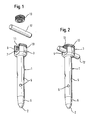
- Fig. 1 shows a perspective exploded view of a bone anchoring nail according to a first embodiment.
- Fig. 2 shows the bone anchoring nail according to Fig. 1 in an assembled state connected to a rod.
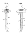
- Fig. 3 shows a side view of the bone anchoring nail with the rod according to the first embodiment in a direction along the rod axis.
- Fig. 4 shows a sectional view of the bone anchoring nail with the rod according to the first embodiment the section being taken along the rod axis.
- Fig. 5 shows an exploded perspective view of the bone anchoring nail according to a second embodiment.
- Fig. 6 shows the bone anchoring nail according to the second embodiment in an assembled state connected to a rod.
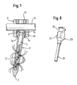
- Fig. 7 shows a sectional view of the bone anchoring nail of the second embodiment connected to a rod, the section be taken along the rod axis and a schematic view of the in-growth of vessels.
- Fig. 8 shows an injection device for injecting medical treatment agents or bone cement.
- a bone anchoring nail according to a first embodiment of the invention is described with reference to Fig. 1 to 4.
- the bone anchoring nail comprises a shaft 1 having a free end 2 and head 3 opposite to the free end 2.
- a coaxial bore 4 extends through the shaft from the end where the head 3 is located up to a distance from the free end 2. The diameter of the coaxial bore 4 is such that the shaft has sufficient strength against failure.
- a plurality of openings 5 extend in a radial direction from the bore 4 through the wall of the shaft 1 to the outside.
- the cross-section of the openings is preferably circular or otherwise rounded.
- the openings can be arranged in regular manner, such as, for example, in circumferential rows wherein one row is offset with regard to another row such as to provide a uniform distribution of openings in a section of the shaft 1.
- the number and arrangement of the openings is varied according to the clinical requirements.
- the diameter of the openings is at least as large that blood vessels from the surrounding bone material can grow-in followed by the formation of new bone into the openings.
- the diameter of the opening is selected such that bone cement and/or medical treatment agents can exit through the openings without clogging.
- a countersink area (not shown) around the openings can be provided to facilitate in-growth.
- the openings 5 are shown to extend in a radial direction with respect to the shaft axis M. However, some or all of them may also extend in a direction including an angle with the axial bore which is different from 90°.
- the length of the shaft is selected so as to be suitable for the specific application.
- the free end 2 is shaped as a tip. However, free end 2 also can be flat.
- the shaft 1 can taper to the free end 2 in a section 6, for example, it can taper in a conical shape.
- the coaxial bore 4 can also extend over the full length of the shaft 1 up to the free end 2 such that it provides an opening at the free end 2.
- the tip can be provided as a separate part connectable to the shaft 1. In this case, the coaxial bore 4 may be closed by connecting a separate tip to the shaft.
- the outer surface of the shaft 1 is threadless.
- the outer surface of the shaft 1 can be treated to provide an enhanced fixation or to enhance slidability of the shaft in the core hole.
- the outer surface can be roughened to enhance fixation or coated with a material promoting in-growth.
- the surface can be coated or polished or otherwise treated to enhance slidability to facilitate insertion.
- the head 3 is, in the embodiment shown, substantially cylindrically-shaped with an outer diameter which is larger than the diameter of the shaft 1.
- the head 3 comprises a substantially U-shaped recess 7 and a coaxial bore 8 which extends through the head and is in communication with the coaxial bore 4 of the shaft.
- two free legs 9, 10 are formed which are provided with an internal thread 11.
- the diameter of the U-shaped recess 7 is such that a rod 12, used for connecting several of the bone anchoring nails with each other, can be inserted.
- the rod 12 is secured by a locking element, for example by an inner screw 13 which can be screwed-in between the legs 9, 10 and which presses onto the rod.
- the head 3 and the shaft 1 are designed as a single part.
- the head 3 and the shaft 1 can also be designed as separate parts, wherein the head 3 and the shaft 1 can be rigidly connected with each other so as to form a rigid monoaxial connection.
- the head 3 and the shaft 1 can be rotatably connected, the rotation axis being the shaft axis.
- the locking element can be realized otherwise than by an inner screw 13.
- a combination of an outer nut which cooperates with an outer thread on the head 3 and an inner screw can be provided.
- another locking mechanism is conceivable, for example, a bayonet coupling between the locking element and the head.
- the bone anchoring nail is made of a biocompatible material, such as titanium or a titanium alloy or a biocompatible plastic material. It can also be made from a shape memory alloy.
- a core hole is prepared in the bone area where the bone anchoring nail is to be anchored.
- the inner diameter of the hole corresponds to the outer diameter of the shaft or is slightly smaller.
- the shaft 1 is then pushed or pressed into the core hole. If the shaft 1 is pressed into the core hole it holds due to the frictional forces.
- the action of inserting the shaft into the hole is considerably less time consuming than screwing a bone screw into the bone, even if a pre-drilled hole is used for the bone screw.
- the bone anchoring nail can be used in such clinical situations, in which a very quick insertion is necessary and/or in which weakness of the bone material does not allow the application of large insertion forces which may occur in the case of using a bone screw.
- the bone anchoring nail After inserting at least two bone anchoring nails they can be connected via the rod.
- the rod is fixed by tightening the inner screw.
- the bone anchoring nail can also be combined with conventional monoaxial bone screws which are used for connection with rods.
- blood vessels may begin to grow-in through the openings 5 into the coaxial bore 4 followed by the formation of new bone, thereby enhancing the fixation.
- a bone cement such as for example PMMA or TCP can be introduced through the bore 8 of the head and the longitudinal bore 4 of the shaft before inserting the rod.
- the bone cement is in a substantially fluid form and exits through the openings 5. When it hardens, it firmly connects the shaft 1 with the surrounding bone material.
- a second embodiment is shown in Fig. 5 to 7.
- the second embodiment differs from the first embodiment in that the head and the shaft are configured as separate parts which are pivotably connected so as to allow a polyaxial adjustment. Parts which are identical to the first embodiment are designated with the same reference numerals.
- the shaft 1' differs from the first embodiment in that it has a spherical segment-shaped end section 1a through which the longitudinal bore 4 extends. On its free end the spherical segment-shaped end section 1a comprises a recess 1b for engagement with a screwing-in tool.
- the head 3' is formed as a separate part. It has, like the head 3 of the first embodiment, a substantially cylindrical shape with a substantially U-shaped recess 7 and a coaxial bore 8 by means of which two legs 9, 10 are formed on which an internal thread 11 is provided.
- the head 3' has a lower side 3a with an opening 3b which is dimensioned such that spherical segment-shaped head 1a cannot fall out in the assembled state. Between the bore 8 and the opening 3b a seat 3c for the spherical segment-shaped end section 1a is provided. In the assembled state, the shaft 1' can pivot relative to the head 3'.
- the bone anchoring nail according to the second embodiment further comprises a pressure element 14 which is substantially cylindrically-shaped with a coaxial bore 15 and a spherical section 16 suitable to press on to the end section 1a.
- the pressure element 14 has a substantially U-shaped recess 17 opposite to the spherical section 16 for receiving the rod 12.
- the pressure element 14 can be secured within the head 3' against rotation and against falling out.
- the shaft 1', the head 3' and the pressure element 14 are preassembled.
- the bone anchoring nail according to the second embodiment allows a polyaxial adjustment of the head 3' with respect to the shaft 1'.
- the angular position of the shaft 1' relative to the head 3' is locked by pressing the pressure element 14 onto the spherical segment-shaped end section 1a which presses the spherical segment-shaped end section 1a against the seat 3c. Locking is accomplished by tightening the inner screw such that the rod 12 is fixed and transmits the force onto the pressure element 14 which then blocks the spherical segment-shaped end section 1a.
- the spherical segment-section 1a of the shaft 1' and the rod 12 can be locked independently from each other.
- Fig. 7 schematically shows the in-growth of blood vessels through the openings 5.
- the vessels extend through the openings and can further continue to grow in the coaxial bore 4.
- Fig. 8 schematically shows an injection instrument 20 for injecting bone cement or a medical treatment agent to the shaft 1, 1'.
- the injection instrument 20 comprises a reservoir 21 for the agent or the bone cement, an injection tube 22 and an actuator 23 for actuating the injection.
- the injection tube 22 has an outer diameter which is smaller than the diameter of the coaxial bore 4 such that it can be introduced to such an extent into the coaxial bore 4 that it reaches to the vicinity of the openings.
Abstract
a threadless shaft (1') with a free end (2),
a head (3') opposite to the free end, the head having a substantially U-shaped recess (7) for accommodation of a rod (12) or a rod-shaped element,
a longitudinal bore (4) extending through the shaft and opening towards at least the head (3') or the free end (2) and
a plurality of openings (5) extending through the wall of the shaft and being in communication with the bore (4). The bone anchoring nail allows quick insertion and reliable fixation enhanced by the in-growth of blood vessels.
Description
- The present invention relates to a bone anchoring nail. In particular, it relates to a bone anchoring nail having a shaft with a longitudinal bore and a plurality of openings in the wall of the shaft, and a head with a substantially U-shaped recess for accommodation of a rod. The bone anchoring nail can be used, for example, for anchoring a spinal rod in the ped-icles of adjacent vertebrae for stabilizing the spinal column or it can be used in any other type of bone anchor application using a rod or a rod-shaped element.
- A bone anchoring device in form of a bone screw comprising a screw head and a treaded shaft, wherein an axial bore is provided which is connected to the outside through a plurality of radial bores is known from
WO 01/26568 US 2004/0147929 A1 discloses a bone anchoring device having a tubular element having a section with a bone thread on its outer wall, a tip and a head which can be connected to the tubular element, wherein the head comprises a U-shaped recess for receiving a rod. The insertion of such a bone anchoring device is accomplished by screwing-in which is force and time consuming. Further, during screwing, forces act onto the bone which can be too large in certain situations, for example in the case of older and/or weak bones. -
US 2004/0220575 A1 discloses a bone anchoring element for anchoring an external device in the bone. The bone anchoring element comprises a head which is connectable to the external device and a shaft connected to the head, wherein the shaft has a predetermined section with a bone thread and at least one bone thread-free section within said predetermined section. The bone anchoring device can be pushed into a pre-drilled hole in the bone and then turned so as to allow anchoring by means of the bone thread. The anchoring device can be unscrewed due to the presence of the bone thread. In a specific embodiment the shaft comprises a longitudinal bore with radial bores leading to the outside for the purpose of allowing the introduction of a medical agent or bone cement into the pre-drilled hole. -
US 5,743,912 andJP 09149906 A -
US 2006/0089642 A1 describes an implant for vertebrae and other bones which is formed as an elongated cylindrical body with a series of perforations penetrating the cylinder wall and communicating with the cylinder bore. The bore may be filled with a bone growth mixture. The implant is not suitable for connection with a spinal stabilization rod. - For certain clinical requirements, in particular for the stabilisation of weak osteoporotic bone, in paediatric surgery, in surgery of the cervical spine or in neurosurgery, there is a need for bone anchoring devices which can be connected to an external stabilization rod or rod-shaped element, wherein the bone anchoring devices can be inserted even more quickly and with lower insertion forces than the known devices while providing a safe fixation which is comparable to that of screws.
- It is the object to provide such a bone anchoring device. The object is solved by a bone anchoring nail according to
claim 1. Further developments are given in the dependent claims. - The bone anchoring nail according to the invention allows a fast insertion into a core hole which is provided in the bone in advance. A reliable and lasting fixation is accomplished by ingrowth of vessels into the openings followed by newly formed bone into the openings and/or by the injection of bone cement through the longitudinal bore which exits through the openings, hardens and connects the nail to the surrounding bone material.
- The bone anchoring nail is specifically applicable to minimally invasive surgery (MIS), to spinal surgery and to the stabilization of long bones.
- Further features and advantages of the invention will become apparent and will be best understood by reference to the following detailed description of embodiments taken in conjunction with the accompanying drawings.
- Fig. 1 shows a perspective exploded view of a bone anchoring nail according to a first embodiment.
- Fig. 2 shows the bone anchoring nail according to Fig. 1 in an assembled state connected to a rod.
- Fig. 3 shows a side view of the bone anchoring nail with the rod according to the first embodiment in a direction along the rod axis.
- Fig. 4 shows a sectional view of the bone anchoring nail with the rod according to the first embodiment the section being taken along the rod axis.
- Fig. 5 shows an exploded perspective view of the bone anchoring nail according to a second embodiment.
- Fig. 6 shows the bone anchoring nail according to the second embodiment in an assembled state connected to a rod.
- Fig. 7 shows a sectional view of the bone anchoring nail of the second embodiment connected to a rod, the section be taken along the rod axis and a schematic view of the in-growth of vessels.
- Fig. 8 shows an injection device for injecting medical treatment agents or bone cement.
- A bone anchoring nail according to a first embodiment of the invention is described with reference to Fig. 1 to 4. The bone anchoring nail comprises a
shaft 1 having afree end 2 andhead 3 opposite to thefree end 2. Acoaxial bore 4 extends through the shaft from the end where thehead 3 is located up to a distance from thefree end 2. The diameter of thecoaxial bore 4 is such that the shaft has sufficient strength against failure. - A plurality of
openings 5 extend in a radial direction from thebore 4 through the wall of theshaft 1 to the outside. The cross-section of the openings is preferably circular or otherwise rounded. The openings can be arranged in regular manner, such as, for example, in circumferential rows wherein one row is offset with regard to another row such as to provide a uniform distribution of openings in a section of theshaft 1. As shown in the drawings, there can be a section of theshaft 1 which is adjacent to thehead 3 where no openings are provided. The number and arrangement of the openings is varied according to the clinical requirements. The diameter of the openings is at least as large that blood vessels from the surrounding bone material can grow-in followed by the formation of new bone into the openings. Also, the diameter of the opening is selected such that bone cement and/or medical treatment agents can exit through the openings without clogging. At the outer wall of theshaft 1 a countersink area (not shown) around the openings can be provided to facilitate in-growth. Theopenings 5 are shown to extend in a radial direction with respect to the shaft axis M. However, some or all of them may also extend in a direction including an angle with the axial bore which is different from 90°. The length of the shaft is selected so as to be suitable for the specific application. - The
free end 2 is shaped as a tip. However,free end 2 also can be flat. Theshaft 1 can taper to thefree end 2 in asection 6, for example, it can taper in a conical shape. Thecoaxial bore 4 can also extend over the full length of theshaft 1 up to thefree end 2 such that it provides an opening at thefree end 2. Also, the tip can be provided as a separate part connectable to theshaft 1. In this case, thecoaxial bore 4 may be closed by connecting a separate tip to the shaft. - As shown in the figures, the outer surface of the
shaft 1 is threadless. In addition, the outer surface of theshaft 1 can be treated to provide an enhanced fixation or to enhance slidability of the shaft in the core hole. For example, the outer surface can be roughened to enhance fixation or coated with a material promoting in-growth. In another example, the surface can be coated or polished or otherwise treated to enhance slidability to facilitate insertion. - The
head 3 is, in the embodiment shown, substantially cylindrically-shaped with an outer diameter which is larger than the diameter of theshaft 1. Thehead 3 comprises a substantiallyU-shaped recess 7 and acoaxial bore 8 which extends through the head and is in communication with thecoaxial bore 4 of the shaft. By means of the U-shaped recess 7 twofree legs internal thread 11. The diameter of the U-shapedrecess 7 is such that arod 12, used for connecting several of the bone anchoring nails with each other, can be inserted. Therod 12 is secured by a locking element, for example by aninner screw 13 which can be screwed-in between thelegs - In the embodiment shown the
head 3 and theshaft 1 are designed as a single part. However, thehead 3 and theshaft 1 can also be designed as separate parts, wherein thehead 3 and theshaft 1 can be rigidly connected with each other so as to form a rigid monoaxial connection. Alternatively, thehead 3 and theshaft 1 can be rotatably connected, the rotation axis being the shaft axis. - The locking element can be realized otherwise than by an
inner screw 13. For example, a combination of an outer nut which cooperates with an outer thread on thehead 3 and an inner screw can be provided. Alternatively, another locking mechanism is conceivable, for example, a bayonet coupling between the locking element and the head. - The bone anchoring nail is made of a biocompatible material, such as titanium or a titanium alloy or a biocompatible plastic material. It can also be made from a shape memory alloy.
- In operation, first, a core hole is prepared in the bone area where the bone anchoring nail is to be anchored. The inner diameter of the hole corresponds to the outer diameter of the shaft or is slightly smaller. The
shaft 1 is then pushed or pressed into the core hole. If theshaft 1 is pressed into the core hole it holds due to the frictional forces. The action of inserting the shaft into the hole is considerably less time consuming than screwing a bone screw into the bone, even if a pre-drilled hole is used for the bone screw. Hence, the bone anchoring nail can be used in such clinical situations, in which a very quick insertion is necessary and/or in which weakness of the bone material does not allow the application of large insertion forces which may occur in the case of using a bone screw. - After inserting at least two bone anchoring nails they can be connected via the rod. The rod is fixed by tightening the inner screw. The bone anchoring nail can also be combined with conventional monoaxial bone screws which are used for connection with rods.
- After some time blood vessels may begin to grow-in through the
openings 5 into thecoaxial bore 4 followed by the formation of new bone, thereby enhancing the fixation. - For further enhancing the fixation a bone cement such as for example PMMA or TCP can be introduced through the
bore 8 of the head and thelongitudinal bore 4 of the shaft before inserting the rod. The bone cement is in a substantially fluid form and exits through theopenings 5. When it hardens, it firmly connects theshaft 1 with the surrounding bone material. - A second embodiment is shown in Fig. 5 to 7. The second embodiment differs from the first embodiment in that the head and the shaft are configured as separate parts which are pivotably connected so as to allow a polyaxial adjustment. Parts which are identical to the first embodiment are designated with the same reference numerals. The shaft 1' differs from the first embodiment in that it has a spherical segment-shaped
end section 1a through which thelongitudinal bore 4 extends. On its free end the spherical segment-shapedend section 1a comprises arecess 1b for engagement with a screwing-in tool. - The head 3' is formed as a separate part. It has, like the
head 3 of the first embodiment, a substantially cylindrical shape with a substantiallyU-shaped recess 7 and acoaxial bore 8 by means of which twolegs internal thread 11 is provided. The head 3' has alower side 3a with anopening 3b which is dimensioned such that spherical segment-shapedhead 1a cannot fall out in the assembled state. Between thebore 8 and theopening 3b aseat 3c for the spherical segment-shapedend section 1a is provided. In the assembled state, the shaft 1' can pivot relative to the head 3'. - The bone anchoring nail according to the second embodiment further comprises a
pressure element 14 which is substantially cylindrically-shaped with acoaxial bore 15 and aspherical section 16 suitable to press on to theend section 1a. In the embodiment shown thepressure element 14 has a substantiallyU-shaped recess 17 opposite to thespherical section 16 for receiving therod 12. Thepressure element 14 can be secured within the head 3' against rotation and against falling out. Preferably, the shaft 1', the head 3' and thepressure element 14 are preassembled. - Use of the bone anchoring nail according to the second embodiment is similar to that of the first embodiment. The bone anchoring nail according to the second embodiment allows a polyaxial adjustment of the head 3' with respect to the shaft 1'. The angular position of the shaft 1' relative to the head 3' is locked by pressing the
pressure element 14 onto the spherical segment-shapedend section 1a which presses the spherical segment-shapedend section 1a against theseat 3c. Locking is accomplished by tightening the inner screw such that therod 12 is fixed and transmits the force onto thepressure element 14 which then blocks the spherical segment-shapedend section 1a. - In a modification, the spherical segment-
section 1a of the shaft 1' and therod 12 can be locked independently from each other. - Fig. 7 schematically shows the in-growth of blood vessels through the
openings 5. The vessels extend through the openings and can further continue to grow in thecoaxial bore 4. - Fig. 8 schematically shows an
injection instrument 20 for injecting bone cement or a medical treatment agent to theshaft 1, 1'. Theinjection instrument 20 comprises areservoir 21 for the agent or the bone cement, aninjection tube 22 and anactuator 23 for actuating the injection. Theinjection tube 22 has an outer diameter which is smaller than the diameter of thecoaxial bore 4 such that it can be introduced to such an extent into thecoaxial bore 4 that it reaches to the vicinity of the openings.
Claims (10)
- Bone anchoring nail having
a threadless shaft (1, 1') with a free end (2),
a head (3, 3') opposite to the free end, the head having a substantially U-shaped recess (7) for accommodation of a rod (12) or a rod-shaped element,
a longitudinal bore (4) extending through the shaft and opening towards at least the head (3, 3') or the free end (2) and a plurality of openings (5) extending through the wall of the shaft and being in communication with the bore (4). - The bone anchoring nail of claim 1, wherein the bore (4) is open towards the head (3, 3') and closed at the second end end (2).
- The bone anchoring nail of claim 1 or 2, wherein the shaft has a substantially cylindrical shape.
- The bone anchoring nail of one of claims 1 to 3, wherein the openings (5) have a round cross-section.
- The bone anchoring nail of one of claims 1 to 4, wherein the openings (5) extend in a radial direction from the shaft axis (M).
- The bone anchoring nail of one of claims 1 to 5, wherein the outer surface of the shaft is treated such as roughened or coated to enhance fixation.
- The bone anchoring nail of one of claims 1 to 6, wherein the shaft (1) and the head (3) are mono-axially connected.
- The bone anchoring nail of one of claims 1 to 6, wherein the shaft (1') has a spherical segment-shaped end section (1a) and the head (3') is a separate part which is provided with a seat (3c) for pivotably holding the end section.
- The bone anchoring nail according to claim 8, wherein a pressure element (14) is provided between the rod (12) and the end section (1a), the pressure element locking the end section (1a) against the seat (3c) when pressure is exerted.
- The bone anchoring nail of one of claims 1 to 9, wherein a locking element (13) for locking the rod (12) or the rod-shaped element in the recess (7) is provided, the locking element cooperating with the head (3, 3').
Priority Applications (12)
| Application Number | Priority Date | Filing Date | Title |
|---|---|---|---|
| EP06023443A EP1920722B1 (en) | 2006-11-10 | 2006-11-10 | Bone anchoring nail |
| ES06023443T ES2328841T3 (en) | 2006-11-10 | 2006-11-10 | OSEO ANCHORAGE NAIL. |
| DE602006007475T DE602006007475D1 (en) | 2006-11-10 | 2006-11-10 | Bone anchoring nail |
| US11/870,326 US7785356B2 (en) | 2006-11-10 | 2007-10-10 | Bone anchoring nail |
| TW096141778A TWI417079B (en) | 2006-11-10 | 2007-11-06 | Bone anchoring nail |
| JP2007288616A JP2008119467A (en) | 2006-11-10 | 2007-11-06 | Bone anchoring nail |
| CN2007101850408A CN101176680B (en) | 2006-11-10 | 2007-11-06 | Bone anchoring nail |
| KR1020070112646A KR101538135B1 (en) | 2006-11-10 | 2007-11-06 | Bone Anchoring Nail |
| US12/844,588 US8206424B2 (en) | 2006-11-10 | 2010-07-27 | Bone anchoring nail |
| US13/479,041 US20120283791A1 (en) | 2006-11-10 | 2012-05-23 | Bone anchoring nail |
| JP2013031045A JP2013090987A (en) | 2006-11-10 | 2013-02-20 | Bone anchoring nail |
| US13/789,271 US9517088B2 (en) | 2006-11-10 | 2013-03-07 | Bone anchoring nail |
Applications Claiming Priority (1)
| Application Number | Priority Date | Filing Date | Title |
|---|---|---|---|
| EP06023443A EP1920722B1 (en) | 2006-11-10 | 2006-11-10 | Bone anchoring nail |
Publications (2)
| Publication Number | Publication Date |
|---|---|
| EP1920722A1 true EP1920722A1 (en) | 2008-05-14 |
| EP1920722B1 EP1920722B1 (en) | 2009-06-24 |
Family
ID=37964885
Family Applications (1)
| Application Number | Title | Priority Date | Filing Date |
|---|---|---|---|
| EP06023443A Active EP1920722B1 (en) | 2006-11-10 | 2006-11-10 | Bone anchoring nail |
Country Status (6)
| Country | Link |
|---|---|
| US (4) | US7785356B2 (en) |
| EP (1) | EP1920722B1 (en) |
| CN (1) | CN101176680B (en) |
| DE (1) | DE602006007475D1 (en) |
| ES (1) | ES2328841T3 (en) |
| TW (1) | TWI417079B (en) |
Cited By (3)
| Publication number | Priority date | Publication date | Assignee | Title |
|---|---|---|---|---|
| EP2140824A1 (en) * | 2008-07-01 | 2010-01-06 | BIEDERMANN MOTECH GmbH | Cannulated bone anchor with plug member and tool for inserting the plug member into the bone anchor |
| CN103040515A (en) * | 2012-12-27 | 2013-04-17 | 苏州欣荣博尔特医疗器械有限公司 | Multi-axial spinal screw |
| EP3081181A4 (en) * | 2013-10-10 | 2017-03-01 | Dongguan Eontec Co., Ltd. | Biodegradable pure magnesium bone nail |
Families Citing this family (32)
| Publication number | Priority date | Publication date | Assignee | Title |
|---|---|---|---|---|
| US7722620B2 (en) | 2004-12-06 | 2010-05-25 | Dfine, Inc. | Bone treatment systems and methods |
| CA2626437A1 (en) * | 2005-11-10 | 2007-05-24 | Zimmer, Inc. | Minamally invasive orthopaedic delivery devices and tools |
| ES2328841T3 (en) * | 2006-11-10 | 2009-11-18 | Biedermann Motech Gmbh | OSEO ANCHORAGE NAIL. |
| US9597118B2 (en) * | 2007-07-20 | 2017-03-21 | Dfine, Inc. | Bone anchor apparatus and method |
| US8998958B2 (en) * | 2007-12-20 | 2015-04-07 | Aesculap Implant Systems, Llc | Locking device introducer instrument |
| US20090281581A1 (en) * | 2008-05-06 | 2009-11-12 | Berg Jeffery H | Method and device for securing sutures to bones |
| US8303589B2 (en) | 2008-06-24 | 2012-11-06 | Extremity Medical Llc | Fixation system, an intramedullary fixation assembly and method of use |
| US20110230884A1 (en) * | 2008-06-24 | 2011-09-22 | Adam Mantzaris | Hybrid intramedullary fixation assembly and method of use |
| US8313487B2 (en) | 2008-06-24 | 2012-11-20 | Extremity Medical Llc | Fixation system, an intramedullary fixation assembly and method of use |
| US8343199B2 (en) | 2008-06-24 | 2013-01-01 | Extremity Medical, Llc | Intramedullary fixation screw, a fixation system, and method of fixation of the subtalar joint |
| US9289220B2 (en) | 2008-06-24 | 2016-03-22 | Extremity Medical Llc | Intramedullary fixation assembly and method of use |
| US9044282B2 (en) | 2008-06-24 | 2015-06-02 | Extremity Medical Llc | Intraosseous intramedullary fixation assembly and method of use |
| US8328806B2 (en) | 2008-06-24 | 2012-12-11 | Extremity Medical, Llc | Fixation system, an intramedullary fixation assembly and method of use |
| US9017329B2 (en) | 2008-06-24 | 2015-04-28 | Extremity Medical, Llc | Intramedullary fixation assembly and method of use |
| CN102271731B (en) | 2008-10-30 | 2015-11-25 | 德普伊斯派尔公司 | For sending the system and method for bone cement to bone anchors |
| WO2010123859A2 (en) * | 2009-04-20 | 2010-10-28 | Osteo Innovations Llc | System and method for self filling bone screws |
| US20110112579A1 (en) * | 2009-10-28 | 2011-05-12 | Declan Patrick Brazil | Rod and method of insertion |
| ES2620481T3 (en) * | 2009-11-09 | 2017-06-28 | Spinewelding Ag | Medical device, device |
| ES2456317T3 (en) * | 2010-02-26 | 2014-04-22 | Biedermann Technologies Gmbh & Co. Kg | Bone screw |
| CN101966098B (en) * | 2010-10-08 | 2012-07-25 | 陆宁 | Perfusion type pedicle screw |
| US20120123481A1 (en) * | 2010-11-15 | 2012-05-17 | Lin Chih I | Bone fixation device |
| WO2013010283A2 (en) | 2011-07-18 | 2013-01-24 | Sportwelding Gmbh | Method of fastening a soft tissue graft in an opening provided in a human or animal bone and fastener suitable for the method |
| US9655655B2 (en) | 2011-08-16 | 2017-05-23 | Aesculap Implant Systems, Llc | Two step locking screw assembly |
| US9155580B2 (en) | 2011-08-25 | 2015-10-13 | Medos International Sarl | Multi-threaded cannulated bone anchors |
| TWI491377B (en) * | 2012-07-10 | 2015-07-11 | 國立中山大學 | Bone implant |
| US9101426B2 (en) | 2012-10-11 | 2015-08-11 | Stryker Trauma Sa | Cable plug |
| US10499968B2 (en) | 2014-08-08 | 2019-12-10 | Stryker European Holdings I, Llc | Cable plugs for bone plates |
| DE202015003062U1 (en) * | 2015-04-25 | 2016-07-27 | Silony Medical International AG | Monoaxialknochenschraube |
| US10426455B2 (en) * | 2016-02-04 | 2019-10-01 | Westek, LLC | Surgical anchor and method of use |
| CN106871809A (en) * | 2017-03-28 | 2017-06-20 | 智性科技南通有限公司 | A kind of replaceable fatigue fiber Bragg grating strain sensor high |
| US11147602B2 (en) * | 2017-05-04 | 2021-10-19 | Warsaw Orthopedic, Inc. | Spinal implant system and method |
| US10765461B2 (en) * | 2018-06-01 | 2020-09-08 | DePuy Synthes Products, Inc. | Variable angle bone fixation device |
Citations (4)
| Publication number | Priority date | Publication date | Assignee | Title |
|---|---|---|---|---|
| EP0784967A2 (en) * | 1996-01-19 | 1997-07-23 | Howmedica GmbH | Spine implant |
| EP1430846A1 (en) * | 2002-12-20 | 2004-06-23 | BIEDERMANN MOTECH GmbH | Tubular element for implant for spinal or bone surgery |
| US20050059972A1 (en) * | 2003-09-16 | 2005-03-17 | Spineco, Inc., An Ohio Corporation | Bone anchor prosthesis and system |
| WO2006070961A2 (en) * | 2004-12-31 | 2006-07-06 | Ji-Hoon Her | Pedicle screw and device for injecting bone cement into bone |
Family Cites Families (23)
| Publication number | Priority date | Publication date | Assignee | Title |
|---|---|---|---|---|
| JP3049906B2 (en) | 1992-01-24 | 2000-06-05 | 松下電器産業株式会社 | Antibacterial resin |
| CA2130083A1 (en) | 1992-02-14 | 1993-08-19 | Acufex Microsurgical, Inc. | Polymeric screws and coatings for surgical uses |
| JPH0751292A (en) | 1993-08-16 | 1995-02-28 | Yoshihiro Kishigami | Bone screw left in bone |
| DE4425357C2 (en) | 1994-07-18 | 1996-07-04 | Harms Juergen | Anchoring element |
| FR2726171B1 (en) | 1994-10-28 | 1997-01-24 | Jbs Sa | REHABITABLE CONNECTING SCREW DEVICE FOR BONE JOINT, IN PARTICULAR FOR STABILIZING AT LEAST TWO VERTEBRES |
| FR2737968B1 (en) * | 1995-08-23 | 1997-12-05 | Biomat | IMPLANT FOR OSTEOSYNTHESIS OF SUPERIOR FEMALE EPIPHYSIS |
| JPH09149906A (en) | 1995-11-29 | 1997-06-10 | Nagoya Rashi Seisakusho:Kk | Tool for curing bone disease |
| US6214012B1 (en) * | 1998-11-13 | 2001-04-10 | Harrington Arthritis Research Center | Method and apparatus for delivering material to a desired location |
| DE19949285C2 (en) | 1999-10-12 | 2002-08-14 | Impag Gmbh Medizintechnik | bone screw |
| US6648889B2 (en) * | 2001-04-24 | 2003-11-18 | Dale G. Bramlet | Intramedullary hip nail with bifurcated lock |
| DE10157969C1 (en) | 2001-11-27 | 2003-02-06 | Biedermann Motech Gmbh | Element used in spinal and accident surgery comprises a shaft joined to a holding element having a U-shaped recess with two free arms having an internal thread with flanks lying at right angles to the central axis of the holding element |
| CN1432343A (en) * | 2002-01-17 | 2003-07-30 | 英属维京群岛商冠亚生技控股集团股份有限公司 | Rotary controlled vertebra fixture |
| DE10246177A1 (en) | 2002-10-02 | 2004-04-22 | Biedermann Motech Gmbh | Anchor element consists of screw with head, bone-thread section on shank and holder joining rod-shaped part to screw. with cavities in wall, and thread-free end of shank |
| DE10319781B3 (en) | 2003-04-30 | 2004-08-26 | Biedermann Motech Gmbh | Bone anchor, to attach a component to the bone, has a head to hold the component and a shaft with screw thread sections and thread-free sections along the shaft length |
| US7833256B2 (en) * | 2004-04-16 | 2010-11-16 | Biedermann Motech Gmbh | Elastic element for the use in a stabilization device for bones and vertebrae and method for the manufacture of such elastic element |
| JP4242855B2 (en) | 2004-07-27 | 2009-03-25 | KiSCO株式会社 | Implant for fixation |
| US20060058788A1 (en) * | 2004-08-27 | 2006-03-16 | Hammer Michael A | Multi-axial connection system |
| KR200367241Y1 (en) | 2004-08-27 | 2004-11-10 | 진동규 | Spinal fixation apparatus |
| US20060089642A1 (en) | 2004-10-27 | 2006-04-27 | Diaz Robert L | Prefracture spinal implant for osteoporotic unfractured bone |
| US20060241593A1 (en) * | 2005-04-08 | 2006-10-26 | Sdgi Holdings, Inc. | Multi-piece vertebral attachment device |
| WO2007073743A1 (en) * | 2005-12-15 | 2007-07-05 | Tissuedent Gmbh & Co. Kg | Implant for fixing in bone |
| US8372126B2 (en) * | 2006-04-21 | 2013-02-12 | Warsaw Orthopedic, Inc. | Surgical fasteners with mechanical and osteogenic fixation means |
| ES2328841T3 (en) * | 2006-11-10 | 2009-11-18 | Biedermann Motech Gmbh | OSEO ANCHORAGE NAIL. |
-
2006
- 2006-11-10 ES ES06023443T patent/ES2328841T3/en active Active
- 2006-11-10 EP EP06023443A patent/EP1920722B1/en active Active
- 2006-11-10 DE DE602006007475T patent/DE602006007475D1/en active Active
-
2007
- 2007-10-10 US US11/870,326 patent/US7785356B2/en active Active
- 2007-11-06 CN CN2007101850408A patent/CN101176680B/en not_active Expired - Fee Related
- 2007-11-06 TW TW096141778A patent/TWI417079B/en not_active IP Right Cessation
-
2010
- 2010-07-27 US US12/844,588 patent/US8206424B2/en active Active
-
2012
- 2012-05-23 US US13/479,041 patent/US20120283791A1/en not_active Abandoned
-
2013
- 2013-03-07 US US13/789,271 patent/US9517088B2/en active Active
Patent Citations (4)
| Publication number | Priority date | Publication date | Assignee | Title |
|---|---|---|---|---|
| EP0784967A2 (en) * | 1996-01-19 | 1997-07-23 | Howmedica GmbH | Spine implant |
| EP1430846A1 (en) * | 2002-12-20 | 2004-06-23 | BIEDERMANN MOTECH GmbH | Tubular element for implant for spinal or bone surgery |
| US20050059972A1 (en) * | 2003-09-16 | 2005-03-17 | Spineco, Inc., An Ohio Corporation | Bone anchor prosthesis and system |
| WO2006070961A2 (en) * | 2004-12-31 | 2006-07-06 | Ji-Hoon Her | Pedicle screw and device for injecting bone cement into bone |
Cited By (8)
| Publication number | Priority date | Publication date | Assignee | Title |
|---|---|---|---|---|
| EP2140824A1 (en) * | 2008-07-01 | 2010-01-06 | BIEDERMANN MOTECH GmbH | Cannulated bone anchor with plug member and tool for inserting the plug member into the bone anchor |
| EP2687173A1 (en) * | 2008-07-01 | 2014-01-22 | Biedermann Technologies GmbH & Co. KG | Bone anchor with plug member and tool for inserting the plug member into the bone anchor |
| US8690930B2 (en) | 2008-07-01 | 2014-04-08 | Biedermann Technologies Gmbh & Co. Kg | Bone anchor with plug member and tool for inserting the plug member into the bone anchor |
| CN101617953B (en) * | 2008-07-01 | 2014-10-29 | 比德尔曼技术有限责任两合公司 | Cannulated bone anchor with plug member and tool for inserting the plug member into the bone anchor |
| US9265539B2 (en) | 2008-07-01 | 2016-02-23 | Biedermann Technologies Gmbh & Co. Kg | Bone anchor with plug member and tool for inserting the plug member into the bone anchor |
| US9730745B2 (en) | 2008-07-01 | 2017-08-15 | Biedermann Technologies Gmbh & Co. Kg | Bone anchor with plug member and tool for inserting the plug member into the bone anchor |
| CN103040515A (en) * | 2012-12-27 | 2013-04-17 | 苏州欣荣博尔特医疗器械有限公司 | Multi-axial spinal screw |
| EP3081181A4 (en) * | 2013-10-10 | 2017-03-01 | Dongguan Eontec Co., Ltd. | Biodegradable pure magnesium bone nail |
Also Published As
| Publication number | Publication date |
|---|---|
| US7785356B2 (en) | 2010-08-31 |
| ES2328841T3 (en) | 2009-11-18 |
| TWI417079B (en) | 2013-12-01 |
| TW200820934A (en) | 2008-05-16 |
| US20120283791A1 (en) | 2012-11-08 |
| DE602006007475D1 (en) | 2009-08-06 |
| US9517088B2 (en) | 2016-12-13 |
| EP1920722B1 (en) | 2009-06-24 |
| US20100292741A1 (en) | 2010-11-18 |
| US8206424B2 (en) | 2012-06-26 |
| CN101176680A (en) | 2008-05-14 |
| US20130184761A1 (en) | 2013-07-18 |
| CN101176680B (en) | 2011-06-08 |
| US20080132956A1 (en) | 2008-06-05 |
Similar Documents
| Publication | Publication Date | Title |
|---|---|---|
| EP1920722B1 (en) | Bone anchoring nail | |
| EP2299921B1 (en) | Posterior spinal fastener | |
| US9730745B2 (en) | Bone anchor with plug member and tool for inserting the plug member into the bone anchor | |
| JP6087356B2 (en) | Bone anchor | |
| US9326800B2 (en) | Device for the cement augmentation of bone implants | |
| US6554830B1 (en) | Fenestrated surgical anchor and method | |
| US20080183223A1 (en) | Hybrid jointed bone screw system | |
| MX2011001810A (en) | Dynamic pedicle screw. | |
| JP2013090987A (en) | Bone anchoring nail | |
| WO2019046893A1 (en) | Cannulated fixation device | |
| US11426222B2 (en) | Osseous anchoring implant with optimized expansion |
Legal Events
| Date | Code | Title | Description |
|---|---|---|---|
| PUAI | Public reference made under article 153(3) epc to a published international application that has entered the european phase |
Free format text: ORIGINAL CODE: 0009012 |
|
| AK | Designated contracting states |
Kind code of ref document: A1 Designated state(s): AT BE BG CH CY CZ DE DK EE ES FI FR GB GR HU IE IS IT LI LT LU LV MC NL PL PT RO SE SI SK TR |
|
| AX | Request for extension of the european patent |
Extension state: AL BA HR MK RS |
|
| 17P | Request for examination filed |
Effective date: 20080521 |
|
| AKX | Designation fees paid |
Designated state(s): CH DE ES FR GB IT LI |
|
| GRAP | Despatch of communication of intention to grant a patent |
Free format text: ORIGINAL CODE: EPIDOSNIGR1 |
|
| GRAS | Grant fee paid |
Free format text: ORIGINAL CODE: EPIDOSNIGR3 |
|
| GRAA | (expected) grant |
Free format text: ORIGINAL CODE: 0009210 |
|
| AK | Designated contracting states |
Kind code of ref document: B1 Designated state(s): CH DE ES FR GB IT LI |
|
| REG | Reference to a national code |
Ref country code: GB Ref legal event code: FG4D |
|
| REG | Reference to a national code |
Ref country code: CH Ref legal event code: EP |
|
| REG | Reference to a national code |
Ref country code: CH Ref legal event code: NV Representative=s name: NOVAGRAAF INTERNATIONAL SA |
|
| REF | Corresponds to: |
Ref document number: 602006007475 Country of ref document: DE Date of ref document: 20090806 Kind code of ref document: P |
|
| REG | Reference to a national code |
Ref country code: ES Ref legal event code: FG2A Ref document number: 2328841 Country of ref document: ES Kind code of ref document: T3 |
|
| PLBE | No opposition filed within time limit |
Free format text: ORIGINAL CODE: 0009261 |
|
| STAA | Information on the status of an ep patent application or granted ep patent |
Free format text: STATUS: NO OPPOSITION FILED WITHIN TIME LIMIT |
|
| 26N | No opposition filed |
Effective date: 20100325 |
|
| REG | Reference to a national code |
Ref country code: CH Ref legal event code: PFA Owner name: BIEDERMANN MOTECH GMBH Free format text: BIEDERMANN MOTECH GMBH#BERTA-SUTTNER-STRASSE 23#78054 VILLINGEN-SCHWENNINGEN (DE) -TRANSFER TO- BIEDERMANN MOTECH GMBH#BERTA-SUTTNER-STRASSE 23#78054 VILLINGEN-SCHWENNINGEN (DE) |
|
| REG | Reference to a national code |
Ref country code: DE Ref legal event code: R082 Ref document number: 602006007475 Country of ref document: DE Representative=s name: PRUEFER & PARTNER GBR, DE |
|
| REG | Reference to a national code |
Ref country code: DE Ref legal event code: R082 Ref document number: 602006007475 Country of ref document: DE Representative=s name: PRUEFER & PARTNER GBR, DE Effective date: 20121128 Ref country code: DE Ref legal event code: R081 Ref document number: 602006007475 Country of ref document: DE Owner name: BIEDERMANN TECHNOLOGIES GMBH & CO. KG, DE Free format text: FORMER OWNER: BIEDERMANN MOTECH GMBH, 78054 VILLINGEN-SCHWENNINGEN, DE Effective date: 20121128 Ref country code: DE Ref legal event code: R082 Ref document number: 602006007475 Country of ref document: DE Representative=s name: PRUEFER & PARTNER MBB PATENTANWAELTE RECHTSANW, DE Effective date: 20121128 |
|
| REG | Reference to a national code |
Ref country code: CH Ref legal event code: PFA Owner name: BIEDERMANN MOTECH GMBH AND CO. KG, DE Free format text: FORMER OWNER: BIEDERMANN MOTECH GMBH, DE Ref country code: CH Ref legal event code: PUE Owner name: BIEDERMANN TECHNOLOGIES GMBH AND CO. KG, DE Free format text: FORMER OWNER: BIEDERMANN MOTECH GMBH AND CO. KG, DE |
|
| REG | Reference to a national code |
Ref country code: CH Ref legal event code: PFA Owner name: BIEDERMANN MOTECH GMBH AND CO. KG, DE Free format text: FORMER OWNER: BIEDERMANN MOTECH GMBH, DE Ref country code: ES Ref legal event code: PC2A Owner name: BIEDERMANN MOTECH GMBH & CO.KG. Effective date: 20130205 Ref country code: CH Ref legal event code: PUE Owner name: BIEDERMANN TECHNOLOGIES GMBH AND CO. KG, DE Free format text: FORMER OWNER: BIEDERMANN MOTECH GMBH AND CO. KG, DE |
|
| REG | Reference to a national code |
Ref country code: ES Ref legal event code: PC2A Owner name: BIEDERMANN TECHNOLOGIES GMBH & CO. KG Effective date: 20130311 |
|
| REG | Reference to a national code |
Ref country code: GB Ref legal event code: 732E Free format text: REGISTERED BETWEEN 20130307 AND 20130313 |
|
| REG | Reference to a national code |
Ref country code: FR Ref legal event code: CD Owner name: BIEDERMANN TECHNOLOGIES GMBH & CO.KG, DE Effective date: 20130329 Ref country code: FR Ref legal event code: TP Owner name: BIEDERMANN TECHNOLOGIES GMBH & CO.KG, DE Effective date: 20130329 |
|
| REG | Reference to a national code |
Ref country code: FR Ref legal event code: PLFP Year of fee payment: 10 |
|
| REG | Reference to a national code |
Ref country code: FR Ref legal event code: PLFP Year of fee payment: 11 |
|
| PGFP | Annual fee paid to national office [announced via postgrant information from national office to epo] |
Ref country code: FR Payment date: 20161124 Year of fee payment: 11 |
|
| PGFP | Annual fee paid to national office [announced via postgrant information from national office to epo] |
Ref country code: ES Payment date: 20161124 Year of fee payment: 11 Ref country code: IT Payment date: 20161124 Year of fee payment: 11 |
|
| REG | Reference to a national code |
Ref country code: FR Ref legal event code: ST Effective date: 20180731 |
|
| PG25 | Lapsed in a contracting state [announced via postgrant information from national office to epo] |
Ref country code: IT Free format text: LAPSE BECAUSE OF NON-PAYMENT OF DUE FEES Effective date: 20171110 Ref country code: FR Free format text: LAPSE BECAUSE OF NON-PAYMENT OF DUE FEES Effective date: 20171130 |
|
| REG | Reference to a national code |
Ref country code: ES Ref legal event code: FD2A Effective date: 20181226 |
|
| PG25 | Lapsed in a contracting state [announced via postgrant information from national office to epo] |
Ref country code: ES Free format text: LAPSE BECAUSE OF NON-PAYMENT OF DUE FEES Effective date: 20171111 |
|
| PGFP | Annual fee paid to national office [announced via postgrant information from national office to epo] |
Ref country code: GB Payment date: 20221123 Year of fee payment: 17 Ref country code: DE Payment date: 20221125 Year of fee payment: 17 |
|
| PGFP | Annual fee paid to national office [announced via postgrant information from national office to epo] |
Ref country code: CH Payment date: 20221124 Year of fee payment: 17 |
|
| P01 | Opt-out of the competence of the unified patent court (upc) registered |
Effective date: 20230525 |