EP1921520A1 - Drive module incorporating an MEMS micromotor, manufacturing process for this module, and time piece equipped with this module - Google Patents
Drive module incorporating an MEMS micromotor, manufacturing process for this module, and time piece equipped with this module Download PDFInfo
- Publication number
- EP1921520A1 EP1921520A1 EP06123973A EP06123973A EP1921520A1 EP 1921520 A1 EP1921520 A1 EP 1921520A1 EP 06123973 A EP06123973 A EP 06123973A EP 06123973 A EP06123973 A EP 06123973A EP 1921520 A1 EP1921520 A1 EP 1921520A1
- Authority
- EP
- European Patent Office
- Prior art keywords
- rotor
- plate
- drive module
- module
- zone
- Prior art date
- Legal status (The legal status is an assumption and is not a legal conclusion. Google has not performed a legal analysis and makes no representation as to the accuracy of the status listed.)
- Granted
Links
- 238000004519 manufacturing process Methods 0.000 title claims description 6
- 230000002093 peripheral effect Effects 0.000 claims abstract description 19
- 229910052710 silicon Inorganic materials 0.000 claims abstract description 18
- 239000010703 silicon Substances 0.000 claims abstract description 18
- 239000000758 substrate Substances 0.000 claims description 11
- 239000000463 material Substances 0.000 claims description 8
- 238000005530 etching Methods 0.000 claims description 5
- XUIMIQQOPSSXEZ-UHFFFAOYSA-N Silicon Chemical compound [Si] XUIMIQQOPSSXEZ-UHFFFAOYSA-N 0.000 abstract description 19
- 238000000034 method Methods 0.000 abstract description 4
- 239000002178 crystalline material Substances 0.000 abstract 1
- 238000005457 optimization Methods 0.000 description 5
- 239000002184 metal Substances 0.000 description 4
- 229910052751 metal Inorganic materials 0.000 description 4
- BASFCYQUMIYNBI-UHFFFAOYSA-N platinum Chemical compound [Pt] BASFCYQUMIYNBI-UHFFFAOYSA-N 0.000 description 3
- 230000005540 biological transmission Effects 0.000 description 2
- 210000001520 comb Anatomy 0.000 description 2
- 230000000295 complement effect Effects 0.000 description 2
- 238000000708 deep reactive-ion etching Methods 0.000 description 2
- 238000001459 lithography Methods 0.000 description 2
- 238000000520 microinjection Methods 0.000 description 2
- SBEQWOXEGHQIMW-UHFFFAOYSA-N silicon Chemical compound [Si].[Si] SBEQWOXEGHQIMW-UHFFFAOYSA-N 0.000 description 2
- VYPSYNLAJGMNEJ-UHFFFAOYSA-N silicon dioxide Inorganic materials O=[Si]=O VYPSYNLAJGMNEJ-UHFFFAOYSA-N 0.000 description 2
- 229910001369 Brass Inorganic materials 0.000 description 1
- 230000006978 adaptation Effects 0.000 description 1
- 238000004026 adhesive bonding Methods 0.000 description 1
- 239000011324 bead Substances 0.000 description 1
- 238000005452 bending Methods 0.000 description 1
- 239000010951 brass Substances 0.000 description 1
- 238000006243 chemical reaction Methods 0.000 description 1
- 230000008021 deposition Effects 0.000 description 1
- 230000006866 deterioration Effects 0.000 description 1
- 238000010586 diagram Methods 0.000 description 1
- 238000006073 displacement reaction Methods 0.000 description 1
- 239000012212 insulator Substances 0.000 description 1
- 238000003698 laser cutting Methods 0.000 description 1
- 238000003754 machining Methods 0.000 description 1
- 238000000465 moulding Methods 0.000 description 1
- 230000001681 protective effect Effects 0.000 description 1
- 239000010453 quartz Substances 0.000 description 1
- 230000010076 replication Effects 0.000 description 1
- 230000035939 shock Effects 0.000 description 1
- 229910052814 silicon oxide Inorganic materials 0.000 description 1
- 239000007787 solid Substances 0.000 description 1
- 230000003068 static effect Effects 0.000 description 1
- 210000002105 tongue Anatomy 0.000 description 1
- 238000003466 welding Methods 0.000 description 1
Images


Classifications
-
- B—PERFORMING OPERATIONS; TRANSPORTING
- B81—MICROSTRUCTURAL TECHNOLOGY
- B81B—MICROSTRUCTURAL DEVICES OR SYSTEMS, e.g. MICROMECHANICAL DEVICES
- B81B7/00—Microstructural systems; Auxiliary parts of microstructural devices or systems
- B81B7/02—Microstructural systems; Auxiliary parts of microstructural devices or systems containing distinct electrical or optical devices of particular relevance for their function, e.g. microelectro-mechanical systems [MEMS]
-
- G—PHYSICS
- G04—HOROLOGY
- G04C—ELECTROMECHANICAL CLOCKS OR WATCHES
- G04C3/00—Electromechanical clocks or watches independent of other time-pieces and in which the movement is maintained by electric means
- G04C3/08—Electromechanical clocks or watches independent of other time-pieces and in which the movement is maintained by electric means wherein movement is regulated by a mechanical oscillator other than a pendulum or balance, e.g. by a tuning fork, e.g. electrostatically
- G04C3/12—Electromechanical clocks or watches independent of other time-pieces and in which the movement is maintained by electric means wherein movement is regulated by a mechanical oscillator other than a pendulum or balance, e.g. by a tuning fork, e.g. electrostatically driven by piezoelectric means; driven by magneto-strictive means
-
- B—PERFORMING OPERATIONS; TRANSPORTING
- B81—MICROSTRUCTURAL TECHNOLOGY
- B81B—MICROSTRUCTURAL DEVICES OR SYSTEMS, e.g. MICROMECHANICAL DEVICES
- B81B7/00—Microstructural systems; Auxiliary parts of microstructural devices or systems
-
- H—ELECTRICITY
- H02—GENERATION; CONVERSION OR DISTRIBUTION OF ELECTRIC POWER
- H02N—ELECTRIC MACHINES NOT OTHERWISE PROVIDED FOR
- H02N1/00—Electrostatic generators or motors using a solid moving electrostatic charge carrier
- H02N1/002—Electrostatic motors
- H02N1/006—Electrostatic motors of the gap-closing type
- H02N1/008—Laterally driven motors, e.g. of the comb-drive type
-
- Y—GENERAL TAGGING OF NEW TECHNOLOGICAL DEVELOPMENTS; GENERAL TAGGING OF CROSS-SECTIONAL TECHNOLOGIES SPANNING OVER SEVERAL SECTIONS OF THE IPC; TECHNICAL SUBJECTS COVERED BY FORMER USPC CROSS-REFERENCE ART COLLECTIONS [XRACs] AND DIGESTS
- Y10—TECHNICAL SUBJECTS COVERED BY FORMER USPC
- Y10T—TECHNICAL SUBJECTS COVERED BY FORMER US CLASSIFICATION
- Y10T29/00—Metal working
- Y10T29/49—Method of mechanical manufacture
- Y10T29/49579—Watch or clock making
-
- Y—GENERAL TAGGING OF NEW TECHNOLOGICAL DEVELOPMENTS; GENERAL TAGGING OF CROSS-SECTIONAL TECHNOLOGIES SPANNING OVER SEVERAL SECTIONS OF THE IPC; TECHNICAL SUBJECTS COVERED BY FORMER USPC CROSS-REFERENCE ART COLLECTIONS [XRACs] AND DIGESTS
- Y10—TECHNICAL SUBJECTS COVERED BY FORMER USPC
- Y10T—TECHNICAL SUBJECTS COVERED BY FORMER US CLASSIFICATION
- Y10T74/00—Machine element or mechanism
- Y10T74/15—Intermittent grip type mechanical movement
- Y10T74/1503—Rotary to intermittent unidirectional motion
Landscapes
- Physics & Mathematics (AREA)
- General Physics & Mathematics (AREA)
- Engineering & Computer Science (AREA)
- Computer Hardware Design (AREA)
- Microelectronics & Electronic Packaging (AREA)
- Electromechanical Clocks (AREA)
- Connection Of Motors, Electrical Generators, Mechanical Devices, And The Like (AREA)
- Micromachines (AREA)
- General Electrical Machinery Utilizing Piezoelectricity, Electrostriction Or Magnetostriction (AREA)
Abstract
Description
La présente invention concerne un module d'entraînement pour un rouage d'horlogerie et une pièce d'horlogerie telle qu'une montre-bracelet équipée d'un tel module d'entraînement.The present invention relates to a drive module for a watch train and a timepiece such as a wristwatch equipped with such a drive module.
L'invention concerne plus particulièrement un module d'entraînement destiné à engrener avec une roue horlogère, comportant une plaque en matériau cristallin ou amorphe comprenant une couche inférieure qui constitue un substrat, et une couche supérieure dans laquelle est gravée un micromoteur du type MEMS, dans lequel le micromoteur comporte au moins un actionneur entraînant en rotation un rotor.The invention more particularly relates to a drive module intended to mesh with a watch wheel, comprising a plate made of crystalline or amorphous material comprising a lower layer which constitutes a substrate, and an upper layer in which is etched a MEMS type micromotor, wherein the micromotor comprises at least one actuator driving a rotor in rotation.
Les puces en silicium sont usuellement de forme rectangulaire pour maximiser le nombre de pièces par wafer. Ceci convient bien à l'arrangement de blocs fonctionnels au niveau électronique, car eux-mêmes sont rectangulaires également. Dans le cas d'un micromoteur du type MEMS réalisé dans une plaque en silicium et utilisant des actionneurs électrostatiques à peignes interdigités ou "comb drive", le ou les actionneur(s) ont bien en général une forme rectangulaire mais, comme ils doivent générer de grandes forces, ils occupent de grandes surfaces et ils ne peuvent donc pas être segmentés en plusieurs blocs pour être répartis de façon optimale sur une puce rectangulaire. Le rotor du micromoteur étant circulaire, l'optimisation de la surface occupée sur la plaque de silicium portant le micromoteur et sur le wafer est rendue encore plus difficile, ce qui conduit à de grandes surfaces de silicium inutilisées. Cette optimisation peut être rendue encore plus complexe lorsque l'on souhaite maximiser le rendement du micromoteur en optimisant la disposition du ou des actionneur(s).The silicon chips are usually rectangular in shape to maximize the number of pieces per wafer. This is well suited to the arrangement of functional blocks at the electronic level, as they themselves are rectangular too. In the case of a MEMS-type micromotor made in a silicon plate and using electrostatic actuators with interdigitated combs or "comb drive", the actuator (s) generally have a rectangular shape but, as they must generate large forces, they occupy large areas and they can not be segmented into several blocks to be optimally distributed on a rectangular chip. Since the rotor of the micromotor is circular, the optimization of the area occupied on the silicon plate carrying the micromotor and on the wafer is made even more difficult, which leads to large areas of unused silicon. This optimization can be made even more complex when it is desired to maximize the efficiency of the micromotor by optimizing the arrangement of the actuator (s).
L'invention vise à résoudre ces problèmes en proposant un module d'entraînement qui permette une optimisation de tous ces paramètres, notamment en optimisant la surface de silicium nécessaire à la fabrication du module, tout en obtenant un micromoteur à rendement élevé.The invention aims to solve these problems by providing a drive module that allows an optimization of all these parameters, in particular by optimizing the silicon area necessary for the manufacture of the module, while obtaining a high performance micromotor.
Dans ce but, l'invention propose un module d'entraînement du type mentionné précédemment, caractérisé en ce qu'un pignon, coaxial au rotor, est lié en rotation au rotor et est agencé au-dessus du rotor, le pignon étant prévu pour engrener avec la roue horlogère dans une zone d'engrènement située à proximité d'un bord périphérique extérieur de la plaque, en ce que le rotor est agencé sur la plaque de manière à minimiser la distance entre le bord périphérique extérieur du rotor et le bord périphérique extérieur de la plaque correspondant à la zone d'engrènement, et en ce que le diamètre du pignon est supérieur à celui du rotor de manière à être en porte-à-faux par rapport à la plaque dans la zone d'engrènement.For this purpose, the invention proposes a drive module of the aforementioned type, characterized in that a pinion, coaxial with the rotor, is rotatably connected to the rotor and is arranged above the rotor, the pinion being provided for meshing with the watch wheel in a meshing zone located near an outer peripheral edge of the plate, in that the rotor is arranged on the plate so as to minimize the distance between the outer peripheral edge of the rotor and the edge outer periphery of the plate corresponding to the meshing zone, and in that the diameter of the pinion is greater than that of the rotor so as to be cantilevered relative to the plate in the meshing zone.
Selon d'autres caractéristiques de l'invention :
- l'actionneur comporte un stylet mobile suivant une direction parallèle au plan de la plaque, le stylet étant muni à son extrémité libre d'un cliquet prévu pour coopérer avec une denture à dents de scie aménagée sur le bord périphérique extérieur du rotor en vue de l'entraîner en rotation séquentiellement, et la position angulaire de la zone d'encliquetage du cliquet avec le rotor est légèrement décalée angulairement par rapport à la zone d'engrènement ;
- le stylet s'étend suivant une direction qui coupe l'actionneur en deux parties globalement symétriques ;
- il est prévu deux actionneurs qui comportent chacun un stylet mobile dont l'extrémité libre est pourvue d'un cliquet, l'un de poussée, l'autre de traction, coopérant avec la denture du rotor de part et d'autre de la zone d'engrènement ;
- les actionneurs décrivent entre eux un angle compris globalement entre quatre-vingt degrés et cent quarante degrés, la bissectrice de cet angle passant par la zone d'engrènement et par l'axe de rotation du rotor, de sorte que la plaque a une forme générale en "V" définie par le contour extérieur de la plaque;
- la plaque comporte une portion centrale qui porte le rotor et deux portions latérales, le contour de la plaque correspond globalement à l'intersection de deux rectangles, qui sont orthogonaux entre eux et qui forment les deux portions latérales, avec un rectangle transversal, qui forme la portion centrale, le rectangle transversal décrivant un angle de quarante-cinq degrés par rapport à chacun des deux autres rectangles, la majeure partie de la surface de chaque portion latérale est occupée par un actionneur alors que la majeure partie de la surface de la portion centrale est occupée par le rotor, et la zone d'engrènement est agencée à proximité d'un des bords périphériques de la portion centrale ;
- la plaque comporte des plages de connexion pour le raccordement des actionneurs à un module électronique, et les plages sont agencées sur la portion centrale, du côté opposé à la zone d'engrènement par rapport à l'axe du rotor ;
- le module d'entraînement est agencé à l'intérieur d'un boîtier comportant une platine inférieure prévue pour être fixée sur un élément de pièce d'horlogerie tel qu'une platine de mouvement et un capot fixé sur la platine inférieure ;
- le capot comporte une échancrure ouverte dans un de ses bords périphériques extérieurs et le pignon est logé dans l'échancrure.
- the actuator comprises a stylet movable in a direction parallel to the plane of the plate, the stylet being provided at its free end with a pawl designed to cooperate with a serrated toothing arranged on the outer peripheral edge of the rotor in order to rotating it sequentially, and the angular position of the detent region of the pawl with the rotor is slightly angularly offset relative to the engagement zone;
- the stylet extends in a direction which cuts the actuator into two generally symmetrical parts;
- two actuators are provided, each comprising a movable stylet whose free end is provided with a pawl, one for pushing, the other for pulling, cooperating with the toothing of the rotor on either side of the zone meshing;
- the actuators describe between them an angle generally comprised between eighty degrees and one hundred and forty degrees, the bisector of this angle passing through the engagement zone and by the axis of rotation of the rotor, so that the plate has a general shape in "V" defined by the outer contour of the plate;
- the plate comprises a central portion which carries the rotor and two lateral portions, the outline of the plate corresponds globally to the intersection of two rectangles, which are orthogonal to each other and which form the two lateral portions, with a transverse rectangle, which forms the central portion, the transverse rectangle describing an angle of forty-five degrees with respect to each of the other two rectangles, the greater part of the surface of each lateral portion is occupied by an actuator while the greater part of the surface of the portion central is occupied by the rotor, and the meshing zone is arranged near one of the peripheral edges of the central portion;
- the plate has connection pads for connecting the actuators to an electronic module, and the pads are arranged on the central portion, on the opposite side to the engagement zone with respect to the axis of the rotor;
- the drive module is arranged inside a housing comprising a lower plate adapted to be fixed on a timepiece element such as a movement plate and a cover fixed on the lower plate;
- the hood has an open recess in one of its outer peripheral edges and the pinion is housed in the notch.
L'invention propose aussi un procédé de fabrication du module d'entraînement caractérisé en ce qu'il comporte une étape de gravage de plusieurs plaques dans une plaquette de matériau cristallin ou amorphe tel qu'un wafer en silicium, les plaques étant imbriquées selon plusieurs colonnes à la manière de chevrons, les plaques de deux colonnes contiguës étant orientées en sens opposés.The invention also proposes a method for manufacturing the drive module, characterized in that it comprises a step of etching a plurality of plates in a wafer of crystalline or amorphous material such as a wafer in silicon, the plates being nested according to several columns in the manner of chevrons, the plates of two contiguous columns being oriented in opposite directions.
L'invention propose encore une pièce d'horlogerie comportant un rouage entraîné en rotation par le module d'entraînement selon l'une des caractéristiques précédentes.The invention also proposes a timepiece comprising a gear train rotated by the drive module according to one of the preceding features.
D'autres caractéristiques et avantages de la présente invention apparaîtront plus clairement à la lecture de la description détaillée qui suit, faite en référence aux dessins annexés donnés à titre d'exemple non limitatifs et dans lesquels :
- la
figure 1 est une vue en coupe qui représente schématiquement une pièce d'horlogerie réalisée conformément aux enseignements de l'invention; - la
figure 2 est une vue en perspective qui représente partiellement le mouvement de la pièce d'horlogerie de lafigure 1 équipé d'un module d'entraînement comportant un micromoteur MEMS; - la
figure 3 est une vue de dessus qui représente schématiquement le module d'entraînement de lafigure 2 ; - la
figure 4 est une vue en perspective éclatée qui représente le module d'entraînement de lafigure 2 et le boîtier enveloppant ce module d'entraînement; - la
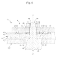
figure 5 est une vue agrandie en coupe axiale suivant le plan 5-5 qui représente schématiquement une portion du module d'entraînement et qui illustre le montage à rotation d'un pignon et d'un rotor du micromoteur autour d'un arbre; - la
figure 6 est une vue en coupe axiale schématique suivant le plan X'X qui illustre l'entraînement du pignon par le rotor au moyen de goupilles; - la
figure 7 est une vue de dessus schématique qui illustre l'entraînement du pignon par le rotor au moyen de goupilles; - la
figure 8 est une vue en coupe axiale schématique suivant le plan X'X qui illustre une variante du montage de l'arbre par rapport au rotor; - la
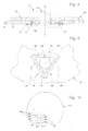
figure 9 est une vue de dessous qui représente schématiquement les structures élastiques de fixation qui sont aménagées dans la plaque pour le serrage et le centrage de l'arbre selon le montage de lafigure 8 ; - la
figure 10 est une vue de dessus qui représente schématiquement un wafer en silicium et qui illustre un exemple d'agencement de plusieurs micromoteurs sur le wafer.
- the
figure 1 is a sectional view which schematically shows a timepiece made in accordance with the teachings of the invention; - the
figure 2 is a perspective view that partially represents the movement of the timepiece of thefigure 1 equipped with a drive module comprising a MEMS micromotor; - the
figure 3 is a top view that schematically represents the training module of thefigure 2 ; - the
figure 4 is an exploded perspective view that represents the drive module of thefigure 2 and the casing enveloping this drive module; - the
figure 5 is an enlarged view in axial section along the plane 5-5 which schematically shows a portion of the drive module and which illustrates the rotational mounting of a pinion and a rotor of the micromotor around a shaft; - the
figure 6 is a schematic axial sectional view along the X'X plane which illustrates the driving of the pinion by the rotor by means of pins; - the
figure 7 is a schematic top view illustrating the driving of the pinion by the rotor by means of pins; - the
figure 8 is a schematic axial sectional view along the X'X plane which illustrates a variant of the mounting of the shaft relative to the rotor; - the
figure 9 is a view from below which schematically represents the elastic fastening structures which are arranged in the plate for clamping and centering the shaft according to the mounting of thefigure 8 ; - the
figure 10 is a top view which schematically shows a silicon wafer and illustrates an example of arrangement of several micromotors on the wafer.
Sur la
La pièce d'horlogerie 10 comporte une boîte de montre 14 fermée par une glace 16, un cadran 18, et des moyens d'affichage analogique constituées ici par des aiguilles 20. Les aiguilles 20 sont prévues pour être entraînées en rotation par le module d'entraînement 13 selon l'invention, via un rouage 22 comportant, par exemple, des moyens de démultiplication. Le module d'entraînement 13 est alimenté en énergie électrique par une pile 24. Le boîtier 12, le module d'entraînement 13, le rouage 22, et la pile 24 sont ici montés sur une platine 26 et forment ensemble le mouvement 27 de la pièce d'horlogerie 10, ce mouvement 27 étant fixé à l'intérieur de la boîte de montre 14. Bien entendu, le mouvement 27 comporte d'autres éléments (non représentés), en particulier un module électronique comportant un circuit intégré, une base de temps comportant un quartz, une plaque à circuits imprimés etc.The
Sur la
Le module d'entraînement 13 est destiné à engrener avec une roue horlogère dite roue d'entrée 28 du rouage 22.The
Les différents éléments du module d'entraînement 13 selon l'invention sont représentés plus en détail sur les
Le module d'entraînement 13 comporte une plaque 30 en matériau cristallin ou amorphe, par exemple du silicium, comprenant une couche inférieure qui constitue un substrat 32, et une couche supérieure 34 dans laquelle est gravée un micromoteur 36 du type MEMS (Micro ElectroMechanical System). Le micromoteur 36 est constitué ici par deux actionneurs 38, 40 entraînant en rotation un rotor 42 gravé dans la couche supérieure 34.The
Chaque actionneur 38, 40 comporte un stylet 44, 46 mobile suivant une direction A1, A2 parallèle au plan de la plaque 30. Chaque stylet 44, 46 est muni à son extrémité libre d'un cliquet 48, 50 prévu pour coopérer avec une denture 52 à dents de scie aménagée sur le bord périphérique extérieur du rotor 42 en vue de l'entraîner en rotation séquentiellement.Each
De préférence, chaque stylet 44, 46 s'étend suivant une direction A1, A2 qui coupe l'actionneur 38, 40 associé en deux parties globalement symétriques. De préférence, un premier actionneur 38 comporte un cliquet de poussée 48 et un second actionneur 40 comporte un cliquet de traction 50.Preferably, each stylet 44, 46 extends in a direction A1, A2 which cuts the
Chaque actionneur 38, 40 est ici du type électrostatique à peignes interdigités et réalisé par gravure dans la plaque 30 en silicium. La plaque 30 est ici du type Silicon On Insulator (SOI) et comprend une couche inférieure 32 épaisse de substrat en silicium, une couche intermédiaire 54 d'oxyde de silicium , et une couche supérieure 34 en silicium d'épaisseur inférieure au substrat 32.Each
La partie fixe de chaque actionneur 38, 40 comporte une plage 56, 58 d'alimentation prévue pour être raccordée électriquement au module électronique, et la partie mobile de chaque actionneur 38, 40 comporte une plage de contact 57, 59 qui place ces parties mobiles à un potentiel déterminé, ici à zéro Volts.The fixed part of each actuator 38, 40 has a
Un micromoteur comportant des actionneurs électrostatiques réalisés dans une plaque en silicium est décrit et représenté, par exemple, dans le document
Un mode de réalisation utilisant une plaque SOI est décrit en référence aux
Selon un mode de réalisation avantageux, chaque actionneur 38, 40 est associé à un cliquet passif 49, 51 dont la zone d'encliquetage est située entre la zone d'engrènement 70 et la zone d'encliquetage du cliquet associé. Ces cliquets passifs 49, 51 sont maintenus élastiquement engrenés avec le rotor 42 de manière à assurer un positionnement angulaire précis, notamment au cours des phases d'entraînement, lorsque les autres cliquets 48, 50 se déplacent.According to an advantageous embodiment, each actuator 38, 40 is associated with a passive pawl 49, 51 whose latching zone is located between the engagement zone 70 and the latching zone of the associated pawl. These passive pawls 49, 51 are held elastically intermeshed with the
Selon le mode de réalisation représenté sur les
Le couple du rotor 42 est transmis à un pignon 62 par un système apparenté à une manivelle. Le pignon 62 situé juste au-dessus du rotor 42, est coaxial à ce dernier et il est guidé par un arbre 64 central. Le pignon 62 est doté de goupilles 66, engagées dans des fenêtres 68 du rotor 42. Des jeux de fonctionnement j_goup, j_rot, j_pi sont ménagés entre les divers éléments du rotor 42 et du pignon 62 comme représentés sur le schéma de la
Le pignon 62 est prévu pour engrener avec la roue d'entrée 28 du rouage 22 dans une zone d'engrènement 70 située à proximité d'un bord périphérique extérieur 72 de la plaque 30.
Selon une caractéristique avantageuse, le rotor 42 est agencé sur la plaque 30 de manière à minimiser la distance D entre la denture 52 du rotor 42 et le bord périphérique extérieur 72 de la plaque 30 correspondant à la zone d'engrènement 70. De plus, le diamètre extérieur du pignon 62 est légèrement supérieur à celui du rotor 42 de manière à être en porte-à-faux par rapport à la plaque 30 dans la zone d'engrènement 70.According to an advantageous characteristic, the
Pour simplifier le schéma de la
Selon un mode de réalisation préféré, la position angulaire de la zone d'encliquetage de chaque cliquet 48, 50 avec le rotor 42 est décalée angulairement par rapport à la zone d'engrènement 70. La zone d'encliquetage de chaque cliquet 48, 50 forme un angle β avec l'axe x'x. α représente l'angle, à un instant donné, entre le rayon passant par la goupille 66 qui est en appui, en prise, contre le bord de sa fenêtre 68, et l'axe x'x (
Ensuite, un choix judicieux de l'ensemble des paramètres {α, β, j_rot, j_pi, j_goup} pour des rayons de pignon 62, de rotor 42 et du cercle de goupilles 66 donnés favorisera le rendement de la transmission de l'énergie mécanique depuis le rotor 42 vers le pignon 62. Ainsi, pour un cas particulier de l'invention ayant β = 45°, si les jeux sont bien ajustés, le rendement pour un système à quatre goupilles avoisine les 85%, ce qui améliore le rendement par rapport à un cas où le rotor 42 et le pignon 62 sont collés l'un à l'autre. En effet, dans ce dernier cas toute la charge se retrouverait sous forme de frottement silicium-silicium latéral au niveau du palier 60, et vertical entre la périphérie du rotor 42 et le substrat 32 à cause du couple de basculement. Or le frottement silicium-silicium est plutôt défavorable, avec des coefficients secs statiques approchant 0,4.Then, a judicious choice of the set of parameters {α, β, j_rot, j_pi, j_goup} for
Cette solution de transmission permet encore de varier le diamètre du pignon 62 afin d'adapter les couples et les vitesses, selon les charges. De plus, si le pignon 62 est assez grand et dépasse du bord périphérique 72 de la plaque 30, l'engrènement par la tranche s'en trouve simplifié, et le module d'entraînement 13 peut être assemblé sur la platine 26 de la pièce d'horlogerie 10 de façon modulaire, c'est-à-dire sans démonter/remonter la roue 28 entraînée.This transmission solution makes it possible to vary the diameter of the
Selon différentes variantes :
le rotor 42 est microfabriqué en place, et sur le même substrat 32 que les actionneurs 38, 40, afin de garantir un appairage au palier 60 et aux cliquets;- une autre variante consiste à fabriquer
un rotor 42 séparément, sur le même wafer ou sur un autre wafer,ce rotor 42 étant ensuite assemblé sur laplaque 30 ou stator. Ceci permet une réduction du jeu radial si désiré dans le cas où le rotor est guidé par le palier 60; - une famille de variantes est constituée par des rotors 42 et/ou des pignons 62 microfabriqués par d'autres procédés que l'usinage DRIE (découpe laser, EDM, LIGA, microinjection, etc.) puis assemblés sur la
plaque 30 au stator; - une autre famille de variantes est constituée de goupilles 66 formées par un deuxième niveau photolithographique dans le pignon 62 et/ou dans le
rotor 42.
- the
rotor 42 is microfabricated in place, and on thesame substrate 32 as theactuators bearing 60 and the pawls; - another variant is to manufacture a
rotor 42 separately, on the same wafer or on another wafer, thisrotor 42 is then assembled on theplate 30 or stator. This allows a reduction of the radial clearance if desired in the case where the rotor is guided by thebearing 60; - a family of variants is constituted by
rotors 42 and / or gears 62 microfabricated by other methods than the DRIE machining (laser cutting, EDM, LIGA, microinjection, etc.) and then assembled on theplate 30 to the stator; - another family of variants consists of
pins 66 formed by a second photolithographic level in thepinion 62 and / or in therotor 42.
Le module d'entraînement 13 selon l'invention permet une modularité accrue pour l'adaptation à la charge, en permettant l'utilisation de pignons 62 de divers diamètres, sans modifier le reste du module 13. On obtient aussi une modularité accrue pour l'assemblage car l'interface mécanique pour la liaison au rouage 22 horloger est déjà existante grâce à la présence du pignon 62, intégré au module d'entraînement 13 et lié en rotation au micromoteur 36.The
Le pignon 62 peut être réalisé en métal tel que du laiton, avec des goupilles 66 rapportées réalisées aussi en métal. Le pignon 62 peut aussi être réalisé d'une seule pièce avec les goupilles 66 par moulage en matériau plastique. Une réalisation du pignon 62 en matériau plastique avec des goupilles 66 métalliques surmoulées est aussi envisageable.The
Selon le mode de réalisation représenté notamment sur les
L'arbre 64 comporte un tronçon d'extrémité inférieure 78 qui délimite avec un tronçon intermédiaire inférieur 80 une première surface d'épaulement 82 orientée vers le haut et venant en butée axiale contre la face inférieure de la plaque 30. Le tronçon intermédiaire inférieur 80 a un diamètre sensiblement égal au diamètre du premier trou 74 et il s'étend dans ce trou 74. L'arbre comporte un tronçon intermédiaire supérieur 84 de diamètre légèrement inférieur au tronçon intermédiaire inférieur 80 adjacent et qui s'étend dans l'alésage 86 du pignon 62 pour le guider en rotation. Le tronçon intermédiaire supérieur 84 délimite avec le tronçon d'extrémité supérieure 88 une seconde surface d'épaulement 90 contre laquelle est maintenue en appui axial une bague de fixation 92 qui est chassée sur le tronçon d'extrémité supérieure 88.The
Comme le guidage en rotation du rotor 42 est réalisé par le palier 60, qui est réalisé par un procédé photolithographique de gravure de la même manière que premier trou 74 qui détermine le centrage de l'arbre 64 par rapport au palier 60, on obtient un très bon centrage de l'arbre 64, du pignon 62, du palier 60 et du rotor 42.Since the rotation guide of the
De plus, la face inférieure du pignon 62 comporte, en vis-à-vis du palier 60, un bossage 94 qui empêche le pignon 62 de venir en appui axial contre le rotor 42, notamment en cas de basculement, ce qui évite une détérioration du rotor 42.In addition, the lower face of the
Sur les
Les structures élastiques de fixation 96 sont constituées ici par des lames flexibles 98 lithographiées dans la face arrière de la plaque 30. La lithographie de la face avant, pour la couche supérieure 34 comportant les cliquets 48, 50 et le rotor 42, étant également alignée et centrée très précisément par rapport à la lithographie de la face arrière (erreur inférieure à 1 micron), il en résulte un guidage et un centrage plus précis qu'avec un axe réalisé d'une seul pièce avec la plaque 30, puisque le jeu radial peut être également réduit à un micron.The
Grâce à cet alignement et ce centrage précis, il est possible de supprimer le palier 60 de sorte que le rotor 42 est alors guidé en rotation directement par l'arbre 64. Ainsi l'arbre 64 peut guider en rotation à la fois le rotor 42 et le pignon 62. Comme l'arbre 64 est réalisé par décolletage, ce qui permet d'obtenir des tolérances de fabrication très restreintes, on obtient un assemblage très précis, ce qui assure notamment un fonctionnement fiable des actionneurs 38, 40. Le rotor 42 est alors guidé par la paroi axiale externe de l'arbre 64.With this precise alignment and centering, it is possible to remove the
L'arbre 64 peut être finalement fixé dans la plaque 30 par un moyen de fixation complémentaire, par exemple par soudage au substrat 32 au moyen d'un cordon de soudure 99 qui est représenté sur la
Les problèmes de frottement contre l'arbre 64 peuvent être résolus par déposition d'une couche mince solide sur la paroi axiale externe de l'arbre 64 permettant de diminuer le frottement entre les pièces.The problems of friction against the
Les structures élastiques de fixation 96 peuvent être choisies notamment parmi les exemples décrits et représentés dans le document
Avantageusement, en considérant notamment la
La plaque 30 comporte une portion centrale 100 qui porte le rotor 42 et deux portions latérales 102, 104. Le contour extérieur de la plaque 30 correspond globalement à l'intersection de deux rectangles, qui sont orthogonaux entre eux et qui forment les deux portions latérales 102, 104, avec un rectangle transversal, qui forme la portion centrale 100, le rectangle transversal décrivant un angle de quarante-cinq degrés par rapport à chacun des deux autres rectangles. La majeure partie de la surface de chaque portion latérale 102, 104 est occupée par un actionneur 38, 40 alors que la majeure partie de la surface de la portion centrale 100 est occupée par le rotor 42. La zone d'engrènement 70 est agencée à proximité d'un des bords périphériques 72 de la portion centrale 100.The
De préférence, les plages 56, 57, 58, 59 sont agencées sur la portion centrale 100, du côté opposé à la zone d'engrènement 70 par rapport à l'axe z'z du rotor 42.Preferably, the
On note que la forme en "V" du module d'entraînement 13 présente l'avantage de permettre une optimisation du rendement du micromoteur 36 par rapport à la surface de la plaque 30 utilisée, et une optimisation de la surface de matériau cristallin ou amorphe utilisée pour réaliser les micromoteurs 36 et les modules d'entraînement 13. Ainsi, lorsque la plaque 30 est réalisée à partir d'un wafer 101 en silicium, comme schématisé sur la
De préférence, l'angle décrit par les deux actionneurs 38, 40 est compris entre quatre-vingt-dix et cent quarante degrés. Plus l'angle est important, plus l'imbrication des plaques 30 sur le wafer 101 est optimisée, mais les angles importants nécessitent de déporter les stylets 44, 46 des actionneurs 38, 40 par rapport à leurs axes de symétrie A1, A2 respectifs, ce qui pénalise l'efficacité mécanique des actionneurs 38, 40.Preferably, the angle described by the two
Selon le mode de réalisation représenté sur les figures, le boîtier 12 qui contient le module d'entraînement 13 comporte une platine inférieure 106 prévue pour être fixée sur un élément de la pièce d'horlogerie 10, ici sur la platine 26 du mouvement, et la plaque 30 du module d'entraînement 13 est montée sur la platine inférieure 106. Le boîtier 12 comporte un capot 108 de protection qui recouvre le module d'entraînement 13, qui est fixé sur la platine inférieure 106, ici au moyen d'une vis 109, et qui retient le module d'entraînement 13 contre la platine inférieure 106.According to the embodiment shown in the figures, the
La face supérieure de la platine inférieure 106 comporte ici une creusure ou logement 110 dans lequel la plaque 30 du module d'entraînement 13 est reçue de manière sensiblement complémentaire.The upper face of the
Le capot 108 comporte une échancrure 112 ouverte dans un de ses bords périphériques extérieurs et le pignon 62 est logé dans cette échancrure 112 après montage du capot 108 sur la platine inférieure 106.The
Avantageusement, un circuit imprimé 114 est intercalé entre la platine inférieure 106 et le capot 108 pour permettre le raccordement électrique du micromoteur 36, par ses plages 56, 57, 58, 59, au module électronique de la pièce d'horlogerie 10.Advantageously, a printed
Selon une variante de réalisation (non représentée), le module d'entraînement 13 peut être monté directement sur la platine 26, ce qui permet de supprimer le boîtier 12, notamment pour minimiser le nombre de composants, pour faciliter l'assemblage du mouvement 27, et pour minimiser l'encombrement des moyens d'entraînement. Un élément de protection peut être prévu sur le module d'entraînement 13 pour protéger ses composants.According to an alternative embodiment (not shown), the
Claims (11)
Priority Applications (9)
| Application Number | Priority Date | Filing Date | Title |
|---|---|---|---|
| EP06123973A EP1921520B1 (en) | 2006-11-13 | 2006-11-13 | Drive module incorporating an MEMS micromotor, manufacturing process for this module, and time piece equipped with this module |
| AT06123973T ATE422068T1 (en) | 2006-11-13 | 2006-11-13 | DRIVE MODULE COMPRISING A MEMS MICROMOTOR, METHOD FOR PRODUCING THIS MODULE AND CLOCK EQUIPPED WITH THIS MODULE |
| DE602006005058T DE602006005058D1 (en) | 2006-11-13 | 2006-11-13 | A drive module comprising a MEMS micromotor, method of making this module, and clock equipped with this module |
| SG200717593-8A SG143157A1 (en) | 2006-11-13 | 2007-11-09 | Drive module comprising an mems micromotor, process for the production of this module and timepiece fitted with this module |
| KR1020070114709A KR101401200B1 (en) | 2006-11-13 | 2007-11-12 | Drive module comprising an mems micromotor, process for the production of this module and timepiece fitted with this module |
| JP2007294762A JP4971108B2 (en) | 2006-11-13 | 2007-11-13 | Drive module including a MEMS micromotor, process for the manufacture of this module, and timer with this module |
| US11/939,166 US7447119B2 (en) | 2006-11-13 | 2007-11-13 | Drive module comprising an MEMS micromotor, process for the production of this module and timepiece fitted with this module |
| CN2007101869230A CN101183837B (en) | 2006-11-13 | 2007-11-13 | Drive module of an mems micromotor, manufacturing process for this module, and time piece equipped with this module |
| HK08112363.6A HK1120935A1 (en) | 2006-11-13 | 2008-11-11 | Drive module comprising mems micromotor, process for the production of this module and timepiece fitted with this module |
Applications Claiming Priority (1)
| Application Number | Priority Date | Filing Date | Title |
|---|---|---|---|
| EP06123973A EP1921520B1 (en) | 2006-11-13 | 2006-11-13 | Drive module incorporating an MEMS micromotor, manufacturing process for this module, and time piece equipped with this module |
Publications (2)
| Publication Number | Publication Date |
|---|---|
| EP1921520A1 true EP1921520A1 (en) | 2008-05-14 |
| EP1921520B1 EP1921520B1 (en) | 2009-01-28 |
Family
ID=37845237
Family Applications (1)
| Application Number | Title | Priority Date | Filing Date |
|---|---|---|---|
| EP06123973A Active EP1921520B1 (en) | 2006-11-13 | 2006-11-13 | Drive module incorporating an MEMS micromotor, manufacturing process for this module, and time piece equipped with this module |
Country Status (9)
| Country | Link |
|---|---|
| US (1) | US7447119B2 (en) |
| EP (1) | EP1921520B1 (en) |
| JP (1) | JP4971108B2 (en) |
| KR (1) | KR101401200B1 (en) |
| CN (1) | CN101183837B (en) |
| AT (1) | ATE422068T1 (en) |
| DE (1) | DE602006005058D1 (en) |
| HK (1) | HK1120935A1 (en) |
| SG (1) | SG143157A1 (en) |
Cited By (1)
| Publication number | Priority date | Publication date | Assignee | Title |
|---|---|---|---|---|
| EP2177960A1 (en) | 2008-10-16 | 2010-04-21 | ETA SA Manufacture Horlogère Suisse | Blocking mechanism for a clock drive module |
Families Citing this family (4)
| Publication number | Priority date | Publication date | Assignee | Title |
|---|---|---|---|---|
| DE602006019612D1 (en) * | 2006-11-13 | 2011-02-24 | Eta Sa Mft Horlogere Suisse | MEMS micromotor and clock equipped with this micromotor |
| EP2189854A1 (en) * | 2008-11-21 | 2010-05-26 | Nivarox-FAR S.A. | Method for manufacturing a micromechanical part |
| CH703475B1 (en) * | 2010-07-30 | 2015-06-30 | Swatch Group Res & Dev Ltd | A method of making a noncontact transmission in a timepiece movement. |
| EP2735922A1 (en) * | 2012-11-23 | 2014-05-28 | ETA SA Manufacture Horlogère Suisse | Drive mechanism for the hands of an electro-mechanical watch, provided with a locking device |
Citations (4)
| Publication number | Priority date | Publication date | Assignee | Title |
|---|---|---|---|---|
| FR2101203A1 (en) * | 1970-08-03 | 1972-03-31 | Bulova Watch Co Inc | |
| US5959376A (en) * | 1998-09-10 | 1999-09-28 | Sandia Corporation | Microelectromechanical reciprocating-tooth indexing apparatus |
| US6211599B1 (en) * | 1999-08-03 | 2001-04-03 | Sandia Corporation | Microelectromechanical ratcheting apparatus |
| FR2874907A1 (en) * | 2004-09-03 | 2006-03-10 | Silmach Soc Par Actions Simpli | TRAINING DEVICE, IN PARTICULAR FOR WATCHMAKING MECHANISM |
Family Cites Families (22)
| Publication number | Priority date | Publication date | Assignee | Title |
|---|---|---|---|---|
| JPS4993280U (en) * | 1972-12-06 | 1974-08-13 | ||
| JPS54143271A (en) * | 1978-04-28 | 1979-11-08 | Citizen Watch Co Ltd | Assembling structure of rotor for converter |
| JPS5415781A (en) * | 1978-07-20 | 1979-02-05 | Matsushita Electric Works Ltd | Crystal watch |
| JP3019324B2 (en) * | 1988-06-17 | 2000-03-13 | セイコーエプソン株式会社 | Analog electronic clock IC and analog electronic clock |
| JPH078149B2 (en) | 1989-06-16 | 1995-01-30 | 松下電器産業株式会社 | Driving force transmission device for electrostatic micromotor |
| JP3060639B2 (en) | 1991-09-05 | 2000-07-10 | 日本電気株式会社 | Manufacturing method of micro movable machine |
| US5631514A (en) * | 1994-06-09 | 1997-05-20 | The United States Of America As Represented By The United States Department Of Energy | Microfabricated microengine for use as a mechanical drive and power source in the microdomain and fabrication process |
| JP2697763B2 (en) | 1994-09-28 | 1998-01-14 | セイコークロック株式会社 | Viscous coupling gear device |
| US6069419A (en) * | 1998-06-16 | 2000-05-30 | Tabib-Azar; Massood | Micro-actuator assembly |
| US6329737B1 (en) * | 1998-12-15 | 2001-12-11 | Iolon, Inc. | Rotary electrostatic microactuator |
| CN100367649C (en) | 1998-12-21 | 2008-02-06 | 精工爱普生株式会社 | Piezoelectric actuator and timepiece |
| US6137206A (en) * | 1999-03-23 | 2000-10-24 | Cronos Integrated Microsystems, Inc. | Microelectromechanical rotary structures |
| US6402969B1 (en) | 2000-08-15 | 2002-06-11 | Sandia Corporation | Surface—micromachined rotatable member having a low-contact-area hub |
| US6402939B1 (en) * | 2000-09-28 | 2002-06-11 | Sulphco, Inc. | Oxidative desulfurization of fossil fuels with ultrasound |
| JP2004072993A (en) | 2002-06-14 | 2004-03-04 | Seiko Epson Corp | Piezoelectric actuator, power transmission with the same, liquid discharge device, and clock |
| SG112865A1 (en) * | 2002-12-10 | 2005-07-28 | Sony Corp | Mems based motor |
| CH695395A5 (en) | 2003-02-06 | 2006-04-28 | Eta Sa Mft Horlogere Suisse | Hairspring for balance wheel-hairspring resonator of watch, has self-locking washer with triangular contour in its central opening to subject hairspring to pin of balance wheel, where contour has openings formed through washer |
| FR2852111B1 (en) * | 2003-03-05 | 2005-06-24 | Univ Franche Comte | CLOCK DEVICE USING MEMS TECHNOLOGY |
| JP2004279251A (en) | 2003-03-17 | 2004-10-07 | Citizen Watch Co Ltd | Pocket trick-action type clock |
| US7238429B2 (en) | 2003-09-23 | 2007-07-03 | Iowa State University Research Foundation, Inc. | Ultra-hard low friction coating based on A1MgB14 for reduced wear of MEMS and other tribological components and system |
| FR2883277B1 (en) | 2005-03-18 | 2007-05-11 | Silmach Soc Par Actions Simpli | METHOD AND DEVICE FOR MOVING A DRIVE MEMBER USING AN ETCHED ACTUATOR MEMBER IN A SEMICONDUCTOR MATERIAL |
| US7411322B2 (en) * | 2005-12-06 | 2008-08-12 | Lucent Technologies Inc. | Micromachined reluctance motor |
-
2006
- 2006-11-13 EP EP06123973A patent/EP1921520B1/en active Active
- 2006-11-13 AT AT06123973T patent/ATE422068T1/en active
- 2006-11-13 DE DE602006005058T patent/DE602006005058D1/en active Active
-
2007
- 2007-11-09 SG SG200717593-8A patent/SG143157A1/en unknown
- 2007-11-12 KR KR1020070114709A patent/KR101401200B1/en active IP Right Grant
- 2007-11-13 JP JP2007294762A patent/JP4971108B2/en active Active
- 2007-11-13 US US11/939,166 patent/US7447119B2/en active Active
- 2007-11-13 CN CN2007101869230A patent/CN101183837B/en active Active
-
2008
- 2008-11-11 HK HK08112363.6A patent/HK1120935A1/en unknown
Patent Citations (4)
| Publication number | Priority date | Publication date | Assignee | Title |
|---|---|---|---|---|
| FR2101203A1 (en) * | 1970-08-03 | 1972-03-31 | Bulova Watch Co Inc | |
| US5959376A (en) * | 1998-09-10 | 1999-09-28 | Sandia Corporation | Microelectromechanical reciprocating-tooth indexing apparatus |
| US6211599B1 (en) * | 1999-08-03 | 2001-04-03 | Sandia Corporation | Microelectromechanical ratcheting apparatus |
| FR2874907A1 (en) * | 2004-09-03 | 2006-03-10 | Silmach Soc Par Actions Simpli | TRAINING DEVICE, IN PARTICULAR FOR WATCHMAKING MECHANISM |
Cited By (3)
| Publication number | Priority date | Publication date | Assignee | Title |
|---|---|---|---|---|
| EP2177960A1 (en) | 2008-10-16 | 2010-04-21 | ETA SA Manufacture Horlogère Suisse | Blocking mechanism for a clock drive module |
| CN101727060B (en) * | 2008-10-16 | 2012-06-20 | 伊塔瑞士钟表制造股份有限公司 | Locking mechanism for timepiece drive module |
| US8259538B2 (en) | 2008-10-16 | 2012-09-04 | Eta Sa Manufacture Horlogère Suisse | Locking mechanism for timepiece drive module |
Also Published As
| Publication number | Publication date |
|---|---|
| JP2008122390A (en) | 2008-05-29 |
| ATE422068T1 (en) | 2009-02-15 |
| EP1921520B1 (en) | 2009-01-28 |
| SG143157A1 (en) | 2008-06-27 |
| CN101183837A (en) | 2008-05-21 |
| JP4971108B2 (en) | 2012-07-11 |
| CN101183837B (en) | 2011-04-06 |
| HK1120935A1 (en) | 2009-04-09 |
| DE602006005058D1 (en) | 2009-03-19 |
| US20080111445A1 (en) | 2008-05-15 |
| US7447119B2 (en) | 2008-11-04 |
| KR20080043236A (en) | 2008-05-16 |
| KR101401200B1 (en) | 2014-05-28 |
Similar Documents
| Publication | Publication Date | Title |
|---|---|---|
| EP1921521B1 (en) | MEMS micromotor and timepiece equipped with this micromotor | |
| EP1921522B1 (en) | Arrangement for mechanical interface of an MEMS micromotor with a clock wheel and time piece incorporating this arrangement | |
| EP1797483B9 (en) | Drive device, particularly for a clockwork mechanism | |
| EP1921517B1 (en) | Assembly component comprising fork-shaped elastic structures and timepiece incorporating this component | |
| EP1921520B1 (en) | Drive module incorporating an MEMS micromotor, manufacturing process for this module, and time piece equipped with this module | |
| EP1599766B1 (en) | Method of producing a mems device | |
| EP2326995B1 (en) | Gear system for a timepiece | |
| EP1921518A1 (en) | Assembly component comprising overlaid blade-shaped elastic structures and timepiece equipped with this component | |
| CH709508B1 (en) | Watch movement with a drive mechanism of an analogue indicator with periodic or intermittent movement. | |
| EP3223084B1 (en) | Display mechanism for a watch | |
| EP1780612A1 (en) | Vorrichtung zur analogen Anzeige, die eine Planetengetriebe aufweist | |
| EP1864374B1 (en) | Method and device for moving an element to be driven using an actuating element formed by etching in a semiconductor material | |
| CH685660B5 (en) | Timepiece provided with drive means forms by a piezoelectric motor. | |
| EP1760557B1 (en) | Timepiece comprising a semi-conductive dial | |
| EP1870784B1 (en) | Micro-mechanical wheel with impact-controlled rotation | |
| EP1896305A1 (en) | Drive mechanism especially for a window wiping device with an elliptical wiping motion | |
| EP3889688B1 (en) | Motor member for a timepiece | |
| EP2138912B1 (en) | Horological hairspring with concentric development | |
| EP3786720A1 (en) | Clock component for receiving an organ by insertion | |
| CH714767B1 (en) | Device for collecting mechanical energy in particular for a timepiece, a watch movement and a timepiece comprising such a device. | |
| CH712346A2 (en) | Display mechanism for a watch. |
Legal Events
| Date | Code | Title | Description |
|---|---|---|---|
| PUAI | Public reference made under article 153(3) epc to a published international application that has entered the european phase |
Free format text: ORIGINAL CODE: 0009012 |
|
| 17P | Request for examination filed |
Effective date: 20070523 |
|
| AK | Designated contracting states |
Kind code of ref document: A1 Designated state(s): AT BE BG CH CY CZ DE DK EE ES FI FR GB GR HU IE IS IT LI LT LU LV MC NL PL PT RO SE SI SK TR |
|
| AX | Request for extension of the european patent |
Extension state: AL BA HR MK RS |
|
| GRAP | Despatch of communication of intention to grant a patent |
Free format text: ORIGINAL CODE: EPIDOSNIGR1 |
|
| GRAS | Grant fee paid |
Free format text: ORIGINAL CODE: EPIDOSNIGR3 |
|
| GRAA | (expected) grant |
Free format text: ORIGINAL CODE: 0009210 |
|
| AKX | Designation fees paid |
Designated state(s): AT BE BG CH CY CZ DE DK EE ES FI FR GB GR HU IE IS IT LI LT LU LV MC NL PL PT RO SE SI SK TR |
|
| AK | Designated contracting states |
Kind code of ref document: B1 Designated state(s): AT BE BG CH CY CZ DE DK EE ES FI FR GB GR HU IE IS IT LI LT LU LV MC NL PL PT RO SE SI SK TR |
|
| REG | Reference to a national code |
Ref country code: GB Ref legal event code: FG4D Free format text: NOT ENGLISH |
|
| REG | Reference to a national code |
Ref country code: CH Ref legal event code: EP |
|
| REG | Reference to a national code |
Ref country code: IE Ref legal event code: FG4D Free format text: LANGUAGE OF EP DOCUMENT: FRENCH |
|
| REF | Corresponds to: |
Ref document number: 602006005058 Country of ref document: DE Date of ref document: 20090319 Kind code of ref document: P |
|
| REG | Reference to a national code |
Ref country code: CH Ref legal event code: NV Representative=s name: ICB INGENIEURS CONSEILS EN BREVETS SA |
|
| NLV1 | Nl: lapsed or annulled due to failure to fulfill the requirements of art. 29p and 29m of the patents act | ||
| PG25 | Lapsed in a contracting state [announced via postgrant information from national office to epo] |
Ref country code: SI Free format text: LAPSE BECAUSE OF FAILURE TO SUBMIT A TRANSLATION OF THE DESCRIPTION OR TO PAY THE FEE WITHIN THE PRESCRIBED TIME-LIMIT Effective date: 20090128 Ref country code: NL Free format text: LAPSE BECAUSE OF FAILURE TO SUBMIT A TRANSLATION OF THE DESCRIPTION OR TO PAY THE FEE WITHIN THE PRESCRIBED TIME-LIMIT Effective date: 20090128 Ref country code: ES Free format text: LAPSE BECAUSE OF FAILURE TO SUBMIT A TRANSLATION OF THE DESCRIPTION OR TO PAY THE FEE WITHIN THE PRESCRIBED TIME-LIMIT Effective date: 20090509 Ref country code: LT Free format text: LAPSE BECAUSE OF FAILURE TO SUBMIT A TRANSLATION OF THE DESCRIPTION OR TO PAY THE FEE WITHIN THE PRESCRIBED TIME-LIMIT Effective date: 20090128 |
|
| REG | Reference to a national code |
Ref country code: IE Ref legal event code: FD4D |
|
| PG25 | Lapsed in a contracting state [announced via postgrant information from national office to epo] |
Ref country code: PT Free format text: LAPSE BECAUSE OF FAILURE TO SUBMIT A TRANSLATION OF THE DESCRIPTION OR TO PAY THE FEE WITHIN THE PRESCRIBED TIME-LIMIT Effective date: 20090629 Ref country code: IS Free format text: LAPSE BECAUSE OF FAILURE TO SUBMIT A TRANSLATION OF THE DESCRIPTION OR TO PAY THE FEE WITHIN THE PRESCRIBED TIME-LIMIT Effective date: 20090528 Ref country code: SE Free format text: LAPSE BECAUSE OF FAILURE TO SUBMIT A TRANSLATION OF THE DESCRIPTION OR TO PAY THE FEE WITHIN THE PRESCRIBED TIME-LIMIT Effective date: 20090428 Ref country code: LV Free format text: LAPSE BECAUSE OF FAILURE TO SUBMIT A TRANSLATION OF THE DESCRIPTION OR TO PAY THE FEE WITHIN THE PRESCRIBED TIME-LIMIT Effective date: 20090128 Ref country code: PL Free format text: LAPSE BECAUSE OF FAILURE TO SUBMIT A TRANSLATION OF THE DESCRIPTION OR TO PAY THE FEE WITHIN THE PRESCRIBED TIME-LIMIT Effective date: 20090128 |
|
| PG25 | Lapsed in a contracting state [announced via postgrant information from national office to epo] |
Ref country code: DK Free format text: LAPSE BECAUSE OF FAILURE TO SUBMIT A TRANSLATION OF THE DESCRIPTION OR TO PAY THE FEE WITHIN THE PRESCRIBED TIME-LIMIT Effective date: 20090128 Ref country code: CZ Free format text: LAPSE BECAUSE OF FAILURE TO SUBMIT A TRANSLATION OF THE DESCRIPTION OR TO PAY THE FEE WITHIN THE PRESCRIBED TIME-LIMIT Effective date: 20090128 Ref country code: EE Free format text: LAPSE BECAUSE OF FAILURE TO SUBMIT A TRANSLATION OF THE DESCRIPTION OR TO PAY THE FEE WITHIN THE PRESCRIBED TIME-LIMIT Effective date: 20090128 Ref country code: IE Free format text: LAPSE BECAUSE OF FAILURE TO SUBMIT A TRANSLATION OF THE DESCRIPTION OR TO PAY THE FEE WITHIN THE PRESCRIBED TIME-LIMIT Effective date: 20090128 |
|
| PG25 | Lapsed in a contracting state [announced via postgrant information from national office to epo] |
Ref country code: RO Free format text: LAPSE BECAUSE OF FAILURE TO SUBMIT A TRANSLATION OF THE DESCRIPTION OR TO PAY THE FEE WITHIN THE PRESCRIBED TIME-LIMIT Effective date: 20090128 Ref country code: SK Free format text: LAPSE BECAUSE OF FAILURE TO SUBMIT A TRANSLATION OF THE DESCRIPTION OR TO PAY THE FEE WITHIN THE PRESCRIBED TIME-LIMIT Effective date: 20090128 |
|
| PLBE | No opposition filed within time limit |
Free format text: ORIGINAL CODE: 0009261 |
|
| STAA | Information on the status of an ep patent application or granted ep patent |
Free format text: STATUS: NO OPPOSITION FILED WITHIN TIME LIMIT |
|
| 26N | No opposition filed |
Effective date: 20091029 |
|
| PG25 | Lapsed in a contracting state [announced via postgrant information from national office to epo] |
Ref country code: BG Free format text: LAPSE BECAUSE OF FAILURE TO SUBMIT A TRANSLATION OF THE DESCRIPTION OR TO PAY THE FEE WITHIN THE PRESCRIBED TIME-LIMIT Effective date: 20090428 |
|
| PGFP | Annual fee paid to national office [announced via postgrant information from national office to epo] |
Ref country code: AT Payment date: 20091026 Year of fee payment: 4 |
|
| BERE | Be: lapsed |
Owner name: ETA SA MANUFACTURE HORLOGERE SUISSE Effective date: 20091130 |
|
| PG25 | Lapsed in a contracting state [announced via postgrant information from national office to epo] |
Ref country code: MC Free format text: LAPSE BECAUSE OF NON-PAYMENT OF DUE FEES Effective date: 20091130 |
|
| PG25 | Lapsed in a contracting state [announced via postgrant information from national office to epo] |
Ref country code: GR Free format text: LAPSE BECAUSE OF FAILURE TO SUBMIT A TRANSLATION OF THE DESCRIPTION OR TO PAY THE FEE WITHIN THE PRESCRIBED TIME-LIMIT Effective date: 20090429 Ref country code: BE Free format text: LAPSE BECAUSE OF NON-PAYMENT OF DUE FEES Effective date: 20091130 |
|
| PG25 | Lapsed in a contracting state [announced via postgrant information from national office to epo] |
Ref country code: IT Free format text: LAPSE BECAUSE OF FAILURE TO SUBMIT A TRANSLATION OF THE DESCRIPTION OR TO PAY THE FEE WITHIN THE PRESCRIBED TIME-LIMIT Effective date: 20090128 |
|
| PG25 | Lapsed in a contracting state [announced via postgrant information from national office to epo] |
Ref country code: LU Free format text: LAPSE BECAUSE OF NON-PAYMENT OF DUE FEES Effective date: 20091113 |
|
| PG25 | Lapsed in a contracting state [announced via postgrant information from national office to epo] |
Ref country code: HU Free format text: LAPSE BECAUSE OF FAILURE TO SUBMIT A TRANSLATION OF THE DESCRIPTION OR TO PAY THE FEE WITHIN THE PRESCRIBED TIME-LIMIT Effective date: 20090729 |
|
| PG25 | Lapsed in a contracting state [announced via postgrant information from national office to epo] |
Ref country code: TR Free format text: LAPSE BECAUSE OF FAILURE TO SUBMIT A TRANSLATION OF THE DESCRIPTION OR TO PAY THE FEE WITHIN THE PRESCRIBED TIME-LIMIT Effective date: 20090128 |
|
| PG25 | Lapsed in a contracting state [announced via postgrant information from national office to epo] |
Ref country code: CY Free format text: LAPSE BECAUSE OF FAILURE TO SUBMIT A TRANSLATION OF THE DESCRIPTION OR TO PAY THE FEE WITHIN THE PRESCRIBED TIME-LIMIT Effective date: 20090128 |
|
| REG | Reference to a national code |
Ref country code: AT Ref legal event code: MM01 Ref document number: 422068 Country of ref document: AT Kind code of ref document: T Effective date: 20111113 |
|
| PG25 | Lapsed in a contracting state [announced via postgrant information from national office to epo] |
Ref country code: AT Free format text: LAPSE BECAUSE OF NON-PAYMENT OF DUE FEES Effective date: 20111113 |
|
| PGFP | Annual fee paid to national office [announced via postgrant information from national office to epo] |
Ref country code: GB Payment date: 20141024 Year of fee payment: 9 Ref country code: FI Payment date: 20141023 Year of fee payment: 9 |
|
| REG | Reference to a national code |
Ref country code: FR Ref legal event code: PLFP Year of fee payment: 10 |
|
| GBPC | Gb: european patent ceased through non-payment of renewal fee |
Effective date: 20151113 |
|
| REG | Reference to a national code |
Ref country code: FR Ref legal event code: PLFP Year of fee payment: 11 |
|
| PG25 | Lapsed in a contracting state [announced via postgrant information from national office to epo] |
Ref country code: GB Free format text: LAPSE BECAUSE OF NON-PAYMENT OF DUE FEES Effective date: 20151113 |
|
| PG25 | Lapsed in a contracting state [announced via postgrant information from national office to epo] |
Ref country code: FI Free format text: LAPSE BECAUSE OF NON-PAYMENT OF DUE FEES Effective date: 20151113 |
|
| REG | Reference to a national code |
Ref country code: FR Ref legal event code: PLFP Year of fee payment: 12 |
|
| REG | Reference to a national code |
Ref country code: FR Ref legal event code: PLFP Year of fee payment: 13 |
|
| P01 | Opt-out of the competence of the unified patent court (upc) registered |
Effective date: 20230701 |
|
| PGFP | Annual fee paid to national office [announced via postgrant information from national office to epo] |
Ref country code: FR Payment date: 20231019 Year of fee payment: 18 Ref country code: DE Payment date: 20231019 Year of fee payment: 18 Ref country code: CH Payment date: 20231201 Year of fee payment: 18 |