EP1925455A2 - Guide for Printer Solid Ink Transport and Method - Google Patents
Guide for Printer Solid Ink Transport and Method Download PDFInfo
- Publication number
- EP1925455A2 EP1925455A2 EP07121105A EP07121105A EP1925455A2 EP 1925455 A2 EP1925455 A2 EP 1925455A2 EP 07121105 A EP07121105 A EP 07121105A EP 07121105 A EP07121105 A EP 07121105A EP 1925455 A2 EP1925455 A2 EP 1925455A2
- Authority
- EP
- European Patent Office
- Prior art keywords
- solid ink
- stick
- delivery system
- chute
- printer
- Prior art date
- Legal status (The legal status is an assumption and is not a legal conclusion. Google has not performed a legal analysis and makes no representation as to the accuracy of the status listed.)
- Granted
Links
Images


Classifications
-
- B—PERFORMING OPERATIONS; TRANSPORTING
- B41—PRINTING; LINING MACHINES; TYPEWRITERS; STAMPS
- B41J—TYPEWRITERS; SELECTIVE PRINTING MECHANISMS, i.e. MECHANISMS PRINTING OTHERWISE THAN FROM A FORME; CORRECTION OF TYPOGRAPHICAL ERRORS
- B41J2/00—Typewriters or selective printing mechanisms characterised by the printing or marking process for which they are designed
- B41J2/005—Typewriters or selective printing mechanisms characterised by the printing or marking process for which they are designed characterised by bringing liquid or particles selectively into contact with a printing material
- B41J2/01—Ink jet
- B41J2/17—Ink jet characterised by ink handling
- B41J2/175—Ink supply systems ; Circuit parts therefor
- B41J2/17593—Supplying ink in a solid state
-
- B—PERFORMING OPERATIONS; TRANSPORTING
- B41—PRINTING; LINING MACHINES; TYPEWRITERS; STAMPS
- B41J—TYPEWRITERS; SELECTIVE PRINTING MECHANISMS, i.e. MECHANISMS PRINTING OTHERWISE THAN FROM A FORME; CORRECTION OF TYPOGRAPHICAL ERRORS
- B41J29/00—Details of, or accessories for, typewriters or selective printing mechanisms not otherwise provided for
- B41J29/02—Framework
Definitions
- the guide described herein generally relates to high speed printers which have one or more printheads that receive molten ink heated from solid ink sticks or pellets. More specifically, the guide relates to improving the ink transport system design and functionality.
- Solid ink printers encompass various imaging devices, including printers and multi-function platforms and offer many advantages over many other types of high speed or high output document reproduction technologies such as laser and aqueous inkjet approaches. These often include higher document throughput (i.e., the number of documents reproduced over a unit of time), fewer mechanical components needed in the actual image transfer process, fewer consumables to replace, sharper images, as well as being more environmentally friendly (far less packaging waste).
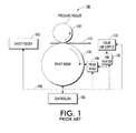
- FIG. 1 A schematic diagram for a typical solid ink imaging device is illustrated in FIG. 1.
- the solid ink imaging device hereafter simply referred to as a printer 100 has an ink loader 110 which receives and stages solid ink sticks which remain in solid form at room temperatures.
- the ink stock can be refilled by a user by simply adding more ink as needed to the ink loader 110.
- Separate loader channels are used for the different colors. For, example, only black solid ink is needed for monochrome printing, while solid ink colors of black, cyan, yellow and magenta are typically needed for color printing. Each color is loaded and fed in independent channels of the ink loader.
- An ink melt unit 120 melts the ink by raising the temperature of the ink sufficiently above its melting point. During a melting phase of operation, the leading end of an ink stick contacts a melt plate or heated surface of the melt unit and the ink is melted in that region. The liquefied ink is supplied to a single or group of print heads 130 by gravity, pump action, or both.
- a rotating print drum 140 receives ink droplets representing the image pixels to be transferred to paper or other media 170 from a sheet feeder 160.
- a pressure roller 150 presses the media 170 against the print drum 140, whereby the ink is transferred from the print drum to the media.
- the temperature of the ink can be carefully regulated so that the ink fully solidifies just after the image transfer.
- ink loaders must have large storage capacity and be able to be replenished by loading ink at any time the loader has capacity for additional ink.
- the sticks are positioned end to end in straight or linear channel or chute with a melt head on one end and a spring biased push stick on the other end.
- these solid ink printers have high productivity rates, the storage of ample supplies of ink is very desirable.
- finding a location within the printer to accommodate a long straight chute for holding an ample supply of ink is a challenge.
- the amount of ink that can be accommodated is limited by the physical dimensions of the printer and can not be greater that the amount accommodated by a linear chute diagonally positioned in the printer.
- a solid ink supply system is provided that is adapted for use with solid ink printers.
- a solid ink delivery system for use with a solid ink stick for use in solid ink printers.
- the solid ink delivery system is used for delivering the solid ink stick to a melting station for melting the solid ink stick so that the ink may be transferred to media to form an image on the media.
- the delivery system includes a guide for guiding the solid ink stick in a prescribed path.
- the guide defines a loading position to permit the stick to be placed in the guide and a delivery position adjacent the melt station. The stick advances from the loading position to the delivery position in the prescribed path and a portion of the prescribed path is arcuate.
- a solid ink printer including a solid ink delivery system for use with a solid ink stick.
- the solid ink delivery system delivers the solid ink stick to a melting station for melting the solid ink stick so that the ink may be transferred to media to form an image on the media.
- the delivery system includes a guide for guiding the solid ink stick in a prescribed path.
- the guide defines a loading position to permit the stick to be placed in the guide and defines a delivery position adjacent the melt station.
- the stick advances from the loading position to the delivery position in the prescribed path and a portion of the prescribed path is arcuate.
- the prescribed path includes a second portion that is linear.
- the prescribed path includes a second portion that is linear and that defines a first path axis and a third portion that is linear and that defines a second path axis, the second path axis being skewed with respect to the first path axis and the second path axis forms an angle with the first path axis.
- the first mentioned portion is positioned between the second portion and the third portion.
- the prescribed path from the loading position to the delivery position includes a second portion of the prescribed path that extends under a first portion of the prescribed path.
- the prescribed path defines a plurality of planes, at least two planes being skewed with respect to each other.
- at least a portion of the prescribed path is helical.
- the solid ink printer further comprises a drive member for engagement with the stick.
- a solid ink stick adapted for use with solid ink printers having a curved loading device for receiving the stick and advancing the stick toward a melting station in the printer.
- the stick includes a body defining a longitudinal axis of the body.
- the longitudinal axis is non linear and the stick is adapted to closely conform to a curved loading device.
- the body has a generally L shape as viewed perpendicular to the longitudinal axis.
- the body has a generally C shape as viewed perpendicular to the longitudinal axis.
- an ink delivery system for solid ink printers utilizes a curved chute to advance the ink from the loading station to the melting station to transfer ink to one or more printheads.
- the many additional described features of this ink delivery system which can be selectively incorporated individually or in any combination, enable many additional printer system opportunities, including lower cost, enlarged ink storage capacity, as well as, less jamming and camming as an alternative (upgrade) or addition (volume/delivery supplement) to more typical ink delivery systems.
- FIG. 1 is a general schematic diagram of a prior art high speed, solid ink printer
- FIG. 2 is a cutaway perspective view of an embodiment of a solid ink delivery system in position in a solid ink printer for delivering solid ink sticks to printheads of the solid ink printer;
- FIG. 3 is a partial cutaway perspective view of the guide for the ink sticks of the solid ink delivery system of FIG. 2 in position in a solid ink printer for delivering solid ink sticks to printheads of the printer showing the ink delivery system in greater detail;
- FIG. 4 is another cutaway perspective view of the solid ink delivery system of FIG. 2 in position in a solid ink printer for delivering solid ink sticks to printheads of the printer;
- FIG. 5 is a perspective view of the guide assembly of the solid ink delivery system of FIG. 2 for advancing the ink sticks of the solid ink delivery system toward the printheads of the printer;
- FIG. 6 is another perspective view of the guide assembly of the solid ink delivery system of FIG. 2 for advancing the ink sticks of the solid ink delivery system toward the printheads of the printer;
- FIG. 7 is another perspective view of the guide assembly of the solid ink delivery system of FIG. 2 including the drive member for advancing the ink sticks of the solid ink delivery system toward the printheads of the printer;
- FIG. 7A is a partial plan view of a sensor in position in the guide assembly of FIG. 7;
- FIG. 8 is partial perspective view of the guide assembly including the drive member for advancing the ink sticks of the solid ink delivery system of FIG. 2 showing the portion adjacent the print heads in greater detail;
- FIG. 9 is a perspective view of a solid ink stick for use with the guide assembly for advancing the ink sticks of the solid ink delivery system of FIG. 2 toward the print heads of the printer;
- FIG. 10 is a plan view of the solid ink stick of FIG. 9 in position on a flat portion of the drive member of FIG. 7;
- FIG. 11 is an plan view of the solid ink stick of FIG. 9 in position on a curved portion of the drive member of the delivery system of FIG. 7;
- FIG. 12 is a cross sectional view of a drive member and chute of a solid ink delivery system for use in a printing machine with the drive member being not centrally positioned with respect to the chute and the ink stick according to another embodiment;
- FIG. 13 is a perspective view of a flat drive member with a cog for use in a solid ink delivery system of a printing machine according to another embodiment
- FIG. 14 is a cross sectional view of a D-shaped chute with a drive member of a solid ink delivery system for use in a printing machine according to another embodiment
- FIG. 15 is a cross sectional view of a triangular-shaped chute with a drive member of a solid ink delivery system for use in a printing machine according to another embodiment
- FIG. 16 is a cross sectional view of a hexagonal-shaped chute with a drive member of a solid ink delivery system for use in a printing machine according to another embodiment
- FIG. 17 is a cross sectional view of a pentagonal-shaped chute with a drive member of a solid ink delivery system for use in a printing machine according to another embodiment
- FIG. 18 is a partial perspective view of another embodiment solid ink delivery system for delivering solid ink stock to a melting station for converting the solid ink into liquid form for delivery to print heads of the printer;
- FIG. 19 is a partial perspective view of the chute of the solid ink delivery system of FIG. 18;
- FIG. 20 is a partial perspective view of an ink stick and the loading station of the chute of FIG. 3;
- FIG. 21 is a partial plan view of another embodiment of the solid ink delivery system with a chute that has a portion that extends underneath another portion of the chute;
- FIG. 22 is a plan view of a further embodiment of the solid ink delivery system in the form of a solid ink delivery system with a chute having a linear portion and a curved portion;
- FIG. 23 is a plan view of the ink stick for use in the chute of the solid ink delivery system of FIG. 22;
- FIG. 24 is a perspective view of another ink stick with a guidance feature for use with a further embodiment of the solid ink delivery system.
- FIG. 25 is a plan view of another solid ink stick with guidance feature for use with the chute for the solid ink delivery system of FIG. 14;
- FIG. 26 is a plan view of a further embodiment of the solid ink delivery system in the form of a solid ink delivery system with a chute having a first linear portion and a second linear portion;
- FIG. 27 is a plan view of a further embodiment of the solid ink delivery system in the form of a solid ink delivery system with a chute having a first linear portion, a curved portion and a second linear portion.
- printer refers, for example, to reproduction devices in general, such as printers, facsimile machines, copiers, and related multi-function products
- print job refers, for example, to information including the electronic item or items to be reproduced.
- References to ink delivery or transfer from an ink cartridge or housing to a printhead are intended to encompass the range of intermediate connections, tubes, manifolds and/or other components that may be involved in a printing system but are not immediately significant to the system described herein.
- the general components of a solid ink printer have been described supra.
- the system described herein includes a solid ink delivery system and a solid ink printer and a solid ink stick for incorporating the same.
- the printer 202 is a multi-color printer.
- the printer 202 utilizes four separate color ink sticks 206 which have respectively the colors black, cyan, magenta and yellow.
- the printer 202 of FIG. 2 also has a chute 208 that includes an arcuate portion 207 to increase the stick capacity of the chute 208.
- the arcuate portion may be comprised of a single or multiple arc axes, including continuously variable 3 dimensional arc paths, any combination of which can be of any length relative to the full arcuate portion.
- arcuate refers to these and any similar, non linear configuration
- the printer 202 has a frame 203 which is used to support solid ink delivery system 204.
- the solid ink delivery system 204 advances the sticks 206 from loading station 224 near the top of the solid ink printer 202 to melting station 230 near the bottom of the printer 202.
- the printer 202 includes a plurality of chutes 208. A separate chute 208 is utilized for each of the four colors: namely cyan, magenta, black and yellow.
- the chutes 208 may include longitudinal openings 209 for viewing the progress of the sticks 206 within the chutes 208 and also to reduce cost and weight.
- Nudging members 228 may be positioned along the chute 208 for nudging the sticks 206 against belt 216.
- the solid ink delivery system 204 of the printer 202 includes incorporates separate solid ink delivery sub-systems, each consisting, in part, of a load or receiving section, a feed chute and a melt unit.
- the solid ink delivery system 204 includes a black ink delivery sub-system 260.
- the solid ink delivery system 204 further includes a second, third and fourth solid ink delivery sub-system 262, 264 and 266 providing for cyan, yellow and magenta ink sticks respectively.
- the colors have been described in a specific sequence but may be sequenced in any order for a particular printer. Keyed insertion openings define which color will be admitted into a sub-system color chute of the solid ink delivery system 304..
- Each of the solid ink delivery sub-systems 260, 262, 264 and 266 may be positioned parallel to each other and may have similar components.
- the black solid ink delivery sub-system 260 will be described in greater detail. It should be appreciated that the other sub-systems 262, 264 and 266 have similar components and operate similarly to the black solid ink delivery sub-system 260.
- the black solid ink delivery sub-system 260 includes chute 208 for holding a number of ink sticks 306 and guiding them in a prescribed path 210 from loading station 224 to the melting station 230.
- the chute 208 may have an insertion opening with any suitable shape such that only one color of s an ink stick set may pass through the opening.
- the black solid ink delivery sub-system 260 further includes a drive member in the form of belt 216 which provides for engagement with a plurality of the solid ink sticks 206 and extends along a substantial portion of the prescribed path 210 of the solid ink delivery sub-system 260.
- the chute 208 may be loaded with several sticks.
- the belt 216 may simultaneously contact several sticks 206, each stick positioned at a different place in the chute 208.
- the chute 208 may have any suitable shape, for example, and as shown in FIGS. 5 & 6, the chute 208 may include a first linear portion 268 adjacent the loading station 224. As shown in FIGS. 5 & 6, the first linear portion 268 may be substantially horizontal such that the solid ink stick 206 may be inserted into the end 256 of the chute 208 in a simple horizontal motion in the top of the printer 202 or the stick may be inserted vertically through a keying feature (not shown) into the chute and then advanced horizontally.
- An arcuate portion of the feed path may be short or may be a substantial portion of the path length.
- the full length of the chute may be arcuate and may consist of different or variable radii.
- a linear portion of the feed path may likewise be short or a substantial portion of the path length.
- the chute 208 may have a shape that is not linear such that a greater number of solid ink sticks 206 may be placed within the printer 202 than the number possible with a linear chute.
- the chute 208 may include, in addition to the first linear portion 268, arcuate portion 207 extending downwardly from the first linear portion 268 of the chute 208.
- the chute 208 may further include a second linear portion 270 extending downwardly from the arcuate portion 207 of the chute 208.
- the second linear portion 270 may be substantially vertical and be positioned over the melting station 230 such that the solid ink sticks 206 may be delivered to the melting station 230 by gravity.
- the chute may lay within a single plane, for example, plane 272.
- the chute 208 may extend through a series of non-parallel planes.
- the chute 208 may move downwardly and outwardly to an angled plane 274 which is skewed with respect to the vertical plane 272.
- the planes 272 and 274 form an angle ⁇ there between.
- the angle ⁇ may be any angle capable of providing for a larger number of solid ink sticks 206 in chute 208.
- the drive belt 216 of the solid ink delivery system 204 of the printer 202 is shown in greater detail.
- the drive belt 216 may require that a portion of the belt 216 have a shape to conform to the chute 208.
- the conforming shape may be in the arcuate portion 207 of the chute 208, as well as in the first linear portion 268 and the second linear portion 270 of the chute 208.
- the belt 216 may be driven, for example, by a motor transmission assembly 222 which is used to rotate drive pulley 218.
- the drive belt 216 may, for example, have a circular cross section and be a continuous belt extending from the drive pulley 218 through a series of inlet idler pulleys 220 and chute 208.
- Nudging members 228 in the form of, for example, pinch rollers may be spring loaded and biased toward the belt 216 to assure sufficient friction between the belt 216 and the solid ink sticks 206 such that the solid ink sticks do not fall by gravity and slip away from the belt 216.
- the solid ink delivery system 204 of the printer 202 may further include a series of sensors for determining the presence or absence of the solid ink sticks 206 within different portions of the chute 208.
- An inlet sensor assembly 276 may be used to indicate additional ink sticks 206 may be added to the chute 208.
- the inlet sensor assembly 276 may be positioned near loading station 224.
- a low sensor assembly 278 may be used to indicate a low quantity of ink sticks 206 in the chute 208.
- the low sensor assembly 278 may be positioned spaced from the melt station 230.
- An out sensor assembly 280 may be used to indicate the absence of ink sticks 206 in the chute 208.
- the out sensor assembly 280 may be positioned adjacent to the melt station 230.
- the sensor assemblies 276, 278 and 280 may have any suitable shape and may, for example, and as is shown in FIG. 6, be in the form of pivoting flags or sensors that pivot about a wall of the chute 208 and transition a switch, such as a micro switch or an optical interrupter.
- the presence of a stick 206 causes the sensors to move from first position 282, as shown in phantom, to second position 284, as shown in solid.
- a sensor or switch may be used to determine whether the sensors 276, 278 or 280 are in the first position 282 or in the second position 284.
- Other sensing devices may be used in conjunction with or in place of a mechanical flag system, such as a proximity switch or reflective or retro-reflective optical sensor.
- sensor 278 is shown in position in wall of the chute 208.
- the sensor 278 pivots about a wall of the chute 208.
- the presence of a stick 206 causes the sensor 278 to move from first position 282, as shown in phantom, to second position 284, as shown in solid.
- a sensor or switch 279 may be used to determine whether the sensor 278 is in the first position 282 or in the second position 284.
- the solid ink delivery system 204 of the printer 202 is shown in the location around the melt station 230.
- the drive pulley 218 and the belt 216 are positioned somewhat away from the solid ink stick 206 when the solid ink stick 206 is in the melt station 230.
- the spacing of the belt 216 away from the solid ink stick 206, when the solid ink stick 206 is in the melt station 230, may permit gravity to be the only factor causing the solid ink sticks 206 to be forced against a melt unit when the belt is stopped. If the belt 216 continues to run, however, additional sticks 206, if present, may contact the belt 216 and push against the lower stick 206, urging it toward the melt station 230.
- the pulley 218 may be positioned low enough that the solid ink stick 206 may be in contact with the pulley 218 when the stick 206 is in the melt station 230.
- the belt 216 may insure sufficient forces are exerted on the solid ink stick 206 to increase the contact pressure of the solid ink stick 206 against the melt unit.
- solid ink stick 206 for use with the printer 202 of FIGS. 2-8 is shown in greater detail.
- the solid ink stick 206 as shown in FIG. 9 includes a series of vertical keying features used, among other things, to differentiate sticks of different colors and different printer models.
- the stick keying features are used to admit or block insertion of the ink through the keyed insertion opening of the solid ink delivery system 304.
- the solid ink stick 206 further includes a series of horizontal shaped features 288 for guiding, supporting or limiting feed of the ink stick 206 along the chute feedpath. It should be appreciated that that keying and shaped features can be configured to accomplish the same functions with a horizontal or other alternate loading orientation.
- the solid ink stick 206 includes two spaced-apart pairs of spaced-apart flat portions 290, one pair on each end of the stick 206, for accommodating the linear portions of the feed path, as well as a centrally located pair of spaced apart arcuate portions 292, to accommodate the curved or arcuate portion of ink feed path.
- the ink stick groove 250 likewise has linear and arcuate portions.
- the solid ink stick 206 is shown in position on a linear portion of the belt 216 of the solid ink delivery system 204 of the printer 202.
- the solid ink stick 206 contacts the belt 216 at the end portions 290 of the solid ink stick 206 and the groove 250 formed in the solid ink stick 206 cooperates with the belt 216 to advance the stick 206.
- the solid ink stick 206 is arcuate or curved along longitudinal axis 294.
- the solid ink stick 206 is shown in position along an arcuate portion of the belt 216. As shown in FIG. 11, the central arcuate portion 292 of the solid ink stick 206 engages with the belt 216.
- solid ink printer 202A which utilizes a solid ink delivery system 204A.
- the solid ink delivery system 204A is similar to the solid ink system 204 of FIGS. 7-14 except that the solid ink delivery system 204A includes a solid ink stick 206A which has a stick belt guide 250A which is not central within the stick 206A.
- the end 256A of the guide 208A includes a key 258A which likewise is not central such that the stick 206A matches the key 258A.
- solid ink printer 202B which includes a solid ink delivery system 204B which includes a belt 216B which has a rectangular cross section or is flat. It should be appreciated that the belt 216B may include cogs 291B which are formed on a surface of the belt 216B for contact with the sticks 206B.
- solid ink printer 202C which includes solid ink delivery system 204C which is different than the solid ink delivery system 204 of FIGS. 2-8 in that the solid ink delivery system 204C includes a chute 208C which is semi-circular and has a stick 206C which mates with the chute 208C.
- solid ink printer 202D which includes a solid ink delivery system 204D which is different than the solid ink delivery system 204 of FIGS. 7-14 in that solid ink delivery system 204D includes a chute 208D which is triangular.
- the triangular chute 208D receives a triangular solid ink stick 206D.
- solid ink printer 202E which includes a solid ink delivery system 204E which is different than the solid ink delivery system of 204 of FIGS. 2-8 in that the solid ink delivery system 204E includes a chute 208E which is hexagonal and cooperates with a hexagonal solid ink stick 206E.
- solid ink printer 202F which includes a solid ink delivery system 204F which is different than the solid ink delivery system 204 of FIGS. 2-8 in that the solid ink delivery system 204F includes a chute 208F which is pentagonal and cooperates with a stick 206F which is also pentagonal.
- the chute configuration examples shown in the various alternative embodiments are depicted as fully matching the ink shape at least in one sectional axis.
- the chute need not match the ink shape in this fashion and need not be completely encircling.
- One or more sides may be fully or partially open or differently shaped.
- the side surfaces of the chute do not need to be continuous over the chute length.
- the chute need only provide an appropriate level of support and/or guidance to complement reliable loading and feeding of ink sticks intended for use in any configuration.
- the printer 302 includes a solid ink delivery system 304 for use with a solid ink stick 306.
- the printer 302 includes the solid ink delivery system 304 for delivering the solid ink stick 306 to a melting station where a melting unit 308 is used to melt the solid ink stick 306.
- the ink in the solid ink stick 306 is transferred from a solid to a liquid and the liquid ink 310 is transferred to media, for example, a sheet of paper 312, by a drum 314 to form an image 315 on the paper 312.
- the solid ink delivery system 304 includes a guide 316 for guiding the solid ink stick 306 in a prescribed path 318.
- the guide 316 may be, for example, in the form of a chute.
- the guide 316 defines a loading position 320 to permit the solid ink stick 306 to be placed into the guide or chute 316.
- the chute 316 also defines a delivery position 322 adjacent to the melting unit 308.
- the loading position 320 is located above the delivery position 322.
- the solid ink stick 306 is slideably fitted to the chute 316 where by only gravity advances the solid ink stick 306 from the loading position 320 to the delivery position 322.
- the chute 316 may have any suitable shape such that the sticks 306 fall by gravity from loading position 320, that may be positioned near, for example, printer top work surface 324, toward the melting unit 308.
- the chute 316 may include linear and arcuate portions or may, as is shown in FIG. 18, be of a continuous arcuate shape defined by a radius R extending from the origin 326. It should be appreciated that origin 326 may be positioned anywhere with respect to the chute 316 and that the radius R may be constant, or, as is shown in FIG. 18, vary such that the radius R may increase such that the chute is virtually vertical near the melting unit 308.
- the chute 316 forms a stick opening 328 in a suitable size and shape and to provide for the uniform movement of the sticks 306 down the chute 316 along the path 318.
- the sticks 306 may have an external periphery 330 which closely conforms with internal periphery 332 formed in the stick opening 328 of the chute 316.
- the sticks 306 may be rectangular and the stick opening 328 of the chute 316 may be rectangular and slightly larger than the sticks 306 to provide the ability of the sticks 306 to fall by gravity down the chute 316.
- the sticks have a stick length BL, a stick height BH, and a stick width BW.
- the stick opening 328 of the chute 316 may be defined by a chute height CH slightly larger than the stick height BH and a chute width CW slightly wider than the stick width BW.
- the bottom surface 334 of the chute opening 328 may form an angle ⁇ with the horizontal plane such that the force of gravity may exceed the coefficient of friction between the sticks 306 and the chute lower surface 334 such that the sticks advance along the path 318 from the loading position 320 to the delivery position 322.
- a non-stick surface may be applied to the bottom surface 334, such as Teflon®, a trademark of E. I. DuPont de Nemours and Company.
- the stick 306 and the chute 316 of the solid ink delivery system 304 of the printer 302 is shown in greater detail near the loading position 320 of the solid ink delivery system 304.
- the stick 306 and the chute 316 may have matched keying systems in the form of, for example, bosses 336 located on the stick 306 that mate with recesses 338 formed in the chute 316.
- the bosses 336 and recesses 338 serve to assure that only the proper solid ink stick is feed into the chute 316. This is particularly important in color machines where the improper color of ink stick should not be loaded into the wrong chute.
- the printer 302 is a color ink printer.
- the chute 316 as shown in FIG. 18, include a first black chute 340, a second cyan ink chute 342, a third magenta ink chute 344, and a fourth yellow ink chute 346.
- the four ink chutes 340, 342, 344 and 346 may each have their respective keys to provide for the entry of only the proper ink stick. It should be appreciated that the printer disclosed herein may be a black or mono-chrome printer having a solitary chute with gravity feed.
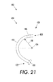
- FIG. 21 another embodiment is shown as ink printer 402 which includes solid ink delivery ink system 404 that is somewhat different than the solid ink delivery system 304 of the ink printer 302 of FIGS. 18-20.
- the solid ink delivery system 404 of FIG. 21 includes a chute 416 which is different than the chute 316 of the solid ink delivery system 304 of FIGS. 18-20.
- the chute 416 is similarly an arcuate chute and is defined by radius RR extending from origin 426.
- the radius RR may be constant or may vary, for example, increase.
- the chute 416 has a path that crosses over itself, or in other words the upper portions of the chute 416 may be positioned over the lower portions of chute 416.
- a chute configuration such as chute 416 may be conservative of space. It should be appreciated that the chute 416 may lie in a single plane or in a plurality of non-parallel planes. In other words, the chute 416 may form, for example, a spiral shape or a helical shape.
- the chute 416 may have any size and shape and opening 428 of the chute 416 may, for example, be rectangular, triangular, pentagonal, or have any other shape.
- the size and shape of the opening 428 of the chute 416 is preferably similar to the size and shape of the solid ink stick 406 to be positioned in the chute 416 so that the stick 406 may freely fall by gravity down the chute 416 from the loading position 420 to delivery position 422 adjacent melting units 408.
- the printer 502 includes a solid ink delivery system 504 that has a chute 516 that includes an arcuate upper portion 574 and a linear lower portion 576.
- the arcuate upper portion 574 may extend from the loading position 520 to the transition position 578 located between the arcuate upper portion 574 and the linear lower portion 576 of the chute 516.
- the arcuate upper portion 574 may be defined by radius RR extending from origin 580.
- the linear lower portion 576 extends from the transition position 578 to delivery position 522 adjacent melting unit 508.
- the linear lower portion 576 as shown in FIG. 22, may be vertical. It should be appreciated that the linear portion 576 may, alternatively, be angled.
- the solid ink stick 506 for use in the printer 502 may be rectangular or may, as is shown in FIG. 22, be arcuate.
- the arcuate shape of the solid ink stick 506 permits the motion of the stick 506 through the arcuate upper portion 574 and the transition position 578 of the chute 516.
- the solid ink stick 506 of the printer 502 has a width CBW and a thickness CBT.
- the thickness CBT is defined by radius RR1 and RR2 extending from origin 582. Radii RR1 and RR2 may be optimized depending on the shape of the arcuate upper portion 574 and the linear lower portion 576 of the chute 516 of the delivery system 504 of the printer 502.
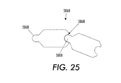
- an alternate solid ink stick 506A is shown for use in the printer 502. It should be appreciated that the solid stick 506A includes a guidance feature 584A that conforms to a mating groove in the chute (not shown).
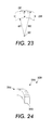
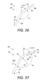
- a solid ink stick 506B is shown for use in prescribed path 518 of the chute 516 of FIG. 22.
- the stick 506B includes a protrusion 586B at one end which mates with a groove 588B in the opposed end of the sticks 5068.
- the protrusion 586B and the groove 588B serve to guide the sticks 506B through the chute 516 of the delivery system 504 of FIG. 22.
- the printer 602 includes a solid ink delivery system 604 which has a chute 616 which is different than the chute 516 of the printer 504 of FIG. 22.
- the chute 616 receives the sticks 606.
- the chute 616 includes a first linear portion 674 that forms an angle ⁇ with respect to the vertical and a second linear portion 676 that forms an angle ⁇ with the vertical. The first portion 674 and the second portion 676 form an angle ⁇ there between.
- the printer 702 includes a solid ink delivery system 704 which has a chute 716 which has three separate portions for advancing sticks 706.
- the chute 716 includes a first linear portion 774 that extends downwardly from loading position 720.
- An arcuate portion 784 connects the first linear portion 774 to a second linear portion 776 that extends downwardly to delivery position 722.
- the first linear portion 774 forms an angle ⁇ with respect to the vertical, while the second linear portion 776 forms an angle ⁇ with respect to the vertical.
- the first linear portion 774 and the second linear portion 776 are connected by the arcuate portion 784 which defines an angle ⁇ there between as well as a radius RR extending from origin 726.
Abstract
Description
- The guide described herein generally relates to high speed printers which have one or more printheads that receive molten ink heated from solid ink sticks or pellets. More specifically, the guide relates to improving the ink transport system design and functionality.
- So called "solid ink" printers encompass various imaging devices, including printers and multi-function platforms and offer many advantages over many other types of high speed or high output document reproduction technologies such as laser and aqueous inkjet approaches. These often include higher document throughput (i.e., the number of documents reproduced over a unit of time), fewer mechanical components needed in the actual image transfer process, fewer consumables to replace, sharper images, as well as being more environmentally friendly (far less packaging waste).
- A schematic diagram for a typical solid ink imaging device is illustrated in FIG. 1. The solid ink imaging device, hereafter simply referred to as a
printer 100 has anink loader 110 which receives and stages solid ink sticks which remain in solid form at room temperatures. The ink stock can be refilled by a user by simply adding more ink as needed to theink loader 110. Separate loader channels are used for the different colors. For, example, only black solid ink is needed for monochrome printing, while solid ink colors of black, cyan, yellow and magenta are typically needed for color printing. Each color is loaded and fed in independent channels of the ink loader. - An
ink melt unit 120 melts the ink by raising the temperature of the ink sufficiently above its melting point. During a melting phase of operation, the leading end of an ink stick contacts a melt plate or heated surface of the melt unit and the ink is melted in that region. The liquefied ink is supplied to a single or group ofprint heads 130 by gravity, pump action, or both. In accordance with the image to be reproduced, and under the control of a printer controller (not shown), a rotatingprint drum 140 receives ink droplets representing the image pixels to be transferred to paper orother media 170 from asheet feeder 160. To facilitate the image transfer process, apressure roller 150 presses themedia 170 against theprint drum 140, whereby the ink is transferred from the print drum to the media. The temperature of the ink can be carefully regulated so that the ink fully solidifies just after the image transfer. - While there may be advantages to the use of solid ink printers compared to other image reproduction technologies, high speed and voluminous printing sometimes creates problems not satisfactorily addressed by the prior art solid ink printing architectures. To meet the large ink volume requirement, ink loaders must have large storage capacity and be able to be replenished by loading ink at any time the loader has capacity for additional ink.
- In typical prior art ink chuck or stick reservoirs, the sticks are positioned end to end in straight or linear channel or chute with a melt head on one end and a spring biased push stick on the other end. As these solid ink printers have high productivity rates, the storage of ample supplies of ink is very desirable. As the space in solid ink printers is limited, finding a location within the printer to accommodate a long straight chute for holding an ample supply of ink is a challenge. The amount of ink that can be accommodated is limited by the physical dimensions of the printer and can not be greater that the amount accommodated by a linear chute diagonally positioned in the printer.
- In view of the above-identified problems and limitations of the prior art and alternate ink and ink loader forms, a solid ink supply system is provided that is adapted for use with solid ink printers.
- According to one embodiment, a solid ink delivery system for use with a solid ink stick for use in solid ink printers is provided. The solid ink delivery system is used for delivering the solid ink stick to a melting station for melting the solid ink stick so that the ink may be transferred to media to form an image on the media. The delivery system includes a guide for guiding the solid ink stick in a prescribed path. The guide defines a loading position to permit the stick to be placed in the guide and a delivery position adjacent the melt station. The stick advances from the loading position to the delivery position in the prescribed path and a portion of the prescribed path is arcuate.
- According to another embodiment, a solid ink printer including a solid ink delivery system for use with a solid ink stick is provided. The solid ink delivery system delivers the solid ink stick to a melting station for melting the solid ink stick so that the ink may be transferred to media to form an image on the media. The delivery system includes a guide for guiding the solid ink stick in a prescribed path. The guide defines a loading position to permit the stick to be placed in the guide and defines a delivery position adjacent the melt station. The stick advances from the loading position to the delivery position in the prescribed path and a portion of the prescribed path is arcuate.
In a further embodiment the prescribed path includes a second portion that is linear.
In a further embodiment the prescribed path includes a second portion that is linear and that defines a first path axis and a third portion that is linear and that defines a second path axis, the second path axis being skewed with respect to the first path axis and the second path axis forms an angle with the first path axis.
In a further embodiment the first mentioned portion is positioned between the second portion and the third portion.
In a further embodiment the prescribed path from the loading position to the delivery position includes a second portion of the prescribed path that extends under a first portion of the prescribed path.
In a further embodiment the prescribed path defines a plurality of planes, at least two planes being skewed with respect to each other.
In a further embodiment at least a portion of the prescribed path is helical.
In a further embodiment the solid ink printer further comprises a drive member for engagement with the stick. - According to yet another embodiment, a solid ink stick adapted for use with solid ink printers having a curved loading device for receiving the stick and advancing the stick toward a melting station in the printer is provided. The stick includes a body defining a longitudinal axis of the body. The longitudinal axis is non linear and the stick is adapted to closely conform to a curved loading device.
In a further embodiment the body has a generally L shape as viewed perpendicular to the longitudinal axis.
In a further embodiment the body has a generally C shape as viewed perpendicular to the longitudinal axis. - As described herein, an ink delivery system for solid ink printers utilizes a curved chute to advance the ink from the loading station to the melting station to transfer ink to one or more printheads. The many additional described features of this ink delivery system, which can be selectively incorporated individually or in any combination, enable many additional printer system opportunities, including lower cost, enlarged ink storage capacity, as well as, less jamming and camming as an alternative (upgrade) or addition (volume/delivery supplement) to more typical ink delivery systems.
- Features of the system described herein will become apparent to those skilled in the art from the following description with reference to the drawings, in which:
- FIG. 1 is a general schematic diagram of a prior art high speed, solid ink printer;
- FIG. 2 is a cutaway perspective view of an embodiment of a solid ink delivery system in position in a solid ink printer for delivering solid ink sticks to printheads of the solid ink printer;
- FIG. 3 is a partial cutaway perspective view of the guide for the ink sticks of the solid ink delivery system of FIG. 2 in position in a solid ink printer for delivering solid ink sticks to printheads of the printer showing the ink delivery system in greater detail;
- FIG. 4 is another cutaway perspective view of the solid ink delivery system of FIG. 2 in position in a solid ink printer for delivering solid ink sticks to printheads of the printer;
- FIG. 5 is a perspective view of the guide assembly of the solid ink delivery system of FIG. 2 for advancing the ink sticks of the solid ink delivery system toward the printheads of the printer;
- FIG. 6 is another perspective view of the guide assembly of the solid ink delivery system of FIG. 2 for advancing the ink sticks of the solid ink delivery system toward the printheads of the printer;
- FIG. 7 is another perspective view of the guide assembly of the solid ink delivery system of FIG. 2 including the drive member for advancing the ink sticks of the solid ink delivery system toward the printheads of the printer;
- FIG. 7A is a partial plan view of a sensor in position in the guide assembly of FIG. 7;
- FIG. 8 is partial perspective view of the guide assembly including the drive member for advancing the ink sticks of the solid ink delivery system of FIG. 2 showing the portion adjacent the print heads in greater detail;
- FIG. 9 is a perspective view of a solid ink stick for use with the guide assembly for advancing the ink sticks of the solid ink delivery system of FIG. 2 toward the print heads of the printer;
- FIG. 10 is a plan view of the solid ink stick of FIG. 9 in position on a flat portion of the drive member of FIG. 7;
- FIG. 11 is an plan view of the solid ink stick of FIG. 9 in position on a curved portion of the drive member of the delivery system of FIG. 7;
- FIG. 12 is a cross sectional view of a drive member and chute of a solid ink delivery system for use in a printing machine with the drive member being not centrally positioned with respect to the chute and the ink stick according to another embodiment;
- FIG. 13 is a perspective view of a flat drive member with a cog for use in a solid ink delivery system of a printing machine according to another embodiment;
- FIG. 14 is a cross sectional view of a D-shaped chute with a drive member of a solid ink delivery system for use in a printing machine according to another embodiment;
- FIG. 15 is a cross sectional view of a triangular-shaped chute with a drive member of a solid ink delivery system for use in a printing machine according to another embodiment;
- FIG. 16 is a cross sectional view of a hexagonal-shaped chute with a drive member of a solid ink delivery system for use in a printing machine according to another embodiment;
- FIG. 17 is a cross sectional view of a pentagonal-shaped chute with a drive member of a solid ink delivery system for use in a printing machine according to another embodiment;
- FIG. 18 is a partial perspective view of another embodiment solid ink delivery system for delivering solid ink stock to a melting station for converting the solid ink into liquid form for delivery to print heads of the printer;
- FIG. 19 is a partial perspective view of the chute of the solid ink delivery system of FIG. 18;
- FIG. 20 is a partial perspective view of an ink stick and the loading station of the chute of FIG. 3;
- FIG. 21 is a partial plan view of another embodiment of the solid ink delivery system with a chute that has a portion that extends underneath another portion of the chute;
- FIG. 22 is a plan view of a further embodiment of the solid ink delivery system in the form of a solid ink delivery system with a chute having a linear portion and a curved portion;
- FIG. 23 is a plan view of the ink stick for use in the chute of the solid ink delivery system of FIG. 22;
- FIG. 24 is a perspective view of another ink stick with a guidance feature for use with a further embodiment of the solid ink delivery system; and
- FIG. 25 is a plan view of another solid ink stick with guidance feature for use with the chute for the solid ink delivery system of FIG. 14;
- FIG. 26 is a plan view of a further embodiment of the solid ink delivery system in the form of a solid ink delivery system with a chute having a first linear portion and a second linear portion; and
- FIG. 27 is a plan view of a further embodiment of the solid ink delivery system in the form of a solid ink delivery system with a chute having a first linear portion, a curved portion and a second linear portion.
- The term "printer" refers, for example, to reproduction devices in general, such as printers, facsimile machines, copiers, and related multi-function products, and the term "print job" refers, for example, to information including the electronic item or items to be reproduced. References to ink delivery or transfer from an ink cartridge or housing to a printhead are intended to encompass the range of intermediate connections, tubes, manifolds and/or other components that may be involved in a printing system but are not immediately significant to the system described herein.
- The general components of a solid ink printer have been described supra. The system described herein includes a solid ink delivery system and a solid ink printer and a solid ink stick for incorporating the same.
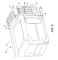
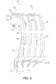
- Referring now to FIG. 2, an embodiment of the solid ink printer with the solid ink delivery system is shown as
printer 202. Theprinter 202 is a multi-color printer. Theprinter 202 utilizes four separate color ink sticks 206 which have respectively the colors black, cyan, magenta and yellow. Theprinter 202 of FIG. 2 also has achute 208 that includes anarcuate portion 207 to increase the stick capacity of thechute 208. The arcuate portion may be comprised of a single or multiple arc axes, including continuously variable 3 dimensional arc paths, any combination of which can be of any length relative to the full arcuate portion. The term arcuate refers to these and any similar, non linear configuration - The
printer 202, as shown in FIG. 2, has aframe 203 which is used to support solidink delivery system 204. The solidink delivery system 204 advances thesticks 206 from loadingstation 224 near the top of thesolid ink printer 202 tomelting station 230 near the bottom of theprinter 202. Theprinter 202 includes a plurality ofchutes 208. Aseparate chute 208 is utilized for each of the four colors: namely cyan, magenta, black and yellow. - As shown in FIG. 2, the
chutes 208 may includelongitudinal openings 209 for viewing the progress of thesticks 206 within thechutes 208 and also to reduce cost and weight. Nudgingmembers 228 may be positioned along thechute 208 for nudging thesticks 206 againstbelt 216. - Referring now to FIGS. 3 & 4, the solid
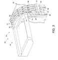
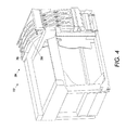
ink delivery system 204 of theprinter 202 is shown in greater detail. The solidink delivery system 204 includes incorporates separate solid ink delivery sub-systems, each consisting, in part, of a load or receiving section, a feed chute and a melt unit.. For example, and as is shown in FIGS. 3 & 4, the solidink delivery system 204 includes a blackink delivery sub-system 260. - The solid
ink delivery system 204 further includes a second, third and fourth solidink delivery sub-system ink delivery system 304.. Each of the solidink delivery sub-systems ink delivery sub-system 260 will be described in greater detail. It should be appreciated that theother sub-systems ink delivery sub-system 260. - The black solid
ink delivery sub-system 260 includeschute 208 for holding a number of ink sticks 306 and guiding them in aprescribed path 210 from loadingstation 224 to themelting station 230. Thechute 208 may have an insertion opening with any suitable shape such that only one color of s an ink stick set may pass through the opening. The black solidink delivery sub-system 260 further includes a drive member in the form ofbelt 216 which provides for engagement with a plurality of the solid ink sticks 206 and extends along a substantial portion of theprescribed path 210 of the solidink delivery sub-system 260. In operation, thechute 208 may be loaded with several sticks. Thebelt 216 may simultaneously contactseveral sticks 206, each stick positioned at a different place in thechute 208. - While the
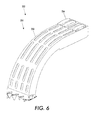
chute 208 may have any suitable shape, for example, and as shown in FIGS. 5 & 6, thechute 208 may include a firstlinear portion 268 adjacent theloading station 224. As shown in FIGS. 5 & 6, the firstlinear portion 268 may be substantially horizontal such that thesolid ink stick 206 may be inserted into theend 256 of thechute 208 in a simple horizontal motion in the top of theprinter 202 or the stick may be inserted vertically through a keying feature (not shown) into the chute and then advanced horizontally. An arcuate portion of the feed path may be short or may be a substantial portion of the path length. The full length of the chute may be arcuate and may consist of different or variable radii. A linear portion of the feed path may likewise be short or a substantial portion of the path length. - To better utilize the space within the
printer 202, thechute 208 may have a shape that is not linear such that a greater number of solid ink sticks 206 may be placed within theprinter 202 than the number possible with a linear chute. For example, and as shown in FIGS. 5 & 6, thechute 208 may include, in addition to the firstlinear portion 268,arcuate portion 207 extending downwardly from the firstlinear portion 268 of thechute 208. Thechute 208 may further include a secondlinear portion 270 extending downwardly from thearcuate portion 207 of thechute 208. The secondlinear portion 270 may be substantially vertical and be positioned over themelting station 230 such that the solid ink sticks 206 may be delivered to themelting station 230 by gravity. - The chute may lay within a single plane, for example,
plane 272. Alternatively, and as shown in FIGS. 5 & 6, thechute 208 may extend through a series of non-parallel planes. For example, and as shown in FIG. 5, thechute 208 may move downwardly and outwardly to anangled plane 274 which is skewed with respect to thevertical plane 272. Theplanes chute 208. - Referring now to FIG. 7, the
drive belt 216 of the solidink delivery system 204 of theprinter 202 is shown in greater detail. Thedrive belt 216 may require that a portion of thebelt 216 have a shape to conform to thechute 208. The conforming shape may be in thearcuate portion 207 of thechute 208, as well as in the firstlinear portion 268 and the secondlinear portion 270 of thechute 208. Thebelt 216 may be driven, for example, by amotor transmission assembly 222 which is used to rotate drivepulley 218. - The
drive belt 216 may, for example, have a circular cross section and be a continuous belt extending from thedrive pulley 218 through a series of inletidler pulleys 220 andchute 208. Nudgingmembers 228 in the form of, for example, pinch rollers may be spring loaded and biased toward thebelt 216 to assure sufficient friction between thebelt 216 and the solid ink sticks 206 such that the solid ink sticks do not fall by gravity and slip away from thebelt 216. - The solid
ink delivery system 204 of theprinter 202 may further include a series of sensors for determining the presence or absence of the solid ink sticks 206 within different portions of thechute 208. Aninlet sensor assembly 276 may be used to indicate additional ink sticks 206 may be added to thechute 208. Theinlet sensor assembly 276 may be positioned nearloading station 224. Alow sensor assembly 278 may be used to indicate a low quantity of ink sticks 206 in thechute 208. Thelow sensor assembly 278 may be positioned spaced from themelt station 230. - An out
sensor assembly 280 may be used to indicate the absence of ink sticks 206 in thechute 208. The outsensor assembly 280 may be positioned adjacent to themelt station 230. Thesensor assemblies chute 208 and transition a switch, such as a micro switch or an optical interrupter. The presence of astick 206 causes the sensors to move fromfirst position 282, as shown in phantom, tosecond position 284, as shown in solid. A sensor or switch may be used to determine whether thesensors first position 282 or in thesecond position 284. Other sensing devices may be used in conjunction with or in place of a mechanical flag system, such as a proximity switch or reflective or retro-reflective optical sensor. - Referring now to FIG. 7A,
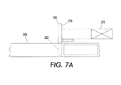
sensor 278 is shown in position in wall of thechute 208. Thesensor 278 pivots about a wall of thechute 208. The presence of astick 206 causes thesensor 278 to move fromfirst position 282, as shown in phantom, tosecond position 284, as shown in solid. A sensor or switch 279 may be used to determine whether thesensor 278 is in thefirst position 282 or in thesecond position 284. - Referring now to FIG. 8, the solid
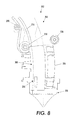
ink delivery system 204 of theprinter 202 is shown in the location around themelt station 230. As shown in FIG. 8, thedrive pulley 218 and thebelt 216 are positioned somewhat away from thesolid ink stick 206 when thesolid ink stick 206 is in themelt station 230. The spacing of thebelt 216 away from thesolid ink stick 206, when thesolid ink stick 206 is in themelt station 230, may permit gravity to be the only factor causing the solid ink sticks 206 to be forced against a melt unit when the belt is stopped. If thebelt 216 continues to run, however,additional sticks 206, if present, may contact thebelt 216 and push against thelower stick 206, urging it toward themelt station 230. - It should be appreciated that, alternatively, the
pulley 218 may be positioned low enough that thesolid ink stick 206 may be in contact with thepulley 218 when thestick 206 is in themelt station 230. With such a configuration, thebelt 216 may insure sufficient forces are exerted on thesolid ink stick 206 to increase the contact pressure of thesolid ink stick 206 against the melt unit. - Referring now to FIG. 9,
solid ink stick 206 for use with theprinter 202 of FIGS. 2-8 is shown in greater detail. Thesolid ink stick 206 as shown in FIG. 9 includes a series of vertical keying features used, among other things, to differentiate sticks of different colors and different printer models. The stick keying features are used to admit or block insertion of the ink through the keyed insertion opening of the solidink delivery system 304. Thesolid ink stick 206 further includes a series of horizontal shapedfeatures 288 for guiding, supporting or limiting feed of theink stick 206 along the chute feedpath.
It should be appreciated that that keying and shaped features can be configured to accomplish the same functions with a horizontal or other alternate loading orientation. - The
solid ink stick 206, as shown in FIG. 9, includes two spaced-apart pairs of spaced-apartflat portions 290, one pair on each end of thestick 206, for accommodating the linear portions of the feed path, as well as a centrally located pair of spaced apartarcuate portions 292, to accommodate the curved or arcuate portion of ink feed path. Theink stick groove 250 likewise has linear and arcuate portions. - Referring now to FIG. 10, the
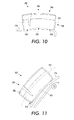
solid ink stick 206 is shown in position on a linear portion of thebelt 216 of the solidink delivery system 204 of theprinter 202. Thesolid ink stick 206 contacts thebelt 216 at theend portions 290 of thesolid ink stick 206 and thegroove 250 formed in thesolid ink stick 206 cooperates with thebelt 216 to advance thestick 206. As shown in FIG. 10, thesolid ink stick 206 is arcuate or curved alonglongitudinal axis 294. - Referring to FIG. 11, the
solid ink stick 206 is shown in position along an arcuate portion of thebelt 216. As shown in FIG. 11, the centralarcuate portion 292 of thesolid ink stick 206 engages with thebelt 216. - Referring now to FIG. 12, yet another embodiment is shown as
solid ink printer 202A which utilizes a solidink delivery system 204A. The solidink delivery system 204A is similar to thesolid ink system 204 of FIGS. 7-14 except that the solidink delivery system 204A includes asolid ink stick 206A which has astick belt guide 250A which is not central within thestick 206A. Theend 256A of theguide 208A includes a key 258A which likewise is not central such that thestick 206A matches the key 258A. - Referring now to FIG. 13, yet another embodiment is shown as
solid ink printer 202B which includes a solidink delivery system 204B which includes abelt 216B which has a rectangular cross section or is flat. It should be appreciated that thebelt 216B may includecogs 291B which are formed on a surface of thebelt 216B for contact with the sticks 206B. - Referring now to FIG. 14, yet another embodiment, is shown as
solid ink printer 202C which includes solidink delivery system 204C which is different than the solidink delivery system 204 of FIGS. 2-8 in that the solidink delivery system 204C includes achute 208C which is semi-circular and has astick 206C which mates with thechute 208C. - Referring now to FIG. 15, another embodiment is shown as
solid ink printer 202D which includes a solidink delivery system 204D which is different than the solidink delivery system 204 of FIGS. 7-14 in that solidink delivery system 204D includes achute 208D which is triangular. Thetriangular chute 208D receives a triangularsolid ink stick 206D. - Referring now to FIG. 16, yet another embodiment is shown as
solid ink printer 202E which includes a solidink delivery system 204E which is different than the solid ink delivery system of 204 of FIGS. 2-8 in that the solidink delivery system 204E includes achute 208E which is hexagonal and cooperates with a hexagonalsolid ink stick 206E. - Referring now to FIG. 17, yet another embodiment is shown as
solid ink printer 202F which includes a solidink delivery system 204F which is different than the solidink delivery system 204 of FIGS. 2-8 in that the solidink delivery system 204F includes achute 208F which is pentagonal and cooperates with astick 206F which is also pentagonal. - The chute configuration examples shown in the various alternative embodiments are depicted as fully matching the ink shape at least in one sectional axis. The chute need not match the ink shape in this fashion and need not be completely encircling. One or more sides may be fully or partially open or differently shaped. The side surfaces of the chute do not need to be continuous over the chute length. The chute need only provide an appropriate level of support and/or guidance to complement reliable loading and feeding of ink sticks intended for use in any configuration.
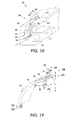
- Referring now to FIG. 18, a
solid ink printer 302 is shown. Theprinter 302 includes a solidink delivery system 304 for use with asolid ink stick 306. Theprinter 302 includes the solidink delivery system 304 for delivering thesolid ink stick 306 to a melting station where amelting unit 308 is used to melt thesolid ink stick 306. The ink in thesolid ink stick 306 is transferred from a solid to a liquid and theliquid ink 310 is transferred to media, for example, a sheet ofpaper 312, by adrum 314 to form animage 315 on thepaper 312. The solidink delivery system 304 includes aguide 316 for guiding thesolid ink stick 306 in aprescribed path 318. Theguide 316 may be, for example, in the form of a chute. Theguide 316 defines aloading position 320 to permit thesolid ink stick 306 to be placed into the guide orchute 316. - The
chute 316 also defines adelivery position 322 adjacent to themelting unit 308. Theloading position 320 is located above thedelivery position 322. Thesolid ink stick 306 is slideably fitted to thechute 316 where by only gravity advances thesolid ink stick 306 from theloading position 320 to thedelivery position 322. - It should be appreciated that the
chute 316 may have any suitable shape such that thesticks 306 fall by gravity fromloading position 320, that may be positioned near, for example, printertop work surface 324, toward themelting unit 308. Thechute 316 may include linear and arcuate portions or may, as is shown in FIG. 18, be of a continuous arcuate shape defined by a radius R extending from theorigin 326. It should be appreciated thatorigin 326 may be positioned anywhere with respect to thechute 316 and that the radius R may be constant, or, as is shown in FIG. 18, vary such that the radius R may increase such that the chute is virtually vertical near themelting unit 308. - Referring now to FIG. 19, it should be appreciated that the
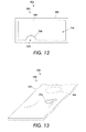
chute 316 forms astick opening 328 in a suitable size and shape and to provide for the uniform movement of thesticks 306 down thechute 316 along thepath 318. To avoid cross loading or jamming of thesticks 306 in thechute 316, thesticks 306 may have anexternal periphery 330 which closely conforms withinternal periphery 332 formed in the stick opening 328 of thechute 316. - For example, and as is shown in FIG. 19, the
sticks 306 may be rectangular and the stick opening 328 of thechute 316 may be rectangular and slightly larger than thesticks 306 to provide the ability of thesticks 306 to fall by gravity down thechute 316. For example, and as shown in FIG. 19, the sticks have a stick length BL, a stick height BH, and a stick width BW. Thestick opening 328 of thechute 316 may be defined by a chute height CH slightly larger than the stick height BH and a chute width CW slightly wider than the stick width BW. - Further to assure that the
sticks 306 fall by gravity down theopening 328 of thechute 316 and as is shown in FIG. 19, thebottom surface 334 of thechute opening 328 may form an angle α with the horizontal plane such that the force of gravity may exceed the coefficient of friction between thesticks 306 and the chutelower surface 334 such that the sticks advance along thepath 318 from theloading position 320 to thedelivery position 322. A non-stick surface may be applied to thebottom surface 334, such as Teflon®, a trademark of E. I. DuPont de Nemours and Company. - Referring now to FIG. 20, the
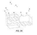
stick 306 and thechute 316 of the solidink delivery system 304 of theprinter 302 is shown in greater detail near theloading position 320 of the solidink delivery system 304. To assure the propersolid ink stick 306 is placed in thechute 316, thestick 306 and thechute 316 may have matched keying systems in the form of, for example,bosses 336 located on thestick 306 that mate withrecesses 338 formed in thechute 316. Thebosses 336 and recesses 338 serve to assure that only the proper solid ink stick is feed into thechute 316. This is particularly important in color machines where the improper color of ink stick should not be loaded into the wrong chute. - Referring again to FIG. 18, the
printer 302, as shown in FIG. 3, is a color ink printer. Thechute 316, as shown in FIG. 18, include a firstblack chute 340, a secondcyan ink chute 342, a thirdmagenta ink chute 344, and a fourthyellow ink chute 346. The fourink chutes - Referring now to FIG. 21, another embodiment is shown as
ink printer 402 which includes solid inkdelivery ink system 404 that is somewhat different than the solidink delivery system 304 of theink printer 302 of FIGS. 18-20. The solidink delivery system 404 of FIG. 21 includes achute 416 which is different than thechute 316 of the solidink delivery system 304 of FIGS. 18-20. Thechute 416 is similarly an arcuate chute and is defined by radius RR extending fromorigin 426. The radius RR may be constant or may vary, for example, increase. - The
chute 416, as shown in FIG. 21, has a path that crosses over itself, or in other words the upper portions of thechute 416 may be positioned over the lower portions ofchute 416. Such a chute configuration such aschute 416 may be conservative of space. It should be appreciated that thechute 416 may lie in a single plane or in a plurality of non-parallel planes. In other words, thechute 416 may form, for example, a spiral shape or a helical shape. - The
chute 416 may have any size and shape and opening 428 of thechute 416 may, for example, be rectangular, triangular, pentagonal, or have any other shape. The size and shape of theopening 428 of thechute 416 is preferably similar to the size and shape of thesolid ink stick 406 to be positioned in thechute 416 so that thestick 406 may freely fall by gravity down thechute 416 from theloading position 420 todelivery position 422adjacent melting units 408. - Referring now to FIG. 22, yet another embodiment is shown as
solid ink printer 502. Theprinter 502 includes a solidink delivery system 504 that has achute 516 that includes an arcuateupper portion 574 and a linearlower portion 576. The arcuateupper portion 574 may extend from theloading position 520 to thetransition position 578 located between the arcuateupper portion 574 and the linearlower portion 576 of thechute 516. The arcuateupper portion 574 may be defined by radius RR extending fromorigin 580. The linearlower portion 576 extends from thetransition position 578 todelivery position 522adjacent melting unit 508. The linearlower portion 576, as shown in FIG. 22, may be vertical. It should be appreciated that thelinear portion 576 may, alternatively, be angled. - The
solid ink stick 506 for use in theprinter 502 may be rectangular or may, as is shown in FIG. 22, be arcuate. The arcuate shape of thesolid ink stick 506 permits the motion of thestick 506 through the arcuateupper portion 574 and thetransition position 578 of thechute 516. - Referring now to FIG. 23, the
solid ink stick 506 of theprinter 502 is shown in greater detail. Thesolid ink stick 506 has a width CBW and a thickness CBT. The thickness CBT is defined by radius RR1 and RR2 extending fromorigin 582. Radii RR1 and RR2 may be optimized depending on the shape of the arcuateupper portion 574 and the linearlower portion 576 of thechute 516 of thedelivery system 504 of theprinter 502. - Referring now to FIG. 24, an alternate
solid ink stick 506A is shown for use in theprinter 502. It should be appreciated that thesolid stick 506A includes aguidance feature 584A that conforms to a mating groove in the chute (not shown). - Referring now to FIG. 25, a
solid ink stick 506B is shown for use inprescribed path 518 of thechute 516 of FIG. 22. Thestick 506B includes aprotrusion 586B at one end which mates with agroove 588B in the opposed end of the sticks 5068. Theprotrusion 586B and thegroove 588B serve to guide thesticks 506B through thechute 516 of thedelivery system 504 of FIG. 22. - Referring now to FIG. 26, yet another embodiment is shown as
printer 602. Theprinter 602 includes a solidink delivery system 604 which has achute 616 which is different than thechute 516 of theprinter 504 of FIG. 22. Thechute 616 receives thesticks 606. Thechute 616 includes a firstlinear portion 674 that forms an angle ααα with respect to the vertical and a secondlinear portion 676 that forms an angle ββ with the vertical. Thefirst portion 674 and thesecond portion 676 form an angle θ there between. - Referring now to FIG. 27, another embodiment is shown as
printer 702.
Theprinter 702 includes a solidink delivery system 704 which has achute 716 which has three separate portions for advancingsticks 706. Thechute 716 includes a firstlinear portion 774 that extends downwardly fromloading position 720. Anarcuate portion 784 connects the firstlinear portion 774 to a secondlinear portion 776 that extends downwardly todelivery position 722. The firstlinear portion 774 forms an angle αααα with respect to the vertical, while the secondlinear portion 776 forms an angle βββ with respect to the vertical. The firstlinear portion 774 and the secondlinear portion 776 are connected by thearcuate portion 784 which defines an angle θθ there between as well as a radius RR extending fromorigin 726.
Claims (10)
- A solid ink delivery system for use with a solid ink stick for use in solid ink printers, said solid ink delivery system for delivering the stick to a melting station for melting the stick so that the ink may be transferred to media to form an image thereon, said delivery system comprising a guide for guiding the stick in a prescribed path:
wherein said guide defines a loading position to permit the stick to be placed in the guide;
wherein said guide defines a delivery position adjacent the melt station; and
wherein the stick advances from the loading position to the delivery position in the prescribed path; and
wherein at least a portion of the prescribed path is arcuate. - The solid ink delivery system of claim 1, wherein the prescribed path includes a second portion that is linear.
- The solid ink delivery system of claim 1, wherein the prescribed path includes a second portion that is linear and that defines a first path axis and a third portion that is linear and that defines a second path axis, the second path axis being skewed with respect to the first path axis and the second path axis forms an angle with the first path axis.
- The solid ink delivery system of claim 3, wherein the first mentioned portion is positioned between the second portion and the third portion.
- The solid ink delivery system of claim 1, wherein the prescribed path from the loading position to the delivery position includes a second portion of the prescribed path that extends under a first portion of the prescribed path.
- The solid ink delivery system of claim 1, wherein the prescribed path defines a plurality of planes, at least two planes being skewed with respect to each other.
- The solid ink delivery system of claim 1, wherein at least a portion of the prescribed path is helical.
- The solid ink delivery system of claim 1, further comprising a drive member for engagement with the solid ink stick.
- A solid ink printer including a solid ink delivery system for use with a solid ink stick, said solid ink delivery system for delivering the stick to a melting station for melting the stick so that the ink may be transferred to media to form an image thereon, said delivery system comprising a guide for guiding the stick in a prescribed path:
wherein said guide defines a loading position to permit the stick to be placed in the guide;
wherein said guide defines a delivery position adjacent the melt station; and
wherein the stick advances from the loading position to the delivery position in the prescribed path; and
wherein at least a portion of the prescribed path is arcuate. - A solid ink stick adapted for use with solid ink printers having a curved loading device for receiving the stick and advancing the stick toward a melting station in the printer, said stick comprising a body defining a longitudinal axis thereof, the longitudinal axis being non linear and adapted to closely conform to a curved loading device.
Applications Claiming Priority (1)
| Application Number | Priority Date | Filing Date | Title |
|---|---|---|---|
| US11/602,937 US7794072B2 (en) | 2006-11-21 | 2006-11-21 | Guide for printer solid ink transport and method |
Publications (3)
| Publication Number | Publication Date |
|---|---|
| EP1925455A2 true EP1925455A2 (en) | 2008-05-28 |
| EP1925455A3 EP1925455A3 (en) | 2013-07-10 |
| EP1925455B1 EP1925455B1 (en) | 2015-04-29 |
Family
ID=39154062
Family Applications (1)
| Application Number | Title | Priority Date | Filing Date |
|---|---|---|---|
| EP20070121105 Expired - Fee Related EP1925455B1 (en) | 2006-11-21 | 2007-11-20 | Guide for Printer Solid Ink Transport |
Country Status (5)
| Country | Link |
|---|---|
| US (1) | US7794072B2 (en) |
| EP (1) | EP1925455B1 (en) |
| JP (1) | JP4943996B2 (en) |
| CN (2) | CN101186152B (en) |
| BR (1) | BRPI0704058A (en) |
Families Citing this family (12)
| Publication number | Priority date | Publication date | Assignee | Title |
|---|---|---|---|---|
| US7857439B2 (en) * | 2006-06-23 | 2010-12-28 | Xerox Corporation | Solid ink stick with interface element |
| US7878636B2 (en) * | 2006-12-12 | 2011-02-01 | Xerox Corporation | Solid ink stick chute for printer solid ink transport with mating solid ink stick chute |
| US7726798B2 (en) * | 2006-12-15 | 2010-06-01 | Xerox Corporation | Printer solid ink transport and method |
| US7976118B2 (en) | 2007-10-22 | 2011-07-12 | Xerox Corporation | Transport system for providing a continuous supply of solid ink to a melting assembly in a printer |
| US7891792B2 (en) * | 2007-11-06 | 2011-02-22 | Xerox Corporation | Solid ink stick with transition indicating region |
| US7887173B2 (en) | 2008-01-18 | 2011-02-15 | Xerox Corporation | Transport system having multiple moving forces for solid ink delivery in a printer |
| US8240830B2 (en) | 2010-03-10 | 2012-08-14 | Xerox Corporation | No spill, feed controlled removable container for delivering pelletized substances |
| US8317308B2 (en) * | 2010-07-14 | 2012-11-27 | Xerox Corporation | Solid ink stick with motion control inset |
| US8579426B2 (en) * | 2010-12-17 | 2013-11-12 | Xerox Corporation | Method and system for delivering solid-ink pellets |
| US8814336B2 (en) | 2011-12-22 | 2014-08-26 | Xerox Corporation | Solid ink stick configuration |
| US8777386B2 (en) | 2012-10-17 | 2014-07-15 | Xerox Corporation | Solid ink stick having identical identifying features on a plurality of edges |
| US8727478B2 (en) | 2012-10-17 | 2014-05-20 | Xerox Corporation | Ink loader having optical sensors to identify solid ink sticks |
Citations (1)
| Publication number | Priority date | Publication date | Assignee | Title |
|---|---|---|---|---|
| JPH07241997A (en) | 1994-03-04 | 1995-09-19 | Hitachi Koki Co Ltd | Solid ink supply device |
Family Cites Families (120)
| Publication number | Priority date | Publication date | Assignee | Title |
|---|---|---|---|---|
| US3656360A (en) | 1968-04-22 | 1972-04-18 | Goodyear Tire & Rubber | Polyurethane belts |
| US4667206A (en) * | 1984-10-15 | 1987-05-19 | Deyoung Thomas W | Ink jet apparatus and method of operating the ink jet apparatus wherein phase change ink is supplied in solid-state form |
| US4636803A (en) | 1984-10-16 | 1987-01-13 | Exxon Printing Systems, Inc. | System to linearly supply phase change ink jet |
| US4682185A (en) * | 1984-11-08 | 1987-07-21 | Martner John G | Ink jet method and apparatus utilizing a web of hot melt ink |
| EP0338590B1 (en) | 1988-04-22 | 1996-07-17 | Seiko Epson Corporation | Ink jet type recording apparatus and method |
| US5181049A (en) * | 1989-11-09 | 1993-01-19 | Dataproducts Corporation | Phase change ink replenishment system |
| JPH03265671A (en) | 1990-03-15 | 1991-11-26 | Brother Ind Ltd | Solid ink |
| JP2663077B2 (en) | 1991-03-25 | 1997-10-15 | テクトロニクス・インコーポレイテッド | Ink supply device |
| US5223860A (en) * | 1991-06-17 | 1993-06-29 | Tektronix, Inc. | Apparatus for supplying phase change ink to an ink jet printer |
| US5689288A (en) * | 1994-06-17 | 1997-11-18 | Tektronix, Inc. | Ink level sensor |
| US5510821B1 (en) * | 1994-09-20 | 2000-05-02 | Tektronix Inc | Solid ink stick |
| USD371157S (en) | 1995-01-03 | 1996-06-25 | Tektronix, Inc. | Solid ink stick color printer |
| USD371801S (en) | 1995-01-20 | 1996-07-16 | Tektronix, Inc. | Solid ink stick for color printer |
| USD371802S (en) | 1995-01-20 | 1996-07-16 | Tektronix, Inc. | Solid ink stick for a color printer |
| USD380771S (en) | 1995-01-20 | 1997-07-08 | Tektronix, Inc. | Solid ink stick for a color printer |
| USD383153S (en) | 1995-01-20 | 1997-09-02 | Tektronix, Inc. | Solid ink stick for a color printer |
| USD373139S (en) | 1995-05-11 | 1996-08-27 | Tektronix, Inc. | Solid ink stick for a color printer |
| USD383154S (en) | 1995-05-11 | 1997-09-02 | Tektronix, Inc. | Solid ink stick for a color printer |
| USD372270S (en) | 1995-05-11 | 1996-07-30 | Tektronix, Inc. | Solid ink stick for a color printer |
| USD372268S (en) | 1995-05-11 | 1996-07-30 | Tektronix, Inc. | Solid ink stick for a color printer |
| US5761903A (en) * | 1996-03-04 | 1998-06-09 | Straka; Benedict J. | Loop combustion system |
| US5784089A (en) * | 1996-03-07 | 1998-07-21 | Tektronix, Inc. | Melt plate design for a solid ink printer |
| US5734402A (en) * | 1996-03-07 | 1998-03-31 | Tekronix, Inc. | Solid ink stick feed system |
| US5861903A (en) | 1996-03-07 | 1999-01-19 | Tektronix, Inc. | Ink feed system |
| USD379471S (en) | 1996-04-18 | 1997-05-27 | Tektronix, Inc. | Solid ink stick for a color printer |
| USD379470S (en) | 1996-04-18 | 1997-05-27 | Tektronix, Inc. | Solid ink stick for a color printer |
| USD379640S (en) | 1996-04-18 | 1997-06-03 | Tektronix, Inc. | Solid ink stick for a color printer |
| USD379639S (en) | 1996-04-18 | 1997-06-03 | Tektronix, Inc. | Solid ink stick for a color printer |
| US6053608A (en) * | 1996-07-24 | 2000-04-25 | Brother Kogyo Kabushiki Kaisha | Ink pellet with step configuration including slidable bearing surfaces |
| US5917528A (en) * | 1996-09-05 | 1999-06-29 | Tektronix, Inc. | Solid ink stick supply apparatus and method |
| JPH10146961A (en) * | 1996-11-15 | 1998-06-02 | Brother Ind Ltd | Head of hot melt ink-jet printer |
| US6109803A (en) | 1997-02-13 | 2000-08-29 | Brother Kogyo Kabushiki Kaisha | Information recording method and printer |
| USD403352S (en) | 1997-03-10 | 1998-12-29 | Tektronix, Inc. | Solid ink stick for a color printer |
| USD403699S (en) | 1997-03-10 | 1999-01-05 | Tektronix, Inc. | Solid ink stick for a color printer |
| USD409235S (en) | 1997-03-10 | 1999-05-04 | Tektronix, Inc. | Solid ink stick for a color printer |
| USD416936S (en) | 1997-03-10 | 1999-11-23 | Tektronix, Inc. | Solid ink stick for a color printer |
| US5988805A (en) * | 1997-03-10 | 1999-11-23 | Tektronix, Inc | Chiral shaped ink sticks |
| USD407742S (en) | 1997-03-10 | 1999-04-06 | Tektronix, Inc. | Solid ink stick for a color printer |
| USD402308S (en) | 1997-03-10 | 1998-12-08 | Tektronix, Inc. | Solid ink stick for a color printer |
| USD410026S (en) | 1997-03-10 | 1999-05-18 | Tektronix, Inc. | Solid ink stick for a color printer |
| USD403351S (en) | 1997-03-10 | 1998-12-29 | Tektronix, Inc. | Solid ink stick for a color printer |
| JPH11115213A (en) * | 1997-10-16 | 1999-04-27 | Brother Ind Ltd | Ink jet printer |
| USD407110S (en) | 1998-01-06 | 1999-03-23 | Tektronix, Inc. | Solid ink stick for a color printer |
| USD407109S (en) | 1998-01-06 | 1999-03-23 | Tektronix, Inc. | Solid ink stick for a color printer |
| USD407743S (en) | 1998-01-06 | 1999-04-06 | Tektronix, Inc. | Solid ink stick for a color printer |
| USD408849S (en) | 1998-01-06 | 1999-04-27 | Tektronix, Inc. | Solid ink stick for a color printer |
| USD413625S (en) | 1998-01-06 | 1999-09-07 | Tektronix, Inc. | Solid ink stick for a color printer |
| USD407745S (en) | 1998-01-22 | 1999-04-06 | Tektronix, Inc. | Solid ink stick for a color printer |
| USD407111S (en) | 1998-01-22 | 1999-03-23 | Tektronix, Inc. | Solid ink stick for a color printer |
| USD412527S (en) | 1998-05-05 | 1999-08-03 | Tektronix, Inc. | Solid ink stick for a color printer |
| USD412528S (en) | 1998-05-05 | 1999-08-03 | Tektronix, Inc. | Solid ink stick for a color printer |
| USD410490S (en) | 1998-05-05 | 1999-06-01 | Tektronix, Inc. | Solid ink stick for a color printer |
| USD409237S (en) | 1998-05-05 | 1999-05-04 | Tektronix, Inc. | Solid ink stick for a color printer |
| USD414200S (en) | 1998-07-30 | 1999-09-21 | Tektronix, Inc. | Solid ink stick for a color printer |
| USD415193S (en) | 1998-07-31 | 1999-10-12 | Tektronix, Inc. | Solid ink stick for a color printer |
| USD412934S (en) | 1998-07-31 | 1999-08-17 | Tektronix, Inc. | Solid ink stick for a color printer |
| JP4444484B2 (en) | 1999-11-22 | 2010-03-31 | オセ−テクノロジーズ・ベー・ヴエー | Method and system for supplying hot melt ink to a printer |
| USD440248S1 (en) | 1999-12-03 | 2001-04-10 | Xerox Corporation | Solid ink stick for a color printer |
| USD440249S1 (en) | 1999-12-03 | 2001-04-10 | Xerox Corporation | Solid ink stick for a color printer |
| USD436124S1 (en) | 1999-12-03 | 2001-01-09 | Xerox Corporation | Solid ink stick for a color printer |
| USD436989S1 (en) | 1999-12-03 | 2001-01-30 | Xerox Corporation | Solid ink stick for a color printer |
| NL1014294C2 (en) | 2000-02-04 | 2001-08-07 | Ocu Technologies B V | Melting device and an inkjet printer provided with such a melting device. |
| JP4044755B2 (en) * | 2000-12-12 | 2008-02-06 | 三星電子株式会社 | Nonvolatile semiconductor memory device and program method thereof |
| USD453786S1 (en) | 2001-04-26 | 2002-02-19 | Xerox Corporation | Solid ink stick for solid ink printers |
| USD453787S1 (en) | 2001-04-26 | 2002-02-19 | Xerox Corporation | Solid ink stick for solid ink printers |
| US6772764B2 (en) * | 2001-10-06 | 2004-08-10 | Handle With Care, Inc. | Apparatus and method for transporting and securing a restrained person |
| US6719419B2 (en) * | 2002-04-29 | 2004-04-13 | Xerox Corporation | Feed channel keying for solid ink stick feed |
| US6857732B2 (en) | 2002-04-29 | 2005-02-22 | Xerox Corporation | Visible identification of solid ink stick |
| US20030202066A1 (en) * | 2002-04-29 | 2003-10-30 | Xerox Corporation | Solid ink stick with efficient aspect ratio |
| US6840613B2 (en) * | 2002-04-29 | 2005-01-11 | Xerox Corporation | Guide for solid ink stick feed |
| US6672716B2 (en) | 2002-04-29 | 2004-01-06 | Xerox Corporation | Multiple portion solid ink stick |
| US6840612B2 (en) * | 2002-04-29 | 2005-01-11 | Xerox Corporation | Guide for solid ink stick feed |
| US6893121B2 (en) | 2002-04-29 | 2005-05-17 | Xerox Corporaton | Solid ink stick set identification |
| US6739713B2 (en) * | 2002-04-29 | 2004-05-25 | Xerox Corporation | Guide for solid ink stick feed |
| US6722764B2 (en) * | 2002-04-29 | 2004-04-20 | Xerox Corporation | Feed guidance and identification for ink stick |
| US6761444B2 (en) * | 2002-04-29 | 2004-07-13 | Xerox Corporation | Channel keying for solid ink stick insertion |
| US6874880B2 (en) | 2002-04-29 | 2005-04-05 | Xerox Corporation | Solid ink stick with identifiable shape |
| US6755517B2 (en) * | 2002-04-29 | 2004-06-29 | Xerox Corporation | Alignment feature for solid ink stick |
| US6761443B2 (en) * | 2002-04-29 | 2004-07-13 | Xerox Corporation | Keying feature for solid ink stick |
| US6648435B1 (en) * | 2002-05-30 | 2003-11-18 | Xerox Corporation | Load and feed apparatus for solid ink |
| US6705710B2 (en) * | 2002-05-30 | 2004-03-16 | Xerox Corporation | Load and feed apparatus for solid ink |
| US6565201B1 (en) * | 2002-05-30 | 2003-05-20 | Xerox Corporation | Load and feed apparatus for solid ink |
| US6572225B1 (en) * | 2002-05-30 | 2003-06-03 | Xerox Corporation | Load and feed apparatus for solid ink |
| US6679591B2 (en) * | 2002-05-30 | 2004-01-20 | Xerox Corporation | Load and feed apparatus for solid ink |
| US6709094B2 (en) * | 2002-05-30 | 2004-03-23 | Xerox Corporation | Load and feed apparatus for solid ink |
| US6561636B1 (en) * | 2002-05-30 | 2003-05-13 | Xerox Corporation | Load and feed apparatus for solid ink |
| US7104635B2 (en) * | 2002-05-30 | 2006-09-12 | Xerox Corporation | Load and feed apparatus for solid ink |
| US6543867B1 (en) * | 2002-05-30 | 2003-04-08 | Xerox Corporation | Load and feed apparatus for solid ink |
| US6565200B1 (en) * | 2002-05-30 | 2003-05-20 | Xerox Corporation | Load and feed apparatus for solid ink |
| US6719413B2 (en) * | 2002-05-30 | 2004-04-13 | Xerox Corporation | Load and feed apparatus for solid ink |
| USD482721S1 (en) | 2002-09-25 | 2003-11-25 | Xerox Corporation | Color ink stick for solid ink printer |
| USD482062S1 (en) | 2002-09-25 | 2003-11-11 | Xerox Corporation | Color ink stick for solid ink printer |
| USD481759S1 (en) | 2002-09-25 | 2003-11-04 | Xerox Corporation | Color ink stick for solid ink printer |
| USD483404S1 (en) | 2002-09-25 | 2003-12-09 | Xerox Corporation | Color ink stick for solid ink printer |
| USD481758S1 (en) | 2002-09-25 | 2003-11-04 | Xerox Corporation | Color ink stick for solid ink printer |
| USD482389S1 (en) | 2002-09-25 | 2003-11-18 | Xerox Corporation | Color ink stick for solid ink printer |
| USD481757S1 (en) | 2002-09-25 | 2003-11-04 | Xerox Corporation | Color ink stick for solid ink printer |
| USD482722S1 (en) | 2002-09-25 | 2003-11-25 | Xerox Corporation | Color ink stick for solid ink printer |
| USD482720S1 (en) | 2002-09-25 | 2003-11-25 | Xerox Corporation | Color ink stick for solid ink printer |
| USD483062S1 (en) | 2002-09-25 | 2003-12-02 | Xerox Corporation | Color ink stick for solid ink printer |
| USD483063S1 (en) | 2002-09-25 | 2003-12-02 | Xerox Corporation | Color ink stick for solid ink printer |
| USD482388S1 (en) | 2002-09-25 | 2003-11-18 | Xerox Corporation | Color ink stick for solid ink printer |
| USD482063S1 (en) | 2002-09-25 | 2003-11-11 | Xerox Corporation | Color ink stick for solid ink printer |
| USD478621S1 (en) | 2002-09-25 | 2003-08-19 | Xerox Corporation | Color ink stick for solid ink printer |
| USD479368S1 (en) | 2002-09-25 | 2003-09-02 | Xerox Corporation | Color ink stick for solid ink printer |
| USD478347S1 (en) | 2002-09-25 | 2003-08-12 | Xerox Corporation | Color ink stick for solid ink printer |
| NL1022004C2 (en) | 2002-11-27 | 2004-05-28 | Oce Tech Bv | Inkjet printer provided with a device for dosing ink pellets. |
| US6905201B2 (en) * | 2002-12-16 | 2005-06-14 | Xerox Corporation | Solid phase change ink melter assembly and phase change ink image producing machine having same |
| US6824241B2 (en) * | 2002-12-16 | 2004-11-30 | Xerox Corporation | Ink jet apparatus |
| US6866375B2 (en) * | 2002-12-16 | 2005-03-15 | Xerox Corporation | Solid phase change ink melter assembly and phase change ink image producing machine having same |
| US6746113B1 (en) * | 2002-12-16 | 2004-06-08 | Xerox Corporation | Solid phase change ink pre-melter assembly and a phase change ink image producing machine having same |
| US6929360B2 (en) * | 2003-02-14 | 2005-08-16 | Xerox Corporation | Printer solid ink stick removal access feature |
| US6895191B2 (en) * | 2003-05-13 | 2005-05-17 | Xerox Corporation | Insertion verification of replaceable module of printing apparatus |
| US6877951B1 (en) * | 2003-09-23 | 2005-04-12 | Essam T. Awdalla | Rotary ram-in compressor |
| US6981754B2 (en) | 2003-12-30 | 2006-01-03 | Xerox Corporation | Ink delivery and printing method for phasing printing systems |
| US7011399B2 (en) | 2004-01-05 | 2006-03-14 | Xerox Corporation | Low thermal mass, variable watt density formable heaters for printer applications |
| US20050151814A1 (en) * | 2004-01-12 | 2005-07-14 | Xerox Corporation | Guide for solid ink stick feed |
| US7438402B2 (en) | 2006-01-03 | 2008-10-21 | Xerox Corporation | Rolling ink stick |
| US7695126B2 (en) | 2006-10-17 | 2010-04-13 | Xerox Corporation | Ink loader mechanism using an ink stick carrier |
| US7780283B2 (en) | 2006-11-07 | 2010-08-24 | Xerox Corporation | Independent keying and guidance for solid ink sticks |
-
2006
- 2006-11-21 US US11/602,937 patent/US7794072B2/en not_active Expired - Fee Related
-
2007
- 2007-11-15 JP JP2007296233A patent/JP4943996B2/en not_active Expired - Fee Related
- 2007-11-20 EP EP20070121105 patent/EP1925455B1/en not_active Expired - Fee Related
- 2007-11-21 CN CN2007103051772A patent/CN101186152B/en not_active Expired - Fee Related
- 2007-11-21 CN CN201110133994.0A patent/CN102248803B/en not_active Expired - Fee Related
- 2007-11-21 BR BRPI0704058-0A patent/BRPI0704058A/en not_active IP Right Cessation
Patent Citations (1)
| Publication number | Priority date | Publication date | Assignee | Title |
|---|---|---|---|---|
| JPH07241997A (en) | 1994-03-04 | 1995-09-19 | Hitachi Koki Co Ltd | Solid ink supply device |
Also Published As
| Publication number | Publication date |
|---|---|
| EP1925455B1 (en) | 2015-04-29 |
| CN101186152B (en) | 2011-07-06 |
| JP2008126659A (en) | 2008-06-05 |
| CN102248803B (en) | 2014-12-17 |
| EP1925455A3 (en) | 2013-07-10 |
| US20080117265A1 (en) | 2008-05-22 |
| CN101186152A (en) | 2008-05-28 |
| US7794072B2 (en) | 2010-09-14 |
| CN102248803A (en) | 2011-11-23 |
| BRPI0704058A (en) | 2008-07-08 |
| JP4943996B2 (en) | 2012-05-30 |
Similar Documents
| Publication | Publication Date | Title |
|---|---|---|
| EP1925455B1 (en) | Guide for Printer Solid Ink Transport | |
| EP1925452B1 (en) | Solid Ink Stick Features for Printer Ink Transport and Method | |
| EP1925451B1 (en) | Transport system for solid ink in a printer | |
| EP1359016B1 (en) | Guide for solid ink stick feed | |
| EP2065207B1 (en) | Recording device having a conveying unit that conveys a recording medium | |
| US7762655B2 (en) | Printer ink delivery system | |
| US7976144B2 (en) | System and method for delivering solid ink sticks to a melting device through a non-linear guide | |
| US7878636B2 (en) | Solid ink stick chute for printer solid ink transport with mating solid ink stick chute | |
| JP4277224B2 (en) | Paper feeding device and image recording apparatus having the same | |
| US7726798B2 (en) | Printer solid ink transport and method | |
| US7651210B2 (en) | Transport system for solid ink for cooperation with melt head in a printer | |
| US6666536B2 (en) | Ink jet device with movable platen | |
| US20070140708A1 (en) | Image forming apparatus and associated methodology of indicating an available level of imaging resources | |
| JP5081342B2 (en) | Image forming apparatus | |
| JP2000280486A (en) | Ink jet printer | |
| JP2002286035A (en) | Bearing and recording device equipped therewith | |
| JP2004034563A (en) | Carriage supporting device and recording apparatus | |
| JP2005246863A (en) | Inkjet printer | |
| JP2002292971A (en) | Recorder | |
| JP2004082539A (en) | Recorder | |
| JP2002284420A (en) | Discharging device of recording medium, and recording device having it | |
| JP2002326422A (en) | Recorder |
Legal Events
| Date | Code | Title | Description |
|---|---|---|---|
| PUAI | Public reference made under article 153(3) epc to a published international application that has entered the european phase |
Free format text: ORIGINAL CODE: 0009012 |
|
| AK | Designated contracting states |
Kind code of ref document: A2 Designated state(s): AT BE BG CH CY CZ DE DK EE ES FI FR GB GR HU IE IS IT LI LT LU LV MC MT NL PL PT RO SE SI SK TR |
|
| AX | Request for extension of the european patent |
Extension state: AL BA HR MK RS |
|
| RIC1 | Information provided on ipc code assigned before grant |
Ipc: B41J 29/00 20060101ALI20121211BHEP Ipc: B41J 2/175 20060101AFI20121211BHEP |
|
| PUAL | Search report despatched |
Free format text: ORIGINAL CODE: 0009013 |
|
| AK | Designated contracting states |
Kind code of ref document: A3 Designated state(s): AT BE BG CH CY CZ DE DK EE ES FI FR GB GR HU IE IS IT LI LT LU LV MC MT NL PL PT RO SE SI SK TR |
|
| AX | Request for extension of the european patent |
Extension state: AL BA HR MK RS |
|
| RIC1 | Information provided on ipc code assigned before grant |
Ipc: B41J 2/175 20060101AFI20130606BHEP Ipc: B41J 29/00 20060101ALI20130606BHEP |
|
| 17P | Request for examination filed |
Effective date: 20140110 |
|
| RBV | Designated contracting states (corrected) |
Designated state(s): AT BE BG CH CY CZ DE DK EE ES FI FR GB GR HU IE IS IT LI LT LU LV MC MT NL PL PT RO SE SI SK TR |
|
| AKX | Designation fees paid |
Designated state(s): DE FR GB |
|
| GRAP | Despatch of communication of intention to grant a patent |
Free format text: ORIGINAL CODE: EPIDOSNIGR1 |
|
| INTG | Intention to grant announced |
Effective date: 20141201 |
|
| GRAS | Grant fee paid |
Free format text: ORIGINAL CODE: EPIDOSNIGR3 |
|
| GRAA | (expected) grant |
Free format text: ORIGINAL CODE: 0009210 |
|
| AK | Designated contracting states |
Kind code of ref document: B1 Designated state(s): DE FR GB |
|
| REG | Reference to a national code |
Ref country code: GB Ref legal event code: FG4D |
|
| REG | Reference to a national code |
Ref country code: DE Ref legal event code: R096 Ref document number: 602007041230 Country of ref document: DE Effective date: 20150611 |
|
| REG | Reference to a national code |
Ref country code: FR Ref legal event code: PLFP Year of fee payment: 9 |
|
| REG | Reference to a national code |
Ref country code: DE Ref legal event code: R097 Ref document number: 602007041230 Country of ref document: DE |
|
| PLBE | No opposition filed within time limit |
Free format text: ORIGINAL CODE: 0009261 |
|
| STAA | Information on the status of an ep patent application or granted ep patent |
Free format text: STATUS: NO OPPOSITION FILED WITHIN TIME LIMIT |
|
| 26N | No opposition filed |
Effective date: 20160201 |
|
| REG | Reference to a national code |
Ref country code: FR Ref legal event code: PLFP Year of fee payment: 10 |
|
| REG | Reference to a national code |
Ref country code: FR Ref legal event code: PLFP Year of fee payment: 11 |
|
| PGFP | Annual fee paid to national office [announced via postgrant information from national office to epo] |
Ref country code: FR Payment date: 20171020 Year of fee payment: 11 Ref country code: DE Payment date: 20171019 Year of fee payment: 11 |
|
| PGFP | Annual fee paid to national office [announced via postgrant information from national office to epo] |
Ref country code: GB Payment date: 20171020 Year of fee payment: 11 |
|
| REG | Reference to a national code |
Ref country code: DE Ref legal event code: R119 Ref document number: 602007041230 Country of ref document: DE |
|
| GBPC | Gb: european patent ceased through non-payment of renewal fee |
Effective date: 20181120 |
|
| PG25 | Lapsed in a contracting state [announced via postgrant information from national office to epo] |
Ref country code: FR Free format text: LAPSE BECAUSE OF NON-PAYMENT OF DUE FEES Effective date: 20181130 Ref country code: DE Free format text: LAPSE BECAUSE OF NON-PAYMENT OF DUE FEES Effective date: 20190601 |
|
| PG25 | Lapsed in a contracting state [announced via postgrant information from national office to epo] |
Ref country code: GB Free format text: LAPSE BECAUSE OF NON-PAYMENT OF DUE FEES Effective date: 20181120 |