EP1930982A1 - Horn array antenna for dual linear polarization - Google Patents
Horn array antenna for dual linear polarization Download PDFInfo
- Publication number
- EP1930982A1 EP1930982A1 EP07002351A EP07002351A EP1930982A1 EP 1930982 A1 EP1930982 A1 EP 1930982A1 EP 07002351 A EP07002351 A EP 07002351A EP 07002351 A EP07002351 A EP 07002351A EP 1930982 A1 EP1930982 A1 EP 1930982A1
- Authority
- EP
- European Patent Office
- Prior art keywords
- polarization
- waveguide
- horn
- array antenna
- dual linear
- Prior art date
- Legal status (The legal status is an assumption and is not a legal conclusion. Google has not performed a legal analysis and makes no representation as to the accuracy of the status listed.)
- Granted
Links
Images


Classifications
-
- H—ELECTRICITY
- H01—ELECTRIC ELEMENTS
- H01Q—ANTENNAS, i.e. RADIO AERIALS
- H01Q21/00—Antenna arrays or systems
- H01Q21/06—Arrays of individually energised antenna units similarly polarised and spaced apart
- H01Q21/061—Two dimensional planar arrays
- H01Q21/064—Two dimensional planar arrays using horn or slot aerials
-
- H—ELECTRICITY
- H01—ELECTRIC ELEMENTS
- H01P—WAVEGUIDES; RESONATORS, LINES, OR OTHER DEVICES OF THE WAVEGUIDE TYPE
- H01P1/00—Auxiliary devices
- H01P1/16—Auxiliary devices for mode selection, e.g. mode suppression or mode promotion; for mode conversion
- H01P1/161—Auxiliary devices for mode selection, e.g. mode suppression or mode promotion; for mode conversion sustaining two independent orthogonal modes, e.g. orthomode transducer
-
- H—ELECTRICITY
- H01—ELECTRIC ELEMENTS
- H01Q—ANTENNAS, i.e. RADIO AERIALS
- H01Q13/00—Waveguide horns or mouths; Slot antennas; Leaky-waveguide antennas; Equivalent structures causing radiation along the transmission path of a guided wave
- H01Q13/02—Waveguide horns
- H01Q13/025—Multimode horn antennas; Horns using higher mode of propagation
- H01Q13/0258—Orthomode horns
-
- H—ELECTRICITY
- H01—ELECTRIC ELEMENTS
- H01Q—ANTENNAS, i.e. RADIO AERIALS
- H01Q15/00—Devices for reflection, refraction, diffraction or polarisation of waves radiated from an antenna, e.g. quasi-optical devices
- H01Q15/24—Polarising devices; Polarisation filters
-
- H—ELECTRICITY
- H01—ELECTRIC ELEMENTS
- H01Q—ANTENNAS, i.e. RADIO AERIALS
- H01Q21/00—Antenna arrays or systems
- H01Q21/0006—Particular feeding systems
-
- H—ELECTRICITY
- H01—ELECTRIC ELEMENTS
- H01Q—ANTENNAS, i.e. RADIO AERIALS
- H01Q21/00—Antenna arrays or systems
- H01Q21/0087—Apparatus or processes specially adapted for manufacturing antenna arrays
-
- H—ELECTRICITY
- H01—ELECTRIC ELEMENTS
- H01Q—ANTENNAS, i.e. RADIO AERIALS
- H01Q21/00—Antenna arrays or systems
- H01Q21/24—Combinations of antenna units polarised in different directions for transmitting or receiving circularly and elliptically polarised waves or waves linearly polarised in any direction
Definitions
- the present invention relates to a horn array antenna for dual linear polarization; more particularly, to a horn array antenna for dual linear polarization for improving the antenna performance and reducing the size of antenna.
- Waves traveling higher than ultrahigh frequency have very short wavelengths and have characteristics similar to light.
- the technology has advanced itself to improve the directivity, applying optics theory or the theory that says a megaphone concentrates a sound wave.
- Such antennas with enhanced directivity, are being manufactured in various shapes and configurations; they are known as horn antenna, parabola antenna, lens antenna, and slot antenna which have waveguides with holes formed thereon. And the use of these antennas has now become wide.
- the horn antenna is formed of a waveguide with one end formed in a horn shape and opened at both ends.
- the horn antenna radiates radio waves by vibrating one end of the waveguide and propagating radio waves along the waveguide.
- the impedance between the waveguide and the air is not matching, it reflects a part of the radio wave, which means that the entire energy is not radiated through air. Therefore, a horn antenna is designed to have its waveguide aperture to be gradually wider so that it matches the impedance between the air and the waveguide and allows it to maximally radiate energy through the aperture.
- Fig. 1 is the cross-sectional view of a horn in a horn antenna according to the related art.
- the horn antenna shows an external aperture 2 facing the air, and an internal aperture 3 at a side where the vibration starts.
- the size of the external aperture 3 decides the performance. The wider the size of the external aperture 3 is, the better the performance is provided.
- a ratio (S 2 /S 1 ) of the size of the external aperture 2 and that of the internal aperture 3 influences the performance of the antenna. In other words, the difference between the external aperture 2, the internal aperture 3, and the gradient are important factors that decide the performance. So an antenna designed to perform better and to have a long horn usually has a larger size.
- an aspect of the present invention to provide a horn array antenna with dual linear polarization having an improved antenna performance and a small size.
- a horn array antenna for dual linear polarization includes a horn, a first polarization guide, and a second polarization guide.
- the horn guides inputting and outputting radio waves, and includes a inclined section tapered along a propagation direction of a radio wave and having an internal aperture formed at one end having a narrower width and at least one of ledges projected at the end toward an inside of the internal aperture.
- the first polarization guide is connected to the horn and guides a first polarization.
- the second polarization guide is connected to the horn, disposed in parallel with the first polarization guide, and guides a second polarization having directivity perpendicular to the first polarization.
- the horn may include: a inclined section formed to be tapered; and a polarization filtering unit connecting the aperture having the ledge of the inclined section with the first polarization guide.
- a plurality of steps may be formed at one side of the polarization filtering unit so that the width of the polarization filtering unit is gradually narrowed in a direction to the first polarization guide and an aperture may be formed at the region of the plurality of steps to connect with the first polarization guide.
- the ledge may be formed along a circumference of the aperture, and a shape of the ledge may be decided by a width of the ledge projected toward the aperture.
- the shape of the aperture may be a square.
- the first polarization guide may include: a first waveguide having a pair of apertures connected to a pair of the horns; a second waveguide having a pair of apertures connected to other pair of the horns, and disposed in parallel with the first waveguide; and a first mixing pipe disposed between the first waveguide and the second waveguide, connecting the first waveguide and the second waveguide, and having a first main aperture for inputting and outputting a first polarization.
- Each aperture of the first waveguide may be connected to a pair of the polarization filtering units, a first ledge may be downwardly projected from a upper area of a central area of the first waveguide for changing a propagation direction of the first polarization, and a first horizontal layer may be upwardly projected from a lower area of the first ledge for separating or mixing the first polarization.
- Each aperture of the second waveguide may be connected to the other pair of the polarization filtering units, a second ledge may be upwardly projected from a lower area of a central area of the second waveguide for changing a propagation direction of the second polarization, and a second horizontal layer may be downwardly projected at an upper area of the second ledge for separating and mixing the first polarization.
- the first and second ledge may be formed long in a length direction of the first and second waveguides, and formed in a rectangular parallelepiped shape projected toward the inside of the first and second waveguides.
- the first and second horizontal layers may be formed to have a width corresponding to a horizontal width of the first and second waveguides and to have a thickness thinner than a predetermined thickness.
- the first mixing pipe may include: a first main aperture for inputting and outputting a first polarization; a first connecting pipe connected to the first waveguide; and a second connecting pipe connected to the second waveguide.
- the first connecting pipe may be connected to an upper area of a central area of the first waveguide, and may be downwardly bended toward the first mixing pipe at a predetermined angle.
- the second connecting pipe may be connected to a lower area of a central area of the second waveguide, and may be upwardly bended to the first mixing pipe at a predetermined angle.
- a third horizontal layer may be projected in a perpendicular direction of a length direction of the first and second connecting pipe between the first and second connecting pipes of the first mixing pipe.
- the first mixing pipe may include a fifth ledge projected at a predetermined area along a length direction toward an inside of the first mixing pipe so as to reduce a width of the first mixing pipe.
- the second polarization guide may include: a third waveguide connected to a pair of the polarization filtering units for changing a propagation direction of a second polarization; a fourth waveguide connected to the other pair of the polarization filtering units and disposed in parallel with the third waveguide; and a second mixing pipe connected to the third and fourth waveguides and having a second main aperture for inputting and outputting a second polarization.
- Both ends of the third waveguide may be upwardly opened and connected to the polarization filtering units, and a third ledge may be formed at an area penetrating the polarization filtering unit to change a propagation direction of the second polarization.
- Both ends of the fourth waveguide may be upwardly opened and connected to the polarization filtering units, and a fourth ledge may be formed at an area penetrating the polarization filtering unit and for changing a propagation direction of the second polarization.
- a fourth horizontal layer may extend from a central area of the third waveguide toward the second mixing pipe as much as a predetermined width.
- a fifth horizontal layer may extend from a central area of the fourth waveguide toward the second mixing pipe as much as a predetermined width.
- An inclined reflecting side may be formed at a side facing the third ledge in both ends of the third waveguide at a predetermined angle.
- An inclined reflecting side may be formed at a side facing the fourth ledge in the both end of the fourth waveguide at a predetermined angle.
- a sixth horizontal layer may be projected between the third waveguide and the fourth waveguide of the second mixing pipe along a length direction of the third waveguide and the fourth waveguide.
- a rib may be formed at an upper area of the horn to form at least two apertures at the upper are of the horn.
- a ledge may be formed at an opposite side of the plurality of steps.
- a horn array antenna for dual linear polarization includes a first layer, a second layer, and a third layer.
- the first layer includes a plurality of horns therein, where each of the horns guides inputting and outputting radio waves, and has a inclined section tapered along a propagation direction of a radio wave and having an internal aperture formed at one end having a narrower width and at least one of ledges projected at the internal aperture toward an inside of the internal aperture.
- the second layer has a first polarization guide formed therein, where the first polarization guide is connected to the horn and guides a first polarization
- the third layer includes a second polarization guide formed therein, where the second polarization guide is connected to the horn, disposed in parallel with the first polarization guide, and guides a second polarization having a directivity perpendicular to the first polarization.
- the horn array antenna for dual linear polarization may further include a first intermediate layer disposed between the first layer and the second layer and having a polarization filtering unit for connecting the aperture with the ledge formed and the first polarization guide.
- a width of the polarization filtering unit may be gradually narrowed in a direction to the first polarization guide by a plurality of steps formed at one side of the polarization filtering unit formed at the first intermediate layer.
- the polarization filtering unit may extend to the second layer so as to be connected to the aperture of the first polarization guide.
- the first polarization guide formed at the second layer may include: a first waveguide having a pair of apertures connected to a pair of the horns; a second waveguide having a pair of aperture connected to the other pair of the horns, and disposed in parallel with the first waveguide; and a first mixing pipe disposed between the first and second waveguides for connecting the first and second waveguides and having a first main aperture for inputting and outputting a first polarization.
- the first horizontal layer of the first waveguide for separating and mixing the first polarization may be formed and a second ledge of the second waveguide for changing a propagation direction of the first polarization may be formed in a side facing the first intermediate layer of the first layer.
- a first ledge of the first waveguide for changing a propagation direction of the first polarization and a second horizontal layer of the second waveguide for separating and mixing the first polarization may be formed in the first intermediate layer.
- a first connecting pipe connecting an upper area of a central area of the first waveguide and the first mixing pipe and downwardly bended to the first mixing pipe at a predetermined angle, and a second connecting pipe connecting an lower area of a central area of the second waveguide and the first mixing pipe and upwardly bended to the first mixing pipe at a predetermined angle are formed at the second layer; and wherein the first mixing pipe is formed at the second layer to be disposed between the first connecting pipe and the second connecting pipe.
- the second polarization guide formed at the third layer may include: a third waveguide connected to a pair of the polarization filtering units and for changing a propagation direction of a second polarization; a fourth waveguide connected to the other pair of the polarization filtering units and disposed in parallel with the third waveguide; and a second mixing pipe connecting the third and fourth waveguides and having a second main aperture for inputting and outputting a second polarization.
- a second intermediate layer having the polarization filtering unit formed therein may be disposed between the second and third layers.
- the performance of the antenna can be improved while the size of the antenna is reduced.
- a dual linear polarization horn array antenna performs a function of either receiving or transmitting radio waves.
- the constituent elements of the dual linear polarization horn array antenna will be described based on a radio wave receiving function at first. Afterward, the constituent elements will be described based on a radio wave transmitting function thereof.
- a first polarization denotes a horizontal polarization 'H,' parallel to the equator of earth
- a second polarization denotes a vertical polarization 'V,' which is perpendicular to the equator of earth.
- Fig. 2 is the front view of a dual linear polarization horn array antenna
- Fig. 3 is the side view based on FIG 2
- Fig. 7 is a side cross-sectional view of the horn array antenna.
- the dual linear polarization horn array antenna 1 includes a plurality of horns 10 for receiving radio waves, a first polarization guide 30 for guiding first polarization, and a second polarization guide 50 for guiding second polarization.
- a first polarization guide 30 for guiding first polarization
- a second polarization guide 50 for guiding second polarization.
- Four of the plurality of horns 10, a first polarization guide 30, and a second polarization guide 50 form one antenna unit.
- the dual linear polarization horn array antenna 1 is described based on an antenna unit.
- the four horns 10 are opened toward a space with the first polarization guide 30 disposed under the horns 10, and the second polarization guide 50 disposed under the first guide 30.
- the horns 10, the first and the second polarization guides 30 and 50 are spaces for the radio wave to move.
- the shape of a frame for forming the horn 10, and the first and second polarization guides 30 and 50 will be described later.
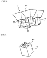
- Fig. 4 is a perspective view of a dual linear polarization horn array antenna according to another embodiment of the present invention
- Fig. 5 is a transparent view of a dual linear polarization horn array antenna shown in Fig. 4 .
- a cross rib 401 is disposed at the upper portion of a horn 10, thereby forming four small aperture sides at the upper portion of the horn 10.
- the horn array antenna shown in Fig. 5 includes a horn shown in Fig. 22 , it is obvious to those skilled in the art that the horn array antenna may include a horn shown in Fig. 19 or any other horn.
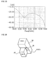
- Fig. 6 is the perspective of a horn array antenna having a horn 10 shown in Fig. 5 according to an embodiment of the present invention. It also shows sixteen apertures are formed in one antenna unit.
- Fig. 8 is a perspective view of a horn area of a horn array antenna as shown in Fig. 2 (tilted from top).
- Fig. 9 is a plane view of a horn;
- Figs. 10 and 12 are sectional perspective views, and
- Fig. 11 is a front perspective view of the horn.
- the horn 10 includes a inclined section 15 formed in a quadrangular pyramid for guiding radio waves for the first polarization and the second polarization, perpendicular to each other, to input into an incident plane thereof, and a polarization filtering unit 20 formed at one end of the inclined section 15.
- the inclined section 15 is tapered in a propagation direction of a radio wave.
- the inclined section 15 has both ends opened along the propagation direction of a radio wave, thereby forming both external and internal apertures.
- the internal aperture is formed at a narrower end of the inclined section 15, in a rectangular shape, and a ledge 17 is formed around the internal aperture, which is projected from the internal aperture toward the center area thereof. As shown in Fig. 9 , the ledge 17 is projected along the internal aperture to have a predetermined width, forming a rectangular aperture.
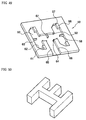
- Fig. 13 is a perspective view of a horn according to another embodiment of the present invention.
- Fig. 14 is a plane view of a horn shown in Fig. 13 .
- Fig. 15 is a side view of a horn shown in Fig. 13 .
- Fig. 16 is a sectional perspective view of a horn shown in Fig. 13 , and
- Fig. 17 is a side cross sectional view of a horn as shown in Fig. 13 .
- a horn 10 includes at least one of ledges 18a and 18b disposed at a tapered portion thereof, and a cross rib 401 forming four apertures. Also, a ledge 19 is formed on one side of the polarization filtering unit 20, thereby improving a parameter S11 of a vertical polarization.
- the horn 10 contains two ledge 18a,18b,19 and a cross rib 401 for forming four apertures.
- the horn 10 is not limited thereto. The number of ledges 18a,18b,19 and apertures can change.
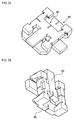
- Fig. 18 is a perspective view of a horn according to another embodiment of the invention.
- the horn holds at least one ledges 18a,18b disposed at a tapered portion and a cross rib 401 for forming four apertures.
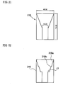
- Fig. 19 shows a schematic cross-sectional view of a horn according to the present embodiment.
- Fig. 20 is the side cross-sectional view of a horn having the same-sized external aperture and the same length of horn as shown in Fig. 19 .
- Fig. 21 is also a schematic side cross-sectional view of a horn having the same performance.
- the length of the horn 110 shown in Fig. 20 and the horn 10 of present embodiment are each about 61.0 mm, and the length of the horn 210 shown in Fig. 21 is about 71.0 mm.
- the widths of the external apertures of each horn 10,110,210 are about 48.0 mm.
- Table 1 shows results of comparing antenna gains of three horns 10,110,210 under conditions of the center frequency of 11.7GHz; the upper sideband of 12.75GHz, the lower sideband of 10.7GH among a satellite broadcasting band KU band from about 10.7GHz to about 12.75GHz.
- Table 1 present embodiment Fig. 20 Fig. 21 10.7GHz 14.8[dBi] 14.3[dBi] 14.8[dBi] 11.7GHz 15.8[dBi] 15.1[dBi] 15.8[dBi] 12.7GHz 16.1[dBi] 15.6[dBi] 16.1[dBi]
- the horn 10 according to the present embodiment and the horn 210 shown in Fig. 21 provide the same performance at all frequency bands.
- the horn having the same-sized external apertures and the same length horns 10 provide a smaller antenna gain than the horn 110 of Fig. 20 as much as about 0.5dBi at 10.7 GHz band, 0,7dBi at 11.7 GHz band, and 0.5dBi at 12.7GHz band.
- the antenna performance will improve at 33% in general. Therefore, the performance of the horn 10 is improved at about 18% compared with that of the conventional horn.
- the height also is reduced by 10 mm compared with a conventional horn having the same performance.
- Fig. 22 is a schematic side cross-sectional view of a horn according to yet another embodiment.
- a pair of ledges '318a and 318b' is formed at the tapered portion of inside horn 310. With at least one of ledges '318a or 318b' formed, the height of the horn antenna can be reduced while sustaining the performance of a horn antenna.
- the length and the size of a horn as of Fig. 22 may differ from those of the horn in Fig. 19 .
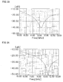
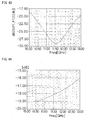
- Fig. 23 is a graph showing a parameter S11 of the horn shown in Fig. 19 ;
- Fig. 24 is another graph showing a parameter S11 of the horn shown in Fig. 20 , and
- Fig. 25 is still another showing a parameter S11 of the horn shown in Fig. 21 .
- the parameter S11 shows a tendency that a radio wave returns to an antenna after the radio wave is radiated from the antenna.
- the parameter S11 is allowable when the parameter S11 is lower than -10 dB.
- the parameter S11 of the horn 10 is in good condition.
- the horn 10 provides the better parameter S11 than the horn shown in Fig. 20 , which provides about -50dB of parameter S11 at 12.2GHz, or not worse than the horn shown in Fig. 21 providing about-30dB of S11 parameter.
- the length of the horn 15 can be shortened not only while sustaining the width of the internal aperture and the width of the external aperture but also while not reducing the gain of the antenna 1.
- the second polarization passes the area of a step difference 25 in the polarization filtering unit 20, thereby guiding to the second polarization guide 50.
- Fig. 26 is a magnified perspective view of the polarization-filtering unit shown in Fig. 2 .
- the polarization filtering unit 20 includes a first port 1 connected to the horn 10; a second port 2 connected to the first polarization guide 30; and a third port 3 connected to the second polarization guide 50.
- the polarization filtering unit 20 extends from the internal aperture to the second polarization guide 50, and has one side with a plurality of steps 25 formed at a predetermined region thereon from the internal aperture.
- the region of the steps 25 makes the width of the filtering unit to be gradually narrower.
- the region of steps 25 separate the first and the second polarization passing the polarization-filtering unit 20 providing the first polarization to the first polarization guide 30 and the second to the second polarization guide 50.
- the first polarization with an electric field direction identical to the 'wider width' of the polarization filtering unit 20, is given to the first polarization guide 30, and the second polarization, with an electric field direction identical to the 'narrow width' of the polarization filtering unit 20, is given to the second polarization guide 50 along the polarization-filtering unit 20.
- the number, the size, and the length of the step differences 25 may change according to the frequency of the second polarization guided along the second polarization guide 50.
- a passage 27, to be connected to the first polarization guide 30, is formed at the central area of the stepped region 25, gradually widening toward the first polarization 30 along the direction of length.
- the width, the length, and the height of the step difference, forming the passage 27, may change according to the frequency of the first polarization provided to the first polarization guide 30.
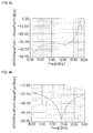
- Figs. 27 to 29 are graphs showing S parameters of the first polarization of a polarization-filtering unit as in Fig. 26 .
- Fig. 27 shows the S11 parameter of a first port 1;
- Fig. 28 shows the S21 parameter between the first port 1 and the second port 2; and
- Fig. 29 shows the S31 parameter between the first port 1 and the third port 3.
- the first polarization has about - 24 dB of the S11 parameter at 10.7GHz, and has the high S21 parameter identical to the S11 at the same frequency band. That is, according to the graphs, the first polarization inputs through the first port, and outputs through the second port.
- Figs. 30 to 32 are graphs showing S parameters of the second polarization of a polarization-filtering unit shown in Fig. 26 .
- Fig. 30 shows the S11 parameter of a first port 1
- Fig. 31 shows the S21 parameter between a first port 1 and a second port 2
- Fig. 29 the S31 parameter between the first port 1 and the third port 3.
- the second polarization has the S11 parameter gradually decreasing as the frequency band increases, and that the S11 parameter of the second polarization lessens to more than -10 dB throughout the region of the satellite broadcasting.
- the S31 parameter increases. That is, the second polarization inputs from the first port and outputs through the third port.
- Fig. 33 is a perspective view of a first polarization guide shown in Fig. 2
- Fig. 34 is a transparent view of a first polarization guide of Fig. 33
- Fig. 35 is the plane view of a first polarization guide of Fig. 33
- Fig. 36 is the side view of a first polarization guide shown in Fig. 33
- Fig. 37 is a perspective view of a first polarization guide connected to a polarization-filtering unit
- Fig. 38 is a transparent perspective view of a second waveguide and a second connecting pipe.
- the first polarization guide 30 guides the first polarization inputted through the four horns 10, and outputs the first polarization to a first main aperture 46.
- the first polarization guide 30 has four apertures A, B, C, and D connected to the four polarization-filtering units 20,
- the first polarization guide 30 includes a first waveguide 35 with a pair of apertures, and a second waveguide 40 with a pair of apertures arranged in parallel with the first waveguide 35. It also has a first mixing pipe 45 connected to the first waveguide 35 and the second waveguide 40 outputting the first polarization.
- Apertures are formed at both ends of the first waveguide 35 and the second waveguide 40, each of them connected to the passage 27 of the polarization-filtering unit 30.
- the first polarization guide 30 is connected to the four polarization-filtering units 20 for receiving the first polarization inputting through the four inclined sections 15.
- the first waveguide 35 includes a first ledge 36 and a first horizontal layer 37.
- the first ledge 36 is formed at the central area along the length direction, and the first horizontal layer 37 is formed for mixing the first polarizations inputted from both apertures.
- the first ledge 36 formed at the upper area of the first waveguide 35, has a rectangular parallel-piped shape along the length direction of the first waveguide 35.
- the first polarization inputted to the first waveguide 35, according to Fig. 36 has horizontal directivity components of aperture, making the first ledge 35 change the propagation direction of the first polarization inputting the first connecting pipe 48 to have up and down directivity components.
- the first horizontal layer 37 is upwardly projected from a corresponding location of the bottom side of the first waveguide 35, extending to the bottom of the first ledge 36.
- the width of the first horizontal layer 37 is identical to the width of the aperture, and the thickness thereof is thinner than a predetermined thickness.
- the first polarizations inputting through both the apertures reach the first horizontal layer 37, mixed with each other, changing the propagation direction thereof by the first ledge 36, and propagating toward the first mixing pipe 45.
- the second waveguide 40 is formed in a shape of the first waveguide 35, turned upside down.
- the second waveguide 40 includes a second ledge 41 formed at a central area thereof and a second horizontal layer 42 for mixing the first polarizations inputted through both apertures.
- the second ledge 41 is formed at the bottom area of the second waveguide 40
- the second horizontal layer 42 is formed at the upper area of the second waveguide 40.
- the first polarization inputting to the second waveguide 40 is mixed at the second horizontal layer 42, formed at the upper portion of the second waveguide 40, changing the propagation direction thereof by the second ledge 41 and propagating to the first mixing pipe 45.
- the thickness and length of the first and second horizontal layers 37 and 42 as well as the thickness and length of the first and second ledges 36, and 41 is decided according to the frequency of the first polarization inputting to the first waveguide 35 and the second waveguide 40.
- the first mixing pipe 45 has a first connecting pipe 48 connected to the first waveguide 35, a second connecting pipe 49 connected to the second waveguide 40, and a first main aperture 46 for outputting the first polarization from the first and second connecting pipes 48 and 49.
- the first connecting pipe 48 is connected to the upper portion of the central area of the first waveguide 35, extending in parallel with the first waveguide 35 and bending downwardly to a third horizontal layer 47 of the first mixing pipe 45 at a predetermined angle.
- the second connecting pipe 49 connected to the bottom of the central area of the second waveguide 40, extends in parallel with the second waveguide 40, and bends upwardly toward the third horizontal layer 47 of the first mixing pipe 45 at a predetermined angle.
- the first mixing pipe 45 is formed in the horizontal direction, which is the length direction of the first and the second connecting pipes 48 and 49.
- the third horizontal layer 47 is projected along the length direction of the first mixing pipe 45 at one end adjacent to the first and second connecting pipes 48 and 49.
- a pair of fifth ledges 44 is internally projected from both walls of the first mixing pipe 45 at a predetermined area thereof along the length direction of the first mixing pipe 45 to reduce the width of the first mixing pipe 45.
- the center frequency of a signal inputted to the first mixing pipe 45 is decided.
- the center frequency of a signal inputted to the first mixing pipe 45 can be shifted.
- the performance of the first mixing pipe 45 depends on the presence or the non-presence of the pair of fifth ledges 44.
- a mixing pipe according to an embodiment of the present invention will be described with reference to Fig. 39 to 42 .
- a PORT 2-3 passage between a second port 2 to a third port 3 denotes a passage formed between the second port 2 and the third port 3 which face one another
- a PORT 1 passage denotes a passage formed between the first port 1 to the junction of the PORT 2-3 passage, as shown in Figs. 39, 40 and 41 .
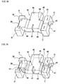
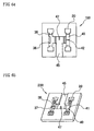
- Fig. 39 is a perspective view of a first mixing pipe according to the embodiment of the present invention
- Fig. 40 is a perspective view of a first mixing pipe with the fifth ledge removed.
- a pair of fifth ledges 44 is projected to the inside of the first mixing pipe 45 from a predetermined area along the length direction of the PORT 1 passage in order to reduce the left-right width of the port 1 passage of the first mixing pipe 45, which is the width of the longer side of the PORT 1 passage of Fig. 39 .
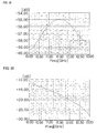
- Fig. 43 is a graph showing the S11 parameter of the first mixing pipe of Fig. 39
- Fig. 44 is a graph showing the S11 parameter of the first mixing pipe of Fig. 40 .
- a side connected to the first connecting pipe 48 and another side connected to the second connecting pipe 49 are defined as a second port and a third port
- a first port is defined as the first main aperture 46.
- the first mixing pipe 45 has about-29dB of S11 parameter at 11.75GHz. It denotes that the amount of reflecting a radio wave outputted or inputted through the first port 1 is less.
- the first mixing pipe with a pair of fifth ledges 44 removed has about -18dB of the S11 parameter at the same frequency band. It denotes that the fifth ledges improve the performance of the first mixing pipe 45.
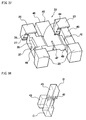
- Fig. 41 is a schematic perspective view of a mixing pipe according to another embodiment of the present invention
- Fig. 42 is a schematic perspective view of a mixing pipe according to still another embodiment of the present invention
- Fig. 45 and Fig. 46 are graphs showing S11 parameter of Fig. 41 , and S11 parameter of Fig. 45 .
- Fig. 41 shows a pair of sixth ledges 51 projected from a predetermined area to the inside of the mixing pipe along the length direction of the PORT 1 passage, and that the pair is formed to reduce the width of the up-down side of the mixing pipe, that is, the width of the short side of the PORT 1 passage shown in Fig. 41 .
- a pair of grooves 52 is also formed in the length direction of the PORT 2-3 passage, especially showing that it is externally concaved to be adjacent to the horizontal layer 47.
- the mixing pipe of Fig. 41 according to an embodiment of the present invention has about -32 dB of the S11 parameter at 11.75GHz.
- seventh ledges 54a and 54b are formed at predetermined areas of the PORT 2-3 passage. More clearly, the seventh ledge 54a is projected from a predetermined area to the inside of the mixing pipe especially, in a direction that reduces the short direction of the PORT 2-3 passage. Whereas, the seventh ledge 54b is formed to be projected from an area adjacent to the junction of the PORT 1 passage including the PORT 2-3 passages into the inside of the mixing pipe. The seventh ledge 54b formed in that direction reduces the short side direction of the PORT 2-3 passage.
- the mixing pipe divides radio wave inputted from one port, i.e., the first port 1, into two ports, i.e., the second and third ports 2 and 3, or gathers radio waves inputted from two ports, i.e., the second and third ports 2 and 3, to one port, i.e., the first port 1. Therefore, the mixing pipe shown in Figs. 39 , 41, and 42 is used as a function that receives two radio waves and gathers the received radio waves, or receives one radio waves and divides the received radio wave into two radio waves.
- Figs. 47 and 48 are perspective views of a second polarization guide 50 shown in Fig. 2
- Fig. 49 is a cross-sectional perspective view of a second polarization guide 50 of Fig. 2
- Fig. 50 is a perspective view of a second polarization guide 50 according to the related art.
- the second polarization guide 50 is disposed in parallel with the first polarization guide 30.
- the second polarization guide 50 receives the second polarization received through the polarization filtering unit 20 and outputs the received second polarization.
- the second polarization guide 50 includes a third waveguide 55 changing the propagation direction of the second polarization, a fourth waveguide 60 disposed in parallel with the third waveguide 55, and a second mixing pipe 65 having a second main aperture connected to the third and fourth waveguides 55 and 60 for outputting the second polarization.
- the second and fourth waveguides 55 and 60 have both ends upwardly opened and connected to the polarization-filtering unit 20.
- the third and fourth waveguides 55 and 60 are disposed both perpendicularly from the first and second waveguides 35 and 40 and in a direction to connect the first waveguide 35 and the second waveguide 40.
- a third ledge 56 is formed at both ends of the third waveguide 55 where it communicates with the polarization-filtering unit 20.
- the third ledge 56 is formed in a rectangular parallel-piped shape along the length direction of the third waveguide 55, and projected upwardly from the bottom side of the third waveguide 55.
- the second polarization with the electric field direction along the narrow width of the polarization-filtering unit 20 reaches the third ledge 56, thereby changing the propagation direction.
- a side facing the third ledge 56 is formed of a reflecting side 57 inclined at a predetermined angle. After the second polarization changes the propagation direction thereof at the third ledge 56, the second polarization is reflected by the reflecting side 57.
- a fourth horizontal layer 58 extends from the central area of the third waveguide 55 in a horizontal direction of a length direction toward the second mixing pipe 65 as much as the predetermined width.
- the second polarizations reflected from the reflecting sides 57 at both ends of the third waveguide 55 are mixed at the fourth horizontal layer 58 and propagated to the second mixing pipe 65.
- the fourth waveguide 60 is formed in a shape identical to the third waveguide 55. That is, a fourth ledge 61 is formed at both ends of the fourth waveguide 60 where it communicates with the polarization-filtering unit 20. A reflecting side 62 is formed at a side facing the fourth ledge 61 of the fourth waveguide 60. A fifth horizontal layer 63 extends from the central area of the fourth waveguide 60 in perpendicular to the length direction of the fourth waveguide 60 as much as a predetermined width.
- a second polarization inputting to the fourth waveguide 60 changes the propagation direction thereof by the fourth ledge 61, and reflects from the reflecting side 62, thereby propagating to the fifth horizontal layer 63.
- the frequency of the second polarization inputted and outputted to/from the second polarization guide 50 can be controlled on the thickness and length of the fourth and fifth horizontal layers 58 and 63, and on the width and height of the reflecting sides 57 and 62.
- Figs. 51 and 52 are perspective views of a first polarization guide connected with a second polarization guide from different angles.
- the first polarization guide is vertically coupled to the second polarization guide.
- Fig. 53 is a perspective view of third and fourth waveguides connected with a polarization filtering unit.
- the polarization-filtering unit 20 is formed in a rectangular passage, and the second polarization is formed in an electric field direction along a narrow width of the polarization-filtering unit 20.
- the cross-sections of the third and fourth waveguides 55 and 60 connected to the polarization filtering unit 20 are formed in a narrow rectangular shape. Accordingly, the second polarization shifts the electric direction into top and bottom directions when the second polarization meets the third and the fourth ledges 56, and 61.
- the propagation direction usually changes at 90°. Therefore, the part shown in Fig. 53 is called a radio wave bending unit.
- the second mixing pipe 65 is formed between the third waveguide 55 and the fourth waveguide 60 parallel to the third and fourth waveguides 55 and 60, and the second mixing pipe 65 is disposed at the right angle to the first mixing pipe 45.
- a second main aperture 66 therefore, formed at one end of the second mixing pipe 65 is at the right angle to the first main aperture 46.
- a sixth horizontal layer 67 is formed at one end facing the second main aperture 66 of the second mixing pipe 65, projecting along the length direction of the third and fourth waveguides 55 and 60. The second polarizations from the third and fourth waveguides 55 and 60 get mixed at the sixth horizontal layer 67, and the mixed second polarization propagates toward the second main aperture 66.
- the second mixing pipe 65 can change the frequency band of an inputting and outputting signal according to the length and thickness of the sixth horizontal layer 67 and a pair of ledges 64. Since the second polarization guide 50 includes the ledge 53, the antenna performance can be improved as shown in S11 parameter of Fig. 43 .
- the conventional second polarization guide has a narrow horizontal width compared to the height thereof.
- the conventional second polarization guide is formed to comparatively have a higher height.
- the second polarization guide 50 according to the present embodiment shown in Fig. 47 has a lower height compared to a horizontal width.
- the second polarization guide 50 according to the present embodiment has 50% of the height of the conventional second polarization guide. Therefore, the height of the second polarization guide 50 can be reduced, and the overall size of the antenna 1 can be miniaturized.
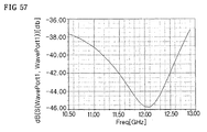
- Fig. 54 shows radio wave bending units that change propagation direction of magnetic field and electric field at 90° according to another embodiment of the present invention.
- Fig. 55 is a diagram for describing a radio wave bending unit of Fig. 54
- Fig. 57 is the graphical representation showing S11 parameter of Fig. 54 .
- the radio wave bending unit as shown Fig. 54 can be used at the junction area of both ends of the third and fourth waveguides 55 and 60 and the polarization-filtering unit 20.
- the unit can also be used to change the magnetic field and the electric field at 90°.
- the radio wave bending unit has good S11 parameter.
- the structures shown in Fig. 55 and 56 can change the electric field at 90° and the magnetic field at 90° respectively, according to the present embodiment.
- the horn 10 When the horn 10 receives the radio wave, it guides the radio wave along the inclined section 14, through the ledge 17, and to the polarization-filtering unit 20. Then, the plurality of step differences 25 gradually narrows the one side of the polarization-filtering unit 20. Therefore, the first polarization having an electric field direction identical to the long width of the polarization filtering unit 20 cannot pass through the polarization filtering unit 20, thereby propagating to the first polarization guide 30 through an aperture facing the first polarization guide 30 of the polarization filtering unit 20.
- the second polarization having an electric field direction identical to the short width of the polarization filtering unit 20 downwardly propagates along the polarization filtering unit 20, inputting to the second polarization guide 50.
- the first polarization inputs to each aperture of the first and second waveguides 35, and 40 of the first polarization guide 30 In the first waveguide 35, the first polarizations input through each aperture reach the first horizontal layer 37 and get mixed together. Then, the electric field direction of the first polarizations changes to the up and down direction at the first ledge 36. In the second waveguide 40, the first polarizations input through each aperture are mixed together at the second horizontal layer 42. The electric field direction thereof changes to an up and down direction at the second ledge 41.
- the first polarizations from the first and second waveguides 35 and 40 propagate along the first and second connecting pipes 48 and 49, and enter the first mixing pipe 45. In the first mixing pipe 45, the first polarizations from the first and second waveguides 35 and 40 mix at the third horizontal layer 47 and reenter the first main aperture.
- the second polarization guided to the second polarization guide 50 through the polarization filtering unit 20 holds an electric field direction identical to a short width of the polarization filtering unit 20.
- the propagation direction of the second polarization changes by the third and fourth ledges 56 and 61 formed at the third and fourth waveguides 55 and 60.
- the second polarizations reflected from the reflecting sides 57 and 62 of the third and fourth waveguides 55 and 60 propagate to the fourth and fifth horizontal layers 58 and 63 resulting in the mixing together at the fourth and fifth horizontal layers 58 and 63.
- the mixed second polarization propagates to the second mixing pipe 65.
- On the sixth horizontal layer 67 of the second mixing pipe 65 the second polarizations from the third and fourth waveguides 55 and 60 mix together, and the mixed the second polarization consequentially enter through the second main aperture 66 of the second mixing pipe 65.
- the second polarization input to the second mixing pipe 65 through the second main aperture 66 is separated at the sixth horizontal layer 67 and guided to the third and fourth waveguides 55 and 60.
- the second polarization is separated again by the fourth and fifth horizontal layers 58 and 63.
- the separated polarizations are then reflected from the reflecting sides 57 and 62, and provided to the third and fourth ledges 56 and 61.
- the second polarization changes the propagation direction to the polarization filtering unit 20 with the help of the third and fourth ledges 56 and 61 elevating to the polarization-filtering unit 20.
- the first polarization input to the first mixing pipe 45 through the first main aperture 46 is separated at the third horizontal layer 47, and the separated first polarizations are transferred to the first and second waveguides 35 and 40 through the first and second connecting pipes 48 and 49.
- the propagation direction of the first polarization changes at the first and second ledges 36 and 41, and the first polarization propagates to each aperture by the first and second horizontal layers 37 and 42.
- the first polarizations so outputted to the each polarization filtering unit 20 through each aperture are mixed with the second polarization from the second polarization guide 50, and the mixed polarization is radiated to the space through the inclined section 15.
- a configuration for manufacturing the dual linear polarization horn array antenna 1 according to the present embodiment will be described in an antenna unit.
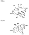
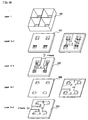
- Fig. 58 is an exploded perspective view of each layer of a dual linear polarization horn array antenna according to an embodiment of the present invention.
- Fig. 59 is a perspective view of the first layer of dual linear polarization horn array antenna according to an embodiment of the present invention
- Fig. 60 is a plan view of a first layer shown in Fig. 58 .
- Fig. 61 is a rear view of a first layer shown in Fig. 58 .
- the dual linear polarization horn array antenna includes a first layer 100, a first intermediate layer 150, a second layer 200, a second intermediate layer 250, and a third layer 300.
- a inclined section 15 of a horn 10 and a ledge 17 are formed in the first layer 100. Accordingly, the inclined section 15 is formed at the front side of the first layer 100, and the internal aperture is formed at the rear side of the first layer 100.
- Fig. 62 is a perspective view of a first intermediate layer shown in Fig. 58 ;
- Fig. 63 is a plane view of a first intermediate layer shown in Fig. 58 ;
- Fig. 64 is a rear view of a first intermediate layer shown in Fig. 58 .
- the rear side of the first intermediate layer 150 includes the upper portion of the first and second waveguides 35 and 40 of the first polarization guide 30, and the upper portion of the first mixing pipe 45.
- Fig. 65 is a perspective view of a second layer shown in Fig. 58 ;
- Fig. 66 is a plan view of a second layer shown in Fig. 58 ;
- Fig. 67 is a rear view of a second layer shown in Fig. 58 .
- the second layer 200 includes a lower area of the first polarization guide 30 and the polarization filtering unit 20. That is, the second layer 200 includes the first horizontal layer 37 of the first waveguide 35, the second ledge 41 of the second waveguide 40, and the remained portion of the third horizontal layer 47 of the first mixing pipe 45.
- the polarization filtering unit 20 is formed at each aperture of the first and second waveguides 35 and 40 of the first polarization guide 30 to penetrate the second layer 200. Accordingly, the polarization filtering unit 20 is only formed at the rear side of the second layer 20.
- Fig. 68 is a perspective view of a second intermediate layer shown in Fig. 58
- Fig. 69 is a rear view of a second intermediate layer shown in Fig. 58 .
- the polarization filtering unit 20 is formed at the second intermediate layer 250 to penetrate therethrough, as well as a predetermined upper portion of the second polarization guide 50 at the rear side of the second intermediate layer 250.
- the fourth and fifth horizontal layers 58 and 63 of the third and fourth waveguides 55 and 60, and the sixth horizontal layer 67 of the second mixing pipe 65 are formed at the rear side of the second intermediate layer 250.
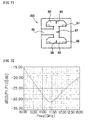
- Fig. 70 is a perspective view of a third layer
- Fig. 71 is a plan view of a third layer.
- the lower portion of the second polarization guide 50 is formed at the third layer 300.
- the third layer 300 forms the second polarization guide 50 with the second intermediate layer 250 and includes the third and fourth waveguides 55 and 60, and the second mixing pipe 65 as well.
- the third layer 300 further includes the fourth and fifth horizontal layers 58 and 63, along with the sixth horizontal layer 67, and the third and fourth ledges 56 and 61.
- the horn array antenna according to the present embodiment was described based on an antenna unit formed with four horns. With an antenna gain that stands higher than 27 dB, it is preferably assumed that the horn array antenna has an enhanced output. Popular approval goes with the antenna that has greater gain than 31dB.
- a horn array antenna is designed to have one antenna unit with four separate antenna units in vertical direction and in horizontal directions, ultimately forming one set of 16 antenna units.
- the upper area should likely have 390 mm x 390 mm, and the height at 61mm.
- Table 2 shows the antenna gain of a horn array antenna formed of one antenna unit according to an embodiment of the present invention.
- Table 2 10.7GHz 11.7GHz 12.7GHz First polarization 20.6dBi 21.3dBi 21.4dBi Second polarization 20.5dBi 21.2dBi 21.3dBi
- the antenna gain of the first polarization guide 30 is obtained when the radio wave inputs through the first main aperture 46 and outputs through the inclined section 15.
- the horn array antenna according to the present embodiment has a gain higher than 20 dBi at each frequency band of satellite broadcasting.
- the antenna gain of the second polarization guide 50 is a gain obtained when the radio wave inputs through the second main aperture 66 and outputs through the inclined section 15.
- the horn antenna has a gain of higher than 20 dBi at each frequency band of satellite broadcasting.
- Table 3 shows the antenna gains of a horn array antenna formed of 16 antenna units.
- Table 3 10.7GHz 11.7GHz 12.7GHz First polarization 33.0dBi 33.7dBi 34.0dBi Second polarization 33.0dBi 33.6dBi 33.9dBi
- the antenna gain of the first polarization guide 30 is higher than 33dBi at each frequency band of satellite broadcasting, and gain of the second polarization guide 50 is higher than 33dBi at each frequency band of satellite broadcasting.
- the horn array antenna formed of antenna units on the present embodiment of invention has the superior antenna performance.
- Fig. 72 is a graphical view of the S11 parameter of a dual linear polarization horn array antenna according to an embodiment of the present invention.
- the S11 parameter graph of the horn 10 shows the operating frequency formed around the center frequency of 11.4GHz.
- the operating frequency having the S11 parameter of about -10 dB also appears in a range from 10 GHz to 13 GHz.
- the dual linear polarization horn array antenna 1 is operated within a frequency band range 10.7GHz to 12.75GHz, which are the existing frequency band of the satellite broadcasting.
- the dual linear polarization horn array antenna 1 based on the present embodiment has superior performance.
- the height of the horn 10 can be reduced while sustaining the antenna efficiency by forming the ledges 17 at the horn 10.
- the height of the second polarization guide 50 can also be reduced by the horizontal width of the second polarization guide 50 to be wider than the height thereof.
- the overall size of the dual linear polarization horn array antenna 1 can be reduced. Although it is reduced in size, the dual linear polarization horn array antenna 1 is compact and has an improved antenna performance as FIGd in Table 3.
- first and second polarizations were described based on electric field, they can be applied to magnetic field.
- the configurations for manufacturing the horn 10, the first polarization guide 30, and the second polarization guide 50 shown in Figs. 20 to 58 are only examples of the present invention. According to needs, at least two of the horn 10, the first polarization guide 30, and the second polarization guide 50 can be manufactured at once through injection molding.
- the manufacturing of the horn 10, the first polarization guide 30, and the second polarization guide 50 is not limited to the number of layers illustrated in Figs. 58 to 71 .
- the performance of the antenna can be improved while the size of the antenna is reduced.
Abstract
Description
- The present invention relates to a horn array antenna for dual linear polarization; more particularly, to a horn array antenna for dual linear polarization for improving the antenna performance and reducing the size of antenna.
- Waves traveling higher than ultrahigh frequency have very short wavelengths and have characteristics similar to light. In order to effectively transmit or receive such waves, the technology has advanced itself to improve the directivity, applying optics theory or the theory that says a megaphone concentrates a sound wave. Such antennas, with enhanced directivity, are being manufactured in various shapes and configurations; they are known as horn antenna, parabola antenna, lens antenna, and slot antenna which have waveguides with holes formed thereon. And the use of these antennas has now become wide.
- Among these, the horn antenna is formed of a waveguide with one end formed in a horn shape and opened at both ends. The horn antenna radiates radio waves by vibrating one end of the waveguide and propagating radio waves along the waveguide. As the impedance between the waveguide and the air is not matching, it reflects a part of the radio wave, which means that the entire energy is not radiated through air. Therefore, a horn antenna is designed to have its waveguide aperture to be gradually wider so that it matches the impedance between the air and the waveguide and allows it to maximally radiate energy through the aperture.
-
Fig. 1 is the cross-sectional view of a horn in a horn antenna according to the related art. - In
Fig. 1 , the horn antenna shows anexternal aperture 2 facing the air, and an internal aperture 3 at a side where the vibration starts. In such an antenna, the size of the external aperture 3 decides the performance. The wider the size of the external aperture 3 is, the better the performance is provided. A ratio (S2/S1) of the size of theexternal aperture 2 and that of the internal aperture 3 influences the performance of the antenna. In other words, the difference between theexternal aperture 2, the internal aperture 3, and the gradient are important factors that decide the performance. So an antenna designed to perform better and to have a long horn usually has a larger size. - The present trend of the development of communication technology is towards compactness, and accordingly the demand persists that technology develop a method to reduce the size of an antenna while sustaining its performance.
- It is, therefore, an aspect of the present invention to provide a horn array antenna with dual linear polarization having an improved antenna performance and a small size.
- Other objects and advantages of the present invention can be understood by the following description, which become apparent on reference to the embodiments of the present invention. To those skilled in the art, it is obvious to which the present invention pertains and how the objects and advantages measure up as claimed, and by means of combinations.
- In accordance with one aspect of the present invention, there is provided a horn array antenna for dual linear polarization includes a horn, a first polarization guide, and a second polarization guide. The horn guides inputting and outputting radio waves, and includes a inclined section tapered along a propagation direction of a radio wave and having an internal aperture formed at one end having a narrower width and at least one of ledges projected at the end toward an inside of the internal aperture. The first polarization guide is connected to the horn and guides a first polarization. The second polarization guide is connected to the horn, disposed in parallel with the first polarization guide, and guides a second polarization having directivity perpendicular to the first polarization.
- The horn may include: a inclined section formed to be tapered; and a polarization filtering unit connecting the aperture having the ledge of the inclined section with the first polarization guide.
- A plurality of steps may be formed at one side of the polarization filtering unit so that the width of the polarization filtering unit is gradually narrowed in a direction to the first polarization guide and an aperture may be formed at the region of the plurality of steps to connect with the first polarization guide.
- The ledge may be formed along a circumference of the aperture, and a shape of the ledge may be decided by a width of the ledge projected toward the aperture.
- The shape of the aperture may be a square.
- The first polarization guide may include: a first waveguide having a pair of apertures connected to a pair of the horns; a second waveguide having a pair of apertures connected to other pair of the horns, and disposed in parallel with the first waveguide; and a first mixing pipe disposed between the first waveguide and the second waveguide, connecting the first waveguide and the second waveguide, and having a first main aperture for inputting and outputting a first polarization.
- Each aperture of the first waveguide may be connected to a pair of the polarization filtering units, a first ledge may be downwardly projected from a upper area of a central area of the first waveguide for changing a propagation direction of the first polarization, and a first horizontal layer may be upwardly projected from a lower area of the first ledge for separating or mixing the first polarization.
- Each aperture of the second waveguide may be connected to the other pair of the polarization filtering units, a second ledge may be upwardly projected from a lower area of a central area of the second waveguide for changing a propagation direction of the second polarization, and a second horizontal layer may be downwardly projected at an upper area of the second ledge for separating and mixing the first polarization.
- The first and second ledge may be formed long in a length direction of the first and second waveguides, and formed in a rectangular parallelepiped shape projected toward the inside of the first and second waveguides.
- The first and second horizontal layers may be formed to have a width corresponding to a horizontal width of the first and second waveguides and to have a thickness thinner than a predetermined thickness.
- The first mixing pipe may include: a first main aperture for inputting and outputting a first polarization; a first connecting pipe connected to the first waveguide; and a second connecting pipe connected to the second waveguide.
- The first connecting pipe may be connected to an upper area of a central area of the first waveguide, and may be downwardly bended toward the first mixing pipe at a predetermined angle.
- The second connecting pipe may be connected to a lower area of a central area of the second waveguide, and may be upwardly bended to the first mixing pipe at a predetermined angle.
- A third horizontal layer may be projected in a perpendicular direction of a length direction of the first and second connecting pipe between the first and second connecting pipes of the first mixing pipe.
- The first mixing pipe may include a fifth ledge projected at a predetermined area along a length direction toward an inside of the first mixing pipe so as to reduce a width of the first mixing pipe.
- The second polarization guide may include: a third waveguide connected to a pair of the polarization filtering units for changing a propagation direction of a second polarization; a fourth waveguide connected to the other pair of the polarization filtering units and disposed in parallel with the third waveguide; and a second mixing pipe connected to the third and fourth waveguides and having a second main aperture for inputting and outputting a second polarization.
- Both ends of the third waveguide may be upwardly opened and connected to the polarization filtering units, and a third ledge may be formed at an area penetrating the polarization filtering unit to change a propagation direction of the second polarization. Both ends of the fourth waveguide may be upwardly opened and connected to the polarization filtering units, and a fourth ledge may be formed at an area penetrating the polarization filtering unit and for changing a propagation direction of the second polarization.
- A fourth horizontal layer may extend from a central area of the third waveguide toward the second mixing pipe as much as a predetermined width. A fifth horizontal layer may extend from a central area of the fourth waveguide toward the second mixing pipe as much as a predetermined width.
- An inclined reflecting side may be formed at a side facing the third ledge in both ends of the third waveguide at a predetermined angle. An inclined reflecting side may be formed at a side facing the fourth ledge in the both end of the fourth waveguide at a predetermined angle.
- A sixth horizontal layer may be projected between the third waveguide and the fourth waveguide of the second mixing pipe along a length direction of the third waveguide and the fourth waveguide.
- A rib may be formed at an upper area of the horn to form at least two apertures at the upper are of the horn.
- A ledge may be formed at an opposite side of the plurality of steps.
- In accordance with another aspect of the present invention, there is provided a horn array antenna for dual linear polarization includes a first layer, a second layer, and a third layer. The first layer includes a plurality of horns therein, where each of the horns guides inputting and outputting radio waves, and has a inclined section tapered along a propagation direction of a radio wave and having an internal aperture formed at one end having a narrower width and at least one of ledges projected at the internal aperture toward an inside of the internal aperture. The second layer has a first polarization guide formed therein, where the first polarization guide is connected to the horn and guides a first polarization, and the third layer includes a second polarization guide formed therein, where the second polarization guide is connected to the horn, disposed in parallel with the first polarization guide, and guides a second polarization having a directivity perpendicular to the first polarization.
- The horn array antenna for dual linear polarization may further include a first intermediate layer disposed between the first layer and the second layer and having a polarization filtering unit for connecting the aperture with the ledge formed and the first polarization guide.
- A width of the polarization filtering unit may be gradually narrowed in a direction to the first polarization guide by a plurality of steps formed at one side of the polarization filtering unit formed at the first intermediate layer. The polarization filtering unit may extend to the second layer so as to be connected to the aperture of the first polarization guide.
- The first polarization guide formed at the second layer may include: a first waveguide having a pair of apertures connected to a pair of the horns; a second waveguide having a pair of aperture connected to the other pair of the horns, and disposed in parallel with the first waveguide; and a first mixing pipe disposed between the first and second waveguides for connecting the first and second waveguides and having a first main aperture for inputting and outputting a first polarization.
- The first horizontal layer of the first waveguide for separating and mixing the first polarization may be formed and a second ledge of the second waveguide for changing a propagation direction of the first polarization may be formed in a side facing the first intermediate layer of the first layer.
- A first ledge of the first waveguide for changing a propagation direction of the first polarization and a second horizontal layer of the second waveguide for separating and mixing the first polarization may be formed in the first intermediate layer.
- A first connecting pipe connecting an upper area of a central area of the first waveguide and the first mixing pipe and downwardly bended to the first mixing pipe at a predetermined angle, and a second connecting pipe connecting an lower area of a central area of the second waveguide and the first mixing pipe and upwardly bended to the first mixing pipe at a predetermined angle are formed at the second layer; and wherein the first mixing pipe is formed at the second layer to be disposed between the first connecting pipe and the second connecting pipe.
- The second polarization guide formed at the third layer may include: a third waveguide connected to a pair of the polarization filtering units and for changing a propagation direction of a second polarization; a fourth waveguide connected to the other pair of the polarization filtering units and disposed in parallel with the third waveguide; and a second mixing pipe connecting the third and fourth waveguides and having a second main aperture for inputting and outputting a second polarization.
- A second intermediate layer having the polarization filtering unit formed therein may be disposed between the second and third layers.
- According to the present invention, the performance of the antenna can be improved while the size of the antenna is reduced.
- The above and other objects and features of the present invention will become apparent from the following description of the preferred embodiments given in conjunction with the accompanying drawings, in which:
-
Fig. 1 is the cross-sectional view of a horn in a horn antenna according to the related art; -
Fig. 2 is the front view of a dual linear polarization horn array antenna; -
Fig. 3 is the side view based onFIG 2 ; -
Fig. 4 is a perspective view of a dual linear polarization horn array antenna according to another embodiment of the present invention; -
Fig. 5 is a transparent view of a dual linear polarization horn array antenna shown inFig. 4 ; -
Fig. 6 is the perspective of a horn array antenna having a horn shown inFig. 5 according to an embodiment of the present invention. -
Fig. 7 is a side cross-sectional view of the horn array antenna; -
Fig. 8 is a perspective view of a horn area of a horn array antenna as shown inFig. 2 (tilted from top); -
Fig. 9 is a plane view of a horn; -
Figs. 10 and12 are sectional perspective views of a horn; -
Fig. 11 is a front perspective view of a horn. -
Fig. 13 is a view of a horn according to another embodiment of the present invention; -
Fig. 14 is a plane view of a horn shown inFig. 13 ; -
Fig. 15 is a side view of a horn shown inFig. 13 ; -
Fig. 16 is a sectional perspective view of a horn shown inFig. 13 ; -
Fig. 17 is a side cross sectional view of a horn as shown inFig. 13 ; -
Fig. 18 is a perspective view of a horn according to another embodiment of the invention; -
Fig. 19 shows a schematic cross-sectional view of a horn according to the present embodiment; -
Fig. 20 is the schematic side cross-sectional view of a horn having the same-sized external aperture and the same length of horn as shown inFig. 19 ; -
Fig. 21 is also a schematic side cross-sectional view of a horn having the same performance as shown inFig. 19 ; -
Fig. 22 is a schematic side cross-sectional view of a horn according to yet another embodiment; -
Fig. 23 is a graph showing a parameter S11 of the horn shown inFig. 19 ; -
Fig. 24 is another graph showing a parameter S11 of the horn shown inFig. 20 ; -
Fig. 25 is still another showing a parameter S11 of the horn shown inFig. 21 ; -
Fig. 26 is a magnified perspective view of the polarization filtering unit ofFig. 2 ; -
Fig. 27 shows the S11 parameter of afirst port 1; -
Fig. 28 shows the S21 parameter between thefirst port 1 and thesecond port 2; -
Fig. 29 shows the S31 parameter between thefirst port 1 and the third port 3; -
Figs. 30 to 32 are graphs showing S parameters of the second polarization of a polarization-filtering unit shown inFig. 26 ; -
Fig. 33 is a perspective view of a first polarization guide shown inFig. 2 ; -
Fig. 34 is a transparent view of a first polarization guide ofFig. 33 ; -
Fig. 35 is the plane view of a first polarization guide ofFig. 33 ; -
Fig. 36 is the side view of a first polarization guide shown inFig. 33 ; -
Fig. 37 is a perspective view of a first polarization guide connected to a polarization-filteringunit 20; -
Fig. 38 is a transparent perspective view of a second waveguide and a second connecting pipe; -
Fig. 39 is a perspective view of a first mixing pipe according to the embodiment of the present invention; -
Fig. 40 is a perspective view of a first mixing pipe with the fifth ledge removed; -
Fig. 41 is a schematic perspective view of a mixing pipe according to another embodiment of the present invention; -
Fig. 42 is a schematic perspective view of a mixing pipe according to still another embodiment of the present invention; -
Fig. 43 is a graph showing the S11 parameter of the first mixing pipe ofFig. 39 ; -
Fig. 44 is a graph showing the S11 parameter of the first mixing pipe ofFig. 40 ; -
Fig. 45 and Fig. 46 are graphs showing S11 parameter ofFig. 41 , and S11 parameter ofFig. 42 ; -
Figs. 47 and 48 are perspective views of a second polarization guide shown inFig. 2 ; -
Fig. 49 is a cross-sectional perspective view of a second polarization guide ofFig. 2 ; -
Fig. 50 is a perspective view of a second polarization according to the related art; -
Figs. 51 and 52 are perspective views of a first polarization guide connected with a second polarization guide according to an embodiment of the present invention; -
Fig. 53 is a perspective view of third and fourth waveguides connected with a polarization filtering unit; -
Fig. 54 shows radio wave bending units that change propagation direction of magnetic field and electric field at 90° according to another embodiment of the present invention; -
Fig. 55 and 56 are diagrams for describing a radio wave bending unit ofFig. 54 ; -
Fig. 57 is the graphical representation showing S11 parameter ofFig. 54 ; -
Fig. 58 is an exploded perspective view of each layer of a dual linear polarization horn array antenna according to an embodiment of the present invention; -
Fig. 59 is a perspective view of the first layer of dual linear polarization horn array antenna according to an embodiment of the present invention; -
Fig. 60 is a plan view of a first layer shown inFig. 58 ; -
Fig. 61 is a rear view of a first layer shown inFig. 58 ; -
Fig. 62 is a perspective view of a first intermediate layer shown inFig. 58 ; -
Fig. 63 is a plane view of a first intermediate layer shown inFig. 58 ; -
Fig. 64 is a rear view of a first intermediate layer shown inFig. 58 ; -
Fig. 65 is a perspective view of a second layer shown inFig. 58 ; -
Fig. 66 is a plan view of a second layer shown inFig. 58 ; -
Fig. 67 is a rear view of a second layer shown inFig. 58 ; -
Fig. 68 is a perspective view of a second intermediate layer shown inFig. 58 ; -
Fig. 69 is a rear view of a second intermediate layer shown inFig. 58 ; -
Fig. 70 is a perspective view of a third layer shown inFig. 58 ; -
Fig. 71 is a plane view of a third layer shown inFig. 58 ; and -
Fig. 72 is a graphical view of the S11 parameter of a dual linear polarization horn array antenna according to an embodiment of the present invention. - Other objects and aspects of the invention become apparent from the following description of the embodiments referring to the drawings, set hereinafter.
- A dual linear polarization horn array antenna according to an embodiment of the present invention performs a function of either receiving or transmitting radio waves. For convenience, the constituent elements of the dual linear polarization horn array antenna will be described based on a radio wave receiving function at first. Afterward, the constituent elements will be described based on a radio wave transmitting function thereof.
- According to one embodiment of the present invention, a first polarization denotes a horizontal polarization 'H,' parallel to the equator of earth, and a second polarization denotes a vertical polarization 'V,' which is perpendicular to the equator of earth.
-
Fig. 2 is the front view of a dual linear polarization horn array antenna;Fig. 3 is the side view based onFIG 2 ; andFig. 7 is a side cross-sectional view of the horn array antenna. - As shown in
Figs. 2 ,3 and7 , the dual linear polarizationhorn array antenna 1 includes a plurality ofhorns 10 for receiving radio waves, afirst polarization guide 30 for guiding first polarization, and asecond polarization guide 50 for guiding second polarization. Four of the plurality ofhorns 10, afirst polarization guide 30, and asecond polarization guide 50 form one antenna unit. Hereinafter, the dual linear polarizationhorn array antenna 1 is described based on an antenna unit. - The four
horns 10 are opened toward a space with thefirst polarization guide 30 disposed under thehorns 10, and thesecond polarization guide 50 disposed under thefirst guide 30. Herein, thehorns 10, the first and the second polarization guides 30 and 50 are spaces for the radio wave to move. The shape of a frame for forming thehorn 10, and the first and second polarization guides 30 and 50 will be described later. -
Fig. 4 is a perspective view of a dual linear polarization horn array antenna according to another embodiment of the present invention, andFig. 5 is a transparent view of a dual linear polarization horn array antenna shown inFig. 4 . - According to
Figs. 4 and5 , across rib 401 is disposed at the upper portion of ahorn 10, thereby forming four small aperture sides at the upper portion of thehorn 10. By dividing the upper portion of thehorn 10 to a plurality of aperture sides, the side lob of an antenna is reduced, and the radiation efficiency increased. - Although the horn array antenna shown in
Fig. 5 includes a horn shown inFig. 22 , it is obvious to those skilled in the art that the horn array antenna may include a horn shown inFig. 19 or any other horn. -
Fig. 6 is the perspective of a horn array antenna having ahorn 10 shown inFig. 5 according to an embodiment of the present invention. It also shows sixteen apertures are formed in one antenna unit. -
Fig. 8 is a perspective view of a horn area of a horn array antenna as shown inFig. 2 (tilted from top).Fig. 9 is a plane view of a horn;Figs. 10 and12 are sectional perspective views, andFig. 11 is a front perspective view of the horn. - The
horn 10 includes ainclined section 15 formed in a quadrangular pyramid for guiding radio waves for the first polarization and the second polarization, perpendicular to each other, to input into an incident plane thereof, and apolarization filtering unit 20 formed at one end of theinclined section 15. - The
inclined section 15 is tapered in a propagation direction of a radio wave. Theinclined section 15 has both ends opened along the propagation direction of a radio wave, thereby forming both external and internal apertures. The internal aperture is formed at a narrower end of theinclined section 15, in a rectangular shape, and aledge 17 is formed around the internal aperture, which is projected from the internal aperture toward the center area thereof. As shown inFig. 9 , theledge 17 is projected along the internal aperture to have a predetermined width, forming a rectangular aperture. -
Fig. 13 is a perspective view of a horn according to another embodiment of the present invention.Fig. 14 is a plane view of a horn shown inFig. 13 .Fig. 15 is a side view of a horn shown inFig. 13 .Fig. 16 is a sectional perspective view of a horn shown inFig. 13 , andFig. 17 is a side cross sectional view of a horn as shown inFig. 13 . - Referring to
Figs. 13 to 17 , ahorn 10 according to an embodiment of the present invention includes at least one ofledges cross rib 401 forming four apertures. Also, aledge 19 is formed on one side of thepolarization filtering unit 20, thereby improving a parameter S11 of a vertical polarization. - In the present embodiment, the
horn 10 contains twoledge cross rib 401 for forming four apertures. However, thehorn 10 is not limited thereto. The number ofledges -
Fig. 18 is a perspective view of a horn according to another embodiment of the invention. Referring toFig. 18 , the horn holds at least oneledges cross rib 401 for forming four apertures. -
Fig. 19 shows a schematic cross-sectional view of a horn according to the present embodiment.Fig. 20 is the side cross-sectional view of a horn having the same-sized external aperture and the same length of horn as shown inFig. 19 .Fig. 21 is also a schematic side cross-sectional view of a horn having the same performance. - The length of the
horn 110 shown inFig. 20 and thehorn 10 of present embodiment are each about 61.0 mm, and the length of thehorn 210 shown inFig. 21 is about 71.0 mm. The widths of the external apertures of each horn 10,110,210 are about 48.0 mm. - Table 1 shows results of comparing antenna gains of three horns 10,110,210 under conditions of the center frequency of 11.7GHz; the upper sideband of 12.75GHz, the lower sideband of 10.7GH among a satellite broadcasting band KU band from about 10.7GHz to about 12.75GHz.
Table 1 present embodiment Fig. 20 Fig. 21 10.7GHz 14.8[dBi] 14.3[dBi] 14.8[dBi] 11.7GHz 15.8[dBi] 15.1[dBi] 15.8[dBi] 12.7GHz 16.1[dBi] 15.6[dBi] 16.1[dBi] - As shown in Table 1, the
horn 10 according to the present embodiment and thehorn 210 shown inFig. 21 provide the same performance at all frequency bands. However, the horn having the same-sized external apertures and thesame length horns 10 provide a smaller antenna gain than thehorn 110 ofFig. 20 as much as about 0.5dBi at 10.7 GHz band, 0,7dBi at 11.7 GHz band, and 0.5dBi at 12.7GHz band. In case of 1dBi of the antenna gain difference, the antenna performance will improve at 33% in general. Therefore, the performance of thehorn 10 is improved at about 18% compared with that of the conventional horn. The height also is reduced by 10 mm compared with a conventional horn having the same performance. -
Fig. 22 is a schematic side cross-sectional view of a horn according to yet another embodiment. - Referring to
Fig. 22 , a pair of ledges '318a and 318b' is formed at the tapered portion ofinside horn 310. With at least one of ledges '318a or 318b' formed, the height of the horn antenna can be reduced while sustaining the performance of a horn antenna. The length and the size of a horn as ofFig. 22 may differ from those of the horn inFig. 19 . -
Fig. 23 is a graph showing a parameter S11 of the horn shown inFig. 19 ;Fig. 24 is another graph showing a parameter S11 of the horn shown inFig. 20 , andFig. 25 is still another showing a parameter S11 of the horn shown inFig. 21 . - The parameter S11 shows a tendency that a radio wave returns to an antenna after the radio wave is radiated from the antenna. The lower the parameter S11 is, the better the performance is. In general, the parameter S11 is allowable when the parameter S11 is lower than -10 dB.
- As the
horn 10 according to the present embodiment provides the parameter S11 lower than -40dB at about 11.6GHz, the parameter S11 of thehorn 10 is in good condition. As such, thehorn 10 provides the better parameter S11 than the horn shown inFig. 20 , which provides about -50dB of parameter S11 at 12.2GHz, or not worse than the horn shown inFig. 21 providing about-30dB of S11 parameter. - As shown, by forming the
ledge 17 at the internal aperture of theinclined section 15, the length of thehorn 15 can be shortened not only while sustaining the width of the internal aperture and the width of the external aperture but also while not reducing the gain of theantenna 1. - The
polarization filtering unit 20, connected to the internal aperture of theinclined section 15, passes only a predetermined polarization. As the first polarization cannot pass thepolarization filtering unit 20, it is guided to thefirst polarization guide 30. The second polarization passes the area of astep difference 25 in thepolarization filtering unit 20, thereby guiding to thesecond polarization guide 50. -
Fig. 26 is a magnified perspective view of the polarization-filtering unit shown inFig. 2 . - Referring to
Fig. 26 , thepolarization filtering unit 20 includes afirst port 1 connected to thehorn 10; asecond port 2 connected to thefirst polarization guide 30; and a third port 3 connected to thesecond polarization guide 50. - The
polarization filtering unit 20 extends from the internal aperture to thesecond polarization guide 50, and has one side with a plurality ofsteps 25 formed at a predetermined region thereon from the internal aperture. The region of thesteps 25 makes the width of the filtering unit to be gradually narrower. The region ofsteps 25 separate the first and the second polarization passing the polarization-filteringunit 20 providing the first polarization to thefirst polarization guide 30 and the second to thesecond polarization guide 50. The first polarization, with an electric field direction identical to the 'wider width' of thepolarization filtering unit 20, is given to thefirst polarization guide 30, and the second polarization, with an electric field direction identical to the 'narrow width' of thepolarization filtering unit 20, is given to thesecond polarization guide 50 along the polarization-filteringunit 20. The number, the size, and the length of thestep differences 25 may change according to the frequency of the second polarization guided along thesecond polarization guide 50. - Meanwhile, a
passage 27, to be connected to thefirst polarization guide 30, is formed at the central area of the steppedregion 25, gradually widening toward thefirst polarization 30 along the direction of length. The width, the length, and the height of the step difference, forming thepassage 27, may change according to the frequency of the first polarization provided to thefirst polarization guide 30. -
Figs. 27 to 29 are graphs showing S parameters of the first polarization of a polarization-filtering unit as inFig. 26 .Fig. 27 shows the S11 parameter of afirst port 1;Fig. 28 shows the S21 parameter between thefirst port 1 and thesecond port 2; andFig. 29 shows the S31 parameter between thefirst port 1 and the third port 3. - The first polarization, according to the graph, has about - 24 dB of the S11 parameter at 10.7GHz, and has the high S21 parameter identical to the S11 at the same frequency band. That is, according to the graphs, the first polarization inputs through the first port, and outputs through the second port.
-
Figs. 30 to 32 are graphs showing S parameters of the second polarization of a polarization-filtering unit shown inFig. 26 .Fig. 30 shows the S11 parameter of afirst port 1, whereasFig. 31 shows the S21 parameter between afirst port 1 and asecond port 2, andFig. 29 , the S31 parameter between thefirst port 1 and the third port 3. - As graph shows, the second polarization has the S11 parameter gradually decreasing as the frequency band increases, and that the S11 parameter of the second polarization lessens to more than -10 dB throughout the region of the satellite broadcasting. As the frequency band increases, the S31 parameter increases. That is, the second polarization inputs from the first port and outputs through the third port.
-
Fig. 33 is a perspective view of a first polarization guide shown inFig. 2 , andFig. 34 is a transparent view of a first polarization guide ofFig. 33 .Fig. 35 is the plane view of a first polarization guide ofFig. 33 , andFig. 36 is the side view of a first polarization guide shown inFig. 33 .Fig. 37 is a perspective view of a first polarization guide connected to a polarization-filtering unit, andFig. 38 is a transparent perspective view of a second waveguide and a second connecting pipe. - As shown in
Fig. 33 , thefirst polarization guide 30 guides the first polarization inputted through the fourhorns 10, and outputs the first polarization to a firstmain aperture 46. Thefirst polarization guide 30 has four apertures A, B, C, and D connected to the four polarization-filteringunits 20, - The
first polarization guide 30 includes afirst waveguide 35 with a pair of apertures, and asecond waveguide 40 with a pair of apertures arranged in parallel with thefirst waveguide 35. It also has afirst mixing pipe 45 connected to thefirst waveguide 35 and thesecond waveguide 40 outputting the first polarization. - Apertures are formed at both ends of the
first waveguide 35 and thesecond waveguide 40, each of them connected to thepassage 27 of the polarization-filteringunit 30. In other words, thefirst polarization guide 30 is connected to the four polarization-filteringunits 20 for receiving the first polarization inputting through the fourinclined sections 15. - The
first waveguide 35 includes afirst ledge 36 and a firsthorizontal layer 37. Thefirst ledge 36 is formed at the central area along the length direction, and the firsthorizontal layer 37 is formed for mixing the first polarizations inputted from both apertures. Thefirst ledge 36, formed at the upper area of thefirst waveguide 35, has a rectangular parallel-piped shape along the length direction of thefirst waveguide 35. The first polarization inputted to thefirst waveguide 35, according toFig. 36 , has horizontal directivity components of aperture, making thefirst ledge 35 change the propagation direction of the first polarization inputting the first connectingpipe 48 to have up and down directivity components. - As shown in
Figs. 34 and36 , the firsthorizontal layer 37 is upwardly projected from a corresponding location of the bottom side of thefirst waveguide 35, extending to the bottom of thefirst ledge 36. The width of the firsthorizontal layer 37 is identical to the width of the aperture, and the thickness thereof is thinner than a predetermined thickness. - As shown in
Fig. 36 , the first polarizations inputting through both the apertures reach the firsthorizontal layer 37, mixed with each other, changing the propagation direction thereof by thefirst ledge 36, and propagating toward thefirst mixing pipe 45. - The
second waveguide 40 is formed in a shape of thefirst waveguide 35, turned upside down. Thesecond waveguide 40 includes asecond ledge 41 formed at a central area thereof and a secondhorizontal layer 42 for mixing the first polarizations inputted through both apertures. Unlike thefirst waveguide 35, thesecond ledge 41 is formed at the bottom area of thesecond waveguide 40, and the secondhorizontal layer 42 is formed at the upper area of thesecond waveguide 40. The structuring of thefirst waveguide 35 and thesecond waveguide 41 designed to be opposite in the up and down direction, as described above, prevents the phase of the first polarization from thefirst waveguide 35 from being opposite from the phase of the first polarization from thesecond waveguide 40. It also prevents the first polarization from thefirst waveguide 35 and the first polarization from thesecond waveguide 40 from being attenuated. - As shown
Fig. 36 , the first polarization inputting to thesecond waveguide 40 is mixed at the secondhorizontal layer 42, formed at the upper portion of thesecond waveguide 40, changing the propagation direction thereof by thesecond ledge 41 and propagating to thefirst mixing pipe 45. - The thickness and length of the first and second
horizontal layers second ledges first waveguide 35 and thesecond waveguide 40. - The
first mixing pipe 45 has a first connectingpipe 48 connected to thefirst waveguide 35, a second connectingpipe 49 connected to thesecond waveguide 40, and a firstmain aperture 46 for outputting the first polarization from the first and second connectingpipes - The first connecting
pipe 48 is connected to the upper portion of the central area of thefirst waveguide 35, extending in parallel with thefirst waveguide 35 and bending downwardly to a thirdhorizontal layer 47 of thefirst mixing pipe 45 at a predetermined angle. Meanwhile, the second connectingpipe 49 connected to the bottom of the central area of thesecond waveguide 40, extends in parallel with thesecond waveguide 40, and bends upwardly toward the thirdhorizontal layer 47 of thefirst mixing pipe 45 at a predetermined angle. - The
first mixing pipe 45 is formed in the horizontal direction, which is the length direction of the first and the second connectingpipes horizontal layer 47 is projected along the length direction of thefirst mixing pipe 45 at one end adjacent to the first and second connectingpipes fifth ledges 44 is internally projected from both walls of thefirst mixing pipe 45 at a predetermined area thereof along the length direction of thefirst mixing pipe 45 to reduce the width of thefirst mixing pipe 45. When the first polarizations inputted from the first and the second connectingpipes 49 reach thefirst mixing pipe 45, the first polarizations mix together at the thirdhorizontal layer 47 for outputting through the firstmain aperture 46. - According to the length and thickness of the third
horizontal layer 37 and a pair of thefifth ledges 44, the center frequency of a signal inputted to thefirst mixing pipe 45 is decided. By controlling the length and thickness of the thirdhorizontal layer 37 and the pair offifth ledges 44, the center frequency of a signal inputted to thefirst mixing pipe 45 can be shifted. The performance of thefirst mixing pipe 45 depends on the presence or the non-presence of the pair offifth ledges 44. - Hereinafter, a mixing pipe according to an embodiment of the present invention will be described with reference to
Fig. 39 to 42 . For convenience, a PORT 2-3 passage between asecond port 2 to a third port 3 denotes a passage formed between thesecond port 2 and the third port 3 which face one another, and aPORT 1 passage denotes a passage formed between thefirst port 1 to the junction of the PORT 2-3 passage, as shown inFigs. 39, 40 and41 . -
Fig. 39 is a perspective view of a first mixing pipe according to the embodiment of the present invention, andFig. 40 is a perspective view of a first mixing pipe with the fifth ledge removed. - Referring to
Fig. 39 , a pair offifth ledges 44 is projected to the inside of thefirst mixing pipe 45 from a predetermined area along the length direction of thePORT 1 passage in order to reduce the left-right width of theport 1 passage of thefirst mixing pipe 45, which is the width of the longer side of thePORT 1 passage ofFig. 39 . -
Fig. 43 is a graph showing the S11 parameter of the first mixing pipe ofFig. 39 , andFig. 44 is a graph showing the S11 parameter of the first mixing pipe ofFig. 40 . Herein, a side connected to the first connectingpipe 48 and another side connected to the second connectingpipe 49 are defined as a second port and a third port, and a first port is defined as the firstmain aperture 46. - As shown in
Fig. 43 , thefirst mixing pipe 45 has about-29dB of S11 parameter at 11.75GHz. It denotes that the amount of reflecting a radio wave outputted or inputted through thefirst port 1 is less. As inFig. 44 , the first mixing pipe with a pair offifth ledges 44 removed has about -18dB of the S11 parameter at the same frequency band. It denotes that the fifth ledges improve the performance of thefirst mixing pipe 45. -
Fig. 41 is a schematic perspective view of a mixing pipe according to another embodiment of the present invention, andFig. 42 is a schematic perspective view of a mixing pipe according to still another embodiment of the present invention.Fig. 45 and Fig. 46 are graphs showing S11 parameter ofFig. 41 , and S11 parameter ofFig. 45 . -
Fig. 41 shows a pair ofsixth ledges 51 projected from a predetermined area to the inside of the mixing pipe along the length direction of thePORT 1 passage, and that the pair is formed to reduce the width of the up-down side of the mixing pipe, that is, the width of the short side of thePORT 1 passage shown inFig. 41 . A pair ofgrooves 52 is also formed in the length direction of the PORT 2-3 passage, especially showing that it is externally concaved to be adjacent to thehorizontal layer 47. Referring toFig. 45 , the mixing pipe ofFig. 41 according to an embodiment of the present invention has about -32 dB of the S11 parameter at 11.75GHz. - Referring to
Fig. 42 ,seventh ledges seventh ledge 54a is projected from a predetermined area to the inside of the mixing pipe especially, in a direction that reduces the short direction of the PORT 2-3 passage. Whereas, theseventh ledge 54b is formed to be projected from an area adjacent to the junction of thePORT 1 passage including the PORT 2-3 passages into the inside of the mixing pipe. Theseventh ledge 54b formed in that direction reduces the short side direction of the PORT 2-3 passage. - The mixing pipe, as shown in
Figs. 39 ,41, and 42 , divides radio wave inputted from one port, i.e., thefirst port 1, into two ports, i.e., the second andthird ports 2 and 3, or gathers radio waves inputted from two ports, i.e., the second andthird ports 2 and 3, to one port, i.e., thefirst port 1. Therefore, the mixing pipe shown inFigs. 39 ,41, and 42 is used as a function that receives two radio waves and gathers the received radio waves, or receives one radio waves and divides the received radio wave into two radio waves. -
Figs. 47 and 48 are perspective views of asecond polarization guide 50 shown inFig. 2 ,Fig. 49 is a cross-sectional perspective view of asecond polarization guide 50 ofFig. 2 , andFig. 50 is a perspective view of asecond polarization guide 50 according to the related art. - The
second polarization guide 50 is disposed in parallel with thefirst polarization guide 30. Thesecond polarization guide 50 receives the second polarization received through thepolarization filtering unit 20 and outputs the received second polarization. - The
second polarization guide 50 includes athird waveguide 55 changing the propagation direction of the second polarization, afourth waveguide 60 disposed in parallel with thethird waveguide 55, and asecond mixing pipe 65 having a second main aperture connected to the third andfourth waveguides - The second and
fourth waveguides unit 20. The third andfourth waveguides second waveguides first waveguide 35 and thesecond waveguide 40. - A
third ledge 56 is formed at both ends of thethird waveguide 55 where it communicates with the polarization-filteringunit 20. Thethird ledge 56 is formed in a rectangular parallel-piped shape along the length direction of thethird waveguide 55, and projected upwardly from the bottom side of thethird waveguide 55. The second polarization with the electric field direction along the narrow width of the polarization-filteringunit 20 reaches thethird ledge 56, thereby changing the propagation direction. - A side facing the
third ledge 56 is formed of a reflectingside 57 inclined at a predetermined angle. After the second polarization changes the propagation direction thereof at thethird ledge 56, the second polarization is reflected by the reflectingside 57. - A fourth
horizontal layer 58 extends from the central area of thethird waveguide 55 in a horizontal direction of a length direction toward thesecond mixing pipe 65 as much as the predetermined width. The second polarizations reflected from the reflectingsides 57 at both ends of thethird waveguide 55 are mixed at the fourthhorizontal layer 58 and propagated to thesecond mixing pipe 65. - The
fourth waveguide 60 is formed in a shape identical to thethird waveguide 55. That is, afourth ledge 61 is formed at both ends of thefourth waveguide 60 where it communicates with the polarization-filteringunit 20. A reflectingside 62 is formed at a side facing thefourth ledge 61 of thefourth waveguide 60. A fifthhorizontal layer 63 extends from the central area of thefourth waveguide 60 in perpendicular to the length direction of thefourth waveguide 60 as much as a predetermined width. - A second polarization inputting to the
fourth waveguide 60 changes the propagation direction thereof by thefourth ledge 61, and reflects from the reflectingside 62, thereby propagating to the fifthhorizontal layer 63. Herein, the frequency of the second polarization inputted and outputted to/from thesecond polarization guide 50 can be controlled on the thickness and length of the fourth and fifthhorizontal layers sides -
Figs. 51 and 52 are perspective views of a first polarization guide connected with a second polarization guide from different angles. - As shown, the first polarization guide is vertically coupled to the second polarization guide.
-
Fig. 53 is a perspective view of third and fourth waveguides connected with a polarization filtering unit. - As shown, the polarization-filtering
unit 20 is formed in a rectangular passage, and the second polarization is formed in an electric field direction along a narrow width of the polarization-filteringunit 20. The cross-sections of the third andfourth waveguides polarization filtering unit 20 are formed in a narrow rectangular shape. Accordingly, the second polarization shifts the electric direction into top and bottom directions when the second polarization meets the third and thefourth ledges Fig. 53 is called a radio wave bending unit. - Meanwhile, the
second mixing pipe 65 is formed between thethird waveguide 55 and thefourth waveguide 60 parallel to the third andfourth waveguides second mixing pipe 65 is disposed at the right angle to thefirst mixing pipe 45. A secondmain aperture 66, therefore, formed at one end of thesecond mixing pipe 65 is at the right angle to the firstmain aperture 46. A sixthhorizontal layer 67 is formed at one end facing the secondmain aperture 66 of thesecond mixing pipe 65, projecting along the length direction of the third andfourth waveguides fourth waveguides horizontal layer 67, and the mixed second polarization propagates toward the secondmain aperture 66. - Similar to the
first mixing pipe 45, thesecond mixing pipe 65 can change the frequency band of an inputting and outputting signal according to the length and thickness of the sixthhorizontal layer 67 and a pair ofledges 64. Since thesecond polarization guide 50 includes theledge 53, the antenna performance can be improved as shown in S11 parameter ofFig. 43 . - According to
Fig. 50 , the conventional second polarization guide has a narrow horizontal width compared to the height thereof. The conventional second polarization guide, on the other hand, is formed to comparatively have a higher height. Thesecond polarization guide 50 according to the present embodiment shown inFig. 47 has a lower height compared to a horizontal width. For example, thesecond polarization guide 50 according to the present embodiment has 50% of the height of the conventional second polarization guide. Therefore, the height of thesecond polarization guide 50 can be reduced, and the overall size of theantenna 1 can be miniaturized. -
Fig. 54 shows radio wave bending units that change propagation direction of magnetic field and electric field at 90° according to another embodiment of the present invention.Fig. 55 is a diagram for describing a radio wave bending unit ofFig. 54 , andFig. 57 is the graphical representation showing S11 parameter ofFig. 54 . - The radio wave bending unit as shown
Fig. 54 can be used at the junction area of both ends of the third andfourth waveguides unit 20. The unit can also be used to change the magnetic field and the electric field at 90°. Referring toFig. 57 , the radio wave bending unit has good S11 parameter. - The structures shown in
Fig. 55 and 56 , as mentioned earlier, can change the electric field at 90° and the magnetic field at 90° respectively, according to the present embodiment. - Hereinafter, the operations of the Dual Linear Polarization Horn Antenna, with the structures for separating and receiving the first polarization and the second polarization, will be described.
- At first, when the
horn 10 receives the radio wave, it guides the radio wave along the inclined section 14, through theledge 17, and to the polarization-filteringunit 20. Then, the plurality ofstep differences 25 gradually narrows the one side of the polarization-filteringunit 20. Therefore, the first polarization having an electric field direction identical to the long width of thepolarization filtering unit 20 cannot pass through thepolarization filtering unit 20, thereby propagating to thefirst polarization guide 30 through an aperture facing thefirst polarization guide 30 of thepolarization filtering unit 20. The second polarization having an electric field direction identical to the short width of thepolarization filtering unit 20 downwardly propagates along thepolarization filtering unit 20, inputting to thesecond polarization guide 50. - Among radio waves inputted through four
horns 10, the first polarization inputs to each aperture of the first andsecond waveguides first polarization guide 30. In thefirst waveguide 35, the first polarizations input through each aperture reach the firsthorizontal layer 37 and get mixed together. Then, the electric field direction of the first polarizations changes to the up and down direction at thefirst ledge 36. In thesecond waveguide 40, the first polarizations input through each aperture are mixed together at the secondhorizontal layer 42. The electric field direction thereof changes to an up and down direction at thesecond ledge 41. The first polarizations from the first andsecond waveguides pipes first mixing pipe 45. In thefirst mixing pipe 45, the first polarizations from the first andsecond waveguides horizontal layer 47 and reenter the first main aperture. - The second polarization guided to the
second polarization guide 50 through thepolarization filtering unit 20 holds an electric field direction identical to a short width of thepolarization filtering unit 20. The propagation direction of the second polarization changes by the third andfourth ledges fourth waveguides sides fourth waveguides horizontal layers horizontal layers second mixing pipe 65. On the sixthhorizontal layer 67 of thesecond mixing pipe 65, the second polarizations from the third andfourth waveguides main aperture 66 of thesecond mixing pipe 65. - Following is the description of the operation on transmitting a first and a second polarization in the dual linear polarization
horn array antenna 1 according to an embodiment of the present invention. - The second polarization input to the
second mixing pipe 65 through the secondmain aperture 66 is separated at the sixthhorizontal layer 67 and guided to the third andfourth waveguides fourth waveguides horizontal layers sides fourth ledges polarization filtering unit 20 with the help of the third andfourth ledges unit 20. - The first polarization input to the
first mixing pipe 45 through the firstmain aperture 46 is separated at the thirdhorizontal layer 47, and the separated first polarizations are transferred to the first andsecond waveguides pipes second waveguides second ledges horizontal layers polarization filtering unit 20 through each aperture are mixed with the second polarization from thesecond polarization guide 50, and the mixed polarization is radiated to the space through theinclined section 15. - A configuration for manufacturing the dual linear polarization
horn array antenna 1 according to the present embodiment will be described in an antenna unit. -
Fig. 58 is an exploded perspective view of each layer of a dual linear polarization horn array antenna according to an embodiment of the present invention.Fig. 59 is a perspective view of the first layer of dual linear polarization horn array antenna according to an embodiment of the present invention, andFig. 60 is a plan view of a first layer shown inFig. 58 .Fig. 61 is a rear view of a first layer shown inFig. 58 . - The dual linear polarization horn array antenna according to the present embodiment includes a
first layer 100, a firstintermediate layer 150, asecond layer 200, a secondintermediate layer 250, and athird layer 300. - In the
first layer 100, ainclined section 15 of ahorn 10 and aledge 17 are formed. Accordingly, theinclined section 15 is formed at the front side of thefirst layer 100, and the internal aperture is formed at the rear side of thefirst layer 100. -
Fig. 62 is a perspective view of a first intermediate layer shown inFig. 58 ;Fig. 63 is a plane view of a first intermediate layer shown inFig. 58 ; andFig. 64 is a rear view of a first intermediate layer shown inFig. 58 . - The
polarization filtering unit 20, connected to an internal aperture formed at thefirst layer 100, is formed at the firstintermediate layer 150, and thepolarization filtering unit 20 is formed to penetrate areas adjacent to each corner of the firstintermediate layer 150. The rear side of the firstintermediate layer 150 includes the upper portion of the first andsecond waveguides first polarization guide 30, and the upper portion of thefirst mixing pipe 45. -
Fig. 65 is a perspective view of a second layer shown inFig. 58 ;Fig. 66 is a plan view of a second layer shown inFig. 58 ; andFig. 67 is a rear view of a second layer shown inFig. 58 . - The
second layer 200 includes a lower area of thefirst polarization guide 30 and thepolarization filtering unit 20. That is, thesecond layer 200 includes the firsthorizontal layer 37 of thefirst waveguide 35, thesecond ledge 41 of thesecond waveguide 40, and the remained portion of the thirdhorizontal layer 47 of thefirst mixing pipe 45. Thepolarization filtering unit 20 is formed at each aperture of the first andsecond waveguides first polarization guide 30 to penetrate thesecond layer 200. Accordingly, thepolarization filtering unit 20 is only formed at the rear side of thesecond layer 20. -
Fig. 68 is a perspective view of a second intermediate layer shown inFig. 58 , andFig. 69 is a rear view of a second intermediate layer shown inFig. 58 . - The
polarization filtering unit 20 is formed at the secondintermediate layer 250 to penetrate therethrough, as well as a predetermined upper portion of thesecond polarization guide 50 at the rear side of the secondintermediate layer 250. The fourth and fifthhorizontal layers fourth waveguides horizontal layer 67 of thesecond mixing pipe 65 are formed at the rear side of the secondintermediate layer 250. -
Fig. 70 is a perspective view of a third layer, andFig. 71 is a plan view of a third layer. - The lower portion of the
second polarization guide 50 is formed at thethird layer 300. Thethird layer 300 forms thesecond polarization guide 50 with the secondintermediate layer 250 and includes the third andfourth waveguides second mixing pipe 65 as well. Thethird layer 300 further includes the fourth and fifthhorizontal layers horizontal layer 67, and the third andfourth ledges - The horn array antenna according to the present embodiment was described based on an antenna unit formed with four horns. With an antenna gain that stands higher than 27 dB, it is preferably assumed that the horn array antenna has an enhanced output. Popular approval goes with the antenna that has greater gain than 31dB. To improve in antenna performance, a horn array antenna is designed to have one antenna unit with four separate antenna units in vertical direction and in horizontal directions, ultimately forming one set of 16 antenna units. To manufacture one according to the present embodiment, the upper area should likely have 390 mm x 390 mm, and the height at 61mm.
- Table 2 shows the antenna gain of a horn array antenna formed of one antenna unit according to an embodiment of the present invention.
Table 2 10.7GHz 11.7GHz 12.7GHz First polarization 20.6dBi 21.3dBi 21.4dBi Second polarization 20.5dBi 21.2dBi 21.3dBi - The antenna gain of the
first polarization guide 30 is obtained when the radio wave inputs through the firstmain aperture 46 and outputs through theinclined section 15. The horn array antenna according to the present embodiment has a gain higher than 20 dBi at each frequency band of satellite broadcasting. The antenna gain of thesecond polarization guide 50 is a gain obtained when the radio wave inputs through the secondmain aperture 66 and outputs through theinclined section 15. As in thefirst polarization guide 30, the horn antenna has a gain of higher than 20 dBi at each frequency band of satellite broadcasting. - Table 3 shows the antenna gains of a horn array antenna formed of 16 antenna units.
Table 3 10.7GHz 11.7GHz 12.7GHz First polarization 33.0dBi 33.7dBi 34.0dBi Second polarization 33.0dBi 33.6dBi 33.9dBi - The antenna gain of the
first polarization guide 30 is higher than 33dBi at each frequency band of satellite broadcasting, and gain of thesecond polarization guide 50 is higher than 33dBi at each frequency band of satellite broadcasting. - As shown in Table 3, the horn array antenna formed of antenna units on the present embodiment of invention has the superior antenna performance.
-
Fig. 72 is a graphical view of the S11 parameter of a dual linear polarization horn array antenna according to an embodiment of the present invention. As shown, the S11 parameter graph of thehorn 10 shows the operating frequency formed around the center frequency of 11.4GHz. The operating frequency having the S11 parameter of about -10 dB also appears in a range from 10 GHz to 13 GHz. Accordingly, the dual linear polarizationhorn array antenna 1 is operated within a frequency band range 10.7GHz to 12.75GHz, which are the existing frequency band of the satellite broadcasting. As the S11 parameter of the operating frequency band is less than -10dB, the dual linear polarizationhorn array antenna 1 based on the present embodiment has superior performance. - In the dual linear polarization
horn array antenna 1, the height of thehorn 10 can be reduced while sustaining the antenna efficiency by forming theledges 17 at thehorn 10. The height of thesecond polarization guide 50 can also be reduced by the horizontal width of thesecond polarization guide 50 to be wider than the height thereof. Furthermore, the overall size of the dual linear polarizationhorn array antenna 1 can be reduced. Although it is reduced in size, the dual linear polarizationhorn array antenna 1 is compact and has an improved antenna performance as FIGd in Table 3. - Although the first and second polarizations were described based on electric field, they can be applied to magnetic field. The configurations for manufacturing the
horn 10, thefirst polarization guide 30, and thesecond polarization guide 50 shown inFigs. 20 to 58 are only examples of the present invention. According to needs, at least two of thehorn 10, thefirst polarization guide 30, and thesecond polarization guide 50 can be manufactured at once through injection molding. The manufacturing of thehorn 10, thefirst polarization guide 30, and thesecond polarization guide 50 is not limited to the number of layers illustrated inFigs. 58 to 71 . - According to certain embodiments of the present invention, the performance of the antenna can be improved while the size of the antenna is reduced.
- While this invention has been described in connection with what is presently considered to be practical exemplary embodiments, it is to be understood that the invention is not limited to the disclosed embodiments, but, on the contrary, is intended to cover various modifications and equivalent arrangements included within the spirit and scope of the appended claims.
Claims (30)
- Horn array antenna for dual linear polarization comprising:a horn include a inclined section tapered along a propagation direction of a radio wave and having an internal aperture formed at one end having a narrower width and at least one of ledges projected at the end toward an inside of the internal aperture, and guiding radio waves inputting and outputting through the inclined section;a first polarization guide connected to the horn for guiding a first polarization; anda second polarization guide connected to the horn and disposed in parallel with the first polarization guide for guiding a second polarization having a directivity perpendicular vertical to the first polarization.
- The horn array antenna for dual linear polarization of claim 1, wherein the horn further includes:a polarization filtering unit connecting the internal aperture having the ledge with the first polarization guide.
- The horn array antenna for dual linear polarization of claim 2, wherein a plurality of steps are formed at one side of the polarization filtering unit so that the width of the polarization filtering unit is gradually narrowed in a direction
to the first polarization guide and an aperture is formed at the region of the plurality of steps to connect with the first polarization guide. - The horn array antenna for dual linear polarization of claim 1, wherein the ledge is formed along a circumference of the internal aperture, and a shape of the internal aperture is decided by a width of the ledge projected toward the internal aperture.
- The horn array antenna for dual linear polarization of claim 4, wherein the shape of the internal aperture is a square.
- The horn array antenna for dual linear polarization of claim 1, wherein the first polarization guide includes:a first waveguide having a pair of apertures connected to a pair of the horns;a second waveguide having a pair of apertures connected to other pair of the horns, and disposed in parallel with the first waveguide; anda first mixing pipe disposed between the first waveguide and the second waveguide, connecting the first waveguide and the second waveguide, and having a first main aperture for inputting and outputting a first polarization.
- The horn array antenna for dual linear polarization of claim 6, wherein each aperture of the first waveguide is connected to a pair of the polarization filtering units, a first ledge is downwardly projected from a upper area of a central area of the first waveguide for changing a propagation direction of the first polarization, and a first horizontal layer is upwardly projected from a lower area of the first ledge for separating or mixing the first polarization.
- The horn array antenna for dual linear polarization of claim 7, wherein each aperture of the second waveguide is connected to the other pair of the polarization filtering units, a second ledge is upwardly projected from a lower area of a central area of the second waveguide for changing a propagation direction of the second polarization, and a second horizontal layer is downwardly projected at an upper area of the second ledge for separating and mixing the first polarization.
- The horn array antenna for dual linear polarization of claim 8, wherein the first and second ledges are formed long in a length direction of the first and second waveguides, and formed in a rectangular parallelepiped shape projected toward the inside of the first and second waveguides.
- The horn array antenna for dual linear polarization of claim 8, wherein the first and second horizontal layers are formed to have a width corresponding to a horizontal width of the first and second waveguides and to have a thickness thinner than a predetermined thickness.
- The horn array antenna for dual linear polarization of claim 6, wherein the first mixing pipe includes:a first main aperture for inputting and outputting a first polarization;a first connecting pipe connected to the first waveguide; anda second connecting pipe connected to the second waveguide.
- The horn array antenna for dual linear polarization of claim 11, wherein the first connecting pipe is connected to an upper area of a central area of the first waveguide, and is downwardly bended toward the first mixing pipe at a predetermined angle;
wherein the second connecting pipe is connected to a lower area of a central area of the second waveguide, and is upwardly bended to the first mixing pipe at a predetermined angle. - The horn array antenna for dual linear polarization of claim 11, wherein a third horizontal layer is projected in a perpendicular direction of a length direction of the first and second connecting pipe between the first and second connecting pipes of the first mixing pipe.
- The horn array antenna for dual linear polarization of claim 11, wherein the first mixing pipe includes a fifth ledge projected at a predetermined area along a length direction toward an inside of the first mixing pipe so as to reduce a width of the first mixing pipe.
- The horn array antenna for dual linear polarization of claim 1, wherein the second polarization guide includes:a third waveguide connected to a pair of the polarization filtering units for changing a propagation direction of a second polarization;a fourth waveguide connected to the other pair of the polarization filtering units and disposed in parallel with the third waveguide; anda second mixing pipe connected to the third and fourth waveguides and having a second main aperture for inputting and outputting a second polarization.
- The horn array antenna for dual linear polarization of claim 15, wherein both ends of the third waveguide are upwardly opened and connected to the polarization filtering units, and a third ledge is formed at an area penetrating the polarization filtering unit to change a propagation direction of the second polarization;
wherein both ends of the fourth waveguide are upwardly opened and connected to the polarization filtering units, and a fourth ledge is formed at an area penetrating the polarization filtering unit and for changing a propagation direction of the second polarization. - The horn array antenna for dual linear polarization of claim 16, wherein a fourth horizontal layer extends from a central area of the third waveguide toward the second mixing pipe as much as a predetermined width;
wherein a fifth horizontal layer extends from a central area of the fourth waveguide toward the second mixing pipe as much as a predetermined width. - The horn array antenna for dual linear polarization of claim 17, wherein an inclined reflecting side is formed at a side facing the third ledge in both ends of the third waveguide at a predetermined angle;
wherein an inclined reflecting side is formed at a side facing the fourth ledge in the both end of the fourth waveguide at a predetermined angle. - The horn array antenna for dual linear polarization of claim 15, wherein a sixth horizontal layer is projected between the third waveguide and the fourth waveguide of the second mixing pipe along an length direction of the third waveguide and the fourth waveguide.
- The horn array antenna for dual linear polarization of claim 1, wherein a rib is formed at an upper area of the horn to form at least two apertures at the upper are of the horn.
- The horn array antenna for dual linear polarization of claim 2, wherein a ledge is formed at an opposite side of the plurality of steps.
- A horn array antenna for dual linear polarization comprising:a first layer including a plurality of horns therein, where each of the horns guides inputting and outputting radio waves, and has a inclined section tapered along a propagation direction of a radio wave and having an internal aperture formed at one end having a narrower width and at least one of ledges projected at the internal aperture toward an inside of the internal aperture;a second layer including a first polarization guide formed therein, where the first polarization guide is connected to the horn and guides a first polarization; anda third layer includes a second polarization guide formed therein, where the second polarization guide is connected to the horn, disposed in parallel with the first polarization guide, and guides a second polarization having a directivity perpendicular to the first polarization.
- The horn array antenna for dual linear polarization of claim 22, further comprising a first intermediate layer disposed between the first layer and the second layer and having a polarization filtering unit for connecting the internal aperture with the ledge formed and the first polarization guide.
- The horn array antenna for dual linear polarization of claim 23, wherein a width of the polarization filtering unit is gradually narrowed in a direction to the first polarization guide by a plurality of steps formed at one side of the polarization filtering unit formed at the first intermediate layer, and the polarization unit extends to the second layer so as to be connected to the aperture of the first polarization guide.
- The horn array antenna for dual linear polarization of claim 22, wherein the first polarization guide formed at the second layer includes:a first waveguide having a pair of apertures connected to a pair of the horns;a second waveguide having a pair of aperture connected to the other pair of the horns, and disposed in parallel with the first waveguide; anda first mixing pipe disposed between the first and second waveguides for connecting the first and second waveguides and having a first main aperture for inputting and outputting a first polarization.
- The horn array antenna for dual linear polarization of claim 25, wherein the a first horizontal layer of the first waveguide for separating and mixing the first polarization is formed and a second ledge of the second waveguide for changing a propagation direction of the first polarization is formed in a side facing the first intermediate layer of the first layer.
- The horn array antenna for dual linear polarization of claim 25, wherein a first ledge of the first waveguide for changing a propagation direction of the first polarization and a second horizontal layer of the second waveguide for separating and mixing the first polarization are formed in the first intermediate layer.
- The horn array antenna for dual linear polarization of claim 25, wherein a first connecting pipe connecting an upper area of a central area of the first waveguide and the first mixing pipe and downwardly bended to the first mixing pipe at a predetermined angle, and a second connecting pipe connecting an lower area of a central area of the second waveguide and the first mixing pipe and upwardly bended to the first mixing pipe at a predetermined angle are formed at the second layer; and
wherein the first mixing pipe is formed at the second layer to be disposed between the first connecting pipe and the second connecting pipe. - The horn array antenna for dual linear polarization of claim 23, wherein the second polarization guide formed at the third layer includes:a third waveguide connected to a pair of the polarization filtering units and for changing a propagation direction of a second polarization;a fourth waveguide connected to the other pair of the polarization filtering units and disposed in parallel with the third waveguide; anda second mixing pipe connecting the third and fourth waveguides and having a second main aperture for inputting and outputting a second polarization.
- The horn array antenna for dual linear polarization of claim 23, wherein a second intermediate layer having the polarization filtering unit formed therein is disposed between the second and third layers.
Priority Applications (1)
| Application Number | Priority Date | Filing Date | Title |
|---|---|---|---|
| EP10188071A EP2287969A1 (en) | 2006-12-08 | 2007-02-02 | Horn array antenna for dual linear polarization |
Applications Claiming Priority (1)
| Application Number | Priority Date | Filing Date | Title |
|---|---|---|---|
| PCT/KR2006/005368 WO2008069358A1 (en) | 2006-12-08 | 2006-12-08 | Horn array type antenna for dual linear polarization |
Publications (2)
| Publication Number | Publication Date |
|---|---|
| EP1930982A1 true EP1930982A1 (en) | 2008-06-11 |
| EP1930982B1 EP1930982B1 (en) | 2010-10-20 |
Family
ID=39362708
Family Applications (2)
| Application Number | Title | Priority Date | Filing Date |
|---|---|---|---|
| EP07002351A Active EP1930982B1 (en) | 2006-12-08 | 2007-02-02 | Horn array antenna for dual linear polarization |
| EP10188071A Withdrawn EP2287969A1 (en) | 2006-12-08 | 2007-02-02 | Horn array antenna for dual linear polarization |
Family Applications After (1)
| Application Number | Title | Priority Date | Filing Date |
|---|---|---|---|
| EP10188071A Withdrawn EP2287969A1 (en) | 2006-12-08 | 2007-02-02 | Horn array antenna for dual linear polarization |
Country Status (3)
| Country | Link |
|---|---|
| EP (2) | EP1930982B1 (en) |
| KR (16) | KR100801030B1 (en) |
| WO (1) | WO2008069358A1 (en) |
Cited By (171)
| Publication number | Priority date | Publication date | Assignee | Title |
|---|---|---|---|---|
| WO2012156424A1 (en) * | 2011-05-17 | 2012-11-22 | Thales | Radiating element for an active array antenna consisting of elementary tiles |
| EP2706609A1 (en) * | 2012-09-07 | 2014-03-12 | Thales | Radiofrequency source unit for multi-beam architecture |
| EP2869400A1 (en) * | 2013-11-04 | 2015-05-06 | Thales | Bi-polarisation compact power distributor, network of a plurality of distributors, compact radiating element and planar antenna having such a distributor |
| US20150162668A1 (en) * | 2012-07-03 | 2015-06-11 | Lisa Dräxlmaier GmbH | ANTENNA SYSTEM FOR BROADBAND SATELLITE COMMUNICATION IN THE GHz FREQUENCY RANGE, COMPRISING DIELECTRICALLY FILLED HORN ANTENNAS |
| US9154966B2 (en) | 2013-11-06 | 2015-10-06 | At&T Intellectual Property I, Lp | Surface-wave communications and methods thereof |
| US9209902B2 (en) | 2013-12-10 | 2015-12-08 | At&T Intellectual Property I, L.P. | Quasi-optical coupler |
| US9312919B1 (en) | 2014-10-21 | 2016-04-12 | At&T Intellectual Property I, Lp | Transmission device with impairment compensation and methods for use therewith |
| US9461706B1 (en) | 2015-07-31 | 2016-10-04 | At&T Intellectual Property I, Lp | Method and apparatus for exchanging communication signals |
| US9490869B1 (en) | 2015-05-14 | 2016-11-08 | At&T Intellectual Property I, L.P. | Transmission medium having multiple cores and methods for use therewith |
| US9503189B2 (en) | 2014-10-10 | 2016-11-22 | At&T Intellectual Property I, L.P. | Method and apparatus for arranging communication sessions in a communication system |
| US9509415B1 (en) | 2015-06-25 | 2016-11-29 | At&T Intellectual Property I, L.P. | Methods and apparatus for inducing a fundamental wave mode on a transmission medium |
| US9520945B2 (en) | 2014-10-21 | 2016-12-13 | At&T Intellectual Property I, L.P. | Apparatus for providing communication services and methods thereof |
| US9525524B2 (en) | 2013-05-31 | 2016-12-20 | At&T Intellectual Property I, L.P. | Remote distributed antenna system |
| US9525210B2 (en) | 2014-10-21 | 2016-12-20 | At&T Intellectual Property I, L.P. | Guided-wave transmission device with non-fundamental mode propagation and methods for use therewith |
| US9531427B2 (en) | 2014-11-20 | 2016-12-27 | At&T Intellectual Property I, L.P. | Transmission device with mode division multiplexing and methods for use therewith |
| US9564947B2 (en) | 2014-10-21 | 2017-02-07 | At&T Intellectual Property I, L.P. | Guided-wave transmission device with diversity and methods for use therewith |
| US9577307B2 (en) | 2014-10-21 | 2017-02-21 | At&T Intellectual Property I, L.P. | Guided-wave transmission device and methods for use therewith |
| US9608692B2 (en) | 2015-06-11 | 2017-03-28 | At&T Intellectual Property I, L.P. | Repeater and methods for use therewith |
| US9608740B2 (en) | 2015-07-15 | 2017-03-28 | At&T Intellectual Property I, L.P. | Method and apparatus for launching a wave mode that mitigates interference |
| US9615269B2 (en) | 2014-10-02 | 2017-04-04 | At&T Intellectual Property I, L.P. | Method and apparatus that provides fault tolerance in a communication network |
| US9628854B2 (en) | 2014-09-29 | 2017-04-18 | At&T Intellectual Property I, L.P. | Method and apparatus for distributing content in a communication network |
| US9628116B2 (en) | 2015-07-14 | 2017-04-18 | At&T Intellectual Property I, L.P. | Apparatus and methods for transmitting wireless signals |
| CN106575811A (en) * | 2014-08-18 | 2017-04-19 | 日本电气株式会社 | Electric field direction conversion structure and planar antenna |
| US9640870B2 (en) | 2011-02-17 | 2017-05-02 | Huber+Suhner Ag | Array antenna |
| US9640850B2 (en) | 2015-06-25 | 2017-05-02 | At&T Intellectual Property I, L.P. | Methods and apparatus for inducing a non-fundamental wave mode on a transmission medium |
| US9653770B2 (en) | 2014-10-21 | 2017-05-16 | At&T Intellectual Property I, L.P. | Guided wave coupler, coupling module and methods for use therewith |
| US9654173B2 (en) | 2014-11-20 | 2017-05-16 | At&T Intellectual Property I, L.P. | Apparatus for powering a communication device and methods thereof |
| US9667317B2 (en) | 2015-06-15 | 2017-05-30 | At&T Intellectual Property I, L.P. | Method and apparatus for providing security using network traffic adjustments |
| US9680670B2 (en) | 2014-11-20 | 2017-06-13 | At&T Intellectual Property I, L.P. | Transmission device with channel equalization and control and methods for use therewith |
| US9685992B2 (en) | 2014-10-03 | 2017-06-20 | At&T Intellectual Property I, L.P. | Circuit panel network and methods thereof |
| US9692101B2 (en) | 2014-08-26 | 2017-06-27 | At&T Intellectual Property I, L.P. | Guided wave couplers for coupling electromagnetic waves between a waveguide surface and a surface of a wire |
| US9699785B2 (en) | 2012-12-05 | 2017-07-04 | At&T Intellectual Property I, L.P. | Backhaul link for distributed antenna system |
| US9705571B2 (en) | 2015-09-16 | 2017-07-11 | At&T Intellectual Property I, L.P. | Method and apparatus for use with a radio distributed antenna system |
| US9705561B2 (en) | 2015-04-24 | 2017-07-11 | At&T Intellectual Property I, L.P. | Directional coupling device and methods for use therewith |
| US9722318B2 (en) | 2015-07-14 | 2017-08-01 | At&T Intellectual Property I, L.P. | Method and apparatus for coupling an antenna to a device |
| US9729197B2 (en) | 2015-10-01 | 2017-08-08 | At&T Intellectual Property I, L.P. | Method and apparatus for communicating network management traffic over a network |
| US9735833B2 (en) | 2015-07-31 | 2017-08-15 | At&T Intellectual Property I, L.P. | Method and apparatus for communications management in a neighborhood network |
| US9742462B2 (en) | 2014-12-04 | 2017-08-22 | At&T Intellectual Property I, L.P. | Transmission medium and communication interfaces and methods for use therewith |
| US9749013B2 (en) | 2015-03-17 | 2017-08-29 | At&T Intellectual Property I, L.P. | Method and apparatus for reducing attenuation of electromagnetic waves guided by a transmission medium |
| US9748626B2 (en) | 2015-05-14 | 2017-08-29 | At&T Intellectual Property I, L.P. | Plurality of cables having different cross-sectional shapes which are bundled together to form a transmission medium |
| US9749053B2 (en) | 2015-07-23 | 2017-08-29 | At&T Intellectual Property I, L.P. | Node device, repeater and methods for use therewith |
| US9755697B2 (en) | 2014-09-15 | 2017-09-05 | At&T Intellectual Property I, L.P. | Method and apparatus for sensing a condition in a transmission medium of electromagnetic waves |
| US9762289B2 (en) | 2014-10-14 | 2017-09-12 | At&T Intellectual Property I, L.P. | Method and apparatus for transmitting or receiving signals in a transportation system |
| US9769020B2 (en) | 2014-10-21 | 2017-09-19 | At&T Intellectual Property I, L.P. | Method and apparatus for responding to events affecting communications in a communication network |
| US9769128B2 (en) | 2015-09-28 | 2017-09-19 | At&T Intellectual Property I, L.P. | Method and apparatus for encryption of communications over a network |
| US9780834B2 (en) | 2014-10-21 | 2017-10-03 | At&T Intellectual Property I, L.P. | Method and apparatus for transmitting electromagnetic waves |
| US9793955B2 (en) | 2015-04-24 | 2017-10-17 | At&T Intellectual Property I, Lp | Passive electrical coupling device and methods for use therewith |
| US9793951B2 (en) | 2015-07-15 | 2017-10-17 | At&T Intellectual Property I, L.P. | Method and apparatus for launching a wave mode that mitigates interference |
| US9793954B2 (en) | 2015-04-28 | 2017-10-17 | At&T Intellectual Property I, L.P. | Magnetic coupling device and methods for use therewith |
| US9800327B2 (en) | 2014-11-20 | 2017-10-24 | At&T Intellectual Property I, L.P. | Apparatus for controlling operations of a communication device and methods thereof |
| US9820146B2 (en) | 2015-06-12 | 2017-11-14 | At&T Intellectual Property I, L.P. | Method and apparatus for authentication and identity management of communicating devices |
| US9838896B1 (en) | 2016-12-09 | 2017-12-05 | At&T Intellectual Property I, L.P. | Method and apparatus for assessing network coverage |
| US9836957B2 (en) | 2015-07-14 | 2017-12-05 | At&T Intellectual Property I, L.P. | Method and apparatus for communicating with premises equipment |
| US9847566B2 (en) | 2015-07-14 | 2017-12-19 | At&T Intellectual Property I, L.P. | Method and apparatus for adjusting a field of a signal to mitigate interference |
| US9847850B2 (en) | 2014-10-14 | 2017-12-19 | At&T Intellectual Property I, L.P. | Method and apparatus for adjusting a mode of communication in a communication network |
| US9853342B2 (en) | 2015-07-14 | 2017-12-26 | At&T Intellectual Property I, L.P. | Dielectric transmission medium connector and methods for use therewith |
| US9860075B1 (en) | 2016-08-26 | 2018-01-02 | At&T Intellectual Property I, L.P. | Method and communication node for broadband distribution |
| US9866309B2 (en) | 2015-06-03 | 2018-01-09 | At&T Intellectual Property I, Lp | Host node device and methods for use therewith |
| US9865911B2 (en) | 2015-06-25 | 2018-01-09 | At&T Intellectual Property I, L.P. | Waveguide system for slot radiating first electromagnetic waves that are combined into a non-fundamental wave mode second electromagnetic wave on a transmission medium |
| US9871283B2 (en) | 2015-07-23 | 2018-01-16 | At&T Intellectual Property I, Lp | Transmission medium having a dielectric core comprised of plural members connected by a ball and socket configuration |
| US9871282B2 (en) | 2015-05-14 | 2018-01-16 | At&T Intellectual Property I, L.P. | At least one transmission medium having a dielectric surface that is covered at least in part by a second dielectric |
| US9876570B2 (en) | 2015-02-20 | 2018-01-23 | At&T Intellectual Property I, Lp | Guided-wave transmission device with non-fundamental mode propagation and methods for use therewith |
| US9876605B1 (en) | 2016-10-21 | 2018-01-23 | At&T Intellectual Property I, L.P. | Launcher and coupling system to support desired guided wave mode |
| US9876264B2 (en) | 2015-10-02 | 2018-01-23 | At&T Intellectual Property I, Lp | Communication system, guided wave switch and methods for use therewith |
| US9882277B2 (en) | 2015-10-02 | 2018-01-30 | At&T Intellectual Property I, Lp | Communication device and antenna assembly with actuated gimbal mount |
| US9882257B2 (en) | 2015-07-14 | 2018-01-30 | At&T Intellectual Property I, L.P. | Method and apparatus for launching a wave mode that mitigates interference |
| US9893795B1 (en) | 2016-12-07 | 2018-02-13 | At&T Intellectual Property I, Lp | Method and repeater for broadband distribution |
| US9904535B2 (en) | 2015-09-14 | 2018-02-27 | At&T Intellectual Property I, L.P. | Method and apparatus for distributing software |
| US9906269B2 (en) | 2014-09-17 | 2018-02-27 | At&T Intellectual Property I, L.P. | Monitoring and mitigating conditions in a communication network |
| US9912381B2 (en) | 2015-06-03 | 2018-03-06 | At&T Intellectual Property I, Lp | Network termination and methods for use therewith |
| US9912027B2 (en) | 2015-07-23 | 2018-03-06 | At&T Intellectual Property I, L.P. | Method and apparatus for exchanging communication signals |
| US9911020B1 (en) | 2016-12-08 | 2018-03-06 | At&T Intellectual Property I, L.P. | Method and apparatus for tracking via a radio frequency identification device |
| US9913139B2 (en) | 2015-06-09 | 2018-03-06 | At&T Intellectual Property I, L.P. | Signal fingerprinting for authentication of communicating devices |
| US9912419B1 (en) | 2016-08-24 | 2018-03-06 | At&T Intellectual Property I, L.P. | Method and apparatus for managing a fault in a distributed antenna system |
| US9917341B2 (en) | 2015-05-27 | 2018-03-13 | At&T Intellectual Property I, L.P. | Apparatus and method for launching electromagnetic waves and for modifying radial dimensions of the propagating electromagnetic waves |
| US9927517B1 (en) | 2016-12-06 | 2018-03-27 | At&T Intellectual Property I, L.P. | Apparatus and methods for sensing rainfall |
| US9948354B2 (en) | 2015-04-28 | 2018-04-17 | At&T Intellectual Property I, L.P. | Magnetic coupling device with reflective plate and methods for use therewith |
| US9948333B2 (en) | 2015-07-23 | 2018-04-17 | At&T Intellectual Property I, L.P. | Method and apparatus for wireless communications to mitigate interference |
| EP3193404A4 (en) * | 2014-09-09 | 2018-04-18 | Mitsubishi Electric Corporation | Waveguide device |
| US9954287B2 (en) | 2014-11-20 | 2018-04-24 | At&T Intellectual Property I, L.P. | Apparatus for converting wireless signals and electromagnetic waves and methods thereof |
| US9967173B2 (en) | 2015-07-31 | 2018-05-08 | At&T Intellectual Property I, L.P. | Method and apparatus for authentication and identity management of communicating devices |
| US9973940B1 (en) | 2017-02-27 | 2018-05-15 | At&T Intellectual Property I, L.P. | Apparatus and methods for dynamic impedance matching of a guided wave launcher |
| US9991580B2 (en) | 2016-10-21 | 2018-06-05 | At&T Intellectual Property I, L.P. | Launcher and coupling system for guided wave mode cancellation |
| US9998870B1 (en) | 2016-12-08 | 2018-06-12 | At&T Intellectual Property I, L.P. | Method and apparatus for proximity sensing |
| US9997819B2 (en) | 2015-06-09 | 2018-06-12 | At&T Intellectual Property I, L.P. | Transmission medium and method for facilitating propagation of electromagnetic waves via a core |
| US9999038B2 (en) | 2013-05-31 | 2018-06-12 | At&T Intellectual Property I, L.P. | Remote distributed antenna system |
| US10009063B2 (en) | 2015-09-16 | 2018-06-26 | At&T Intellectual Property I, L.P. | Method and apparatus for use with a radio distributed antenna system having an out-of-band reference signal |
| US10009065B2 (en) | 2012-12-05 | 2018-06-26 | At&T Intellectual Property I, L.P. | Backhaul link for distributed antenna system |
| US10009067B2 (en) | 2014-12-04 | 2018-06-26 | At&T Intellectual Property I, L.P. | Method and apparatus for configuring a communication interface |
| US10009901B2 (en) | 2015-09-16 | 2018-06-26 | At&T Intellectual Property I, L.P. | Method, apparatus, and computer-readable storage medium for managing utilization of wireless resources between base stations |
| US10020587B2 (en) | 2015-07-31 | 2018-07-10 | At&T Intellectual Property I, L.P. | Radial antenna and methods for use therewith |
| US10020844B2 (en) | 2016-12-06 | 2018-07-10 | T&T Intellectual Property I, L.P. | Method and apparatus for broadcast communication via guided waves |
| US10027397B2 (en) | 2016-12-07 | 2018-07-17 | At&T Intellectual Property I, L.P. | Distributed antenna system and methods for use therewith |
| US10033107B2 (en) | 2015-07-14 | 2018-07-24 | At&T Intellectual Property I, L.P. | Method and apparatus for coupling an antenna to a device |
| US10033108B2 (en) | 2015-07-14 | 2018-07-24 | At&T Intellectual Property I, L.P. | Apparatus and methods for generating an electromagnetic wave having a wave mode that mitigates interference |
| US10044409B2 (en) | 2015-07-14 | 2018-08-07 | At&T Intellectual Property I, L.P. | Transmission medium and methods for use therewith |
| US10051629B2 (en) | 2015-09-16 | 2018-08-14 | At&T Intellectual Property I, L.P. | Method and apparatus for use with a radio distributed antenna system having an in-band reference signal |
| US10051483B2 (en) | 2015-10-16 | 2018-08-14 | At&T Intellectual Property I, L.P. | Method and apparatus for directing wireless signals |
| US10069535B2 (en) | 2016-12-08 | 2018-09-04 | At&T Intellectual Property I, L.P. | Apparatus and methods for launching electromagnetic waves having a certain electric field structure |
| US10074890B2 (en) | 2015-10-02 | 2018-09-11 | At&T Intellectual Property I, L.P. | Communication device and antenna with integrated light assembly |
| US10079661B2 (en) | 2015-09-16 | 2018-09-18 | At&T Intellectual Property I, L.P. | Method and apparatus for use with a radio distributed antenna system having a clock reference |
| US10090594B2 (en) | 2016-11-23 | 2018-10-02 | At&T Intellectual Property I, L.P. | Antenna system having structural configurations for assembly |
| US10090606B2 (en) | 2015-07-15 | 2018-10-02 | At&T Intellectual Property I, L.P. | Antenna system with dielectric array and methods for use therewith |
| US10103801B2 (en) | 2015-06-03 | 2018-10-16 | At&T Intellectual Property I, L.P. | Host node device and methods for use therewith |
| US10103422B2 (en) | 2016-12-08 | 2018-10-16 | At&T Intellectual Property I, L.P. | Method and apparatus for mounting network devices |
| US10135147B2 (en) | 2016-10-18 | 2018-11-20 | At&T Intellectual Property I, L.P. | Apparatus and methods for launching guided waves via an antenna |
| US10135146B2 (en) | 2016-10-18 | 2018-11-20 | At&T Intellectual Property I, L.P. | Apparatus and methods for launching guided waves via circuits |
| US10135145B2 (en) | 2016-12-06 | 2018-11-20 | At&T Intellectual Property I, L.P. | Apparatus and methods for generating an electromagnetic wave along a transmission medium |
| US10136434B2 (en) | 2015-09-16 | 2018-11-20 | At&T Intellectual Property I, L.P. | Method and apparatus for use with a radio distributed antenna system having an ultra-wideband control channel |
| US10139820B2 (en) | 2016-12-07 | 2018-11-27 | At&T Intellectual Property I, L.P. | Method and apparatus for deploying equipment of a communication system |
| US10142086B2 (en) | 2015-06-11 | 2018-11-27 | At&T Intellectual Property I, L.P. | Repeater and methods for use therewith |
| US10144036B2 (en) | 2015-01-30 | 2018-12-04 | At&T Intellectual Property I, L.P. | Method and apparatus for mitigating interference affecting a propagation of electromagnetic waves guided by a transmission medium |
| US10148016B2 (en) | 2015-07-14 | 2018-12-04 | At&T Intellectual Property I, L.P. | Apparatus and methods for communicating utilizing an antenna array |
| US10154493B2 (en) | 2015-06-03 | 2018-12-11 | At&T Intellectual Property I, L.P. | Network termination and methods for use therewith |
| US10168695B2 (en) | 2016-12-07 | 2019-01-01 | At&T Intellectual Property I, L.P. | Method and apparatus for controlling an unmanned aircraft |
| US10170840B2 (en) | 2015-07-14 | 2019-01-01 | At&T Intellectual Property I, L.P. | Apparatus and methods for sending or receiving electromagnetic signals |
| US10178445B2 (en) | 2016-11-23 | 2019-01-08 | At&T Intellectual Property I, L.P. | Methods, devices, and systems for load balancing between a plurality of waveguides |
| WO2019028070A1 (en) | 2017-08-01 | 2019-02-07 | Lockheed Martin Corporation | Waveguide aperture design for geo satellites |
| US10205655B2 (en) | 2015-07-14 | 2019-02-12 | At&T Intellectual Property I, L.P. | Apparatus and methods for communicating utilizing an antenna array and multiple communication paths |
| US10225025B2 (en) | 2016-11-03 | 2019-03-05 | At&T Intellectual Property I, L.P. | Method and apparatus for detecting a fault in a communication system |
| US10224634B2 (en) | 2016-11-03 | 2019-03-05 | At&T Intellectual Property I, L.P. | Methods and apparatus for adjusting an operational characteristic of an antenna |
| US10243270B2 (en) | 2016-12-07 | 2019-03-26 | At&T Intellectual Property I, L.P. | Beam adaptive multi-feed dielectric antenna system and methods for use therewith |
| US10243784B2 (en) | 2014-11-20 | 2019-03-26 | At&T Intellectual Property I, L.P. | System for generating topology information and methods thereof |
| FR3071672A1 (en) * | 2017-09-28 | 2019-03-29 | Thales | POWER DISTRIBUTION FOR ANTENNA COMPRISING FOUR IDENTICAL ORTHOMOD TRANSDUCERS |
| US10264586B2 (en) | 2016-12-09 | 2019-04-16 | At&T Mobility Ii Llc | Cloud-based packet controller and methods for use therewith |
| US10291311B2 (en) | 2016-09-09 | 2019-05-14 | At&T Intellectual Property I, L.P. | Method and apparatus for mitigating a fault in a distributed antenna system |
| US10291334B2 (en) | 2016-11-03 | 2019-05-14 | At&T Intellectual Property I, L.P. | System for detecting a fault in a communication system |
| US10298293B2 (en) | 2017-03-13 | 2019-05-21 | At&T Intellectual Property I, L.P. | Apparatus of communication utilizing wireless network devices |
| US10305190B2 (en) | 2016-12-01 | 2019-05-28 | At&T Intellectual Property I, L.P. | Reflecting dielectric antenna system and methods for use therewith |
| US10312567B2 (en) | 2016-10-26 | 2019-06-04 | At&T Intellectual Property I, L.P. | Launcher with planar strip antenna and methods for use therewith |
| US10320586B2 (en) | 2015-07-14 | 2019-06-11 | At&T Intellectual Property I, L.P. | Apparatus and methods for generating non-interfering electromagnetic waves on an insulated transmission medium |
| US10326494B2 (en) | 2016-12-06 | 2019-06-18 | At&T Intellectual Property I, L.P. | Apparatus for measurement de-embedding and methods for use therewith |
| US10326689B2 (en) | 2016-12-08 | 2019-06-18 | At&T Intellectual Property I, L.P. | Method and system for providing alternative communication paths |
| US10340600B2 (en) | 2016-10-18 | 2019-07-02 | At&T Intellectual Property I, L.P. | Apparatus and methods for launching guided waves via plural waveguide systems |
| US10340601B2 (en) | 2016-11-23 | 2019-07-02 | At&T Intellectual Property I, L.P. | Multi-antenna system and methods for use therewith |
| US10340603B2 (en) | 2016-11-23 | 2019-07-02 | At&T Intellectual Property I, L.P. | Antenna system having shielded structural configurations for assembly |
| US10340573B2 (en) | 2016-10-26 | 2019-07-02 | At&T Intellectual Property I, L.P. | Launcher with cylindrical coupling device and methods for use therewith |
| US10341142B2 (en) | 2015-07-14 | 2019-07-02 | At&T Intellectual Property I, L.P. | Apparatus and methods for generating non-interfering electromagnetic waves on an uninsulated conductor |
| US10340983B2 (en) | 2016-12-09 | 2019-07-02 | At&T Intellectual Property I, L.P. | Method and apparatus for surveying remote sites via guided wave communications |
| US10348391B2 (en) | 2015-06-03 | 2019-07-09 | At&T Intellectual Property I, L.P. | Client node device with frequency conversion and methods for use therewith |
| US10355367B2 (en) | 2015-10-16 | 2019-07-16 | At&T Intellectual Property I, L.P. | Antenna structure for exchanging wireless signals |
| US10361489B2 (en) | 2016-12-01 | 2019-07-23 | At&T Intellectual Property I, L.P. | Dielectric dish antenna system and methods for use therewith |
| US10359749B2 (en) | 2016-12-07 | 2019-07-23 | At&T Intellectual Property I, L.P. | Method and apparatus for utilities management via guided wave communication |
| US10374316B2 (en) | 2016-10-21 | 2019-08-06 | At&T Intellectual Property I, L.P. | System and dielectric antenna with non-uniform dielectric |
| US10382976B2 (en) | 2016-12-06 | 2019-08-13 | At&T Intellectual Property I, L.P. | Method and apparatus for managing wireless communications based on communication paths and network device positions |
| US10389037B2 (en) | 2016-12-08 | 2019-08-20 | At&T Intellectual Property I, L.P. | Apparatus and methods for selecting sections of an antenna array and use therewith |
| US10389029B2 (en) | 2016-12-07 | 2019-08-20 | At&T Intellectual Property I, L.P. | Multi-feed dielectric antenna system with core selection and methods for use therewith |
| US10396887B2 (en) | 2015-06-03 | 2019-08-27 | At&T Intellectual Property I, L.P. | Client node device and methods for use therewith |
| US10411356B2 (en) | 2016-12-08 | 2019-09-10 | At&T Intellectual Property I, L.P. | Apparatus and methods for selectively targeting communication devices with an antenna array |
| US10439675B2 (en) | 2016-12-06 | 2019-10-08 | At&T Intellectual Property I, L.P. | Method and apparatus for repeating guided wave communication signals |
| US10446936B2 (en) | 2016-12-07 | 2019-10-15 | At&T Intellectual Property I, L.P. | Multi-feed dielectric antenna system and methods for use therewith |
| US10498044B2 (en) | 2016-11-03 | 2019-12-03 | At&T Intellectual Property I, L.P. | Apparatus for configuring a surface of an antenna |
| US10530505B2 (en) | 2016-12-08 | 2020-01-07 | At&T Intellectual Property I, L.P. | Apparatus and methods for launching electromagnetic waves along a transmission medium |
| US10535928B2 (en) | 2016-11-23 | 2020-01-14 | At&T Intellectual Property I, L.P. | Antenna system and methods for use therewith |
| US10547348B2 (en) | 2016-12-07 | 2020-01-28 | At&T Intellectual Property I, L.P. | Method and apparatus for switching transmission mediums in a communication system |
| US10601494B2 (en) | 2016-12-08 | 2020-03-24 | At&T Intellectual Property I, L.P. | Dual-band communication device and method for use therewith |
| US10637149B2 (en) | 2016-12-06 | 2020-04-28 | At&T Intellectual Property I, L.P. | Injection molded dielectric antenna and methods for use therewith |
| US10650940B2 (en) | 2015-05-15 | 2020-05-12 | At&T Intellectual Property I, L.P. | Transmission medium having a conductive material and methods for use therewith |
| US10665942B2 (en) | 2015-10-16 | 2020-05-26 | At&T Intellectual Property I, L.P. | Method and apparatus for adjusting wireless communications |
| FR3089358A1 (en) * | 2018-12-03 | 2020-06-05 | Thales | Multiple access radiant element |
| US10679767B2 (en) | 2015-05-15 | 2020-06-09 | At&T Intellectual Property I, L.P. | Transmission medium having a conductive material and methods for use therewith |
| US10694379B2 (en) | 2016-12-06 | 2020-06-23 | At&T Intellectual Property I, L.P. | Waveguide system with device-based authentication and methods for use therewith |
| US10727599B2 (en) | 2016-12-06 | 2020-07-28 | At&T Intellectual Property I, L.P. | Launcher with slot antenna and methods for use therewith |
| US10755542B2 (en) | 2016-12-06 | 2020-08-25 | At&T Intellectual Property I, L.P. | Method and apparatus for surveillance via guided wave communication |
| US10777873B2 (en) | 2016-12-08 | 2020-09-15 | At&T Intellectual Property I, L.P. | Method and apparatus for mounting network devices |
| US10784670B2 (en) | 2015-07-23 | 2020-09-22 | At&T Intellectual Property I, L.P. | Antenna support for aligning an antenna |
| US10811767B2 (en) | 2016-10-21 | 2020-10-20 | At&T Intellectual Property I, L.P. | System and dielectric antenna with convex dielectric radome |
| US10819035B2 (en) | 2016-12-06 | 2020-10-27 | At&T Intellectual Property I, L.P. | Launcher with helical antenna and methods for use therewith |
| US10916969B2 (en) | 2016-12-08 | 2021-02-09 | At&T Intellectual Property I, L.P. | Method and apparatus for providing power using an inductive coupling |
| US10938108B2 (en) | 2016-12-08 | 2021-03-02 | At&T Intellectual Property I, L.P. | Frequency selective multi-feed dielectric antenna system and methods for use therewith |
| US11032819B2 (en) | 2016-09-15 | 2021-06-08 | At&T Intellectual Property I, L.P. | Method and apparatus for use with a radio distributed antenna system having a control channel reference signal |
Families Citing this family (30)
| Publication number | Priority date | Publication date | Assignee | Title |
|---|---|---|---|---|
| KR20090024039A (en) * | 2007-09-03 | 2009-03-06 | 주식회사 아이두잇 | Horn array type antenna for dual linear polarization |
| WO2009031794A1 (en) * | 2007-09-03 | 2009-03-12 | Idoit Co., Ltd. | Horn array type antenna for dual linear polarization |
| WO2009078630A1 (en) * | 2007-12-14 | 2009-06-25 | Idoit Co., Ltd. | Horn array type antenna with skew filter |
| KR101536341B1 (en) * | 2008-12-05 | 2015-07-15 | 주식회사 아이두잇 | Adapter for antenna |
| KR101065305B1 (en) * | 2008-12-22 | 2011-09-16 | 한국전자통신연구원 | Antenna embodied with function of mode transformation |
| KR101405294B1 (en) * | 2011-06-09 | 2014-06-11 | 위월드 주식회사 | Ultra wideband dual linear polarization waveguide antenna for communication |
| US9065162B2 (en) | 2011-12-06 | 2015-06-23 | Viasat, Inc. | In-phase H-plane waveguide T-junction with E-plane septum |
| KR20130066906A (en) * | 2011-12-13 | 2013-06-21 | 주식회사 마이크로페이스 | Simple waveguide feeding network, and flat waveguide antenna thereof |
| KR101457645B1 (en) * | 2012-12-10 | 2014-11-10 | 김태민 | Horn antenna device for motion sensor |
| KR101370819B1 (en) * | 2013-01-21 | 2014-03-10 | 한국항공우주연구원 | Stand for double ridged horn antenna |
| KR101497678B1 (en) * | 2013-06-24 | 2015-03-09 | 주식회사 마이크로페이스 | Dual Linear Polarization Horn Antenna Element for Flat Array Antenna |
| KR101461934B1 (en) * | 2014-04-29 | 2014-11-14 | 전진구 | System of iron core-plating process for car headrest |
| US9859597B2 (en) | 2015-05-27 | 2018-01-02 | Viasat, Inc. | Partial dielectric loaded septum polarizer |
| US9640847B2 (en) | 2015-05-27 | 2017-05-02 | Viasat, Inc. | Partial dielectric loaded septum polarizer |
| US9666949B2 (en) * | 2015-09-09 | 2017-05-30 | Viasat, Inc. | Partially dielectric loaded antenna elements for dual-polarized antenna |
| KR102269233B1 (en) | 2015-11-17 | 2021-06-28 | 위월드 주식회사 | Ultra wideband dual circular polarization module for satellite communication antenna |
| DE102016014385A1 (en) | 2016-12-02 | 2018-06-07 | Kathrein-Werke Kg | Dual polarized horn |
| JP7103860B2 (en) | 2017-06-26 | 2022-07-20 | 日本電産エレシス株式会社 | Horn antenna array |
| EP3480884B1 (en) | 2017-11-06 | 2022-01-05 | SWISSto12 SA | An orthomode transducer |
| KR102290019B1 (en) | 2019-05-29 | 2021-08-17 | 주식회사 아모텍 | Radar antenna |
| KR102152187B1 (en) * | 2019-06-25 | 2020-09-04 | 주식회사 센서뷰 | Horn Antenna Device for Transforming into Circular Polarization |
| KR102210109B1 (en) * | 2019-07-15 | 2021-02-01 | 정경환 | Broadband Corrugated Horn Antenna For Flat-Plate Array Antenna |
| KR102146465B1 (en) * | 2019-11-04 | 2020-08-21 | 코모텍 주식회사 | Dual polarized waveguide antenna with adjustment part designed asymmetrically |
| KR20210151461A (en) | 2020-06-05 | 2021-12-14 | 주식회사 아모센스 | Radar antenna and manufacturing method thereof |
| KR102532947B1 (en) | 2020-10-30 | 2023-05-16 | 주식회사 아모센스 | Radar antenna |
| KR102564798B1 (en) | 2020-10-30 | 2023-08-08 | 주식회사 아모센스 | Radar antenna |
| KR102641673B1 (en) | 2021-04-22 | 2024-02-28 | 주식회사 아모센스 | Radar antenna |
| KR102636236B1 (en) | 2021-04-28 | 2024-02-14 | 주식회사 아모센스 | Radar antenna |
| KR20220169565A (en) | 2021-06-21 | 2022-12-28 | (주)자누셋 | Dual Linear Polarization Horn Antenna for Flat Array Antenna |
| KR102647389B1 (en) | 2023-02-24 | 2024-03-14 | 주식회사 엠더블유테크 | Multi-polarized waveguide horn array antenna that can transmit and receive multiple linear and circular polarizations |
Citations (6)
| Publication number | Priority date | Publication date | Assignee | Title |
|---|---|---|---|---|
| US5086304A (en) * | 1986-08-13 | 1992-02-04 | Integrated Visual, Inc. | Flat phased array antenna |
| DE4425048A1 (en) * | 1994-07-15 | 1996-01-18 | Siemens Ag | Directional radio antenna feed system |
| US5568160A (en) * | 1990-06-14 | 1996-10-22 | Collins; John L. F. C. | Planar horn array microwave antenna |
| US6160520A (en) * | 1998-01-08 | 2000-12-12 | E★Star, Inc. | Distributed bifocal abbe-sine for wide-angle multi-beam and scanning antenna system |
| US6201508B1 (en) * | 1999-12-13 | 2001-03-13 | Space Systems/Loral, Inc. | Injection-molded phased array antenna system |
| US6211838B1 (en) * | 2000-02-02 | 2001-04-03 | Space Systems/Loral, Inc. | High efficiency dual polarized horn antenna |
Family Cites Families (7)
| Publication number | Priority date | Publication date | Assignee | Title |
|---|---|---|---|---|
| US556816A (en) * | 1896-03-24 | Temporary binder | ||
| US592614A (en) * | 1897-10-26 | porter | ||
| JPH02214307A (en) * | 1989-02-15 | 1990-08-27 | Matsushita Electric Works Ltd | Horn array antenna |
| EP0746880B1 (en) * | 1994-02-26 | 2001-06-27 | Fortel Technology Limited | Microwave antennas |
| FI99221C (en) * | 1995-08-25 | 1997-10-27 | Nokia Telecommunications Oy | Planar antenna construction |
| US5784033A (en) * | 1996-06-07 | 1998-07-21 | Hughes Electronics Corporation | Plural frequency antenna feed |
| US7161550B2 (en) * | 2004-04-20 | 2007-01-09 | Tdk Corporation | Dual- and quad-ridged horn antenna with improved antenna pattern characteristics |
-
2006
- 2006-12-08 WO PCT/KR2006/005368 patent/WO2008069358A1/en active Application Filing
-
2007
- 2007-01-16 KR KR1020070004806A patent/KR100801030B1/en active IP Right Grant
- 2007-02-02 EP EP07002351A patent/EP1930982B1/en active Active
- 2007-02-02 EP EP10188071A patent/EP2287969A1/en not_active Withdrawn
- 2007-02-15 KR KR1020070016083A patent/KR20080053156A/en not_active Application Discontinuation
- 2007-02-16 KR KR1020070016711A patent/KR20080053157A/en not_active Application Discontinuation
- 2007-03-06 KR KR1020070021929A patent/KR100865956B1/en active IP Right Grant
- 2007-03-06 KR KR1020070021859A patent/KR20080053159A/en not_active Application Discontinuation
- 2007-11-30 KR KR1020070123880A patent/KR20080053196A/en not_active Application Discontinuation
-
2008
- 2008-01-02 KR KR1020080000022A patent/KR20080053249A/en not_active Application Discontinuation
- 2008-05-29 KR KR1020080050500A patent/KR20080056132A/en not_active Application Discontinuation
- 2008-05-29 KR KR1020080050499A patent/KR20080056131A/en not_active Application Discontinuation
- 2008-05-29 KR KR1020080050501A patent/KR20080056133A/en not_active Application Discontinuation
- 2008-07-11 KR KR1020080067733A patent/KR20080071952A/en not_active Application Discontinuation
- 2008-07-11 KR KR1020080067746A patent/KR20080071953A/en not_active Application Discontinuation
- 2008-07-11 KR KR1020080067731A patent/KR20080072610A/en not_active Application Discontinuation
- 2008-07-11 KR KR1020080067728A patent/KR20080072609A/en not_active Application Discontinuation
- 2008-07-11 KR KR1020080067745A patent/KR20080072611A/en not_active Application Discontinuation
- 2008-11-10 KR KR1020080110903A patent/KR100918954B1/en active IP Right Grant
Patent Citations (6)
| Publication number | Priority date | Publication date | Assignee | Title |
|---|---|---|---|---|
| US5086304A (en) * | 1986-08-13 | 1992-02-04 | Integrated Visual, Inc. | Flat phased array antenna |
| US5568160A (en) * | 1990-06-14 | 1996-10-22 | Collins; John L. F. C. | Planar horn array microwave antenna |
| DE4425048A1 (en) * | 1994-07-15 | 1996-01-18 | Siemens Ag | Directional radio antenna feed system |
| US6160520A (en) * | 1998-01-08 | 2000-12-12 | E★Star, Inc. | Distributed bifocal abbe-sine for wide-angle multi-beam and scanning antenna system |
| US6201508B1 (en) * | 1999-12-13 | 2001-03-13 | Space Systems/Loral, Inc. | Injection-molded phased array antenna system |
| US6211838B1 (en) * | 2000-02-02 | 2001-04-03 | Space Systems/Loral, Inc. | High efficiency dual polarized horn antenna |
Non-Patent Citations (1)
| Title |
|---|
| NAKAYAMA K ET AL: "DUAL-POLARIZED SLOT ANTENNAS WITH STACKED AND COPLANAR FEED SYSTEMS", IEEE ANTENNAS AND PROPAGATION SOCIETY INTERNATIONAL SYMPOSIUM DIGEST. NEWPORT BEACH, JUNE 18 - 23, 1995. HELD IN CONJUNCTION WITH THE USNC/URSI NATIONAL RADIO SCIENCE MEETING, IEEE ANTENNAS AND PROPAGATION SOCIETY INSTERNATIONAL SYMPOSIUM DIGEST, NEW, vol. VOL. 2, 18 June 1995 (1995-06-18), pages 990 - 993, XP000588487, ISBN: 0-7803-2720-9 * |
Cited By (243)
| Publication number | Priority date | Publication date | Assignee | Title |
|---|---|---|---|---|
| US9640870B2 (en) | 2011-02-17 | 2017-05-02 | Huber+Suhner Ag | Array antenna |
| FR2975537A1 (en) * | 2011-05-17 | 2012-11-23 | Thales Sa | RADIANT ELEMENT FOR AN ACTIVE NETWORK ANTENNA CONSISTING OF BASIC TILES |
| US9831566B2 (en) | 2011-05-17 | 2017-11-28 | Thales | Radiating element for an active array antenna consisting of elementary tiles |
| WO2012156424A1 (en) * | 2011-05-17 | 2012-11-22 | Thales | Radiating element for an active array antenna consisting of elementary tiles |
| US20150162668A1 (en) * | 2012-07-03 | 2015-06-11 | Lisa Dräxlmaier GmbH | ANTENNA SYSTEM FOR BROADBAND SATELLITE COMMUNICATION IN THE GHz FREQUENCY RANGE, COMPRISING DIELECTRICALLY FILLED HORN ANTENNAS |
| US10211543B2 (en) * | 2012-07-03 | 2019-02-19 | Lisa Draexlmaier Gmbh | Antenna system for broadband satellite communication in the GHz frequency range, comprising dielectrically filled horn antennas |
| EP2706609A1 (en) * | 2012-09-07 | 2014-03-12 | Thales | Radiofrequency source unit for multi-beam architecture |
| FR2995456A1 (en) * | 2012-09-07 | 2014-03-14 | Thales Sa | RADIO FREQUENCY SOURCE BLOCK FOR MULTI BEAM ARCHITECTURE |
| US9699785B2 (en) | 2012-12-05 | 2017-07-04 | At&T Intellectual Property I, L.P. | Backhaul link for distributed antenna system |
| US10194437B2 (en) | 2012-12-05 | 2019-01-29 | At&T Intellectual Property I, L.P. | Backhaul link for distributed antenna system |
| US9788326B2 (en) | 2012-12-05 | 2017-10-10 | At&T Intellectual Property I, L.P. | Backhaul link for distributed antenna system |
| US10009065B2 (en) | 2012-12-05 | 2018-06-26 | At&T Intellectual Property I, L.P. | Backhaul link for distributed antenna system |
| US9999038B2 (en) | 2013-05-31 | 2018-06-12 | At&T Intellectual Property I, L.P. | Remote distributed antenna system |
| US9930668B2 (en) | 2013-05-31 | 2018-03-27 | At&T Intellectual Property I, L.P. | Remote distributed antenna system |
| US10091787B2 (en) | 2013-05-31 | 2018-10-02 | At&T Intellectual Property I, L.P. | Remote distributed antenna system |
| US9525524B2 (en) | 2013-05-31 | 2016-12-20 | At&T Intellectual Property I, L.P. | Remote distributed antenna system |
| US10051630B2 (en) | 2013-05-31 | 2018-08-14 | At&T Intellectual Property I, L.P. | Remote distributed antenna system |
| FR3012917A1 (en) * | 2013-11-04 | 2015-05-08 | Thales Sa | COMPACT POWER DISTRIBUTION BIPOLARIZATION, NETWORK OF SEVERAL DISTRIBUTORS, COMPACT RADIATION ELEMENT AND FLAT ANTENNA HAVING SUCH A DISTRIBUTOR |
| EP2869400A1 (en) * | 2013-11-04 | 2015-05-06 | Thales | Bi-polarisation compact power distributor, network of a plurality of distributors, compact radiating element and planar antenna having such a distributor |
| US9755291B2 (en) | 2013-11-04 | 2017-09-05 | Thales | Compact bipolarization power splitter, array of a plurality of splitters, compact radiating element and planar antenna comprising such a splitter |
| US9661505B2 (en) | 2013-11-06 | 2017-05-23 | At&T Intellectual Property I, L.P. | Surface-wave communications and methods thereof |
| US9674711B2 (en) | 2013-11-06 | 2017-06-06 | At&T Intellectual Property I, L.P. | Surface-wave communications and methods thereof |
| US9154966B2 (en) | 2013-11-06 | 2015-10-06 | At&T Intellectual Property I, Lp | Surface-wave communications and methods thereof |
| US9467870B2 (en) | 2013-11-06 | 2016-10-11 | At&T Intellectual Property I, L.P. | Surface-wave communications and methods thereof |
| US9209902B2 (en) | 2013-12-10 | 2015-12-08 | At&T Intellectual Property I, L.P. | Quasi-optical coupler |
| US9794003B2 (en) | 2013-12-10 | 2017-10-17 | At&T Intellectual Property I, L.P. | Quasi-optical coupler |
| US9479266B2 (en) | 2013-12-10 | 2016-10-25 | At&T Intellectual Property I, L.P. | Quasi-optical coupler |
| US9876584B2 (en) | 2013-12-10 | 2018-01-23 | At&T Intellectual Property I, L.P. | Quasi-optical coupler |
| EP3185349A4 (en) * | 2014-08-18 | 2017-08-30 | Nec Corporation | Electric field direction conversion structure and planar antenna |
| US10158182B2 (en) | 2014-08-18 | 2018-12-18 | Nec Corporation | Electric field direction conversion structure and planar antenna |
| CN106575811A (en) * | 2014-08-18 | 2017-04-19 | 日本电气株式会社 | Electric field direction conversion structure and planar antenna |
| US9692101B2 (en) | 2014-08-26 | 2017-06-27 | At&T Intellectual Property I, L.P. | Guided wave couplers for coupling electromagnetic waves between a waveguide surface and a surface of a wire |
| US10096881B2 (en) | 2014-08-26 | 2018-10-09 | At&T Intellectual Property I, L.P. | Guided wave couplers for coupling electromagnetic waves to an outer surface of a transmission medium |
| US10027011B2 (en) | 2014-09-09 | 2018-07-17 | Mitsubishi Electric Corporation | Waveguide device |
| EP3193404A4 (en) * | 2014-09-09 | 2018-04-18 | Mitsubishi Electric Corporation | Waveguide device |
| US9768833B2 (en) | 2014-09-15 | 2017-09-19 | At&T Intellectual Property I, L.P. | Method and apparatus for sensing a condition in a transmission medium of electromagnetic waves |
| US9755697B2 (en) | 2014-09-15 | 2017-09-05 | At&T Intellectual Property I, L.P. | Method and apparatus for sensing a condition in a transmission medium of electromagnetic waves |
| US9906269B2 (en) | 2014-09-17 | 2018-02-27 | At&T Intellectual Property I, L.P. | Monitoring and mitigating conditions in a communication network |
| US10063280B2 (en) | 2014-09-17 | 2018-08-28 | At&T Intellectual Property I, L.P. | Monitoring and mitigating conditions in a communication network |
| US9628854B2 (en) | 2014-09-29 | 2017-04-18 | At&T Intellectual Property I, L.P. | Method and apparatus for distributing content in a communication network |
| US9973416B2 (en) | 2014-10-02 | 2018-05-15 | At&T Intellectual Property I, L.P. | Method and apparatus that provides fault tolerance in a communication network |
| US9615269B2 (en) | 2014-10-02 | 2017-04-04 | At&T Intellectual Property I, L.P. | Method and apparatus that provides fault tolerance in a communication network |
| US9998932B2 (en) | 2014-10-02 | 2018-06-12 | At&T Intellectual Property I, L.P. | Method and apparatus that provides fault tolerance in a communication network |
| US9685992B2 (en) | 2014-10-03 | 2017-06-20 | At&T Intellectual Property I, L.P. | Circuit panel network and methods thereof |
| US9866276B2 (en) | 2014-10-10 | 2018-01-09 | At&T Intellectual Property I, L.P. | Method and apparatus for arranging communication sessions in a communication system |
| US9503189B2 (en) | 2014-10-10 | 2016-11-22 | At&T Intellectual Property I, L.P. | Method and apparatus for arranging communication sessions in a communication system |
| US9847850B2 (en) | 2014-10-14 | 2017-12-19 | At&T Intellectual Property I, L.P. | Method and apparatus for adjusting a mode of communication in a communication network |
| US9973299B2 (en) | 2014-10-14 | 2018-05-15 | At&T Intellectual Property I, L.P. | Method and apparatus for adjusting a mode of communication in a communication network |
| US9762289B2 (en) | 2014-10-14 | 2017-09-12 | At&T Intellectual Property I, L.P. | Method and apparatus for transmitting or receiving signals in a transportation system |
| US9960808B2 (en) | 2014-10-21 | 2018-05-01 | At&T Intellectual Property I, L.P. | Guided-wave transmission device and methods for use therewith |
| US9948355B2 (en) | 2014-10-21 | 2018-04-17 | At&T Intellectual Property I, L.P. | Apparatus for providing communication services and methods thereof |
| US9525210B2 (en) | 2014-10-21 | 2016-12-20 | At&T Intellectual Property I, L.P. | Guided-wave transmission device with non-fundamental mode propagation and methods for use therewith |
| US9520945B2 (en) | 2014-10-21 | 2016-12-13 | At&T Intellectual Property I, L.P. | Apparatus for providing communication services and methods thereof |
| US9876587B2 (en) | 2014-10-21 | 2018-01-23 | At&T Intellectual Property I, L.P. | Transmission device with impairment compensation and methods for use therewith |
| US9596001B2 (en) | 2014-10-21 | 2017-03-14 | At&T Intellectual Property I, L.P. | Apparatus for providing communication services and methods thereof |
| US9912033B2 (en) | 2014-10-21 | 2018-03-06 | At&T Intellectual Property I, Lp | Guided wave coupler, coupling module and methods for use therewith |
| US9577306B2 (en) | 2014-10-21 | 2017-02-21 | At&T Intellectual Property I, L.P. | Guided-wave transmission device and methods for use therewith |
| US9871558B2 (en) | 2014-10-21 | 2018-01-16 | At&T Intellectual Property I, L.P. | Guided-wave transmission device and methods for use therewith |
| US9653770B2 (en) | 2014-10-21 | 2017-05-16 | At&T Intellectual Property I, L.P. | Guided wave coupler, coupling module and methods for use therewith |
| US9627768B2 (en) | 2014-10-21 | 2017-04-18 | At&T Intellectual Property I, L.P. | Guided-wave transmission device with non-fundamental mode propagation and methods for use therewith |
| US9564947B2 (en) | 2014-10-21 | 2017-02-07 | At&T Intellectual Property I, L.P. | Guided-wave transmission device with diversity and methods for use therewith |
| US9312919B1 (en) | 2014-10-21 | 2016-04-12 | At&T Intellectual Property I, Lp | Transmission device with impairment compensation and methods for use therewith |
| US9769020B2 (en) | 2014-10-21 | 2017-09-19 | At&T Intellectual Property I, L.P. | Method and apparatus for responding to events affecting communications in a communication network |
| US9954286B2 (en) | 2014-10-21 | 2018-04-24 | At&T Intellectual Property I, L.P. | Guided-wave transmission device with non-fundamental mode propagation and methods for use therewith |
| US9780834B2 (en) | 2014-10-21 | 2017-10-03 | At&T Intellectual Property I, L.P. | Method and apparatus for transmitting electromagnetic waves |
| US9577307B2 (en) | 2014-10-21 | 2017-02-21 | At&T Intellectual Property I, L.P. | Guided-wave transmission device and methods for use therewith |
| US9705610B2 (en) | 2014-10-21 | 2017-07-11 | At&T Intellectual Property I, L.P. | Transmission device with impairment compensation and methods for use therewith |
| US9571209B2 (en) | 2014-10-21 | 2017-02-14 | At&T Intellectual Property I, L.P. | Transmission device with impairment compensation and methods for use therewith |
| US10243784B2 (en) | 2014-11-20 | 2019-03-26 | At&T Intellectual Property I, L.P. | System for generating topology information and methods thereof |
| US9544006B2 (en) | 2014-11-20 | 2017-01-10 | At&T Intellectual Property I, L.P. | Transmission device with mode division multiplexing and methods for use therewith |
| US9712350B2 (en) | 2014-11-20 | 2017-07-18 | At&T Intellectual Property I, L.P. | Transmission device with channel equalization and control and methods for use therewith |
| US9800327B2 (en) | 2014-11-20 | 2017-10-24 | At&T Intellectual Property I, L.P. | Apparatus for controlling operations of a communication device and methods thereof |
| US9742521B2 (en) | 2014-11-20 | 2017-08-22 | At&T Intellectual Property I, L.P. | Transmission device with mode division multiplexing and methods for use therewith |
| US9680670B2 (en) | 2014-11-20 | 2017-06-13 | At&T Intellectual Property I, L.P. | Transmission device with channel equalization and control and methods for use therewith |
| US9654173B2 (en) | 2014-11-20 | 2017-05-16 | At&T Intellectual Property I, L.P. | Apparatus for powering a communication device and methods thereof |
| US9749083B2 (en) | 2014-11-20 | 2017-08-29 | At&T Intellectual Property I, L.P. | Transmission device with mode division multiplexing and methods for use therewith |
| US9954287B2 (en) | 2014-11-20 | 2018-04-24 | At&T Intellectual Property I, L.P. | Apparatus for converting wireless signals and electromagnetic waves and methods thereof |
| US9531427B2 (en) | 2014-11-20 | 2016-12-27 | At&T Intellectual Property I, L.P. | Transmission device with mode division multiplexing and methods for use therewith |
| US9742462B2 (en) | 2014-12-04 | 2017-08-22 | At&T Intellectual Property I, L.P. | Transmission medium and communication interfaces and methods for use therewith |
| US10009067B2 (en) | 2014-12-04 | 2018-06-26 | At&T Intellectual Property I, L.P. | Method and apparatus for configuring a communication interface |
| US10144036B2 (en) | 2015-01-30 | 2018-12-04 | At&T Intellectual Property I, L.P. | Method and apparatus for mitigating interference affecting a propagation of electromagnetic waves guided by a transmission medium |
| US9876570B2 (en) | 2015-02-20 | 2018-01-23 | At&T Intellectual Property I, Lp | Guided-wave transmission device with non-fundamental mode propagation and methods for use therewith |
| US9876571B2 (en) | 2015-02-20 | 2018-01-23 | At&T Intellectual Property I, Lp | Guided-wave transmission device with non-fundamental mode propagation and methods for use therewith |
| US9749013B2 (en) | 2015-03-17 | 2017-08-29 | At&T Intellectual Property I, L.P. | Method and apparatus for reducing attenuation of electromagnetic waves guided by a transmission medium |
| US9705561B2 (en) | 2015-04-24 | 2017-07-11 | At&T Intellectual Property I, L.P. | Directional coupling device and methods for use therewith |
| US9793955B2 (en) | 2015-04-24 | 2017-10-17 | At&T Intellectual Property I, Lp | Passive electrical coupling device and methods for use therewith |
| US10224981B2 (en) | 2015-04-24 | 2019-03-05 | At&T Intellectual Property I, Lp | Passive electrical coupling device and methods for use therewith |
| US9831912B2 (en) | 2015-04-24 | 2017-11-28 | At&T Intellectual Property I, Lp | Directional coupling device and methods for use therewith |
| US9948354B2 (en) | 2015-04-28 | 2018-04-17 | At&T Intellectual Property I, L.P. | Magnetic coupling device with reflective plate and methods for use therewith |
| US9793954B2 (en) | 2015-04-28 | 2017-10-17 | At&T Intellectual Property I, L.P. | Magnetic coupling device and methods for use therewith |
| US9748626B2 (en) | 2015-05-14 | 2017-08-29 | At&T Intellectual Property I, L.P. | Plurality of cables having different cross-sectional shapes which are bundled together to form a transmission medium |
| US9871282B2 (en) | 2015-05-14 | 2018-01-16 | At&T Intellectual Property I, L.P. | At least one transmission medium having a dielectric surface that is covered at least in part by a second dielectric |
| US9490869B1 (en) | 2015-05-14 | 2016-11-08 | At&T Intellectual Property I, L.P. | Transmission medium having multiple cores and methods for use therewith |
| US9887447B2 (en) | 2015-05-14 | 2018-02-06 | At&T Intellectual Property I, L.P. | Transmission medium having multiple cores and methods for use therewith |
| US10679767B2 (en) | 2015-05-15 | 2020-06-09 | At&T Intellectual Property I, L.P. | Transmission medium having a conductive material and methods for use therewith |
| US10650940B2 (en) | 2015-05-15 | 2020-05-12 | At&T Intellectual Property I, L.P. | Transmission medium having a conductive material and methods for use therewith |
| US9917341B2 (en) | 2015-05-27 | 2018-03-13 | At&T Intellectual Property I, L.P. | Apparatus and method for launching electromagnetic waves and for modifying radial dimensions of the propagating electromagnetic waves |
| US9912382B2 (en) | 2015-06-03 | 2018-03-06 | At&T Intellectual Property I, Lp | Network termination and methods for use therewith |
| US10348391B2 (en) | 2015-06-03 | 2019-07-09 | At&T Intellectual Property I, L.P. | Client node device with frequency conversion and methods for use therewith |
| US9967002B2 (en) | 2015-06-03 | 2018-05-08 | At&T Intellectual I, Lp | Network termination and methods for use therewith |
| US10812174B2 (en) | 2015-06-03 | 2020-10-20 | At&T Intellectual Property I, L.P. | Client node device and methods for use therewith |
| US10797781B2 (en) | 2015-06-03 | 2020-10-06 | At&T Intellectual Property I, L.P. | Client node device and methods for use therewith |
| US9912381B2 (en) | 2015-06-03 | 2018-03-06 | At&T Intellectual Property I, Lp | Network termination and methods for use therewith |
| US10050697B2 (en) | 2015-06-03 | 2018-08-14 | At&T Intellectual Property I, L.P. | Host node device and methods for use therewith |
| US10396887B2 (en) | 2015-06-03 | 2019-08-27 | At&T Intellectual Property I, L.P. | Client node device and methods for use therewith |
| US9935703B2 (en) | 2015-06-03 | 2018-04-03 | At&T Intellectual Property I, L.P. | Host node device and methods for use therewith |
| US10154493B2 (en) | 2015-06-03 | 2018-12-11 | At&T Intellectual Property I, L.P. | Network termination and methods for use therewith |
| US10103801B2 (en) | 2015-06-03 | 2018-10-16 | At&T Intellectual Property I, L.P. | Host node device and methods for use therewith |
| US9866309B2 (en) | 2015-06-03 | 2018-01-09 | At&T Intellectual Property I, Lp | Host node device and methods for use therewith |
| US9997819B2 (en) | 2015-06-09 | 2018-06-12 | At&T Intellectual Property I, L.P. | Transmission medium and method for facilitating propagation of electromagnetic waves via a core |
| US9913139B2 (en) | 2015-06-09 | 2018-03-06 | At&T Intellectual Property I, L.P. | Signal fingerprinting for authentication of communicating devices |
| US10142010B2 (en) | 2015-06-11 | 2018-11-27 | At&T Intellectual Property I, L.P. | Repeater and methods for use therewith |
| US10142086B2 (en) | 2015-06-11 | 2018-11-27 | At&T Intellectual Property I, L.P. | Repeater and methods for use therewith |
| US10027398B2 (en) | 2015-06-11 | 2018-07-17 | At&T Intellectual Property I, Lp | Repeater and methods for use therewith |
| US9608692B2 (en) | 2015-06-11 | 2017-03-28 | At&T Intellectual Property I, L.P. | Repeater and methods for use therewith |
| US9820146B2 (en) | 2015-06-12 | 2017-11-14 | At&T Intellectual Property I, L.P. | Method and apparatus for authentication and identity management of communicating devices |
| US9667317B2 (en) | 2015-06-15 | 2017-05-30 | At&T Intellectual Property I, L.P. | Method and apparatus for providing security using network traffic adjustments |
| US10090601B2 (en) | 2015-06-25 | 2018-10-02 | At&T Intellectual Property I, L.P. | Waveguide system and methods for inducing a non-fundamental wave mode on a transmission medium |
| US9865911B2 (en) | 2015-06-25 | 2018-01-09 | At&T Intellectual Property I, L.P. | Waveguide system for slot radiating first electromagnetic waves that are combined into a non-fundamental wave mode second electromagnetic wave on a transmission medium |
| US9787412B2 (en) | 2015-06-25 | 2017-10-10 | At&T Intellectual Property I, L.P. | Methods and apparatus for inducing a fundamental wave mode on a transmission medium |
| US9640850B2 (en) | 2015-06-25 | 2017-05-02 | At&T Intellectual Property I, L.P. | Methods and apparatus for inducing a non-fundamental wave mode on a transmission medium |
| US9509415B1 (en) | 2015-06-25 | 2016-11-29 | At&T Intellectual Property I, L.P. | Methods and apparatus for inducing a fundamental wave mode on a transmission medium |
| US9882657B2 (en) | 2015-06-25 | 2018-01-30 | At&T Intellectual Property I, L.P. | Methods and apparatus for inducing a fundamental wave mode on a transmission medium |
| US10069185B2 (en) | 2015-06-25 | 2018-09-04 | At&T Intellectual Property I, L.P. | Methods and apparatus for inducing a non-fundamental wave mode on a transmission medium |
| US9882257B2 (en) | 2015-07-14 | 2018-01-30 | At&T Intellectual Property I, L.P. | Method and apparatus for launching a wave mode that mitigates interference |
| US10148016B2 (en) | 2015-07-14 | 2018-12-04 | At&T Intellectual Property I, L.P. | Apparatus and methods for communicating utilizing an antenna array |
| US10033108B2 (en) | 2015-07-14 | 2018-07-24 | At&T Intellectual Property I, L.P. | Apparatus and methods for generating an electromagnetic wave having a wave mode that mitigates interference |
| US10341142B2 (en) | 2015-07-14 | 2019-07-02 | At&T Intellectual Property I, L.P. | Apparatus and methods for generating non-interfering electromagnetic waves on an uninsulated conductor |
| US10320586B2 (en) | 2015-07-14 | 2019-06-11 | At&T Intellectual Property I, L.P. | Apparatus and methods for generating non-interfering electromagnetic waves on an insulated transmission medium |
| US10033107B2 (en) | 2015-07-14 | 2018-07-24 | At&T Intellectual Property I, L.P. | Method and apparatus for coupling an antenna to a device |
| US9947982B2 (en) | 2015-07-14 | 2018-04-17 | At&T Intellectual Property I, Lp | Dielectric transmission medium connector and methods for use therewith |
| US9722318B2 (en) | 2015-07-14 | 2017-08-01 | At&T Intellectual Property I, L.P. | Method and apparatus for coupling an antenna to a device |
| US10205655B2 (en) | 2015-07-14 | 2019-02-12 | At&T Intellectual Property I, L.P. | Apparatus and methods for communicating utilizing an antenna array and multiple communication paths |
| US10170840B2 (en) | 2015-07-14 | 2019-01-01 | At&T Intellectual Property I, L.P. | Apparatus and methods for sending or receiving electromagnetic signals |
| US9929755B2 (en) | 2015-07-14 | 2018-03-27 | At&T Intellectual Property I, L.P. | Method and apparatus for coupling an antenna to a device |
| US9836957B2 (en) | 2015-07-14 | 2017-12-05 | At&T Intellectual Property I, L.P. | Method and apparatus for communicating with premises equipment |
| US9847566B2 (en) | 2015-07-14 | 2017-12-19 | At&T Intellectual Property I, L.P. | Method and apparatus for adjusting a field of a signal to mitigate interference |
| US10044409B2 (en) | 2015-07-14 | 2018-08-07 | At&T Intellectual Property I, L.P. | Transmission medium and methods for use therewith |
| US9853342B2 (en) | 2015-07-14 | 2017-12-26 | At&T Intellectual Property I, L.P. | Dielectric transmission medium connector and methods for use therewith |
| US9628116B2 (en) | 2015-07-14 | 2017-04-18 | At&T Intellectual Property I, L.P. | Apparatus and methods for transmitting wireless signals |
| US10090606B2 (en) | 2015-07-15 | 2018-10-02 | At&T Intellectual Property I, L.P. | Antenna system with dielectric array and methods for use therewith |
| US9608740B2 (en) | 2015-07-15 | 2017-03-28 | At&T Intellectual Property I, L.P. | Method and apparatus for launching a wave mode that mitigates interference |
| US9793951B2 (en) | 2015-07-15 | 2017-10-17 | At&T Intellectual Property I, L.P. | Method and apparatus for launching a wave mode that mitigates interference |
| US10784670B2 (en) | 2015-07-23 | 2020-09-22 | At&T Intellectual Property I, L.P. | Antenna support for aligning an antenna |
| US9749053B2 (en) | 2015-07-23 | 2017-08-29 | At&T Intellectual Property I, L.P. | Node device, repeater and methods for use therewith |
| US9912027B2 (en) | 2015-07-23 | 2018-03-06 | At&T Intellectual Property I, L.P. | Method and apparatus for exchanging communication signals |
| US9871283B2 (en) | 2015-07-23 | 2018-01-16 | At&T Intellectual Property I, Lp | Transmission medium having a dielectric core comprised of plural members connected by a ball and socket configuration |
| US9806818B2 (en) | 2015-07-23 | 2017-10-31 | At&T Intellectual Property I, Lp | Node device, repeater and methods for use therewith |
| US10074886B2 (en) | 2015-07-23 | 2018-09-11 | At&T Intellectual Property I, L.P. | Dielectric transmission medium comprising a plurality of rigid dielectric members coupled together in a ball and socket configuration |
| US9948333B2 (en) | 2015-07-23 | 2018-04-17 | At&T Intellectual Property I, L.P. | Method and apparatus for wireless communications to mitigate interference |
| US20180287260A1 (en) * | 2015-07-31 | 2018-10-04 | At&T Intellectual Property I, L.P. | Radial antenna and methods for use therewith |
| US9967173B2 (en) | 2015-07-31 | 2018-05-08 | At&T Intellectual Property I, L.P. | Method and apparatus for authentication and identity management of communicating devices |
| US10020587B2 (en) | 2015-07-31 | 2018-07-10 | At&T Intellectual Property I, L.P. | Radial antenna and methods for use therewith |
| US9735833B2 (en) | 2015-07-31 | 2017-08-15 | At&T Intellectual Property I, L.P. | Method and apparatus for communications management in a neighborhood network |
| US9838078B2 (en) | 2015-07-31 | 2017-12-05 | At&T Intellectual Property I, L.P. | Method and apparatus for exchanging communication signals |
| US9461706B1 (en) | 2015-07-31 | 2016-10-04 | At&T Intellectual Property I, Lp | Method and apparatus for exchanging communication signals |
| US10938123B2 (en) | 2015-07-31 | 2021-03-02 | At&T Intellectual Property I, L.P. | Radial antenna and methods for use therewith |
| US9904535B2 (en) | 2015-09-14 | 2018-02-27 | At&T Intellectual Property I, L.P. | Method and apparatus for distributing software |
| US10051629B2 (en) | 2015-09-16 | 2018-08-14 | At&T Intellectual Property I, L.P. | Method and apparatus for use with a radio distributed antenna system having an in-band reference signal |
| US10009063B2 (en) | 2015-09-16 | 2018-06-26 | At&T Intellectual Property I, L.P. | Method and apparatus for use with a radio distributed antenna system having an out-of-band reference signal |
| US10349418B2 (en) | 2015-09-16 | 2019-07-09 | At&T Intellectual Property I, L.P. | Method and apparatus for managing utilization of wireless resources via use of a reference signal to reduce distortion |
| US10009901B2 (en) | 2015-09-16 | 2018-06-26 | At&T Intellectual Property I, L.P. | Method, apparatus, and computer-readable storage medium for managing utilization of wireless resources between base stations |
| US10079661B2 (en) | 2015-09-16 | 2018-09-18 | At&T Intellectual Property I, L.P. | Method and apparatus for use with a radio distributed antenna system having a clock reference |
| US10136434B2 (en) | 2015-09-16 | 2018-11-20 | At&T Intellectual Property I, L.P. | Method and apparatus for use with a radio distributed antenna system having an ultra-wideband control channel |
| US10225842B2 (en) | 2015-09-16 | 2019-03-05 | At&T Intellectual Property I, L.P. | Method, device and storage medium for communications using a modulated signal and a reference signal |
| US9705571B2 (en) | 2015-09-16 | 2017-07-11 | At&T Intellectual Property I, L.P. | Method and apparatus for use with a radio distributed antenna system |
| US9769128B2 (en) | 2015-09-28 | 2017-09-19 | At&T Intellectual Property I, L.P. | Method and apparatus for encryption of communications over a network |
| US9729197B2 (en) | 2015-10-01 | 2017-08-08 | At&T Intellectual Property I, L.P. | Method and apparatus for communicating network management traffic over a network |
| US9882277B2 (en) | 2015-10-02 | 2018-01-30 | At&T Intellectual Property I, Lp | Communication device and antenna assembly with actuated gimbal mount |
| US9876264B2 (en) | 2015-10-02 | 2018-01-23 | At&T Intellectual Property I, Lp | Communication system, guided wave switch and methods for use therewith |
| US10074890B2 (en) | 2015-10-02 | 2018-09-11 | At&T Intellectual Property I, L.P. | Communication device and antenna with integrated light assembly |
| US10355367B2 (en) | 2015-10-16 | 2019-07-16 | At&T Intellectual Property I, L.P. | Antenna structure for exchanging wireless signals |
| US10665942B2 (en) | 2015-10-16 | 2020-05-26 | At&T Intellectual Property I, L.P. | Method and apparatus for adjusting wireless communications |
| US10051483B2 (en) | 2015-10-16 | 2018-08-14 | At&T Intellectual Property I, L.P. | Method and apparatus for directing wireless signals |
| US9912419B1 (en) | 2016-08-24 | 2018-03-06 | At&T Intellectual Property I, L.P. | Method and apparatus for managing a fault in a distributed antenna system |
| US9860075B1 (en) | 2016-08-26 | 2018-01-02 | At&T Intellectual Property I, L.P. | Method and communication node for broadband distribution |
| US10291311B2 (en) | 2016-09-09 | 2019-05-14 | At&T Intellectual Property I, L.P. | Method and apparatus for mitigating a fault in a distributed antenna system |
| US11032819B2 (en) | 2016-09-15 | 2021-06-08 | At&T Intellectual Property I, L.P. | Method and apparatus for use with a radio distributed antenna system having a control channel reference signal |
| US10340600B2 (en) | 2016-10-18 | 2019-07-02 | At&T Intellectual Property I, L.P. | Apparatus and methods for launching guided waves via plural waveguide systems |
| US10135147B2 (en) | 2016-10-18 | 2018-11-20 | At&T Intellectual Property I, L.P. | Apparatus and methods for launching guided waves via an antenna |
| US10135146B2 (en) | 2016-10-18 | 2018-11-20 | At&T Intellectual Property I, L.P. | Apparatus and methods for launching guided waves via circuits |
| US9876605B1 (en) | 2016-10-21 | 2018-01-23 | At&T Intellectual Property I, L.P. | Launcher and coupling system to support desired guided wave mode |
| US9991580B2 (en) | 2016-10-21 | 2018-06-05 | At&T Intellectual Property I, L.P. | Launcher and coupling system for guided wave mode cancellation |
| US10374316B2 (en) | 2016-10-21 | 2019-08-06 | At&T Intellectual Property I, L.P. | System and dielectric antenna with non-uniform dielectric |
| US10811767B2 (en) | 2016-10-21 | 2020-10-20 | At&T Intellectual Property I, L.P. | System and dielectric antenna with convex dielectric radome |
| US10340573B2 (en) | 2016-10-26 | 2019-07-02 | At&T Intellectual Property I, L.P. | Launcher with cylindrical coupling device and methods for use therewith |
| US10312567B2 (en) | 2016-10-26 | 2019-06-04 | At&T Intellectual Property I, L.P. | Launcher with planar strip antenna and methods for use therewith |
| US10498044B2 (en) | 2016-11-03 | 2019-12-03 | At&T Intellectual Property I, L.P. | Apparatus for configuring a surface of an antenna |
| US10224634B2 (en) | 2016-11-03 | 2019-03-05 | At&T Intellectual Property I, L.P. | Methods and apparatus for adjusting an operational characteristic of an antenna |
| US10225025B2 (en) | 2016-11-03 | 2019-03-05 | At&T Intellectual Property I, L.P. | Method and apparatus for detecting a fault in a communication system |
| US10291334B2 (en) | 2016-11-03 | 2019-05-14 | At&T Intellectual Property I, L.P. | System for detecting a fault in a communication system |
| US10178445B2 (en) | 2016-11-23 | 2019-01-08 | At&T Intellectual Property I, L.P. | Methods, devices, and systems for load balancing between a plurality of waveguides |
| US10340601B2 (en) | 2016-11-23 | 2019-07-02 | At&T Intellectual Property I, L.P. | Multi-antenna system and methods for use therewith |
| US10535928B2 (en) | 2016-11-23 | 2020-01-14 | At&T Intellectual Property I, L.P. | Antenna system and methods for use therewith |
| US10090594B2 (en) | 2016-11-23 | 2018-10-02 | At&T Intellectual Property I, L.P. | Antenna system having structural configurations for assembly |
| US10340603B2 (en) | 2016-11-23 | 2019-07-02 | At&T Intellectual Property I, L.P. | Antenna system having shielded structural configurations for assembly |
| US10361489B2 (en) | 2016-12-01 | 2019-07-23 | At&T Intellectual Property I, L.P. | Dielectric dish antenna system and methods for use therewith |
| US10305190B2 (en) | 2016-12-01 | 2019-05-28 | At&T Intellectual Property I, L.P. | Reflecting dielectric antenna system and methods for use therewith |
| US9927517B1 (en) | 2016-12-06 | 2018-03-27 | At&T Intellectual Property I, L.P. | Apparatus and methods for sensing rainfall |
| US10727599B2 (en) | 2016-12-06 | 2020-07-28 | At&T Intellectual Property I, L.P. | Launcher with slot antenna and methods for use therewith |
| US10694379B2 (en) | 2016-12-06 | 2020-06-23 | At&T Intellectual Property I, L.P. | Waveguide system with device-based authentication and methods for use therewith |
| US10755542B2 (en) | 2016-12-06 | 2020-08-25 | At&T Intellectual Property I, L.P. | Method and apparatus for surveillance via guided wave communication |
| US10439675B2 (en) | 2016-12-06 | 2019-10-08 | At&T Intellectual Property I, L.P. | Method and apparatus for repeating guided wave communication signals |
| US10020844B2 (en) | 2016-12-06 | 2018-07-10 | T&T Intellectual Property I, L.P. | Method and apparatus for broadcast communication via guided waves |
| US10382976B2 (en) | 2016-12-06 | 2019-08-13 | At&T Intellectual Property I, L.P. | Method and apparatus for managing wireless communications based on communication paths and network device positions |
| US10135145B2 (en) | 2016-12-06 | 2018-11-20 | At&T Intellectual Property I, L.P. | Apparatus and methods for generating an electromagnetic wave along a transmission medium |
| US10326494B2 (en) | 2016-12-06 | 2019-06-18 | At&T Intellectual Property I, L.P. | Apparatus for measurement de-embedding and methods for use therewith |
| US10637149B2 (en) | 2016-12-06 | 2020-04-28 | At&T Intellectual Property I, L.P. | Injection molded dielectric antenna and methods for use therewith |
| US10819035B2 (en) | 2016-12-06 | 2020-10-27 | At&T Intellectual Property I, L.P. | Launcher with helical antenna and methods for use therewith |
| US10243270B2 (en) | 2016-12-07 | 2019-03-26 | At&T Intellectual Property I, L.P. | Beam adaptive multi-feed dielectric antenna system and methods for use therewith |
| US10547348B2 (en) | 2016-12-07 | 2020-01-28 | At&T Intellectual Property I, L.P. | Method and apparatus for switching transmission mediums in a communication system |
| US10389029B2 (en) | 2016-12-07 | 2019-08-20 | At&T Intellectual Property I, L.P. | Multi-feed dielectric antenna system with core selection and methods for use therewith |
| US10359749B2 (en) | 2016-12-07 | 2019-07-23 | At&T Intellectual Property I, L.P. | Method and apparatus for utilities management via guided wave communication |
| US10139820B2 (en) | 2016-12-07 | 2018-11-27 | At&T Intellectual Property I, L.P. | Method and apparatus for deploying equipment of a communication system |
| US10168695B2 (en) | 2016-12-07 | 2019-01-01 | At&T Intellectual Property I, L.P. | Method and apparatus for controlling an unmanned aircraft |
| US10446936B2 (en) | 2016-12-07 | 2019-10-15 | At&T Intellectual Property I, L.P. | Multi-feed dielectric antenna system and methods for use therewith |
| US9893795B1 (en) | 2016-12-07 | 2018-02-13 | At&T Intellectual Property I, Lp | Method and repeater for broadband distribution |
| US10027397B2 (en) | 2016-12-07 | 2018-07-17 | At&T Intellectual Property I, L.P. | Distributed antenna system and methods for use therewith |
| US10601494B2 (en) | 2016-12-08 | 2020-03-24 | At&T Intellectual Property I, L.P. | Dual-band communication device and method for use therewith |
| US9911020B1 (en) | 2016-12-08 | 2018-03-06 | At&T Intellectual Property I, L.P. | Method and apparatus for tracking via a radio frequency identification device |
| US10103422B2 (en) | 2016-12-08 | 2018-10-16 | At&T Intellectual Property I, L.P. | Method and apparatus for mounting network devices |
| US10411356B2 (en) | 2016-12-08 | 2019-09-10 | At&T Intellectual Property I, L.P. | Apparatus and methods for selectively targeting communication devices with an antenna array |
| US10938108B2 (en) | 2016-12-08 | 2021-03-02 | At&T Intellectual Property I, L.P. | Frequency selective multi-feed dielectric antenna system and methods for use therewith |
| US10530505B2 (en) | 2016-12-08 | 2020-01-07 | At&T Intellectual Property I, L.P. | Apparatus and methods for launching electromagnetic waves along a transmission medium |
| US10916969B2 (en) | 2016-12-08 | 2021-02-09 | At&T Intellectual Property I, L.P. | Method and apparatus for providing power using an inductive coupling |
| US9998870B1 (en) | 2016-12-08 | 2018-06-12 | At&T Intellectual Property I, L.P. | Method and apparatus for proximity sensing |
| US10389037B2 (en) | 2016-12-08 | 2019-08-20 | At&T Intellectual Property I, L.P. | Apparatus and methods for selecting sections of an antenna array and use therewith |
| US10326689B2 (en) | 2016-12-08 | 2019-06-18 | At&T Intellectual Property I, L.P. | Method and system for providing alternative communication paths |
| US10777873B2 (en) | 2016-12-08 | 2020-09-15 | At&T Intellectual Property I, L.P. | Method and apparatus for mounting network devices |
| US10069535B2 (en) | 2016-12-08 | 2018-09-04 | At&T Intellectual Property I, L.P. | Apparatus and methods for launching electromagnetic waves having a certain electric field structure |
| US10340983B2 (en) | 2016-12-09 | 2019-07-02 | At&T Intellectual Property I, L.P. | Method and apparatus for surveying remote sites via guided wave communications |
| US9838896B1 (en) | 2016-12-09 | 2017-12-05 | At&T Intellectual Property I, L.P. | Method and apparatus for assessing network coverage |
| US10264586B2 (en) | 2016-12-09 | 2019-04-16 | At&T Mobility Ii Llc | Cloud-based packet controller and methods for use therewith |
| US9973940B1 (en) | 2017-02-27 | 2018-05-15 | At&T Intellectual Property I, L.P. | Apparatus and methods for dynamic impedance matching of a guided wave launcher |
| US10298293B2 (en) | 2017-03-13 | 2019-05-21 | At&T Intellectual Property I, L.P. | Apparatus of communication utilizing wireless network devices |
| WO2019028070A1 (en) | 2017-08-01 | 2019-02-07 | Lockheed Martin Corporation | Waveguide aperture design for geo satellites |
| EP3662536A4 (en) * | 2017-08-01 | 2021-04-28 | Lockheed Martin Corporation | Waveguide aperture design for geo satellites |
| US10673118B2 (en) | 2017-09-28 | 2020-06-02 | Thales | Power divider for an antenna comprising four identical orthomode transducers |
| FR3071672A1 (en) * | 2017-09-28 | 2019-03-29 | Thales | POWER DISTRIBUTION FOR ANTENNA COMPRISING FOUR IDENTICAL ORTHOMOD TRANSDUCERS |
| EP3462532A1 (en) * | 2017-09-28 | 2019-04-03 | Thales | Power divider for antenna comprising four identical orthomode transducers |
| EP3664214A1 (en) * | 2018-12-03 | 2020-06-10 | Thales | Multiple access radiant elements |
| FR3089358A1 (en) * | 2018-12-03 | 2020-06-05 | Thales | Multiple access radiant element |
| US11444384B2 (en) | 2018-12-03 | 2022-09-13 | Thales | Multiple-port radiating element |
Also Published As
| Publication number | Publication date |
|---|---|
| KR20080056133A (en) | 2008-06-20 |
| EP2287969A1 (en) | 2011-02-23 |
| KR100918954B1 (en) | 2009-09-25 |
| KR20080056131A (en) | 2008-06-20 |
| KR100801030B1 (en) | 2008-02-12 |
| WO2008069358A1 (en) | 2008-06-12 |
| EP1930982B1 (en) | 2010-10-20 |
| KR20080071953A (en) | 2008-08-05 |
| KR100865956B1 (en) | 2008-10-30 |
| KR20080100802A (en) | 2008-11-19 |
| KR20080053156A (en) | 2008-06-12 |
| KR20080053196A (en) | 2008-06-12 |
| KR20080072611A (en) | 2008-08-06 |
| KR20080053159A (en) | 2008-06-12 |
| KR20080056132A (en) | 2008-06-20 |
| KR20080072610A (en) | 2008-08-06 |
| KR20080071952A (en) | 2008-08-05 |
| KR20080053249A (en) | 2008-06-12 |
| KR20080077885A (en) | 2008-08-26 |
| KR20080053157A (en) | 2008-06-12 |
| KR20080072609A (en) | 2008-08-06 |
Similar Documents
| Publication | Publication Date | Title |
|---|---|---|
| EP1930982B1 (en) | Horn array antenna for dual linear polarization | |
| US20200194902A1 (en) | Waveguide slot array antenna | |
| CN102683772B (en) | aperture mode filter | |
| US9112270B2 (en) | Planar array feed for satellite communications | |
| US7944404B2 (en) | Circular polarized helical radiation element and its array antenna operable in TX/RX band | |
| US7161555B2 (en) | Dielectric antenna and radio device using the same | |
| US6317094B1 (en) | Feed structures for tapered slot antennas | |
| WO2008102987A1 (en) | Horn array type antenna for dual linear polarization | |
| CN110350289A (en) | The active microstrip antenna of low section based on substrate integration wave-guide a quarter mould feed | |
| KR102402292B1 (en) | Dual polarization horn antenna | |
| US8421698B2 (en) | Leaky wave antenna using waves propagating between parallel surfaces | |
| WO2008147132A1 (en) | Horn array type antenna for dual linear polarization | |
| KR20090038803A (en) | Horn array type antenna for dual linear polarization and horn using the same | |
| US5903241A (en) | Waveguide horn with restricted-length septums | |
| KR100918957B1 (en) | Horn array type antenna for dual linear polarization | |
| EP3605737A1 (en) | Broadband antenna having polarization dependent output | |
| JP3405233B2 (en) | Waveguide branch circuit and antenna device | |
| JP3286512B2 (en) | Antenna device and dielectric unit | |
| CN110350290A (en) | The active microstrip antenna of low section based on substrate integration wave-guide a quarter mould feed | |
| CN115603053A (en) | Single-feed large-frequency-ratio three-frequency common-caliber antenna | |
| CN115548675A (en) | Low-profile super-surface antenna capable of realizing oblique radiation characteristic |
Legal Events
| Date | Code | Title | Description |
|---|---|---|---|
| PUAI | Public reference made under article 153(3) epc to a published international application that has entered the european phase |
Free format text: ORIGINAL CODE: 0009012 |
|
| AK | Designated contracting states |
Kind code of ref document: A1 Designated state(s): AT BE BG CH CY CZ DE DK EE ES FI FR GB GR HU IE IS IT LI LT LU LV MC NL PL PT RO SE SI SK TR |
|
| AX | Request for extension of the european patent |
Extension state: AL BA HR MK RS |
|
| 17P | Request for examination filed |
Effective date: 20081209 |
|
| 17Q | First examination report despatched |
Effective date: 20090114 |
|
| AKX | Designation fees paid |
Designated state(s): AT BE BG CH CY CZ DE DK EE ES FI FR GB GR HU IE IS IT LI LT LU LV MC NL PL PT RO SE SI SK TR |
|
| GRAP | Despatch of communication of intention to grant a patent |
Free format text: ORIGINAL CODE: EPIDOSNIGR1 |
|
| GRAS | Grant fee paid |
Free format text: ORIGINAL CODE: EPIDOSNIGR3 |
|
| GRAA | (expected) grant |
Free format text: ORIGINAL CODE: 0009210 |
|
| AK | Designated contracting states |
Kind code of ref document: B1 Designated state(s): AT BE BG CH CY CZ DE DK EE ES FI FR GB GR HU IE IS IT LI LT LU LV MC NL PL PT RO SE SI SK TR |
|
| REG | Reference to a national code |
Ref country code: GB Ref legal event code: FG4D |
|
| REG | Reference to a national code |
Ref country code: CH Ref legal event code: EP |
|
| REG | Reference to a national code |
Ref country code: IE Ref legal event code: FG4D |
|
| REG | Reference to a national code |
Ref country code: CH Ref legal event code: NV Representative=s name: BOHEST AG |
|
| REF | Corresponds to: |
Ref document number: 602007009918 Country of ref document: DE Date of ref document: 20101202 Kind code of ref document: P |
|
| REG | Reference to a national code |
Ref country code: NL Ref legal event code: VDEP Effective date: 20101020 |
|
| LTIE | Lt: invalidation of european patent or patent extension |
Effective date: 20101020 |
|
| PG25 | Lapsed in a contracting state [announced via postgrant information from national office to epo] |
Ref country code: LT Free format text: LAPSE BECAUSE OF FAILURE TO SUBMIT A TRANSLATION OF THE DESCRIPTION OR TO PAY THE FEE WITHIN THE PRESCRIBED TIME-LIMIT Effective date: 20101020 |
|
| PG25 | Lapsed in a contracting state [announced via postgrant information from national office to epo] |
Ref country code: IS Free format text: LAPSE BECAUSE OF FAILURE TO SUBMIT A TRANSLATION OF THE DESCRIPTION OR TO PAY THE FEE WITHIN THE PRESCRIBED TIME-LIMIT Effective date: 20110220 Ref country code: SI Free format text: LAPSE BECAUSE OF FAILURE TO SUBMIT A TRANSLATION OF THE DESCRIPTION OR TO PAY THE FEE WITHIN THE PRESCRIBED TIME-LIMIT Effective date: 20101020 Ref country code: LV Free format text: LAPSE BECAUSE OF FAILURE TO SUBMIT A TRANSLATION OF THE DESCRIPTION OR TO PAY THE FEE WITHIN THE PRESCRIBED TIME-LIMIT Effective date: 20101020 Ref country code: PT Free format text: LAPSE BECAUSE OF FAILURE TO SUBMIT A TRANSLATION OF THE DESCRIPTION OR TO PAY THE FEE WITHIN THE PRESCRIBED TIME-LIMIT Effective date: 20110221 Ref country code: SE Free format text: LAPSE BECAUSE OF FAILURE TO SUBMIT A TRANSLATION OF THE DESCRIPTION OR TO PAY THE FEE WITHIN THE PRESCRIBED TIME-LIMIT Effective date: 20101020 Ref country code: BG Free format text: LAPSE BECAUSE OF FAILURE TO SUBMIT A TRANSLATION OF THE DESCRIPTION OR TO PAY THE FEE WITHIN THE PRESCRIBED TIME-LIMIT Effective date: 20110120 Ref country code: NL Free format text: LAPSE BECAUSE OF FAILURE TO SUBMIT A TRANSLATION OF THE DESCRIPTION OR TO PAY THE FEE WITHIN THE PRESCRIBED TIME-LIMIT Effective date: 20101020 Ref country code: FI Free format text: LAPSE BECAUSE OF FAILURE TO SUBMIT A TRANSLATION OF THE DESCRIPTION OR TO PAY THE FEE WITHIN THE PRESCRIBED TIME-LIMIT Effective date: 20101020 |
|
| PG25 | Lapsed in a contracting state [announced via postgrant information from national office to epo] |
Ref country code: GR Free format text: LAPSE BECAUSE OF FAILURE TO SUBMIT A TRANSLATION OF THE DESCRIPTION OR TO PAY THE FEE WITHIN THE PRESCRIBED TIME-LIMIT Effective date: 20110121 Ref country code: BE Free format text: LAPSE BECAUSE OF FAILURE TO SUBMIT A TRANSLATION OF THE DESCRIPTION OR TO PAY THE FEE WITHIN THE PRESCRIBED TIME-LIMIT Effective date: 20101020 |
|
| PG25 | Lapsed in a contracting state [announced via postgrant information from national office to epo] |
Ref country code: EE Free format text: LAPSE BECAUSE OF FAILURE TO SUBMIT A TRANSLATION OF THE DESCRIPTION OR TO PAY THE FEE WITHIN THE PRESCRIBED TIME-LIMIT Effective date: 20101020 Ref country code: ES Free format text: LAPSE BECAUSE OF FAILURE TO SUBMIT A TRANSLATION OF THE DESCRIPTION OR TO PAY THE FEE WITHIN THE PRESCRIBED TIME-LIMIT Effective date: 20110131 Ref country code: CZ Free format text: LAPSE BECAUSE OF FAILURE TO SUBMIT A TRANSLATION OF THE DESCRIPTION OR TO PAY THE FEE WITHIN THE PRESCRIBED TIME-LIMIT Effective date: 20101020 |
|
| PLBE | No opposition filed within time limit |
Free format text: ORIGINAL CODE: 0009261 |
|
| STAA | Information on the status of an ep patent application or granted ep patent |
Free format text: STATUS: NO OPPOSITION FILED WITHIN TIME LIMIT |
|
| PG25 | Lapsed in a contracting state [announced via postgrant information from national office to epo] |
Ref country code: RO Free format text: LAPSE BECAUSE OF FAILURE TO SUBMIT A TRANSLATION OF THE DESCRIPTION OR TO PAY THE FEE WITHIN THE PRESCRIBED TIME-LIMIT Effective date: 20101020 Ref country code: SK Free format text: LAPSE BECAUSE OF FAILURE TO SUBMIT A TRANSLATION OF THE DESCRIPTION OR TO PAY THE FEE WITHIN THE PRESCRIBED TIME-LIMIT Effective date: 20101020 Ref country code: DK Free format text: LAPSE BECAUSE OF FAILURE TO SUBMIT A TRANSLATION OF THE DESCRIPTION OR TO PAY THE FEE WITHIN THE PRESCRIBED TIME-LIMIT Effective date: 20101020 Ref country code: PL Free format text: LAPSE BECAUSE OF FAILURE TO SUBMIT A TRANSLATION OF THE DESCRIPTION OR TO PAY THE FEE WITHIN THE PRESCRIBED TIME-LIMIT Effective date: 20101020 |
|
| 26N | No opposition filed |
Effective date: 20110721 |
|
| PG25 | Lapsed in a contracting state [announced via postgrant information from national office to epo] |
Ref country code: MC Free format text: LAPSE BECAUSE OF NON-PAYMENT OF DUE FEES Effective date: 20110228 |
|
| GBPC | Gb: european patent ceased through non-payment of renewal fee |
Effective date: 20110202 |
|
| REG | Reference to a national code |
Ref country code: DE Ref legal event code: R097 Ref document number: 602007009918 Country of ref document: DE Effective date: 20110721 |
|
| REG | Reference to a national code |
Ref country code: IE Ref legal event code: MM4A |
|
| PG25 | Lapsed in a contracting state [announced via postgrant information from national office to epo] |
Ref country code: IE Free format text: LAPSE BECAUSE OF NON-PAYMENT OF DUE FEES Effective date: 20110202 |
|
| PG25 | Lapsed in a contracting state [announced via postgrant information from national office to epo] |
Ref country code: GB Free format text: LAPSE BECAUSE OF NON-PAYMENT OF DUE FEES Effective date: 20110202 |
|
| PG25 | Lapsed in a contracting state [announced via postgrant information from national office to epo] |
Ref country code: CY Free format text: LAPSE BECAUSE OF FAILURE TO SUBMIT A TRANSLATION OF THE DESCRIPTION OR TO PAY THE FEE WITHIN THE PRESCRIBED TIME-LIMIT Effective date: 20101020 Ref country code: LU Free format text: LAPSE BECAUSE OF NON-PAYMENT OF DUE FEES Effective date: 20110202 |
|
| PG25 | Lapsed in a contracting state [announced via postgrant information from national office to epo] |
Ref country code: TR Free format text: LAPSE BECAUSE OF FAILURE TO SUBMIT A TRANSLATION OF THE DESCRIPTION OR TO PAY THE FEE WITHIN THE PRESCRIBED TIME-LIMIT Effective date: 20101020 |
|
| PG25 | Lapsed in a contracting state [announced via postgrant information from national office to epo] |
Ref country code: HU Free format text: LAPSE BECAUSE OF FAILURE TO SUBMIT A TRANSLATION OF THE DESCRIPTION OR TO PAY THE FEE WITHIN THE PRESCRIBED TIME-LIMIT Effective date: 20101020 |
|
| REG | Reference to a national code |
Ref country code: CH Ref legal event code: PCAR Free format text: NEW ADDRESS: HOLBEINSTRASSE 36-38, 4051 BASEL (CH) |
|
| REG | Reference to a national code |
Ref country code: FR Ref legal event code: PLFP Year of fee payment: 9 |
|
| REG | Reference to a national code |
Ref country code: DE Ref legal event code: R082 Ref document number: 602007009918 Country of ref document: DE Representative=s name: MITSCHERLICH, PATENT- UND RECHTSANWAELTE PARTM, DE Ref country code: DE Ref legal event code: R081 Ref document number: 602007009918 Country of ref document: DE Owner name: IDOIT CO., LTD., SIHEUNG-SI, KR Free format text: FORMER OWNERS: IM, SEUNG JOON, SEOUL, KR; RYU, CHANG WAN, DAEJON, KR |
|
| REG | Reference to a national code |
Ref country code: FR Ref legal event code: PLFP Year of fee payment: 10 |
|
| REG | Reference to a national code |
Ref country code: FR Ref legal event code: TP Owner name: IDOIT CO., LTD., KR Effective date: 20160208 |
|
| REG | Reference to a national code |
Ref country code: FR Ref legal event code: PLFP Year of fee payment: 11 |
|
| REG | Reference to a national code |
Ref country code: FR Ref legal event code: AU Effective date: 20170316 |
|
| REG | Reference to a national code |
Ref country code: FR Ref legal event code: PLFP Year of fee payment: 12 |
|
| PGFP | Annual fee paid to national office [announced via postgrant information from national office to epo] |
Ref country code: FR Payment date: 20230223 Year of fee payment: 17 Ref country code: CH Payment date: 20230307 Year of fee payment: 17 Ref country code: AT Payment date: 20230224 Year of fee payment: 17 |
|
| PGFP | Annual fee paid to national office [announced via postgrant information from national office to epo] |
Ref country code: DE Payment date: 20230227 Year of fee payment: 17 |
|
| PGFP | Annual fee paid to national office [announced via postgrant information from national office to epo] |
Ref country code: IT Payment date: 20230223 Year of fee payment: 17 |