EP1932065B1 - Arrangement of microsystems for comfort control - Google Patents
Arrangement of microsystems for comfort control Download PDFInfo
- Publication number
- EP1932065B1 EP1932065B1 EP06802508.9A EP06802508A EP1932065B1 EP 1932065 B1 EP1932065 B1 EP 1932065B1 EP 06802508 A EP06802508 A EP 06802508A EP 1932065 B1 EP1932065 B1 EP 1932065B1
- Authority
- EP
- European Patent Office
- Prior art keywords
- comfort
- index
- temperature
- arrangement
- controller
- Prior art date
- Legal status (The legal status is an assumption and is not a legal conclusion. Google has not performed a legal analysis and makes no representation as to the accuracy of the status listed.)
- Active
Links
- 239000013598 vector Substances 0.000 claims description 48
- 230000008859 change Effects 0.000 claims description 5
- 238000009423 ventilation Methods 0.000 description 12
- 238000010438 heat treatment Methods 0.000 description 8
- 238000012545 processing Methods 0.000 description 8
- 238000001816 cooling Methods 0.000 description 6
- 230000008901 benefit Effects 0.000 description 4
- 238000010586 diagram Methods 0.000 description 4
- 238000000034 method Methods 0.000 description 4
- 230000005540 biological transmission Effects 0.000 description 3
- 230000007613 environmental effect Effects 0.000 description 3
- 238000004378 air conditioning Methods 0.000 description 2
- 238000005265 energy consumption Methods 0.000 description 2
- 238000005516 engineering process Methods 0.000 description 2
- 238000001914 filtration Methods 0.000 description 2
- 238000007667 floating Methods 0.000 description 2
- 238000013507 mapping Methods 0.000 description 2
- 238000005259 measurement Methods 0.000 description 2
- 230000009467 reduction Effects 0.000 description 2
- QVGXLLKOCUKJST-UHFFFAOYSA-N atomic oxygen Chemical compound [O] QVGXLLKOCUKJST-UHFFFAOYSA-N 0.000 description 1
- 238000009529 body temperature measurement Methods 0.000 description 1
- 230000036541 health Effects 0.000 description 1
- 238000009434 installation Methods 0.000 description 1
- 239000000463 material Substances 0.000 description 1
- 230000007246 mechanism Effects 0.000 description 1
- 238000012986 modification Methods 0.000 description 1
- 230000004048 modification Effects 0.000 description 1
- 229910052760 oxygen Inorganic materials 0.000 description 1
- 239000001301 oxygen Substances 0.000 description 1
- 230000008569 process Effects 0.000 description 1
- 230000004044 response Effects 0.000 description 1
Images


Classifications
-
- F—MECHANICAL ENGINEERING; LIGHTING; HEATING; WEAPONS; BLASTING
- F24—HEATING; RANGES; VENTILATING
- F24F—AIR-CONDITIONING; AIR-HUMIDIFICATION; VENTILATION; USE OF AIR CURRENTS FOR SCREENING
- F24F11/00—Control or safety arrangements
- F24F11/0008—Control or safety arrangements for air-humidification
-
- F—MECHANICAL ENGINEERING; LIGHTING; HEATING; WEAPONS; BLASTING
- F24—HEATING; RANGES; VENTILATING
- F24F—AIR-CONDITIONING; AIR-HUMIDIFICATION; VENTILATION; USE OF AIR CURRENTS FOR SCREENING
- F24F11/00—Control or safety arrangements
- F24F11/30—Control or safety arrangements for purposes related to the operation of the system, e.g. for safety or monitoring
- F24F11/46—Improving electric energy efficiency or saving
-
- F—MECHANICAL ENGINEERING; LIGHTING; HEATING; WEAPONS; BLASTING
- F24—HEATING; RANGES; VENTILATING
- F24F—AIR-CONDITIONING; AIR-HUMIDIFICATION; VENTILATION; USE OF AIR CURRENTS FOR SCREENING
- F24F11/00—Control or safety arrangements
- F24F11/50—Control or safety arrangements characterised by user interfaces or communication
- F24F11/56—Remote control
-
- F—MECHANICAL ENGINEERING; LIGHTING; HEATING; WEAPONS; BLASTING
- F24—HEATING; RANGES; VENTILATING
- F24F—AIR-CONDITIONING; AIR-HUMIDIFICATION; VENTILATION; USE OF AIR CURRENTS FOR SCREENING
- F24F11/00—Control or safety arrangements
- F24F11/62—Control or safety arrangements characterised by the type of control or by internal processing, e.g. using fuzzy logic, adaptive control or estimation of values
- F24F11/63—Electronic processing
-
- F—MECHANICAL ENGINEERING; LIGHTING; HEATING; WEAPONS; BLASTING
- F24—HEATING; RANGES; VENTILATING
- F24F—AIR-CONDITIONING; AIR-HUMIDIFICATION; VENTILATION; USE OF AIR CURRENTS FOR SCREENING
- F24F11/00—Control or safety arrangements
- F24F11/70—Control systems characterised by their outputs; Constructional details thereof
- F24F11/72—Control systems characterised by their outputs; Constructional details thereof for controlling the supply of treated air, e.g. its pressure
- F24F11/74—Control systems characterised by their outputs; Constructional details thereof for controlling the supply of treated air, e.g. its pressure for controlling air flow rate or air velocity
- F24F11/76—Control systems characterised by their outputs; Constructional details thereof for controlling the supply of treated air, e.g. its pressure for controlling air flow rate or air velocity by means responsive to temperature, e.g. bimetal springs
-
- G—PHYSICS
- G05—CONTROLLING; REGULATING
- G05B—CONTROL OR REGULATING SYSTEMS IN GENERAL; FUNCTIONAL ELEMENTS OF SUCH SYSTEMS; MONITORING OR TESTING ARRANGEMENTS FOR SUCH SYSTEMS OR ELEMENTS
- G05B15/00—Systems controlled by a computer
- G05B15/02—Systems controlled by a computer electric
-
- F—MECHANICAL ENGINEERING; LIGHTING; HEATING; WEAPONS; BLASTING
- F24—HEATING; RANGES; VENTILATING
- F24F—AIR-CONDITIONING; AIR-HUMIDIFICATION; VENTILATION; USE OF AIR CURRENTS FOR SCREENING
- F24F2110/00—Control inputs relating to air properties
- F24F2110/10—Temperature
-
- F—MECHANICAL ENGINEERING; LIGHTING; HEATING; WEAPONS; BLASTING
- F24—HEATING; RANGES; VENTILATING
- F24F—AIR-CONDITIONING; AIR-HUMIDIFICATION; VENTILATION; USE OF AIR CURRENTS FOR SCREENING
- F24F2110/00—Control inputs relating to air properties
- F24F2110/20—Humidity
-
- F—MECHANICAL ENGINEERING; LIGHTING; HEATING; WEAPONS; BLASTING
- F24—HEATING; RANGES; VENTILATING
- F24F—AIR-CONDITIONING; AIR-HUMIDIFICATION; VENTILATION; USE OF AIR CURRENTS FOR SCREENING
- F24F2120/00—Control inputs relating to users or occupants
- F24F2120/20—Feedback from users
Definitions
- the present invention relates to indoor environmental control, and more particularly to HVAC control based at least in part on relative humidity and temperature.
- HVAC heating, ventilation and air conditioning
- lighting systems as well as others.
- HVAC and lighting systems have existed, at least at some level, for thousands of years.
- HVAC and lighting systems have become sophisticated, and are often able to maintain careful balances of humidity and temperature, as well as provide fresh air and adequate light within buildings. Suitable temperature, humidity, light and oxygen levels contribute to the indoor environmental quality of a building or work place. Good environmental quality can translate to better productivity and health of the occupants.
- the majority of building control systems maintains the occupants comfort by simply maintaining space temperature, which is measured using a thermostat or temperature sensor located on a wall. Although there is a strong correlation between temperature and human comfort, a better comfort index can be measured when the temperature is combined with relative humidity.
- Combined temperature and humidity level is a better measure of heat or thermal energy content in a room and it is that thermal energy that needs to be removed (i.e. cooled) or supplemented by more energy (i.e. heated) to maintain the occupants at a comfortable level.
- the combined temperature and humidity levels are often termed as the "heat index" by the meteorological media.
- the present invention addresses the above described needs, as well as others, by employing wireless MEMS microsystems that may be produced in bulk, and which measure both temperature and relative humidity, and communicate information representative of the measured information, preferably wirelessly, to data processing equipment.
- a first embodiment of the invention is an arrangement that includes a plurality of wireless microsystems, each microsystem operable to measure at least relative humidity and temperature. Each microsystem is preferably operable to calculate and communicate a combined temperature and relative humidity index and communicate the heat index wirelessly to a network device. In other embodiments, the microsystem transmits both temperature and relative humidity measured data and the index is calculated in another part of the system. In either event, the network device is operable to communicate the parameters to one or more controllers that can adjust flow rate of heated or cooled air to a room based on the heat index.
- the heat index of the chilled and/or cooled air is also known or obtained through the use of microsystems.
- the controller takes into account the temperature/relative humidity information of the supply air as well as the temperature/relative humidity information for each room.
- some or all of the microsystems need not be wireless.
- wireless microsystems because it reduces labor and material costs associated with running wires.
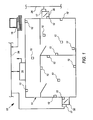
- Fig. 1 shows an arrangement 10 that includes a plurality of wireless microsystems 12, each microsystem 12 is operable to measure at least relative humidity and temperature parameters in a building environment 14 and is further operable to communicate the parameters (either individually, or combined to form a comfort index) wirelessly to a network device 16.
- the network device 16 is operable to communicate the comfort index information from the plurality of microsystems 12 to room controllers 17.
- the room controllers 17 are operable to generate control signals that cause ventilation shaft dampers 30 to further open or close in order to adjust the flow of supply air (which may be heated or chilled), into the various rooms of the building environment 14.
- the comfort index is a variable representative of a theoretical comfort level based on relative humidity and temperature. It is known that the same temperature may feel comfortable at 50% relative humidity, but less comfortable at much higher or lower humidity values.
- Fig. 4 which will be discussed further below in detail, shows a graph of temperature versus relative humidity.
- the graph of Fig. 4 includes a comfort zone 402 defined by a comfort zone perimeter 404. When both the temperature and relative humidity are at values that fall within the comfort zone 402, the conditions are considered to be comfortable.
- the comfort zone 402 is based on the ASHRAE comfort index standard.
- the comfort index may suitably be a two element vector (t, rh) where t is the "dry bulb" temperature and rh is the relative humidity.
- each comfort vector (t, rh ) identifies a particular point on the graph of Fig. 4 .
- the comfort index/vector (77, 35) is represented as point 408 on the graph of Fig. 4 , and thus falls within the comfort zone 402.
- the vector points of the graph of Fig. 4 may be translated or mapped to single comfort values (e.g. from 1-10) based on perceived comfort at each combination of temperature and relative humidity.
- single comfort values e.g. from 1-10) based on perceived comfort at each combination of temperature and relative humidity.
- the publication "Are Your Customers Comfortable? How Do You Know" by Bill Gnerre and Kevin Fuller (in July 2006 AutomatedBuildings.com) shows one method of creating a table that translates points on the temperature versus relative humidity graph into a comfort index value. Such a table could be stored and used by the microsystems 12 to generate a single comfort index value.
- controllers such as the controller 17 or 18 may translate the comfort vectors (t, rh) to a single value as necessary or desirable.
- the network device 16 and/or the room controllers 17 are further operable to communicate the comfort index information from one or more rooms or microsystems 12 to a central data processor 18 that is able to generate information regarding the comfort index for the building 14 for display, data recording, or for more complex control operations. If the comfort index information is in the form of a (t, rh ) vector, then the central data processor 18 may optionally convert the information to a single index value for use in display or data recording.
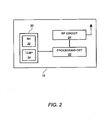
- each microsystem 12 may therefore employ a MEMS sensor suite 20 that includes a MEMS humidity sensor and a MEMS temperature sensor. Other embodiments may include a MEMS flow sensor, if flow is used as a parameter in the comfort index.
- the microsystem 12 may also incorporate processing circuitry 22, as well as radio frequency transmission circuitry 24. General examples of MEMS devices having processing circuitry and RF capability are discussed in U.S. Patent Application US-A-2004/0008651 , forming the preamble of claim 1 and entitled "Building System with Reduced Wiring Requirements and Apparatus for Use Therein", filed January 28, 2003, and U.S.
- the processing circuitry 22 is programmed or otherwise configured to generate a heat or comfort index based on the relative humidity measurements and temperature measurements obtained by the MEMS sensor suite 20.
- the processing circuitry 22 is further operable to cause the RF circuit 24 to communicate that index wirelessly to the network device 16.
- the processing circuitry 22 merely obtains the sensor values and provides those values (preferably with some low pass filtering) to the RF circuit 24 for transmission to the network device 16.
- the RF circuit 24 may suitably use Bluetooth or other short range RF transmission technology.
- the microsystem 12 may further include a battery, not shown, to power the operations.
- the network device 16 may suitably be an RF transceiver connected to a building control system wired or wireless network 26, such that described in U.S. Patent Application US-A-2004/0008651 .
- the network device 16 is co-located with one or more the controllers 17 in a traditional field controller panel as is known in the art.
- the controllers 17 are located proximate to the dampers 30 they control, and may be hardwired or wirelessly connected to the network device 16. The principles of this embodiment of the invention do not require either option over the other.
- the ventilation dampers 30 are devices coupled to chilled or heated supply air shafts, not shown, and which are configured to controllably admit supply air into a room of the building environment 14, as is known in the art.
- the controllers 17 are operably coupled, through actuators, not shown, to cause the ventilation dampers 30 to open or close to adjust the amount of supply (heated or chilled) air into the room.
- further microsystems 12 are provided at or near the ventilation dampers 30 that can measure comfort index-related characteristics (e.g. temperature and/or relative humidity) of the supplied air.
- the controller 17 may therefore use the comfort index information from the room associated with a particular ventilation damper 30 and the conditions of the supply air to determine how much the ventilation damper 30 should be open to help bring the comfort index to an appropriate level. In some cases, the humidity and temperature of the supply air is not required by the controller 17.
- the desired comfort index of a room or space may be determined by a set point provided by the central data processor 18.
- This set point may be a single comfort level value which is then compared to the measured comfort level expressed as a single value as described above (i.e. not as a two-dimensional vector).
- the central data processor 18 may suitably be a computer workstation that is connected to the building control system network 26.
- the central data processor 18 may suitably be a control station of the building control or automation system, such as an INSIGHTTM Workstation available from Siemens Building Technologies, Inc. of Buffalo Grove Illinois, and which is used in the APOGEETM brand automation systems.
- the central data processor 18 may coordinate the received comfort index information from microsystems of a plurality of rooms to execute more sophisticated control modes. To carry out the more sophisticated control modes, the central data processor 18 may recalculate or adjust set points for the comfort index for each of the controllers 17, and communicate the adjusted set points to the controllers 17 via the building network 26.
- Fig. 5 discussed further below, illustrates a set of operations that central data processor 18 may carry out using comfort index information from a plurality of rooms.
- microsystems 12 may be employed extensively throughout the building at a reasonable cost, because of the ability to mass produce the devices.
- the use of MEMS devices as at least the sensors reduces the power consumption of relative humidity and temperature sensing.
- the use of microsystems that employ MEMS devices enables the microsystem to be embodied as a wireless device, due to the low power consumption of the MEMS devices.
- the use of such wireless devices drastic reduces the labor and costs associated with installation by eliminating wiring.
- the microsystems 12 are small and may be placed on walls, fixtures, the floor, and even on moveable objects.
- comfort index as a control set point may be carried out in a variety of other ways.
- the controller 17 receives temperature and humidity information (i.e. as a vector or otherwise) from the sensors 12 and controls the dampers 30 based on the information.
- the controller 17 searches for a room condition that is along the perimeter of the comfort zone to minimize energy consumption. (See, e.g., Fig. 4 ).
- the comfort zone is the range of combined humidity and temperature combinations that satisfy ASHRAE comfort guidelines for human occupants. However, other standards for comfort zones may be used.
- the controller 17 could determine the combination of humidity and temperature that is most economically achieved, given the temperature and humidity of the room and the supply air.
- Such a mode is sometimes referred to as floating point set point control because different rooms or spaces may be controlled to different temperatures based on their humidity levels.
- Fig. 3 shows an exemplary set of operations that employ a simplified type of floating set point control in a room of a building based on comfort index information.
- the room has a plurality of comfort measurement microsystems similar to the microsystem 12 of Figs. 1 and 2 . It is also assumed that the main method of controlling the comfort is to adjust the flow of chilled air into the room via the ventilation damper 30 and its associated controller 17. (See Fig. 1 ).
- Fig. 3 The operations of Fig. 3 are carried out by a field controller such as the controller 17 of Fig. 1 .
- a field controller such as the controller 17 of Fig. 1 .
- each controller 17 performs the operations of Fig. 3 separately for each room for which it controls the ventilation damper 30.
- step 302 the controller 17 obtains the comfort index information for each sensor 12 in the room or space associated with a damper 30.
- each space or room preferably has three to six microsystem devices 12. (See Fig. 1 ).
- the controller 17 receives as many comfort index values.
- the comfort index information is the vector (t, rh) that includes a temperature value and a relative humidity value.
- the controller 17 may suitably receive the sensor values wirelessly, as discussed above in connection with Fig. 1 .
- step 304 the controller 17 generates performs a filter on the index values ( t , rh ) to obtain a comfort value or vector for the room.
- the filter may obtain an average of the index values, a mean of index values, or an average or mean of all but the highest and lowest index values. Other filtering mechanisms may suitably be used.
- the controller 17 after step 304 has a single comfort value or vector (t sn , rh sp ) for the space or room.
- the t sp mean (all t values from microsystems 12 in room)
- rh sp mean (all rh values from microsystems 12 in room).
- step 306 the controller determines whether the comfort value for the room is within the comfort zone thresholds. In particular, the controller determines whether the vector value ( t sp , rh sp ) falls within a predefined comfort zone window. To this end, the controller 17 may effectively plot the vector value ( t sp , rh sp ) against the graph of Fig. 4 . If the vector value ( t sp , rh sp ) falls within the comfort zone 402, then the processing circuit proceeds to step 308. If not, then the controller proceeds to step 310.
- the vector value ( t sp , rh sp ) is (77, 56), such as point 406 of Fig. 4 , then the vector value falls outside the comfort zone 402 and the controller proceeds to step 310. If, however, the vector ( t sp , rh sp ) is (77, 35), such as point 408 of Fig. 4 , then the vector value falls inside the comfort zone 402 of and the controller proceeds to step 308.
- the determination of whether a particular point falls within the comfort zone 402 may be done a number of ways, including determining whether the vector value falls on the proper side of each line or slope that defines the perimeter 404.
- step 310 the controller 17 performs suitable control operations to attempt to change the comfort vector value such that the comfort vector value move toward the comfort zone 402.
- the controller 17 in step 310 will cause the damper 30 to open further to allow more chilled air to advance into the room.
- the controller 17 may determine, based on the temperature information t sp , that the room is too cool, and thus the controller would cause the damper to close to reduce the amount of chilled air that advances into the room.
- the controller 17 may suitably use PI, or PID control techniques to determine how much to adjust the air flow based on the comfort index value and its position vis a vis the comfort zone 402.
- the controller 17 determines whether the comfort value vector ( t sp , rh sp ) , which has already been determined to be within the comfort zone 402, is greater than a threshold distance D thresh from the perimeter 404 of the comfort zone 402.
- vector value identifies an interior point of the comfort zone, such as the point 410, which is at a distance d greater than a threshold distance D thresh from the perimeter 404 of the comfort zone 402
- the air conditioning may be reduced, thereby causing the temperature to rise, but only such that the comfort level remains within the borders of the comfort zone 402.
- the HVAC system may be operating inefficiently because adequate comfort could be maintained while using less energy.
- the cooling air may be reduced, causing the comfort value vector to move from point 410 towards the sloped line between 75°F and 78°. While the temperature (and possibly relative humidity) rises as a result of reduced cooling air, the comfort index may still lie within the acceptable ranges.
- step 308 the controller 17 determines whether the comfort vector value of the room is more than a distance D thresh from the perimeter. If so, then the controller 17 proceeds to step 312. If not, then the controller 17 may suitably return to step 302 and repeat the process, preferably after a predefined time interval.
- step 308 it is simplest to determine whether the comfort vector is at a significant distance from any part of the perimeter 404 and reduce the air flow through the damper 30 as a result thereof.
- step 312 the controller 17 causes the damper 30 to reduce the flow of chilled air into the room. The reduction may be minor, so as to ensure that the comfort index does not fall out of the comfort zone 402. The controller 17 then returns to step 302.
- Fig. 3 shows an exemplary set of operations that may be performed to adjust a damper based on comfort index to achieve a comfortable environment and an efficient system
- Fig. 5 shows an exemplary set of operations that another controller, for example a central control station such as the central data processor 18, may use to control other aspects of building control operations based on comfort level values.
- a processing device that is operable connected to provide control messages or signals a variety of HVAC devices.
- a central control processor such as the central control processor 18 of Fig. 1 would perform such operations.
- the processor obtains comfort index values for a plurality of locations of a facility.
- the processor may obtain comfort vector values ( t sp , rh sp ) for each room or space in the building.
- the processor determines whether the overall comfort level of the building is outside tolerable range. To this end, the processor first determines an overall comfort level based on the received vector values for all (or many) of the spaces in the building.
- the overall comfort level may comprise a mean comfort value, or some weighted or statistically adjusted average of the comfort values for all the rooms and spaces. It will be appreciated that the mean of each of the t sp , rh sp values of the comfort vector ( t sp , rh sp ) is not as useful in determining the overall building comfort. It is not the average temperature and average relative humidity that is most useful, but instead, the average "comfort level". Accordingly, it is more useful to quantify the comfort vector ( t sp , rh sp ) as a single comfort value, such as is discussed further above, prior to determining the overall building comfort level.
- each ( t sp , rh sp ) vector value may be mapped to a single corresponding comfort level (e.g. a value from 1-10).
- This comfort level value is referred to herein as CL.
- the table may indicate that all of the comfort vectors within the comfort zone 402 of Fig. 4 map to CL values of 9 or 10.
- Vectors located just outside the perimeter 404 may map to CL values from 6 to 8, and vectors further afield may map to CL values of 5 or lower.
- the appropriate mapping of comfort vector values ( t sp , rh sp ) to the CL values may be determined experimentally, or using various studies available on the Web, including the Gnerre article. Figs. 2 and 3 of the Gnerre article show one mapping scheme that may be used.
- the controller 17 determines whether the overall building comfort index is below a first threshold. This determination identifies whether overall building comfort level is too low. If so, then the processor proceeds to step 506. If not, then the processor proceeds to step 508.
- the processor causes a change in the supply air responsive to the low overall building comfort.
- the supply air is the air provided to each of the ventilation dampers 30 of a building.
- the cooling and/or heating ability of the HVAC system depends largely on the temperature of the supply air. While individual room comfort may be controlled by allowing more or less chilled or heated supply air into a room, reducing (or increasing) the temperature (flow) of the supply air can greatly enhance the ability of the HVAC system to maintain desirable comfort levels throughout the entire building. As a consequence, if the overall building comfort level is too low, it is helpful to increase the cooling (or heating) capacity of the supply air.
- the processor therefore in step 506 causes the supply air temperature to change in response to the low comfort index.
- suitable control signals may be provided to an air handling unit, not shown, but which is known in the art.
- An air handling unit of a building controls the supply air flow and supply air temperature.
- the processor determines whether individual areas or rooms are below a second comfort threshold, which may suitably be the same as or different from the first threshold. If so, it is an indication that most of the building has an acceptable comfort level, but some areas do not. If some local areas have low comfort levels CL , then the processor proceeds to step 510. If not, the processor proceeds to step 512.
- step 510 the processor causes local controllers in the areas of low comfort to attempt to address the low comfort level using local control. This may involve replacing set points and/or adjusting dampers on the local level, or even using local chilling or heating devices. Such local control devices are known in the art. However, if local control options are exhausted and/or are not efficient, then the processor in step 510 as an alternative adjusts the supply air in a manner similar to that described above in connection with step 506. To this end, it is noted that even if most areas have an adequate comfort level, it may be necessary to change the supply air temperature to ensure that the problem areas have sufficient opportunity to achieve the desired comfort level. In either event, after step 510, the processor returns to step 502.
- the processor determines whether the overall building comfort value exceeds a third threshold.
- the third threshold exceeds the first threshold. If the overall building comfort exceeds the third threshold, it is indicative of a high level of comfort throughout the building, which in turn can indicate inefficient operation of the HVAC system.
- the comfort level is relatively high, it is likely that the cooling (or heating) equipment is running more than necessary.
- step 514 the processor proceeds to step 514 to attempt to address the potentially inefficient operation.
- the processor provides control signals for the supply air that result in reduced power consumption.
- the processor may reduce the chilling of the supply air.
- the processor may reduce the heating of the supply air.
- the overall flow of supply air may be reduced.
- the reduction of flow, or heating or chilling results in less energy consumption by the air handling unit of the HVAC system. Because the overall comfort level of the building is relatively high, it is possible to reduce the cooling (or heating) capability of supply air with reduced risk of making the building uncomfortable.
Description
- The present invention relates to indoor environmental control, and more particularly to HVAC control based at least in part on relative humidity and temperature.
- Buildings in which people work and live have systems that monitor and sustain the comfort level of the building environment. Such systems include heating, ventilation and air conditioning (HVAC) systems, lighting systems, as well as others. HVAC and lighting systems have existed, at least at some level, for thousands of years.
- HVAC and lighting systems have become sophisticated, and are often able to maintain careful balances of humidity and temperature, as well as provide fresh air and adequate light within buildings. Suitable temperature, humidity, light and oxygen levels contribute to the indoor environmental quality of a building or work place. Good environmental quality can translate to better productivity and health of the occupants. The majority of building control systems maintains the occupants comfort by simply maintaining space temperature, which is measured using a thermostat or temperature sensor located on a wall. Although there is a strong correlation between temperature and human comfort, a better comfort index can be measured when the temperature is combined with relative humidity.
- Combined temperature and humidity level is a better measure of heat or thermal energy content in a room and it is that thermal energy that needs to be removed (i.e. cooled) or supplemented by more energy (i.e. heated) to maintain the occupants at a comfortable level. The combined temperature and humidity levels are often termed as the "heat index" by the meteorological media.
- As yet, however, there has been limited application of the combined heat/humidity index in the building control or HVAC industry. Costs related to sensing both temperature and relative humidity on a comprehensive scale has hindered such applications.
- There is a need, therefore, for a cost-effective solution for implementing comfort control in buildings that takes into account both relative humidity and temperature.
- The present invention addresses the above described needs, as well as others, by employing wireless MEMS microsystems that may be produced in bulk, and which measure both temperature and relative humidity, and communicate information representative of the measured information, preferably wirelessly, to data processing equipment.
- A first embodiment of the invention is an arrangement that includes a plurality of wireless microsystems, each microsystem operable to measure at least relative humidity and temperature. Each microsystem is preferably operable to calculate and communicate a combined temperature and relative humidity index and communicate the heat index wirelessly to a network device. In other embodiments, the microsystem transmits both temperature and relative humidity measured data and the index is calculated in another part of the system. In either event, the network device is operable to communicate the parameters to one or more controllers that can adjust flow rate of heated or cooled air to a room based on the heat index.
- In some cases, when the heated and/or cooled air is provided to each room via a ventilation system, the heat index of the chilled and/or cooled air is also known or obtained through the use of microsystems. In such a case, when the controller adjusts the flow rate, the controller takes into account the temperature/relative humidity information of the supply air as well as the temperature/relative humidity information for each room.
- In other embodiments, some or all of the microsystems need not be wireless. However, there is an advantage to the use of wireless microsystems because it reduces labor and material costs associated with running wires.
- The above described features and advantages, as well as others, will become more readily apparent to those of ordinary skill in the art by reference to the following detailed description and accompanying drawings.
-
-
Fig. 1 shows a schematic block diagram of an exemplary embodiment of an arrangement according to the invention; -
Fig. 2 shows a block diagram of an exemplary microsystem device that may be used in the arrangement ofFig. 1 ; -
Fig. 3 shows a flow diagram of an exemplary set of operations that may be used by a ventilation damper controller for a space in accordance with one embodiment of the invention; -
Fig. 4 shows a temperature vs. relative humidity graph that identifies an exemplary comfort zone; and -
Fig. 5 shows a flow diagram of an exemplary set of operations that may be used by a central controller for a building using comfort level information in accordance with one embodiment of the invention. -
Fig. 1 shows anarrangement 10 that includes a plurality ofwireless microsystems 12, eachmicrosystem 12 is operable to measure at least relative humidity and temperature parameters in abuilding environment 14 and is further operable to communicate the parameters (either individually, or combined to form a comfort index) wirelessly to anetwork device 16. Thenetwork device 16 is operable to communicate the comfort index information from the plurality ofmicrosystems 12 toroom controllers 17. Theroom controllers 17 are operable to generate control signals that causeventilation shaft dampers 30 to further open or close in order to adjust the flow of supply air (which may be heated or chilled), into the various rooms of thebuilding environment 14. - The comfort index is a variable representative of a theoretical comfort level based on relative humidity and temperature. It is known that the same temperature may feel comfortable at 50% relative humidity, but less comfortable at much higher or lower humidity values.
Fig. 4 , which will be discussed further below in detail, shows a graph of temperature versus relative humidity. The graph ofFig. 4 includes acomfort zone 402 defined by acomfort zone perimeter 404. When both the temperature and relative humidity are at values that fall within thecomfort zone 402, the conditions are considered to be comfortable. Thecomfort zone 402 is based on the ASHRAE comfort index standard. - In some embodiments described herein, the comfort index may suitably be a two element vector (t, rh) where t is the "dry bulb" temperature and rh is the relative humidity. Thus, each comfort vector (t, rh) identifies a particular point on the graph of
Fig. 4 . For example, the comfort index/vector (77, 35) is represented aspoint 408 on the graph ofFig. 4 , and thus falls within thecomfort zone 402. - In other embodiments, the vector points of the graph of
Fig. 4 may be translated or mapped to single comfort values (e.g. from 1-10) based on perceived comfort at each combination of temperature and relative humidity. For example, the publication "Are Your Customers Comfortable? How Do You Know" by Bill Gnerre and Kevin Fuller (in July 2006 AutomatedBuildings.com), shows one method of creating a table that translates points on the temperature versus relative humidity graph into a comfort index value. Such a table could be stored and used by themicrosystems 12 to generate a single comfort index value. In other embodiments, controllers such as thecontroller - In any event, the
network device 16 and/or theroom controllers 17 are further operable to communicate the comfort index information from one or more rooms ormicrosystems 12 to acentral data processor 18 that is able to generate information regarding the comfort index for thebuilding 14 for display, data recording, or for more complex control operations. If the comfort index information is in the form of a (t, rh) vector, then thecentral data processor 18 may optionally convert the information to a single index value for use in display or data recording. - Referring to
Fig. 2 , the current state of the art of microsystems is sufficient to create a microsystem operable to measure and/or monitor temperature and relative humidity parameters. Eachmicrosystem 12 may therefore employ aMEMS sensor suite 20 that includes a MEMS humidity sensor and a MEMS temperature sensor. Other embodiments may include a MEMS flow sensor, if flow is used as a parameter in the comfort index. Themicrosystem 12 may also incorporateprocessing circuitry 22, as well as radiofrequency transmission circuitry 24. General examples of MEMS devices having processing circuitry and RF capability are discussed in U.S. Patent ApplicationUS-A-2004/0008651 , forming the preamble of claim 1 and entitled "Building System with Reduced Wiring Requirements and Apparatus for Use Therein", filed January 28, 2003, and U.S. - Patent Application Serial No.
US-A-2004 41 44849 entitled "Building Control System Using Integrated MEMS Device". Other devices of this nature are known. - In one embodiment, the
processing circuitry 22 is programmed or otherwise configured to generate a heat or comfort index based on the relative humidity measurements and temperature measurements obtained by theMEMS sensor suite 20. Theprocessing circuitry 22 is further operable to cause theRF circuit 24 to communicate that index wirelessly to thenetwork device 16. In other embodiments, theprocessing circuitry 22 merely obtains the sensor values and provides those values (preferably with some low pass filtering) to theRF circuit 24 for transmission to thenetwork device 16. TheRF circuit 24 may suitably use Bluetooth or other short range RF transmission technology. Themicrosystem 12 may further include a battery, not shown, to power the operations. - Referring again to
Fig. 1 , thenetwork device 16 may suitably be an RF transceiver connected to a building control system wired orwireless network 26, such that described in U.S. Patent ApplicationUS-A-2004/0008651 . In some embodiments, thenetwork device 16 is co-located with one or more thecontrollers 17 in a traditional field controller panel as is known in the art. However, in the disclosed embodiment, thecontrollers 17 are located proximate to thedampers 30 they control, and may be hardwired or wirelessly connected to thenetwork device 16. The principles of this embodiment of the invention do not require either option over the other. - The
ventilation dampers 30 are devices coupled to chilled or heated supply air shafts, not shown, and which are configured to controllably admit supply air into a room of thebuilding environment 14, as is known in the art. Thecontrollers 17 are operably coupled, through actuators, not shown, to cause theventilation dampers 30 to open or close to adjust the amount of supply (heated or chilled) air into the room. In the embodiment described herein,further microsystems 12 are provided at or near theventilation dampers 30 that can measure comfort index-related characteristics (e.g. temperature and/or relative humidity) of the supplied air. Thecontroller 17 may therefore use the comfort index information from the room associated with aparticular ventilation damper 30 and the conditions of the supply air to determine how much theventilation damper 30 should be open to help bring the comfort index to an appropriate level. In some cases, the humidity and temperature of the supply air is not required by thecontroller 17. - The desired comfort index of a room or space may be determined by a set point provided by the
central data processor 18. This set point may be a single comfort level value which is then compared to the measured comfort level expressed as a single value as described above (i.e. not as a two-dimensional vector). - The
central data processor 18 may suitably be a computer workstation that is connected to the buildingcontrol system network 26. In the embodiment in which thearrangement 10 uses a building control system network, then thecentral data processor 18 may suitably be a control station of the building control or automation system, such as an INSIGHT™ Workstation available from Siemens Building Technologies, Inc. of Buffalo Grove Illinois, and which is used in the APOGEE™ brand automation systems. - The
central data processor 18 may coordinate the received comfort index information from microsystems of a plurality of rooms to execute more sophisticated control modes. To carry out the more sophisticated control modes, thecentral data processor 18 may recalculate or adjust set points for the comfort index for each of thecontrollers 17, and communicate the adjusted set points to thecontrollers 17 via thebuilding network 26.Fig. 5 , discussed further below, illustrates a set of operations thatcentral data processor 18 may carry out using comfort index information from a plurality of rooms. - One advantage of some embodiments of the invention is that the
microsystems 12 may be employed extensively throughout the building at a reasonable cost, because of the ability to mass produce the devices. The use of MEMS devices as at least the sensors reduces the power consumption of relative humidity and temperature sensing. Moreover, the use of microsystems that employ MEMS devices enables the microsystem to be embodied as a wireless device, due to the low power consumption of the MEMS devices. The use of such wireless devices drastic reduces the labor and costs associated with installation by eliminating wiring. In addition, themicrosystems 12 are small and may be placed on walls, fixtures, the floor, and even on moveable objects. - The use of comfort index as a control set point may be carried out in a variety of other ways. In one mode, the
controller 17 receives temperature and humidity information (i.e. as a vector or otherwise) from thesensors 12 and controls thedampers 30 based on the information. In this mode, thecontroller 17 searches for a room condition that is along the perimeter of the comfort zone to minimize energy consumption. (See, e.g.,Fig. 4 ). The comfort zone is the range of combined humidity and temperature combinations that satisfy ASHRAE comfort guidelines for human occupants. However, other standards for comfort zones may be used. In the economic mode, thecontroller 17 could determine the combination of humidity and temperature that is most economically achieved, given the temperature and humidity of the room and the supply air. - Such a mode is sometimes referred to as floating point set point control because different rooms or spaces may be controlled to different temperatures based on their humidity levels.
-
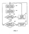
Fig. 3 shows an exemplary set of operations that employ a simplified type of floating set point control in a room of a building based on comfort index information. In the set of operations ofFig. 3 , it will be assumed that the room has a plurality of comfort measurement microsystems similar to themicrosystem 12 ofFigs. 1 and2 . It is also assumed that the main method of controlling the comfort is to adjust the flow of chilled air into the room via theventilation damper 30 and its associatedcontroller 17. (SeeFig. 1 ). - The operations of
Fig. 3 are carried out by a field controller such as thecontroller 17 ofFig. 1 . In the embodiment ofFig. 1 , eachcontroller 17 performs the operations ofFig. 3 separately for each room for which it controls theventilation damper 30. - In
step 302, thecontroller 17 obtains the comfort index information for eachsensor 12 in the room or space associated with adamper 30. In this embodiment, each space or room preferably has three to sixmicrosystem devices 12. (SeeFig. 1 ). Thus, thecontroller 17 receives as many comfort index values. In the operations ofFig. 3 , it is assumed that the comfort index information is the vector (t, rh) that includes a temperature value and a relative humidity value. Thecontroller 17 may suitably receive the sensor values wirelessly, as discussed above in connection withFig. 1 . - In
step 304, thecontroller 17 generates performs a filter on the index values (t, rh) to obtain a comfort value or vector for the room. The filter may obtain an average of the index values, a mean of index values, or an average or mean of all but the highest and lowest index values. Other filtering mechanisms may suitably be used. Thecontroller 17 afterstep 304 has a single comfort value or vector (tsn, rhsp) for the space or room. In this example, the tsp = mean (all t values frommicrosystems 12 in room), and rhsp = mean (all rh values frommicrosystems 12 in room). - In
step 306, the controller determines whether the comfort value for the room is within the comfort zone thresholds. In particular, the controller determines whether the vector value (tsp, rhsp ) falls within a predefined comfort zone window. To this end, thecontroller 17 may effectively plot the vector value (tsp, rhsp ) against the graph ofFig. 4 . If the vector value (tsp, rhsp ) falls within thecomfort zone 402, then the processing circuit proceeds to step 308. If not, then the controller proceeds to step 310. - Thus, for example, if the vector value (tsp, rhsp ) is (77, 56), such as
point 406 ofFig. 4 , then the vector value falls outside thecomfort zone 402 and the controller proceeds to step 310. If, however, the vector (tsp , rhsp ) is (77, 35), such aspoint 408 ofFig. 4 , then the vector value falls inside thecomfort zone 402 of and the controller proceeds to step 308. The determination of whether a particular point falls within thecomfort zone 402 may be done a number of ways, including determining whether the vector value falls on the proper side of each line or slope that defines theperimeter 404. - Referring again to
Fig. 3 , in step 310 (vector outside of comfort zone 402), thecontroller 17 performs suitable control operations to attempt to change the comfort vector value such that the comfort vector value move toward thecomfort zone 402. In general, thecontroller 17 instep 310 will cause thedamper 30 to open further to allow more chilled air to advance into the room. However, thecontroller 17 may determine, based on the temperature information tsp, that the room is too cool, and thus the controller would cause the damper to close to reduce the amount of chilled air that advances into the room. Thecontroller 17 may suitably use PI, or PID control techniques to determine how much to adjust the air flow based on the comfort index value and its position vis a vis thecomfort zone 402. - Referring again to step 308 (vector value in the comfort zone 402), the
controller 17 determines whether the comfort value vector (tsp, rhsp ), which has already been determined to be within thecomfort zone 402, is greater than a threshold distance Dthresh from theperimeter 404 of thecomfort zone 402. In general, if vector value identifies an interior point of the comfort zone, such as thepoint 410, which is at a distance d greater than a threshold distance Dthresh from theperimeter 404 of thecomfort zone 402, then it is known that less chilled air may be advanced into the room without causing the room comfort index to move completely out of the comfort zone. In other words, the air conditioning may be reduced, thereby causing the temperature to rise, but only such that the comfort level remains within the borders of thecomfort zone 402. - If the vector value (tsp, rhsp ) is greater than the threshold distance Dthresh from the
perimeter 404, then the HVAC system may be operating inefficiently because adequate comfort could be maintained while using less energy. Thus, for example, if the current comfort value vector is atpoint 410, then the cooling air may be reduced, causing the comfort value vector to move frompoint 410 towards the sloped line between 75°F and 78°. While the temperature (and possibly relative humidity) rises as a result of reduced cooling air, the comfort index may still lie within the acceptable ranges. - Thus, in
step 308, thecontroller 17 determines whether the comfort vector value of the room is more than a distance Dthresh from the perimeter. If so, then thecontroller 17 proceeds to step 312. If not, then thecontroller 17 may suitably return to step 302 and repeat the process, preferably after a predefined time interval. - It is noted that it is possible that even if a vector value is on the
perimeter 404, inefficiencies may still exist if the vector value is situated on the "wrong" side of the perimeter. For example, if the vector value of a room is (69, 40) during the summer season, and thus the vector value is very near or on the left border of theperimeter 404, it is likely still possible to significantly reduce the chilled air into the room without danger of moving out of the comfort zone. In such a case, the HVAC system is operating inefficiently despite the fact that the vector value is very close to theperimeter 404. As a consequence, while the determination of whether the comfort value vector is more than a threshold distance from theperimeter 404 can identify instances of inefficiency, it cannot identify all instances of inefficiency. - Those of ordinary skill in the art may readily devise additional or alternative determinations in
step 308 to detect such inefficient conditions and move to step 312 as a result thereof. However, in the rudimentary example described herein, it is simplest to determine whether the comfort vector is at a significant distance from any part of theperimeter 404 and reduce the air flow through thedamper 30 as a result thereof. - Regardless, in
step 312, thecontroller 17 causes thedamper 30 to reduce the flow of chilled air into the room. The reduction may be minor, so as to ensure that the comfort index does not fall out of thecomfort zone 402. Thecontroller 17 then returns to step 302. - While
Fig. 3 shows an exemplary set of operations that may be performed to adjust a damper based on comfort index to achieve a comfortable environment and an efficient system, there are also uses for the comfort information gathered by microsystems in other building control operations. For example,Fig. 5 shows an exemplary set of operations that another controller, for example a central control station such as thecentral data processor 18, may use to control other aspects of building control operations based on comfort level values. - Referring now to
Fig. 5 , the operations described herein may suitably be performed by a processing device that is operable connected to provide control messages or signals a variety of HVAC devices. Ordinarily, a central control processor such as thecentral control processor 18 ofFig. 1 would perform such operations. - In
step 502, the processor obtains comfort index values for a plurality of locations of a facility. For example, the processor may obtain comfort vector values (tsp, rhsp ) for each room or space in the building. - In
step 504, the processor determines whether the overall comfort level of the building is outside tolerable range. To this end, the processor first determines an overall comfort level based on the received vector values for all (or many) of the spaces in the building. The overall comfort level may comprise a mean comfort value, or some weighted or statistically adjusted average of the comfort values for all the rooms and spaces. It will be appreciated that the mean of each of the tsp, rhsp values of the comfort vector (tsp , rhsp ) is not as useful in determining the overall building comfort. It is not the average temperature and average relative humidity that is most useful, but instead, the average "comfort level". Accordingly, it is more useful to quantify the comfort vector (tsp , rhsp ) as a single comfort value, such as is discussed further above, prior to determining the overall building comfort level. - To this end, as discussed above and in the Gnerre article, each (tsp , rhsp) vector value may be mapped to a single corresponding comfort level (e.g. a value from 1-10). This comfort level value is referred to herein as CL. The value CL is expressed as CL = F(tsp, rhsp ), where F is a function that could include a table lookup of a CL value assigned to each potential vector value (tsp, rhsp ). By way of example, the table may indicate that all of the comfort vectors within the
comfort zone 402 ofFig. 4 map to CL values of 9 or 10. Vectors located just outside theperimeter 404 may map to CL values from 6 to 8, and vectors further afield may map to CL values of 5 or lower. The appropriate mapping of comfort vector values (tsp , rhsp ) to the CL values may be determined experimentally, or using various studies available on the Web, including the Gnerre article.Figs. 2 and3 of the Gnerre article show one mapping scheme that may be used. - Thus, for the remainder of the discussion of
Fig. 5 , it will be assumed that the comfort value for each room has been converted to a single comfort value CL as opposed to a two-dimensional vector (tsp, rhsp ). - Referring again to step 504, the
controller 17 determines whether the overall building comfort index is below a first threshold. This determination identifies whether overall building comfort level is too low. If so, then the processor proceeds to step 506. If not, then the processor proceeds to step 508. - In step 506 (overall building comfort low), the processor causes a change in the supply air responsive to the low overall building comfort. The supply air, as is well known in the art, is the air provided to each of the
ventilation dampers 30 of a building. Ultimately, the cooling and/or heating ability of the HVAC system depends largely on the temperature of the supply air. While individual room comfort may be controlled by allowing more or less chilled or heated supply air into a room, reducing (or increasing) the temperature (flow) of the supply air can greatly enhance the ability of the HVAC system to maintain desirable comfort levels throughout the entire building. As a consequence, if the overall building comfort level is too low, it is helpful to increase the cooling (or heating) capacity of the supply air. The processor therefore instep 506 causes the supply air temperature to change in response to the low comfort index. To this end, suitable control signals may be provided to an air handling unit, not shown, but which is known in the art. An air handling unit of a building controls the supply air flow and supply air temperature. - Referring to step 508 (overall building comfort level not low), the processor determines whether individual areas or rooms are below a second comfort threshold, which may suitably be the same as or different from the first threshold. If so, it is an indication that most of the building has an acceptable comfort level, but some areas do not. If some local areas have low comfort levels CL, then the processor proceeds to step 510. If not, the processor proceeds to step 512.
- In
step 510, the processor causes local controllers in the areas of low comfort to attempt to address the low comfort level using local control. This may involve replacing set points and/or adjusting dampers on the local level, or even using local chilling or heating devices. Such local control devices are known in the art. However, if local control options are exhausted and/or are not efficient, then the processor instep 510 as an alternative adjusts the supply air in a manner similar to that described above in connection withstep 506. To this end, it is noted that even if most areas have an adequate comfort level, it may be necessary to change the supply air temperature to ensure that the problem areas have sufficient opportunity to achieve the desired comfort level. In either event, afterstep 510, the processor returns to step 502. - Referring now to step 512 (no individual area has low comfort), the processor determines whether the overall building comfort value exceeds a third threshold. The third threshold exceeds the first threshold. If the overall building comfort exceeds the third threshold, it is indicative of a high level of comfort throughout the building, which in turn can indicate inefficient operation of the HVAC system. By way of analogy, if a person is comfortable at 75°F, then it is inefficient to set an air condition thermostat to 70°F. If the comfort level is relatively high, it is likely that the cooling (or heating) equipment is running more than necessary.
- Thus, if the overall building comfort level does not exceed the third threshold then the processor simply returns to step 502. If, however, the overall building comfort level exceeds the higher third threshold, then the processor proceeds to step 514 to attempt to address the potentially inefficient operation.
- In
step 514, the processor provides control signals for the supply air that result in reduced power consumption. By way of example, if it is summer, the processor may reduce the chilling of the supply air. In winter, the processor may reduce the heating of the supply air. In some cases, the overall flow of supply air may be reduced. Such changes to the supply air may all be carried out in most commercially available air handling units. The reduction of flow, or heating or chilling, results in less energy consumption by the air handling unit of the HVAC system. Because the overall comfort level of the building is relatively high, it is possible to reduce the cooling (or heating) capability of supply air with reduced risk of making the building uncomfortable. - The above-described operations benefit at least in part from the fact that building comfort does not necessarily require maintaining a strict temperature throughout a building. Instead, higher temperatures or lower temperatures may be tolerated if the combined temperature and humidity provides a comfortable environment. It will be noted that the above systems may be modified to take room air flow into account in comfort calculations and control. It is known that increased room air flow can increase comfort for a given temperature and humidity point.
- It will appreciated that the above described embodiments are exemplary, and that those of ordinary skill in the art may readily devise their own implementations and modifications that incorporate the principles of the invention and fall within the scope of the claims.
Claims (8)
- An arrangement comprising a microsystem operable to measure relative humidity and temperature, characterised in that the arrangement comprises:a plurality of wireless microsystems (12), each microsystem (12) operable to measure at least relative humidity and temperature, to generate a combined temperature and relative humidity index, and to transmit the index wirelessly;a network device (16) operably coupled to receive the transmitted index from each of the plurality of microsystems (12) and to provide as an output information corresponding to the received indices;a controller (17, 18) operably coupled to receive the information corresponding to the indices from the network device (16), the controller operable to cause a change in a building control condition based at least in part on the information.
- The arrangement of claim 1, wherein each index includes a vector including relative humidity and temperature information.
- The arrangement of claim 1, wherein each index includes a single value representative of a combined relative humidity and temperature index.
- The arrangement of claim 1, wherein the information corresponding to a received index is the received index.
- The arrangement of any of the preceding claims, wherein the network device (16) is coupled to the controller (17, 18) via a wired communication network (26).
- The arrangement of any of claims 1 to 4, wherein the network device (16) is co-located with the controller (17).
- The arrangement of any of the preceding claims, wherein the building control condition constitutes an air flow into at least a first space.
- The arrangement of any of claims 1 to 6, wherein the building control condition constitutes a supply air parameter, the supply air provided to a plurality of spaces in a building.
Applications Claiming Priority (2)
| Application Number | Priority Date | Filing Date | Title |
|---|---|---|---|
| US71304205P | 2005-08-30 | 2005-08-30 | |
| PCT/US2006/033566 WO2007027632A2 (en) | 2005-08-30 | 2006-08-30 | Application of microsystems for comfort control |
Publications (2)
| Publication Number | Publication Date |
|---|---|
| EP1932065A2 EP1932065A2 (en) | 2008-06-18 |
| EP1932065B1 true EP1932065B1 (en) | 2015-08-12 |
Family
ID=37526979
Family Applications (1)
| Application Number | Title | Priority Date | Filing Date |
|---|---|---|---|
| EP06802508.9A Active EP1932065B1 (en) | 2005-08-30 | 2006-08-30 | Arrangement of microsystems for comfort control |
Country Status (4)
| Country | Link |
|---|---|
| US (1) | US7854389B2 (en) |
| EP (1) | EP1932065B1 (en) |
| CN (1) | CN101809514B (en) |
| WO (1) | WO2007027632A2 (en) |
Families Citing this family (143)
| Publication number | Priority date | Publication date | Assignee | Title |
|---|---|---|---|---|
| US7623028B2 (en) | 2004-05-27 | 2009-11-24 | Lawrence Kates | System and method for high-sensitivity sensor |
| US8033479B2 (en) | 2004-10-06 | 2011-10-11 | Lawrence Kates | Electronically-controlled register vent for zone heating and cooling |
| ATE497133T1 (en) * | 2004-11-09 | 2011-02-15 | Truveon Corp | BUILDING CLIMATE CONTROL METHOD AND SYSTEM |
| US9037152B1 (en) | 2005-11-12 | 2015-05-19 | Alberto Herrera | Small footprint real-time operating system for reactive systems |
| US7784704B2 (en) | 2007-02-09 | 2010-08-31 | Harter Robert J | Self-programmable thermostat |
| US8160752B2 (en) | 2008-09-30 | 2012-04-17 | Zome Networks, Inc. | Managing energy usage |
| US20090242651A1 (en) * | 2008-03-31 | 2009-10-01 | Computime, Ltd. | Local Comfort Zone Control |
| US8356760B2 (en) * | 2008-04-17 | 2013-01-22 | Riley Jr Claude Roger | Apparent temperature controller |
| KR101679840B1 (en) * | 2008-07-18 | 2016-11-25 | 삼성전자주식회사 | Method for air conditioner |
| US8346398B2 (en) * | 2008-08-08 | 2013-01-01 | Siemens Industry, Inc. | Data center thermal performance optimization using distributed cooling systems |
| US8463443B2 (en) | 2008-10-27 | 2013-06-11 | Lennox Industries, Inc. | Memory recovery scheme and data structure in a heating, ventilation and air conditioning network |
| US8774210B2 (en) | 2008-10-27 | 2014-07-08 | Lennox Industries, Inc. | Communication protocol system and method for a distributed-architecture heating, ventilation and air conditioning network |
| US9632490B2 (en) | 2008-10-27 | 2017-04-25 | Lennox Industries Inc. | System and method for zoning a distributed architecture heating, ventilation and air conditioning network |
| US9678486B2 (en) | 2008-10-27 | 2017-06-13 | Lennox Industries Inc. | Device abstraction system and method for a distributed-architecture heating, ventilation and air conditioning system |
| US8352081B2 (en) | 2008-10-27 | 2013-01-08 | Lennox Industries Inc. | Communication protocol system and method for a distributed-architecture heating, ventilation and air conditioning network |
| US8560125B2 (en) | 2008-10-27 | 2013-10-15 | Lennox Industries | Communication protocol system and method for a distributed-architecture heating, ventilation and air conditioning network |
| US8892797B2 (en) | 2008-10-27 | 2014-11-18 | Lennox Industries Inc. | Communication protocol system and method for a distributed-architecture heating, ventilation and air conditioning network |
| US8433446B2 (en) | 2008-10-27 | 2013-04-30 | Lennox Industries, Inc. | Alarm and diagnostics system and method for a distributed-architecture heating, ventilation and air conditioning network |
| US8452456B2 (en) | 2008-10-27 | 2013-05-28 | Lennox Industries Inc. | System and method of use for a user interface dashboard of a heating, ventilation and air conditioning network |
| US8600558B2 (en) | 2008-10-27 | 2013-12-03 | Lennox Industries Inc. | System recovery in a heating, ventilation and air conditioning network |
| US8255086B2 (en) | 2008-10-27 | 2012-08-28 | Lennox Industries Inc. | System recovery in a heating, ventilation and air conditioning network |
| US8437877B2 (en) | 2008-10-27 | 2013-05-07 | Lennox Industries Inc. | System recovery in a heating, ventilation and air conditioning network |
| US8661165B2 (en) | 2008-10-27 | 2014-02-25 | Lennox Industries, Inc. | Device abstraction system and method for a distributed architecture heating, ventilation and air conditioning system |
| US8239066B2 (en) | 2008-10-27 | 2012-08-07 | Lennox Industries Inc. | System and method of use for a user interface dashboard of a heating, ventilation and air conditioning network |
| US8655490B2 (en) | 2008-10-27 | 2014-02-18 | Lennox Industries, Inc. | System and method of use for a user interface dashboard of a heating, ventilation and air conditioning network |
| US8437878B2 (en) | 2008-10-27 | 2013-05-07 | Lennox Industries Inc. | Alarm and diagnostics system and method for a distributed architecture heating, ventilation and air conditioning network |
| US8442693B2 (en) | 2008-10-27 | 2013-05-14 | Lennox Industries, Inc. | System and method of use for a user interface dashboard of a heating, ventilation and air conditioning network |
| US8543243B2 (en) | 2008-10-27 | 2013-09-24 | Lennox Industries, Inc. | System and method of use for a user interface dashboard of a heating, ventilation and air conditioning network |
| US9377768B2 (en) | 2008-10-27 | 2016-06-28 | Lennox Industries Inc. | Memory recovery scheme and data structure in a heating, ventilation and air conditioning network |
| US9432208B2 (en) | 2008-10-27 | 2016-08-30 | Lennox Industries Inc. | Device abstraction system and method for a distributed architecture heating, ventilation and air conditioning system |
| US8762666B2 (en) | 2008-10-27 | 2014-06-24 | Lennox Industries, Inc. | Backup and restoration of operation control data in a heating, ventilation and air conditioning network |
| US8352080B2 (en) | 2008-10-27 | 2013-01-08 | Lennox Industries Inc. | Communication protocol system and method for a distributed-architecture heating, ventilation and air conditioning network |
| US8694164B2 (en) | 2008-10-27 | 2014-04-08 | Lennox Industries, Inc. | Interactive user guidance interface for a heating, ventilation and air conditioning system |
| US8874815B2 (en) | 2008-10-27 | 2014-10-28 | Lennox Industries, Inc. | Communication protocol system and method for a distributed architecture heating, ventilation and air conditioning network |
| US8744629B2 (en) | 2008-10-27 | 2014-06-03 | Lennox Industries Inc. | System and method of use for a user interface dashboard of a heating, ventilation and air conditioning network |
| US9325517B2 (en) | 2008-10-27 | 2016-04-26 | Lennox Industries Inc. | Device abstraction system and method for a distributed-architecture heating, ventilation and air conditioning system |
| US8615326B2 (en) | 2008-10-27 | 2013-12-24 | Lennox Industries Inc. | System and method of use for a user interface dashboard of a heating, ventilation and air conditioning network |
| US9152155B2 (en) | 2008-10-27 | 2015-10-06 | Lennox Industries Inc. | Device abstraction system and method for a distributed-architecture heating, ventilation and air conditioning system |
| US8295981B2 (en) | 2008-10-27 | 2012-10-23 | Lennox Industries Inc. | Device commissioning in a heating, ventilation and air conditioning network |
| US8655491B2 (en) | 2008-10-27 | 2014-02-18 | Lennox Industries Inc. | Alarm and diagnostics system and method for a distributed architecture heating, ventilation and air conditioning network |
| US8548630B2 (en) | 2008-10-27 | 2013-10-01 | Lennox Industries, Inc. | Alarm and diagnostics system and method for a distributed-architecture heating, ventilation and air conditioning network |
| US8788100B2 (en) | 2008-10-27 | 2014-07-22 | Lennox Industries Inc. | System and method for zoning a distributed-architecture heating, ventilation and air conditioning network |
| US8994539B2 (en) | 2008-10-27 | 2015-03-31 | Lennox Industries, Inc. | Alarm and diagnostics system and method for a distributed-architecture heating, ventilation and air conditioning network |
| US8452906B2 (en) | 2008-10-27 | 2013-05-28 | Lennox Industries, Inc. | Communication protocol system and method for a distributed-architecture heating, ventilation and air conditioning network |
| US8725298B2 (en) | 2008-10-27 | 2014-05-13 | Lennox Industries, Inc. | Alarm and diagnostics system and method for a distributed architecture heating, ventilation and conditioning network |
| US8798796B2 (en) | 2008-10-27 | 2014-08-05 | Lennox Industries Inc. | General control techniques in a heating, ventilation and air conditioning network |
| US9268345B2 (en) | 2008-10-27 | 2016-02-23 | Lennox Industries Inc. | System and method of use for a user interface dashboard of a heating, ventilation and air conditioning network |
| US8855825B2 (en) | 2008-10-27 | 2014-10-07 | Lennox Industries Inc. | Device abstraction system and method for a distributed-architecture heating, ventilation and air conditioning system |
| US8802981B2 (en) | 2008-10-27 | 2014-08-12 | Lennox Industries Inc. | Flush wall mount thermostat and in-set mounting plate for a heating, ventilation and air conditioning system |
| US8564400B2 (en) | 2008-10-27 | 2013-10-22 | Lennox Industries, Inc. | Communication protocol system and method for a distributed-architecture heating, ventilation and air conditioning network |
| US8600559B2 (en) | 2008-10-27 | 2013-12-03 | Lennox Industries Inc. | Method of controlling equipment in a heating, ventilation and air conditioning network |
| US8977794B2 (en) | 2008-10-27 | 2015-03-10 | Lennox Industries, Inc. | Communication protocol system and method for a distributed-architecture heating, ventilation and air conditioning network |
| US9651925B2 (en) | 2008-10-27 | 2017-05-16 | Lennox Industries Inc. | System and method for zoning a distributed-architecture heating, ventilation and air conditioning network |
| US8463442B2 (en) | 2008-10-27 | 2013-06-11 | Lennox Industries, Inc. | Alarm and diagnostics system and method for a distributed architecture heating, ventilation and air conditioning network |
| US9261888B2 (en) | 2008-10-27 | 2016-02-16 | Lennox Industries Inc. | System and method of use for a user interface dashboard of a heating, ventilation and air conditioning network |
| US8831785B2 (en) * | 2008-10-30 | 2014-09-09 | Hewlett-Packard Development Company, L.P. | Multi-stage humidity control system and method |
| US8754775B2 (en) | 2009-03-20 | 2014-06-17 | Nest Labs, Inc. | Use of optical reflectance proximity detector for nuisance mitigation in smoke alarms |
| US9020647B2 (en) * | 2009-03-27 | 2015-04-28 | Siemens Industry, Inc. | System and method for climate control set-point optimization based on individual comfort |
| CA2661261A1 (en) * | 2009-04-03 | 2010-10-03 | Brian Larson | System, apparatus and method for monitoring various environmental conditions surrounding an animal and communicating same to a remote device |
| USD648642S1 (en) | 2009-10-21 | 2011-11-15 | Lennox Industries Inc. | Thin cover plate for an electronic system controller |
| USD648641S1 (en) | 2009-10-21 | 2011-11-15 | Lennox Industries Inc. | Thin cover plate for an electronic system controller |
| US8260444B2 (en) | 2010-02-17 | 2012-09-04 | Lennox Industries Inc. | Auxiliary controller of a HVAC system |
| EP2372483B1 (en) | 2010-03-16 | 2012-10-31 | Siemens Aktiengesellschaft | Method for regulating a room comfort quantity |
| JP5535320B2 (en) * | 2010-08-18 | 2014-07-02 | 三菱電機株式会社 | Air conditioning control device, air conditioning control method and program |
| US8510255B2 (en) | 2010-09-14 | 2013-08-13 | Nest Labs, Inc. | Occupancy pattern detection, estimation and prediction |
| US8918219B2 (en) | 2010-11-19 | 2014-12-23 | Google Inc. | User friendly interface for control unit |
| US8606374B2 (en) | 2010-09-14 | 2013-12-10 | Nest Labs, Inc. | Thermodynamic modeling for enclosures |
| US9104211B2 (en) | 2010-11-19 | 2015-08-11 | Google Inc. | Temperature controller with model-based time to target calculation and display |
| US8950686B2 (en) | 2010-11-19 | 2015-02-10 | Google Inc. | Control unit with automatic setback capability |
| US8727611B2 (en) | 2010-11-19 | 2014-05-20 | Nest Labs, Inc. | System and method for integrating sensors in thermostats |
| US9714772B2 (en) | 2010-11-19 | 2017-07-25 | Google Inc. | HVAC controller configurations that compensate for heating caused by direct sunlight |
| US10346275B2 (en) | 2010-11-19 | 2019-07-09 | Google Llc | Attributing causation for energy usage and setpoint changes with a network-connected thermostat |
| US9448567B2 (en) | 2010-11-19 | 2016-09-20 | Google Inc. | Power management in single circuit HVAC systems and in multiple circuit HVAC systems |
| US8195313B1 (en) | 2010-11-19 | 2012-06-05 | Nest Labs, Inc. | Thermostat user interface |
| US9459018B2 (en) | 2010-11-19 | 2016-10-04 | Google Inc. | Systems and methods for energy-efficient control of an energy-consuming system |
| US9075419B2 (en) | 2010-11-19 | 2015-07-07 | Google Inc. | Systems and methods for a graphical user interface of a controller for an energy-consuming system having spatially related discrete display elements |
| US8850348B2 (en) | 2010-12-31 | 2014-09-30 | Google Inc. | Dynamic device-associated feedback indicative of responsible device usage |
| US9453655B2 (en) | 2011-10-07 | 2016-09-27 | Google Inc. | Methods and graphical user interfaces for reporting performance information for an HVAC system controlled by a self-programming network-connected thermostat |
| US9046898B2 (en) | 2011-02-24 | 2015-06-02 | Google Inc. | Power-preserving communications architecture with long-polling persistent cloud channel for wireless network-connected thermostat |
| US11334034B2 (en) | 2010-11-19 | 2022-05-17 | Google Llc | Energy efficiency promoting schedule learning algorithms for intelligent thermostat |
| US9268344B2 (en) | 2010-11-19 | 2016-02-23 | Google Inc. | Installation of thermostat powered by rechargeable battery |
| US9256230B2 (en) | 2010-11-19 | 2016-02-09 | Google Inc. | HVAC schedule establishment in an intelligent, network-connected thermostat |
| WO2012092622A2 (en) | 2010-12-31 | 2012-07-05 | Nest Labs, Inc. | Inhibiting deleterious control coupling in an enclosure having multiple hvac regions |
| US9417637B2 (en) | 2010-12-31 | 2016-08-16 | Google Inc. | Background schedule simulations in an intelligent, network-connected thermostat |
| US9342082B2 (en) | 2010-12-31 | 2016-05-17 | Google Inc. | Methods for encouraging energy-efficient behaviors based on a network connected thermostat-centric energy efficiency platform |
| US8560127B2 (en) | 2011-01-13 | 2013-10-15 | Honeywell International Inc. | HVAC control with comfort/economy management |
| US8944338B2 (en) | 2011-02-24 | 2015-02-03 | Google Inc. | Thermostat with self-configuring connections to facilitate do-it-yourself installation |
| US8511577B2 (en) | 2011-02-24 | 2013-08-20 | Nest Labs, Inc. | Thermostat with power stealing delay interval at transitions between power stealing states |
| JP5908676B2 (en) * | 2011-03-30 | 2016-04-26 | ソニー株式会社 | Control device, control method, program, and system |
| US9115908B2 (en) | 2011-07-27 | 2015-08-25 | Honeywell International Inc. | Systems and methods for managing a programmable thermostat |
| US8930030B2 (en) * | 2011-09-30 | 2015-01-06 | Siemens Industry, Inc. | Method and system for improving energy efficiency in an HVAC system |
| US8893032B2 (en) | 2012-03-29 | 2014-11-18 | Google Inc. | User interfaces for HVAC schedule display and modification on smartphone or other space-limited touchscreen device |
| CA2853044C (en) | 2011-10-21 | 2021-02-16 | Nest Labs, Inc. | Intelligent controller providing time to target state |
| US8622314B2 (en) | 2011-10-21 | 2014-01-07 | Nest Labs, Inc. | Smart-home device that self-qualifies for away-state functionality |
| EP2769279B1 (en) | 2011-10-21 | 2018-12-26 | Google LLC | Energy efficiency promoting schedule learning algorithms for intelligent thermostat |
| CN103890667B (en) | 2011-10-21 | 2017-02-15 | 谷歌公司 | User-friendly, network connected learning thermostat and related systems and methods |
| CA2868844C (en) | 2012-03-29 | 2021-07-06 | Nest Labs, Inc. | Processing and reporting usage information for an hvac system controlled by a network-connected thermostat |
| US9091453B2 (en) | 2012-03-29 | 2015-07-28 | Google Inc. | Enclosure cooling using early compressor turn-off with extended fan operation |
| DE102012010353A1 (en) * | 2012-05-25 | 2013-11-28 | Abb Ag | Building automation system |
| WO2013179080A1 (en) * | 2012-05-30 | 2013-12-05 | Carrier Corporation | Hvac control system |
| JP2015534701A (en) | 2012-08-28 | 2015-12-03 | デロス リビング エルエルシーDelos Living Llc | Systems, methods, and articles for promoting wellness associated with living environments |
| US8620841B1 (en) | 2012-08-31 | 2013-12-31 | Nest Labs, Inc. | Dynamic distributed-sensor thermostat network for forecasting external events |
| US8994540B2 (en) | 2012-09-21 | 2015-03-31 | Google Inc. | Cover plate for a hazard detector having improved air flow and other characteristics |
| US8630742B1 (en) | 2012-09-30 | 2014-01-14 | Nest Labs, Inc. | Preconditioning controls and methods for an environmental control system |
| US8554376B1 (en) | 2012-09-30 | 2013-10-08 | Nest Labs, Inc | Intelligent controller for an environmental control system |
| US8600561B1 (en) | 2012-09-30 | 2013-12-03 | Nest Labs, Inc. | Radiant heating controls and methods for an environmental control system |
| US8630741B1 (en) | 2012-09-30 | 2014-01-14 | Nest Labs, Inc. | Automated presence detection and presence-related control within an intelligent controller |
| US9810442B2 (en) | 2013-03-15 | 2017-11-07 | Google Inc. | Controlling an HVAC system in association with a demand-response event with an intelligent network-connected thermostat |
| US9807099B2 (en) | 2013-03-15 | 2017-10-31 | Google Inc. | Utility portals for managing demand-response events |
| US9595070B2 (en) | 2013-03-15 | 2017-03-14 | Google Inc. | Systems, apparatus and methods for managing demand-response programs and events |
| US20140277765A1 (en) * | 2013-03-15 | 2014-09-18 | University Of Southern California | Human-building interaction framework for personalized comfort driven system operations in buildings |
| US10775814B2 (en) | 2013-04-17 | 2020-09-15 | Google Llc | Selective carrying out of scheduled control operations by an intelligent controller |
| US9910449B2 (en) | 2013-04-19 | 2018-03-06 | Google Llc | Generating and implementing thermodynamic models of a structure |
| US9298197B2 (en) | 2013-04-19 | 2016-03-29 | Google Inc. | Automated adjustment of an HVAC schedule for resource conservation |
| US9360229B2 (en) | 2013-04-26 | 2016-06-07 | Google Inc. | Facilitating ambient temperature measurement accuracy in an HVAC controller having internal heat-generating components |
| US9696735B2 (en) | 2013-04-26 | 2017-07-04 | Google Inc. | Context adaptive cool-to-dry feature for HVAC controller |
| US9996091B2 (en) | 2013-05-30 | 2018-06-12 | Honeywell International Inc. | Comfort controller with user feedback |
| GB201313444D0 (en) * | 2013-07-29 | 2013-09-11 | Ambi Labs Ltd | Energy efficient indoor climate controller |
| DE102013019305A1 (en) * | 2013-11-16 | 2015-05-21 | Hella Kgaa Hueck & Co. | Method and device for determining at least one control signal for controlling an air conditioning device |
| EP3111411A4 (en) | 2014-02-28 | 2017-08-09 | Delos Living, LLC | Systems, methods and articles for enhancing wellness associated with habitable environments |
| US9857238B2 (en) | 2014-04-18 | 2018-01-02 | Google Inc. | Thermodynamic model generation and implementation using observed HVAC and/or enclosure characteristics |
| FR3020476B1 (en) * | 2014-04-25 | 2016-04-15 | Somfy Sas | DEVICE AND A CONTROL AND / OR CONTROL SYSTEM |
| US10151502B2 (en) | 2014-06-20 | 2018-12-11 | Honeywell International Inc. | HVAC zoning devices, systems, and methods |
| US20160061472A1 (en) * | 2014-09-02 | 2016-03-03 | Samsung Electronics Co., Ltd. | Method and device for controlling room temperature and humidity |
| US20160098026A1 (en) * | 2014-10-02 | 2016-04-07 | Mohamed Farouk SALEM | Temperature control system and methods of performing the same |
| US10802459B2 (en) | 2015-04-27 | 2020-10-13 | Ademco Inc. | Geo-fencing with advanced intelligent recovery |
| US10055781B2 (en) | 2015-06-05 | 2018-08-21 | Boveda Inc. | Systems, methods and devices for controlling humidity in a closed environment with automatic and predictive identification, purchase and replacement of optimal humidity controller |
| US10909607B2 (en) | 2015-06-05 | 2021-02-02 | Boveda Inc. | Systems, methods and devices for controlling humidity in a closed environment with automatic and predictive identification, purchase and replacement of optimal humidity controller |
| US9702582B2 (en) | 2015-10-12 | 2017-07-11 | Ikorongo Technology, LLC | Connected thermostat for controlling a climate system based on a desired usage profile in comparison to other connected thermostats controlling other climate systems |
| US10101050B2 (en) | 2015-12-09 | 2018-10-16 | Google Llc | Dispatch engine for optimizing demand-response thermostat events |
| US11668481B2 (en) | 2017-08-30 | 2023-06-06 | Delos Living Llc | Systems, methods and articles for assessing and/or improving health and well-being |
| US11009248B2 (en) | 2018-04-10 | 2021-05-18 | Air2O Inc. | Adaptive comfort control system |
| EP3850458A4 (en) * | 2018-09-14 | 2022-06-08 | Delos Living, LLC | Systems and methods for air remediation |
| US11002455B2 (en) | 2018-11-14 | 2021-05-11 | Air2O Inc. | Air conditioning system and method |
| WO2020176503A1 (en) | 2019-02-26 | 2020-09-03 | Delos Living Llc | Method and apparatus for lighting in an office environment |
| WO2020198183A1 (en) | 2019-03-25 | 2020-10-01 | Delos Living Llc | Systems and methods for acoustic monitoring |
| US11761823B2 (en) * | 2020-08-28 | 2023-09-19 | Google Llc | Temperature sensor isolation in smart-home devices |
| US11726507B2 (en) | 2020-08-28 | 2023-08-15 | Google Llc | Compensation for internal power dissipation in ambient room temperature estimation |
| US11885838B2 (en) | 2020-08-28 | 2024-01-30 | Google Llc | Measuring dissipated electrical power on a power rail |
| US11781766B2 (en) * | 2020-11-25 | 2023-10-10 | Research Products Corporation | System and method for humidification temperature compensation |
| US11815275B2 (en) * | 2022-01-18 | 2023-11-14 | Radiant Innovation Inc. | Portable electronic device for providing graphical information obtained by combining temperature humidity index with comfortability index |
| US11808467B2 (en) | 2022-01-19 | 2023-11-07 | Google Llc | Customized instantiation of provider-defined energy saving setpoint adjustments |
| JP7386364B1 (en) | 2023-01-10 | 2023-11-24 | 旭化成エレクトロニクス株式会社 | Information processing device, information processing method, and program |
Family Cites Families (29)
| Publication number | Priority date | Publication date | Assignee | Title |
|---|---|---|---|---|
| DD205017A5 (en) | 1981-06-16 | 1983-12-14 | Os Bad Roz Automat Proc Chemi | METHOD FOR CONTROLLING CHEMICAL PROCESSES AND AN ARRANGEMENT FOR CARRYING OUT THE PROCESS |
| JPH05187695A (en) | 1992-01-13 | 1993-07-27 | Hitachi Ltd | Amenity sensing device |
| US5346129A (en) * | 1993-05-17 | 1994-09-13 | Honeywell Inc. | Indoor climate controller system adjusting both dry-bulb temperature and wet-bulb or dew point temperature in the enclosure |
| US6116512A (en) * | 1997-02-19 | 2000-09-12 | Dushane; Steven D. | Wireless programmable digital thermostat system |
| US5562537A (en) | 1995-05-11 | 1996-10-08 | Landis & Gyr Powers, Inc. | Networked fume hood monitoring system |
| US5853020A (en) | 1995-06-23 | 1998-12-29 | Widner; Ronald D. | Miniature combination valve and pressure transducer and system |
| EP0786712B1 (en) | 1996-01-29 | 2001-04-04 | Siemens Building Technologies AG | Method and device for controlling air temperature and humidity in an air conditioning system |
| US5950442A (en) * | 1996-05-24 | 1999-09-14 | Ebara Corporation | Air conditioning system |
| US5737934A (en) | 1996-06-12 | 1998-04-14 | Honeywell Inc. | Thermal comfort controller |
| US5711480A (en) * | 1996-10-15 | 1998-01-27 | Carrier Corporation | Low-cost wireless HVAC systems |
| US5915473A (en) * | 1997-01-29 | 1999-06-29 | American Standard Inc. | Integrated humidity and temperature controller |
| WO1999057697A1 (en) | 1998-05-01 | 1999-11-11 | Abb Power T & D Company Inc. | Wireless area network communications module for utility meters |
| US6437692B1 (en) | 1998-06-22 | 2002-08-20 | Statsignal Systems, Inc. | System and method for monitoring and controlling remote devices |
| US6252510B1 (en) | 1998-10-14 | 2001-06-26 | Bud Dungan | Apparatus and method for wireless gas monitoring |
| US6137403A (en) | 1998-12-10 | 2000-10-24 | Phoenix Controls Corporation | Sash sensor and method of sensing a sash using an array of multiplexed elements |
| US6145751A (en) * | 1999-01-12 | 2000-11-14 | Siemens Building Technologies, Inc. | Method and apparatus for determining a thermal setpoint in a HVAC system |
| JP2004500612A (en) | 1999-03-12 | 2004-01-08 | グラビトン・インコーポレイテッド | Systems and methods for network-based sensing and distributed sensors, data and memory management |
| US6625500B1 (en) | 1999-03-16 | 2003-09-23 | Chou H. Li | Self-optimizing method and machine |
| WO2001026334A2 (en) | 1999-10-06 | 2001-04-12 | Sensoria Corporation | Method and apparatus for sensor networking |
| US6934862B2 (en) | 2000-01-07 | 2005-08-23 | Robertshaw Controls Company | Appliance retrofit monitoring device with a memory storing an electronic signature |
| AU2001263483A1 (en) | 2000-05-26 | 2001-12-11 | Royal Thoughts L.L.C. | Modular communication and control system and method |
| US6864802B2 (en) * | 2000-09-01 | 2005-03-08 | Ut-Battelle, Llc | Wireless spread-spectrum telesensor chip with synchronous digital architecture |
| CA2363217A1 (en) * | 2001-11-22 | 2003-05-22 | Ian C. Campbell | System and method for environmental monitoring and energy control |
| DE60330750D1 (en) * | 2002-01-28 | 2010-02-11 | Siemens Building Tech Ag | BUILDING AUTOMATION SYSTEM AND CORRESPONDING SMOKE EXTRACTING SYSTEM WITH REDUCED WIRING REQUIREMENTS |
| JP4043879B2 (en) | 2002-07-24 | 2008-02-06 | 三菱電機株式会社 | Plant optimum operation control system |
| FI20021901A0 (en) | 2002-10-24 | 2002-10-24 | Liqum Oy | Procedure for controlling a process |
| US20040144849A1 (en) | 2003-01-28 | 2004-07-29 | Osman Ahmed | Building control system using integrated MEMS devices |
| US6843068B1 (en) * | 2003-07-25 | 2005-01-18 | Honeywell International Inc. | Method and apparatus for adjusting the temperature set point based on humidity level for increased comfort |
| JP2007018490A (en) | 2005-02-23 | 2007-01-25 | Sony Corp | Behavior controller, behavior control method, and program |
-
2006
- 2006-08-30 WO PCT/US2006/033566 patent/WO2007027632A2/en active Search and Examination
- 2006-08-30 US US11/512,751 patent/US7854389B2/en active Active
- 2006-08-30 EP EP06802508.9A patent/EP1932065B1/en active Active
- 2006-08-30 CN CN2006800319222A patent/CN101809514B/en active Active
Also Published As
| Publication number | Publication date |
|---|---|
| US7854389B2 (en) | 2010-12-21 |
| WO2007027632A3 (en) | 2010-05-06 |
| WO2007027632A2 (en) | 2007-03-08 |
| CN101809514A (en) | 2010-08-18 |
| EP1932065A2 (en) | 2008-06-18 |
| CN101809514B (en) | 2012-09-05 |
| US20070084937A1 (en) | 2007-04-19 |
Similar Documents
| Publication | Publication Date | Title |
|---|---|---|
| EP1932065B1 (en) | Arrangement of microsystems for comfort control | |
| KR101198313B1 (en) | Air conditioning controller and air conditioning control system using the same | |
| JP4703692B2 (en) | Air conditioning control system, air supply switching controller used therefor, and air conditioning control method | |
| US20100250009A1 (en) | Control of conditioned environment by remote sensor | |
| JP5175643B2 (en) | Air conditioning control system and air conditioning control device | |
| KR102157072B1 (en) | Apparatus and method for controlling a comfort temperature in air conditioning device or system | |
| US8280555B2 (en) | Air conditioning system | |
| WO2018220803A1 (en) | Air conditioning system | |
| JP6334299B2 (en) | Air conditioning control device, air conditioning control method, and program | |
| CA2790129C (en) | Hvac personal comfort control | |
| US20090242651A1 (en) | Local Comfort Zone Control | |
| WO2019235109A1 (en) | Air-conditioning control device, air-conditioning control method, and air-conditioning control system | |
| JP2014156977A (en) | Air-conditioner | |
| JP5389618B2 (en) | Air conditioner control system | |
| WO2016092635A1 (en) | Air control system | |
| WO2015034079A1 (en) | Air-conditioning control system | |
| JP4836967B2 (en) | Air conditioning control support screen generation device, air conditioning control support screen generation method, and air conditioning monitoring system | |
| KR20160118046A (en) | Apparatus and method for adaptively applying central hvac system and individual hvac system | |
| JP2011027301A (en) | Air conditioning control device | |
| KR20120135617A (en) | Air conditioning system | |
| JP2000035242A (en) | Air conditioning system controller | |
| JP2009222349A (en) | Vav control system | |
| JP2021050862A (en) | Air conditioner | |
| US20230105512A1 (en) | Air conditioning system | |
| CN106524425A (en) | Variable frequency air conditioner control method |
Legal Events
| Date | Code | Title | Description |
|---|---|---|---|
| PUAI | Public reference made under article 153(3) epc to a published international application that has entered the european phase |
Free format text: ORIGINAL CODE: 0009012 |
|
| 17P | Request for examination filed |
Effective date: 20080125 |
|
| AK | Designated contracting states |
Kind code of ref document: A2 Designated state(s): AT BE BG CH CY CZ DE DK EE ES FI FR GB GR HU IE IS IT LI LT LU LV MC NL PL PT RO SE SI SK TR |
|
| AX | Request for extension of the european patent |
Extension state: AL BA HR MK RS |
|
| R17D | Deferred search report published (corrected) |
Effective date: 20100506 |
|
| RAP1 | Party data changed (applicant data changed or rights of an application transferred) |
Owner name: SIEMENS INDUSTRY, INC. |
|
| DAX | Request for extension of the european patent (deleted) | ||
| RBV | Designated contracting states (corrected) |
Designated state(s): DE FR |
|
| GRAP | Despatch of communication of intention to grant a patent |
Free format text: ORIGINAL CODE: EPIDOSNIGR1 |
|
| RIC1 | Information provided on ipc code assigned before grant |
Ipc: F24F 11/00 20060101ALI20150305BHEP Ipc: G05B 15/02 20060101AFI20150305BHEP |
|
| INTG | Intention to grant announced |
Effective date: 20150318 |
|
| GRAS | Grant fee paid |
Free format text: ORIGINAL CODE: EPIDOSNIGR3 |
|
| GRAA | (expected) grant |
Free format text: ORIGINAL CODE: 0009210 |
|
| AK | Designated contracting states |
Kind code of ref document: B1 Designated state(s): DE FR |
|
| REG | Reference to a national code |
Ref country code: DE Ref legal event code: R096 Ref document number: 602006046281 Country of ref document: DE |
|
| REG | Reference to a national code |
Ref country code: DE Ref legal event code: R097 Ref document number: 602006046281 Country of ref document: DE |
|
| PLBE | No opposition filed within time limit |
Free format text: ORIGINAL CODE: 0009261 |
|
| STAA | Information on the status of an ep patent application or granted ep patent |
Free format text: STATUS: NO OPPOSITION FILED WITHIN TIME LIMIT |
|
| 26N | No opposition filed |
Effective date: 20160513 |
|
| REG | Reference to a national code |
Ref country code: FR Ref legal event code: PLFP Year of fee payment: 11 |
|
| REG | Reference to a national code |
Ref country code: FR Ref legal event code: PLFP Year of fee payment: 12 |
|
| REG | Reference to a national code |
Ref country code: FR Ref legal event code: PLFP Year of fee payment: 13 |
|
| P01 | Opt-out of the competence of the unified patent court (upc) registered |
Effective date: 20230512 |
|
| PGFP | Annual fee paid to national office [announced via postgrant information from national office to epo] |
Ref country code: FR Payment date: 20230822 Year of fee payment: 18 |
|
| PGFP | Annual fee paid to national office [announced via postgrant information from national office to epo] |
Ref country code: DE Payment date: 20231019 Year of fee payment: 18 |