EP1936103A2 - System for actuating a venetian blind, roller shutter or other movable means for closing a door or window - Google Patents
System for actuating a venetian blind, roller shutter or other movable means for closing a door or window Download PDFInfo
- Publication number
- EP1936103A2 EP1936103A2 EP07122510A EP07122510A EP1936103A2 EP 1936103 A2 EP1936103 A2 EP 1936103A2 EP 07122510 A EP07122510 A EP 07122510A EP 07122510 A EP07122510 A EP 07122510A EP 1936103 A2 EP1936103 A2 EP 1936103A2
- Authority
- EP
- European Patent Office
- Prior art keywords
- door
- electro
- window
- electrical
- motor apparatus
- Prior art date
- Legal status (The legal status is an assumption and is not a legal conclusion. Google has not performed a legal analysis and makes no representation as to the accuracy of the status listed.)
- Granted
Links
- 230000008878 coupling Effects 0.000 claims abstract description 15
- 238000010168 coupling process Methods 0.000 claims abstract description 15
- 238000005859 coupling reaction Methods 0.000 claims abstract description 15
- 239000011521 glass Substances 0.000 claims description 13
- 239000004020 conductor Substances 0.000 claims description 10
- 230000005291 magnetic effect Effects 0.000 claims description 6
- 239000003302 ferromagnetic material Substances 0.000 claims description 5
- 230000003213 activating effect Effects 0.000 claims description 3
- 230000004913 activation Effects 0.000 claims description 2
- 238000001514 detection method Methods 0.000 claims description 2
- 239000000463 material Substances 0.000 claims description 2
- 239000004033 plastic Substances 0.000 claims description 2
- 239000004417 polycarbonate Substances 0.000 claims description 2
- 229920000515 polycarbonate Polymers 0.000 claims description 2
- 238000007789 sealing Methods 0.000 claims description 2
- 238000004804 winding Methods 0.000 claims description 2
- 230000001268 conjugating effect Effects 0.000 claims 2
- 239000005955 Ferric phosphate Substances 0.000 description 1
- 238000013459 approach Methods 0.000 description 1
- 230000001419 dependent effect Effects 0.000 description 1
- 230000009977 dual effect Effects 0.000 description 1
- 229940032958 ferric phosphate Drugs 0.000 description 1
- WBJZTOZJJYAKHQ-UHFFFAOYSA-K iron(3+) phosphate Chemical group [Fe+3].[O-]P([O-])([O-])=O WBJZTOZJJYAKHQ-UHFFFAOYSA-K 0.000 description 1
- 229910000399 iron(III) phosphate Inorganic materials 0.000 description 1
- 238000004519 manufacturing process Methods 0.000 description 1
- 230000000630 rising effect Effects 0.000 description 1
- 230000011664 signaling Effects 0.000 description 1
- 238000003466 welding Methods 0.000 description 1
Images


Classifications
-
- E—FIXED CONSTRUCTIONS
- E06—DOORS, WINDOWS, SHUTTERS, OR ROLLER BLINDS IN GENERAL; LADDERS
- E06B—FIXED OR MOVABLE CLOSURES FOR OPENINGS IN BUILDINGS, VEHICLES, FENCES OR LIKE ENCLOSURES IN GENERAL, e.g. DOORS, WINDOWS, BLINDS, GATES
- E06B9/00—Screening or protective devices for wall or similar openings, with or without operating or securing mechanisms; Closures of similar construction
- E06B9/24—Screens or other constructions affording protection against light, especially against sunshine; Similar screens for privacy or appearance; Slat blinds
- E06B9/26—Lamellar or like blinds, e.g. venetian blinds
- E06B9/28—Lamellar or like blinds, e.g. venetian blinds with horizontal lamellae, e.g. non-liftable
- E06B9/30—Lamellar or like blinds, e.g. venetian blinds with horizontal lamellae, e.g. non-liftable liftable
- E06B9/32—Operating, guiding, or securing devices therefor
-
- E—FIXED CONSTRUCTIONS
- E06—DOORS, WINDOWS, SHUTTERS, OR ROLLER BLINDS IN GENERAL; LADDERS
- E06B—FIXED OR MOVABLE CLOSURES FOR OPENINGS IN BUILDINGS, VEHICLES, FENCES OR LIKE ENCLOSURES IN GENERAL, e.g. DOORS, WINDOWS, BLINDS, GATES
- E06B9/00—Screening or protective devices for wall or similar openings, with or without operating or securing mechanisms; Closures of similar construction
- E06B9/56—Operating, guiding or securing devices or arrangements for roll-type closures; Spring drums; Tape drums; Counterweighting arrangements therefor
- E06B9/68—Operating devices or mechanisms, e.g. with electric drive
-
- E—FIXED CONSTRUCTIONS
- E06—DOORS, WINDOWS, SHUTTERS, OR ROLLER BLINDS IN GENERAL; LADDERS
- E06B—FIXED OR MOVABLE CLOSURES FOR OPENINGS IN BUILDINGS, VEHICLES, FENCES OR LIKE ENCLOSURES IN GENERAL, e.g. DOORS, WINDOWS, BLINDS, GATES
- E06B9/00—Screening or protective devices for wall or similar openings, with or without operating or securing mechanisms; Closures of similar construction
- E06B9/24—Screens or other constructions affording protection against light, especially against sunshine; Similar screens for privacy or appearance; Slat blinds
- E06B9/26—Lamellar or like blinds, e.g. venetian blinds
- E06B9/264—Combinations of lamellar blinds with roller shutters, screen windows, windows, or double panes; Lamellar blinds with special devices
- E06B2009/2643—Screens between double windows
Definitions
- the present invention relates to the field of doors or windows having motor driven closing means such as for example Venetian blinds, plissé, roller blinds or roller shutter windows, and in particular it refers to an actuating system for such closing means.
- Doors or windows provided with a motor apparatus for moving closing means such as the blades of a Venetian blind are essentially divided in two types, as regards the manufacture of the actuating means and the actuating mode.
- a first type envisages including all the electrical and electronic devices that command and control the motor apparatus in an element of the door or window frame. Only an actuating device is fixed outside the door or window, typically consisting of at least two electrical contacts or switches, that the user must actuate to activate the motor control and command devices in the desired mode.
- a second type envisages the use of a remote control for activating the motor control and command devices.
- a remote control for activating the motor control and command devices.
- the command and control devices of the motor apparatus provided in the door or window frame must be connected to the mains to be powered. Since the motor apparatus operates at low voltage, a transformer should further be provided to reduce the mains voltage to the motor operating voltage.
- the electrical system of a room must be designed and modified so as to always be provided with a current outlet in the vicinity of a motor driven door or window.
- each motor apparatus is associated to its own command and control devices, all integrated in the door or window frame. In the presence of multiple window and door frames, these devices must therefore be multiplied by the number of motor apparatus used.
- the motor apparatus and the relevant electrical/electronic devices are located inside a sealed air space. If one of these elements undergoes failure, it is necessary to remove the entire blind and one is often forced to send it to the manufacturer for repair and reassembly.
- command device comprising electrical supply means of the electro-motor apparatus and electronic means to control said apparatus, said command device being transportable by a user and having an electrical outlet element suitable for coupling with said plug element for electrically connecting said supply means and said electronic means for controlling the electro-motor apparatus.
- the object of the present invention is to obviate the limits and disadvantages mentioned above and propose a system for actuating motor driven doors or windows even more comfortable to use and with very limited overall dimensions.
- figure 1 shows an overall view of a Venetian blind and of a relevant control device according to the present invention
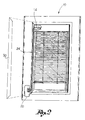
- figure 2 shows a perspective view of a Venetian blind without a glass locking frame
- figure 3 shows a view of a portion of a Venetian blind in a second embodiment thereof, wherein the actuating device is shown excessively enlarged;
- figure 4 shows a cutaway view of a Venetian blind at the level of the electro-motor apparatus
- figure 5 shows the contact holder plate of the actuating system
- figure 6 shows the back side of the control device
- figure 7 shows the front side of the control device
- figure 8 shows a perspective exploded view of the contact holder plate
- figure 9 shows a perspective exploded view of the control device.
- the actuating system of the present invention is advantageously applicable to a Venetian blind with double glazing, that is, a blind wherein the adjustable blades 12 and the relevant moving means are arranged in a sealed air space delimited by two glasses 10'.
- the invention in any case is applicable in the same way to other types of doors or windows, such as roller shutters, provided with a motor driven apparatus for moving the closing means of such doors or windows.
- the system for actuating the Venetian blind 10 comprises an electro-motor apparatus 11 ( Figure 4 ) suitable for moving in an automated manner the rise and the lowering of blades 12 of said Venetian blind.
- the electro-motor apparatus 11 is seated in portion of a frame 13 supporting blind 10.
- the electro-motor apparatus 11 comprises a motor-reduction gear 14 coupled to a roller or shaft 15 for winding/unwinding ropes 12' for moving blades 12.
- Motor-reduction gear 14 and shaft 15 are located in a seat 16 with horizontal extension obtained in a box or a top portion 17 of frame 13 of the blind.
- shaft 15 is associated to a mechanical stop device 18 suitable for stopping the movement of said shaft 15 when the blind reaches a predetermined height position.
- Seat 16 has no further electrical or electronic device for supplying and controlling the electro-motor apparatus 11.
- a contact holder plate 19 is fixed to frame 13 of blind 10, or to one of glasses 10', in any case in a position comfortably accessible by a user, wherein at least two electrical contacts 19' electrically connected to the motor-reduction gear 14 are buried.
- the contact holder plate 19 is suitable for electrically coupling to a control device 20 comprising electrical supply means 22 of the motor-reduction gear 14 and electronic control means 24 of said gear.
- the control device 20 is shaped as a usual remote control, that is, it is a device included in a box shaped container 26 separate from blind 10 and that can be carried by a user.
- the control device 20 is provided with electrical contacts 23 suitable for electrically coupling to the electrical contacts 19' of plate 19 for electrically connecting the supply means and the electronic control means to the electro-motor apparatus 11.
- the contact holder plate 19 is glued to glass 10' ( Figures 3 , 4 ), screwed to frame 13 ( Figure 1 ) or to a simple glass locking frame 30 removably coupled to the frame ( figure 2 ), according to the needs.
- Plate 19 is connected to the motor-reduction gear 14 by electrical conductors 24, for example shaped as a plate, which extend along an external element 25 of the blind frame and which can advantageously be hidden by the glass locking frame 30, so as to be substantially hidden to sight.
- the electrical conductors 24 are associated to suitable sealing means suitable for preventing any air passage between the inside of the air space and the external environment.
- the contact holder plate 19 and the control device 20 can be magnetically coupled to each other so as to obtain the electrical connection between the respective electrical contacts 19', 23.
- the matching between plate 19 and control device 20 that allows establishing an electrical connection between the respective electrical contacts is given by a magnetic field that attracts the control device to the plate.
- the contact holder plate 19 and/or the control device 20 are provided with a magnet suitable for attracting an element made of a ferromagnetic material associated to the control device and/or to the contact holder plate.
- the contact holder plate 19 is provided with two magnets 29 suitable for coupling with corresponding plates of ferromagnetic material 23 associated to the control device 20 and acting as electrical contacts.
- each electrical contact 19' of plate 19 is placed in contact with a respective magnet 29 so as to make a single conductor element therewith.
- magnets 29 have the dual function of coupling means between the control device 20 and plate 19 and electrical conduction means between contacts 23 of the control device and contacts 19' of plate 19. It should be noted that the presence of the electrical contacts 19' is suitable because it would be complicated to connect, for example by welding, the electrical conductors 24 directly to magnets 29.
- the magnetic coupling is such as to overcome the weight force of the control device 20, which remains fixed to plate 19 as soon as it is moved near it, without the need of being manually supported by the user and without the use of further coupling means.
- the ferromagnetic material of plates 23 for example is ferric phosphate.
- the contact holder plate 19 comprises a base 30 suitable for being fixed, for example by a two-faced sheet 31, to the glass or to the frame of the door or window. Two seats 32 are obtained in said base 30, in each there is seated an electrical contact 19' and a magnet 29 superimposed thereto.
- the electrical contacts 19' exhibit a laminar shape and are welded to conductors 24 that protrude from plate 19. Magnets 29 also exhibit a flat shape as a tablet.
- Plate 19 is completed by a cover 33 fixed to base 30, for example by screws 34. At the level of magnets 29, the cover has respective windows 35 wherethrough the outer surface of magnets 29 protrudes, suitable for contacting plates 23 of the control device.
- Plate 19 therefore has a very small thickness, for example in the range of few millimetres. Magnets 29 are almost buried in plate 19, that is, they do not considerably protrude from the front surface of the plate itself
- Base 30 and cover 33 of plate 19 may also be made of plastic material or rubber, for example transparent polycarbonate, so as to hide as much as possible with the frame or the glass.
- plates 23 of the control device 20 have a flat shape so as to not considerably protrude from the box shaped container 26 of the control device 20.
- plates 23 have a contact surface sufficiently wide to allow the immediate centring and thus locking between control device 20 and plate 19.
- the user needs not be careful to the alignment between magnets 29 of plate 19 and plates 23 of the control device; instead, as the user approaches the control device 20 to plate 19, so that the side of the box shaped container 26 carrying plates 23 faces plate 19, the magnetic field force makes the two parts conjugate immediately in a correct manner.
- plates 23 are fixed to the box shaped body 26 of the control device 20 by contact screws 40.
- the contact screws penetrate in said box shaped body 26 and are electrically connected to the power 22 and control 24 means of the motor apparatus.
- said screws 40 are screwed to locking washers 41 that fasten the screws themselves to a pair of electrical cables 42 that connect the electrical contacts 23, 40 to the supply 22 and control 24 means of the motor apparatus provided into the box shaped body 26.
- the power supply means 22 comprise at least one electrical battery, preferably of the rechargeable type.
- the control device is provided with an electrical plug 27 for the connection to a battery charger (not shown).
- the electronic control means 24 comprise:
- the means with self-learning function allow storing a travel end position subsequent to the detection of a current peak due to the activation of the mechanical stop device 18.
- the circuit for detecting the current absorbed is provided for interrupting the supply to the electro-motor apparatus when the absorbed current exceeds a predetermined threshold value.
- control device 20 comprises at least one electrical switch actuable by a user by a key or a button for activating/deactivating an electrical connection between the power supply means and/or the electronic control means of the control device and the electro-motor gear 14.
- a key 28 may be provided for controlling the rise of blind 10 and a key 28' for controlling the lowering of the blind.
- the control device 20 is further provided with light signalling devices 52 for indicating, for example, the correct movement of the blind rising or lowering, or the status of battery 27.
- the actuating system with magnetic coupling allows a user to press a blind rise or lowering key and thanks to the fact that the control device remains autonomously connected to the contact holder plate 19, leaving the control device while the blind is moved, for example for controlling other blinds.
- control device 20 can be disconnected from plate 19, but can also remain connected thereto.
- the actuating system described allows obtaining the following advantages.
- the electronic and supply part is located in a usual box shaped container external to the blind and can be easily fixed in the event of a failure or replaced without intervening on the blind.
- the electrical connection of the electro-motor apparatus to the supply is greatly simplified compared to the current blinds, where electrical conductors to connect to the mains protrude from the blind. There is not the constraint of having to provide an outlet in the proximity of the motor driven blind.
- control device with rechargeable batteries allows avoiding the use of heavy and bulky voltage transformers.
- the blind therefore exhibits the known use comfort of a motor driven movement but is simpler and more expensive to make, reliable over time and in any case easy to maintain.
Abstract
Description
- The present invention relates to the field of doors or windows having motor driven closing means such as for example Venetian blinds, plissé, roller blinds or roller shutter windows, and in particular it refers to an actuating system for such closing means.
- Doors or windows provided with a motor apparatus for moving closing means such as the blades of a Venetian blind are essentially divided in two types, as regards the manufacture of the actuating means and the actuating mode.
- A first type envisages including all the electrical and electronic devices that command and control the motor apparatus in an element of the door or window frame. Only an actuating device is fixed outside the door or window, typically consisting of at least two electrical contacts or switches, that the user must actuate to activate the motor control and command devices in the desired mode.
- A second type envisages the use of a remote control for activating the motor control and command devices. In this case there is the advantage of remotely actuating the means for closing the door or window but it is necessary to include means for transmitting the command signal in the remote control and means for receiving said signal in the door or window.
- In both cases, the command and control devices of the motor apparatus provided in the door or window frame must be connected to the mains to be powered. Since the motor apparatus operates at low voltage, a transformer should further be provided to reduce the mains voltage to the motor operating voltage.
- In the practice, therefore, the electrical system of a room must be designed and modified so as to always be provided with a current outlet in the vicinity of a motor driven door or window.
- In both types mentioned above, moreover, each motor apparatus is associated to its own command and control devices, all integrated in the door or window frame. In the presence of multiple window and door frames, these devices must therefore be multiplied by the number of motor apparatus used.
- In the case of Venetian blinds with double glazing, the motor apparatus and the relevant electrical/electronic devices are located inside a sealed air space. If one of these elements undergoes failure, it is necessary to remove the entire blind and one is often forced to send it to the manufacturer for repair and reassembly.
- In a former patent application n. BS2005A000035 by the same applicant, the limits and the disadvantages mentioned above have been solved by a system for actuating a Venetian blind, a plissé, a roller blind, a roller shutter or similar means for closing a door or window, comprising:
- - an electro-motor apparatus seated in a body or part of a frame of said door or window, without any electrical or electronic power and control device inside said body or frame part,
- - an electrical plug element electrically connected to said electro-motor apparatus and fixed to the door or window in a position accessible by a user, and
- - a command device comprising electrical supply means of the electro-motor apparatus and electronic means to control said apparatus, said command device being transportable by a user and having an electrical outlet element suitable for coupling with said plug element for electrically connecting said supply means and said electronic means for controlling the electro-motor apparatus.
- If, on the one end, such solution allows obtaining clear advantages over the known actuating systems, on the other end it requires the user to make the electrical coupling between plug and outlet each time he/she must move the blind and keep such coupling for all the actuation time. In other words, the user must manually hold the control device while it is connected to the electrical outlet since such device is projecting from the outlet. Moreover, since the electrical outlet must contain the electrical contact suitable for receiving the control device plug, it has a non negligible thickness that could alter the aesthetic appearance of the frame.
- Starting from such premises, the object of the present invention is to obviate the limits and disadvantages mentioned above and propose a system for actuating motor driven doors or windows even more comfortable to use and with very limited overall dimensions.
- Such object is achieved with an actuating system according to
claim 1, with a door or window according toclaim 28 and with a control device according toclaim 31. - The dependent claims describe preferred embodiments.
- Further details and advantages of the actuating system according to the present invention will appear more clearly from the description of a preferred embodiment, made by way of an indicative non-limiting example with reference to the annexed drawings, wherein:
-
figure 1 shows an overall view of a Venetian blind and of a relevant control device according to the present invention; -
figure 2 shows a perspective view of a Venetian blind without a glass locking frame; -
figure 3 shows a view of a portion of a Venetian blind in a second embodiment thereof, wherein the actuating device is shown excessively enlarged; -
figure 4 shows a cutaway view of a Venetian blind at the level of the electro-motor apparatus; -
figure 5 shows the contact holder plate of the actuating system; -
figure 6 shows the back side of the control device; -
figure 7 shows the front side of the control device; -
figure 8 shows a perspective exploded view of the contact holder plate; and -
figure 9 shows a perspective exploded view of the control device. - With the only end of simplifying the description of the present invention, reference shall be made in the following description, in a non-limiting manner, to a system for actuating a Venetian blind 10. In particular, the actuating system of the present invention is advantageously applicable to a Venetian blind with double glazing, that is, a blind wherein the
adjustable blades 12 and the relevant moving means are arranged in a sealed air space delimited by two glasses 10'. - The invention in any case is applicable in the same way to other types of doors or windows, such as roller shutters, provided with a motor driven apparatus for moving the closing means of such doors or windows.
- The system for actuating the Venetian blind 10 comprises an electro-motor apparatus 11 (
Figure 4 ) suitable for moving in an automated manner the rise and the lowering ofblades 12 of said Venetian blind. The electro-motor apparatus 11 is seated in portion of aframe 13 supporting blind 10. Preferably, the electro-motor apparatus 11 comprises a motor-reduction gear 14 coupled to a roller orshaft 15 for winding/unwinding ropes 12' for movingblades 12. - Motor-
reduction gear 14 andshaft 15 are located in aseat 16 with horizontal extension obtained in a box or atop portion 17 offrame 13 of the blind. - According to a preferred embodiment,
shaft 15 is associated to amechanical stop device 18 suitable for stopping the movement of saidshaft 15 when the blind reaches a predetermined height position. - Seat 16 has no further electrical or electronic device for supplying and controlling the electro-
motor apparatus 11. - A
contact holder plate 19 is fixed toframe 13 of blind 10, or to one of glasses 10', in any case in a position comfortably accessible by a user, wherein at least two electrical contacts 19' electrically connected to the motor-reduction gear 14 are buried. - The
contact holder plate 19 is suitable for electrically coupling to acontrol device 20 comprising electrical supply means 22 of the motor-reduction gear 14 and electronic control means 24 of said gear. Thecontrol device 20 is shaped as a usual remote control, that is, it is a device included in a box shapedcontainer 26 separate from blind 10 and that can be carried by a user. Thecontrol device 20 is provided withelectrical contacts 23 suitable for electrically coupling to the electrical contacts 19' ofplate 19 for electrically connecting the supply means and the electronic control means to the electro-motor apparatus 11. - According to an advantageous embodiment, the
contact holder plate 19 is glued to glass 10' (Figures 3 ,4 ), screwed to frame 13 (Figure 1 ) or to a simpleglass locking frame 30 removably coupled to the frame (figure 2 ), according to the needs.Plate 19 is connected to the motor-reduction gear 14 byelectrical conductors 24, for example shaped as a plate, which extend along anexternal element 25 of the blind frame and which can advantageously be hidden by theglass locking frame 30, so as to be substantially hidden to sight. - In the case described herein of the blind with double glazing, the
electrical conductors 24 are associated to suitable sealing means suitable for preventing any air passage between the inside of the air space and the external environment. - According to a general embodiment of the invention, the
contact holder plate 19 and thecontrol device 20 can be magnetically coupled to each other so as to obtain the electrical connection between the respectiveelectrical contacts 19', 23. In other words, the matching betweenplate 19 andcontrol device 20 that allows establishing an electrical connection between the respective electrical contacts is given by a magnetic field that attracts the control device to the plate. - To this end, the
contact holder plate 19 and/or thecontrol device 20 are provided with a magnet suitable for attracting an element made of a ferromagnetic material associated to the control device and/or to the contact holder plate. - According to an embodiment, the
contact holder plate 19 is provided with twomagnets 29 suitable for coupling with corresponding plates offerromagnetic material 23 associated to thecontrol device 20 and acting as electrical contacts. - According to a preferred embodiment, each electrical contact 19' of
plate 19 is placed in contact with arespective magnet 29 so as to make a single conductor element therewith. In other words,magnets 29 have the dual function of coupling means between thecontrol device 20 andplate 19 and electrical conduction means betweencontacts 23 of the control device and contacts 19' ofplate 19. It should be noted that the presence of the electrical contacts 19' is suitable because it would be complicated to connect, for example by welding, theelectrical conductors 24 directly tomagnets 29. - Advantageously, moreover, the magnetic coupling is such as to overcome the weight force of the
control device 20, which remains fixed toplate 19 as soon as it is moved near it, without the need of being manually supported by the user and without the use of further coupling means. - The ferromagnetic material of
plates 23 for example is ferric phosphate. - According to a preferred embodiment, the
contact holder plate 19 comprises abase 30 suitable for being fixed, for example by a two-facedsheet 31, to the glass or to the frame of the door or window. Twoseats 32 are obtained in saidbase 30, in each there is seated an electrical contact 19' and amagnet 29 superimposed thereto. The electrical contacts 19' exhibit a laminar shape and are welded toconductors 24 that protrude fromplate 19.Magnets 29 also exhibit a flat shape as a tablet.Plate 19 is completed by acover 33 fixed tobase 30, for example byscrews 34. At the level ofmagnets 29, the cover hasrespective windows 35 wherethrough the outer surface ofmagnets 29 protrudes, suitable for contactingplates 23 of the control device. -
Plate 19 therefore has a very small thickness, for example in the range of few millimetres.Magnets 29 are almost buried inplate 19, that is, they do not considerably protrude from the front surface of the plate itself -
Base 30 and cover 33 ofplate 19 may also be made of plastic material or rubber, for example transparent polycarbonate, so as to hide as much as possible with the frame or the glass. - Also
plates 23 of thecontrol device 20 have a flat shape so as to not considerably protrude from the box shapedcontainer 26 of thecontrol device 20. - Advantageously, moreover,
plates 23 have a contact surface sufficiently wide to allow the immediate centring and thus locking betweencontrol device 20 andplate 19. In other words, the user needs not be careful to the alignment betweenmagnets 29 ofplate 19 andplates 23 of the control device; instead, as the user approaches thecontrol device 20 to plate 19, so that the side of the box shapedcontainer 26 carryingplates 23 facesplate 19, the magnetic field force makes the two parts conjugate immediately in a correct manner. - According to a preferred embodiment,
plates 23 are fixed to the box shapedbody 26 of thecontrol device 20 by contact screws 40. The contact screws penetrate in said box shapedbody 26 and are electrically connected to thepower 22 andcontrol 24 means of the motor apparatus. For example, said screws 40 are screwed to lockingwashers 41 that fasten the screws themselves to a pair ofelectrical cables 42 that connect theelectrical contacts supply 22 andcontrol 24 means of the motor apparatus provided into the box shapedbody 26. - In one embodiment, the power supply means 22 comprise at least one electrical battery, preferably of the rechargeable type. To this end, the control device is provided with an
electrical plug 27 for the connection to a battery charger (not shown). - According to an advantageous embodiment, the electronic control means 24 comprise:
- - means for controlling the rise and lowering of the blind, allowing the stop thereof in any position;
- - means for controlling a slow movement of the Venetian blind, allowing the blade rotation and thus the light adjustment;
- - at least one circuit for acquiring the position and speed of the motor-
reduction gear 14 and a circuit for detecting the current absorbed by said gear; - - means with self-learning function of the blind position according to the current absorbed by the electro-motor apparatus;
- - means for calibrating the current absorbed by the electro-motor apparatus according to the blind weight and dimensions.
- The means with self-learning function allow storing a travel end position subsequent to the detection of a current peak due to the activation of the
mechanical stop device 18. - The circuit for detecting the current absorbed is provided for interrupting the supply to the electro-motor apparatus when the absorbed current exceeds a predetermined threshold value.
- Advantageously, the
control device 20 comprises at least one electrical switch actuable by a user by a key or a button for activating/deactivating an electrical connection between the power supply means and/or the electronic control means of the control device and the electro-motor gear 14. - For example, a key 28 may be provided for controlling the rise of blind 10 and a key 28' for controlling the lowering of the blind.
- The
control device 20 is further provided with light signalling devices 52 for indicating, for example, the correct movement of the blind rising or lowering, or the status ofbattery 27. - It should be noted that advantageously, the actuating system with magnetic coupling according to the invention allows a user to press a blind rise or lowering key and thanks to the fact that the control device remains autonomously connected to the
contact holder plate 19, leaving the control device while the blind is moved, for example for controlling other blinds. - Once the blind is actuated, the
control device 20 can be disconnected fromplate 19, but can also remain connected thereto. - Besides the above advantages of the magnet coupling system of the invention, the actuating system described allows obtaining the following advantages.
- The elements seated in the blind for its operation are minimised; in the practice, only the electro-motor apparatus is inserted in the blind while all the electronic control circuits thereof are external thereto. This is particularly advantageous in double glazing blinds wherein any failure of a component inside the sealed air space requires full disassembly of the blind and the intervention of skilled personnel.
- The electronic and supply part is located in a usual box shaped container external to the blind and can be easily fixed in the event of a failure or replaced without intervening on the blind.
- The electrical connection of the electro-motor apparatus to the supply is greatly simplified compared to the current blinds, where electrical conductors to connect to the mains protrude from the blind. There is not the constraint of having to provide an outlet in the proximity of the motor driven blind.
- The use of a control device with rechargeable batteries allows avoiding the use of heavy and bulky voltage transformers.
- It is possible to use a
single control device 20 to control multiple electro-motor apparatus of different blinds. In other words, a considerable money and time saving is obtained since for each motor apparatus, the relevant electronic command and control circuits are not provided. - The blind therefore exhibits the known use comfort of a motor driven movement but is simpler and more expensive to make, reliable over time and in any case easy to maintain.
Claims (31)
- System for actuating a Venetian blind, a plissé, a roller blind, a roller shutter or other similar means for closing a door or window, comprising:- an electro-motor apparatus (11) suitable for moving said Venetian blind, shutter or the like, said apparatus being seated in a body (16) or part of a frame of said door or window, and being free from any electrical or electronic power and control device inside said body or frame part,- a contact holder plate (19) fixed to the door or window in a position accessible by a user and comprising at least two electrical contacts (19') electrically connected to said electro-motor apparatus, and- a command device (20) comprising electrical supply means (22) of the electro-motor apparatus and electronic means (24) to control said apparatus, said command device being transportable by a user and having at least two electrical contacts (23) suitable for coupling with the electrical contacts of the contact holder plate for electrically connecting said supply means and said electronic means for controlling the electro-motor apparatus,characterised in that the contact holder plate and the control device are suitable to be magnetically coupled to each other so as to obtain the electrical connection between the respective electrical contacts.
- System according to claim 1, wherein the contact holder plate (19) and/or the control device (20) are provided with at least one magnet (29) suitable for attracting an element made of a ferromagnetic material (23) associated to the control device and/or to the contact holder plate.
- System according to claim 2, wherein the contact holder plate is provided with two magnets (29) suitable for coupling with corresponding plates of ferromagnetic material (23) associated to the control device and acting as electrical contacts.
- System according to claim 3, wherein each electrical contact (19') of the plate is placed in contact with a respective magnet (29) so as to make a single conductor element therewith.
- Actuating system according to claim 4, wherein the contact holder plate (19) comprises a base (30) suitable for being fixed to the glass or to the door or window frame wherein two seats (32) are obtained, in each there is seated an electrical contact (19') and a magnet (29) superimposed thereto.
- System according to claim 5, wherein the electrical contacts (19') have a laminar shape and are welded to respective conductor cables (24) protruding from the plate (19).
- System according to claim 6, wherein the magnets (29) also have a flat shape as a tablet, so as to be substantially buried in the base (30) of the plate (19).
- System according to claim 7, wherein the plate (19) is closed by a cover (33) wherein at the magnets (29) there are obtained respective windows (35) wherethrough the outer surface of the magnets (29) protrudes, suitable for contacting the plates (23) of the control device.
- System according to any one of the previous claims, wherein the magnetic coupling between plate and control device is such as to overcome the weight force of said control device.
- System according to any one of the previous claims, wherein the plate is made of a plastic material or rubber, for example transparent polycarbonate.
- System according to any one of claims 3 to 10, wherein the plates (23) are fixed to the box shaped body of the control device (20) by contact screws (40) that penetrate in said body and are electrically connected to the power (22) and control (24) means of the command device.
- System according to any one of the previous claims, wherein said electro-motor apparatus comprises a motor-reduction gear (14).
- System according to claim 7, wherein said motor-reduction gear is coupled to a roller or shaft (15) for winding/unwinding the Venetian blind, the roller shutter or the like.
- System according to claim 8, wherein said motor-reduction gear is located in a body or seating with horizontal extension obtained in a top portion of the frame of the door or window and wherein the contact holder plate is fixed to a bottom portion of the glass or of the frame of said door or window.
- System according to claim 9, wherein the contact holder plate is glued to a glass or screwed to an element of the frame or fixed to a glass locking frame removably coupled to the frame.
- System according to any one of the previous claims, wherein the contact holder plate is connected to the motor-reduction gear by electrical conductors (24), extending along an external element of the door or window frame and hidden by the glass stopping frame so as to be substantially hidden to sight.
- System according to any one of the previous claims, wherein the door or window is of the double glazing type, and wherein the electrical conductors that connect the contact holder plate to the electro-motor apparatus are associated to sealing means suitable for preventing any air passage between the inside of the air space and the external environment.
- System according to any one of the previous claims, wherein said power supply means comprise at least one electrical battery, for example of the rechargeable type.
- System according to any one of the previous claims, wherein the control device comprises at least one electrical switch actuable by a user by a key or a button for activating/deactivating an electrical connection between the power supply means and/or the electronic control means of the control device and the electro-motor apparatus.
- System according to any one of the previous claims, wherein said electronic control means comprise means for actuating a movement in one direction and in the opposite direction of the blind, roller shutter or the like, allowing the stop thereof in any position.
- System according to any one of the previous claims, wherein said electronic control means comprise means for controlling a slow movement of the Venetian blind, roller shutter or the like, allowing the rotation and the adjustment of the light.
- System according to any one of the previous claims, wherein said electronic control means comprise at least one circuit for acquiring the position and the speed of the electro-motor apparatus and a circuit for detecting the current absorbed by said apparatus.
- System according to claim 17, wherein said circuit for detecting the current absorbed is provided for interrupting the supply to the electro-motor apparatus when the absorbed current exceeds a predetermined threshold value.
- System according to claim 17 or 18, wherein said electronic control means comprise means with self-learning function for the blind position, roller shutter or the like, according to the current absorbed by the electro-motor apparatus.
- System according to any one of the previous claims, wherein the shaft or roller coupled to the electro-motor apparatus is associated to a mechanical stop device (18) suitable for stopping the movement of said shaft when the blind, roller shutter or the like reaches a predetermined position.
- System according to claims 19 and 20, wherein said means with self-learning function allow storing a travel end position subsequent to the detection of a current peak due to the activation of the mechanical stop device.
- System according to any one of the previous claims, wherein said electronic control means comprise means for a calibration of the current absorbed by the electro-motor apparatus based on the weight and the dimensions of the Venetian blind, roller shutter or the like.
- Door or window having a Venetian blind, a roller shutter or similar movable means as closing means, comprising:- an electro-motor apparatus (11) suitable for moving said Venetian blind, shutter or the like, said apparatus being seated in a part of a frame of said door or window, and being free from any electrical or electronic power and control device inside said body or frame part,- an electrical connection element (19) electrically connected to said electro-motor apparatus and fixed to the door or door or window in a position accessible by a user,said electrical connection element being suitable for electrically and magnetically conjugating to a command device that can be carried by a user and comprising means for the power supply of the electro-motor apparatus and electronic means for controlling said apparatus.
- Door or window according to claim 23, wherein said electrical connection element is shaped as a plate wherein at least one magnet (29) is buried.
- Door or window according to claim 24, wherein said magnet also has the function of electrical contact.
- Device for controlling an electro-motor apparatus for moving a Venetian blind, a roller shutter or other movable means for closing a door or window, wherein said electro-motor apparatus is electrically connected to an electrical connection element fixed to the door or door or window in a position accessible by a user, the control device being transportable by a user and comprising means for the electrical supply of the electro-motor apparatus, electronic control means of said apparatus, and electrical and magnetic connection means suitable for electrically and magnetically conjugating to said electrical connection element associated to the door or window.
Priority Applications (2)
| Application Number | Priority Date | Filing Date | Title |
|---|---|---|---|
| SI200730362T SI1936103T1 (en) | 2006-12-13 | 2007-12-06 | System for actuating a roller shutter with a portable control device containing the electric energy supply |
| PL07122510T PL1936103T3 (en) | 2006-12-13 | 2007-12-06 | System for actuating a roller shutter with a portable control device containing the electric energy supply |
Applications Claiming Priority (1)
| Application Number | Priority Date | Filing Date | Title |
|---|---|---|---|
| IT000219A ITBS20060219A1 (en) | 2006-12-13 | 2006-12-13 | SYSTEM OF IMPLEMENTATION OF A VENETIAN BLIND CURTAIN, OF A ROLLER SHUTTER OR OTHER MOVABLE MEANS OF CLOSING A DOOR OR WINDOW |
Publications (3)
| Publication Number | Publication Date |
|---|---|
| EP1936103A2 true EP1936103A2 (en) | 2008-06-25 |
| EP1936103A3 EP1936103A3 (en) | 2009-02-18 |
| EP1936103B1 EP1936103B1 (en) | 2010-07-21 |
Family
ID=39185903
Family Applications (1)
| Application Number | Title | Priority Date | Filing Date |
|---|---|---|---|
| EP07122510A Active EP1936103B1 (en) | 2006-12-13 | 2007-12-06 | System for actuating a roller shutter with a portable control device containing the electric energy supply |
Country Status (8)
| Country | Link |
|---|---|
| EP (1) | EP1936103B1 (en) |
| AT (1) | ATE474993T1 (en) |
| DE (1) | DE602007007878D1 (en) |
| ES (1) | ES2348796T3 (en) |
| IT (1) | ITBS20060219A1 (en) |
| PL (1) | PL1936103T3 (en) |
| PT (1) | PT1936103E (en) |
| SI (1) | SI1936103T1 (en) |
Cited By (7)
| Publication number | Priority date | Publication date | Assignee | Title |
|---|---|---|---|---|
| AU2013100229B4 (en) * | 2009-01-13 | 2013-07-04 | Automatic Technology (Australia) Pty Ltd | Door Operator Unit Having a Motor Unit Housing and an Electric Component Housing |
| WO2013158347A1 (en) * | 2012-04-18 | 2013-10-24 | Homerun Holdings Corporation | Spring tensioned roll type motorized blind or shade system having an external power supply or motor controller |
| EP2700783A1 (en) * | 2012-08-24 | 2014-02-26 | Stylianos KOUPOURTIDIS | Magnetic mechanism for venetian blinds actuation positioned in between double glazing with the use of a small DC electric motor |
| US9241590B2 (en) | 2013-11-18 | 2016-01-26 | Gordon's Window Decor, Inc. | Quick-release control system for architectural opening covering |
| AU2010200132B2 (en) * | 2009-01-13 | 2016-07-07 | Automatic Technology (Australia) Pty Ltd | Door Operator Unit Having a Motor Unit Housing and an Electric Component Housing |
| IT201900015788A1 (en) * | 2019-09-06 | 2021-03-06 | Pellini Spa | Double glazing equipped with a memory module |
| US11957261B2 (en) | 2017-04-28 | 2024-04-16 | Lutron Technology Company Llc | Window treatment mounting bracket |
Families Citing this family (1)
| Publication number | Priority date | Publication date | Assignee | Title |
|---|---|---|---|---|
| US11462871B2 (en) | 2019-10-22 | 2022-10-04 | Hunter Douglas Inc. | Power supply box for use with an architectural-structure covering |
Citations (2)
| Publication number | Priority date | Publication date | Assignee | Title |
|---|---|---|---|---|
| WO2003095781A1 (en) | 2002-05-13 | 2003-11-20 | Ozroll Ip Pty. Ltd. | Improvements to roller shutters |
| US20060076113A1 (en) | 2004-10-12 | 2006-04-13 | Sun Eun Park | Pair glass window and door system equipped with remote controllable auto blind |
Family Cites Families (6)
| Publication number | Priority date | Publication date | Assignee | Title |
|---|---|---|---|---|
| US3810258A (en) * | 1972-07-11 | 1974-05-07 | W Mathauser | Quick connect electrical coupler |
| DE4008939A1 (en) * | 1990-03-20 | 1991-09-26 | Elero Antrieb Sonnenschutz | ELECTRONIC SHUTTER CONTROL WITH PLUG-IN CONTROL |
| WO2002064938A1 (en) * | 2001-02-15 | 2002-08-22 | Alfred Schellenberg Gmbh | Device and method for controlling the strap of a roller blind |
| FR2826517B1 (en) * | 2001-06-20 | 2004-03-12 | Somfy | SUPPLY DEVICE FOR MOTORIZED BLIND OR THE LIKE |
| CN2637690Y (en) * | 2003-07-25 | 2004-09-01 | 亿丰综合工业股份有限公司 | Easy-to-replace cell electric drive curtain |
| US7026789B2 (en) * | 2003-12-23 | 2006-04-11 | Motorola, Inc. | Charging system for electronic devices |
-
2006
- 2006-12-13 IT IT000219A patent/ITBS20060219A1/en unknown
-
2007
- 2007-12-06 PL PL07122510T patent/PL1936103T3/en unknown
- 2007-12-06 AT AT07122510T patent/ATE474993T1/en not_active IP Right Cessation
- 2007-12-06 EP EP07122510A patent/EP1936103B1/en active Active
- 2007-12-06 PT PT07122510T patent/PT1936103E/en unknown
- 2007-12-06 ES ES07122510T patent/ES2348796T3/en active Active
- 2007-12-06 SI SI200730362T patent/SI1936103T1/en unknown
- 2007-12-06 DE DE602007007878T patent/DE602007007878D1/en active Active
Patent Citations (2)
| Publication number | Priority date | Publication date | Assignee | Title |
|---|---|---|---|---|
| WO2003095781A1 (en) | 2002-05-13 | 2003-11-20 | Ozroll Ip Pty. Ltd. | Improvements to roller shutters |
| US20060076113A1 (en) | 2004-10-12 | 2006-04-13 | Sun Eun Park | Pair glass window and door system equipped with remote controllable auto blind |
Cited By (11)
| Publication number | Priority date | Publication date | Assignee | Title |
|---|---|---|---|---|
| AU2013100229B4 (en) * | 2009-01-13 | 2013-07-04 | Automatic Technology (Australia) Pty Ltd | Door Operator Unit Having a Motor Unit Housing and an Electric Component Housing |
| AU2010200132B2 (en) * | 2009-01-13 | 2016-07-07 | Automatic Technology (Australia) Pty Ltd | Door Operator Unit Having a Motor Unit Housing and an Electric Component Housing |
| WO2013158347A1 (en) * | 2012-04-18 | 2013-10-24 | Homerun Holdings Corporation | Spring tensioned roll type motorized blind or shade system having an external power supply or motor controller |
| EP2700783A1 (en) * | 2012-08-24 | 2014-02-26 | Stylianos KOUPOURTIDIS | Magnetic mechanism for venetian blinds actuation positioned in between double glazing with the use of a small DC electric motor |
| US9241590B2 (en) | 2013-11-18 | 2016-01-26 | Gordon's Window Decor, Inc. | Quick-release control system for architectural opening covering |
| US10030443B2 (en) | 2013-11-18 | 2018-07-24 | Gordon's Window Decor, Inc. | Quick-release control system for architectural opening covering |
| US11957261B2 (en) | 2017-04-28 | 2024-04-16 | Lutron Technology Company Llc | Window treatment mounting bracket |
| IT201900015788A1 (en) * | 2019-09-06 | 2021-03-06 | Pellini Spa | Double glazing equipped with a memory module |
| WO2021044226A1 (en) * | 2019-09-06 | 2021-03-11 | Pellini S.P.A. | An insulated glazing unit with a memory module |
| CN114302999A (en) * | 2019-09-06 | 2022-04-08 | 佩利尼股份公司 | Insulating glass unit with memory module |
| IL290676B1 (en) * | 2019-09-06 | 2023-08-01 | Pellini Spa | An insulated glazing unit with a memory module |
Also Published As
| Publication number | Publication date |
|---|---|
| EP1936103B1 (en) | 2010-07-21 |
| EP1936103A3 (en) | 2009-02-18 |
| DE602007007878D1 (en) | 2010-09-02 |
| PT1936103E (en) | 2010-10-21 |
| ES2348796T3 (en) | 2010-12-14 |
| ATE474993T1 (en) | 2010-08-15 |
| ITBS20060219A1 (en) | 2008-06-14 |
| PL1936103T3 (en) | 2010-12-31 |
| SI1936103T1 (en) | 2010-11-30 |
Similar Documents
| Publication | Publication Date | Title |
|---|---|---|
| EP1936103B1 (en) | System for actuating a roller shutter with a portable control device containing the electric energy supply | |
| US20220307321A1 (en) | Motorized window treatment | |
| US9959997B2 (en) | Remote controlled switch cover | |
| US7207142B2 (en) | System and related methods for signaling the position of a movable barrier and securing its position | |
| KR100706328B1 (en) | Apparatus for openning and closing of a slide door | |
| CN101715313A (en) | The automated seat and/or the cover plate assembly that are used for toilet | |
| CN108605394B (en) | Built-in electromechanical device for controlling a device in a building | |
| US8561348B2 (en) | Security automatic garage door closer | |
| US7178291B2 (en) | Automated shutter control | |
| ES2652299T3 (en) | Device for the operation of a remote controllable switch | |
| JP5264617B2 (en) | Winding drive device and winding device | |
| US20070271850A1 (en) | Self-contained motorized lift-slide panel | |
| US20150026890A1 (en) | Emergency power supply device for an electromotive furniture drive for a piece of furniture, electromotive furniture drive, and a corresponding piece of furniture | |
| US20070144684A1 (en) | Door glass assembly with powered blind | |
| AU2020392413A1 (en) | Motorized drive device of an occultation or solar protection device, occultation or solar protection device and associated installation | |
| US4995442A (en) | Curtain opening device | |
| EP0878600A3 (en) | Device driven by an electrical motor for opening a window or a door by a tilting movement | |
| WO2004074620A1 (en) | Winding device | |
| US20220408957A1 (en) | Motorized drive device of an occultation or sunscreen device, occultation or sunscreen device and associated installation | |
| US11713619B2 (en) | Screening device | |
| US20230009409A1 (en) | Electromechanical actuator for blackout or sun-shading device and blackout or sun-shading installation comprising such an actuator | |
| CN110259315B (en) | Motor driving mechanism for door lock | |
| WO2017120010A1 (en) | Remote controlled switch cover | |
| CN210659668U (en) | Motor driving mechanism for door lock | |
| JP4268600B2 (en) | Sliding door opening and closing device |
Legal Events
| Date | Code | Title | Description |
|---|---|---|---|
| PUAI | Public reference made under article 153(3) epc to a published international application that has entered the european phase |
Free format text: ORIGINAL CODE: 0009012 |
|
| AK | Designated contracting states |
Kind code of ref document: A2 Designated state(s): AT BE BG CH CY CZ DE DK EE ES FI FR GB GR HU IE IS IT LI LT LU LV MC MT NL PL PT RO SE SI SK TR |
|
| AX | Request for extension of the european patent |
Extension state: AL BA HR MK RS |
|
| PUAL | Search report despatched |
Free format text: ORIGINAL CODE: 0009013 |
|
| AK | Designated contracting states |
Kind code of ref document: A3 Designated state(s): AT BE BG CH CY CZ DE DK EE ES FI FR GB GR HU IE IS IT LI LT LU LV MC MT NL PL PT RO SE SI SK TR |
|
| AX | Request for extension of the european patent |
Extension state: AL BA HR MK RS |
|
| 17P | Request for examination filed |
Effective date: 20090814 |
|
| 17Q | First examination report despatched |
Effective date: 20090909 |
|
| AKX | Designation fees paid |
Designated state(s): AT BE BG CH CY CZ DE DK EE ES FI FR GB GR HU IE IS IT LI LT LU LV MC MT NL PL PT RO SE SI SK TR |
|
| GRAP | Despatch of communication of intention to grant a patent |
Free format text: ORIGINAL CODE: EPIDOSNIGR1 |
|
| RTI1 | Title (correction) |
Free format text: SYSTEM FOR ACTUATING A ROLLER SHUTTER WITH A PORTABLE CONTROL DEVICE CONTAINING THE ELECTRIC ENERGY SUPPLY |
|
| GRAS | Grant fee paid |
Free format text: ORIGINAL CODE: EPIDOSNIGR3 |
|
| GRAA | (expected) grant |
Free format text: ORIGINAL CODE: 0009210 |
|
| AK | Designated contracting states |
Kind code of ref document: B1 Designated state(s): AT BE BG CH CY CZ DE DK EE ES FI FR GB GR HU IE IS IT LI LT LU LV MC MT NL PL PT RO SE SI SK TR |
|
| REG | Reference to a national code |
Ref country code: GB Ref legal event code: FG4D |
|
| REG | Reference to a national code |
Ref country code: CH Ref legal event code: EP |
|
| REG | Reference to a national code |
Ref country code: IE Ref legal event code: FG4D |
|
| REF | Corresponds to: |
Ref document number: 602007007878 Country of ref document: DE Date of ref document: 20100902 Kind code of ref document: P |
|
| REG | Reference to a national code |
Ref country code: GR Ref legal event code: EP Ref document number: 20100402020 Country of ref document: GR |
|
| REG | Reference to a national code |
Ref country code: RO Ref legal event code: EPE |
|
| REG | Reference to a national code |
Ref country code: NL Ref legal event code: T3 |
|
| REG | Reference to a national code |
Ref country code: ES Ref legal event code: FG2A Effective date: 20101130 |
|
| LTIE | Lt: invalidation of european patent or patent extension |
Effective date: 20100721 |
|
| REG | Reference to a national code |
Ref country code: PL Ref legal event code: T3 |
|
| PG25 | Lapsed in a contracting state [announced via postgrant information from national office to epo] |
Ref country code: LT Free format text: LAPSE BECAUSE OF FAILURE TO SUBMIT A TRANSLATION OF THE DESCRIPTION OR TO PAY THE FEE WITHIN THE PRESCRIBED TIME-LIMIT Effective date: 20100721 Ref country code: AT Free format text: LAPSE BECAUSE OF FAILURE TO SUBMIT A TRANSLATION OF THE DESCRIPTION OR TO PAY THE FEE WITHIN THE PRESCRIBED TIME-LIMIT Effective date: 20100721 Ref country code: FI Free format text: LAPSE BECAUSE OF FAILURE TO SUBMIT A TRANSLATION OF THE DESCRIPTION OR TO PAY THE FEE WITHIN THE PRESCRIBED TIME-LIMIT Effective date: 20100721 |
|
| PG25 | Lapsed in a contracting state [announced via postgrant information from national office to epo] |
Ref country code: IS Free format text: LAPSE BECAUSE OF FAILURE TO SUBMIT A TRANSLATION OF THE DESCRIPTION OR TO PAY THE FEE WITHIN THE PRESCRIBED TIME-LIMIT Effective date: 20101121 Ref country code: CY Free format text: LAPSE BECAUSE OF FAILURE TO SUBMIT A TRANSLATION OF THE DESCRIPTION OR TO PAY THE FEE WITHIN THE PRESCRIBED TIME-LIMIT Effective date: 20100721 |
|
| REG | Reference to a national code |
Ref country code: HU Ref legal event code: AG4A Ref document number: E009037 Country of ref document: HU |
|
| REG | Reference to a national code |
Ref country code: SK Ref legal event code: T3 Ref document number: E 8344 Country of ref document: SK |
|
| PG25 | Lapsed in a contracting state [announced via postgrant information from national office to epo] |
Ref country code: BE Free format text: LAPSE BECAUSE OF FAILURE TO SUBMIT A TRANSLATION OF THE DESCRIPTION OR TO PAY THE FEE WITHIN THE PRESCRIBED TIME-LIMIT Effective date: 20100721 Ref country code: LV Free format text: LAPSE BECAUSE OF FAILURE TO SUBMIT A TRANSLATION OF THE DESCRIPTION OR TO PAY THE FEE WITHIN THE PRESCRIBED TIME-LIMIT Effective date: 20100721 Ref country code: SE Free format text: LAPSE BECAUSE OF FAILURE TO SUBMIT A TRANSLATION OF THE DESCRIPTION OR TO PAY THE FEE WITHIN THE PRESCRIBED TIME-LIMIT Effective date: 20100721 |
|
| PG25 | Lapsed in a contracting state [announced via postgrant information from national office to epo] |
Ref country code: DK Free format text: LAPSE BECAUSE OF FAILURE TO SUBMIT A TRANSLATION OF THE DESCRIPTION OR TO PAY THE FEE WITHIN THE PRESCRIBED TIME-LIMIT Effective date: 20100721 |
|
| PLBE | No opposition filed within time limit |
Free format text: ORIGINAL CODE: 0009261 |
|
| STAA | Information on the status of an ep patent application or granted ep patent |
Free format text: STATUS: NO OPPOSITION FILED WITHIN TIME LIMIT |
|
| PG25 | Lapsed in a contracting state [announced via postgrant information from national office to epo] |
Ref country code: EE Free format text: LAPSE BECAUSE OF FAILURE TO SUBMIT A TRANSLATION OF THE DESCRIPTION OR TO PAY THE FEE WITHIN THE PRESCRIBED TIME-LIMIT Effective date: 20100721 |
|
| 26N | No opposition filed |
Effective date: 20110426 |
|
| REG | Reference to a national code |
Ref country code: DE Ref legal event code: R097 Ref document number: 602007007878 Country of ref document: DE Effective date: 20110426 |
|
| PG25 | Lapsed in a contracting state [announced via postgrant information from national office to epo] |
Ref country code: IE Free format text: LAPSE BECAUSE OF NON-PAYMENT OF DUE FEES Effective date: 20101206 |
|
| PG25 | Lapsed in a contracting state [announced via postgrant information from national office to epo] |
Ref country code: IT Free format text: LAPSE BECAUSE OF NON-PAYMENT OF DUE FEES Effective date: 20101206 Ref country code: MT Free format text: LAPSE BECAUSE OF FAILURE TO SUBMIT A TRANSLATION OF THE DESCRIPTION OR TO PAY THE FEE WITHIN THE PRESCRIBED TIME-LIMIT Effective date: 20100721 |
|
| REG | Reference to a national code |
Ref country code: CH Ref legal event code: PL |
|
| PG25 | Lapsed in a contracting state [announced via postgrant information from national office to epo] |
Ref country code: LU Free format text: LAPSE BECAUSE OF NON-PAYMENT OF DUE FEES Effective date: 20101206 |
|
| PG25 | Lapsed in a contracting state [announced via postgrant information from national office to epo] |
Ref country code: CH Free format text: LAPSE BECAUSE OF NON-PAYMENT OF DUE FEES Effective date: 20111231 Ref country code: LI Free format text: LAPSE BECAUSE OF NON-PAYMENT OF DUE FEES Effective date: 20111231 |
|
| REG | Reference to a national code |
Ref country code: FR Ref legal event code: PLFP Year of fee payment: 9 |
|
| REG | Reference to a national code |
Ref country code: FR Ref legal event code: PLFP Year of fee payment: 10 |
|
| REG | Reference to a national code |
Ref country code: FR Ref legal event code: PLFP Year of fee payment: 11 |
|
| PGFP | Annual fee paid to national office [announced via postgrant information from national office to epo] |
Ref country code: PL Payment date: 20221021 Year of fee payment: 16 |
|
| PGFP | Annual fee paid to national office [announced via postgrant information from national office to epo] |
Ref country code: ES Payment date: 20230102 Year of fee payment: 16 |
|
| P01 | Opt-out of the competence of the unified patent court (upc) registered |
Effective date: 20230508 |
|
| PGFP | Annual fee paid to national office [announced via postgrant information from national office to epo] |
Ref country code: SK Payment date: 20231129 Year of fee payment: 17 |
|
| PGFP | Annual fee paid to national office [announced via postgrant information from national office to epo] |
Ref country code: GR Payment date: 20231221 Year of fee payment: 17 Ref country code: GB Payment date: 20231220 Year of fee payment: 17 |
|
| PGFP | Annual fee paid to national office [announced via postgrant information from national office to epo] |
Ref country code: MC Payment date: 20231222 Year of fee payment: 17 |
|
| PGFP | Annual fee paid to national office [announced via postgrant information from national office to epo] |
Ref country code: TR Payment date: 20231204 Year of fee payment: 17 Ref country code: SI Payment date: 20231123 Year of fee payment: 17 Ref country code: RO Payment date: 20231129 Year of fee payment: 17 Ref country code: PT Payment date: 20231123 Year of fee payment: 17 Ref country code: NL Payment date: 20231226 Year of fee payment: 17 Ref country code: IT Payment date: 20231006 Year of fee payment: 17 Ref country code: HU Payment date: 20231222 Year of fee payment: 17 Ref country code: FR Payment date: 20231220 Year of fee payment: 17 Ref country code: DE Payment date: 20231214 Year of fee payment: 17 Ref country code: CZ Payment date: 20231024 Year of fee payment: 17 Ref country code: BG Payment date: 20231106 Year of fee payment: 17 |
|
| PGFP | Annual fee paid to national office [announced via postgrant information from national office to epo] |
Ref country code: PL Payment date: 20231024 Year of fee payment: 17 |
|
| PGFP | Annual fee paid to national office [announced via postgrant information from national office to epo] |
Ref country code: ES Payment date: 20240102 Year of fee payment: 17 |