EP1938758A2 - Endoscopic treatment tool and suturing method using the same - Google Patents
Endoscopic treatment tool and suturing method using the same Download PDFInfo
- Publication number
- EP1938758A2 EP1938758A2 EP07025056A EP07025056A EP1938758A2 EP 1938758 A2 EP1938758 A2 EP 1938758A2 EP 07025056 A EP07025056 A EP 07025056A EP 07025056 A EP07025056 A EP 07025056A EP 1938758 A2 EP1938758 A2 EP 1938758A2
- Authority
- EP
- European Patent Office
- Prior art keywords
- hollow organ
- suturing
- tubular body
- treatment tool
- stomach
- Prior art date
- Legal status (The legal status is an assumption and is not a legal conclusion. Google has not performed a legal analysis and makes no representation as to the accuracy of the status listed.)
- Granted
Links
Images


Classifications
-
- A—HUMAN NECESSITIES
- A61—MEDICAL OR VETERINARY SCIENCE; HYGIENE
- A61B—DIAGNOSIS; SURGERY; IDENTIFICATION
- A61B17/00—Surgical instruments, devices or methods, e.g. tourniquets
- A61B17/04—Surgical instruments, devices or methods, e.g. tourniquets for suturing wounds; Holders or packages for needles or suture materials
- A61B17/0469—Suturing instruments for use in minimally invasive surgery, e.g. endoscopic surgery
-
- A—HUMAN NECESSITIES
- A61—MEDICAL OR VETERINARY SCIENCE; HYGIENE
- A61B—DIAGNOSIS; SURGERY; IDENTIFICATION
- A61B17/00—Surgical instruments, devices or methods, e.g. tourniquets
- A61B17/00234—Surgical instruments, devices or methods, e.g. tourniquets for minimally invasive surgery
-
- A—HUMAN NECESSITIES
- A61—MEDICAL OR VETERINARY SCIENCE; HYGIENE
- A61B—DIAGNOSIS; SURGERY; IDENTIFICATION
- A61B17/00—Surgical instruments, devices or methods, e.g. tourniquets
- A61B17/04—Surgical instruments, devices or methods, e.g. tourniquets for suturing wounds; Holders or packages for needles or suture materials
- A61B17/0482—Needle or suture guides
-
- A—HUMAN NECESSITIES
- A61—MEDICAL OR VETERINARY SCIENCE; HYGIENE
- A61B—DIAGNOSIS; SURGERY; IDENTIFICATION
- A61B17/00—Surgical instruments, devices or methods, e.g. tourniquets
- A61B17/04—Surgical instruments, devices or methods, e.g. tourniquets for suturing wounds; Holders or packages for needles or suture materials
- A61B17/06—Needles ; Sutures; Needle-suture combinations; Holders or packages for needles or suture materials
- A61B17/062—Needle manipulators
- A61B17/0625—Needle manipulators the needle being specially adapted to interact with the manipulator, e.g. being ridged to snap fit in a hole of the manipulator
-
- A—HUMAN NECESSITIES
- A61—MEDICAL OR VETERINARY SCIENCE; HYGIENE
- A61B—DIAGNOSIS; SURGERY; IDENTIFICATION
- A61B17/00—Surgical instruments, devices or methods, e.g. tourniquets
- A61B17/11—Surgical instruments, devices or methods, e.g. tourniquets for performing anastomosis; Buttons for anastomosis
- A61B17/1114—Surgical instruments, devices or methods, e.g. tourniquets for performing anastomosis; Buttons for anastomosis of the digestive tract, e.g. bowels or oesophagus
-
- A—HUMAN NECESSITIES
- A61—MEDICAL OR VETERINARY SCIENCE; HYGIENE
- A61B—DIAGNOSIS; SURGERY; IDENTIFICATION
- A61B17/00—Surgical instruments, devices or methods, e.g. tourniquets
- A61B17/04—Surgical instruments, devices or methods, e.g. tourniquets for suturing wounds; Holders or packages for needles or suture materials
- A61B17/06—Needles ; Sutures; Needle-suture combinations; Holders or packages for needles or suture materials
- A61B17/06066—Needles, e.g. needle tip configurations
-
- A—HUMAN NECESSITIES
- A61—MEDICAL OR VETERINARY SCIENCE; HYGIENE
- A61B—DIAGNOSIS; SURGERY; IDENTIFICATION
- A61B18/00—Surgical instruments, devices or methods for transferring non-mechanical forms of energy to or from the body
- A61B18/04—Surgical instruments, devices or methods for transferring non-mechanical forms of energy to or from the body by heating
- A61B18/12—Surgical instruments, devices or methods for transferring non-mechanical forms of energy to or from the body by heating by passing a current through the tissue to be heated, e.g. high-frequency current
- A61B18/14—Probes or electrodes therefor
- A61B18/1492—Probes or electrodes therefor having a flexible, catheter-like structure, e.g. for heart ablation
-
- A—HUMAN NECESSITIES
- A61—MEDICAL OR VETERINARY SCIENCE; HYGIENE
- A61B—DIAGNOSIS; SURGERY; IDENTIFICATION
- A61B17/00—Surgical instruments, devices or methods, e.g. tourniquets
- A61B2017/00535—Surgical instruments, devices or methods, e.g. tourniquets pneumatically or hydraulically operated
- A61B2017/00539—Surgical instruments, devices or methods, e.g. tourniquets pneumatically or hydraulically operated hydraulically
-
- A—HUMAN NECESSITIES
- A61—MEDICAL OR VETERINARY SCIENCE; HYGIENE
- A61B—DIAGNOSIS; SURGERY; IDENTIFICATION
- A61B17/00—Surgical instruments, devices or methods, e.g. tourniquets
- A61B2017/00535—Surgical instruments, devices or methods, e.g. tourniquets pneumatically or hydraulically operated
- A61B2017/00557—Surgical instruments, devices or methods, e.g. tourniquets pneumatically or hydraulically operated inflatable
-
- A—HUMAN NECESSITIES
- A61—MEDICAL OR VETERINARY SCIENCE; HYGIENE
- A61B—DIAGNOSIS; SURGERY; IDENTIFICATION
- A61B17/00—Surgical instruments, devices or methods, e.g. tourniquets
- A61B2017/00743—Type of operation; Specification of treatment sites
- A61B2017/00818—Treatment of the gastro-intestinal system
- A61B2017/00827—Treatment of gastro-esophageal reflux
-
- A—HUMAN NECESSITIES
- A61—MEDICAL OR VETERINARY SCIENCE; HYGIENE
- A61B—DIAGNOSIS; SURGERY; IDENTIFICATION
- A61B17/00—Surgical instruments, devices or methods, e.g. tourniquets
- A61B2017/00831—Material properties
- A61B2017/00867—Material properties shape memory effect
-
- A—HUMAN NECESSITIES
- A61—MEDICAL OR VETERINARY SCIENCE; HYGIENE
- A61B—DIAGNOSIS; SURGERY; IDENTIFICATION
- A61B17/00—Surgical instruments, devices or methods, e.g. tourniquets
- A61B17/30—Surgical pincettes without pivotal connections
- A61B2017/306—Surgical pincettes without pivotal connections holding by means of suction
-
- A—HUMAN NECESSITIES
- A61—MEDICAL OR VETERINARY SCIENCE; HYGIENE
- A61B—DIAGNOSIS; SURGERY; IDENTIFICATION
- A61B18/00—Surgical instruments, devices or methods for transferring non-mechanical forms of energy to or from the body
- A61B2018/00315—Surgical instruments, devices or methods for transferring non-mechanical forms of energy to or from the body for treatment of particular body parts
- A61B2018/00482—Digestive system
-
- A—HUMAN NECESSITIES
- A61—MEDICAL OR VETERINARY SCIENCE; HYGIENE
- A61B—DIAGNOSIS; SURGERY; IDENTIFICATION
- A61B18/00—Surgical instruments, devices or methods for transferring non-mechanical forms of energy to or from the body
- A61B18/04—Surgical instruments, devices or methods for transferring non-mechanical forms of energy to or from the body by heating
- A61B18/12—Surgical instruments, devices or methods for transferring non-mechanical forms of energy to or from the body by heating by passing a current through the tissue to be heated, e.g. high-frequency current
- A61B18/14—Probes or electrodes therefor
- A61B2018/1475—Electrodes retractable in or deployable from a housing
-
- A—HUMAN NECESSITIES
- A61—MEDICAL OR VETERINARY SCIENCE; HYGIENE
- A61B—DIAGNOSIS; SURGERY; IDENTIFICATION
- A61B18/00—Surgical instruments, devices or methods for transferring non-mechanical forms of energy to or from the body
- A61B18/04—Surgical instruments, devices or methods for transferring non-mechanical forms of energy to or from the body by heating
- A61B18/12—Surgical instruments, devices or methods for transferring non-mechanical forms of energy to or from the body by heating by passing a current through the tissue to be heated, e.g. high-frequency current
- A61B18/14—Probes or electrodes therefor
- A61B2018/1495—Electrodes being detachable from a support structure
-
- A—HUMAN NECESSITIES
- A61—MEDICAL OR VETERINARY SCIENCE; HYGIENE
- A61B—DIAGNOSIS; SURGERY; IDENTIFICATION
- A61B18/00—Surgical instruments, devices or methods for transferring non-mechanical forms of energy to or from the body
- A61B18/04—Surgical instruments, devices or methods for transferring non-mechanical forms of energy to or from the body by heating
- A61B18/12—Surgical instruments, devices or methods for transferring non-mechanical forms of energy to or from the body by heating by passing a current through the tissue to be heated, e.g. high-frequency current
- A61B18/14—Probes or electrodes therefor
- A61B2018/1497—Electrodes covering only part of the probe circumference
Definitions
- the present invention relates to an endoscopic treatment tool and suturing method using the same.
- An object of this invention is to provide an endoscopic treatment tool and suturing methods using the same, that can suture the inside wall of hollow organs into a tubular shape with desirable diameters via a natural orifice.
- An endoscopic treatment tool is an endoscopic treatment tool which is inserted into a hollow organ via a natural orifice and performs a suturing procedure within the hollow organ or abdominal cavities, includes a hollow organ lining support which is smaller than the smallest diameter of a passage from the natural orifice to the hollow organ, a portion of the hollow organ lining support being able to expand so as to have a diameter larger than the smallest diameter of the passage from the natural orifice to the hollow organ.
- a high-frequency treatment tool is a high-frequency treatment tool which is inserted into a hollow organ via a natural orifice, and performs a suturing procedure within the hollow organs or abdominal cavities, includes a high-frequency electrode which is inserted into an instrument channel of the endoscope so as to freely protrude and retract, and high-frequency electricity is applied.
- a high-frequency treatment tool is a high-frequency treatment tool which is inserted into a hollow organ via a natural orifice and perform a suturing procedure within the hollow organ or abdominal cavities, includes a cap which is detachably disposed at a distal end of an endoscope, and a high-frequency electrode in which a high-frequency electricity is applied thereto is disposed on the cap.
- a suturing method is a suturing method using a high-frequency treatment tool which is inserted into a hollow organ via a natural orifice and performs a suturing procedure of suturing the hollow organ lining, including the steps of; inserting a hollow organ lining support provided on the endscopic treatment tool, which is smaller than the smallest diameter of a passage from the natural orifice to the hollow organ, a portion of the hollow organ lining support being able to expand so as to have a diameter larger than the smallest diameter of the passage from the natural orifice to the hollow organ; expanding at least a portion of the hollow organ lining support within the hollow organ; and suturing the hollow organ lining into a tubular shape.
- a suturing tool as an endoscopic treatment tool 1 is a suturing tool which is inserted into a stomach (hollow organ) via the mouth, nose, anus or other natural orifice, and performs a suturing treatment inside of the stomach or abdominal cavity.
- the suturing tool 1 includes a hollow organ lining support 2 (herein after abbreviated as a stomach wall support) which is smaller than the smallest diameter of a passage from the natural orifice to the hollow organ, a portion of the hollow organ lining support being able to expand so as to have a diameter larger than the smallest diameter of a diameter of cardia of stomach, in other words, the passage from the natural orifice to the hollow organ; and an inner tube 3 which connects to a tubular body 2A which is described later, of the stomach wall support 2.
- a hollow organ lining support 2 herein after abbreviated as a stomach wall support
- the stomach wall support 2 includes the tubular body 2A including fine threads 2a netted into a cylindrical shape and a lateral face thereof is covered with a film 2b, and a distal end portion 2B consisted of fine threads 2a netted to cover the distal end open portion of the tubular body 2A and is also covered with the film 2b.
- a pair of plates 5A provided with a window (open portion) 5A thereon are disposed on the lateral face of the tubular body 2A symmetrically with respect to the central axis C.
- the number of window 5A is not limited thereto. One or a plurality of windows may be provided.
- a proximal end of the tubular body 2A is connected to the inner tube 3.
- the tubular body 2A accommodates a suturing needle not illustrated.
- the tubular body 2A also includes an aspiration lumen 6 connected to an aspirator (not illustrated).
- the 2B is disposed to cover the distal opening of the tubular body 2A, and an opening 6A of the aspiration lumen 6 is disposed on a center thereof.
- the distal end portion 2B Upon compression of the tubular body 2A, the distal end portion 2B is compressed such that the center is projected out to the distal end.
- the distal end portion 2B Upon dilation of the tubular body 2A, the distal end portion 2B is dilated so as to deform into a plane.
- the stomach wall support 2 is inserted into the overtube OT in which the outer diameter has a substantially same diameter as an inner diameter of the cardia CA, in a compressed state.
- the distal end of the overtube OT generates various curved movements with an operation of a curved knob N disposed at a proximal end of the overtube OT.
- An outer diameter of the inner tube 3 has a diameter substantially equal to an outer diameter of the compressed state of the tubular body 2A.
- An operation knob 7 which operates a suturing needle (a suturing tool) housed in the tubular body 2A is provided at the proximal end thereof.
- An insertion opening 3A of the endoscope E is provided at a distal end of the inner tube 3.
- An aspiration opening 3B which is connected to a distal end of the aspiration lumen 6 is disposed in the vicinity of the insertion opening 3A.
- the suturing procedure according to the present embodiment consists of an insertion step (S01) of inserting the overtube OT containing the stomach wall support 2, into the stomach S via the mouth of the patient; a distending step (S20) in which the diameter of the stomach wall support 2 is expanded within the stomach S; and a suturing step (S03) of suturing a stomach wall SW from the cardia CA to a pylorus PY into a tubular shape.
- the insertion step (S01) is performed by inserting the overtube OT accommodating the stomach wall support 2 and the inner tube 3 therein, into in the vicinity of the cardia CA of the stomach S via the mouth of the patient. At this time, the stomach wall support 2 is in a compressed status into an inner radial direction pressed by the overtube OT.
- the distending step is performed by shifting the overtube OT to a proximal side relative to the inner tube 3 so as to expose the stomach wall support 2.
- the stomach wall support 2 is released from the OT compressing the lateral face of the stomach wall support 2 into the radial direction, and the diameter of the stomach wall support 2 expands to its original outer diameter size which is larger than the diameter of the cardia CA as shown in FIG 3 .
- the distal end portion 2B is also deformed into a flat plane after expansion of the diameter.
- the suturing step (S03) is performed by aspirating the stomach S by the aspiration lumen 6 accompanying the unshown aspirator, and the stomach S is contracted.
- the stomach wall SW attaches onto the stomach wall support 2.
- a part of the stomach wall SW is pulled into the windows 5A so as to aspirate the stomach wall SW, resulting the formation of a tubular section having a diameter larger than the inner diameter of the cardia CA within the stomach S by the stomach wall support 2.
- the stomach wall SW pulled into the windows 5A is later sutured by the suturing needle not illustrated.
- Suturing is performed by moving the inner tube 3 or by moving the overtube OT in conjunction with the movement of the inner tube 3 accompanying the overtube OT, so that stitches ST are lined up along a lesser curvature LC from the cardia CA to the pylorus PY of the stomach S as shown in FIG. 4 .
- suturing from the cardia CA to the pylorus PY may be performed by; suturing in a straight line from the lesser curvature LC to the vicinity of a greater curvature GC of the stomach (but not suturing all the way to the GC); then suturing in a straight line from the greater curvature GC to the vicinity of the lesser curvature LC (but not suturing all the way to the lesser curvature LC) from the pylorus PY side at a predetermined distance away.
- This suturing method may be repeated in sequence a plurality of times so that stitches reach the vicinity of the pylorus PY.
- suturing may be performed so as to clinch a fundus of stomach FS as shown in FIGS. 6 and 7 , or without such clinching as shown in FIGS. 8 and 9 .
- the inner tube 3 is moved with respect to the overtube OT, so that the stomach wall support 2 is received by being compressed into the overtube OT. Once the stomach wall support 2 is completely received inside of the overtube OT, the entire suturing tool 1 and the overtube OT are drawn out from the mouth of the patient.
- the tubular section in which the inner diameter is larger than the inner diameter of the cardia CA can be formed within the stomach S by virtue of a provision of the stomach wall support 2 then sutured into the tubular section by expansion of the stomach wall support 2 within the stomach S.
- the windows 5A are disposed on the stomach wall support 2
- suturing with the unshown suturing needle can be performed via the windows 5A.
- the stomach wall support 2 is provided with the overtube OT which freely advances and retracts with respect to the stomach wall support 2, thereby the size of the stomach wall support 2 can be adjusted according to a protrusion or recession amount of the stomach wall support 2 from the overtube OT.
- the second embodiment differs from the first embodiment in that a tubular body 11 of a suturing tool 10 in the present embodiment is a rigid body being able to pass through the cardia CA of the stomach S, and a stomach wall support 12 is disposed as a part of a lateral face of the tubular body 11, so as to protrude and retract with respect to the tubular body 11.
- An opening portion 13 is provided on the lateral face of the tubular body 11 for the stomach wall support 12 being able to protrude and retract with respect to the tubular body 11.
- a suturing tool 10 includes a transfer mechanism 15 which makes the stomach wall support 12 protrude and retract with respect to the opening portion 13 in a radial direction (normal line direction to the opening portion 13).
- the transfer mechanism 15 is the rigid body and includes an operation wire 15A in which the distal end is fixed to the tubular body 11.
- a proximal end of the operation wire 15A extends to an operation section proximal to an operator.
- a proximal end of the tubular body 11 is connected to the inner tube 3.
- the stomach wall support 12 is surrounded by an outer lateral face 12a, an inner lateral face 12b, and a pair of aspiration faces 12c; the outer lateral face 12a which is a part of the lateral face of the tubular body 11, the inner lateral face 12b which comes into contact with an inner lateral face of the tubular body 11 which is symmetrical to the opening portion 13 and a pair of aspiration faces 12c in which a pair of windows 16 where stomach wall SW is aspirated into are provided on both aspiration faces 12c.
- a pair of high-frequency electrodes 17 is provided on an inner side of the outer lateral face 12a in order to cauterize the stomach wall SW aspirated from the windows 16.
- the high-frequency electrodes 17 are connected to an operation section proximal to the operator not illustrated via the operation wire 15A, the high-frequency electrodes 17 are moved to the tubular body 11 side by crossing through the window 16 upon pulling the operation wire 15A by the operation of the operation section.
- the inner lateral face 12b is in arc-shape formed along the shape of the inner lateral face of the tubular body 11. Since the surface area of the arc-shape of the inner lateral face 12b is larger than the opened area of the opening portion 13, the inner lateral face 12b is detained inside of the tubular body 11.
- the pair of windows 16 are disposed so as to oppose each other, in a direction perpendicular to the central axis C.
- An axis 18A which is connected to an operation knob is provided in the stomach wall support 12 along the inner lateral face 12b and the outer lateral face 12a of the stomach wall support 12.
- a plurality of ringshaped suturing needles 18B are disposed with a predetermined distance apart from each other around the axis 18A as the center of the needles 18B.
- the suturing procedure according to the present embodiment consists of an insertion step (S11) of inserting the overtube OT provided with the stomach wall support 12 into the stomach S via the mouth of the patient; a distending step (S12) in which the stomach wall support 12 is projected out from the tubular body 11 within the stomach S; and a suturing step (S13) of suturing the stomach wall SW from the cardia CA to the pylorus PY into a tubular shape.
- the insertion step (S11) of inserting the overtube OT provided with the tubular body 11 and the stomach wall support 12 in a state in which the stomach wall support 12 is housed inside of the tubular body 11, into the vicinity of the cardia CA of the stomach S via the mouth of the patient is performed.
- the distending step (S 12) is performed by pulling the operation wire 15A with an operation of the transfer mechanism 15.
- the stomach wall support 12 moves until the inner lateral face 12b comes into a contact with the window 16 of the tubular body 11 so as to expose the window 16 of the stomach wall support 12 from the inside of the tubular body 11 to the outside thereof.
- the suturing step (S13) is performed by aspirating the stomach S by the aspirator not illustrated, and the stomach S is contracted.
- the stomach wall SW attaches to the stomach wall support 12.
- stomach wall support 12 By reducing the internal pressure of the stomach wall support 12 compared to a pressure of the stomach S, a part of the stomach wall SW is pulled into the windows 16 so as to aspirate the stomach wall SW, resulting a formation of a tubular section having a diameter larger than the inner diameter of the cardia CA within the stomach S by the stomach wall support 12.
- the high-frequency electrodes 17 moves to the tubular body 11 side by crossing through the window 16 by incising or cauterizing a mucous of the stomach wall SW, thereby promoting coalescence after the suturing treatment.
- the stomach wall SW is then sutured by suturing needles 18B with a rotation of the axis 18A by an operation on an operation knob.
- the transfer mechanism 15 Upon completion of suturing, the transfer mechanism 15 is operated again and the stomach wall support 12 is pulled into the tubular body 11 by pulling the operation wire 15A so that the outer lateral face 12a is returned to the same plane as the lateral face of the tubular body 11. Then the entire suturing tool 10 is drawn out from the mouth of the patient.
- the third embodiment differs from the second embodiment in that a stomach wall support 21 of a suturing tool 20 according to the present embodiment is pivotally mounted on a pivot support pin 25 as a part of a lateral face of a tubular body 22 so as to be detachably mounted to a window 23 formed on a tubular body 22.
- Both of the axis 18A and the suturing needles 18B are housed inside of the tubular body 22 in a position where the suturing needles 18B can pierce the stomach wall SW aspirated from a window 23.
- the window 23 is formed in a substantially rectangular shape in plan view along the central axis C as the longitudinal direction.
- the stomach wall support 21 is also formed in a substantially rectangular shape in plan view along the central axis C as the longitudinal direction so as to cover the window 23.
- a distal end 21a of the stomach wall support 21 is pivotally mounted about the pivot support pin 25 which elongates to a direction crossing with the central axis C so as to freely rotate about the pivot support pin 25.
- the stomach wall support 21 is formed in the same curved-shape as the lateral face of the tubular body 22 and is provided with an outer lateral face 21b on the outer peripheral side and an inner lateral face 21c on the inner peripheral side of the stomach wall support 21.
- the stomach wall support 21 is rotated by a transfer mechanism not illustrated.
- the suturing procedure according to the present embodiment includes an insertion step (S21) of inserting the overtube OT provided with the stomach wall support 21 into the stomach S via the mouth of the patient; a distending step (S22) in which the tubular body 22 is projected out within the stomach S; and a suturing step (S23) of suturing a stomach wall SW from the cardia CA to the pylorus PY of the stomach S into a tubular shape.
- the insertion step (S21) of inserting the stomach wall support 21 in a state in which the stomach wall support 21 is closed so as to cover the window 23 of the tubular body 22, into the vicinity of the cardia CA of the stomach S via the mouth of the patient is performed.
- the distending step (S22) is performed by pivoting the stomach wall support 21 about the pivot support pin 25, so that a proximal end 21d of the stomach wall support 21 moves away from the tubular body 22, and the window 23 of the stomach wall support 21 is exposed.
- the suturing step (S23) is performed by aspirating the stomach S by the aspirator (not illustrated), and the stomach S is contracted.
- the stomach wall SW attaches to both sides of the stomach wall support 21 (i.e., the outer lateral face 21b and the inner lateral face 21c as shown in FIG. 16 ), resulting in the formation of a tubular section having a diameter larger than the inner diameter of the cardia CA within the stomach S by the tubular body 22.
- the tubular body 22 may be disposed on any position along the overtube OT' as shown in FIG 17 , and is not limited to being disposed on the distal end of the tubular body 22.
- the window 23 of a tubular body 26 is disposed in the vicinity of the cardia CA, and the distal end of the tubular body 26 is disposed in the duodenum DU by passing through the pylorus PY.
- a balloon 27 which expands its diameter so as to close the duodenum DU.
- the duodenum DU can be closed by inflating the balloon and the position of the tubular body 22 can be determined with respect to the stomach S thereby a precise suturing treatment can be ensured.
- the forth embodiment differs from the third embodiment in that a stomach wall support 31 of a suturing tool 30 according to the present embodiment is pivotally mounted on a lateral face of a tubular body 32 about a pivot support pin 35 so as to engage with a window 33 formed on the tubular body 32, and is provided as a part of the lateral face of the tubular body 32.
- the stomach wall support 31 is part of the tubular body formed along a periphery thereof, and is divided at the center along the periphery of the stomach wall support 31 hence the stomach wall support 31 is provided as a pair.
- An opposed end 31a of each pair of the stomach wall support 31 is pivotally mounted so as to freely rotate about the pivot support pin 35 on the lateral face of the tubular body 32.
- the stomach wall support 31 is formed in the same curved-shape as the lateral face of the tubular body 32.
- the stomach wall support 31 is rotated by a transfer mechanism (not illustrated).
- the window 33 provided on the lateral face of the tubular body 32 is formed in a strip-shape so that the pair of the stomach wall supports 31 engage each other.
- the suture needles 18B are provided in the vicinity of the window 33.
- the suture needles 18B are formed of a super-elastic wire and curved in advance, and is housed in a tubular shaped receiver 36 included in a tubular body 32 by being stretched into a straight shape at the time of operation.
- the suturing procedure according to the present embodiment consists of an insertion step (S21) of inserting the overtube OT provided with the stomach wall support 31 into the stomach S via the mouth of the patient; a distending step (S22) in which the stomach wall support 31 is projected out within the stomach S; and a suturing step (S23) of suturing the stomach wall SW into a tubular shape from the cardia CA to the pylorus PY.
- the insertion step (S21) of inserting the overtube OT provided with the stomach wall support 31 into the mouth of the patient is performed.
- the distending step (S22) is performed by pivoting the pair of the stomach wall supports 31 about the pivot support pin 35 with an operation of a transfer mechanism, so that another end of the pair of stomach wall supports 31 move away from the tubular body 32. With this movement, the window 33 formed on the stomach wall support 31 also moves away from the tubular body 32.
- the stomach S is aspirated by the aspiration lumen 6 operated by an aspirator (not illustrated), and the stomach S is contracted.
- the stomach wall SW Upon contraction of the stomach S, the stomach wall SW attaches onto an inner side of the stomach wall support 31 as shown in FIG 20 , resulting a formation of a tubular section having its diameter larger than the inner diameter of the cardia CA, within the stomach S by the stomach wall support 31.
- the fifth embodiment differs from the first embodiment in that a high-frequency treatment tool 40 in the present embodiment is used in the suturing procedure within the stomach S or within the abdominal cavities with the suturing tools described in the above embodiments as shown in FIG. 21 , and is provided with a high-frequency electrode 41 inserted into an instrument channel of an endoscope E in a manner of freely protrudes and retracts.
- the high-frequency electrode 41 is connected to a high-frequency power source not illustrated via a flexible elongated shaft of a conductive portion 42.
- a distal end face 41a of the high-frequency electrode 41 is formed in a substantially rectangular shape in plan view in which its longitudinal direction thereof has a substantially same length of an internal diameter of an insertion channel CH of the treatment tool.
- the insertion channel of the treatment tool CH is disposed on an outer periphery of the endoscope E as shown in FIG. 22 .
- the high-frequency treatment tool 40 may also be inserted into a pre-formed insertion channel CH' of the endoscope E, as shown in FIG. 23 .
- the high-frequency treatment tool 40 is used for cauterizing sutured tissues after completion of the insertion step (S01), the distending step (S02) and the suturing step (S03) in the first embodiment
- the high-frequency electrode 41 inserted into the insertion channel CH is made to protrude from the distal end thereof.
- a longitudinal direction of a substantially rectangular shape in plan view of the distal end face 41a of the high-frequency electrode 41 is set to align between stitches ST, and the distal end face 41a abuts a tissue as shown in FIG 25 .
- a cauterized section B is formed by cauterizing the section of tissue abutted with the high-frequency electrode 41 as shown in FIG. 26 , by a high-frequency current of predetermined condition being supplied from a high-frequency power source.
- sutured tissue can be cauterized, thereby promoting coalescence of the tissues after the suturing treatment.
- a high-frequency treatment tool 43 may be provided with a cap 45 detachably disposed at a distal end of the endoscope E, and the high-frequency electrode 41 may be disposed in a protruded manner from the distal end face of the cap 45 so that an opening portion 45b may be disposed on a distal end face 45a adjacent to the high-frequency electrode 41.
- the opening portion 45b still opens having a sufficient size to expose an object lens OL and a lamination lens LL via the opening portion 45b.
- a distal end of a conductive wire 46 for supplying electricity to the high-frequency electrode 41 disposed along the endoscope E is connected to the cap 45.
- the high-frequency electrode 41 can be advanced into a sutured portion along with the endoscope E, thereby the tissue can be cauterized.
- a sixth embodiment differs from the fifth embodiment in that a provision of a balloon 51 which inflates by fluid being introducing thereinto and a high-frequency electrode 52 disposed on an outer peripheral surface of an inflatable balloon 51 in a high-frequency treatment tool 50 according to the present embodiment, as shown in FIGS. 28 and 29 .
- a cap 53 forms in a cylindrical-shape and a distal end portion 56 including an opening 55A of an aspiration lumen 55 in the center thereof is disposed on a distal end of the cap 53.
- the balloon 51 is disposed on a lateral surface of the cap 53 and inflates by fluid being flowed thereinto via a connecting tube (not illustrated).
- a high-frequency electrode 52 is disposed on an outer surface of the balloon 51 in a way that the longitudinal direction of a distal end face 52a aligns with the central axis C of the cap 53.
- the high-frequency treatment tool 50 is used for cauterizing sutured tissues in an insertion step (S33) and a distending step (S32) instead of the insertion step (S01) and the distending step (S02) as a pre-treatment of the suturing step (S03) in the first embodiment.
- the cap 53 is fitted on the distal end of the overtube OT instead of an endoscope, and a high-frequency treatment tool 50 along with the overtube OT is inserted into the vicinity of the cardia CA of the stomach S via the mouth of the patient. At this time, the balloon 51 is deflated.
- a fluid is introduced into the balloon 51 via the connecting tube.
- the balloon 51 is inflated so that the high-frequency electrode 52 moves away from the cap 53; in other words, moving toward the outer diameter.
- the stomach S is aspirated by an aspiration lumen 55 with an operation of an aspirator (not illustrated), and the stomach S is contracted.
- the stomach wall SW attaches to the outer peripheral surface of the balloon 51 and to the high-frequency electrode 52. Then, a high-frequency electricity is supplied to the high-frequency electrode 52.
- a cauterized section B is formed by a tissue which is in contact to the high-frequency electrode 52.
- the cap 53 is advanced from a position in the vicinity of the cardia CA to the pylorus PY of the stomach S by advancing the overtube OT.
- a tubular section in which the diameter is larger than the inner diameter of the cardia CA is formed within the stomach S.
- the high-frequency treatment tool 50 is then drawn out and an endoscope provided with a suturing tool (not illustrated) is inserted into the overtube OT instead, and the suturing step (S03) is performed by the suturing tool.
- a tubular section in which the diameter is larger than the inner diameter of the cardia CA can be formed prior to the suturing step. Since the tissue is cauterized at this time, the tissue can be coalesced hence the suturing procedure can be performed in a stable manner.
- a cap 58 of a high-frequency treatment tool 57 may be disposed on the overtube 58 along the central axis C so as to freely advance and retract. In such a case, it is not necessary to move the entire overtube OT to the pylorus side PY, only the cap 58 may be moved with respect to the overtube OT.
- the suturing tool is disposed at the distal end of the endoscope E in the above embodiment, the present invention is not limited thereto; for example, it may be disposed at the distal end of the overtube OT.
Abstract
Description
- The present invention relates to an endoscopic treatment tool and suturing method using the same.
- In recent years, methods of performing procedures on hollow organs such as stomach via the mouth, nose, anus, or other natural orifice of the patient by inserting a flexible endoscope along with such as suturing tools to suture the hollow organs into a tubular shape have been known as methods of reducing the burden on the patient.
- Examples of such procedures are disclosed in W.O. Patent Application
No.2004/050971 ,U.S. Patent Application No.2003/0065359 ,U.S. Patent Application No.2004/0024286 ,U.S. Patent Application No.2003/0109892 . - An object of this invention is to provide an endoscopic treatment tool and suturing methods using the same, that can suture the inside wall of hollow organs into a tubular shape with desirable diameters via a natural orifice.
- An endoscopic treatment tool according to a first aspect of this invention is an endoscopic treatment tool which is inserted into a hollow organ via a natural orifice and performs a suturing procedure within the hollow organ or abdominal cavities, includes a hollow organ lining support which is smaller than the smallest diameter of a passage from the natural orifice to the hollow organ, a portion of the hollow organ lining support being able to expand so as to have a diameter larger than the smallest diameter of the passage from the natural orifice to the hollow organ.
- A high-frequency treatment tool according to a second embodiment of the present invention is a high-frequency treatment tool which is inserted into a hollow organ via a natural orifice, and performs a suturing procedure within the hollow organs or abdominal cavities, includes a high-frequency electrode which is inserted into an instrument channel of the endoscope so as to freely protrude and retract, and high-frequency electricity is applied.
- Furthermore, a high-frequency treatment tool according to a third embodiment of the present invention is a high-frequency treatment tool which is inserted into a hollow organ via a natural orifice and perform a suturing procedure within the hollow organ or abdominal cavities, includes a cap which is detachably disposed at a distal end of an endoscope, and a high-frequency electrode in which a high-frequency electricity is applied thereto is disposed on the cap.
- Furthermore, a suturing method according to a forth embodiment of the present invention is a suturing method using a high-frequency treatment tool which is inserted into a hollow organ via a natural orifice and performs a suturing procedure of suturing the hollow organ lining, including the steps of; inserting a hollow organ lining support provided on the endscopic treatment tool, which is smaller than the smallest diameter of a passage from the natural orifice to the hollow organ, a portion of the hollow organ lining support being able to expand so as to have a diameter larger than the smallest diameter of the passage from the natural orifice to the hollow organ; expanding at least a portion of the hollow organ lining support within the hollow organ; and suturing the hollow organ lining into a tubular shape.
-
-
FIG. 1 is a diagram showing the principal portions of the suturing tool according to a first embodiment. -
FIG. 2 is a diagram showing a proximal side of the suturing tool according to the first embodiment. -
FIG. 3 is a diagram for showing a state of the expanding suturing tool inside of the stomach in the suturing procedure according to the first embodiment. -
FIG. 4 is a diagram for showing a state of suturing the stomach wall in the suturing procedure according to the first embodiment. -
FIG. 5 is a cross-sectional view as seen from the line A-A inFIG. 4 . -
FIG. 6 is a diagram for showing a state of suturing the stomach wall in the modified suturing procedure according to the first embodiment. -
FIG. 7 is a cross-sectional view as seen from the line B-B inFIG. 6 . -
FIG. 8 is a diagram for showing a state of suturing the stomach wall in the modified suturing procedure according to the first embodiment. -
FIG. 9 is a cross-sectional view as seen from the line C-C inFIG. 8 . -
FIG. 10 is a diagram showing the principal portions of the suturing tool according to a second embodiment. -
FIG. 11 is a cross-sectional view as seen from the line D-D inFIG. 10 . -
FIG. 12 is a diagram showing the principal portions of a suturing tool according to the second embodiment. -
FIG. 13 is a cross-sectional view as seen from the line E-E inFIG. 12 . -
FIG. 14 is a diagram showing the principal portions of a suturing tool according to a third embodiment. -
FIG. 15 is a diagram showing the principal portions of the suturing tool according to the third embodiment. -
FIG. 16 is a diagram showing a state of clipping the stomach wall in the suturing procedure according to the third embodiment. -
FIG. 17 is a diagram showing a modified suturing procedure according to the third embodiment. -
FIG. 18 is a diagram showing the principal portions of a suturing tool according to a forth embodiment. -
FIG. 19 is a cross-sectional view as seen from the line F-F inFIG. 18 . -
FIG. 20 is a diagram showing a state of clipping the stomach wall in the suturing procedure according to the forth embodiment. -
FIG. 21 is a diagram showing the principal portions of a high-frequency treatment tool according to a fifth embodiment. -
FIG. 22 is a diagram showing a state of the high-frequency treatment tool when in use according to the fifth embodiment. -
FIG. 23 is a diagram showing a modified state of the high-frequency treatment tool when in use according to the fifth embodiment. -
FIG. 24 is a diagram showing a state of the high-frequency treatment tool when it is used in the suturing procedure according to the fifth embodiment. -
FIG. 25 is a diagram showing a state of the high-frequency treatment tool when it is used in the suturing procedure according to the fifth embodiment. -
FIG. 26 is a diagram showing a state of the high-frequency treatment tool when it is used in the suturing procedure according to the fifth embodiment. -
FIG. 27 is a diagram showing the principal portions of another modification example of the high-frequency treatment tool according to the fifth embodiment. -
FIG. 28 is a diagram showing the principal portions of a high-frequency treatment tool according to a sixth embodiment. -
FIG. 29 is a cross-sectional view as seen from the line G-G inFIG. 28 . -
FIG. 30 is a view describing a state of the high-frequency treatment tool when it is used in the suturing procedure according to the sixth embodiment. -
FIG. 31 is a view showing the principal portions of another modification example of the high-frequency treatment tool according to the sixth embodiment. - Embodiments according to the present invention will be described in detail below. In the following description, components that are the same shall be provided with the same reference symbols and redundant descriptions will be omitted.
- As shown in
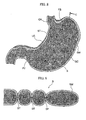
FIGS. 1 and2 , a suturing tool as an endoscopic treatment tool 1 according to the present invention is a suturing tool which is inserted into a stomach (hollow organ) via the mouth, nose, anus or other natural orifice, and performs a suturing treatment inside of the stomach or abdominal cavity. - The suturing tool 1 includes a hollow organ lining support 2 (herein after abbreviated as a stomach wall support) which is smaller than the smallest diameter of a passage from the natural orifice to the hollow organ, a portion of the hollow organ lining support being able to expand so as to have a diameter larger than the smallest diameter of a diameter of cardia of stomach, in other words, the passage from the natural orifice to the hollow organ; and an
inner tube 3 which connects to atubular body 2A which is described later, of thestomach wall support 2. - The
stomach wall support 2 includes thetubular body 2A includingfine threads 2a netted into a cylindrical shape and a lateral face thereof is covered with afilm 2b, and adistal end portion 2B consisted offine threads 2a netted to cover the distal end open portion of thetubular body 2A and is also covered with thefilm 2b. - A pair of
plates 5A provided with a window (open portion) 5A thereon are disposed on the lateral face of thetubular body 2A symmetrically with respect to the central axis C. The number ofwindow 5A is not limited thereto. One or a plurality of windows may be provided. - A proximal end of the
tubular body 2A is connected to theinner tube 3. Thetubular body 2A accommodates a suturing needle not illustrated. Thetubular body 2A also includes anaspiration lumen 6 connected to an aspirator (not illustrated). - The 2B is disposed to cover the distal opening of the
tubular body 2A, and an opening 6A of theaspiration lumen 6 is disposed on a center thereof. Upon compression of thetubular body 2A, thedistal end portion 2B is compressed such that the center is projected out to the distal end. Upon dilation of thetubular body 2A, thedistal end portion 2B is dilated so as to deform into a plane. - The
stomach wall support 2 is inserted into the overtube OT in which the outer diameter has a substantially same diameter as an inner diameter of the cardia CA, in a compressed state. The distal end of the overtube OT generates various curved movements with an operation of a curved knob N disposed at a proximal end of the overtube OT. - An outer diameter of the
inner tube 3 has a diameter substantially equal to an outer diameter of the compressed state of thetubular body 2A. Anoperation knob 7 which operates a suturing needle (a suturing tool) housed in thetubular body 2A is provided at the proximal end thereof. An insertion opening 3A of the endoscope E is provided at a distal end of theinner tube 3. An aspiration opening 3B which is connected to a distal end of theaspiration lumen 6 is disposed in the vicinity of the insertion opening 3A. - The actions of the present embodiment will now be described in line with a suturing procedure as shown by
FIG. 3 to 5 . - The suturing procedure according to the present embodiment consists of an insertion step (S01) of inserting the overtube OT containing the
stomach wall support 2, into the stomach S via the mouth of the patient; a distending step (S20) in which the diameter of thestomach wall support 2 is expanded within the stomach S; and a suturing step (S03) of suturing a stomach wall SW from the cardia CA to a pylorus PY into a tubular shape. - First, the insertion step (S01) is performed by inserting the overtube OT accommodating the
stomach wall support 2 and theinner tube 3 therein, into in the vicinity of the cardia CA of the stomach S via the mouth of the patient. At this time, thestomach wall support 2 is in a compressed status into an inner radial direction pressed by the overtube OT. - Next, the distending step is performed by shifting the overtube OT to a proximal side relative to the
inner tube 3 so as to expose thestomach wall support 2. From this movement, thestomach wall support 2 is released from the OT compressing the lateral face of thestomach wall support 2 into the radial direction, and the diameter of thestomach wall support 2 expands to its original outer diameter size which is larger than the diameter of the cardia CA as shown inFIG 3 . At this time, thedistal end portion 2B is also deformed into a flat plane after expansion of the diameter. - Then the suturing step (S03) is performed by aspirating the stomach S by the
aspiration lumen 6 accompanying the unshown aspirator, and the stomach S is contracted. Upon contraction of the stomach S, the stomach wall SW attaches onto thestomach wall support 2. By further reducing the internal pressure of thestomach wall support 2 compared to the pressure of the stomach S, a part of the stomach wall SW is pulled into thewindows 5A so as to aspirate the stomach wall SW, resulting the formation of a tubular section having a diameter larger than the inner diameter of the cardia CA within the stomach S by thestomach wall support 2. - The stomach wall SW pulled into the
windows 5A is later sutured by the suturing needle not illustrated. Suturing is performed by moving theinner tube 3 or by moving the overtube OT in conjunction with the movement of theinner tube 3 accompanying the overtube OT, so that stitches ST are lined up along a lesser curvature LC from the cardia CA to the pylorus PY of the stomach S as shown inFIG. 4 . - Alternatively, as shown in
FIGS. 6 and 7 , suturing from the cardia CA to the pylorus PY may be performed by; suturing in a straight line from the lesser curvature LC to the vicinity of a greater curvature GC of the stomach (but not suturing all the way to the GC); then suturing in a straight line from the greater curvature GC to the vicinity of the lesser curvature LC (but not suturing all the way to the lesser curvature LC) from the pylorus PY side at a predetermined distance away. This suturing method may be repeated in sequence a plurality of times so that stitches reach the vicinity of the pylorus PY. In this case, suturing may be performed so as to clinch a fundus of stomach FS as shown inFIGS. 6 and 7 , or without such clinching as shown inFIGS. 8 and 9 . - After suturing is completed, the
inner tube 3 is moved with respect to the overtube OT, so that thestomach wall support 2 is received by being compressed into the overtube OT. Once thestomach wall support 2 is completely received inside of the overtube OT, the entire suturing tool 1 and the overtube OT are drawn out from the mouth of the patient. - According to the suturing tool 1 and the suturing methods using the same, the tubular section in which the inner diameter is larger than the inner diameter of the cardia CA can be formed within the stomach S by virtue of a provision of the
stomach wall support 2 then sutured into the tubular section by expansion of thestomach wall support 2 within the stomach S. Because thewindows 5A are disposed on thestomach wall support 2, suturing with the unshown suturing needle can be performed via thewindows 5A. Furthermore, thestomach wall support 2 is provided with the overtube OT which freely advances and retracts with respect to thestomach wall support 2, thereby the size of thestomach wall support 2 can be adjusted according to a protrusion or recession amount of thestomach wall support 2 from the overtube OT. - Next, a second embodiment will be described in line with
FIGS. 10 to 13 . - The second embodiment differs from the first embodiment in that a
tubular body 11 of asuturing tool 10 in the present embodiment is a rigid body being able to pass through the cardia CA of the stomach S, and astomach wall support 12 is disposed as a part of a lateral face of thetubular body 11, so as to protrude and retract with respect to thetubular body 11. - An opening
portion 13 is provided on the lateral face of thetubular body 11 for thestomach wall support 12 being able to protrude and retract with respect to thetubular body 11. - A
suturing tool 10 includes atransfer mechanism 15 which makes thestomach wall support 12 protrude and retract with respect to the openingportion 13 in a radial direction (normal line direction to the opening portion 13). Thetransfer mechanism 15 is the rigid body and includes anoperation wire 15A in which the distal end is fixed to thetubular body 11. A proximal end of theoperation wire 15A extends to an operation section proximal to an operator. A proximal end of thetubular body 11 is connected to theinner tube 3. - The
stomach wall support 12 is surrounded by an outerlateral face 12a, an innerlateral face 12b, and a pair of aspiration faces 12c; the outerlateral face 12a which is a part of the lateral face of thetubular body 11, the innerlateral face 12b which comes into contact with an inner lateral face of thetubular body 11 which is symmetrical to the openingportion 13 and a pair of aspiration faces 12c in which a pair ofwindows 16 where stomach wall SW is aspirated into are provided on both aspiration faces 12c. - A pair of high-
frequency electrodes 17 is provided on an inner side of the outerlateral face 12a in order to cauterize the stomach wall SW aspirated from thewindows 16. - The high-
frequency electrodes 17 are connected to an operation section proximal to the operator not illustrated via theoperation wire 15A, the high-frequency electrodes 17 are moved to thetubular body 11 side by crossing through thewindow 16 upon pulling theoperation wire 15A by the operation of the operation section. - The inner
lateral face 12b is in arc-shape formed along the shape of the inner lateral face of thetubular body 11. Since the surface area of the arc-shape of the innerlateral face 12b is larger than the opened area of the openingportion 13, the innerlateral face 12b is detained inside of thetubular body 11. - The pair of
windows 16 are disposed so as to oppose each other, in a direction perpendicular to the central axis C. Anaxis 18A which is connected to an operation knob is provided in thestomach wall support 12 along the innerlateral face 12b and the outerlateral face 12a of thestomach wall support 12. Furthermore, a plurality of ringshaped suturing needles 18B are disposed with a predetermined distance apart from each other around theaxis 18A as the center of theneedles 18B. - The actions of the present embodiment will now be described in line with the
suturing tool 10 - The suturing procedure according to the present embodiment consists of an insertion step (S11) of inserting the overtube OT provided with the
stomach wall support 12 into the stomach S via the mouth of the patient; a distending step (S12) in which thestomach wall support 12 is projected out from thetubular body 11 within the stomach S; and a suturing step (S13) of suturing the stomach wall SW from the cardia CA to the pylorus PY into a tubular shape. - First, the insertion step (S11) of inserting the overtube OT provided with the
tubular body 11 and thestomach wall support 12 in a state in which thestomach wall support 12 is housed inside of thetubular body 11, into the vicinity of the cardia CA of the stomach S via the mouth of the patient is performed. - Next, the distending step (S 12) is performed by pulling the
operation wire 15A with an operation of thetransfer mechanism 15. At this time, thestomach wall support 12 moves until the innerlateral face 12b comes into a contact with thewindow 16 of thetubular body 11 so as to expose thewindow 16 of thestomach wall support 12 from the inside of thetubular body 11 to the outside thereof. - Then the suturing step (S13) is performed by aspirating the stomach S by the aspirator not illustrated, and the stomach S is contracted. Upon contraction of the stomach S, the stomach wall SW attaches to the
stomach wall support 12. - By reducing the internal pressure of the
stomach wall support 12 compared to a pressure of the stomach S, a part of the stomach wall SW is pulled into thewindows 16 so as to aspirate the stomach wall SW, resulting a formation of a tubular section having a diameter larger than the inner diameter of the cardia CA within the stomach S by thestomach wall support 12. - Here, by pulling the
operation wire 15A at the operation section with a high-frequency power being supplied from a high-frequency power source (not illustrated), the high-frequency electrodes 17 moves to thetubular body 11 side by crossing through thewindow 16 by incising or cauterizing a mucous of the stomach wall SW, thereby promoting coalescence after the suturing treatment. - The stomach wall SW is then sutured by suturing
needles 18B with a rotation of theaxis 18A by an operation on an operation knob. - Upon completion of suturing, the
transfer mechanism 15 is operated again and thestomach wall support 12 is pulled into thetubular body 11 by pulling theoperation wire 15A so that the outerlateral face 12a is returned to the same plane as the lateral face of thetubular body 11. Then theentire suturing tool 10 is drawn out from the mouth of the patient. - According to the
suturing tool 10 and the suturing methods using the same, the same effect and action can be obtained as described in the first embodiment. - Next, a third embodiment will be described in line with
FIGS. 14 to 17 . - The third embodiment differs from the second embodiment in that a
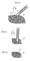
stomach wall support 21 of asuturing tool 20 according to the present embodiment is pivotally mounted on apivot support pin 25 as a part of a lateral face of atubular body 22 so as to be detachably mounted to awindow 23 formed on atubular body 22. - Both of the
axis 18A and the suturing needles 18B are housed inside of thetubular body 22 in a position where the suturing needles 18B can pierce the stomach wall SW aspirated from awindow 23.
Thewindow 23 is formed in a substantially rectangular shape in plan view along the central axis C as the longitudinal direction. - The
stomach wall support 21 is also formed in a substantially rectangular shape in plan view along the central axis C as the longitudinal direction so as to cover thewindow 23. Adistal end 21a of thestomach wall support 21 is pivotally mounted about thepivot support pin 25 which elongates to a direction crossing with the central axis C so as to freely rotate about thepivot support pin 25. - The
stomach wall support 21 is formed in the same curved-shape as the lateral face of thetubular body 22 and is provided with an outerlateral face 21b on the outer peripheral side and an innerlateral face 21c on the inner peripheral side of thestomach wall support 21. Thestomach wall support 21 is rotated by a transfer mechanism not illustrated. - Next, the action of the
suturing tool 20 according to the present embodiment is described along with the suturing method. - The suturing procedure according to the present embodiment includes an insertion step (S21) of inserting the overtube OT provided with the
stomach wall support 21 into the stomach S via the mouth of the patient; a distending step (S22) in which thetubular body 22 is projected out within the stomach S; and a suturing step (S23) of suturing a stomach wall SW from the cardia CA to the pylorus PY of the stomach S into a tubular shape. - First, the insertion step (S21) of inserting the
stomach wall support 21 in a state in which thestomach wall support 21 is closed so as to cover thewindow 23 of thetubular body 22, into the vicinity of the cardia CA of the stomach S via the mouth of the patient is performed. - Next, the distending step (S22) is performed by pivoting the
stomach wall support 21 about thepivot support pin 25, so that aproximal end 21d of thestomach wall support 21 moves away from thetubular body 22, and thewindow 23 of thestomach wall support 21 is exposed. - Then the suturing step (S23) is performed by aspirating the stomach S by the aspirator (not illustrated), and the stomach S is contracted. Upon contraction of the stomach S, the stomach wall SW attaches to both sides of the stomach wall support 21 (i.e., the outer
lateral face 21b and the innerlateral face 21c as shown inFIG. 16 ), resulting in the formation of a tubular section having a diameter larger than the inner diameter of the cardia CA within the stomach S by thetubular body 22. - Then a portion of the stomach wall SW surrounded by the
window 23 is sutured with the suturing needles 18B by rotating theaxis 18A. - According to the
suturing tool 20 and a suturing method using the same, the same action and effect as those of the second embodiment can be obtained. - The
tubular body 22 may be disposed on any position along the overtube OT' as shown inFIG 17 , and is not limited to being disposed on the distal end of thetubular body 22. Thewindow 23 of a tubular body 26 is disposed in the vicinity of the cardia CA, and the distal end of the tubular body 26 is disposed in the duodenum DU by passing through the pylorus PY. - At this time, it is preferable to provide a balloon 27 which expands its diameter so as to close the duodenum DU.
- By providing the balloon, the duodenum DU can be closed by inflating the balloon and the position of the
tubular body 22 can be determined with respect to the stomach S thereby a precise suturing treatment can be ensured. - Next, a forth embodiment will be described in line with
FIGS. 18 to 20 . - The forth embodiment differs from the third embodiment in that a
stomach wall support 31 of asuturing tool 30 according to the present embodiment is pivotally mounted on a lateral face of atubular body 32 about apivot support pin 35 so as to engage with awindow 33 formed on thetubular body 32, and is provided as a part of the lateral face of thetubular body 32. - The
stomach wall support 31 is part of the tubular body formed along a periphery thereof, and is divided at the center along the periphery of thestomach wall support 31 hence thestomach wall support 31 is provided as a pair. Anopposed end 31a of each pair of thestomach wall support 31 is pivotally mounted so as to freely rotate about thepivot support pin 35 on the lateral face of thetubular body 32. - The
stomach wall support 31 is formed in the same curved-shape as the lateral face of thetubular body 32. Thestomach wall support 31 is rotated by a transfer mechanism (not illustrated). - The
window 33 provided on the lateral face of thetubular body 32 is formed in a strip-shape so that the pair of the stomach wall supports 31 engage each other. The suture needles 18B are provided in the vicinity of thewindow 33. - The suture needles 18B are formed of a super-elastic wire and curved in advance, and is housed in a tubular shaped
receiver 36 included in atubular body 32 by being stretched into a straight shape at the time of operation. - Next, action of a
suturing tool 30 according to the present embodiment is described along with the suturing method. - Similar to the third embodiment, the suturing procedure according to the present embodiment consists of an insertion step (S21) of inserting the overtube OT provided with the
stomach wall support 31 into the stomach S via the mouth of the patient; a distending step (S22) in which thestomach wall support 31 is projected out within the stomach S; and a suturing step (S23) of suturing the stomach wall SW into a tubular shape from the cardia CA to the pylorus PY. - First, the insertion step (S21) of inserting the overtube OT provided with the
stomach wall support 31 into the mouth of the patient is performed. - Next, the distending step (S22) is performed by pivoting the pair of the stomach wall supports 31 about the
pivot support pin 35 with an operation of a transfer mechanism, so that another end of the pair of stomach wall supports 31 move away from thetubular body 32. With this movement, thewindow 33 formed on thestomach wall support 31 also moves away from thetubular body 32. - In the suturing step (S23), the stomach S is aspirated by the
aspiration lumen 6 operated by an aspirator (not illustrated), and the stomach S is contracted. - Upon contraction of the stomach S, the stomach wall SW attaches onto an inner side of the
stomach wall support 31 as shown inFIG 20 , resulting a formation of a tubular section having its diameter larger than the inner diameter of the cardia CA, within the stomach S by thestomach wall support 31. - Then a portion of the stomach wall SW surrounded by the
window 33 is sutured with the suturing needles 18B by rotating theaxis 18A. - According to the
suturing tool 30 and a suturing method using the same, the same action and effect of those in the third embodiment can be obtained. - Next, a fifth embodiment will be described in line with
FIGS. 21 to 27 . - The fifth embodiment differs from the first embodiment in that a high-
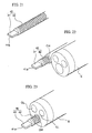
frequency treatment tool 40 in the present embodiment is used in the suturing procedure within the stomach S or within the abdominal cavities with the suturing tools described in the above embodiments as shown inFIG. 21 , and is provided with a high-frequency electrode 41 inserted into an instrument channel of an endoscope E in a manner of freely protrudes and retracts. - The high-
frequency electrode 41 is connected to a high-frequency power source not illustrated via a flexible elongated shaft of aconductive portion 42. Adistal end face 41a of the high-frequency electrode 41 is formed in a substantially rectangular shape in plan view in which its longitudinal direction thereof has a substantially same length of an internal diameter of an insertion channel CH of the treatment tool. - The insertion channel of the treatment tool CH is disposed on an outer periphery of the endoscope E as shown in
FIG. 22 . Alternatively, the high-frequency treatment tool 40 may also be inserted into a pre-formed insertion channel CH' of the endoscope E, as shown inFIG. 23 . - Next, the action of the high-
frequency treatment tool 40 according to the present embodiment is described along with the suturing method. - The high-
frequency treatment tool 40 according to the present embodiment is used for cauterizing sutured tissues after completion of the insertion step (S01), the distending step (S02) and the suturing step (S03) in the first embodiment - After completion of the treatment described in the first embodiment, the high-
frequency electrode 41 inserted into the insertion channel CH is made to protrude from the distal end thereof. - As shown in
FIG 24 , a longitudinal direction of a substantially rectangular shape in plan view of thedistal end face 41a of the high-frequency electrode 41 is set to align between stitches ST, and thedistal end face 41a abuts a tissue as shown inFIG 25 . Then a cauterized section B is formed by cauterizing the section of tissue abutted with the high-frequency electrode 41 as shown inFIG. 26 , by a high-frequency current of predetermined condition being supplied from a high-frequency power source. - According to the high-
frequency treatment tool 40, sutured tissue can be cauterized, thereby promoting coalescence of the tissues after the suturing treatment. - Alternatively, as shown in
FIG. 27 , a high-frequency treatment tool 43 may be provided with acap 45 detachably disposed at a distal end of the endoscope E, and the high-frequency electrode 41 may be disposed in a protruded manner from the distal end face of thecap 45 so that anopening portion 45b may be disposed on adistal end face 45a adjacent to the high-frequency electrode 41. - In this case, even if the
cap 45 is disposed at the distal end of the endoscope E, theopening portion 45b still opens having a sufficient size to expose an object lens OL and a lamination lens LL via theopening portion 45b. A distal end of aconductive wire 46 for supplying electricity to the high-frequency electrode 41 disposed along the endoscope E is connected to thecap 45. - According to the high-
frequency treatment tool 43, by disposing thecap 45 at the distal end of the endoscope E, the high-frequency electrode 41 can be advanced into a sutured portion along with the endoscope E, thereby the tissue can be cauterized. - A sixth embodiment differs from the fifth embodiment in that a provision of a
balloon 51 which inflates by fluid being introducing thereinto and a high-frequency electrode 52 disposed on an outer peripheral surface of aninflatable balloon 51 in a high-frequency treatment tool 50 according to the present embodiment, as shown inFIGS. 28 and29 . - A
cap 53 forms in a cylindrical-shape and adistal end portion 56 including anopening 55A of anaspiration lumen 55 in the center thereof is disposed on a distal end of thecap 53. - The
balloon 51 is disposed on a lateral surface of thecap 53 and inflates by fluid being flowed thereinto via a connecting tube (not illustrated). A high-frequency electrode 52 is disposed on an outer surface of theballoon 51 in a way that the longitudinal direction of adistal end face 52a aligns with the central axis C of thecap 53. - Next, action of the high-
frequency treatment tool 50 according to the present embodiment is described along with the suturing method. - The high-
frequency treatment tool 50 according to the present embodiment is used for cauterizing sutured tissues in an insertion step (S33) and a distending step (S32) instead of the insertion step (S01) and the distending step (S02) as a pre-treatment of the suturing step (S03) in the first embodiment. - In the insertion step (S31), the
cap 53 is fitted on the distal end of the overtube OT instead of an endoscope, and a high-frequency treatment tool 50 along with the overtube OT is inserted into the vicinity of the cardia CA of the stomach S via the mouth of the patient. At this time, theballoon 51 is deflated. - In the distending step (S32), a fluid is introduced into the
balloon 51 via the connecting tube. By introducing fluid into theballoon 51, theballoon 51 is inflated so that the high-frequency electrode 52 moves away from thecap 53; in other words, moving toward the outer diameter. - In this state, the stomach S is aspirated by an
aspiration lumen 55 with an operation of an aspirator (not illustrated), and the stomach S is contracted. Upon contraction of the stomach S, the stomach wall SW attaches to the outer peripheral surface of theballoon 51 and to the high-frequency electrode 52. Then, a high-frequency electricity is supplied to the high-frequency electrode 52. - At this time, as shown in
FIG 30 , a cauterized section B is formed by a tissue which is in contact to the high-frequency electrode 52. - At this state, the
cap 53 is advanced from a position in the vicinity of the cardia CA to the pylorus PY of the stomach S by advancing the overtube OT. Thus, a tubular section in which the diameter is larger than the inner diameter of the cardia CA is formed within the stomach S. - The high-
frequency treatment tool 50 is then drawn out and an endoscope provided with a suturing tool (not illustrated) is inserted into the overtube OT instead, and the suturing step (S03) is performed by the suturing tool. - According to the high-
frequency treatment tool 50, a tubular section in which the diameter is larger than the inner diameter of the cardia CA can be formed prior to the suturing step. Since the tissue is cauterized at this time, the tissue can be coalesced hence the suturing procedure can be performed in a stable manner. - Alternatively, as shown in
FIG 31 , acap 58 of a high-frequency treatment tool 57 may be disposed on theovertube 58 along the central axis C so as to freely advance and retract. In such a case, it is not necessary to move the entire overtube OT to the pylorus side PY, only thecap 58 may be moved with respect to the overtube OT. - While preferred embodiments of the invention have been described and illustrated above, it should be understood that these are exemplary of the invention and are not to be considered as limiting. Additions, omissions, substitutions, and other modifications can be made without departing from the scope of the invention. Accordingly, the invention is not to be considered as being limited by the foregoing description, and is only limited by the scope of the appended claims.
- For example, although the suturing tool is disposed at the distal end of the endoscope E in the above embodiment, the present invention is not limited thereto; for example, it may be disposed at the distal end of the overtube OT.
Claims (14)
- An endoscopic treatment tool which is inserted into a hollow organ through a natural orifice and performs a suturing treatment within the hollow organ or abdominal cavity, comprising:a hollow organ lining support, a portion of the hollow organ lining support being able to expand so as to have a diameter larger than the smallest diameter of a passage from the natural orifice to the hollow organ.
- The endoscopic treatment tool according to claim 1, wherein:an opening portion is provided on the hollow organ lining support.
- The endoscopic treatment tool according to Claim 1, further comprising:a tubular body in which the diameter is smaller than the smallest diameter of the passage from the natural orifice to the hollow organ; andthe hollow organ lining support is provided as a part of a lateral face of the tubular body so as to freely protrude and retract with respect to the tubular body.
- The endoscopic treatment tool according to Claim 3, wherein:an opening portion is provided on the hollow organ lining support; anda transfer mechanism is provided on the tubular body so as to protrude and retract the hollow organ lining support in a normal direction of the lateral face of the opening portion.
- The endoscopic treatment tool according to Claim 3, wherein:an opening portion is provided on the tubular body; andthe hollow organ lining support is pivotally mounted on the opening portion in a detachable manner, forming a part of the lateral face of the tubular body.
- The endoscopic treatment tool according to Claim 3, wherein:an opening portion is provided on the tubular body; andthe hollow organ lining support is pivotally mounted on the lateral face of a tubular body so as to be able to engage with the opening portion, forming a part of the lateral face of the tubular body.
- The endoscopic treatment tool according to Claim 1, wherein:a high-frequency electrode is provided on the hollow organ lining support.
- A high-frequency treatment tool which is inserted into a hollow organ via a natural orifice and used in a suturing treatment performed within the hollow organ or abdominal cavity, comprising:a high-frequency electrode which is inserted into a treatment channel provided on an endoscope so as to freely protrude and retract, and a high-frequency current is applied onto the high-frequency electrode.
- A high-frequency treatment tool which is inserted into a hollow organ via a natural orifice and used in a suturing treatment performed within the hollow organ or abdominal cavity, comprising:a cap detachably disposed on a distal end of an endoscope; anda high-frequency electrode applied a high-frequency current is disposed on the cap.
- A high-frequency tool according to claim 9, wherein:the high-frequency electrode is disposed on a distal end face of the cap in a protruded manner; andan opening portion is provided on the distal end face adjacent to the high-frequency electrode.
- A high-frequency tool according to claim 9, wherein:an inflatable balloon is provided on a lateral face of the cap and expand its diameter by fluid being introduced into the balloon; andthe high-frequency electrode is provided on an outer periphery of the balloon.
- A suturing procedure of suturing an lining of a hollow organ by an endoscopic treatment tool which is inserted into the hollow organ via a natural orifice, comprising the following steps:inserting a hollow organ lining support provided on the endoscopic treatment tool into the hollow organ, at least a portion of the hollow organ lining support being able to expand its diameter larger than the smallest diameter of a passage from the natural orifice to the hollow organ;distending at least a portion of the hollow organ lining support within the hollow organ; andsuturing the lining of the hollow organ into a tubular shape.
- The suturing procedure according to claim 12, wherein:the suturing step is performed along a lesser curvature, from the cardia to the pylorus of the stomach.
- The suturing procedure according to claim 12, wherein:the suturing step is performed in a straight line from one of the lesser curvature or a greater curvature to the vicinity of the other, from the cardia to the pylorus of the stomach.
Applications Claiming Priority (1)
| Application Number | Priority Date | Filing Date | Title |
|---|---|---|---|
| US87770106P | 2006-12-28 | 2006-12-28 |
Publications (3)
| Publication Number | Publication Date |
|---|---|
| EP1938758A2 true EP1938758A2 (en) | 2008-07-02 |
| EP1938758A3 EP1938758A3 (en) | 2008-07-30 |
| EP1938758B1 EP1938758B1 (en) | 2018-08-29 |
Family
ID=39156348
Family Applications (1)
| Application Number | Title | Priority Date | Filing Date |
|---|---|---|---|
| EP07025056.8A Active EP1938758B1 (en) | 2006-12-28 | 2007-12-21 | Endoscopic treatment tool |
Country Status (4)
| Country | Link |
|---|---|
| US (1) | US8647353B2 (en) |
| EP (1) | EP1938758B1 (en) |
| JP (1) | JP5350627B2 (en) |
| CN (1) | CN101292885B (en) |
Cited By (2)
| Publication number | Priority date | Publication date | Assignee | Title |
|---|---|---|---|---|
| WO2009134983A1 (en) * | 2008-05-01 | 2009-11-05 | Ethicon Endo-Surgery, Inc. | Balloon tissue damage device |
| WO2009134999A1 (en) | 2008-05-01 | 2009-11-05 | Ethicon Endo-Surgery, Inc. | Method and apparatus for marking a lumenal wall |
Families Citing this family (3)
| Publication number | Priority date | Publication date | Assignee | Title |
|---|---|---|---|---|
| KR102292017B1 (en) * | 2011-02-16 | 2021-08-20 | 더 제너럴 하스피탈 코포레이션 | Optical coupler for an endoscope |
| CN103919580B (en) * | 2014-04-23 | 2016-01-20 | 王恺京 | Stomach sleeve resection inserting tube |
| KR20240036901A (en) * | 2022-09-14 | 2024-03-21 | 주식회사 엔도로보틱스 | Auxiliary cap for endoscope |
Citations (5)
| Publication number | Priority date | Publication date | Assignee | Title |
|---|---|---|---|---|
| US20030127491A1 (en) | 1998-06-19 | 2003-07-10 | Adams Ronald D. | Integrated surgical staple retainer for a full thickness resectioning device |
| WO2004050971A2 (en) | 2002-11-29 | 2004-06-17 | Liddicoat John R | Apparatus and method for manipulating tissue |
| WO2006023764A2 (en) | 2004-08-18 | 2006-03-02 | Endogastric Solutions, Inc. | Transoral endoscopic gastroesophageal flap valve restoration device, assembly, system and method |
| WO2006112849A1 (en) | 2005-04-15 | 2006-10-26 | Satiety, Inc. | Single fold device for tissue fixation |
| US20060253127A1 (en) | 2005-05-04 | 2006-11-09 | Bernard Medical, Llc | Endoluminal linear suturing device |
Family Cites Families (36)
| Publication number | Priority date | Publication date | Assignee | Title |
|---|---|---|---|---|
| GB2260704B (en) * | 1991-09-30 | 1995-08-23 | Philip Richardson | Suturing apparatus |
| CA2106127A1 (en) * | 1992-09-23 | 1994-03-24 | Peter W.J. Hinchliffe | Instrument for closing trocar puncture wounds |
| US5374275A (en) * | 1993-03-25 | 1994-12-20 | Synvasive Technology, Inc. | Surgical suturing device and method of use |
| US5503634A (en) * | 1993-04-28 | 1996-04-02 | Christy; William J. | Surgical stab wound closure device and method |
| US5613975A (en) * | 1993-04-28 | 1997-03-25 | Christy; William J. | Endoscopic suturing device and method |
| US5507755A (en) * | 1993-08-03 | 1996-04-16 | Origin Medsystems, Inc. | Apparatus and method for closing puncture wounds |
| US5397325A (en) * | 1993-11-09 | 1995-03-14 | Badiaco, Inc. | Laparoscopic suturing device |
| US5562686A (en) * | 1995-04-19 | 1996-10-08 | United States Surgical Corporation | Apparaus and method for suturing body tissue |
| US5846253A (en) * | 1995-07-14 | 1998-12-08 | C. R. Bard, Inc. | Wound closure apparatus and method |
| US6117144A (en) * | 1995-08-24 | 2000-09-12 | Sutura, Inc. | Suturing device and method for sealing an opening in a blood vessel or other biological structure |
| US5707379A (en) * | 1995-10-20 | 1998-01-13 | Coral Medical | Method and apparatus for intracorporeal suturing |
| US6074401A (en) * | 1997-01-09 | 2000-06-13 | Coalescent Surgical, Inc. | Pinned retainer surgical fasteners, instruments and methods for minimally invasive vascular and endoscopic surgery |
| US5868762A (en) * | 1997-09-25 | 1999-02-09 | Sub-Q, Inc. | Percutaneous hemostatic suturing device and method |
| US6478210B2 (en) * | 2000-10-25 | 2002-11-12 | Scimed Life Systems, Inc. | Method and device for full thickness resectioning of an organ |
| US7842048B2 (en) * | 2006-08-18 | 2010-11-30 | Abbott Laboratories | Articulating suture device and method |
| US7001400B1 (en) * | 1999-03-04 | 2006-02-21 | Abbott Laboratories | Articulating suturing device and method |
| US6767352B2 (en) * | 1999-08-03 | 2004-07-27 | Onux Medical, Inc. | Surgical suturing instrument and method of use |
| US6231561B1 (en) * | 1999-09-20 | 2001-05-15 | Appriva Medical, Inc. | Method and apparatus for closing a body lumen |
| US6533795B1 (en) * | 2000-04-11 | 2003-03-18 | Opus Medical, Inc | Dual function suturing apparatus and method |
| US7083629B2 (en) * | 2001-05-30 | 2006-08-01 | Satiety, Inc. | Overtube apparatus for insertion into a body |
| US6558400B2 (en) * | 2001-05-30 | 2003-05-06 | Satiety, Inc. | Obesity treatment tools and methods |
| JP4489428B2 (en) * | 2001-10-01 | 2010-06-23 | サージカル ソリューションズ リミテッド ライアビリティ カンパニー | Suture device |
| CA2467918A1 (en) | 2001-12-20 | 2003-07-03 | Rex Medical, L.P. | Apparatus and method for treating gastroesophageal reflux disease |
| US6790214B2 (en) * | 2002-05-17 | 2004-09-14 | Esophyx, Inc. | Transoral endoscopic gastroesophageal flap valve restoration device, assembly, system and method |
| US6773440B2 (en) | 2002-07-02 | 2004-08-10 | Satiety, Inc. | Method and device for use in tissue approximation and fixation |
| US7083630B2 (en) * | 2002-08-29 | 2006-08-01 | Scimed Life Systems, Inc. | Devices and methods for fastening tissue layers |
| WO2004021894A1 (en) * | 2002-09-09 | 2004-03-18 | Brian Kelleher | Device and method for endoluminal therapy |
| US7160309B2 (en) * | 2002-12-31 | 2007-01-09 | Laveille Kao Voss | Systems for anchoring a medical device in a body lumen |
| US7462188B2 (en) * | 2003-09-26 | 2008-12-09 | Abbott Laboratories | Device and method for suturing intracardiac defects |
| US20050075654A1 (en) * | 2003-10-06 | 2005-04-07 | Brian Kelleher | Methods and devices for soft tissue securement |
| US8252009B2 (en) * | 2004-03-09 | 2012-08-28 | Ethicon Endo-Surgery, Inc. | Devices and methods for placement of partitions within a hollow body organ |
| US7500980B2 (en) * | 2004-05-07 | 2009-03-10 | Ethicon Endo-Surgery, Inc. | Method and instrument for effecting anastomosis of respective tissues defining two body lumens |
| AU2005262460B2 (en) * | 2004-06-16 | 2011-12-15 | Smith & Nephew, Inc. | Suture passing |
| WO2007025302A2 (en) * | 2005-08-26 | 2007-03-01 | G-Surge Medical Solutions, Inc. | Suturing apparatus and methods |
| US7850712B2 (en) * | 2005-11-15 | 2010-12-14 | Ethicon Endo-Surgery, Inc. | Self-shielding suture anchor |
| WO2007078003A1 (en) * | 2006-01-06 | 2007-07-12 | Olympus Medical Systems Corp. | Trans-natural opening based or transcutaneous medical system |
-
2007
- 2007-12-21 EP EP07025056.8A patent/EP1938758B1/en active Active
- 2007-12-26 JP JP2007334560A patent/JP5350627B2/en active Active
- 2007-12-26 CN CN2007101606381A patent/CN101292885B/en active Active
- 2007-12-27 US US11/965,299 patent/US8647353B2/en active Active
Patent Citations (5)
| Publication number | Priority date | Publication date | Assignee | Title |
|---|---|---|---|---|
| US20030127491A1 (en) | 1998-06-19 | 2003-07-10 | Adams Ronald D. | Integrated surgical staple retainer for a full thickness resectioning device |
| WO2004050971A2 (en) | 2002-11-29 | 2004-06-17 | Liddicoat John R | Apparatus and method for manipulating tissue |
| WO2006023764A2 (en) | 2004-08-18 | 2006-03-02 | Endogastric Solutions, Inc. | Transoral endoscopic gastroesophageal flap valve restoration device, assembly, system and method |
| WO2006112849A1 (en) | 2005-04-15 | 2006-10-26 | Satiety, Inc. | Single fold device for tissue fixation |
| US20060253127A1 (en) | 2005-05-04 | 2006-11-09 | Bernard Medical, Llc | Endoluminal linear suturing device |
Cited By (4)
| Publication number | Priority date | Publication date | Assignee | Title |
|---|---|---|---|---|
| WO2009134983A1 (en) * | 2008-05-01 | 2009-11-05 | Ethicon Endo-Surgery, Inc. | Balloon tissue damage device |
| WO2009134999A1 (en) | 2008-05-01 | 2009-11-05 | Ethicon Endo-Surgery, Inc. | Method and apparatus for marking a lumenal wall |
| US8133217B2 (en) | 2008-05-01 | 2012-03-13 | Ethicon Endo-Surgery, Inc. | Method and apparatus for marking a lumenal wall |
| US8357156B2 (en) | 2008-05-01 | 2013-01-22 | Ethicon Endo-Surgery, Inc. | Balloon tissue damage device |
Also Published As
| Publication number | Publication date |
|---|---|
| CN101292885A (en) | 2008-10-29 |
| JP5350627B2 (en) | 2013-11-27 |
| CN101292885B (en) | 2011-06-22 |
| US20080242933A1 (en) | 2008-10-02 |
| EP1938758B1 (en) | 2018-08-29 |
| US8647353B2 (en) | 2014-02-11 |
| EP1938758A3 (en) | 2008-07-30 |
| JP2008161683A (en) | 2008-07-17 |
Similar Documents
| Publication | Publication Date | Title |
|---|---|---|
| US9289236B2 (en) | Mucosa separation apparatus, and method for mucosa separation | |
| US9827038B2 (en) | Medical instrument for endoscope and treatment method | |
| US10595873B2 (en) | Surgical staplers and related methods | |
| JP2677947B2 (en) | Device and method for forming an anatomical cavity for laparoscopic hernia treatment and patch used therefor | |
| EP1520531B1 (en) | Anastomosis applier | |
| KR101653180B1 (en) | Paranasal ostium finder devices and methods | |
| JP7048861B2 (en) | Intraluminal minimally invasive treatment system | |
| US20030225312A1 (en) | Endoscopic system for treating inside of body cavity | |
| US20100069710A1 (en) | treatment method | |
| JPH10511589A (en) | Expandable multifunctional device and method for creating a space at an occlusion site under an endoscope | |
| JP2006501039A (en) | Apparatus and method for treating urinary incontinence in women | |
| JP5124287B2 (en) | Medical indwelling member | |
| US8647353B2 (en) | Endoscopic treatment tool and suturing method using the same | |
| WO2005094663A1 (en) | Auxiliary tool for inserting medical instrument into living body | |
| JP3539124B2 (en) | Trocar with angle mechanism | |
| JP3560931B2 (en) | Endoscope insertion aid | |
| WO2016171132A1 (en) | Tissue pressing tool | |
| CN114588497B (en) | Device for treating intestinal anastomosis postoperative stenosis | |
| US20240108868A1 (en) | Implant | |
| JP4870936B2 (en) | Medical device insertion aid | |
| CN111743619A (en) | Expansion incision device | |
| KR20070018901A (en) | Auxiliary tool for inserting medical instrument into living body |
Legal Events
| Date | Code | Title | Description |
|---|---|---|---|
| PUAI | Public reference made under article 153(3) epc to a published international application that has entered the european phase |
Free format text: ORIGINAL CODE: 0009012 |
|
| PUAL | Search report despatched |
Free format text: ORIGINAL CODE: 0009013 |
|
| AK | Designated contracting states |
Kind code of ref document: A2 Designated state(s): AT BE BG CH CY CZ DE DK EE ES FI FR GB GR HU IE IS IT LI LT LU LV MC MT NL PL PT RO SE SI SK TR |
|
| AX | Request for extension of the european patent |
Extension state: AL BA HR MK RS |
|
| AK | Designated contracting states |
Kind code of ref document: A3 Designated state(s): AT BE BG CH CY CZ DE DK EE ES FI FR GB GR HU IE IS IT LI LT LU LV MC MT NL PL PT RO SE SI SK TR |
|
| AX | Request for extension of the european patent |
Extension state: AL BA HR MK RS |
|
| 17P | Request for examination filed |
Effective date: 20081216 |
|
| AKX | Designation fees paid |
Designated state(s): DE FR GB IE |
|
| 17Q | First examination report despatched |
Effective date: 20090408 |
|
| RAP1 | Party data changed (applicant data changed or rights of an application transferred) |
Owner name: OLYMPUS MEDICAL SYSTEMS CORP. Owner name: TERUMO KABUSHIKI KAISHA |
|
| RAP1 | Party data changed (applicant data changed or rights of an application transferred) |
Owner name: TERUMO KABUSHIKI KAISHA Owner name: OLYMPUS CORPORATION |
|
| RAP1 | Party data changed (applicant data changed or rights of an application transferred) |
Owner name: OLYMPUS CORPORATION Owner name: TERUMO KABUSHIKI KAISHA |
|
| GRAP | Despatch of communication of intention to grant a patent |
Free format text: ORIGINAL CODE: EPIDOSNIGR1 |
|
| INTG | Intention to grant announced |
Effective date: 20180316 |
|
| GRAS | Grant fee paid |
Free format text: ORIGINAL CODE: EPIDOSNIGR3 |
|
| GRAA | (expected) grant |
Free format text: ORIGINAL CODE: 0009210 |
|
| AK | Designated contracting states |
Kind code of ref document: B1 Designated state(s): DE FR GB IE |
|
| REG | Reference to a national code |
Ref country code: GB Ref legal event code: FG4D |
|
| REG | Reference to a national code |
Ref country code: IE Ref legal event code: FG4D |
|
| REG | Reference to a national code |
Ref country code: DE Ref legal event code: R096 Ref document number: 602007055920 Country of ref document: DE |
|
| REG | Reference to a national code |
Ref country code: DE Ref legal event code: R097 Ref document number: 602007055920 Country of ref document: DE |
|
| PLBE | No opposition filed within time limit |
Free format text: ORIGINAL CODE: 0009261 |
|
| STAA | Information on the status of an ep patent application or granted ep patent |
Free format text: STATUS: NO OPPOSITION FILED WITHIN TIME LIMIT |
|
| 26N | No opposition filed |
Effective date: 20190531 |
|
| GBPC | Gb: european patent ceased through non-payment of renewal fee |
Effective date: 20181221 |
|
| REG | Reference to a national code |
Ref country code: IE Ref legal event code: MM4A |
|
| PG25 | Lapsed in a contracting state [announced via postgrant information from national office to epo] |
Ref country code: IE Free format text: LAPSE BECAUSE OF NON-PAYMENT OF DUE FEES Effective date: 20181221 Ref country code: FR Free format text: LAPSE BECAUSE OF NON-PAYMENT OF DUE FEES Effective date: 20181231 |
|
| PG25 | Lapsed in a contracting state [announced via postgrant information from national office to epo] |
Ref country code: GB Free format text: LAPSE BECAUSE OF NON-PAYMENT OF DUE FEES Effective date: 20181221 |
|
| PGFP | Annual fee paid to national office [announced via postgrant information from national office to epo] |
Ref country code: DE Payment date: 20221125 Year of fee payment: 16 |
|
| P01 | Opt-out of the competence of the unified patent court (upc) registered |
Effective date: 20230620 |