EP1947642A1 - Active noise control system - Google Patents
Active noise control system Download PDFInfo
- Publication number
- EP1947642A1 EP1947642A1 EP07000818A EP07000818A EP1947642A1 EP 1947642 A1 EP1947642 A1 EP 1947642A1 EP 07000818 A EP07000818 A EP 07000818A EP 07000818 A EP07000818 A EP 07000818A EP 1947642 A1 EP1947642 A1 EP 1947642A1
- Authority
- EP
- European Patent Office
- Prior art keywords
- signal
- masking
- transfer function
- noise
- filter
- Prior art date
- Legal status (The legal status is an assumption and is not a legal conclusion. Google has not performed a legal analysis and makes no representation as to the accuracy of the status listed.)
- Granted
Links
Images


Classifications
-
- G—PHYSICS
- G10—MUSICAL INSTRUMENTS; ACOUSTICS
- G10L—SPEECH ANALYSIS OR SYNTHESIS; SPEECH RECOGNITION; SPEECH OR VOICE PROCESSING; SPEECH OR AUDIO CODING OR DECODING
- G10L21/00—Processing of the speech or voice signal to produce another audible or non-audible signal, e.g. visual or tactile, in order to modify its quality or its intelligibility
- G10L21/02—Speech enhancement, e.g. noise reduction or echo cancellation
- G10L21/0208—Noise filtering
-
- G—PHYSICS
- G10—MUSICAL INSTRUMENTS; ACOUSTICS
- G10K—SOUND-PRODUCING DEVICES; METHODS OR DEVICES FOR PROTECTING AGAINST, OR FOR DAMPING, NOISE OR OTHER ACOUSTIC WAVES IN GENERAL; ACOUSTICS NOT OTHERWISE PROVIDED FOR
- G10K11/00—Methods or devices for transmitting, conducting or directing sound in general; Methods or devices for protecting against, or for damping, noise or other acoustic waves in general
- G10K11/16—Methods or devices for protecting against, or for damping, noise or other acoustic waves in general
- G10K11/175—Methods or devices for protecting against, or for damping, noise or other acoustic waves in general using interference effects; Masking sound
- G10K11/178—Methods or devices for protecting against, or for damping, noise or other acoustic waves in general using interference effects; Masking sound by electro-acoustically regenerating the original acoustic waves in anti-phase
- G10K11/1781—Methods or devices for protecting against, or for damping, noise or other acoustic waves in general using interference effects; Masking sound by electro-acoustically regenerating the original acoustic waves in anti-phase characterised by the analysis of input or output signals, e.g. frequency range, modes, transfer functions
- G10K11/17813—Methods or devices for protecting against, or for damping, noise or other acoustic waves in general using interference effects; Masking sound by electro-acoustically regenerating the original acoustic waves in anti-phase characterised by the analysis of input or output signals, e.g. frequency range, modes, transfer functions characterised by the analysis of the acoustic paths, e.g. estimating, calibrating or testing of transfer functions or cross-terms
- G10K11/17815—Methods or devices for protecting against, or for damping, noise or other acoustic waves in general using interference effects; Masking sound by electro-acoustically regenerating the original acoustic waves in anti-phase characterised by the analysis of input or output signals, e.g. frequency range, modes, transfer functions characterised by the analysis of the acoustic paths, e.g. estimating, calibrating or testing of transfer functions or cross-terms between the reference signals and the error signals, i.e. primary path
-
- G—PHYSICS
- G10—MUSICAL INSTRUMENTS; ACOUSTICS
- G10K—SOUND-PRODUCING DEVICES; METHODS OR DEVICES FOR PROTECTING AGAINST, OR FOR DAMPING, NOISE OR OTHER ACOUSTIC WAVES IN GENERAL; ACOUSTICS NOT OTHERWISE PROVIDED FOR
- G10K11/00—Methods or devices for transmitting, conducting or directing sound in general; Methods or devices for protecting against, or for damping, noise or other acoustic waves in general
- G10K11/16—Methods or devices for protecting against, or for damping, noise or other acoustic waves in general
- G10K11/175—Methods or devices for protecting against, or for damping, noise or other acoustic waves in general using interference effects; Masking sound
- G10K11/178—Methods or devices for protecting against, or for damping, noise or other acoustic waves in general using interference effects; Masking sound by electro-acoustically regenerating the original acoustic waves in anti-phase
- G10K11/1781—Methods or devices for protecting against, or for damping, noise or other acoustic waves in general using interference effects; Masking sound by electro-acoustically regenerating the original acoustic waves in anti-phase characterised by the analysis of input or output signals, e.g. frequency range, modes, transfer functions
- G10K11/17813—Methods or devices for protecting against, or for damping, noise or other acoustic waves in general using interference effects; Masking sound by electro-acoustically regenerating the original acoustic waves in anti-phase characterised by the analysis of input or output signals, e.g. frequency range, modes, transfer functions characterised by the analysis of the acoustic paths, e.g. estimating, calibrating or testing of transfer functions or cross-terms
- G10K11/17817—Methods or devices for protecting against, or for damping, noise or other acoustic waves in general using interference effects; Masking sound by electro-acoustically regenerating the original acoustic waves in anti-phase characterised by the analysis of input or output signals, e.g. frequency range, modes, transfer functions characterised by the analysis of the acoustic paths, e.g. estimating, calibrating or testing of transfer functions or cross-terms between the output signals and the error signals, i.e. secondary path
-
- G—PHYSICS
- G10—MUSICAL INSTRUMENTS; ACOUSTICS
- G10K—SOUND-PRODUCING DEVICES; METHODS OR DEVICES FOR PROTECTING AGAINST, OR FOR DAMPING, NOISE OR OTHER ACOUSTIC WAVES IN GENERAL; ACOUSTICS NOT OTHERWISE PROVIDED FOR
- G10K11/00—Methods or devices for transmitting, conducting or directing sound in general; Methods or devices for protecting against, or for damping, noise or other acoustic waves in general
- G10K11/16—Methods or devices for protecting against, or for damping, noise or other acoustic waves in general
- G10K11/175—Methods or devices for protecting against, or for damping, noise or other acoustic waves in general using interference effects; Masking sound
- G10K11/178—Methods or devices for protecting against, or for damping, noise or other acoustic waves in general using interference effects; Masking sound by electro-acoustically regenerating the original acoustic waves in anti-phase
- G10K11/1785—Methods, e.g. algorithms; Devices
- G10K11/17853—Methods, e.g. algorithms; Devices of the filter
- G10K11/17854—Methods, e.g. algorithms; Devices of the filter the filter being an adaptive filter
-
- G—PHYSICS
- G10—MUSICAL INSTRUMENTS; ACOUSTICS
- G10K—SOUND-PRODUCING DEVICES; METHODS OR DEVICES FOR PROTECTING AGAINST, OR FOR DAMPING, NOISE OR OTHER ACOUSTIC WAVES IN GENERAL; ACOUSTICS NOT OTHERWISE PROVIDED FOR
- G10K11/00—Methods or devices for transmitting, conducting or directing sound in general; Methods or devices for protecting against, or for damping, noise or other acoustic waves in general
- G10K11/16—Methods or devices for protecting against, or for damping, noise or other acoustic waves in general
- G10K11/175—Methods or devices for protecting against, or for damping, noise or other acoustic waves in general using interference effects; Masking sound
- G10K11/178—Methods or devices for protecting against, or for damping, noise or other acoustic waves in general using interference effects; Masking sound by electro-acoustically regenerating the original acoustic waves in anti-phase
- G10K11/1787—General system configurations
- G10K11/17879—General system configurations using both a reference signal and an error signal
- G10K11/17881—General system configurations using both a reference signal and an error signal the reference signal being an acoustic signal, e.g. recorded with a microphone
-
- G—PHYSICS
- G10—MUSICAL INSTRUMENTS; ACOUSTICS
- G10K—SOUND-PRODUCING DEVICES; METHODS OR DEVICES FOR PROTECTING AGAINST, OR FOR DAMPING, NOISE OR OTHER ACOUSTIC WAVES IN GENERAL; ACOUSTICS NOT OTHERWISE PROVIDED FOR
- G10K11/00—Methods or devices for transmitting, conducting or directing sound in general; Methods or devices for protecting against, or for damping, noise or other acoustic waves in general
- G10K11/16—Methods or devices for protecting against, or for damping, noise or other acoustic waves in general
- G10K11/175—Methods or devices for protecting against, or for damping, noise or other acoustic waves in general using interference effects; Masking sound
- G10K11/178—Methods or devices for protecting against, or for damping, noise or other acoustic waves in general using interference effects; Masking sound by electro-acoustically regenerating the original acoustic waves in anti-phase
- G10K11/1787—General system configurations
- G10K11/17885—General system configurations additionally using a desired external signal, e.g. pass-through audio such as music or speech
-
- G—PHYSICS
- G10—MUSICAL INSTRUMENTS; ACOUSTICS
- G10L—SPEECH ANALYSIS OR SYNTHESIS; SPEECH RECOGNITION; SPEECH OR VOICE PROCESSING; SPEECH OR AUDIO CODING OR DECODING
- G10L15/00—Speech recognition
- G10L15/20—Speech recognition techniques specially adapted for robustness in adverse environments, e.g. in noise, of stress induced speech
Definitions
- the invention refers to active noise control (ANC), including active motor sound tuning (MST), in particular for automobile and headphone applications.
- ANC active noise control
- MST active motor sound tuning
- Noise is generally the term used to designate sound that does not contribute to the informational content of a receiver, but rather is perceived to be interfering with the audio quality of a useful signal.
- the evolution process of noise can be typically divided into three areas. These are the generation of the noise, its propagation (emission) and its perception. It can be seen that an attempt to successfully reduce noise is initially aimed at the source of the noise itself - for example, by attenuation and subsequently by suppression of the propagation of the noise signal. Nonetheless, the emission of noise signals cannot be reduced to the desired degree in many cases. In such cases the concept of removing undesirable sound by superimposing a compensation signal is applied.
- ANC systems and methods emitted noise
- undesirable interference signals - for example, through MST systems and methods, suppress unwanted noise by generating cancellation sound waves to superimpose on the unwanted signal, whose amplitude and frequency values are for the most part identical to those of the noise signal, but whose phase is shifted by 180 degrees in relation to the unwanted signal.
- this method fully extinguishes the unwanted noise.
- This effect of targeted reduction in the sound level of a noise signal is often referred to as destructive interference.
- the term 'noise' refers in this case both to external acoustic sound waves - such as ambient noise or the motion sounds perceived in the passenger area of an automobile - and to acoustic sound waves initiated by mechanical vibrations, for example, the passenger area or drive of an automobile. If the sounds are undesirable, they are also referred to as noise.
- the auditory perception of the signals is generally impaired by the background noise.
- the background noise can be caused by effects of the wind, the engine, the tires, fan and other units in the car, and therefore varies with the speed, road conditions and operating states in the automobile.
- a noise signal generated by an engine generally includes a large number of sinusoidal components with amplitude and frequency values that are directly related to the revolving speed of the engine. These frequency components comprise both even and odd harmonic frequencies of the fundamental frequency (in revolutions per second) as well as half-order multiples or subharmonics.
- MST motor sound tuning
- an input sensor - for example, a microphone - is used to derive a signal representing the unwanted noise that is generated by a source.
- This signal is then fed into the input of an adaptive filter and reshaped by the filter characteristics into an output signal that is used to control a cancellation actuator - for example, an acoustic loudspeaker or electromechanical vibration generator.
- the loudspeaker, or vibration generator generates cancellation waves or vibrations that are superimposed on the unwanted noise signals or vibrations deriving from the source.
- the observed remaining noise level resulting from the superimposition of the noise control sound waves on the unwanted noise is measured by an error sensor, which generates a corresponding error feedback signal.
- This feedback signal is the basis used for modification of the parameters and characteristics of the adaptive filter in order to adaptively minimize the overall level of the observed noise or remainder noise signals.
- Feedback signal is the term used in digital signal processing for this responsive signal.
- LMS Least Mean Squares
- the transfer path between the active noise control actuator and the error sensor is also known as the secondary or error path, and the corresponding procedure for determining the transfer function as the system identification.
- an additional broadband auxiliary signal for example, white noise, is transferred from the active noise control actuator to the error sensor using state-of-the-art methods to determine the relevant transfer function of the secondary path for the FxLMS algorithm.
- the filter coefficients of the transfer function of the secondary path are either defined when starting the ANC system and remain constant, or they are adaptively adjusted to the transfer conditions that change in time.
- a disadvantage of this approach is that the specified broadband auxiliary signal can be audible to the passengers in an automobile, depending on the prevailing ambient conditions. The signal can be perceived to be intrusive.
- a system for active control of an unwanted noise signal at a listening site radiated by a noise source wherein the unwanted noise is transmitted to the listening site via a primary path having a primary path transfer function; said system comprising: a loudspeaker for radiating a cancellation signal to reduce or cancel the unwanted noise signal; said cancellation signal is transmitted from the loudspeaker to the listening site via a secondary path; an error microphone (E) at the listening site for determining through an error signal the level of achieved reduction; a first adaptive filter for generating the canceling signal by filtering a signal representative of the unwanted noise signal with a transfer function adapted to the quotient of the primary- and the secondary path (W(z) P(z)/S(z)) transfer function using the signal representative of the unwanted noise signal and the error signal from the error microphone; and a reference generator for generating a reference signal which is supplied to the loudspeaker together with the canceling signal from the first adaptive filter; said reference signal has such an amplitude and/or frequency that it is masked for
- a feedforward control system is usually applied if a signal correlated with the unwanted noise that is to be reduced is used to drive the active noise control actuator (a loudspeaker in this case). In contrast, if the system response is measured and looped back, a feedback process is usually applied.
- Feedforward systems typically exhibit greater effectiveness in suppressing or reducing noise than feedback systems, particularly due to their ability of broadband reduction of noise. This is because feedforward systems enable noise to be prevented by initiating counteractions against evolving noises by evaluating the development of the noise signal. Feedback systems wait for the effects of noise to first become apparent before taking action. Active noise control does not take place until the sensor determines the noise effect.
- Adaptive filters are taken to mean digital filters implemented with the aid of algorithms in digital signal processors, that adapt their filter coefficients to the input signal in accordance with the applicable algorithm.
- the unknown system in this case is assumed to be a linear, distorting system whose transfer function has to be determined. To find this transfer function, an adaptive system is connected in parallel to the unknown system.
- filtered-x LMS filtered-x LMS
- Figure 1 illustrates the block diagram of a typical digital ANC system that employs the filtered-x LMS (FxLMS) algorithm.
- FxLMS filtered-x LMS
- amplifiers and analog-to-digital or digital-to-analog converters are not shown here.
- the system of Figure 1 comprises a noise source QS, an error microphone E and a primary path P of the sonic transfer from the noise source S to the error microphone E with the transfer function P(z).
- the system of Figure 1 also includes an adaptive filter W with a transfer function W(z), a loudspeaker LS for generating the noise control soundwaves and a secondary path S describing the sonic transfer from the loudspeaker LS to the error microphone E with the transfer function S(z).
- a filter S ⁇ the transfer function S ⁇ (z) of which is estimated from S(z) using the system identification method.
- the filter S ⁇ is connected downstream of a function block LMS for the Least Mean Square algorithm for adaptive adjustment of the filter coefficients of the filter W.
- the LMS algorithm is an algorithm for approximation of the solution of the known least mean square problem.
- the algorithm works recursively - i.e., with each new data set the algorithm is rerun and the solution updated.
- the LMS algorithm offers a low degree of complexity and associated computing power requirements, numerical stability and low memory requirements.
- the filtered-x LMS algorithm also has the advantage that it can be implemented, e.g., in a digital signal processor, with relatively little computing power.
- Two test signals are required as input parameters for the implementation of the FxLMS algorithm: a reference signal x(n), e.g., directly correlated with an external noise that affects the system, and an error signal e(n) that, e.g., is composed of the superimposition of the signal d(n) induced by the noise x(n) along the primary path P having a transfer function P(z), and a signal y'(n), which is obtained from the actuating signal y(n) through the loudspeaker LS and the secondary path S with the transfer function S(z) at the location of the error sensor.
- a reference signal x(n) e.g., directly correlated with an external noise that affects the system
- an error signal e(n) that, e.g., is composed of the superimposition of the signal d
- the actuating signal y(n) derives from filtering of the noise signal x(n) with a filter having the transfer function W(z).
- the name "filtered-x LMS" algorithm is based on the fact that not the noise x(n) directly in combination with the error signal e(n) is used for adaptation of the LMS control, but rather the signal x'(n) filtered with the transfer function S ⁇ (z) of filter S ⁇ , in order to compensate for the decorrelation, in particular between a broadband error signal x(n) and the error signal e(n), that arises on the primary path P from the loudspeaker LS to the error sensor E, (e.g., a microphone).
- IIR Infinite Impulse Response
- FIR Finite Impulse Response
- y(n) is the output value at the time n, and is calculated from the sum of the last N sampled input values x(n-N) to x(n), for which the sum is weighted with filter coefficients b i .
- IIR filters recursive filters having an infinite impulse response. Since the computed values can be very small after an infinite time, however, the computation can be interrupted in practice after a finite number of sample values n.
- y(n) is the output value at the time n, and is calculated from the sum of the sampled input values x(n) weighted with the filter coefficients b i added to the sum of the output values y(n) weighted with the filter coefficients a i .
- the desired transfer function is again realized by specification of the filter coefficients a i and b i .
- IIR filters can be unstable here, but have greater selectivity for the same level of expenditure for their implementation. In practical applications the filter that best satisfies the relevant conditions under consideration of the requirements and associated computation is chosen.
- a disadvantage of the simple design of the filtered-x LMS algorithm as shown in Figure 1 is that the quality of the system identification of the secondary path depends on the audio properties - for example, the sound level, bandwidth and spectral distribution of the actual noise signal x(n).
- the site for determining the noise signal x(n) is located such that the resulting sonic propagation time corresponds to at least the period needed to compute the noise control signal for the loudspeaker LS.
- a reference signal independent of the noise signal x(n) is generally used for system identification. This reference signal is added at a suitable position to the filtered-x LMS algorithm.
- the reference signal z(n) in Figure 1 which is added before the loudspeaker LS to the actuating signal for the noise control y(n), and which is used for system identification of the secondary path S.
- the signal y'(n) at the error microphone E is obtained from the transfer of the sum of the actuating signal for the noise control y(n) and the reference signal z(n) using the transfer function S(z) of the secondary path S.
- the system identification - i.e., the determination of the transfer function S(z) of the secondary path S, be carried out with a signal with the largest possible bandwidth.
- this specified reference signal z(n) can be perceived to be intrusive for passengers in an automobile, depending on the prevailing ambient conditions.
- the present invention seeks that the required reference signal z(n) for system identification of the secondary path S be produced in such a way that it is inaudible to the vehicle's passengers, taking the applicable noise level and its timing characteristics and spectral properties in the interior of an automobile or for headphones into consideration. To achieve this, physical variables are no longer be exclusively used. Instead, the psychoacoustic properties of the human ear are taken into account.
- a model can be produced to indicate what acoustic signals or what different combinations of acoustic signals are audible and inaudible to a person with normal hearing in the presence of noises.
- the threshold at which a test tone can be just heard in the presence of a noise (also known as a masker) is referred to as the masked threshold.
- the minimum audible threshold is the term used to describe the threshold at the which a test tone can just be heard in a completely quiet environment.
- the area between minimum audible threshold and masked threshold is known as the masking area.
- the method described below uses psychoacoustic masking effects, which are the basis for the method of active noise control, particularly for generation of the reference signal z(n), which is inaudible to the passengers in the interior of an automobile as intended by the invention, depending on the existing conditions in the passenger area.
- the psychoacoustic masking model is used to generate the reference signal z(n).
- the system identification of the secondary path P is performed adaptively as claimed by the invention and is adjusted in realtime to changes in noise signals.
- a psychoacoustic model considers the dependencies of the masking of the sonic level, of the spectral composition and of the timing.
- the basis for the modeling of the psychoacoustic masking are fundamental properties of the human ear, particularly of the inner ear.
- the inner ear is located in the so-called petruous bone and filled with incompressible lymphatic fluid.
- the inner ear is shaped like a snail (cochlea) with approximately 21 ⁇ 2 turns.
- the cochlea in turn comprises parallel canals, the upper and lower canals separated by the basilar membrane.
- the organ of Corti rests on the membrane and contains the sensory cells of the human ear. If the basilar membrane is made to vibrate by soundwaves, nerve impulses are generated - i.e., no nodes or antinodes arise. This results in an effect that is crucial to hearing - the so-called frequency/location transformation on the basilar membrane, with which psychoacoustic masking effects and the refined frequency selectivity of the human ear can be explained.
- the human ear groups different soundwaves that occur in limited frequency bands together. These frequency bands are known as critical frequency groups or as critical bandwidth (CB).
- CB critical frequency groups
- the basis of the CB is that the human ear compiles sounds in particular frequency bands as a common audible impression in regard to the psychoacoustic hearing impressions arising from the soundwaves.
- Sonic activities that occur within a frequency group affect each other differently than soundwaves occurring in different frequency groups. Two tones with the same level within the one frequency group, for example, are perceived as being quieter than if they were in different frequency groups.
- the sought bandwidth of the frequency groups can be determined.
- the frequency groups In the case of low frequencies, the frequency groups have a bandwidth of 100 Hz. For frequencies above 500 Hz, the frequency groups have a bandwidth of about 20% of the center frequency of the corresponding frequency group.
- a hearing-oriented non-linear frequency scale is obtained, which is known as tonality and which has the unit "bark". It represents a distorted scaling of the frequency axis so that frequency groups have the same width of exactly 1 bark at every position.
- the non-linear relationship between frequency and tonality is rooted in the frequency/location transformation on the basilar membrane.
- the tonality function was defined in tabular and equation form by Zwicker (see Zwicker, E.; Fastl, H. Psychoacoustics - Facts and Models, 2nd edition, Springer-Verlag, Berlin/Heidelberg/New York, 1999 ) on the basis of masked threshold and loudness examinations. It can be seen that in the audible frequency range from 0 to 16 kHz exactly 24 frequency groups can be placed in series so that the associated tonality range is from 0 to 24 barks.
- loudness and sound intensity refer to the same quantity of impression and differ only in their units. They consider the frequency-dependent perception of the human ear.
- the psychoacoustic dimension "loudness” indicates how loud a sound with a specific level, a specific spectral composition and a specific duration is subjectively perceived. The loudness becomes twice as large if a sound is perceived to be twice as loud, which allows different soundwaves to be compared with each other in reference to the perceived loudness.
- the unit for evaluating and measuring loudness is a sone.
- One sone is defined as the perceived loudness of a tone having a loudness level of 40 phons - i.e., the perceived loudness of a tone that is perceived to have the same loudness as a sinus tone at a frequency of 1 kHz with a sound pressure level of 40 dB.
- Figure 2 shows an example of the loudness N 1kHz of a stationary sinus tone with a frequency of 1 kHz and the loudness N GAR of a stationary uniform excitation noise in relation to the sound level - i.e., for signals for which time effects have no influence on the perceived loudness.
- Uniform excitation noise (GAR) is defined as a noise that has the same sound intensity in each frequency bandwidth and therefore the same excitation.
- Figure 2 shows the loudness in sones in logarithmic scale versus sound pressure levels. For low sound pressure levels - i.e., when approaching the minimum audible threshold, the perceived loudness N of the tone falls dramatically. A relationship exists between loudness N and sound pressure level for high sound pressure levels - this relationship is defined by the equations shown in the figure.
- I refers to the sound intensity of the emitted tone in watts per m 2
- I 0 refers to the reference sound intensity of 10 -12 watts per m 2 , which corresponds at center frequencies to roughly the minimum audible threshold (see below).
- the so-called minimum audible threshold is obtained. Acoustic signals whose sound pressure levels are below the minimum audible threshold cannot be perceived by the human ear, even without the simultaneous presence of a noise signal.
- the so-called masked threshold is defined as the threshold of perception for a test sound in the presence of a noisy signal. If the test sound is below this psychoacoustic threshold, the test sound is fully masked. This means that all information within the psychoacoustic range of the masking cannot be perceived - i.e., inaudible information can be added to any audio signal, even noise signals.
- the area between the masked threshold and minimum audible threshold is the so-called masking area, in which inserted signals cannot be perceived by the human ear.
- This aspect is utilized by the invention to add additional signal components (in the case shown here, the reference signal z(n) for system identification of the secondary path P) to the primary signal (in the case shown here, the noise signal x(n)) or to the total signal comprising the noise signal x(n) and, if applicable, music signals, in such a way that the reference signal z(n) can be detected by the receiver (in the case shown here, the error microphone E) and analyzed for subsequent processing, but is nonetheless inaudible to the human ear.
- additional signal components in the case shown here, the reference signal z(n) for system identification of the secondary path P
- the primary signal in the case shown here, the noise signal x(n)
- the total signal comprising the noise signal x(n) and, if applicable, music signals
- the psychoacoustic aspects of the masking are employed in the present invention in order to adapt the reference signal z(n) in realtime to the audio characteristics in such a manner that this acoustically transferred reference signal z(n) is inaudible, regardless of the currently existing noise level, its spectral composition and timing behavior.
- the noise level can be formed from ambient noise, interference, music or any combination of these.
- Simultaneous masking means that a masking sound and useful signal occur at the same time. If the shape, bandwidth, amplitude and/or frequency of the masker changes in such a way that the frequently sinus-shaped test signals are just audible, the masked threshold can be determined for simultaneous masking throughout the entire bandwidth of the audible range - i.e., mainly for frequencies between 20 Hz and 20 kHz. This frequency range generally also represents the available bandwidth of audio equipment used in rearseat entertainment systems in automobiles, and therefore also the useful frequency range for the reference signal z(n) for system identification of the secondary path P.
- Figure 3 shows the masking of a sinusoidal test tone by white noise.
- the sound intensity of a test tone just masked by white noise with the sound intensity 1 WN is displayed in relation to its frequency where the minimum audible threshold is displayed as a dotted line.
- the minimum audible threshold of a sinus tone for masking by white noise is obtained as follows: below 500 Hz, the minimum audible threshold of the sinus tone is about 17 dB above the sound intensity of the white noise. Above 500 Hz the minimum audible threshold increases with about 10 dB per decade or about 3 dB per octave, corresponding to doubling the frequency.
- the frequency dependency of the minimum audible threshold is derived from the different critical bandwidth (CB) of the human ear at different center frequencies.
- the masked threshold is determined for narrowband maskers, such as sinus tones, narrowband noise or critical bandwidth noise, it is shown that the resulting spectral masked threshold is higher than the minimum audible threshold, even in areas in which the masker itself has no spectral components.
- Critical bandwidth noise is used in this case as narrowband noise, whose level is designated as L CB .
- Figure 4 shows the masked thresholds of sinus tones measured as maskers due to critical bandwidth noise with a center frequency f c of 1 kHz, as well as of different sound pressure levels in relation to the frequency f T of the test tone with the level L T .
- the minimum audible threshold is displayed in Figure 3 by a dashed line. It can be seen from Figure 4 that the peak values of the masked thresholds rise by 20 dB if the level of the masker also rises by 20 dB, and that they therefore vary linearly with the level L CB of the masking critical bandwidth noise.
- the lower edge of the measured masked thresholds - i.e., the masking in the direction of low frequencies lower than the center frequency f c has a gradient of about -100 dB/octave that is independent of the level L CB of the masked thresholds. This large gradient is only reached on the upper edge of the masked threshold for levels L CB of the masker that are lower than 40 dB. With increases in the level L CB of the masker, the upper edge of the masked threshold becomes flatter and flatter, and the gradient is about - 25 dB/octave for an L CB of 100 dB.
- Figure 5 shows the masked thresholds for maskers from critical bandwidth noise in the narrowband with a level L CB of 60 dB and three different center frequencies of 250 Hz, 1 kHz and 4 kHz.
- the apparently flatter flow of the gradient for the lower edge for the masker with the center frequency of 250 Hz is due to the minimum audible threshold, which applies at this low frequency even at higher levels. Effects such as those shown are likewise included in the implementation of a psychoacoustic model for the masking.
- the minimum audible threshold is again displayed in Figure 5 by a dashed line.
- masked thresholds such as shown in Figure 6 are obtained in accordance with the frequency of the test tone and the level of the masker L M .
- the upper gradient is measured to be about -100 to -25 dB/octave in relation to the level of the masker, and about -100 dB/octave for the lower gradient.
- This difference is significantly greater than the value obtained with critical bandwidth noise as the masker. This is because the intensities of the two sinus tones of the masker and of the test tone are added together at the same frequency, unlike the use of noise and a sinus tone as the test tone. Consequently, the tone is perceived much earlier - i.e., for low levels for the test tone. Moreover, when emitting two sinus tones at the same time, other effects (such as beats) arise, which likewise lead to increased perception or reduced masking.
- time masking Another psychoacoustic effect of masking is the so-called time masking.
- pre-masking refers to the situation in which masking effects occur already before the abrupt rise in the level of a masker.
- Post-masking describes the effect that occurs when the masked threshold does not immediately drop to the minimum audible threshold in the period after the fast fall in the level of a masker.
- Figure 7 schematically shows both the pre- and post-masking, which are explained in greater detail further below in connection with the masking effect of tone impulses.
- test tone impulses of a short duration must be used to obtain the corresponding time resolution of the masking effects.
- the minimum audible threshold and masked threshold are both dependent on the duration of a test tone.
- Two different effects are known in this regard. These refer to the dependency of the loudness impression on the duration of a test impulse (see Figure 8 ) and the relationship between the repetition rate of short tone impulses and loudness impression (see Figure 9 ).
- the sound pressure level of a 20-ms impulse has to be increased by 10 dB in comparison to the sound pressure level of a 200-ms impulse in order to obtain the identical loudness impression.
- Upward of an impulse duration of 200 ms the loudness of a tone impulse is independent of its duration. It is known for the human ear that processes with a duration of more than about 200 ms represent stationary processes. Psychoacoustically certifiable effects of the timing properties of sounds exist if the sounds are shorter than about 200 ms.
- Figure 8 shows the dependency of the perception of a test tone impulse on its duration.
- This behavior is independent of the frequency of the test tone, the absolute location of the lines for different frequencies f T of the test tone reflects the different minimum audible thresholds at these different frequencies.
- the continuous lines represent the masked thresholds for masking a test tone by uniform masking noise (UMN) with a level L UMN of 40 dB and 60 dB.
- Uniform masking noise is defined to be such that it has a constant masked threshold throughout the entire audible range - i.e., for all frequency groups from 0 to 24 barks.
- the displayed characteristics of the masked thresholds are independent of the frequency f T of the test tone.
- the masked thresholds also rise with about 10 dB per decade for durations of the test tone of less than 200 ms.
- Figure 9 shows the dependency of the masked threshold on the repetition rate of a test tone impulse with the frequency 3 kHz and a duration of 3 ms.
- Uniform masking noise is again the masker: it is modulated with a rectangular shape - i.e., it is switched on and off periodically.
- the examined modulation frequencies of the uniform masking noise are 5 Hz, 20 Hz and 100 Hz.
- the test tone is emitted with a subsequent frequency identical to the modulation frequency of the uniform masking noise.
- the timing of the test tone impulses is correspondingly varied in order to obtain the time-related masked thresholds of the modulated noise.
- Figure 9 shows the shift in time of the test tone impulse along the abscissa standardized to the period duration T M of the masker.
- the ordinate shows the level of the test tone impulse at the calculated masked threshold.
- the dashed line represents the masked threshold of the test tone impulse for an unmodulated masker (i.e., continuously present masker with otherwise identical properties) as reference points.
- Figure 9 also illustrates that a masker already masks the test tone impulse before the masker is switched on at all.
- This effect is known - as already mentioned earlier - as pre-masking, and is based on the fact that loud tones and noises (i.e., with a high sound pressure level) can be processed more quickly by the hearing sense than quiet tones.
- the pre-masking effect is considerably less dominant than that of post-masking, and is therefore often omitted in the use of psychoacoustic models to simplify the corresponding algorithms.
- the audible threshold After disconnecting the masker, the audible threshold does not fall immediately to the minimum audible threshold, but rather reaches it after a period of about 200 ms. The effect can be explained by the slow settling of the transient wave on the basilar membrane of the inner ear.
- the bandwidth of a masker also has direct influence on the duration of the post-masking.
- the particular components of a masker associated with each individual frequency group cause post-masking as shown in Figures 10 and 11 .
- Figure 10 shows the level characteristics L T of the masked threshold of a Gaussian impulse with a duration of 20 ⁇ s as the test tone that is present at a time t v after the end of a rectangular-shaped masker consisting of white noise with a duration of 500 ms, where the sound pressure level L WR of the white noise takes on the three levels 40 dB, 60 dB and 80 dB.
- the post-masking of the masker comprising white noise can be measured without spectral effects, since the Gaussian-shaped test tone with a short duration of 20 ⁇ s in relation to the perceivable frequency range of the human ear also demonstrates a broadband spectral distribution similar to that of the white noise.
- the continuous curves in Figure 10 illustrate the characteristic of the post-processing determined by measurements. They in turn reach the value for the minimum audible threshold of the test tone (about 40 dB for the short test tone used in this case) after about 200 ms, independently of the level L WR of the masker.
- Figure 10 shows curves by means of dotted lines that correspond to an exponential falling away of the post-masking with a time constant of 10 ms. It can be seen that a simple approximation of this kind can only hold true for large levels of the masker, and that it never reflects the characteristic of the post-masking in the vicinity of the minimum audible threshold.
- Figure 12 shows the simultaneous masking for a complex sound.
- the masked threshold for the simultaneous masking of a sinus-shaped test tone is represented by the 10 harmonics of a 200-Hz sinus tone in relation to the frequency and level of the excitation. All harmonics have the same sound pressure level, but their phase positions are statistically distributed.
- Figure 12 shows the resulting masked thresholds for two cases in which all levels of the partial tones are either 40 dB or 60 dB.
- the fundamental tone and the first four harmonics are each located in separate frequency groups. This means that there is no additive superimposition of the masking parts of these complex sound components for the maximum value of the masked threshold.
- the known characteristics of the masked thresholds of sinus tones for masking by narrowband noise are used as the basis of the analysis.
- An example of this is the psychoacoustic core excitation of a sinus tone or a narrowband noise with a bandwidth smaller than the critical bandwidth matching the physical sound intensity. Otherwise, the signals are correspondingly distributed between the critical bandwidths masked by the audio spectrum. In this way, the distribution of the psychoacoustic excitation is obtained from the physical intensity spectrum of the received time-variable sound.
- the distribution of the psychoacoustic excitation is referred to as the specific loudness.
- the resulting overall loudness in the case of complex audio signals is found to be an integral over the specific loudness of all psychoacoustic excitations in the audible range along the tonal scale - i.e., in the range from 0 to 24 barks, and also exhibits corresponding time relations.
- the masked threshold is then created on the basis of the known relationship between loudness and masking, whereby the masked threshold drops to the minimum audible threshold in about 200 ms under consideration of time effects after termination of the sound within the relevant critical bandwidth (see also Figure 10 , post-masking).
- the psychoacoustic masking model is implemented under consideration of all masking effects discussed above. It can be seen from the preceding figures and explanations what masking effects are caused by sound pressure levels, spectral compositions and timing characteristics of noises, such as background noise, and how these effects can be utilized to manipulate a desired test signal adaptively and in real time for system identification of the secondary path S in such a way that it cannot be perceived by the listener in an environment of the kind described.
- Figs. 13 to 15 below illustrate three examples for application of the psychoacoustic masking model with the present invention, particularly for psychoacoustic system identification of the secondary path S.
- the signal flow chart in Figure 13 illustrates an initial circuit in accordance with the invention for employment of the psychoacoustic masking model (PMM) for use in an ANC system for noise control in combination with headphones. No suitable reference signal correlated with the expected noise signal is available to this application, and therefore a feedback ANC system as described earlier is used.
- PMM psychoacoustic masking model
- a feedforward ANC system requires the presence of a reference signal x(n) correlated with the expected noise signal, and that the causality condition is satisfied in such a way that the sensor for reception of this reference signal is always closer to the source of the noise signal to reduce than the error microphone E (see Figure 1 ). This causality condition cannot be satisfied, particularly for headphones with freedom of movement in an unknown room.
- An example of a system according to the invention as shown in Figure 13 comprises a source QS generating a noise signal (e. g. a periodic noise signal), an error microphone E and a primary path P having a transfer function P(z) for sonic transmission from the noise source QS to the error microphone E.
- the system of Figure 13 also comprises an adaptive filter W having a transfer function W(z), a loudspeaker LS connected upstream of the adaptive filter W for generating the cancellation soundwaves, and a secondary path S having a transfer function S(z) for sonic transmission from the loudspeaker LS to the error microphone E.
- the system of Figure 13 also comprises a first filter S ⁇ 1 with a transfer function S ⁇ (z), a second filter S ⁇ 2 with the transfer function S ⁇ (z) and a third filter S ⁇ 3 with the transfer function S ⁇ (z), which were estimated from S(z) using the system identification method as described by S. Mitra, J. S. Kaiser, Handbook For Digital Signal Processing, Wiley and Sons 1993, pages 1085-1092 as well as a first control block LMS 1 for adaptation of the filter coefficients of the filter W using the Least Mean Square algorithm, and a second control block LMS 2 for adaptation of the filter coefficients of the first, second and third filters S ⁇ 1 , S ⁇ 2 and S ⁇ 3 using the Least Mean Square algorithm.
- the identical transfer functions S ⁇ (z) of the filters S ⁇ 1 , and S ⁇ 2 are obtained in each case by simply copying the filter coefficients of filter S ⁇ 3 determined during the adaptive system identification of the secondary path S carried out in realtime.
- the system of Figure 13 also comprises a first unit FFT 1 and a second unit FFT 2 for Fast Fourier Transformations of signals from the time domain to the frequency domain, as well as a first unit IFFT 1 and a second unit IFFT 2 for Inverse Fast Fourier Transformations of signals from the frequency domain to the time domain. Further, a Psychoacoustic Masking Model unit PMM, a constraint unit C for to avoid circular convolution products, a filter F and a source of white noise NG, and a music signal source MS.
- An error signal e(n) at the error microphone E is composed, on one hand, of a signal d(n) resulting from a noise signal x(n) from the noise source QS transmitted over the primary path P having the transfer function P(z), and, on the other hand, of a signal y'(n), resulting from a canceling signal y_sum(n) supplied to the loudspeaker LS and then transmitted to the error microphone E over the secondary path S having the transfer function S(z).
- a reference signal z(n) is obtained by adding a signal Music(n) from a music source MS to a signal FilteredWhiteNoise(n) provided by the white-noise source NG via filter F. The reference signal z(n) is added to an output signal y(n) of the filter W, the sum of both said signals forming the signal y_sum(n).
- the reference signal z(n) is also supplied to the Fast Fourier Transformation unit FFT 2 to be transformed into a signal Z(w), which after filtering through the adaptive filter S ⁇ 3 with the transfer function S ⁇ (z) and subsequent Inverse Fast Fourier Transformation through the unit IFFT 1 is subtracted from the error signal e(n) to yield the signal e'(n).
- the Fast Fourier Transformation unit FFT 1 converts the signal e'(n) to a signal E'(w), which is supplied together with the signal Z(w) to the unit LMS 2 for adaptive control of the filter coefficients of the filters S ⁇ 1, S ⁇ 2 , and S ⁇ 3 the filters using the Least Mean Square algorithm.
- the signal E'( ⁇ ) is also used as an input signal for the Psychoacoustic Masking Model unit PMM, which under consideration of the current masking through the noise at the site of the error microphone (i.e., the site of the headphones) generates a signal GAIN(w), which is used to determine the reference signal z(n).
- signal GAIN( ⁇ ) is converted by the unit for Inverse Fast Fourier Transformation IFFT 2 to a time signal Gain(n) and set by the constraint unit C for avoiding circular convolution products, wherein the coefficients of the filter F is controlled by the signal Gain(n) which corresponds to the new filter coefficient set.
- the FilteredWhiteNoise(n) signal matches the inaudible reference signal for system identification of the secondary path P (inaudible because the reference signal is set below the audible threshold of the current noise signal).
- the reference signal z(n) may also include the useful signal Music(n) which, however, is not essential for the function of the present system.
- the signal e'(n) is added to the signal y'(n) derived from the signal y(n) through the transfer function S(z) of the filter S ⁇ 2 in order to obtain a signal x ⁇ (n).
- the signal x ⁇ (n) represents the input signal for the adaptive filter W and is also used after processing by filter S ⁇ 1 having the transfer function S(z) as signal x' ⁇ (n) supplied as well as a signal e'(n) to the unit LMS 1 using the Least Mean Square algorithm for adaptive control of the filter coefficients of the filter W.
- Figure 14 shows an ANC/MST system with noise control in the interior of an automobile using a Psychoacoustic Masking Model unit PMM.
- this application has a reference signal f n (n) correlated with the expected noise signal wherein a feedforward ANC/MST system is employed.
- the reference signal f n (n) is generated through a non-acoustic sensor, for example, by a piezoelectric transducer, or electro-acoustic transducer, a Hall element a rpm meter, arranged at the noise source site.
- the circuit shown in Figure 14 is used in an environment whose spatial characteristics (e.g., the interior of an automobile) are known, the causality condition required for a feedforward system, according to which the sensor for the reference signal f n (n) always has to be closer to the source of the noise signal to be reduced than the error microphone E, can be reliably satisfied by suitable positioning of these components.
- the system of Figure 14 includes the system of Figure 13 and, further, a third unit FFT 3 for Fast Fourier Transformations of signals from the time domain to the frequency domain, a first calculation circuit CALC 1 and a second calculation circuit CALC 2 .
- the system of Figure 14 also features in addition to the system of Figure 13 an adaptive bandpass filter BP and, as already mentioned above, a non-acoustic sensor NAS.
- the error signal e(n) at the error microphone E is, like in the system of Figure 13 , composed of the signals d(n) and y_sum(n).
- the reference signal z(n) is composed of the signal Music(n) from the music source MS and the signal FilterdeWhiteNoise(n).
- the reference signal z(n) is added to the output signal y(n) of the filter W weighted with 1- ⁇ yields the signal y_sum(n).
- the signal z(n) is again fed via the Fast Fourier Transformation unit FFT 2 to obtain the signal Z(w), which after filtering through the adaptive filter S ⁇ 3 and subsequent Inverse Fast Fourier Transformation through the unit IFFT 1 is subtracted from the error signal e(n) to yield the signal e"(n) in comparison to Figure 13 .
- the signal e"(n) is converted to the signal E"( ⁇ ) by the Fast Fourier Transformation unit FFT 1 .
- the signal E"( ⁇ ) is used as an input signal for the Psychoacoustic Masking Model unit PMM, which under consideration of the current masking through the noise at the site of the error microphone generates the signal GAIN( ⁇ ) which is used to determine the reference signal z(n).
- signal GAIN( ⁇ ) in the frequency domain is transformed by the Inverse Fast Fourier Transformation unit IFFT 2 to the signal Gain(n) in the time domain and constraint by the constraint unit C in such a way that the signal WhiteNoise(n) generated from the source NG is converted to the signal FilteredWhiteNoise(n) using the filter F, to which the new filter coefficient set Gain(n) is loaded.
- the FilteredWhiteNoise(n) signal matches the inaudible reference signal for system identification of the secondary path P (inaudible because the signal is below the audible threshold of the current noise signal).
- the reference signal z(n) may also include the useful signal Music(n), which is not essential for the function of the present system.
- the signal e ⁇ (n) is subtracted from the signal e"(n) which is output by filter S ⁇ 2 supplied with ⁇ y(n) at its input.
- the signal e'(n) is transformed by the Fast Fourier Transformation unit FFT 3 to the signal E'( ⁇ ), and is used together with Z( ⁇ ) in the unit LMS 2 for adaptive control of the filter coefficients of the filters S ⁇ 1 , S ⁇ 2 , and S ⁇ 3 .
- the non-acoustic sensor NAS generates an electrical signal correlated with the acoustic noise signal x(n); said electrical signal is supplied to the calculation circuit CALC1 from which the signal f n (n) is obtained.
- the signal generator SG then generates an input signal x c (n) for the filter W corresponding to the noise signal wherein x c (n) ⁇ x(n).
- the calculation unit CALC 2 determines the filter coefficients K(n) for the adaptive bandpass filter BP.
- the signal x c (n) is converted to the signal x'(n) and is then used together with the signal e'(n) filtered through the bandpass filter BP for control of the circuit LMS 1 for adaptive control of the filter coefficients of the filter W using the Least Mean Square algorithm.
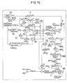
- the system of Figure 15 is an ANC/MST system for noise control in the interior of an automobile using a Psychoacoustic Masking Model unit PMM.
- the system of Figure 15 also includes a feedback system to produce a hybrid ANC/MST system, which combines the specific advantages of both feedforward and feedback systems.
- the feedback path can successfully reduce the noise signals in the interior of an automobile that diffusely and randomly intrude from outside and that do not correlate with the reference signal x(n) determined at a previously known noise source QS.
- the filter W with the transfer function W(z) from Figure 14 is replaced in the system of Figure 15 by an equivalent filter W 1 with a transfer function W FF (z), and which is part of the feedforward system that is equivalent to the system shown of Figure 14 .
- the system of Figure 15 includes a second filter W 2 with a transfer function W FB (Z) for the feedback path and a third unit LMS 3 for adaptive control of the filter coefficients of the filter W 2 using the Least Mean Square algorithm.
- the system of Figure 15 further includes a fourth filter S ⁇ 4 with a transfer function S ⁇ (z) and a fifth filter S ⁇ 5 with a transfer function S ⁇ (z), which are estimated using the method of system identification from the transfer function S(z) of the secondary path S.
- the error signal e(n) at the error microphone E is composed of the signal x(n) generated by the noise source QS and filtered on the primary path P with the transfer function P(z) from the noise x(n) and the signal y ' (n), which is the canceling signal y_sum(n) filtered by the transfer functions of the loudspeaker LS and the secondary path S.
- the reference signal z(n) is derived from the sum of the signal Music(n) from the music source MS and the signal FilteredWhiteNoise(n) from the white noise source NG evaluated with the Psychoacoustic Masking Model by filter F.
- the reference signal z(n) is added to the output signal y(n) of the filter W 1 weighted with 1-ß as well as to the output signal y FB (n) of the filter W 2 with the transfer function W FB (z) yields the signal y_sum(n) .
- the signal z(n) is also transformed via the Fast Fourier Transformation unit FFT 2 into the signal Z(w), which after filtering through the adaptive filter S ⁇ 3 with the transfer function S ⁇ (z) and subsequent Inverse Fast Fourier Transformation through the unit IFFT 1 is subtracted from the error signal e(n) to yield the signal e"(n) in comparison to the system of Figure 13 .
- the signal e"(n) in the time domain is converted to the signal E"( ⁇ ) in the frequency domain by the Fast Fourier Transformation unit FFT 1 .
- the signal E"( ⁇ ) is used as an input signal for the Psychoacoustic Masking Model unit PMM, which under consideration of the current masking through the noise at the site of the error microphone E generates the signal GAIN( ⁇ ), which is used to determine the reference signal z(n) through filter F.
- GAIN( ⁇ ) is converted by the Inverse Fast Fourier Transformation unit IFFT 2 to the time signal Gain(n) and constraint by the constraint unit C in such a way that the signal WhiteNoise(n) generated from the source NG is converted to the signal FilteredWhiteNoise(n) using the filter F, to which the new filter coefficient set Gain(n) is loaded.
- the FilteredWhiteNoise(n) signal matches the inaudible reference signal for system identification of the secondary path P (inaudible because the signal is below the audible threshold of the current noise signal).
- the reference signal z(n) can also include the useful signal Music(n), which is not essential for the function of the present system.
- the signal e ⁇ (n) is subtracted from the signal e''(n) generated from ß*y(n) with the transfer function S ⁇ (z) of the filter S ⁇ 2 to obtain the signal e'(n).
- This signal e'(n) is converted by the Fast Fourier Transformation unit FFT 3 to the signal E'( ⁇ ), and is used together with Z( ⁇ ) in the unit LMS 2 for adaptive control of the filter coefficients of the filters S ⁇ 1 , S ⁇ 2 , S ⁇ 3 , S ⁇ 4 and S ⁇ 5 with the Least Mean Square algorithm.
- the non-acoustic sensor NAS again generates an electric signal correlated with the noise signal, with which the signal f n (n) is obtained from the calculation unit CALC 1 .
- the signal generator SG generates the input signal x(n) for the filter W corresponding to the noise signal.
- the calculation unit CALC 2 determines the filter coefficients K(n) for the adaptive bandpass filter BP. Using the filter S ⁇ 1 with the transfer function S ⁇ (z), the signal x(n) is converted to the signal x'(n) and is then used together with the signal e'(n) filtered through the bandpass filter BP for control of the unit LMS 1 for adaptive control of the filter coefficients of the filter W using the Least Mean Square algorithm.
- the signal e'(n) is added to the signal derived from the signal y FB (n) filtered with the transfer function S(z) of the filter S ⁇ 5 to obtain the signal x FB (n) .
- the signal x FB (n) represents the input signal for the adaptive filter W 2 and is also used after conversion to the signal x' FB (n) through the filter S ⁇ 4 with the transfer function S(z) together with the signal e'(n) for accessing the circuit LMS 3 for adaptive control of the filter coefficients of the filter W 2 with the transfer function W FB (z) using the Least Mean Square algorithm.
- a psychoacoustic mask generation process executed by the Psychoacoustic Masking Model unit PMM of Figures 13-15 provides an implementation of the psychoacoustic model that simulates the masking effects of human hearing.
- the masking model used may be based on, e.g., the so-called Johnston Model or the MPEG model as described in the ISO MPEG1 standard.
- the exemplary implementations shown in Figures 16 and 17 use the MPEG model.
- the psychoacoustic mask modelling processes decribed herein my be implemented in a signal processor or in any other unit knomn running such process.
- the psychoacoustic mask modelling processes as shown in Figures 16 and 17 begin with Hann windowing the 512-sample time-domain input audio data frame 110 at step 204.
- the Hann windowing effectively centers the 512 samples between the previous samples and the subsequent samples, using a Hann window to provide a smooth taper. This reduces ringing edge artefacts that would otherwise be produced at step 206 when the time-domain audio data 110 is converted to the frequency domain using a 1024-point fast Fourier transform (FFT).
- FFT fast Fourier transform
- a value or entity is described as logarithmic or as being in the logarithmic-domain if it has been generated as the result of evaluating a logarithmic function.
- a logarithmic value or entity is exponentiated by the reverse operation, it is described as linear or as being in the linear-domain.
- PSD values are normalised to 96 dB at step 212. Steps 210 and 212 are omitted from the mask generation process 300 of Figure 17 .
- SPL sound pressure level
- scf max (n) is the maximum of the three scale factors of sub-band n within an MPEG1 L2 audio frame comprising 1152 samples
- X(k) is the PSD value of index k
- the summation over k is limited to values of k within sub-band n.
- the "-10 dB" term corrects for the difference between peak and RMS levels.
- the "96 dB" term is used in order to normalise L sb (n). It will be apparent that this improves upon the process 200 of Figure 16 by avoiding exponentiation.
- logarithm is approximated by four multiplications and two additions, providing a significant improvement in computational efficiency.
- the next step is to identify frequency components for masking.
- tonality of a masking component affects the masking threshold, tonal and non-tonal (noise) masking components are determined separately.
- a spectral line X(k) is deemed to be a local maximum if X k > X ⁇ k - 1 and X k ⁇ X ⁇ k + 1
- a local maximum X(k) is selected as a linear tonal masking component at step 304 if: X k ⁇ 10 - 0.7 ⁇ X ⁇ k + j
- the next step in either process is to identify and determine the intensity of non-tonal masking components within the bandwidth of critical sub-bands.
- a critical band For a given frequency, the smallest band of frequencies around that frequency which activate the same part of the basilar membrane of the human ear is referred to as a critical band.
- the critical bandwidth represents the ear's resolving power for simultaneous tones.
- the bandwidth of a sub-band varies with the center frequency of the specific critical band. As described in the MPEG-1 standard, 26 critical bands are used for a 48 kHz sampling rate.
- the non-tonal (noise) components are identified from the spectral lines remaining after the tonal components are removed as described above.
- the logarithmic powers of the remaining spectral lines within each critical band are converted to linear energy values, summed and then converted back into a logarithmic power value to provide the SPL of the new non-tonal component X noise (k) corresponding to that critical band.
- the number k is the index number of the spectral line nearest to the geometric mean of the critical band.
- X noise k ⁇ k X k for k in sub-band n. Only addition operations are used, and no exponential or logarithmic evaluations are required, providing a significant improvement in efficiency.
- the next step is to decimate the tonal and non-tonal masking components.
- Decimation is a procedure that is used to reduce the number of masking components that are used to generate the global masking threshold.
- logarithmic components X tonal (k) and non-tonal components X noise (k) are selected at step 220 for subsequent use in generating the masking threshold only if: X tonal k ⁇ L ⁇ T q k or X noise k ⁇ L ⁇ T q k respectively, where LTq(k) is the absolute threshold (or threshold in quiet) at the frequency of index k; threshold in quiet values in the logarithmic domain are provided in the MPEG-1 standard.
- Decimation is performed on two or more tonal components that are within a distance of less than 0.5 Bark, where the Bark scale is a frequency scale on which the frequency resolution of the ear is approximately constant, as described above (see also E. Zwicker, Subdivision of the Audible Frequency Range into Critical Bands, J. Acoustical Society of America, vol. 33, p. 248, February 1961 ).
- the tonal component with the highest power is kept while the smaller component(s) are removed from the list of selected tonal components.
- a sliding window in the critical band domain is used with a width of 0.5 Bark.
- the spectral data in the linear energy domain are converted into the logarithmic power domain at step 310.
- the evaluation of logarithms is performed using the efficient second-order approximation method described above. This conversion is followed by normalization to the reference level of 96 dB at step 212.
- the next step is to generate individual masking thresholds.
- individual masking thresholds Of the original 512 spectral data values, indexed by k, only a subset, indexed by i, is subsequently used to generate the global masking threshold, and the present step determines that subset by subsampling, as described in the ISO MPEG1 standard.
- n 126. Every tonal and non-tonal component is assigned an index i that most closely corresponds to the frequency of the corresponding spectral line in the original (i.e., before sub-sampling) spectral data.
- i is the index corresponding to a spectral line, at which the masking threshold is generated and j is that of a masking component
- z(i) is the Bark scale value of the i th spectral line while z(j) is that of the j th line
- terms of the form X[z(j)] are the SPLs of the (tonal or non-tonal) masking component.
- av referred to as the masking index
- av tonal - 1.525 - 0.275 ⁇ z j - 4.5 ⁇ dB
- the evaluation of the masking function vf is the most computationally intensive part of this step.
- the masking function can be categorized into two types: downward masking (when dz ⁇ 0) and upward masking (when dz ⁇ 0) wherein downward masking is considerably less significant than upward masking. Consequently, only upward masking is used in the mask generation process 300 of Figure 17 . Further analysis shows that the second term in the masking function for 1 ⁇ dz ⁇ 8 Bark is typically approximately one tenth of the first term, -17.dz. Consequently, the second term may be discarded.
- the masking index av is not modified from that used in the process 200 of Figure 16 , because it makes a significant contribution to the individual masking threshold LT and is not computationally demanding. After the individual masking thresholds have been generated, a global masking threshold is generated.
- the threshold in quiet LT q is offset by -12dB for bit rates ⁇ 96kbps per channel. It will be apparent that this step is computationally demanding due to the number of exponentials and logarithms that are evaluated.
- the largest tonal masking components LT tonal and of non-tonal masking components LT noise are identified. They are then compared with LT qx (i). The maximum of these three values is selected as the global masking threshold at the i th frequency sample. This reduces computational demands at the of occasional over allocation. As above, the threshold in quiet LT q is offset by -12dB for bit rates ⁇ 96kbps per channel.
- LT min (n) Min LTg i ⁇ dB ; f or f i in subband n , where f(i) is the i th frequency line within sub-band n.
- a minimum masking threshold LT min (n) is determined for every sub-band.
- the mask model sends the signal-to-mask ratio data SMRsb (n) for each sub-band n to a quantizer, which uses it to determine how to most effectively allocate the available data bits and quantize the spectral data, as described in the MPEG-1 standard.
- the beneficial effect in the examples above is derived from the consideration of the currently available noise level and its spectral attributes in the passenger area of an automobile, for which the test signal for determination of the transfer function of the secondary path is selected in such a way that it is inaudible to the passengers.
- the existing noise level can comprise unwanted obtrusive signals, such as wind disturbances, wheel-rolling sounds and undesirable noise, such as an acoustically modeled engine noise and, in some cases, simultaneously relayed music signals.
- undesirable noise such as an acoustically modeled engine noise and, in some cases, simultaneously relayed music signals.
- Use is made of the effect that inaudible information can be added to any given audio signal if the relevant psychoacoustic requirements are satisfied.
- the case presented here refers in particular to the psychoacoustic effects of masking.
Abstract
Description
- The invention refers to active noise control (ANC), including active motor sound tuning (MST), in particular for automobile and headphone applications.
- Noise is generally the term used to designate sound that does not contribute to the informational content of a receiver, but rather is perceived to be interfering with the audio quality of a useful signal. The evolution process of noise can be typically divided into three areas. These are the generation of the noise, its propagation (emission) and its perception. It can be seen that an attempt to successfully reduce noise is initially aimed at the source of the noise itself - for example, by attenuation and subsequently by suppression of the propagation of the noise signal. Nonetheless, the emission of noise signals cannot be reduced to the desired degree in many cases. In such cases the concept of removing undesirable sound by superimposing a compensation signal is applied.
- Known methods and systems for canceling or reducing emitted noise (ANC systems and methods) or undesirable interference signals - for example, through MST systems and methods, suppress unwanted noise by generating cancellation sound waves to superimpose on the unwanted signal, whose amplitude and frequency values are for the most part identical to those of the noise signal, but whose phase is shifted by 180 degrees in relation to the unwanted signal. In ideal situations, this method fully extinguishes the unwanted noise. This effect of targeted reduction in the sound level of a noise signal is often referred to as destructive interference.
- The term 'noise' refers in this case both to external acoustic sound waves - such as ambient noise or the motion sounds perceived in the passenger area of an automobile - and to acoustic sound waves initiated by mechanical vibrations, for example, the passenger area or drive of an automobile. If the sounds are undesirable, they are also referred to as noise. Whenever music or speech is relayed via an electro-acoustic system in an area exposed to audio signals, such as the passenger space of an automobile, the auditory perception of the signals is generally impaired by the background noise. The background noise can be caused by effects of the wind, the engine, the tires, fan and other units in the car, and therefore varies with the speed, road conditions and operating states in the automobile.
- So-called rear seat entertainment is becoming more and more popular in modern automobiles. This is offered by systems that provide high-quality audio signal reproduction and consequently demand greater consideration - or alternatively put - further reduction in the noise signals experienced. The option of focusing of audio signals toward individual persons is likewise demanded, normally through the medium of headphones. Known systems and methods therefore refer both to applications for the sonic field in the passenger area of an automobile and to transmission through headphones.
- Particularly, it has to be considered the acoustics present in automobiles due to undesirable noise - for example, components emitting from the engine or exhaust system. A noise signal generated by an engine generally includes a large number of sinusoidal components with amplitude and frequency values that are directly related to the revolving speed of the engine. These frequency components comprise both even and odd harmonic frequencies of the fundamental frequency (in revolutions per second) as well as half-order multiples or subharmonics.
- Thorough investigations have shown that a low, but constant noise level is not always evaluated positively. Instead, acceptable engine noises must satisfy strict requirements. Harmonic audio sequences are particularly favored. Since dissonance cannot be always excluded even for today's highly sophisticated mechanical engine designs, methods are employed to actively control engine noise in a positive manner. Methods of this kind are referred to as motor sound tuning (MST). To model the sonic behavior in these systems, for example, procedures are employed that use unwanted audio components for their cancellation at the source - for example, by means of a loudspeaker located in the intake duct of an engine for the acoustic cancellation signal. Methods are also known in which in a similar manner the sonic emission of the exhaust system of an automobile is modeled by the expunction of unwanted noise components.
- Active noise control methods and systems for noise reduction or sonic modeling are becoming increasingly more popular in recent times, in that modern digital signal processing and adaptive filter procedures are utilized. In typical applications, an input sensor - for example, a microphone - is used to derive a signal representing the unwanted noise that is generated by a source. This signal is then fed into the input of an adaptive filter and reshaped by the filter characteristics into an output signal that is used to control a cancellation actuator - for example, an acoustic loudspeaker or electromechanical vibration generator. The loudspeaker, or vibration generator, generates cancellation waves or vibrations that are superimposed on the unwanted noise signals or vibrations deriving from the source. The observed remaining noise level resulting from the superimposition of the noise control sound waves on the unwanted noise is measured by an error sensor, which generates a corresponding error feedback signal. This feedback signal is the basis used for modification of the parameters and characteristics of the adaptive filter in order to adaptively minimize the overall level of the observed noise or remainder noise signals. Feedback signal is the term used in digital signal processing for this responsive signal.
- A known algorithm that is commonly used in digital signal processing is an extension of the familiar Least Mean Squares (LMS) algorithm for minimization of the error feedback signal: the so-called Filtered-x LMS algorithm (FxLMS, cf. WIDROW, B., STEARNS, S. D. (1985): "Adaptive Signal Processing." Prentice-Hall Inc., Englewood Cliffs, NJ, USA. ISBN 0-13-004029-0). To implement this algorithm, a model of the acoustic transfer function is required between the active noise control actuator - in the case presented here, a loudspeaker - and the error sensor, in this case, a microphone. The transfer path between the active noise control actuator and the error sensor is also known as the secondary or error path, and the corresponding procedure for determining the transfer function as the system identification. In addition, an additional broadband auxiliary signal - for example, white noise, is transferred from the active noise control actuator to the error sensor using state-of-the-art methods to determine the relevant transfer function of the secondary path for the FxLMS algorithm. The filter coefficients of the transfer function of the secondary path are either defined when starting the ANC system and remain constant, or they are adaptively adjusted to the transfer conditions that change in time.
- A disadvantage of this approach is that the specified broadband auxiliary signal can be audible to the passengers in an automobile, depending on the prevailing ambient conditions. The signal can be perceived to be intrusive. In particular, an additional auxiliary signal of this kind will not satisfy the high demands placed on the quality (= least possible noise) of the interior acoustics and audio signal transmission for rear seat entertainment in high-value automobiles.
- It is a general need to provide a method and system which enable a test signal inaudible to human passengers (and therefore unobtrusive) in an automobile that is used to determine the transfer function of the secondary path required for the FxLMS algorithm.
- It is provided a system for active control of an unwanted noise signal at a listening site radiated by a noise source wherein the unwanted noise is transmitted to the listening site via a primary path having a primary path transfer function; said system comprising: a loudspeaker for radiating a cancellation signal to reduce or cancel the unwanted noise signal; said cancellation signal is transmitted from the loudspeaker to the listening site via a secondary path; an error microphone (E) at the listening site for determining through an error signal the level of achieved reduction; a first adaptive filter for generating the canceling signal by filtering a signal representative of the unwanted noise signal with a transfer function adapted to the quotient of the primary- and the secondary path (W(z)=P(z)/S(z)) transfer function using the signal representative of the unwanted noise signal and the error signal from the error microphone; and a reference generator for generating a reference signal which is supplied to the loudspeaker together with the canceling signal from the first adaptive filter; said reference signal has such an amplitude and/or frequency that it is masked for a human listener at the listening site by the unwanted noise signal and/or a wanted signal present at the listening site.
- A method for active control of an unwanted noise signal at a listening site radiated by a noise source wherein the unwanted noise is transmitted to the listening site via a primary path having a primary path transfer function comprises the steps of: radiating a cancellation signal to reduce or cancel the unwanted noise signal; said cancellation signal is transmitted from a loudspeaker to the listening site via a secondary path; determining through an error signal the level of achieved reduction at the listening site; first adaptive filtering for generating the canceling signal by filtering a signal representative of the unwanted noise signal with a transfer function adapted to the quotient of the primary- and the secondary path (W(z)=P(z)/S(z)) transfer function using the signal representative of the unwanted noise signal and the error signal; and generating a reference signal which is supplied to the loudspeaker together with the canceling signal from the first adaptive filtering step; said reference signal has an amplitude and/or frequency such that it is masked for a human listener at the listening site by the unwanted noise signal and/or a wanted signal present at the listening site.
- The invention can be better understood with reference to the following drawings and description. The components in the figures are not necessarily to scale, instead emphasis being placed upon illustrating the principles of the invention. Moreover, in the figures, like reference numerals designate corresponding parts. In the drawings:
- Figure 1
- is a block diagram of a system according to the present invention;
- Figure 2
- is a diagram illustrating the loudness as a function of the level of a sinusoidal tone and of a broadband noise signal;
- Figure 3
- is a diagram illustrating the masking of a tone by white noise;
- Figure 4
- is a diagram illustrating the masking effect in the frequency domain;
- Figure 5
- is a diagram illustrating the masked thresholds for critical frequency narrowband noise in the center frequencies of 250 Hz, 1 kHz and 4 kHz;
- Figure 6
- is a diagram illustrating the masking effect by sinusoidal tones;
- Figure 7
- is a diagram illustrating simultaneous, pre- and post-masking;
- Figure 8
- is a diagram illustrating the relationship of the loudness perception and the duration of a test tone pulse;
- Figure 9
- is a diagram illustrating the relationship of the masked threshold and the repetition rate of a test tone pulse.
- Figure 10
- is a diagram illustrating the post-masking effect in general;
- Figure 11
- is a diagram illustrating the post-masking effect in relation to the duration of the masker;
- Figure 12
- is a diagram illustrating the simultaneous masking by a complex tone;
- Figure 13
- is a block diagram showing an exemplary system for psychoacoustic system identification;
- Figure 14
- is a block diagram showing another exemplary system for psychoacoustic system identification;
- Figure 15
- is a block diagram showing just another exemplary system for psychoacoustic system identification;
- Figure 16
- is a flow diagram of process implementing the masking model evaluating a linear function; and
- Figure 16
- is a flow diagram of process implementing the masking model evaluating a logarithmic function.
- A feedforward control system is usually applied if a signal correlated with the unwanted noise that is to be reduced is used to drive the active noise control actuator (a loudspeaker in this case). In contrast, if the system response is measured and looped back, a feedback process is usually applied. Feedforward systems typically exhibit greater effectiveness in suppressing or reducing noise than feedback systems, particularly due to their ability of broadband reduction of noise. This is because feedforward systems enable noise to be prevented by initiating counteractions against evolving noises by evaluating the development of the noise signal. Feedback systems wait for the effects of noise to first become apparent before taking action. Active noise control does not take place until the sensor determines the noise effect. The advantage of feedback systems is that they can also operate effectively even if there is no signal correlated with the noise that can be used for control of the ANC system. For example, this applies to the use of ANC systems for headphones in which the headphones are worn in a space whose noise behavior is not previously known. Combinations of feedforward and feedback systems are also used in practical applications where possible in order to obtain a maximum level of noise reduction. Systems of this kinds are referred to hereafter as hybrid systems.
- Practical applications of feedforward control systems for active noise control are commonly adaptive in nature because the noise to reduce is typically subject to timing alterations in its sound level and spectral composition due to changing ambient conditions. In the example regarded here in automobiles, such changes in ambient conditions can be due to different driving speeds (wind noises, revolving tire noises), different load states of the engine, an open window and so on.
- It is known that a desired impulse response or transfer function of an unknown system can be adequately approximated using adaptive filters in a recursive method. Adaptive filters are taken to mean digital filters implemented with the aid of algorithms in digital signal processors, that adapt their filter coefficients to the input signal in accordance with the applicable algorithm. The unknown system in this case is assumed to be a linear, distorting system whose transfer function has to be determined. To find this transfer function, an adaptive system is connected in parallel to the unknown system.
- The so-called filtered-x LMS (FxLMS) algorithm is very often used in such cases, or variations of it. The structure of the filtered-x LMS algorithm is shown in
Figure 1 , which illustrates the block diagram of a typical digital ANC system that employs the filtered-x LMS (FxLMS) algorithm. For the sake of simplification, other components needed to actually realize such a system, such as amplifiers and analog-to-digital or digital-to-analog converters, are not shown here. - The system of
Figure 1 comprises a noise source QS, an error microphone E and a primary path P of the sonic transfer from the noise source S to the error microphone E with the transfer function P(z). The system ofFigure 1 also includes an adaptive filter W with a transfer function W(z), a loudspeaker LS for generating the noise control soundwaves and a secondary path S describing the sonic transfer from the loudspeaker LS to the error microphone E with the transfer function S(z). Also included in the system ofFigure 1 is a filter S^ the transfer function S^(z) of which is estimated from S(z) using the system identification method. The filter S^ is connected downstream of a function block LMS for the Least Mean Square algorithm for adaptive adjustment of the filter coefficients of the filter W. The LMS algorithm is an algorithm for approximation of the solution of the known least mean square problem. The algorithm works recursively - i.e., with each new data set the algorithm is rerun and the solution updated. The LMS algorithm offers a low degree of complexity and associated computing power requirements, numerical stability and low memory requirements. - The filtered-x LMS algorithm also has the advantage that it can be implemented, e.g., in a digital signal processor, with relatively little computing power. Two test signals are required as input parameters for the implementation of the FxLMS algorithm: a reference signal x(n), e.g., directly correlated with an external noise that affects the system, and an error signal e(n) that, e.g., is composed of the superimposition of the signal d(n) induced by the noise x(n) along the primary path P having a transfer function P(z), and a signal y'(n), which is obtained from the actuating signal y(n) through the loudspeaker LS and the secondary path S with the transfer function S(z) at the location of the error sensor. The actuating signal y(n) derives from filtering of the noise signal x(n) with a filter having the transfer function W(z). The name "filtered-x LMS" algorithm is based on the fact that not the noise x(n) directly in combination with the error signal e(n) is used for adaptation of the LMS control, but rather the signal x'(n) filtered with the transfer function S^(z) of filter S^, in order to compensate for the decorrelation, in particular between a broadband error signal x(n) and the error signal e(n), that arises on the primary path P from the loudspeaker LS to the error sensor E, (e.g., a microphone).
- IIR (Infinite Impulse Response) or FIR (Finite Impulse Response) filters are used as filters for the transfer functions W(z) and S^(z). FIR filters have a finite impulse response and work in discrete time steps that are usually determined by the sampling frequency of an analog signal. An n-th order FIR filter is defined by the differential equation

where y(n) is the output value at the time n, and is calculated from the sum of the last N sampled input values x(n-N) to x(n), for which the sum is weighted with filter coefficients bi. The desired transfer function is realized by specification of the filter coefficients bi (i= 0, 1...N). - Unlike FIR filters, output values that have already been computed are included in the analysis for IIR filters (recursive filters) having an infinite impulse response. Since the computed values can be very small after an infinite time, however, the computation can be interrupted in practice after a finite number of sample values n. The calculation scheme for an IIR filter is

where y(n) is the output value at the time n, and is calculated from the sum of the sampled input values x(n) weighted with the filter coefficients bi added to the sum of the output values y(n) weighted with the filter coefficients ai. The desired transfer function is again realized by specification of the filter coefficients ai and bi. - In contrast to FIR filters, IIR filters can be unstable here, but have greater selectivity for the same level of expenditure for their implementation. In practical applications the filter that best satisfies the relevant conditions under consideration of the requirements and associated computation is chosen.
- A disadvantage of the simple design of the filtered-x LMS algorithm as shown in
Figure 1 is that the quality of the system identification of the secondary path depends on the audio properties - for example, the sound level, bandwidth and spectral distribution of the actual noise signal x(n). - This has the effect in practical terms that the system identification of the secondary path is only carried out in narrowband and that additional noise components at the site of the desired noise cancellation, that are not contained in the noise x(n) dependent on the site of the determination of that noise x(n), are not considered by the filtered-x LMS algorithm. To conform with the causality condition, the site for determining the noise signal x(n) is located such that the resulting sonic propagation time corresponds to at least the period needed to compute the noise control signal for the loudspeaker LS. In practice a reference signal independent of the noise signal x(n) is generally used for system identification. This reference signal is added at a suitable position to the filtered-x LMS algorithm. This is illustrated schematically by the reference signal z(n) in
Figure 1 , which is added before the loudspeaker LS to the actuating signal for the noise control y(n), and which is used for system identification of the secondary path S. In this case, the signal y'(n) at the error microphone E is obtained from the transfer of the sum of the actuating signal for the noise control y(n) and the reference signal z(n) using the transfer function S(z) of the secondary path S. It is desirable here that the system identification - i.e., the determination of the transfer function S(z) of the secondary path S, be carried out with a signal with the largest possible bandwidth. As described above, a disadvantage of this approach is that this specified reference signal z(n) can be perceived to be intrusive for passengers in an automobile, depending on the prevailing ambient conditions. - The present invention seeks that the required reference signal z(n) for system identification of the secondary path S be produced in such a way that it is inaudible to the vehicle's passengers, taking the applicable noise level and its timing characteristics and spectral properties in the interior of an automobile or for headphones into consideration. To achieve this, physical variables are no longer be exclusively used. Instead, the psychoacoustic properties of the human ear are taken into account.
- Psychoacoustics deals with the audio perceptions that arise when a soundwave encounters the human ear. Based on human audible perceptions, frequency group creation in the inner ear, signal processing in the human inner ear and simultaneous and temporary masking effects in the time and frequency domains, a model can be produced to indicate what acoustic signals or what different combinations of acoustic signals are audible and inaudible to a person with normal hearing in the presence of noises. The threshold at which a test tone can be just heard in the presence of a noise (also known as a masker) is referred to as the masked threshold. In contrast, the minimum audible threshold is the term used to describe the threshold at the which a test tone can just be heard in a completely quiet environment. The area between minimum audible threshold and masked threshold is known as the masking area.
- The method described below uses psychoacoustic masking effects, which are the basis for the method of active noise control, particularly for generation of the reference signal z(n), which is inaudible to the passengers in the interior of an automobile as intended by the invention, depending on the existing conditions in the passenger area. The psychoacoustic masking model is used to generate the reference signal z(n). In this way, the system identification of the secondary path P is performed adaptively as claimed by the invention and is adjusted in realtime to changes in noise signals. As the noise signals in an automobile, that in accordance with the invention lead to masking i.e., inaudibility of the reference signal z(n), are subject to dynamic changes, both in regard to their spectral composition and to their timing characteristics, a psychoacoustic model considers the dependencies of the masking of the sonic level, of the spectral composition and of the timing.
- The basis for the modeling of the psychoacoustic masking are fundamental properties of the human ear, particularly of the inner ear. The inner ear is located in the so-called petruous bone and filled with incompressible lymphatic fluid. The inner ear is shaped like a snail (cochlea) with approximately 2½ turns. The cochlea in turn comprises parallel canals, the upper and lower canals separated by the basilar membrane. The organ of Corti rests on the membrane and contains the sensory cells of the human ear. If the basilar membrane is made to vibrate by soundwaves, nerve impulses are generated - i.e., no nodes or antinodes arise. This results in an effect that is crucial to hearing - the so-called frequency/location transformation on the basilar membrane, with which psychoacoustic masking effects and the refined frequency selectivity of the human ear can be explained.
- The human ear groups different soundwaves that occur in limited frequency bands together. These frequency bands are known as critical frequency groups or as critical bandwidth (CB). The basis of the CB is that the human ear compiles sounds in particular frequency bands as a common audible impression in regard to the psychoacoustic hearing impressions arising from the soundwaves. Sonic activities that occur within a frequency group affect each other differently than soundwaves occurring in different frequency groups. Two tones with the same level within the one frequency group, for example, are perceived as being quieter than if they were in different frequency groups.
- As a test tone is then audible within a masker when the energies are identical and the masker is in the frequency band whose center frequency is the frequency of the test tone, the sought bandwidth of the frequency groups can be determined. In the case of low frequencies, the frequency groups have a bandwidth of 100 Hz. For frequencies above 500 Hz, the frequency groups have a bandwidth of about 20% of the center frequency of the corresponding frequency group.
- If all critical frequency groups are placed side by side throughout the entire audible range, a hearing-oriented non-linear frequency scale is obtained, which is known as tonality and which has the unit "bark". It represents a distorted scaling of the frequency axis so that frequency groups have the same width of exactly 1 bark at every position. The non-linear relationship between frequency and tonality is rooted in the frequency/location transformation on the basilar membrane. The tonality function was defined in tabular and equation form by Zwicker (see Zwicker, E.; Fastl, H. Psychoacoustics - Facts and Models, 2nd edition, Springer-Verlag, Berlin/Heidelberg/New York, 1999) on the basis of masked threshold and loudness examinations. It can be seen that in the audible frequency range from 0 to 16 kHz exactly 24 frequency groups can be placed in series so that the associated tonality range is from 0 to 24 barks.
- Moreover, the terms loudness and sound intensity refer to the same quantity of impression and differ only in their units. They consider the frequency-dependent perception of the human ear. The psychoacoustic dimension "loudness" indicates how loud a sound with a specific level, a specific spectral composition and a specific duration is subjectively perceived. The loudness becomes twice as large if a sound is perceived to be twice as loud, which allows different soundwaves to be compared with each other in reference to the perceived loudness. The unit for evaluating and measuring loudness is a sone. One sone is defined as the perceived loudness of a tone having a loudness level of 40 phons - i.e., the perceived loudness of a tone that is perceived to have the same loudness as a sinus tone at a frequency of 1 kHz with a sound pressure level of 40 dB.
- In the case of medium-sized and high intensity values, an increase in intensity by 10 phones causes a two-fold increase in loudness. For low sound intensity, a slight rise in intensity causes the perceived loudness to be twice as large. The loudness perceived by humans depends on the sound pressure level, the frequency spectrum and the timing characteristics of the sound, and is also used for modeling masking effects. For example, there are also standardized measurement practices for measuring loudness according to DIN 45631 and ISO 532 B.
-
Figure 2 shows an example of the loudness N1kHz of a stationary sinus tone with a frequency of 1 kHz and the loudness NGAR of a stationary uniform excitation noise in relation to the sound level - i.e., for signals for which time effects have no influence on the perceived loudness. Uniform excitation noise (GAR) is defined as a noise that has the same sound intensity in each frequency bandwidth and therefore the same excitation.Figure 2 shows the loudness in sones in logarithmic scale versus sound pressure levels. For low sound pressure levels - i.e., when approaching the minimum audible threshold, the perceived loudness N of the tone falls dramatically. A relationship exists between loudness N and sound pressure level for high sound pressure levels - this relationship is defined by the equations shown in the figure. "I" refers to the sound intensity of the emitted tone in watts per m2, where I0 refers to the reference sound intensity of 10-12 watts per m2, which corresponds at center frequencies to roughly the minimum audible threshold (see below). It becomes clear from the continued behavior that the loudness N is a useful means of determining masking by complex noise signals, and is thus a necessary requirement for a model of psychoacoustic masking through spectrally complex, time-dependent sound waves. - If the
sound pressure level 1 is measured, which is needed to be able to just about perceive a tone as a function of the frequency, the so-called minimum audible threshold is obtained. Acoustic signals whose sound pressure levels are below the minimum audible threshold cannot be perceived by the human ear, even without the simultaneous presence of a noise signal. - The so-called masked threshold is defined as the threshold of perception for a test sound in the presence of a noisy signal. If the test sound is below this psychoacoustic threshold, the test sound is fully masked. This means that all information within the psychoacoustic range of the masking cannot be perceived - i.e., inaudible information can be added to any audio signal, even noise signals. The area between the masked threshold and minimum audible threshold is the so-called masking area, in which inserted signals cannot be perceived by the human ear. This aspect is utilized by the invention to add additional signal components (in the case shown here, the reference signal z(n) for system identification of the secondary path P) to the primary signal (in the case shown here, the noise signal x(n)) or to the total signal comprising the noise signal x(n) and, if applicable, music signals, in such a way that the reference signal z(n) can be detected by the receiver (in the case shown here, the error microphone E) and analyzed for subsequent processing, but is nonetheless inaudible to the human ear.
- Numerous investigations have demonstrated that masking effects can be measured for all kinds of human hearing. Unlike many other psychoacoustic impressions, differences between individuals are rare and can be ignored, meaning that a general psychoacoustic model of masking by sound can be produced. The psychoacoustic aspects of the masking are employed in the present invention in order to adapt the reference signal z(n) in realtime to the audio characteristics in such a manner that this acoustically transferred reference signal z(n) is inaudible, regardless of the currently existing noise level, its spectral composition and timing behavior. The noise level can be formed from ambient noise, interference, music or any combination of these.
- Here, a distinction is made between two major forms of masking, each of which causes different behavior of the masked thresholds. These are simultaneous masking in the frequency domain and masking in the time domain by timing effects of the masker along the time axis. Moreover, combinations of these two masking types are found in signals such as ambient noise or noise in general.
- Simultaneous masking means that a masking sound and useful signal occur at the same time. If the shape, bandwidth, amplitude and/or frequency of the masker changes in such a way that the frequently sinus-shaped test signals are just audible, the masked threshold can be determined for simultaneous masking throughout the entire bandwidth of the audible range - i.e., mainly for frequencies between 20 Hz and 20 kHz. This frequency range generally also represents the available bandwidth of audio equipment used in rearseat entertainment systems in automobiles, and therefore also the useful frequency range for the reference signal z(n) for system identification of the secondary path P.
-
Figure 3 shows the masking of a sinusoidal test tone by white noise. The sound intensity of a test tone just masked by white noise with thesound intensity 1WN is displayed in relation to its frequency where the minimum audible threshold is displayed as a dotted line. The minimum audible threshold of a sinus tone for masking by white noise is obtained as follows: below 500 Hz, the minimum audible threshold of the sinus tone is about 17 dB above the sound intensity of the white noise. Above 500 Hz the minimum audible threshold increases with about 10 dB per decade or about 3 dB per octave, corresponding to doubling the frequency. The frequency dependency of the minimum audible threshold is derived from the different critical bandwidth (CB) of the human ear at different center frequencies. - Since the sound intensity occurring in a frequency group is compiled in the perceived audio impression, a greater overall intensity is obtained in wider frequency groups at high frequencies for white noise whose level is independent of frequency. The loudness of the sound also rises correspondingly (i.e., the perceived loudness) and causes increased masked thresholds. This means that the purely physical dimensions (such as sound pressure levels of a masker, for example) are inadequate for the modeling of the psychoacoustic effects of masking - i.e., for deriving the masked threshold from dimensions, such as sound pressure level and intensity. Instead, psychoacoustic dimensions such as loudness N are used with the present invention. The spectral distribution and the timing characteristics of masking sounds play a major role, which is evident from the following figures.
- If the masked threshold is determined for narrowband maskers, such as sinus tones, narrowband noise or critical bandwidth noise, it is shown that the resulting spectral masked threshold is higher than the minimum audible threshold, even in areas in which the masker itself has no spectral components. Critical bandwidth noise is used in this case as narrowband noise, whose level is designated as LCB.
-
Figure 4 shows the masked thresholds of sinus tones measured as maskers due to critical bandwidth noise with a center frequency fc of 1 kHz, as well as of different sound pressure levels in relation to the frequency fT of the test tone with the level LT. The minimum audible threshold is displayed inFigure 3 by a dashed line. It can be seen fromFigure 4 that the peak values of the masked thresholds rise by 20 dB if the level of the masker also rises by 20 dB, and that they therefore vary linearly with the level LCB of the masking critical bandwidth noise. The lower edge of the measured masked thresholds - i.e., the masking in the direction of low frequencies lower than the center frequency fc, has a gradient of about -100 dB/octave that is independent of the level LCB of the masked thresholds. This large gradient is only reached on the upper edge of the masked threshold for levels LCB of the masker that are lower than 40 dB. With increases in the level LCB of the masker, the upper edge of the masked threshold becomes flatter and flatter, and the gradient is about - 25 dB/octave for an LCB of 100 dB. This means that the masking in the direction of higher frequencies compared to the center frequency fc of the masker extends far beyond the frequency range in which the masking sound is present. Hearing responds similarly for center frequencies other than 1 kHz for narrowband, critical bandwidth noise. The gradients of the upper and lower edges of the masked thresholds are practically independent of the center frequency of the masker - as seen inFigure 5 . -
Figure 5 shows the masked thresholds for maskers from critical bandwidth noise in the narrowband with a level LCB of 60 dB and three different center frequencies of 250 Hz, 1 kHz and 4 kHz. The apparently flatter flow of the gradient for the lower edge for the masker with the center frequency of 250 Hz is due to the minimum audible threshold, which applies at this low frequency even at higher levels. Effects such as those shown are likewise included in the implementation of a psychoacoustic model for the masking. The minimum audible threshold is again displayed inFigure 5 by a dashed line. - If the sinus-shaped test tone is masked by another sinus tone with a frequency of 1 kHz, masked thresholds such as shown in
Figure 6 are obtained in accordance with the frequency of the test tone and the level of the masker LM. As already described earlier, the fanning-out of the upper edge in relation to the level of the masker can be clearly seen, while the lower edge of the masked threshold is practically independent of frequency and level. The upper gradient is measured to be about -100 to -25 dB/octave in relation to the level of the masker, and about -100 dB/octave for the lower gradient. A difference of about 12 dB exists between the level LM of the masking tone and the maximum values of the masked thresholds Lr. This difference is significantly greater than the value obtained with critical bandwidth noise as the masker. This is because the intensities of the two sinus tones of the masker and of the test tone are added together at the same frequency, unlike the use of noise and a sinus tone as the test tone. Consequently, the tone is perceived much earlier - i.e., for low levels for the test tone. Moreover, when emitting two sinus tones at the same time, other effects (such as beats) arise, which likewise lead to increased perception or reduced masking. - Along with the described simultaneous masking, another psychoacoustic effect of masking is the so-called time masking. Two different kinds of time masking are distinguished: pre-masking refers to the situation in which masking effects occur already before the abrupt rise in the level of a masker. Post-masking describes the effect that occurs when the masked threshold does not immediately drop to the minimum audible threshold in the period after the fast fall in the level of a masker.
Figure 7 schematically shows both the pre- and post-masking, which are explained in greater detail further below in connection with the masking effect of tone impulses. - To determine the effects of the time pre- and post-masking, test tone impulses of a short duration must be used to obtain the corresponding time resolution of the masking effects. Here the minimum audible threshold and masked threshold are both dependent on the duration of a test tone. Two different effects are known in this regard. These refer to the dependency of the loudness impression on the duration of a test impulse (see
Figure 8 ) and the relationship between the repetition rate of short tone impulses and loudness impression (seeFigure 9 ). - The sound pressure level of a 20-ms impulse has to be increased by 10 dB in comparison to the sound pressure level of a 200-ms impulse in order to obtain the identical loudness impression. Upward of an impulse duration of 200 ms, the loudness of a tone impulse is independent of its duration. It is known for the human ear that processes with a duration of more than about 200 ms represent stationary processes. Psychoacoustically certifiable effects of the timing properties of sounds exist if the sounds are shorter than about 200 ms.
-
Figure 8 shows the dependency of the perception of a test tone impulse on its duration. The dotted lines denote the minimum audible thresholds TQ of test tone impulses for the frequencies fT = 200 Hz, 1 kHz and 4 kHz in relation to their duration, whereby the minimum audible thresholds rise with about 10 dB per decade for durations of the test tone of less than 200 ms. This behavior is independent of the frequency of the test tone, the absolute location of the lines for different frequencies fT of the test tone reflects the different minimum audible thresholds at these different frequencies. - The continuous lines represent the masked thresholds for masking a test tone by uniform masking noise (UMN) with a level LUMN of 40 dB and 60 dB. Uniform masking noise is defined to be such that it has a constant masked threshold throughout the entire audible range - i.e., for all frequency groups from 0 to 24 barks. In other words, the displayed characteristics of the masked thresholds are independent of the frequency fT of the test tone. Just like the minimum audible thresholds TQ, the masked thresholds also rise with about 10 dB per decade for durations of the test tone of less than 200 ms.
-
Figure 9 shows the dependency of the masked threshold on the repetition rate of a test tone impulse with thefrequency 3 kHz and a duration of 3 ms. Uniform masking noise is again the masker: it is modulated with a rectangular shape - i.e., it is switched on and off periodically. The examined modulation frequencies of the uniform masking noise are 5 Hz, 20 Hz and 100 Hz. The test tone is emitted with a subsequent frequency identical to the modulation frequency of the uniform masking noise. During the trial, the timing of the test tone impulses is correspondingly varied in order to obtain the time-related masked thresholds of the modulated noise. -
Figure 9 shows the shift in time of the test tone impulse along the abscissa standardized to the period duration TM of the masker. The ordinate shows the level of the test tone impulse at the calculated masked threshold. The dashed line represents the masked threshold of the test tone impulse for an unmodulated masker (i.e., continuously present masker with otherwise identical properties) as reference points. - The flatter gradient of the post-masking in
Figure 9 in comparison to the gradient of the pre-masking is clear to see. After activating the rectangular-shaped modulated masker, the masked threshold is exceeded for a short period. This effect is known as an overshoot. The maximum drop ΔL in the level of the masked threshold for modulated uniform masking noise in the pauses of the masker is reduced as expected in comparison to the masked threshold for stationary uniform masking noise in response to an increase in the modulation frequency of the uniform masking noise - in other words, the masked threshold of the test tone impulse can fall less and less during its lifetime to the minimum value specified by the minimum audible threshold. -
Figure 9 also illustrates that a masker already masks the test tone impulse before the masker is switched on at all. This effect is known - as already mentioned earlier - as pre-masking, and is based on the fact that loud tones and noises (i.e., with a high sound pressure level) can be processed more quickly by the hearing sense than quiet tones. The pre-masking effect is considerably less dominant than that of post-masking, and is therefore often omitted in the use of psychoacoustic models to simplify the corresponding algorithms. After disconnecting the masker, the audible threshold does not fall immediately to the minimum audible threshold, but rather reaches it after a period of about 200 ms. The effect can be explained by the slow settling of the transient wave on the basilar membrane of the inner ear. - On top of this, the bandwidth of a masker also has direct influence on the duration of the post-masking. The particular components of a masker associated with each individual frequency group cause post-masking as shown in
Figures 10 and 11 . -
Figure 10 shows the level characteristics LT of the masked threshold of a Gaussian impulse with a duration of 20 µs as the test tone that is present at a time tv after the end of a rectangular-shaped masker consisting of white noise with a duration of 500 ms, where the sound pressure level LWR of the white noise takes on the threelevels 40 dB, 60 dB and 80 dB. The post-masking of the masker comprising white noise can be measured without spectral effects, since the Gaussian-shaped test tone with a short duration of 20 µs in relation to the perceivable frequency range of the human ear also demonstrates a broadband spectral distribution similar to that of the white noise. The continuous curves inFigure 10 illustrate the characteristic of the post-processing determined by measurements. They in turn reach the value for the minimum audible threshold of the test tone (about 40 dB for the short test tone used in this case) after about 200 ms, independently of the level LWR of the masker.Figure 10 shows curves by means of dotted lines that correspond to an exponential falling away of the post-masking with a time constant of 10 ms. It can be seen that a simple approximation of this kind can only hold true for large levels of the masker, and that it never reflects the characteristic of the post-masking in the vicinity of the minimum audible threshold. - There is also a relationship between the post-masking and the duration of the masker. The dotted line in
Figure 11 shows the masked threshold of a Gaussian-shaped test tone impulse with a duration of 5 ms and a frequency of fT = 2 kHz as a function of the delay time td after the deactivation of a rectangular-shaped modulated masker comprising uniform masking noise with a level LUMN = 60 dB and a duration TM = 5ms. The continuous line shows the masked threshold for a masker with a duration of TM = 200 ms with parameters that are otherwise identical for test tone impulse and uniform masking noise. - The measured post-masking for the masker with the duration TM = 200 ms matches the post-masking also found for all maskers with a duration TM longer than 200 ms but with parameters that are otherwise identical. In the case of maskers of shorter duration, but with parameters that are otherwise identical (like spectral composition and level), the effect of post-masking is reduced, as is clear from the characteristics of the masked threshold for a duration TM = 5 ms of the masker. To use the psychoacoustic masking effects in algorithms and methods, such as the psychoacoustic masking model, it is also taken into consideration what resulting masking is obtained for grouped, complex or superimposed individual maskers. Simultaneous masking exists if different maskers occur at the same time. Only few real sounds are comparable to a pure sound, such as a sinus tone. In general, the tones emitted by musical instruments, as well as the sound arising from rotating bodies, such as engines in automobiles, have a large number of harmonics. Depending on the composition of the levels of the partial tones, the resulting masked thresholds can vary greatly.
-
Figure 12 shows the simultaneous masking for a complex sound. The masked threshold for the simultaneous masking of a sinus-shaped test tone is represented by the 10 harmonics of a 200-Hz sinus tone in relation to the frequency and level of the excitation. All harmonics have the same sound pressure level, but their phase positions are statistically distributed.Figure 12 shows the resulting masked thresholds for two cases in which all levels of the partial tones are either 40 dB or 60 dB. The fundamental tone and the first four harmonics are each located in separate frequency groups. This means that there is no additive superimposition of the masking parts of these complex sound components for the maximum value of the masked threshold. - However, the overlapping of the upper and lower edges and the depression resulting from the addition of the masking effects - which at its deepest point is still considerably higher than the minimum audible threshold - can be clearly seen. In contrast, most of the upper harmonics are within a critical bandwidth of the human hearing. A strong additive superimposition of the individual masked thresholds takes place in this critical bandwidth. As a consequence of this, the addition of simultaneous maskers cannot be calculated by adding their intensities together, but instead the individual specific loudness values must be added together to define the psychoacoustic model of the masking.
- To obtain the excitation distribution from the audio signal spectrum of time-varying signals, the known characteristics of the masked thresholds of sinus tones for masking by narrowband noise are used as the basis of the analysis. A distinction is made here between the core excitation (within a critical bandwidth) and edge excitation (outside a critical bandwidth). An example of this is the psychoacoustic core excitation of a sinus tone or a narrowband noise with a bandwidth smaller than the critical bandwidth matching the physical sound intensity. Otherwise, the signals are correspondingly distributed between the critical bandwidths masked by the audio spectrum. In this way, the distribution of the psychoacoustic excitation is obtained from the physical intensity spectrum of the received time-variable sound. The distribution of the psychoacoustic excitation is referred to as the specific loudness. The resulting overall loudness in the case of complex audio signals is found to be an integral over the specific loudness of all psychoacoustic excitations in the audible range along the tonal scale - i.e., in the range from 0 to 24 barks, and also exhibits corresponding time relations. Based on this overall loudness, the masked threshold is then created on the basis of the known relationship between loudness and masking, whereby the masked threshold drops to the minimum audible threshold in about 200 ms under consideration of time effects after termination of the sound within the relevant critical bandwidth (see also
Figure 10 , post-masking). - In this way, the psychoacoustic masking model is implemented under consideration of all masking effects discussed above. It can be seen from the preceding figures and explanations what masking effects are caused by sound pressure levels, spectral compositions and timing characteristics of noises, such as background noise, and how these effects can be utilized to manipulate a desired test signal adaptively and in real time for system identification of the secondary path S in such a way that it cannot be perceived by the listener in an environment of the kind described.
-
Figs. 13 to 15 below illustrate three examples for application of the psychoacoustic masking model with the present invention, particularly for psychoacoustic system identification of the secondary path S. The signal flow chart inFigure 13 illustrates an initial circuit in accordance with the invention for employment of the psychoacoustic masking model (PMM) for use in an ANC system for noise control in combination with headphones. No suitable reference signal correlated with the expected noise signal is available to this application, and therefore a feedback ANC system as described earlier is used. A feedforward ANC system requires the presence of a reference signal x(n) correlated with the expected noise signal, and that the causality condition is satisfied in such a way that the sensor for reception of this reference signal is always closer to the source of the noise signal to reduce than the error microphone E (seeFigure 1 ). This causality condition cannot be satisfied, particularly for headphones with freedom of movement in an unknown room. - An example of a system according to the invention as shown in
Figure 13 comprises a source QS generating a noise signal (e. g. a periodic noise signal), an error microphone E and a primary path P having a transfer function P(z) for sonic transmission from the noise source QS to the error microphone E. The system ofFigure 13 also comprises an adaptive filter W having a transfer function W(z), a loudspeaker LS connected upstream of the adaptive filter W for generating the cancellation soundwaves, and a secondary path S having a transfer function S(z) for sonic transmission from the loudspeaker LS to the error microphone E. - The system of
Figure 13 also comprises a first filter S^1 with a transfer function S^(z), a second filter S^2 with the transfer function S^(z) and a third filter S^3 with the transfer function S^(z), which were estimated from S(z) using the system identification method as described by S. Mitra, J. S. Kaiser, Handbook For Digital Signal Processing, Wiley and Sons 1993, pages 1085-1092 as well as a first control block LMS1 for adaptation of the filter coefficients of the filter W using the Least Mean Square algorithm, and a second control block LMS2 for adaptation of the filter coefficients of the first, second and third filters S^1, S^2 and S^3 using the Least Mean Square algorithm. The identical transfer functions S^(z) of the filters S^1, and S^2 are obtained in each case by simply copying the filter coefficients of filter S^3 determined during the adaptive system identification of the secondary path S carried out in realtime. - The system of
Figure 13 also comprises a first unit FFT1 and a second unit FFT2 for Fast Fourier Transformations of signals from the time domain to the frequency domain, as well as a first unit IFFT1 and a second unit IFFT2 for Inverse Fast Fourier Transformations of signals from the frequency domain to the time domain. Further, a Psychoacoustic Masking Model unit PMM, a constraint unit C for to avoid circular convolution products, a filter F and a source of white noise NG, and a music signal source MS. - An error signal e(n) at the error microphone E is composed, on one hand, of a signal d(n) resulting from a noise signal x(n) from the noise source QS transmitted over the primary path P having the transfer function P(z), and, on the other hand, of a signal y'(n), resulting from a canceling signal y_sum(n) supplied to the loudspeaker LS and then transmitted to the error microphone E over the secondary path S having the transfer function S(z). A reference signal z(n) is obtained by adding a signal Music(n) from a music source MS to a signal FilteredWhiteNoise(n) provided by the white-noise source NG via filter F. The reference signal z(n) is added to an output signal y(n) of the filter W, the sum of both said signals forming the signal y_sum(n).
- The reference signal z(n) is also supplied to the Fast Fourier Transformation unit FFT2 to be transformed into a signal Z(w), which after filtering through the adaptive filter S^3 with the transfer function S^(z) and subsequent Inverse Fast Fourier Transformation through the unit IFFT1 is subtracted from the error signal e(n) to yield the signal e'(n). The Fast Fourier Transformation unit FFT1 converts the signal e'(n) to a signal E'(w), which is supplied together with the signal Z(w) to the unit LMS2 for adaptive control of the filter coefficients of the filters S^1, S^2, and S^3 the filters using the Least Mean Square algorithm. The signal E'(ω) is also used as an input signal for the Psychoacoustic Masking Model unit PMM, which under consideration of the current masking through the noise at the site of the error microphone (i.e., the site of the headphones) generates a signal GAIN(w), which is used to determine the reference signal z(n). To do so, signal GAIN(ω) is converted by the unit for Inverse Fast Fourier Transformation IFFT2 to a time signal Gain(n) and set by the constraint unit C for avoiding circular convolution products, wherein the coefficients of the filter F is controlled by the signal Gain(n) which corresponds to the new filter coefficient set. The FilteredWhiteNoise(n) signal matches the inaudible reference signal for system identification of the secondary path P (inaudible because the reference signal is set below the audible threshold of the current noise signal).
- The reference signal z(n) may also include the useful signal Music(n) which, however, is not essential for the function of the present system. The signal e'(n) is added to the signal y'(n) derived from the signal y(n) through the transfer function S(z) of the filter S^2 in order to obtain a signal x^(n). The signal x^(n) represents the input signal for the adaptive filter W and is also used after processing by filter S^1 having the transfer function S(z) as signal x'^(n) supplied as well as a signal e'(n) to the unit LMS1 using the Least Mean Square algorithm for adaptive control of the filter coefficients of the filter W.
-
Figure 14 shows an ANC/MST system with noise control in the interior of an automobile using a Psychoacoustic Masking Model unit PMM. In contrast to the headphones application shown inFigure 13 , this application has a reference signal fn(n) correlated with the expected noise signal wherein a feedforward ANC/MST system is employed. The reference signal fn(n) is generated through a non-acoustic sensor, for example, by a piezoelectric transducer, or electro-acoustic transducer, a Hall element a rpm meter, arranged at the noise source site. Since the circuit shown inFigure 14 is used in an environment whose spatial characteristics (e.g., the interior of an automobile) are known, the causality condition required for a feedforward system, according to which the sensor for the reference signal fn(n) always has to be closer to the source of the noise signal to be reduced than the error microphone E, can be reliably satisfied by suitable positioning of these components. - The system of
Figure 14 includes the system ofFigure 13 and, further, a third unit FFT3for Fast Fourier Transformations of signals from the time domain to the frequency domain, a first calculation circuit CALC1 and a second calculation circuit CALC2. The system ofFigure 14 also features in addition to the system ofFigure 13 an adaptive bandpass filter BP and, as already mentioned above, a non-acoustic sensor NAS. - In the system of
Figure 14 , the error signal e(n) at the error microphone E is, like in the system ofFigure 13 , composed of the signals d(n) and y_sum(n). The reference signal z(n) is composed of the signal Music(n) from the music source MS and the signal FilterdeWhiteNoise(n). The reference signal z(n) is added to the output signal y(n) of the filter W weighted with 1-β yields the signal y_sum(n). The signal z(n) is again fed via the Fast Fourier Transformation unit FFT2 to obtain the signal Z(w), which after filtering through the adaptive filter S^3 and subsequent Inverse Fast Fourier Transformation through the unit IFFT1 is subtracted from the error signal e(n) to yield the signal e"(n) in comparison toFigure 13 . The signal e"(n) is converted to the signal E"(ω) by the Fast Fourier Transformation unit FFT1. The signal E"(ω) is used as an input signal for the Psychoacoustic Masking Model unit PMM, which under consideration of the current masking through the noise at the site of the error microphone generates the signal GAIN(ω) which is used to determine the reference signal z(n). To do so, signal GAIN(ω) in the frequency domain is transformed by the Inverse Fast Fourier Transformation unit IFFT2 to the signal Gain(n) in the time domain and constraint by the constraint unit C in such a way that the signal WhiteNoise(n) generated from the source NG is converted to the signal FilteredWhiteNoise(n) using the filter F, to which the new filter coefficient set Gain(n) is loaded. The FilteredWhiteNoise(n) signal matches the inaudible reference signal for system identification of the secondary path P (inaudible because the signal is below the audible threshold of the current noise signal). Moreover, the reference signal z(n) may also include the useful signal Music(n), which is not essential for the function of the present system. The signal e^(n) is subtracted from the signal e"(n) which is output by filter S^2 supplied with β·y(n) at its input. The signal e'(n) is transformed by the Fast Fourier Transformation unit FFT3 to the signal E'(ω), and is used together with Z(ω) in the unit LMS2 for adaptive control of the filter coefficients of the filters S^1, S^2, and S^3. - The non-acoustic sensor NAS generates an electrical signal correlated with the acoustic noise signal x(n); said electrical signal is supplied to the calculation circuit CALC1 from which the signal fn(n) is obtained. The signal generator SG then generates an input signal xc(n) for the filter W corresponding to the noise signal wherein xc(n)~x(n). The calculation unit CALC2 determines the filter coefficients K(n) for the adaptive bandpass filter BP. Using the filter S^1 with the transfer function S^(Z), the signal xc(n) is converted to the signal x'(n) and is then used together with the signal e'(n) filtered through the bandpass filter BP for control of the circuit LMS1 for adaptive control of the filter coefficients of the filter W using the Least Mean Square algorithm.
- The system of
Figure 15 is an ANC/MST system for noise control in the interior of an automobile using a Psychoacoustic Masking Model unit PMM. In addition to the feedforward system shown inFigure 14 , the system ofFigure 15 also includes a feedback system to produce a hybrid ANC/MST system, which combines the specific advantages of both feedforward and feedback systems. In particular, the feedback path can successfully reduce the noise signals in the interior of an automobile that diffusely and randomly intrude from outside and that do not correlate with the reference signal x(n) determined at a previously known noise source QS. - The filter W with the transfer function W(z) from
Figure 14 is replaced in the system ofFigure 15 by an equivalent filter W1 with a transfer function WFF(z), and which is part of the feedforward system that is equivalent to the system shown ofFigure 14 . In addition, the system ofFigure 15 includes a second filter W2 with a transfer function WFB(Z) for the feedback path and a third unit LMS3 for adaptive control of the filter coefficients of the filter W2 using the Least Mean Square algorithm. The system ofFigure 15 further includes a fourth filter S^4 with a transfer function S^(z) and a fifth filter S^5 with a transfer function S^(z), which are estimated using the method of system identification from the transfer function S(z) of the secondary path S. - As in the system of
Figure 14 , the error signal e(n) at the error microphone E is composed of the signal x(n) generated by the noise source QS and filtered on the primary path P with the transfer function P(z) from the noise x(n) and the signal y'(n), which is the canceling signal y_sum(n) filtered by the transfer functions of the loudspeaker LS and the secondary path S. The reference signal z(n) is derived from the sum of the signal Music(n) from the music source MS and the signal FilteredWhiteNoise(n) from the white noise source NG evaluated with the Psychoacoustic Masking Model by filter F. The reference signal z(n) is added to the output signal y(n) of the filter W1 weighted with 1-ß as well as to the output signal yFB(n) of the filter W2 with the transfer function WFB(z) yields the signal y_sum(n) . - The signal z(n) is also transformed via the Fast Fourier Transformation unit FFT2 into the signal Z(w), which after filtering through the adaptive filter S^3 with the transfer function S^(z) and subsequent Inverse Fast Fourier Transformation through the unit IFFT1 is subtracted from the error signal e(n) to yield the signal e"(n) in comparison to the system of
Figure 13 . The signal e"(n) in the time domain is converted to the signal E"(ω) in the frequency domain by the Fast Fourier Transformation unit FFT1. The signal E"(ω) is used as an input signal for the Psychoacoustic Masking Model unit PMM, which under consideration of the current masking through the noise at the site of the error microphone E generates the signal GAIN(ω), which is used to determine the reference signal z(n) through filter F. To do so, GAIN(ω) is converted by the Inverse Fast Fourier Transformation unit IFFT2 to the time signal Gain(n) and constraint by the constraint unit C in such a way that the signal WhiteNoise(n) generated from the source NG is converted to the signal FilteredWhiteNoise(n) using the filter F, to which the new filter coefficient set Gain(n) is loaded. - The FilteredWhiteNoise(n) signal matches the inaudible reference signal for system identification of the secondary path P (inaudible because the signal is below the audible threshold of the current noise signal). Moreover, the reference signal z(n) can also include the useful signal Music(n), which is not essential for the function of the present system. The signal e^(n) is subtracted from the signal e''(n) generated from ß*y(n) with the transfer function S^(z) of the filter S^2 to obtain the signal e'(n). This signal e'(n) is converted by the Fast Fourier Transformation unit FFT3 to the signal E'(ω), and is used together with Z(ω) in the unit LMS2 for adaptive control of the filter coefficients of the filters S^1, S^2, S^3, S^4 and S^5 with the Least Mean Square algorithm.
- The non-acoustic sensor NAS again generates an electric signal correlated with the noise signal, with which the signal fn(n) is obtained from the calculation unit CALC1. The signal generator SG generates the input signal x(n) for the filter W corresponding to the noise signal. The calculation unit CALC2 determines the filter coefficients K(n) for the adaptive bandpass filter BP. Using the filter S^1 with the transfer function S^(z), the signal x(n) is converted to the signal x'(n) and is then used together with the signal e'(n) filtered through the bandpass filter BP for control of the unit LMS1 for adaptive control of the filter coefficients of the filter W using the Least Mean Square algorithm. The signal e'(n) is added to the signal derived from the signal yFB(n) filtered with the transfer function S(z) of the filter S^5 to obtain the signal xFB(n) . The signal xFB(n) represents the input signal for the adaptive filter W2 and is also used after conversion to the signal x'FB(n) through the filter S^4 with the transfer function S(z) together with the signal e'(n) for accessing the circuit LMS3 for adaptive control of the filter coefficients of the filter W2 with the transfer function WFB(z) using the Least Mean Square algorithm.
- A psychoacoustic mask generation process executed by the Psychoacoustic Masking Model unit PMM of
Figures 13-15 provides an implementation of the psychoacoustic model that simulates the masking effects of human hearing. The masking model used may be based on, e.g., the so-called Johnston Model or the MPEG model as described in the ISO MPEG1 standard. The exemplary implementations shown inFigures 16 and17 use the MPEG model. The psychoacoustic mask modelling processes decribed herein my be implemented in a signal processor or in any other unit knomn running such process. - The psychoacoustic mask modelling processes as shown in
Figures 16 and17 begin with Hann windowing the 512-sample time-domain inputaudio data frame 110 atstep 204. The Hann windowing effectively centers the 512 samples between the previous samples and the subsequent samples, using a Hann window to provide a smooth taper. This reduces ringing edge artefacts that would otherwise be produced atstep 206 when the time-domain audio data 110 is converted to the frequency domain using a 1024-point fast Fourier transform (FFT). Atstep 208, an array of 512 energy values for respective frequency sub-bands is then generated from the symmetric array of 1024 FFT output values, according to:
where X (n) = XR(n)+iXI(n) is the FFT output of the nth spectral line. - In the following, a value or entity is described as logarithmic or as being in the logarithmic-domain if it has been generated as the result of evaluating a logarithmic function. When a logarithmic value or entity is exponentiated by the reverse operation, it is described as linear or as being in the linear-domain.
- In the process shown in
Figure 16 , the linear energy values E(n) are then converted into logarithmic power spectral density (PSD) values P(n) atstep 210, according to P(n) = 10log10E(n), and the linear energy values E(n) are not used again. The PSD values are normalised to 96 dB atstep 212.Steps mask generation process 300 ofFigure 17 . - The next step in both processes is to generate sound pressure level (SPL) values for each sub-band. In the process of
Figure 16 , an SPL value Lsb(n) is generated for each sub-band n atstep 214, according to:
and
where scfmax(n) is the maximum of the three scale factors of sub-band n within an MPEG1 L2 audio frame comprising 1152 samples, X(k) is the PSD value of index k, and the summation over k is limited to values of k within sub-band n. The "-10 dB" term corrects for the difference between peak and RMS levels. - In the
mask modelling process 300 ofFigure 17 , Lsb(n) is calculated atstep 302, according to:
where X(k) is the linear energy value of index k. The "96 dB" term is used in order to normalise Lsb(n). It will be apparent that this improves upon theprocess 200 ofFigure 16 by avoiding exponentiation. Moreover, the efficiency of generating the SPL values is significantly improved by approximating the logarithm by a second order Taylor expansion. Specifically, representing the argument of the logarithm as Ipt, this is first normalised by determining x such that:
- Using a second order Taylor expansion,

the logarithm can be approximated as:
- Thus the logarithm is approximated by four multiplications and two additions, providing a significant improvement in computational efficiency.
- The next step is to identify frequency components for masking. As the tonality of a masking component affects the masking threshold, tonal and non-tonal (noise) masking components are determined separately.
- First, local maxima are identified. A spectral line X(k) is deemed to be a local maximum if

- In the
process 200 ofFigure 16 , a local maximum X(k) thus identified is selected as a logarithmic tonal masking component atstep 216 if:
where j is a searching range that varies with k. If X(k) is found to be a tonal component, then its value is replaced by:
- All spectral lines within the examined frequency range are then set to -∞dB.
- In the
mask modelling process 300 ofFigure 17 , a local maximum X(k) is selected as a linear tonal masking component atstep 304 if:
- If X(k) is found to be a tonal component, then its value is replaced by:

- All spectral lines within the examined frequency range are then set to 0.
- The next step in either process is to identify and determine the intensity of non-tonal masking components within the bandwidth of critical sub-bands. For a given frequency, the smallest band of frequencies around that frequency which activate the same part of the basilar membrane of the human ear is referred to as a critical band. The critical bandwidth represents the ear's resolving power for simultaneous tones. The bandwidth of a sub-band varies with the center frequency of the specific critical band. As described in the MPEG-1 standard, 26 critical bands are used for a 48 kHz sampling rate. The non-tonal (noise) components are identified from the spectral lines remaining after the tonal components are removed as described above.
- At
step 218 of theprocess 200 ofFigure 16 , the logarithmic powers of the remaining spectral lines within each critical band are converted to linear energy values, summed and then converted back into a logarithmic power value to provide the SPL of the new non-tonal component Xnoise(k) corresponding to that critical band. The number k is the index number of the spectral line nearest to the geometric mean of the critical band. - In the
mask modelling process 300 ofFigure 17 , the energy of the remaining spectral lines within each critical band are summed atstep 306 to provide the new non-tonal component Xnoise(k) corresponding to that critical band:
for k in sub-band n. Only addition operations are used, and no exponential or logarithmic evaluations are required, providing a significant improvement in efficiency. - The next step is to decimate the tonal and non-tonal masking components. Decimation is a procedure that is used to reduce the number of masking components that are used to generate the global masking threshold.
- In the
process 200 ofFigure 16 , logarithmic components Xtonal (k) and non-tonal components Xnoise (k) are selected atstep 220 for subsequent use in generating the masking threshold only if:
respectively, where LTq(k) is the absolute threshold (or threshold in quiet) at the frequency of index k; threshold in quiet values in the logarithmic domain are provided in the MPEG-1 standard. - Decimation is performed on two or more tonal components that are within a distance of less than 0.5 Bark, where the Bark scale is a frequency scale on which the frequency resolution of the ear is approximately constant, as described above (see also E. Zwicker, Subdivision of the Audible Frequency Range into Critical Bands, J. Acoustical Society of America, vol. 33, p. 248, February 1961). The tonal component with the highest power is kept while the smaller component(s) are removed from the list of selected tonal components. For this operation, a sliding window in the critical band domain is used with a width of 0.5 Bark.
- In the
mask modelling process 300 ofFigur 17 , linear components are selected atstep 308 only if:
where LTqE(k) are taken from a linear-domain absolute threshold table pre-generated from the logarithmic domain absolute threshold table LTq(k) according to:
where the "-96" term represents denormalization. - After denormalization, the spectral data in the linear energy domain are converted into the logarithmic power domain at
step 310. In contrast to step 206 of the prior art process, the evaluation of logarithms is performed using the efficient second-order approximation method described above. This conversion is followed by normalization to the reference level of 96 dB atstep 212. - Having selected and decimated masking components, the next step is to generate individual masking thresholds. Of the original 512 spectral data values, indexed by k, only a subset, indexed by i, is subsequently used to generate the global masking threshold, and the present step determines that subset by subsampling, as described in the ISO MPEG1 standard.
- The number of lines n in the subsampled frequency domain depends on the sampling rate. For a sampling rate of 48 kHz, n = 126. Every tonal and non-tonal component is assigned an index i that most closely corresponds to the frequency of the corresponding spectral line in the original (i.e., before sub-sampling) spectral data.
- The individual masking thresholds of both tonal and non-tonal components, LTtonal and LTnoise, are then given by the following expressions:


where i is the index corresponding to a spectral line, at which the masking threshold is generated and j is that of a masking component; z(i) is the Bark scale value of the ith spectral line while z(j) is that of the jth line; and terms of the form X[z(j)] are the SPLs of the (tonal or non-tonal) masking component. The term av, referred to as the masking index, is given by:

vf is a masking function of the masking component and comprises different lower and upper slopes, depending on the distance in Bark scale dz, dz = z(i)-z(i) - In the
process 200 ofFigure 16 , individual masking thresholds are calculated atstep 222 using a masking function vf given by:


where X[z(j)] is the SPL of the masking component with index j. No masking threshold is generated if dz < -3 Bark, or dz > 8 Bark. - The evaluation of the masking function vf is the most computationally intensive part of this step. The masking function can be categorized into two types: downward masking (when dz < 0) and upward masking (when dz ≥ 0) wherein downward masking is considerably less significant than upward masking. Consequently, only upward masking is used in the
mask generation process 300 ofFigure 17 . Further analysis shows that the second term in the masking function for 1 ≤ dz < 8 Bark is typically approximately one tenth of the first term, -17.dz. Consequently, the second term may be discarded. - Accordingly, the
mask generation process 300 ofFigure 17 generates individual masking thresholds atstep 312 using a single expression for the masking function vf, as follows:
- The masking index av is not modified from that used in the
process 200 ofFigure 16 , because it makes a significant contribution to the individual masking threshold LT and is not computationally demanding. After the individual masking thresholds have been generated, a global masking threshold is generated. - In the
process 200 ofFigure 16 , the global masking threshold LTg(i) at the ith frequency sample is generated atstep 224 by summing the powers corresponding to the individual masking thresholds and the threshold in quiet, according to:
where m is the total number of tonal masking components, and n is the total number of non-tonal masking components. The threshold in quiet LTq is offset by -12dB for bit rates ≥ 96kbps per channel. It will be apparent that this step is computationally demanding due to the number of exponentials and logarithms that are evaluated. - In the
mask generation process 300 ofFigure 17 , these evaluations are avoided and smaller terms are not used. The global marking threshold LTg(i) at the ith frequency sample is generated atstep 314 by comparing the powers corresponding to the individual masking thresholds and the threshold in quiet, as follows:
- The largest tonal masking components LTtonal and of non-tonal masking components LTnoise are identified. They are then compared with LTqx(i). The maximum of these three values is selected as the global masking threshold at the ith frequency sample. This reduces computational demands at the of occasional over allocation. As above, the threshold in quiet LTq is offset by -12dB for bit rates ≥ 96kbps per channel.
- Finally, signal-to-mask ratio values are calculated at
step 226 of both processes. First, the minimum masking level LTmin(n) in sub-band n is determined by the following expression:
where f(i) is the ith frequency line within sub-band n. A minimum masking threshold LTmin(n) is determined for every sub-band. The signal-to-mask ratio for every sub-band n is then generated by subtracting the minimum masking threshold of that sub-band from the corresponding SPL value:
- The mask model sends the signal-to-mask ratio data SMRsb (n) for each sub-band n to a quantizer, which uses it to determine how to most effectively allocate the available data bits and quantize the spectral data, as described in the MPEG-1 standard.
- The beneficial effect in the examples above is derived from the consideration of the currently available noise level and its spectral attributes in the passenger area of an automobile, for which the test signal for determination of the transfer function of the secondary path is selected in such a way that it is inaudible to the passengers. The existing noise level can comprise unwanted obtrusive signals, such as wind disturbances, wheel-rolling sounds and undesirable noise, such as an acoustically modeled engine noise and, in some cases, simultaneously relayed music signals. Use is made of the effect that inaudible information can be added to any given audio signal if the relevant psychoacoustic requirements are satisfied. The case presented here refers in particular to the psychoacoustic effects of masking.
- Further benefits can be derived from the aspect that the method of psychoacoustic masking responds adaptively to the current noise level, and that audio signals (such as music) at the same time are not necessary in order to obtain the desired masking effect.
- Although various examples to realize the invention have been disclosed, it will be apparent to those skilled in the art that various changes and modifications can be made which will achieve some of the advantages of the invention without departing from the spirit and scope of the invention. It will be obvious to those reasonably skilled in the art that other components performing the same functions may be suitably substituted. Such modifications to the inventive concept are intended to be covered by the appended claims.
Claims (38)
- A system for active control of an unwanted noise signal at a listening site radiated by a noise source wherein the unwanted noise is transmitted to the listening site via a primary path having a primary path transfer function; said system comprising:a loudspeaker for radiating a cancellation signal to reduce or cancel the unwanted noise signal; said cancellation signal is transmitted from the loudspeaker to the listening site via a secondary path;an error microphone (E) at the listening site for determining through an error signal the level of achieved reduction;a first adaptive filter for generating the canceling signal by filtering a signal representative of the unwanted noise signal with a transfer function adapted to the primary path transfer function using the signal representative of the unwanted noise signal and the error signal from the error microphone; anda reference generator for generating a reference signal which is supplied to the loudspeaker together with the canceling signal from the first adaptive filter; said reference signal has such an amplitude and/or frequency that it is masked for a human listener at the listening site by the unwanted noise signal and/or a wanted signal present at the listening site.
- The system of claim 1 wherein amplitude and/or frequency of the reference signal are determined by a psychoacoustic masking model unit which models masking in human hearing in the error signal from the error microphone.
- The system of claim 2 wherein the psychoacoustic masking model unit models temporal masking.
- The system of claim 2 or 3 wherein the psychoacoustic masking model unit models spectral masking.
- The system of one of claims 2, 3, or 4 wherein the psychoacoustic masking model unit is operated in the frequency domain.
- The system of one of claims 1-5 wherein said first adaptive filter adapts according to the Least Mean Square (LMS) algorithm.
- The system of claim 7 or 8 wherein said first filter adapts according to the filtered X Least Mean Square (filtered x-LMS) algorithm.
- The system of claim 7 further comprising a second adaptive filter having a transfer function modeling the transfer function of the secondary path; said second adaptive filter being connected to the first adaptive filter for filtering the signal representative of the unwanted noise signal used for the adaptation of the first adaptive filter.
- The system of claim 8 wherein said second adaptive filter adapts according to the Least Mean Square (LMS) algorithm.
- The system of one of claims 1-9 wherein the signal representative of the unwanted noise signal supplied to the first adaptive filter is derived from the error signal and the signal output by the first adaptive filter and filtered by a third adaptive filter having a transfer function modeling the transfer function of the secondary path.
- The system of claim 10 wherein the signal representative of the unwanted noise signal supplied to the first adaptive filter is derived further from the reference signal filtered with a fourth adaptive filter having a transfer function modeling the transfer function of the secondary path.
- The system of claim 11 wherein the fourth filter is operated in the frequency domain; said fourth filter having a time-to-frequency converter connected upstream and a frequency-to-time converter connected downstream.
- The system of one of claims 1-12 wherein the signal representing the unwanted noise signal supplied to the first adaptive filter is derived from a non-acoustic sensor; said non-acoustic sensor providing a sensor signal and being arranged near the unwanted-noise source.
- The system of claim 13 further comprising a fundamental calculation unit connected downstream of the non-acoustic sensor for calculating a fundamental signal from the sensor signal and a signal generator connected downstream of the fundamental calculation unit for generating the signal representative of the unwanted noise signal from the fundamental signal.
- The system of claim 14 further comprising a band pass filter having filter coefficients for filtering the error signal supplied to the first adaptive filter; said filter coefficients are controlled by a coefficient calculation unit connected downstream of the fundamental calculation unit.
- The system of one of claims 1-15 wherein the reference signal includes a wanted signal provided by a wanted-signal source.
- The system of one of claim 1-16 wherein the signal output by the first adaptive filter is split into two partial signals multiplied with weighting factors; one of said partial signals is supplied to the loudspeaker and the other is supplied to a fifth adaptive filter modeling the secondary path whose output signal is added to the error signal.
- The system of claim 17 wherein the sum of said weights is one.
- The system of one of claims 1-18 further comprising a sixth adaptive filter for modeling the primary path; said sixth adaptive filter providing an output signal supplied to the loudspeaker and being supplied with the sum of its output signal and the reference signal.
- A method for active control of an unwanted noise signal at a listening site radiated by a noise source wherein the unwanted noise is transmitted to the listening site via a primary path having a primary path transfer function; said method comprising the steps of:radiating a cancellation signal to reduce or cancel the unwanted noise signal; said cancellation signal is transmitted from a loudspeaker to the listening site via a secondary path;determining through an error signal the level of achieved reduction at the listening site;first adaptive filtering for generating the canceling signal by filtering a signal representative of the unwanted noise signal with a transfer function adapted to the primary path transfer function using the signal representative of the unwanted noise signal and the error signal; andgenerating a reference signal which is supplied to the loudspeaker together with the canceling signal from the first adaptive filtering step; said reference signal has an amplitude and/or frequency such that it is masked for a human listener at the listening site by the unwanted noise signal and/or a wanted signal present at the listening site.
- The method of claim 20 wherein amplitude and/or frequency of the reference signal are determined by a psychoacoustic masking modeling step which models masking in human hearing in the error signal.
- The method of claim 21 wherein the psychoacoustic masking modeling step models temporal masking.
- The method of claim 20 or 21 wherein the psychoacoustic masking modeling step models spectral masking.
- The method of one of claims 21, 22, or 23 wherein the psychoacoustic masking modeling step is performed in the frequency domain.
- The method of one of claims 20-24 wherein said first adaptive filter step adapts according to the Least Mean Square (LMS) algorithm.
- The method of claim 25 wherein said first step adapts according to the filtered X Least Mean Square (filtered x-LMS) algorithm.
- The system of claim 26 further comprising a second adaptive filtering step using a transfer function modeling the transfer function of the secondary path; said second adaptive filter being connected to the first adaptive filter for filtering the signal representative of the unwanted noise signal used for the adaptation of the first adaptive filter.
- The method of claim 27 wherein said second adaptive filter adapts according to the Least Mean Square (LMS) algorithm.
- The method of one of claims 20-28 wherein the signal representative of the unwanted noise signal used in the first adaptive filtering step is derived from the error signal and the signal output by the first adaptive filtering step and filtered in a third adaptive filtering step having a transfer function modeling the transfer function of the secondary path.
- The method of claim 29 wherein the signal representative of the unwanted noise signal used in the first adaptive filtering step is derived further from the reference signal filtered in a fourth adaptive filtering step having a transfer function modeling the transfer function of the secondary path.
- The method of claim 30 wherein the fourth filtering step is performed in the frequency domain; said fourth filtering step includes a time-to-frequency conversion step in advance to and a frequency-to-time conversion step following said fourth filtering step.
- The method of one of claims 20-31 wherein the signal representing the unwanted noise signal used in the first adaptive filtering step is derived from a non-acoustic sensor; said non-acoustic sensor providing a sensor signal and being arranged near the unwanted-noise source.
- The method of claim 32 further comprising a fundamental calculation step for calculating a fundamental signal from the sensor signal and a signal generation step for generating the signal representative of the unwanted noise signal from the fundamental signal.
- The method of claim 33 further comprising a band pass filtering step using filter coefficients for filtering the error signal used in the first adaptive filtering step; said filter coefficients are controlled by a coefficient calculation step using the fundamental signal.
- The method of one of claims 20-34 wherein the reference signal includes a wanted signal provided by a wanted-signal source.
- The method of one of claim 20-35 wherein the signal output by the first adaptive filtering step is split into two partial signals multiplied with weighting factors; one of said partial signals is supplied to the loudspeaker and the other is used by a fifth adaptive filtering step modeling the secondary path whose output signal is added to the error signal.
- The system of claim 36 wherein the sum of said weights is one.
- The system of one of claims 20-37 further comprising a sixth adaptive filtering step for modeling the primary path; said sixth adaptive filtering step providing an output signal supplied to the loudspeaker and being input with the sum of its output signal and the reference signal.
Priority Applications (7)
| Application Number | Priority Date | Filing Date | Title |
|---|---|---|---|
| EP07000818.0A EP1947642B1 (en) | 2007-01-16 | 2007-01-16 | Active noise control system |
| CA2617369A CA2617369C (en) | 2007-01-16 | 2008-01-08 | Active noise control system |
| JP2008003045A JP5184896B2 (en) | 2007-01-16 | 2008-01-10 | Active noise control system |
| KR1020080004247A KR101160159B1 (en) | 2007-01-16 | 2008-01-15 | Active noise control system |
| CN2008100036756A CN101354885B (en) | 2007-01-16 | 2008-01-16 | Active noise control system |
| US12/015,219 US8199923B2 (en) | 2007-01-16 | 2008-01-16 | Active noise control system |
| JP2012158559A JP2012230412A (en) | 2007-01-16 | 2012-07-17 | Active noise control system |
Applications Claiming Priority (1)
| Application Number | Priority Date | Filing Date | Title |
|---|---|---|---|
| EP07000818.0A EP1947642B1 (en) | 2007-01-16 | 2007-01-16 | Active noise control system |
Publications (2)
| Publication Number | Publication Date |
|---|---|
| EP1947642A1 true EP1947642A1 (en) | 2008-07-23 |
| EP1947642B1 EP1947642B1 (en) | 2018-06-13 |
Family
ID=38739432
Family Applications (1)
| Application Number | Title | Priority Date | Filing Date |
|---|---|---|---|
| EP07000818.0A Not-in-force EP1947642B1 (en) | 2007-01-16 | 2007-01-16 | Active noise control system |
Country Status (6)
| Country | Link |
|---|---|
| US (1) | US8199923B2 (en) |
| EP (1) | EP1947642B1 (en) |
| JP (2) | JP5184896B2 (en) |
| KR (1) | KR101160159B1 (en) |
| CN (1) | CN101354885B (en) |
| CA (1) | CA2617369C (en) |
Cited By (67)
| Publication number | Priority date | Publication date | Assignee | Title |
|---|---|---|---|---|
| GB2455826A (en) * | 2007-12-21 | 2009-06-24 | Wolfson Microelectronics Plc | Adaptive noise cancellation |
| WO2010033103A1 (en) * | 2008-09-19 | 2010-03-25 | Otis Elevator Company | Actively controlled noise cancellation system for an elevator cab |
| EP2216774A1 (en) | 2009-01-30 | 2010-08-11 | Harman Becker Automotive Systems GmbH | Adaptive noise control system |
| US8077873B2 (en) | 2009-05-14 | 2011-12-13 | Harman International Industries, Incorporated | System for active noise control with adaptive speaker selection |
| US8135140B2 (en) | 2008-11-20 | 2012-03-13 | Harman International Industries, Incorporated | System for active noise control with audio signal compensation |
| US8189799B2 (en) | 2009-04-09 | 2012-05-29 | Harman International Industries, Incorporated | System for active noise control based on audio system output |
| US8199924B2 (en) | 2009-04-17 | 2012-06-12 | Harman International Industries, Incorporated | System for active noise control with an infinite impulse response filter |
| CN102905209A (en) * | 2011-07-26 | 2013-01-30 | Akg声学有限公司 | Noise reducing sound reproduction |
| EP2551845A1 (en) * | 2011-07-26 | 2013-01-30 | Harman Becker Automotive Systems GmbH | Noise reducing sound reproduction |
| RU2479120C2 (en) * | 2011-05-20 | 2013-04-10 | Учреждение Российской академии наук Институт прикладной астрономии РАН | Radio receiver for detection of broadband signals with phase manipulation |
| US8718289B2 (en) | 2009-01-12 | 2014-05-06 | Harman International Industries, Incorporated | System for active noise control with parallel adaptive filter configuration |
| CN104081452A (en) * | 2012-01-31 | 2014-10-01 | 哈曼贝克自动系统股份有限公司 | Method of adjusting an active noise cancelling (ANC) system |
| US20140307888A1 (en) * | 2013-04-10 | 2014-10-16 | Cirrus Logic, Inc. | Systems and methods for multi-mode adaptive noise cancellation for audio headsets |
| WO2014172019A1 (en) * | 2013-04-17 | 2014-10-23 | Cirrus Logic, Inc. | Systems and methods for hybrid adaptive noise cancellation |
| WO2014172021A1 (en) * | 2013-04-17 | 2014-10-23 | Cirrus Logic, Inc. | Systems and methods for adaptive noise cancellation by biasing anti-noise level |
| US9014387B2 (en) | 2012-04-26 | 2015-04-21 | Cirrus Logic, Inc. | Coordinated control of adaptive noise cancellation (ANC) among earspeaker channels |
| US9020158B2 (en) | 2008-11-20 | 2015-04-28 | Harman International Industries, Incorporated | Quiet zone control system |
| EP2884488A1 (en) * | 2013-12-16 | 2015-06-17 | Harman Becker Automotive Systems GmbH | Active noise control system |
| US9066176B2 (en) | 2013-04-15 | 2015-06-23 | Cirrus Logic, Inc. | Systems and methods for adaptive noise cancellation including dynamic bias of coefficients of an adaptive noise cancellation system |
| US9076427B2 (en) | 2012-05-10 | 2015-07-07 | Cirrus Logic, Inc. | Error-signal content controlled adaptation of secondary and leakage path models in noise-canceling personal audio devices |
| US9076431B2 (en) | 2011-06-03 | 2015-07-07 | Cirrus Logic, Inc. | Filter architecture for an adaptive noise canceler in a personal audio device |
| US9082387B2 (en) | 2012-05-10 | 2015-07-14 | Cirrus Logic, Inc. | Noise burst adaptation of secondary path adaptive response in noise-canceling personal audio devices |
| US9094744B1 (en) | 2012-09-14 | 2015-07-28 | Cirrus Logic, Inc. | Close talk detector for noise cancellation |
| US9107010B2 (en) | 2013-02-08 | 2015-08-11 | Cirrus Logic, Inc. | Ambient noise root mean square (RMS) detector |
| US9106989B2 (en) | 2013-03-13 | 2015-08-11 | Cirrus Logic, Inc. | Adaptive-noise canceling (ANC) effectiveness estimation and correction in a personal audio device |
| US9123321B2 (en) | 2012-05-10 | 2015-09-01 | Cirrus Logic, Inc. | Sequenced adaptation of anti-noise generator response and secondary path response in an adaptive noise canceling system |
| US9142205B2 (en) | 2012-04-26 | 2015-09-22 | Cirrus Logic, Inc. | Leakage-modeling adaptive noise canceling for earspeakers |
| US9142207B2 (en) | 2010-12-03 | 2015-09-22 | Cirrus Logic, Inc. | Oversight control of an adaptive noise canceler in a personal audio device |
| US9208771B2 (en) | 2013-03-15 | 2015-12-08 | Cirrus Logic, Inc. | Ambient noise-based adaptation of secondary path adaptive response in noise-canceling personal audio devices |
| US9215749B2 (en) | 2013-03-14 | 2015-12-15 | Cirrus Logic, Inc. | Reducing an acoustic intensity vector with adaptive noise cancellation with two error microphones |
| US9214150B2 (en) | 2011-06-03 | 2015-12-15 | Cirrus Logic, Inc. | Continuous adaptation of secondary path adaptive response in noise-canceling personal audio devices |
| US9264808B2 (en) | 2013-06-14 | 2016-02-16 | Cirrus Logic, Inc. | Systems and methods for detection and cancellation of narrow-band noise |
| US9294836B2 (en) | 2013-04-16 | 2016-03-22 | Cirrus Logic, Inc. | Systems and methods for adaptive noise cancellation including secondary path estimate monitoring |
| US9318090B2 (en) | 2012-05-10 | 2016-04-19 | Cirrus Logic, Inc. | Downlink tone detection and adaptation of a secondary path response model in an adaptive noise canceling system |
| US9319784B2 (en) | 2014-04-14 | 2016-04-19 | Cirrus Logic, Inc. | Frequency-shaped noise-based adaptation of secondary path adaptive response in noise-canceling personal audio devices |
| US9318094B2 (en) | 2011-06-03 | 2016-04-19 | Cirrus Logic, Inc. | Adaptive noise canceling architecture for a personal audio device |
| US9319781B2 (en) | 2012-05-10 | 2016-04-19 | Cirrus Logic, Inc. | Frequency and direction-dependent ambient sound handling in personal audio devices having adaptive noise cancellation (ANC) |
| US9325821B1 (en) | 2011-09-30 | 2016-04-26 | Cirrus Logic, Inc. | Sidetone management in an adaptive noise canceling (ANC) system including secondary path modeling |
| US9324311B1 (en) | 2013-03-15 | 2016-04-26 | Cirrus Logic, Inc. | Robust adaptive noise canceling (ANC) in a personal audio device |
| US9369557B2 (en) | 2014-03-05 | 2016-06-14 | Cirrus Logic, Inc. | Frequency-dependent sidetone calibration |
| US9369798B1 (en) | 2013-03-12 | 2016-06-14 | Cirrus Logic, Inc. | Internal dynamic range control in an adaptive noise cancellation (ANC) system |
| US9368099B2 (en) | 2011-06-03 | 2016-06-14 | Cirrus Logic, Inc. | Bandlimiting anti-noise in personal audio devices having adaptive noise cancellation (ANC) |
| EP3038102A1 (en) * | 2014-12-24 | 2016-06-29 | Magneti Marelli S.p.A. | Method for performing an active profiling of a sound emitted by an engine and corresponding profiling system |
| US9392364B1 (en) | 2013-08-15 | 2016-07-12 | Cirrus Logic, Inc. | Virtual microphone for adaptive noise cancellation in personal audio devices |
| US9414150B2 (en) | 2013-03-14 | 2016-08-09 | Cirrus Logic, Inc. | Low-latency multi-driver adaptive noise canceling (ANC) system for a personal audio device |
| US9467776B2 (en) | 2013-03-15 | 2016-10-11 | Cirrus Logic, Inc. | Monitoring of speaker impedance to detect pressure applied between mobile device and ear |
| US9479860B2 (en) | 2014-03-07 | 2016-10-25 | Cirrus Logic, Inc. | Systems and methods for enhancing performance of audio transducer based on detection of transducer status |
| US9478212B1 (en) | 2014-09-03 | 2016-10-25 | Cirrus Logic, Inc. | Systems and methods for use of adaptive secondary path estimate to control equalization in an audio device |
| US9491537B2 (en) | 2011-07-26 | 2016-11-08 | Harman Becker Automotive Systems Gmbh | Noise reducing sound reproduction system |
| US9552805B2 (en) | 2014-12-19 | 2017-01-24 | Cirrus Logic, Inc. | Systems and methods for performance and stability control for feedback adaptive noise cancellation |
| US9578432B1 (en) | 2013-04-24 | 2017-02-21 | Cirrus Logic, Inc. | Metric and tool to evaluate secondary path design in adaptive noise cancellation systems |
| US9578415B1 (en) | 2015-08-21 | 2017-02-21 | Cirrus Logic, Inc. | Hybrid adaptive noise cancellation system with filtered error microphone signal |
| US9609416B2 (en) | 2014-06-09 | 2017-03-28 | Cirrus Logic, Inc. | Headphone responsive to optical signaling |
| US9620101B1 (en) | 2013-10-08 | 2017-04-11 | Cirrus Logic, Inc. | Systems and methods for maintaining playback fidelity in an audio system with adaptive noise cancellation |
| US9635480B2 (en) | 2013-03-15 | 2017-04-25 | Cirrus Logic, Inc. | Speaker impedance monitoring |
| US9646595B2 (en) | 2010-12-03 | 2017-05-09 | Cirrus Logic, Inc. | Ear-coupling detection and adjustment of adaptive response in noise-canceling in personal audio devices |
| US9648410B1 (en) | 2014-03-12 | 2017-05-09 | Cirrus Logic, Inc. | Control of audio output of headphone earbuds based on the environment around the headphone earbuds |
| US9666176B2 (en) | 2013-09-13 | 2017-05-30 | Cirrus Logic, Inc. | Systems and methods for adaptive noise cancellation by adaptively shaping internal white noise to train a secondary path |
| US9704472B2 (en) | 2013-12-10 | 2017-07-11 | Cirrus Logic, Inc. | Systems and methods for sharing secondary path information between audio channels in an adaptive noise cancellation system |
| US9824677B2 (en) | 2011-06-03 | 2017-11-21 | Cirrus Logic, Inc. | Bandlimiting anti-noise in personal audio devices having adaptive noise cancellation (ANC) |
| US10013966B2 (en) | 2016-03-15 | 2018-07-03 | Cirrus Logic, Inc. | Systems and methods for adaptive active noise cancellation for multiple-driver personal audio device |
| US10026388B2 (en) | 2015-08-20 | 2018-07-17 | Cirrus Logic, Inc. | Feedback adaptive noise cancellation (ANC) controller and method having a feedback response partially provided by a fixed-response filter |
| US10181315B2 (en) | 2014-06-13 | 2019-01-15 | Cirrus Logic, Inc. | Systems and methods for selectively enabling and disabling adaptation of an adaptive noise cancellation system |
| US10219071B2 (en) | 2013-12-10 | 2019-02-26 | Cirrus Logic, Inc. | Systems and methods for bandlimiting anti-noise in personal audio devices having adaptive noise cancellation |
| US10382864B2 (en) | 2013-12-10 | 2019-08-13 | Cirrus Logic, Inc. | Systems and methods for providing adaptive playback equalization in an audio device |
| US10468048B2 (en) | 2011-06-03 | 2019-11-05 | Cirrus Logic, Inc. | Mic covering detection in personal audio devices |
| CN113763916A (en) * | 2021-09-07 | 2021-12-07 | 吉林大学 | Nonlinear hybrid active noise control method and control system |
Families Citing this family (104)
| Publication number | Priority date | Publication date | Assignee | Title |
|---|---|---|---|---|
| US8535236B2 (en) * | 2004-03-19 | 2013-09-17 | Fraunhofer-Gesellschaft Zur Foerderung Der Angewandten Forschung E.V. | Apparatus and method for analyzing a sound signal using a physiological ear model |
| US8964997B2 (en) * | 2005-05-18 | 2015-02-24 | Bose Corporation | Adapted audio masking |
| US8270625B2 (en) * | 2006-12-06 | 2012-09-18 | Brigham Young University | Secondary path modeling for active noise control |
| US8503669B2 (en) * | 2008-04-07 | 2013-08-06 | Sony Computer Entertainment Inc. | Integrated latency detection and echo cancellation |
| US8218783B2 (en) * | 2008-12-23 | 2012-07-10 | Bose Corporation | Masking based gain control |
| US8229125B2 (en) * | 2009-02-06 | 2012-07-24 | Bose Corporation | Adjusting dynamic range of an audio system |
| EP2401872A4 (en) * | 2009-02-25 | 2012-05-23 | Conexant Systems Inc | Speaker distortion reduction system and method |
| CN102387942A (en) * | 2009-04-15 | 2012-03-21 | 日本先锋公司 | Active vibration noise control device |
| US8223985B2 (en) * | 2009-04-22 | 2012-07-17 | General Electric Company | Masking of pure tones within sound from a noise generating source |
| US8737636B2 (en) | 2009-07-10 | 2014-05-27 | Qualcomm Incorporated | Systems, methods, apparatus, and computer-readable media for adaptive active noise cancellation |
| US8750530B2 (en) * | 2009-09-15 | 2014-06-10 | Native Instruments Gmbh | Method and arrangement for processing audio data, and a corresponding corresponding computer-readable storage medium |
| US8019092B2 (en) * | 2009-10-27 | 2011-09-13 | Savannah Marketing Group Inc. | Aural device with white noise generator |
| JP5294085B2 (en) * | 2009-11-06 | 2013-09-18 | 日本電気株式会社 | Information processing apparatus, accessory apparatus thereof, information processing system, control method thereof, and control program |
| US8385559B2 (en) * | 2009-12-30 | 2013-02-26 | Robert Bosch Gmbh | Adaptive digital noise canceller |
| CN101819766B (en) * | 2010-01-15 | 2012-06-27 | 浙江万里学院 | Multi-channel active noise control method for abating noises |
| TWI381370B (en) * | 2010-02-11 | 2013-01-01 | 私立中原大學 | Active noise reduction system |
| EP2362381B1 (en) * | 2010-02-25 | 2019-12-18 | Harman Becker Automotive Systems GmbH | Active noise reduction system |
| US8320581B2 (en) * | 2010-03-03 | 2012-11-27 | Bose Corporation | Vehicle engine sound enhancement |
| CN101833949B (en) * | 2010-04-26 | 2012-01-11 | 浙江万里学院 | Active noise control method for eliminating and reducing noise |
| EP2395501B1 (en) * | 2010-06-14 | 2015-08-12 | Harman Becker Automotive Systems GmbH | Adaptive noise control |
| CN102907019B (en) * | 2010-07-29 | 2015-07-01 | 英派尔科技开发有限公司 | Acoustic noise management through control of electrical device operations |
| CN101976560B (en) * | 2010-09-29 | 2012-09-05 | 哈尔滨工业大学 | Method for improving performance of feedforward narrow-band active noise control system |
| JP5503023B2 (en) * | 2011-01-06 | 2014-05-28 | パイオニア株式会社 | Active vibration noise control apparatus, active vibration noise control method, and active vibration noise control program |
| US9299337B2 (en) | 2011-01-11 | 2016-03-29 | Bose Corporation | Vehicle engine sound enhancement |
| US8848936B2 (en) | 2011-06-03 | 2014-09-30 | Cirrus Logic, Inc. | Speaker damage prevention in adaptive noise-canceling personal audio devices |
| EP2597638B1 (en) * | 2011-11-22 | 2020-06-03 | Harman Becker Automotive Systems GmbH | Tunable active noise control |
| US9129586B2 (en) | 2012-09-10 | 2015-09-08 | Apple Inc. | Prevention of ANC instability in the presence of low frequency noise |
| JP6015279B2 (en) * | 2012-09-20 | 2016-10-26 | アイシン精機株式会社 | Noise removal device |
| US9135920B2 (en) * | 2012-11-26 | 2015-09-15 | Harman International Industries, Incorporated | System for perceived enhancement and restoration of compressed audio signals |
| FR2999711B1 (en) * | 2012-12-13 | 2015-07-03 | Snecma | METHOD AND DEVICE FOR ACOUSTICALLY DETECTING A DYSFUNCTION OF AN ENGINE EQUIPPED WITH AN ACTIVE NOISE CONTROL. |
| CN103905959A (en) * | 2012-12-26 | 2014-07-02 | 上海航空电器有限公司 | Active noise control device based on pilot headset |
| US9959852B2 (en) | 2013-01-18 | 2018-05-01 | Bose Corporation | Vehicle engine sound extraction |
| US9031248B2 (en) * | 2013-01-18 | 2015-05-12 | Bose Corporation | Vehicle engine sound extraction and reproduction |
| US9240176B2 (en) | 2013-02-08 | 2016-01-19 | GM Global Technology Operations LLC | Active noise control system and method |
| US9831898B2 (en) * | 2013-03-13 | 2017-11-28 | Analog Devices Global | Radio frequency transmitter noise cancellation |
| US9515629B2 (en) * | 2013-05-16 | 2016-12-06 | Apple Inc. | Adaptive audio equalization for personal listening devices |
| JP6325663B2 (en) * | 2013-06-21 | 2018-05-16 | ブリュール アンド ケーア サウンド アンド バイブレーション メジャーメント アクティーゼルスカブ | Method for determining noise sound contribution of noise source of motor driven moving body |
| US9837066B2 (en) * | 2013-07-28 | 2017-12-05 | Light Speed Aviation, Inc. | System and method for adaptive active noise reduction |
| US9607602B2 (en) | 2013-09-06 | 2017-03-28 | Apple Inc. | ANC system with SPL-controlled output |
| JP6125389B2 (en) * | 2013-09-24 | 2017-05-10 | 株式会社東芝 | Active silencer and method |
| WO2015065882A1 (en) | 2013-10-28 | 2015-05-07 | 3M Innovative Properties Company | Adaptive frequency response, adaptive automatic level control and handling radio communications for a hearing protector |
| CN104064177B (en) * | 2014-05-05 | 2017-09-08 | 浙江银江研究院有限公司 | Active noise controlling method based on quantum particle swarm optimization |
| KR101557228B1 (en) | 2014-05-14 | 2015-10-02 | 인하대학교 산학협력단 | Method for active noise control of vehicle and apparatus thereof |
| CN104063610A (en) * | 2014-07-01 | 2014-09-24 | 中冶南方工程技术有限公司 | Simulation noise source and original noise sensor transmitting model identifying method |
| CN104123438A (en) * | 2014-07-01 | 2014-10-29 | 中冶南方工程技术有限公司 | Method for recognizing second noise transmission channel model |
| AT516086A1 (en) * | 2014-07-23 | 2016-02-15 | Siemens Ag Oesterreich | Method and device for determining the absolute speed of a rail vehicle |
| EP2996112B1 (en) * | 2014-09-10 | 2018-08-22 | Harman Becker Automotive Systems GmbH | Adaptive noise control system with improved robustness |
| US10121464B2 (en) * | 2014-12-08 | 2018-11-06 | Ford Global Technologies, Llc | Subband algorithm with threshold for robust broadband active noise control system |
| US9734816B2 (en) * | 2015-02-02 | 2017-08-15 | Panasonic Intellectual Property Management Co., Ltd. | Noise reduction device |
| EP3170173B1 (en) * | 2015-05-08 | 2019-04-17 | Huawei Technologies Co. Ltd. | Active noise cancellation device |
| ES2849260T3 (en) | 2015-05-15 | 2021-08-17 | Nureva Inc | System and method for embedding additional information in a sound mask noise signal |
| KR20160149548A (en) * | 2015-06-18 | 2016-12-28 | 현대자동차주식회사 | Apparatus and method of masking vehicle noise masking |
| US9728179B2 (en) * | 2015-10-16 | 2017-08-08 | Avnera Corporation | Calibration and stabilization of an active noise cancelation system |
| US9812114B2 (en) * | 2016-03-02 | 2017-11-07 | Cirrus Logic, Inc. | Systems and methods for controlling adaptive noise control gain |
| EP3226581B1 (en) * | 2016-03-31 | 2020-06-10 | Harman Becker Automotive Systems GmbH | Automatic noise control for a vehicle seat |
| CN106356072A (en) * | 2016-09-26 | 2017-01-25 | 郑州云海信息技术有限公司 | Electronic denoising method and system thereof |
| US10586521B2 (en) * | 2016-10-31 | 2020-03-10 | Cirrus Logic, Inc. | Ear interface detection |
| TWI604439B (en) | 2017-01-17 | 2017-11-01 | 瑞昱半導體股份有限公司 | Noise cancellation device and noise cancellation method |
| US10163432B2 (en) * | 2017-02-23 | 2018-12-25 | 2236008 Ontario Inc. | Active noise control using variable step-size adaptation |
| DE102017107538A1 (en) * | 2017-04-07 | 2018-10-11 | Ipetronik Gmbh & Co. Kg | Control device and method for noise reduction of auxiliary equipment for a vehicle |
| US10224017B2 (en) * | 2017-04-26 | 2019-03-05 | Ford Global Technologies, Llc | Active sound desensitization to tonal noise in a vehicle |
| CN109300465B (en) * | 2017-07-24 | 2022-05-13 | 比亚迪股份有限公司 | New energy vehicle and active noise reduction method and system thereof |
| FR3069932B1 (en) * | 2017-08-01 | 2019-09-06 | Hyvibe | PERFECTED SOUND RESTITUTION FROM A DEVICE WITH VIBRANT MECHANICAL ACTUATOR |
| WO2019084480A1 (en) * | 2017-10-26 | 2019-05-02 | Bose Corporation | Adaptive feedback noise cancellation of a sinusoidal disturbance |
| CN109854230B (en) * | 2017-11-30 | 2022-05-10 | 中国石油天然气股份有限公司 | Well testing method and device |
| US11308932B2 (en) | 2017-12-20 | 2022-04-19 | Harman International Industries, Incorporated | Virtual test environment for active noise management systems |
| CN108366320A (en) * | 2018-01-08 | 2018-08-03 | 联创汽车电子有限公司 | Vehicle-mounted feedforward active noise reduction system |
| US10339912B1 (en) * | 2018-03-08 | 2019-07-02 | Harman International Industries, Incorporated | Active noise cancellation system utilizing a diagonalization filter matrix |
| CN108564963B (en) * | 2018-04-23 | 2019-10-18 | 百度在线网络技术(北京)有限公司 | Method and apparatus for enhancing voice |
| WO2020012235A1 (en) | 2018-07-13 | 2020-01-16 | Bosch Car Multimedia Portugal, S.A. | Active noise cancelling system, based on a frequency domain audio control unit, and respective method of operation |
| US11252517B2 (en) * | 2018-07-17 | 2022-02-15 | Marcos Antonio Cantu | Assistive listening device and human-computer interface using short-time target cancellation for improved speech intelligibility |
| US10796692B2 (en) * | 2018-07-17 | 2020-10-06 | Marcos A. Cantu | Assistive listening device and human-computer interface using short-time target cancellation for improved speech intelligibility |
| US10410620B1 (en) | 2018-08-31 | 2019-09-10 | Bose Corporation | Systems and methods for reducing acoustic artifacts in an adaptive feedforward control system |
| US10706834B2 (en) | 2018-08-31 | 2020-07-07 | Bose Corporation | Systems and methods for disabling adaptation in an adaptive feedforward control system |
| US10741165B2 (en) | 2018-08-31 | 2020-08-11 | Bose Corporation | Systems and methods for noise-cancellation with shaping and weighting filters |
| US10629183B2 (en) | 2018-08-31 | 2020-04-21 | Bose Corporation | Systems and methods for noise-cancellation using microphone projection |
| CN109346052B (en) * | 2018-09-03 | 2022-11-18 | 江苏大学 | Device and method for optimizing sound quality in vehicle by utilizing active noise reduction |
| US10553197B1 (en) * | 2018-10-16 | 2020-02-04 | Harman International Industries, Incorporated | Concurrent noise cancelation systems with harmonic filtering |
| CN111128208B (en) * | 2018-10-30 | 2023-09-05 | 比亚迪股份有限公司 | Portable exciter |
| CN109961773B (en) * | 2019-01-15 | 2023-03-21 | 华南理工大学 | Active noise reduction method for rotary mechanical order noise |
| CN110010117B (en) * | 2019-04-11 | 2021-06-25 | 湖北大学 | Voice active noise reduction method and device |
| US20210110843A1 (en) | 2019-05-28 | 2021-04-15 | Utility Associates, Inc. | Systems and methods for detecting a gunshot |
| US10891936B2 (en) * | 2019-06-05 | 2021-01-12 | Harman International Industries, Incorporated | Voice echo suppression in engine order cancellation systems |
| CN110598278B (en) * | 2019-08-27 | 2023-04-07 | 中国舰船研究设计中心 | Evaluation method for acoustic characteristics of ship mechanical system |
| CN110728970B (en) * | 2019-09-29 | 2022-02-25 | 东莞市中光通信科技有限公司 | Method and device for digital auxiliary sound insulation treatment |
| CN110767249A (en) * | 2019-10-31 | 2020-02-07 | 重庆长安汽车股份有限公司 | Loudness saliency-based automobile transmission system transient impact noise evaluation method |
| CN111161699B (en) * | 2019-12-30 | 2023-04-28 | 广州心与潮信息科技有限公司 | Method, device and equipment for masking environmental noise |
| CN113365176B (en) * | 2020-03-03 | 2023-04-28 | 华为技术有限公司 | Method and device for realizing active noise elimination and electronic equipment |
| CN113066466B (en) * | 2021-03-16 | 2023-07-18 | 西北工业大学 | Audio injection regulation sound design method based on band-limited noise |
| CN112863470B (en) * | 2021-03-16 | 2023-04-18 | 吉讴工业设计(上海)有限公司 | Active noise reduction device and method for large-current noise in electric automobile |
| JP7241117B2 (en) * | 2021-03-18 | 2023-03-16 | 本田技研工業株式会社 | sound control device |
| CN113112981B (en) * | 2021-03-26 | 2024-04-09 | 清华大学苏州汽车研究院(相城) | Road noise active control method |
| KR102300425B1 (en) * | 2021-05-20 | 2021-09-09 | 주식회사 아큐리스 | Noise masking method through variable masking sound level conversion |
| CN113280912B (en) * | 2021-06-09 | 2024-03-05 | 湛江港(集团)股份有限公司 | Multi-dimensional noise monitoring system for industrial enterprise factory |
| CN113593515B (en) * | 2021-07-15 | 2023-11-24 | 江南大学 | Wide-narrow band hybrid active noise control system for coping with frequency offset |
| TWI790737B (en) | 2021-09-06 | 2023-01-21 | 宏碁股份有限公司 | Electronic system with heat dissipation and feedforward active noise control function |
| WO2023077252A1 (en) * | 2021-11-02 | 2023-05-11 | 华为技术有限公司 | Fxlms structure-based active noise reduction system, method, and device |
| TWI806260B (en) * | 2021-11-26 | 2023-06-21 | 宏碁股份有限公司 | Electronic system with heat dissipation and feedforward active noise control function with wind pressure compensation |
| CN114241800B (en) * | 2022-02-28 | 2022-05-27 | 天津市北海通信技术有限公司 | Intelligent stop reporting auxiliary system |
| CN115072530A (en) * | 2022-07-25 | 2022-09-20 | 华升富士达电梯有限公司 | Noise reduction method and system for elevator car |
| CN116092465B (en) * | 2023-03-31 | 2023-06-23 | 彩讯科技股份有限公司 | Vehicle-mounted audio noise reduction method and device, storage medium and electronic equipment |
| CN116439913B (en) * | 2023-04-14 | 2024-03-15 | 中国人民解放军海军潜艇学院 | Marine active hearing protection type earmuff and protection method thereof |
| CN116852165B (en) * | 2023-09-05 | 2023-12-29 | 中科航迈数控软件(深圳)有限公司 | Noise suppression method, device, equipment and medium for main transmission system of machining center |
| CN117493776B (en) * | 2023-12-29 | 2024-03-01 | 云南省地矿测绘院有限公司 | Geophysical exploration data denoising method and device and electronic equipment |
Citations (1)
| Publication number | Priority date | Publication date | Assignee | Title |
|---|---|---|---|---|
| EP1003154A2 (en) | 1998-11-18 | 2000-05-24 | Tenneco Automotive Inc. | Acoustic system identification using acoustic masking |
Family Cites Families (22)
| Publication number | Priority date | Publication date | Assignee | Title |
|---|---|---|---|---|
| US4757443A (en) * | 1984-06-25 | 1988-07-12 | Data General Corp. | Data processing system with unified I/O control and adapted for display of graphics |
| US5105377A (en) * | 1990-02-09 | 1992-04-14 | Noise Cancellation Technologies, Inc. | Digital virtual earth active cancellation system |
| JPH0511777A (en) * | 1991-06-28 | 1993-01-22 | Honda Motor Co Ltd | Active noise control method |
| JP2882170B2 (en) * | 1992-03-19 | 1999-04-12 | 日産自動車株式会社 | Active noise control device |
| JP3537150B2 (en) * | 1992-05-06 | 2004-06-14 | 富士通テン株式会社 | Noise control device |
| GB9222103D0 (en) * | 1992-10-21 | 1992-12-02 | Lotus Car | Adaptive control system |
| JP3517892B2 (en) * | 1993-03-24 | 2004-04-12 | マツダ株式会社 | Vehicle vibration reduction device |
| JP3489137B2 (en) * | 1993-07-20 | 2004-01-19 | 日産自動車株式会社 | Active noise control device |
| JPH07104770A (en) * | 1993-10-04 | 1995-04-21 | Honda Motor Co Ltd | Active vibration controller |
| JP3449838B2 (en) * | 1994-10-12 | 2003-09-22 | 株式会社日立製作所 | Active noise control device |
| US5796849A (en) * | 1994-11-08 | 1998-08-18 | Bolt, Beranek And Newman Inc. | Active noise and vibration control system accounting for time varying plant, using residual signal to create probe signal |
| WO1997033391A1 (en) * | 1996-03-07 | 1997-09-12 | Fraunhofer-Gesellschaft zur Förderung der angewandten Forschung e.V. | Coding process for inserting an inaudible data signal into an audio signal, decoding process, coder and decoder |
| JP2000259158A (en) * | 1999-03-10 | 2000-09-22 | Honda Motor Co Ltd | Active vibration controller of vehicle body panel |
| CA2354755A1 (en) * | 2001-08-07 | 2003-02-07 | Dspfactory Ltd. | Sound intelligibilty enhancement using a psychoacoustic model and an oversampled filterbank |
| CA2422086C (en) | 2003-03-13 | 2010-05-25 | 777388 Ontario Limited | Networked sound masking system with centralized sound masking generation |
| ATE402468T1 (en) * | 2004-03-17 | 2008-08-15 | Harman Becker Automotive Sys | SOUND TUNING DEVICE, USE THEREOF AND SOUND TUNING METHOD |
| DE602004004242T2 (en) * | 2004-03-19 | 2008-06-05 | Harman Becker Automotive Systems Gmbh | System and method for improving an audio signal |
| EP1833163B1 (en) * | 2004-07-20 | 2019-12-18 | Harman Becker Automotive Systems GmbH | Audio enhancement system and method |
| US8170221B2 (en) * | 2005-03-21 | 2012-05-01 | Harman Becker Automotive Systems Gmbh | Audio enhancement system and method |
| US20060262938A1 (en) * | 2005-05-18 | 2006-11-23 | Gauger Daniel M Jr | Adapted audio response |
| EP1770685A1 (en) * | 2005-10-03 | 2007-04-04 | Maysound ApS | A system for providing a reduction of audiable noise perception for a human user |
| EP2051543B1 (en) * | 2007-09-27 | 2011-07-27 | Harman Becker Automotive Systems GmbH | Automatic bass management |
-
2007
- 2007-01-16 EP EP07000818.0A patent/EP1947642B1/en not_active Not-in-force
-
2008
- 2008-01-08 CA CA2617369A patent/CA2617369C/en active Active
- 2008-01-10 JP JP2008003045A patent/JP5184896B2/en not_active Expired - Fee Related
- 2008-01-15 KR KR1020080004247A patent/KR101160159B1/en active IP Right Grant
- 2008-01-16 CN CN2008100036756A patent/CN101354885B/en not_active Expired - Fee Related
- 2008-01-16 US US12/015,219 patent/US8199923B2/en active Active
-
2012
- 2012-07-17 JP JP2012158559A patent/JP2012230412A/en active Pending
Patent Citations (1)
| Publication number | Priority date | Publication date | Assignee | Title |
|---|---|---|---|---|
| EP1003154A2 (en) | 1998-11-18 | 2000-05-24 | Tenneco Automotive Inc. | Acoustic system identification using acoustic masking |
Cited By (94)
| Publication number | Priority date | Publication date | Assignee | Title |
|---|---|---|---|---|
| GB2455826B (en) * | 2007-12-21 | 2010-06-09 | Wolfson Microelectronics Plc | Gain calibration based on device properties |
| GB2455826A (en) * | 2007-12-21 | 2009-06-24 | Wolfson Microelectronics Plc | Adaptive noise cancellation |
| WO2010033103A1 (en) * | 2008-09-19 | 2010-03-25 | Otis Elevator Company | Actively controlled noise cancellation system for an elevator cab |
| US9020158B2 (en) | 2008-11-20 | 2015-04-28 | Harman International Industries, Incorporated | Quiet zone control system |
| US8135140B2 (en) | 2008-11-20 | 2012-03-13 | Harman International Industries, Incorporated | System for active noise control with audio signal compensation |
| US8270626B2 (en) | 2008-11-20 | 2012-09-18 | Harman International Industries, Incorporated | System for active noise control with audio signal compensation |
| US8315404B2 (en) | 2008-11-20 | 2012-11-20 | Harman International Industries, Incorporated | System for active noise control with audio signal compensation |
| US8718289B2 (en) | 2009-01-12 | 2014-05-06 | Harman International Industries, Incorporated | System for active noise control with parallel adaptive filter configuration |
| EP2216774A1 (en) | 2009-01-30 | 2010-08-11 | Harman Becker Automotive Systems GmbH | Adaptive noise control system |
| US8189799B2 (en) | 2009-04-09 | 2012-05-29 | Harman International Industries, Incorporated | System for active noise control based on audio system output |
| EP2239728A3 (en) * | 2009-04-09 | 2012-12-19 | Harman International Industries, Incorporated | System for active noise control based on audio system output |
| US8199924B2 (en) | 2009-04-17 | 2012-06-12 | Harman International Industries, Incorporated | System for active noise control with an infinite impulse response filter |
| US8077873B2 (en) | 2009-05-14 | 2011-12-13 | Harman International Industries, Incorporated | System for active noise control with adaptive speaker selection |
| US9633646B2 (en) | 2010-12-03 | 2017-04-25 | Cirrus Logic, Inc | Oversight control of an adaptive noise canceler in a personal audio device |
| US9646595B2 (en) | 2010-12-03 | 2017-05-09 | Cirrus Logic, Inc. | Ear-coupling detection and adjustment of adaptive response in noise-canceling in personal audio devices |
| US9142207B2 (en) | 2010-12-03 | 2015-09-22 | Cirrus Logic, Inc. | Oversight control of an adaptive noise canceler in a personal audio device |
| RU2479120C2 (en) * | 2011-05-20 | 2013-04-10 | Учреждение Российской академии наук Институт прикладной астрономии РАН | Radio receiver for detection of broadband signals with phase manipulation |
| US10468048B2 (en) | 2011-06-03 | 2019-11-05 | Cirrus Logic, Inc. | Mic covering detection in personal audio devices |
| US9214150B2 (en) | 2011-06-03 | 2015-12-15 | Cirrus Logic, Inc. | Continuous adaptation of secondary path adaptive response in noise-canceling personal audio devices |
| US10249284B2 (en) | 2011-06-03 | 2019-04-02 | Cirrus Logic, Inc. | Bandlimiting anti-noise in personal audio devices having adaptive noise cancellation (ANC) |
| US9824677B2 (en) | 2011-06-03 | 2017-11-21 | Cirrus Logic, Inc. | Bandlimiting anti-noise in personal audio devices having adaptive noise cancellation (ANC) |
| US9368099B2 (en) | 2011-06-03 | 2016-06-14 | Cirrus Logic, Inc. | Bandlimiting anti-noise in personal audio devices having adaptive noise cancellation (ANC) |
| US9318094B2 (en) | 2011-06-03 | 2016-04-19 | Cirrus Logic, Inc. | Adaptive noise canceling architecture for a personal audio device |
| US9076431B2 (en) | 2011-06-03 | 2015-07-07 | Cirrus Logic, Inc. | Filter architecture for an adaptive noise canceler in a personal audio device |
| US9711130B2 (en) | 2011-06-03 | 2017-07-18 | Cirrus Logic, Inc. | Adaptive noise canceling architecture for a personal audio device |
| US9491537B2 (en) | 2011-07-26 | 2016-11-08 | Harman Becker Automotive Systems Gmbh | Noise reducing sound reproduction system |
| US9613612B2 (en) | 2011-07-26 | 2017-04-04 | Akg Acoustics Gmbh | Noise reducing sound reproduction system |
| CN102905209B (en) * | 2011-07-26 | 2015-11-04 | Akg声学有限公司 | Noise reduction audio reproduction |
| EP2551845A1 (en) * | 2011-07-26 | 2013-01-30 | Harman Becker Automotive Systems GmbH | Noise reducing sound reproduction |
| CN102905209A (en) * | 2011-07-26 | 2013-01-30 | Akg声学有限公司 | Noise reducing sound reproduction |
| US9325821B1 (en) | 2011-09-30 | 2016-04-26 | Cirrus Logic, Inc. | Sidetone management in an adaptive noise canceling (ANC) system including secondary path modeling |
| CN104081452A (en) * | 2012-01-31 | 2014-10-01 | 哈曼贝克自动系统股份有限公司 | Method of adjusting an active noise cancelling (ANC) system |
| US9445191B2 (en) | 2012-01-31 | 2016-09-13 | Harman Becker Automotive Systems Gmbh | Method of adjusting an active noise cancelling system |
| US9226068B2 (en) | 2012-04-26 | 2015-12-29 | Cirrus Logic, Inc. | Coordinated gain control in adaptive noise cancellation (ANC) for earspeakers |
| US9142205B2 (en) | 2012-04-26 | 2015-09-22 | Cirrus Logic, Inc. | Leakage-modeling adaptive noise canceling for earspeakers |
| US9014387B2 (en) | 2012-04-26 | 2015-04-21 | Cirrus Logic, Inc. | Coordinated control of adaptive noise cancellation (ANC) among earspeaker channels |
| US9721556B2 (en) | 2012-05-10 | 2017-08-01 | Cirrus Logic, Inc. | Downlink tone detection and adaptation of a secondary path response model in an adaptive noise canceling system |
| US9082387B2 (en) | 2012-05-10 | 2015-07-14 | Cirrus Logic, Inc. | Noise burst adaptation of secondary path adaptive response in noise-canceling personal audio devices |
| US9123321B2 (en) | 2012-05-10 | 2015-09-01 | Cirrus Logic, Inc. | Sequenced adaptation of anti-noise generator response and secondary path response in an adaptive noise canceling system |
| US9773490B2 (en) | 2012-05-10 | 2017-09-26 | Cirrus Logic, Inc. | Source audio acoustic leakage detection and management in an adaptive noise canceling system |
| US9319781B2 (en) | 2012-05-10 | 2016-04-19 | Cirrus Logic, Inc. | Frequency and direction-dependent ambient sound handling in personal audio devices having adaptive noise cancellation (ANC) |
| US9076427B2 (en) | 2012-05-10 | 2015-07-07 | Cirrus Logic, Inc. | Error-signal content controlled adaptation of secondary and leakage path models in noise-canceling personal audio devices |
| US9318090B2 (en) | 2012-05-10 | 2016-04-19 | Cirrus Logic, Inc. | Downlink tone detection and adaptation of a secondary path response model in an adaptive noise canceling system |
| US9094744B1 (en) | 2012-09-14 | 2015-07-28 | Cirrus Logic, Inc. | Close talk detector for noise cancellation |
| US9773493B1 (en) | 2012-09-14 | 2017-09-26 | Cirrus Logic, Inc. | Power management of adaptive noise cancellation (ANC) in a personal audio device |
| US9532139B1 (en) | 2012-09-14 | 2016-12-27 | Cirrus Logic, Inc. | Dual-microphone frequency amplitude response self-calibration |
| US9230532B1 (en) | 2012-09-14 | 2016-01-05 | Cirrus, Logic Inc. | Power management of adaptive noise cancellation (ANC) in a personal audio device |
| US9107010B2 (en) | 2013-02-08 | 2015-08-11 | Cirrus Logic, Inc. | Ambient noise root mean square (RMS) detector |
| US9369798B1 (en) | 2013-03-12 | 2016-06-14 | Cirrus Logic, Inc. | Internal dynamic range control in an adaptive noise cancellation (ANC) system |
| US9106989B2 (en) | 2013-03-13 | 2015-08-11 | Cirrus Logic, Inc. | Adaptive-noise canceling (ANC) effectiveness estimation and correction in a personal audio device |
| US9215749B2 (en) | 2013-03-14 | 2015-12-15 | Cirrus Logic, Inc. | Reducing an acoustic intensity vector with adaptive noise cancellation with two error microphones |
| US9414150B2 (en) | 2013-03-14 | 2016-08-09 | Cirrus Logic, Inc. | Low-latency multi-driver adaptive noise canceling (ANC) system for a personal audio device |
| US9955250B2 (en) | 2013-03-14 | 2018-04-24 | Cirrus Logic, Inc. | Low-latency multi-driver adaptive noise canceling (ANC) system for a personal audio device |
| US9635480B2 (en) | 2013-03-15 | 2017-04-25 | Cirrus Logic, Inc. | Speaker impedance monitoring |
| US9502020B1 (en) | 2013-03-15 | 2016-11-22 | Cirrus Logic, Inc. | Robust adaptive noise canceling (ANC) in a personal audio device |
| US9208771B2 (en) | 2013-03-15 | 2015-12-08 | Cirrus Logic, Inc. | Ambient noise-based adaptation of secondary path adaptive response in noise-canceling personal audio devices |
| US9324311B1 (en) | 2013-03-15 | 2016-04-26 | Cirrus Logic, Inc. | Robust adaptive noise canceling (ANC) in a personal audio device |
| US9467776B2 (en) | 2013-03-15 | 2016-10-11 | Cirrus Logic, Inc. | Monitoring of speaker impedance to detect pressure applied between mobile device and ear |
| US10206032B2 (en) * | 2013-04-10 | 2019-02-12 | Cirrus Logic, Inc. | Systems and methods for multi-mode adaptive noise cancellation for audio headsets |
| US20140307888A1 (en) * | 2013-04-10 | 2014-10-16 | Cirrus Logic, Inc. | Systems and methods for multi-mode adaptive noise cancellation for audio headsets |
| WO2014168685A3 (en) * | 2013-04-10 | 2015-06-25 | Cirrus Logic, Inc. | Systems and methods for multi-mode adaptive noise cancellation for audio headsets |
| US9066176B2 (en) | 2013-04-15 | 2015-06-23 | Cirrus Logic, Inc. | Systems and methods for adaptive noise cancellation including dynamic bias of coefficients of an adaptive noise cancellation system |
| US9294836B2 (en) | 2013-04-16 | 2016-03-22 | Cirrus Logic, Inc. | Systems and methods for adaptive noise cancellation including secondary path estimate monitoring |
| US9462376B2 (en) | 2013-04-16 | 2016-10-04 | Cirrus Logic, Inc. | Systems and methods for hybrid adaptive noise cancellation |
| US9460701B2 (en) | 2013-04-17 | 2016-10-04 | Cirrus Logic, Inc. | Systems and methods for adaptive noise cancellation by biasing anti-noise level |
| US9478210B2 (en) | 2013-04-17 | 2016-10-25 | Cirrus Logic, Inc. | Systems and methods for hybrid adaptive noise cancellation |
| WO2014172021A1 (en) * | 2013-04-17 | 2014-10-23 | Cirrus Logic, Inc. | Systems and methods for adaptive noise cancellation by biasing anti-noise level |
| WO2014172019A1 (en) * | 2013-04-17 | 2014-10-23 | Cirrus Logic, Inc. | Systems and methods for hybrid adaptive noise cancellation |
| US9578432B1 (en) | 2013-04-24 | 2017-02-21 | Cirrus Logic, Inc. | Metric and tool to evaluate secondary path design in adaptive noise cancellation systems |
| US9264808B2 (en) | 2013-06-14 | 2016-02-16 | Cirrus Logic, Inc. | Systems and methods for detection and cancellation of narrow-band noise |
| US9392364B1 (en) | 2013-08-15 | 2016-07-12 | Cirrus Logic, Inc. | Virtual microphone for adaptive noise cancellation in personal audio devices |
| US9666176B2 (en) | 2013-09-13 | 2017-05-30 | Cirrus Logic, Inc. | Systems and methods for adaptive noise cancellation by adaptively shaping internal white noise to train a secondary path |
| US9620101B1 (en) | 2013-10-08 | 2017-04-11 | Cirrus Logic, Inc. | Systems and methods for maintaining playback fidelity in an audio system with adaptive noise cancellation |
| US10382864B2 (en) | 2013-12-10 | 2019-08-13 | Cirrus Logic, Inc. | Systems and methods for providing adaptive playback equalization in an audio device |
| US9704472B2 (en) | 2013-12-10 | 2017-07-11 | Cirrus Logic, Inc. | Systems and methods for sharing secondary path information between audio channels in an adaptive noise cancellation system |
| US10219071B2 (en) | 2013-12-10 | 2019-02-26 | Cirrus Logic, Inc. | Systems and methods for bandlimiting anti-noise in personal audio devices having adaptive noise cancellation |
| WO2015091279A1 (en) * | 2013-12-16 | 2015-06-25 | Harman Becker Automotive Systems Gmbh | Active noise control system |
| US10373600B2 (en) | 2013-12-16 | 2019-08-06 | Harman Becker Automotive Systems Gmbh | Active noise control system |
| EP2884488A1 (en) * | 2013-12-16 | 2015-06-17 | Harman Becker Automotive Systems GmbH | Active noise control system |
| US9369557B2 (en) | 2014-03-05 | 2016-06-14 | Cirrus Logic, Inc. | Frequency-dependent sidetone calibration |
| US9479860B2 (en) | 2014-03-07 | 2016-10-25 | Cirrus Logic, Inc. | Systems and methods for enhancing performance of audio transducer based on detection of transducer status |
| US9648410B1 (en) | 2014-03-12 | 2017-05-09 | Cirrus Logic, Inc. | Control of audio output of headphone earbuds based on the environment around the headphone earbuds |
| US9319784B2 (en) | 2014-04-14 | 2016-04-19 | Cirrus Logic, Inc. | Frequency-shaped noise-based adaptation of secondary path adaptive response in noise-canceling personal audio devices |
| US9609416B2 (en) | 2014-06-09 | 2017-03-28 | Cirrus Logic, Inc. | Headphone responsive to optical signaling |
| US10181315B2 (en) | 2014-06-13 | 2019-01-15 | Cirrus Logic, Inc. | Systems and methods for selectively enabling and disabling adaptation of an adaptive noise cancellation system |
| US9478212B1 (en) | 2014-09-03 | 2016-10-25 | Cirrus Logic, Inc. | Systems and methods for use of adaptive secondary path estimate to control equalization in an audio device |
| US9552805B2 (en) | 2014-12-19 | 2017-01-24 | Cirrus Logic, Inc. | Systems and methods for performance and stability control for feedback adaptive noise cancellation |
| US10356539B2 (en) | 2014-12-24 | 2019-07-16 | MAGNETI MARELLI S.p.A. | Method for performing an active profiling of a sound emitted by an engine and corresponding profiling system |
| EP3038102A1 (en) * | 2014-12-24 | 2016-06-29 | Magneti Marelli S.p.A. | Method for performing an active profiling of a sound emitted by an engine and corresponding profiling system |
| US10026388B2 (en) | 2015-08-20 | 2018-07-17 | Cirrus Logic, Inc. | Feedback adaptive noise cancellation (ANC) controller and method having a feedback response partially provided by a fixed-response filter |
| US9578415B1 (en) | 2015-08-21 | 2017-02-21 | Cirrus Logic, Inc. | Hybrid adaptive noise cancellation system with filtered error microphone signal |
| US10013966B2 (en) | 2016-03-15 | 2018-07-03 | Cirrus Logic, Inc. | Systems and methods for adaptive active noise cancellation for multiple-driver personal audio device |
| CN113763916A (en) * | 2021-09-07 | 2021-12-07 | 吉林大学 | Nonlinear hybrid active noise control method and control system |
| CN113763916B (en) * | 2021-09-07 | 2023-08-04 | 吉林大学 | Nonlinear hybrid active noise control method and control system |
Also Published As
| Publication number | Publication date |
|---|---|
| CN101354885B (en) | 2012-10-10 |
| JP5184896B2 (en) | 2013-04-17 |
| US20080181422A1 (en) | 2008-07-31 |
| JP2008203828A (en) | 2008-09-04 |
| CA2617369C (en) | 2013-03-26 |
| CA2617369A1 (en) | 2008-07-16 |
| CN101354885A (en) | 2009-01-28 |
| JP2012230412A (en) | 2012-11-22 |
| KR101160159B1 (en) | 2012-06-27 |
| EP1947642B1 (en) | 2018-06-13 |
| KR20080067578A (en) | 2008-07-21 |
| US8199923B2 (en) | 2012-06-12 |
Similar Documents
| Publication | Publication Date | Title |
|---|---|---|
| EP1947642B1 (en) | Active noise control system | |
| US8422697B2 (en) | Background noise estimation | |
| EP1003154B1 (en) | Acoustic system identification using acoustic masking | |
| US9992572B2 (en) | Dereverberation system for use in a signal processing apparatus | |
| US8606566B2 (en) | Speech enhancement through partial speech reconstruction | |
| EP2056296B1 (en) | Dynamic noise reduction | |
| EP1833163A1 (en) | Audio enhancement system and method | |
| US9532149B2 (en) | Method of signal processing in a hearing aid system and a hearing aid system | |
| JP2009510534A (en) | System for reducing the perception of audible noise for human users | |
| KR20070000987A (en) | System for adaptive enhancement of speech signals | |
| Belyi et al. | Integrated psychoacoustic active noise control and masking | |
| EP2490218B1 (en) | Method for interference suppression | |
| Bao et al. | A perceptually motivated active noise control design and its psychoacoustic analysis | |
| Bao et al. | Psychoacoustic active noise control with ITU-R 468 noise weighting and its sound quality analysis | |
| EP4115413A1 (en) | Voice optimization in noisy environments | |
| Munir et al. | Psychoacoustically motivated active noise control at remote locations | |
| Wang et al. | Psychoacoustic active noise control system with auditory masking | |
| JPH096391A (en) | Signal estimating device | |
| Xu | An active control system for improving the sound quality of vehicle interior noise | |
| Rajora | Noise suppression using active noise control and masking | |
| Sánchez et al. | Multi-Harmonic Adaptive Control for Roughness | |
| Chatlani et al. | Low complexity single microphone tonal noise reduction in vehicular traffic environments | |
| Christoph | Dynamic sound control algorithms in automobiles | |
| Khayyami et al. | Adaptive Gain Control and Psycho-acoustic Modeling for Near End Listening Enhancement | |
| Kyriakidis | Montelopoihmènh beltÐwsh poiìthtac uper euruzwnikoÔ akoustikoÔ s matoc gia sust mata thledi skeyhc |
Legal Events
| Date | Code | Title | Description |
|---|---|---|---|
| PUAI | Public reference made under article 153(3) epc to a published international application that has entered the european phase |
Free format text: ORIGINAL CODE: 0009012 |
|
| AK | Designated contracting states |
Kind code of ref document: A1 Designated state(s): AT BE BG CH CY CZ DE DK EE ES FI FR GB GR HU IE IS IT LI LT LU LV MC NL PL PT RO SE SI SK TR |
|
| AX | Request for extension of the european patent |
Extension state: AL BA HR MK RS |
|
| 17P | Request for examination filed |
Effective date: 20090114 |
|
| 17Q | First examination report despatched |
Effective date: 20090224 |
|
| AKX | Designation fees paid |
Designated state(s): AT BE BG CH CY CZ DE DK EE ES FI FR GB GR HU IE IS IT LI LT LU LV MC NL PL PT RO SE SI SK TR |
|
| RAP1 | Party data changed (applicant data changed or rights of an application transferred) |
Owner name: HARMAN INTERNATIONAL INDUSTRIES, INC. |
|
| RAP1 | Party data changed (applicant data changed or rights of an application transferred) |
Owner name: APPLE INC. |
|
| STAA | Information on the status of an ep patent application or granted ep patent |
Free format text: STATUS: EXAMINATION IS IN PROGRESS |
|
| GRAP | Despatch of communication of intention to grant a patent |
Free format text: ORIGINAL CODE: EPIDOSNIGR1 |
|
| STAA | Information on the status of an ep patent application or granted ep patent |
Free format text: STATUS: GRANT OF PATENT IS INTENDED |
|
| INTG | Intention to grant announced |
Effective date: 20171220 |
|
| GRAS | Grant fee paid |
Free format text: ORIGINAL CODE: EPIDOSNIGR3 |
|
| GRAA | (expected) grant |
Free format text: ORIGINAL CODE: 0009210 |
|
| STAA | Information on the status of an ep patent application or granted ep patent |
Free format text: STATUS: THE PATENT HAS BEEN GRANTED |
|
| AK | Designated contracting states |
Kind code of ref document: B1 Designated state(s): AT BE BG CH CY CZ DE DK EE ES FI FR GB GR HU IE IS IT LI LT LU LV MC NL PL PT RO SE SI SK TR |
|
| REG | Reference to a national code |
Ref country code: GB Ref legal event code: FG4D |
|
| REG | Reference to a national code |
Ref country code: AT Ref legal event code: REF Ref document number: 1009279 Country of ref document: AT Kind code of ref document: T Effective date: 20180615 Ref country code: CH Ref legal event code: EP |
|
| REG | Reference to a national code |
Ref country code: IE Ref legal event code: FG4D |
|
| REG | Reference to a national code |
Ref country code: CH Ref legal event code: PCOW Free format text: NEW ADDRESS: ONE APPLE PARK WAY, CUPERTINO CA 95014 (US) |
|
| REG | Reference to a national code |
Ref country code: DE Ref legal event code: R096 Ref document number: 602007055075 Country of ref document: DE |
|
| RAP2 | Party data changed (patent owner data changed or rights of a patent transferred) |
Owner name: APPLE INC. |
|
| REG | Reference to a national code |
Ref country code: NL Ref legal event code: MP Effective date: 20180613 |
|
| REG | Reference to a national code |
Ref country code: LT Ref legal event code: MG4D |
|
| PG25 | Lapsed in a contracting state [announced via postgrant information from national office to epo] |
Ref country code: LT Free format text: LAPSE BECAUSE OF FAILURE TO SUBMIT A TRANSLATION OF THE DESCRIPTION OR TO PAY THE FEE WITHIN THE PRESCRIBED TIME-LIMIT Effective date: 20180613 Ref country code: FI Free format text: LAPSE BECAUSE OF FAILURE TO SUBMIT A TRANSLATION OF THE DESCRIPTION OR TO PAY THE FEE WITHIN THE PRESCRIBED TIME-LIMIT Effective date: 20180613 Ref country code: BG Free format text: LAPSE BECAUSE OF FAILURE TO SUBMIT A TRANSLATION OF THE DESCRIPTION OR TO PAY THE FEE WITHIN THE PRESCRIBED TIME-LIMIT Effective date: 20180913 Ref country code: CY Free format text: LAPSE BECAUSE OF FAILURE TO SUBMIT A TRANSLATION OF THE DESCRIPTION OR TO PAY THE FEE WITHIN THE PRESCRIBED TIME-LIMIT Effective date: 20180613 Ref country code: ES Free format text: LAPSE BECAUSE OF FAILURE TO SUBMIT A TRANSLATION OF THE DESCRIPTION OR TO PAY THE FEE WITHIN THE PRESCRIBED TIME-LIMIT Effective date: 20180613 Ref country code: SE Free format text: LAPSE BECAUSE OF FAILURE TO SUBMIT A TRANSLATION OF THE DESCRIPTION OR TO PAY THE FEE WITHIN THE PRESCRIBED TIME-LIMIT Effective date: 20180613 |
|
| PG25 | Lapsed in a contracting state [announced via postgrant information from national office to epo] |
Ref country code: LV Free format text: LAPSE BECAUSE OF FAILURE TO SUBMIT A TRANSLATION OF THE DESCRIPTION OR TO PAY THE FEE WITHIN THE PRESCRIBED TIME-LIMIT Effective date: 20180613 Ref country code: GR Free format text: LAPSE BECAUSE OF FAILURE TO SUBMIT A TRANSLATION OF THE DESCRIPTION OR TO PAY THE FEE WITHIN THE PRESCRIBED TIME-LIMIT Effective date: 20180914 |
|
| REG | Reference to a national code |
Ref country code: AT Ref legal event code: MK05 Ref document number: 1009279 Country of ref document: AT Kind code of ref document: T Effective date: 20180613 |
|
| PG25 | Lapsed in a contracting state [announced via postgrant information from national office to epo] |
Ref country code: NL Free format text: LAPSE BECAUSE OF FAILURE TO SUBMIT A TRANSLATION OF THE DESCRIPTION OR TO PAY THE FEE WITHIN THE PRESCRIBED TIME-LIMIT Effective date: 20180613 |
|
| PG25 | Lapsed in a contracting state [announced via postgrant information from national office to epo] |
Ref country code: AT Free format text: LAPSE BECAUSE OF FAILURE TO SUBMIT A TRANSLATION OF THE DESCRIPTION OR TO PAY THE FEE WITHIN THE PRESCRIBED TIME-LIMIT Effective date: 20180613 Ref country code: SK Free format text: LAPSE BECAUSE OF FAILURE TO SUBMIT A TRANSLATION OF THE DESCRIPTION OR TO PAY THE FEE WITHIN THE PRESCRIBED TIME-LIMIT Effective date: 20180613 Ref country code: PL Free format text: LAPSE BECAUSE OF FAILURE TO SUBMIT A TRANSLATION OF THE DESCRIPTION OR TO PAY THE FEE WITHIN THE PRESCRIBED TIME-LIMIT Effective date: 20180613 Ref country code: IS Free format text: LAPSE BECAUSE OF FAILURE TO SUBMIT A TRANSLATION OF THE DESCRIPTION OR TO PAY THE FEE WITHIN THE PRESCRIBED TIME-LIMIT Effective date: 20181013 Ref country code: EE Free format text: LAPSE BECAUSE OF FAILURE TO SUBMIT A TRANSLATION OF THE DESCRIPTION OR TO PAY THE FEE WITHIN THE PRESCRIBED TIME-LIMIT Effective date: 20180613 Ref country code: CZ Free format text: LAPSE BECAUSE OF FAILURE TO SUBMIT A TRANSLATION OF THE DESCRIPTION OR TO PAY THE FEE WITHIN THE PRESCRIBED TIME-LIMIT Effective date: 20180613 Ref country code: RO Free format text: LAPSE BECAUSE OF FAILURE TO SUBMIT A TRANSLATION OF THE DESCRIPTION OR TO PAY THE FEE WITHIN THE PRESCRIBED TIME-LIMIT Effective date: 20180613 |
|
| PG25 | Lapsed in a contracting state [announced via postgrant information from national office to epo] |
Ref country code: IT Free format text: LAPSE BECAUSE OF FAILURE TO SUBMIT A TRANSLATION OF THE DESCRIPTION OR TO PAY THE FEE WITHIN THE PRESCRIBED TIME-LIMIT Effective date: 20180613 |
|
| REG | Reference to a national code |
Ref country code: DE Ref legal event code: R097 Ref document number: 602007055075 Country of ref document: DE |
|
| PLBE | No opposition filed within time limit |
Free format text: ORIGINAL CODE: 0009261 |
|
| STAA | Information on the status of an ep patent application or granted ep patent |
Free format text: STATUS: NO OPPOSITION FILED WITHIN TIME LIMIT |
|
| 26N | No opposition filed |
Effective date: 20190314 |
|
| PG25 | Lapsed in a contracting state [announced via postgrant information from national office to epo] |
Ref country code: DK Free format text: LAPSE BECAUSE OF FAILURE TO SUBMIT A TRANSLATION OF THE DESCRIPTION OR TO PAY THE FEE WITHIN THE PRESCRIBED TIME-LIMIT Effective date: 20180613 Ref country code: SI Free format text: LAPSE BECAUSE OF FAILURE TO SUBMIT A TRANSLATION OF THE DESCRIPTION OR TO PAY THE FEE WITHIN THE PRESCRIBED TIME-LIMIT Effective date: 20180613 |
|
| PG25 | Lapsed in a contracting state [announced via postgrant information from national office to epo] |
Ref country code: MC Free format text: LAPSE BECAUSE OF FAILURE TO SUBMIT A TRANSLATION OF THE DESCRIPTION OR TO PAY THE FEE WITHIN THE PRESCRIBED TIME-LIMIT Effective date: 20180613 |
|
| REG | Reference to a national code |
Ref country code: CH Ref legal event code: PL |
|
| PG25 | Lapsed in a contracting state [announced via postgrant information from national office to epo] |
Ref country code: LU Free format text: LAPSE BECAUSE OF NON-PAYMENT OF DUE FEES Effective date: 20190116 |
|
| REG | Reference to a national code |
Ref country code: BE Ref legal event code: MM Effective date: 20190131 |
|
| REG | Reference to a national code |
Ref country code: IE Ref legal event code: MM4A |
|
| PG25 | Lapsed in a contracting state [announced via postgrant information from national office to epo] |
Ref country code: FR Free format text: LAPSE BECAUSE OF NON-PAYMENT OF DUE FEES Effective date: 20190131 |
|
| PG25 | Lapsed in a contracting state [announced via postgrant information from national office to epo] |
Ref country code: BE Free format text: LAPSE BECAUSE OF NON-PAYMENT OF DUE FEES Effective date: 20190131 |
|
| PG25 | Lapsed in a contracting state [announced via postgrant information from national office to epo] |
Ref country code: CH Free format text: LAPSE BECAUSE OF NON-PAYMENT OF DUE FEES Effective date: 20190131 Ref country code: LI Free format text: LAPSE BECAUSE OF NON-PAYMENT OF DUE FEES Effective date: 20190131 |
|
| PG25 | Lapsed in a contracting state [announced via postgrant information from national office to epo] |
Ref country code: IE Free format text: LAPSE BECAUSE OF NON-PAYMENT OF DUE FEES Effective date: 20190116 |
|
| PG25 | Lapsed in a contracting state [announced via postgrant information from national office to epo] |
Ref country code: TR Free format text: LAPSE BECAUSE OF FAILURE TO SUBMIT A TRANSLATION OF THE DESCRIPTION OR TO PAY THE FEE WITHIN THE PRESCRIBED TIME-LIMIT Effective date: 20180613 |
|
| PGFP | Annual fee paid to national office [announced via postgrant information from national office to epo] |
Ref country code: GB Payment date: 20200113 Year of fee payment: 14 |
|
| PG25 | Lapsed in a contracting state [announced via postgrant information from national office to epo] |
Ref country code: PT Free format text: LAPSE BECAUSE OF FAILURE TO SUBMIT A TRANSLATION OF THE DESCRIPTION OR TO PAY THE FEE WITHIN THE PRESCRIBED TIME-LIMIT Effective date: 20181015 |
|
| PGFP | Annual fee paid to national office [announced via postgrant information from national office to epo] |
Ref country code: DE Payment date: 20210105 Year of fee payment: 15 |
|
| PG25 | Lapsed in a contracting state [announced via postgrant information from national office to epo] |
Ref country code: HU Free format text: LAPSE BECAUSE OF FAILURE TO SUBMIT A TRANSLATION OF THE DESCRIPTION OR TO PAY THE FEE WITHIN THE PRESCRIBED TIME-LIMIT; INVALID AB INITIO Effective date: 20070116 |
|
| GBPC | Gb: european patent ceased through non-payment of renewal fee |
Effective date: 20210116 |
|
| PG25 | Lapsed in a contracting state [announced via postgrant information from national office to epo] |
Ref country code: GB Free format text: LAPSE BECAUSE OF NON-PAYMENT OF DUE FEES Effective date: 20210116 |
|
| REG | Reference to a national code |
Ref country code: DE Ref legal event code: R119 Ref document number: 602007055075 Country of ref document: DE |
|
| PG25 | Lapsed in a contracting state [announced via postgrant information from national office to epo] |
Ref country code: DE Free format text: LAPSE BECAUSE OF NON-PAYMENT OF DUE FEES Effective date: 20220802 |