EP1955331B1 - Media storage container - Google Patents
Media storage container Download PDFInfo
- Publication number
- EP1955331B1 EP1955331B1 EP06838747A EP06838747A EP1955331B1 EP 1955331 B1 EP1955331 B1 EP 1955331B1 EP 06838747 A EP06838747 A EP 06838747A EP 06838747 A EP06838747 A EP 06838747A EP 1955331 B1 EP1955331 B1 EP 1955331B1
- Authority
- EP
- European Patent Office
- Prior art keywords
- latch
- lid
- container
- base
- closed
- Prior art date
- Legal status (The legal status is an assumption and is not a legal conclusion. Google has not performed a legal analysis and makes no representation as to the accuracy of the status listed.)
- Not-in-force
Links
Images


Classifications
-
- G—PHYSICS
- G11—INFORMATION STORAGE
- G11B—INFORMATION STORAGE BASED ON RELATIVE MOVEMENT BETWEEN RECORD CARRIER AND TRANSDUCER
- G11B33/00—Constructional parts, details or accessories not provided for in the other groups of this subclass
- G11B33/02—Cabinets; Cases; Stands; Disposition of apparatus therein or thereon
- G11B33/04—Cabinets; Cases; Stands; Disposition of apparatus therein or thereon modified to store record carriers
-
- A—HUMAN NECESSITIES
- A45—HAND OR TRAVELLING ARTICLES
- A45C—PURSES; LUGGAGE; HAND CARRIED BAGS
- A45C13/00—Details; Accessories
- A45C13/10—Arrangement of fasteners
- A45C13/1076—Arrangement of fasteners with a snap action
- A45C13/1084—Arrangement of fasteners with a snap action of the latch-and-catch type
-
- E—FIXED CONSTRUCTIONS
- E05—LOCKS; KEYS; WINDOW OR DOOR FITTINGS; SAFES
- E05B—LOCKS; ACCESSORIES THEREFOR; HANDCUFFS
- E05B17/00—Accessories in connection with locks
- E05B17/0012—Accessories in connection with locks for lock parts held in place before or during mounting on the wing
-
- E—FIXED CONSTRUCTIONS
- E05—LOCKS; KEYS; WINDOW OR DOOR FITTINGS; SAFES
- E05B—LOCKS; ACCESSORIES THEREFOR; HANDCUFFS
- E05B73/00—Devices for locking portable objects against unauthorised removal; Miscellaneous locking devices
- E05B73/0017—Anti-theft devices, e.g. tags or monitors, fixed to articles, e.g. clothes, and to be removed at the check-out of shops
- E05B73/0023—Containers, boxes, cases or the like, e.g. for compact discs or video-cassettes, specially adapted therefor
-
- E—FIXED CONSTRUCTIONS
- E05—LOCKS; KEYS; WINDOW OR DOOR FITTINGS; SAFES
- E05C—BOLTS OR FASTENING DEVICES FOR WINGS, SPECIALLY FOR DOORS OR WINDOWS
- E05C19/00—Other devices specially designed for securing wings, e.g. with suction cups
- E05C19/06—Other devices specially designed for securing wings, e.g. with suction cups in which the securing part if formed or carried by a spring and moves only by distortion of the spring, e.g. snaps
-
- G—PHYSICS
- G11—INFORMATION STORAGE
- G11B—INFORMATION STORAGE BASED ON RELATIVE MOVEMENT BETWEEN RECORD CARRIER AND TRANSDUCER
- G11B33/00—Constructional parts, details or accessories not provided for in the other groups of this subclass
- G11B33/02—Cabinets; Cases; Stands; Disposition of apparatus therein or thereon
- G11B33/04—Cabinets; Cases; Stands; Disposition of apparatus therein or thereon modified to store record carriers
- G11B33/0405—Cabinets; Cases; Stands; Disposition of apparatus therein or thereon modified to store record carriers for storing discs
- G11B33/0411—Single disc boxes
- G11B33/0422—Single disc boxes for discs without cartridge
- G11B33/0427—Single disc boxes for discs without cartridge comprising centre hole locking means
Definitions
- the present invention generally relates to media storage containers and, more particularly, to media storage containers having latches that are used to keep the lid and base together in the closed position until the latch is moved to an unlatched position.
- a variety of latches have been used with media storage containers to hold the container lid closed with respect to the container base.
- Drawbacks with existing containers include the need to close the latches when the containers are shipped. Closed latches must be unlatched before the containers are loaded with media. When latches are left opened for shipment, extra room must be provided in the shipping containers.
- Another drawback is that consumers must tear some latches from the containers once the containers have been purchased. If the consumer wishes to retain the latches and use them from time to time, the latches are otherwise hanging outwardly from the container when not being used.
- a media storage container having a latch that may be moved to a storage position is thus desired in the media packaging art.
- US 2003/146119 A1 and US-A-5931291 describe media storage containers in which a hinged latch is movable from a latched position in which a lid cannot be opened to an unlatched position in which it can.
- the invention provides a media storage container according to claim 1, a method of packaging recorded media according to claim 12 and a method of opening a container according to claim 13.
- Fig. 22 depicts the common container features.
- the following container configurations have a base 2 and a lid 4.
- the lid and base may also be referred to as a container portions. These portions are movable relative to one another between open and closed positions. The open position provides access to the item stored within the container while the closed position inhibits such access.
- the container has an outer periphery that is defined as the outer boundaries of the container. This outer boundary - and thus the outer periphery - extends across openings and indentations defined by a container surface.
- the outer boundaries are the outermost surfaces of the container portions.
- base 2 and lid 4 includes a media retainer 6 adapted to retain an item of recorded media.
- Retainer 6 may be a hub such as those known in the art for holding CDs and DVDs. The hub may be a push button-type hub or a fixed position hub. Retainer 6 also may be a disc retainer or cartridge retainer that holds the outer edges of a media cartridge. Retainer 6 also may be a pocket that allows at least a portion of the item of recorded media to be slipped into the pocket.
- Base 2 and lid 4 may further include a second retainer 6 that may or may not be different than the first retainer 6.
- One of base 2 and lid 4 may also include literature booklet retainers 8. When retainer 6 is configured to hold a media disc (such as a CD or a DVD), a nest wall 10 may be disposed around retainer 6.
- Base 2 generally includes a bottom wall 12 sized to cover the item of recorded media to be held by the media storage container.
- a peripheral wall including sidewalls and a front wall projects upwardly from the outer peripheral edge or near the outer peripheral edge of bottom wall 12.
- Sidewalls 14 project upwardly from opposite lateral edges of bottom wall 12.
- Sidewalls 14 are generally disposed perpendicular to bottom wall 12.
- Base 2 also includes a front wall 16 that generally extends perpendicular to sidewalls 14 and to bottom wall 12. Front wall 16 may be integrally connected to sidewalls 14 at the corners of base 2. In containers having bottom walls 12 that end at sidewalls 14 and front wall 16, the outermost surfaces of sidewalls 14 and front wall 16 define a portion of the outer periphery of the container. When bottom wall 12 extends beyond the outer surface of front wall 16 to form a ledge, the outer periphery of the container is defined by the outermost edge of bottom wall 12.
- Inner lid retainers 18 are typically disposed adjacent front wall 16 for holding lid 4 closed as is know in the art. Retainers 18 also may be positioned adjacent sidewalls 14 or inwardly from either sidewalls 14 or front wall 16. Retainers 18 frictionally hold or hold with a snap-fit a foot portion 20 of lid 4 to prevent lid 4 from undesirably swinging open. Foot portions 20 may be enlarged to snap fit into retainers 18. Retainers 18 may be disposed on lid 4 with foot portions 20 being disposed on base 2.
- Base 2 may also include a hinge wall 24 that is connected to bottom wall 12 with a first hinge 26 such as a living hinge.
- Hinge wall 24 may be connected to lid 4 with a second hinge 28 such as a second living hinge 28 spaced from and disposed parallel to the first living hinge 26.
- Second living hinge 28 may be connected to a top wall 30 of lid 4.
- the outermost surface of hinge wall 24 defines a portion of the outer periphery of the container when base 2 and lid 4 do not extend beyond hinge wall 24.
- Sidewalls 32 project outwardly from opposite lateral edges of top wall 30. Sidewalls 32 are disposed perpendicular to top wall 30.
- Lid 4 also includes a front wall 34 that is perpendicular to sidewalls 32 and to top wall 30. Front wall 34 is integrally connected to sidewalls 32 at the corners of lid 4. In containers having top walls 20 that end at sidewalls 32 and front wall 34, the outermost surfaces of sidewalls 32 and front wall 34 define a portion of the outer periphery of the container. Front walls 34 and 16 may define an inset or concave central portion 40 the surfaces that define inset 40 is not a portion of the outer periphery of the container.
- Each of the following configurations includes a latch 50 that is movable between an unlatched position (allowing lid 4 to be opened and closed with respect to base 2) to a latched position (wherein lid 4 is held in its closed position).
- latch 50 may be moved from the latched position to the unlatched position without the need for a specially designed key.
- Each latch 50 is connected to one of base 2 and lid 4.
- latches 50 are connected to bases 2.
- Latches 50 also may be connected to lids 4 with the appropriate elements reversed on container. Unless otherwise specified, the invention functions in a similar manner regardless to which container portion (base or lid) latch 50 is connected.
- each latch 50 is connected to the container with a hinge 52 that allows latch 50 to pivot about hinge 52 between the unlatched and latched positions.
- Latch 50 and hinge 52 may be configured to place latch 50 inside the outer periphery of the container, flush with the outer periphery of the container, or outside the outer periphery of the container.
- Hinge 52 optionally may be configured to allow the user to easily tear latch 50 away from container without undue effort or cutting tools.
- Each latch 50 includes at least one latching finger 54 that engages the container to hold latch 50 in the latched position.
- Latching finger 54 may be disposed through an opening 56 or may engage a ledge 56 to engage the container with a snap fit.
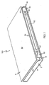
- Container 100 includes at least one latch 50 that holds lid 4 closed to base 2 when latch 50 is in the latched position shown in Figs. 1 and 2 .
- latch 50 is disposed adjacent the corner of the container.
- Hinge 52 is disposed perpendicular to living hinges 26 and 28 and is vertical when the container is disposed flat on bottom wall 12 (disposed perpendicular to the longitudinal direction of the front wall of container 100).
- Latch 50 may be disposed flush with or inwardly of the outermost portions of front walls 16 and 34.
- a pivot bar 102 extends outwardly from one of, or both, front walls 16 and 34 to allow an outer end potion 104 of latch 50 to be pivoted outwardly when the user pushes on latch 50 between bar 102 and hinge 52 as shown in Fig. 4 .
- This latch may be moved to a storage position inside the storage chamber of the container by opening lid 4, pivoting latch 50 inside container 100, and then closing lid 4.
- an opening for latch 50 is provided in front wall 34 of lid 4 near hinge 52 to allow lid 4 to close over latch 50.
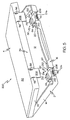
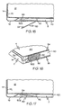
- Container 200 includes at least one latch 50 that holds lid 4 closed with respect to base 2 when latch 50 is in the latched position shown in Figs. 7 and 8 .
- latch 50 may be moved to a storage position where latch 50 is disposed inwardly of the outer periphery of the container as shown in Figs. 5 and 6 .
- the storage position of latch 50 may be completely within the storage chamber 202 of the container or may cross one of front walls 16 and 34 to be partially disposed within chamber 202.
- a bottom opening 204 allows latch 50 to be molded in the storage position as shown in Figs. 5 and 6 .
- latch 50 When latch 50 is needed, latch 50 may be pivoted out through a gap 206 defined by front wall 16 to an unlatched position. Lid 4 then may be closed causing a blocking wall 208 portion (that may define openings 56) of front wall 34 to fill a substantial portion of gap 206. In this position, wall 208 may engage latch 50. Latch 50 then may be moved to the latched position causing fingers 54 to snap into openings 56.
- Support walls 210 may extend inwardly on the sides of gap 206 to stiffen the container around latch 50 and to prevent latch 50 from catching on the inner surface of front wall 16 when latch 50 is pivoted from the storage position to the unlatched position.
- Latch 50 may define a finger detent 212 to allow the user to grasp latch 50 to pull it from the latched position to the unlatched position.
- a protrusion 214 may extend from blocking wall 208 to engage a recess defined by latch 50 to stiffen the container when lid 4 is closed and latch 50 is latched or unlatched.
- Another protrusion 216 may extend from latch 50 to engage a recess to stiffen the container when lid 4 is closed and latch 50 is latched or unlatched:
- Container may be closed for shipping without creating a container profile that is larger than a standard container.
- Retainers 18 and 20 may be used to keep lid 4 closed to base 2.
- the containers are shipped to a replicator where the container may be run through standard automation processes that place the item of recorded media in the container. Once the item of recorded media is loaded into container, latch 50 is moved to the unlatched position, the lid is closed, and the latch is moved to the latched position.
- the loaded container then may be wrapped and delivered to a retail facility.
- the customer purchases the container the customer moves latch 50 from the latched position to the unlatched position, opens lid 4, and pivots latch 50 back to its storage position.
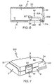
- Container 500 includes at least one outer latch 50 that holds lid 4 closed to base 2 when latch 50 is in the latched position shown in Figs. 16 and 17 .
- This configuration allows latch 50 to be disposed in a storage position that is inside the outer periphery of the container but not within the storage chamber of the container because latch 50 remains disposed outwardly of front walls 16 and 34 as shown in Figs 14 and 15 .
- a detent 502 holds latch 50 in the storage position.
Abstract
Description
- The present invention generally relates to media storage containers and, more particularly, to media storage containers having latches that are used to keep the lid and base together in the closed position until the latch is moved to an unlatched position.
- A variety of latches have been used with media storage containers to hold the container lid closed with respect to the container base. Drawbacks with existing containers include the need to close the latches when the containers are shipped. Closed latches must be unlatched before the containers are loaded with media. When latches are left opened for shipment, extra room must be provided in the shipping containers. Another drawback is that consumers must tear some latches from the containers once the containers have been purchased. If the consumer wishes to retain the latches and use them from time to time, the latches are otherwise hanging outwardly from the container when not being used. A media storage container having a latch that may be moved to a storage position is thus desired in the media packaging art.
-
US 2003/075463 A1 reflecting the preamble of claim 1,US 2003/146119 A1 andUS-A-5931291 describe media storage containers in which a hinged latch is movable from a latched position in which a lid cannot be opened to an unlatched position in which it can. - The invention provides a media storage container according to claim 1, a method of packaging recorded media according to
claim 12 and a method of opening a container according to claim 13. - The different elements of the exemplary configurations described herein may be used alone or in combination with each other to form additional configurations.
-
-
Fig. 1 is a perspective view of the front of a first configuration of a media storage container having an external latch. -
Fig. 2 is a top view of the latch ofFig. 1 with the top wall of the lid removed to show the latch. -
Fig. 3 is a view similar toFig. 1 showing a force applied to the latch to move the latch to the unlatched position. -
Fig. 4 is a top view of the latch ofFig. 3 with the top wall of the lid removed to show the latch. -
Fig. 5 is a perspective view of the front of a second configuration of a media storage container having an external latch showing the latch in an internal position. -
Fig. 6 is a section view showing the latch disposed internal to the container. -
Fig. 7 is a perspective view similar toFig. 5 showing the latch in the latched position. -
Fig. 8 is a section view of the latch ofFig. 7 . -
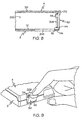
Fig. 9 is a perspective view showing a user moving the latch from the latched position to the unlatched position. -
Fig. 14 is a perspective view of the front of a third configuration of a media storage container having an external latch showing the latch in an unlatched position. -
Fig. 15 is a section view of the latch ofFig. 14 . -
Fig. 16 is a view similar toFig. 14 showing the latch in its latched position. -
Fig. 17 is a section view of the latch ofFig. 16 . -
Fig. 22 is a schematic view of an open container having features common to the configurations of the application. - The features of these configurations may be used alone or in combination with each other.
- Common reference numerals are used in the following descriptions of the different configurations of the media storage container for similar parts of the containers.
Fig. 22 depicts the common container features. In general, the following container configurations have abase 2 and alid 4. The lid and base may also be referred to as a container portions. These portions are movable relative to one another between open and closed positions. The open position provides access to the item stored within the container while the closed position inhibits such access. When the portions are closed, the container has an outer periphery that is defined as the outer boundaries of the container. This outer boundary - and thus the outer periphery - extends across openings and indentations defined by a container surface. The outer boundaries are the outermost surfaces of the container portions. Although the portions are typically hinged together to form a clamshell arrangement, some containers utilize a sliding configuration while others allow the portions to become completely separated when in the open position. - One, or both, of
base 2 andlid 4 includes a media retainer 6 adapted to retain an item of recorded media. Retainer 6 may be a hub such as those known in the art for holding CDs and DVDs. The hub may be a push button-type hub or a fixed position hub. Retainer 6 also may be a disc retainer or cartridge retainer that holds the outer edges of a media cartridge. Retainer 6 also may be a pocket that allows at least a portion of the item of recorded media to be slipped into the pocket.Base 2 andlid 4 may further include a second retainer 6 that may or may not be different than the first retainer 6. One ofbase 2 andlid 4 may also include literature booklet retainers 8. When retainer 6 is configured to hold a media disc (such as a CD or a DVD), anest wall 10 may be disposed around retainer 6. -
Base 2 generally includes abottom wall 12 sized to cover the item of recorded media to be held by the media storage container. A peripheral wall including sidewalls and a front wall projects upwardly from the outer peripheral edge or near the outer peripheral edge ofbottom wall 12.Sidewalls 14 project upwardly from opposite lateral edges ofbottom wall 12.Sidewalls 14 are generally disposed perpendicular tobottom wall 12.Base 2 also includes afront wall 16 that generally extends perpendicular tosidewalls 14 and tobottom wall 12.Front wall 16 may be integrally connected tosidewalls 14 at the corners ofbase 2. In containers havingbottom walls 12 that end atsidewalls 14 andfront wall 16, the outermost surfaces ofsidewalls 14 andfront wall 16 define a portion of the outer periphery of the container. Whenbottom wall 12 extends beyond the outer surface offront wall 16 to form a ledge, the outer periphery of the container is defined by the outermost edge ofbottom wall 12. - Inner lid retainers 18 are typically disposed
adjacent front wall 16 forholding lid 4 closed as is know in the art. Retainers 18 also may be positionedadjacent sidewalls 14 or inwardly from eithersidewalls 14 orfront wall 16. Retainers 18 frictionally hold or hold with a snap-fit afoot portion 20 oflid 4 to preventlid 4 from undesirably swinging open.Foot portions 20 may be enlarged to snap fit into retainers 18. Retainers 18 may be disposed onlid 4 withfoot portions 20 being disposed onbase 2. -
Base 2 may also include ahinge wall 24 that is connected tobottom wall 12 with afirst hinge 26 such as a living hinge.Hinge wall 24 may be connected tolid 4 with asecond hinge 28 such as asecond living hinge 28 spaced from and disposed parallel to thefirst living hinge 26.Second living hinge 28 may be connected to atop wall 30 oflid 4. The outermost surface ofhinge wall 24 defines a portion of the outer periphery of the container whenbase 2 andlid 4 do not extend beyondhinge wall 24. -
Sidewalls 32 project outwardly from opposite lateral edges oftop wall 30.Sidewalls 32 are disposed perpendicular totop wall 30.Lid 4 also includes afront wall 34 that is perpendicular to sidewalls 32 and totop wall 30.Front wall 34 is integrally connected to sidewalls 32 at the corners oflid 4. In containers havingtop walls 20 that end at sidewalls 32 andfront wall 34, the outermost surfaces ofsidewalls 32 andfront wall 34 define a portion of the outer periphery of the container.Front walls central portion 40 the surfaces that defineinset 40 is not a portion of the outer periphery of the container. - Each of the following configurations includes a
latch 50 that is movable between an unlatched position (allowinglid 4 to be opened and closed with respect to base 2) to a latched position (whereinlid 4 is held in its closed position). In a first embodiment of each configuration, latch 50 may be moved from the latched position to the unlatched position without the need for a specially designed key. Eachlatch 50 is connected to one ofbase 2 andlid 4. In the exemplary configurations, latches 50 are connected tobases 2.Latches 50 also may be connected tolids 4 with the appropriate elements reversed on container. Unless otherwise specified, the invention functions in a similar manner regardless to which container portion (base or lid)latch 50 is connected. In the exemplary embodiments, eachlatch 50 is connected to the container with ahinge 52 that allowslatch 50 to pivot abouthinge 52 between the unlatched and latched positions.Latch 50 and hinge 52 may be configured to placelatch 50 inside the outer periphery of the container, flush with the outer periphery of the container, or outside the outer periphery of the container.Hinge 52 optionally may be configured to allow the user to easily tearlatch 50 away from container without undue effort or cutting tools. Eachlatch 50 includes at least one latchingfinger 54 that engages the container to holdlatch 50 in the latched position. Latchingfinger 54 may be disposed through anopening 56 or may engage aledge 56 to engage the container with a snap fit. - The first configuration of the media storage container is indicated generally by the numeral 100 in
Figs 1-4 .Container 100 includes at least onelatch 50 that holdslid 4 closed tobase 2 whenlatch 50 is in the latched position shown inFigs. 1 and2 . Incontainer 100,latch 50 is disposed adjacent the corner of the container.Hinge 52 is disposed perpendicular to living hinges 26 and 28 and is vertical when the container is disposed flat on bottom wall 12 (disposed perpendicular to the longitudinal direction of the front wall of container 100).Latch 50 may be disposed flush with or inwardly of the outermost portions offront walls latch 50, apivot bar 102 extends outwardly from one of, or both,front walls outer end potion 104 oflatch 50 to be pivoted outwardly when the user pushes onlatch 50 betweenbar 102 and hinge 52 as shown inFig. 4 . This latch may be moved to a storage position inside the storage chamber of the container by openinglid 4, pivotinglatch 50 insidecontainer 100, and then closinglid 4. When a storage position forlatch 50 is desired, an opening forlatch 50 is provided infront wall 34 oflid 4 nearhinge 52 to allowlid 4 to close overlatch 50. - The second configuration of the media storage container is indicated generally by the numeral 200 in
Figs. 5-9 .Container 200 includes at least onelatch 50 that holdslid 4 closed with respect tobase 2 whenlatch 50 is in the latched position shown inFigs. 7 and8 . Incontainer 200, latch 50 may be moved to a storage position wherelatch 50 is disposed inwardly of the outer periphery of the container as shown inFigs. 5 and6 . The storage position oflatch 50 may be completely within thestorage chamber 202 of the container or may cross one offront walls chamber 202. - A
bottom opening 204 allowslatch 50 to be molded in the storage position as shown inFigs. 5 and6 . Whenlatch 50 is needed, latch 50 may be pivoted out through agap 206 defined byfront wall 16 to an unlatched position.Lid 4 then may be closed causing a blockingwall 208 portion (that may define openings 56) offront wall 34 to fill a substantial portion ofgap 206. In this position,wall 208 may engagelatch 50.Latch 50 then may be moved to the latchedposition causing fingers 54 to snap intoopenings 56.Support walls 210 may extend inwardly on the sides ofgap 206 to stiffen the container aroundlatch 50 and to preventlatch 50 from catching on the inner surface offront wall 16 whenlatch 50 is pivoted from the storage position to the unlatched position.Latch 50 may define afinger detent 212 to allow the user to grasplatch 50 to pull it from the latched position to the unlatched position. Aprotrusion 214 may extend from blockingwall 208 to engage a recess defined bylatch 50 to stiffen the container whenlid 4 is closed andlatch 50 is latched or unlatched. Anotherprotrusion 216 may extend fromlatch 50 to engage a recess to stiffen the container whenlid 4 is closed andlatch 50 is latched or unlatched: - This configuration of the container allows
latch 50 to be molded in the storage position if desired. Container may be closed for shipping without creating a container profile that is larger than a standard container.Retainers 18 and 20 may be used to keeplid 4 closed tobase 2. The containers are shipped to a replicator where the container may be run through standard automation processes that place the item of recorded media in the container. Once the item of recorded media is loaded into container,latch 50 is moved to the unlatched position, the lid is closed, and the latch is moved to the latched position. The loaded container then may be wrapped and delivered to a retail facility. When the customer purchases the container, the customer moves latch 50 from the latched position to the unlatched position, openslid 4, and pivots latch 50 back to its storage position. The customer then may use the container just as a typical storage container would be used. In the alternative, the customer may removelatch 50 by tearinghinge 52. Another alternative is to movelatch 50 from the storage position to the unlatched position before the container is run through the automated media loading process.Lid 50 may be closed automatically and latches 50 may be latched automatically by the automated equipment. - The third configuration of the media storage container is indicated generally by the numeral 500 in
Figs. 14-17 .Container 500 includes at least oneouter latch 50 that holdslid 4 closed tobase 2 whenlatch 50 is in the latched position shown inFigs. 16 and 17 . This configuration allowslatch 50 to be disposed in a storage position that is inside the outer periphery of the container but not within the storage chamber of the container becauselatch 50 remains disposed outwardly offront walls Figs 14 and15 . Adetent 502 holdslatch 50 in the storage position. - The concepts of the different configurations may be interchanged with each other to provide further container configurations.
Claims (13)
- A media storage container (100, 200, 500) comprising:a base (2);a lid (4) associated with the base (2) and movable with respect to the base (2) between open and closed positions;a latch (50) connected to one of the base (2) and lid (4) with a hinge (52); the latch being movable between unlatched and latched positions;in the latched position, the latch (50) engaging the other of the base (2) and lid (4) to prevent the lid from being moved from the closed position to the open position;in the unlatched position, the latch (50) allowing the lid (4) to be moved from the closed position to the open position;characterised in thatthe latch (50) is also movable to a storage position;in the storage position, the latch (50) being disposed inwardly of the outer periphery of the base (2) and lid (4) when the lid is closed and the latch (50) allowing the lid to be moved from the closed position to the open position.
- The container of claim 1, wherein the base (2) and lid (4) have front walls; the latch (50) being disposed outwardly of the outer periphery of the base (2) and lid (4) front walls (16, 34) when the lid (4) is closed and the latch (50) is in the unlatched position.
- The container of claim 2, wherein the latch (50) pivots between the latched, unlatched, and storage positions.
- The container of claim 1, wherein the base (2) includes a hinge wall (24) and a bottom wall (12); the hinge wall (24) being connected to the bottom wall (12) with a first living hinge (26), and the hinge wall is connected to the lid (4) with a second living hinge (28); and the first and second living hinges (26, 28) being parallel and spaced apart.
- The container of claim 1, further comprising a retainer (502) that holds the latch in the storage position.
- The container of claim 1, wherein the other of the base (2) and lid (4) has a front wall (16, 34) that defines a latch opening (56); the latch (50) including a finger (54) disposed in the latch opening (56) when the lid (4) is closed and the latch (50) is in the latched position.
- The container of claim 1, wherein the one of the base (2) and lid (4) to which the latch (50) is connected has a front wall (16, 34); the front wall (16, 34) defining a gap (206) that allows the latch (50) to pivot through the gap (206) from the unlatched position to the storage position.
- The container of claim 1, wherein the latch (50) may be removed from the container by tearing the latch (50) from the container (100, 200, 500).
- The container of claim 1, further comprising an inner retainer (18, 20) releasably holding the lid in the closed configuration; the inner retainer (18, 20) being disposed inwardly of the front walls (16, 34) of the base (2) and lid (4) when the lid is in the closed position.
- The container of claim 7, wherein the lid (4) includes a blocking wall (208) that is aligned with that gap (206) defined by the front wall (16) of the base (2) when the lid (4) is in the closed position.
- The container of claim 10, wherein the blocking wall (208) fills a substantial portion of the gap (206) defined by the front wall (16) of the base (2) when the lid (4) is in the closed position.
- A method of packaging recorded media using a media storage container; the method comprising the steps of:(A) providing a media storage container (100, 200, 500) having a base (2), a lid (4), and a latch (50); the latch movable between unlatched, latched, and storage positions;(B) moving the latch (50) to the storage position;(C) closing the lid (4) to form a closed container;(D) shipping the closed container to a replicator;(E) opening the lid (4);(F) loading an item of recorded media into the container;(G) moving the latch (50) to the unlatched position;(H) closing the lid (4); and(I) moving the latch (50) to the latched position.
- A method of opening a media storage container (100, 200, 500) having an externally accessible latch (50) that holds the lid (4) closed when the latch (50) is in a latched position; the method comprising the steps of:moving the latch (50) to an unlatched position;opening the media storage container;moving the latch (50) to a storage position inside the media storage container; andclosing the media storage container over a portion of the latch (50).
Priority Applications (1)
| Application Number | Priority Date | Filing Date | Title |
|---|---|---|---|
| PL06838747T PL1955331T3 (en) | 2005-12-02 | 2006-11-30 | Media storage container |
Applications Claiming Priority (2)
| Application Number | Priority Date | Filing Date | Title |
|---|---|---|---|
| US74170805P | 2005-12-02 | 2005-12-02 | |
| PCT/US2006/045945 WO2007064852A1 (en) | 2005-12-02 | 2006-11-30 | Media storage container |
Publications (2)
| Publication Number | Publication Date |
|---|---|
| EP1955331A1 EP1955331A1 (en) | 2008-08-13 |
| EP1955331B1 true EP1955331B1 (en) | 2011-04-27 |
Family
ID=37906891
Family Applications (2)
| Application Number | Title | Priority Date | Filing Date |
|---|---|---|---|
| EP06838747A Not-in-force EP1955331B1 (en) | 2005-12-02 | 2006-11-30 | Media storage container |
| EP06844726A Not-in-force EP1973810B1 (en) | 2005-12-02 | 2006-12-01 | Media storage container with storable latch |
Family Applications After (1)
| Application Number | Title | Priority Date | Filing Date |
|---|---|---|---|
| EP06844726A Not-in-force EP1973810B1 (en) | 2005-12-02 | 2006-12-01 | Media storage container with storable latch |
Country Status (7)
| Country | Link |
|---|---|
| US (2) | US7918357B2 (en) |
| EP (2) | EP1955331B1 (en) |
| CN (2) | CN101292297B (en) |
| AT (2) | ATE507562T1 (en) |
| DE (2) | DE602006021609D1 (en) |
| PL (1) | PL1955331T3 (en) |
| WO (2) | WO2007064852A1 (en) |
Families Citing this family (20)
| Publication number | Priority date | Publication date | Assignee | Title |
|---|---|---|---|---|
| US7918357B2 (en) * | 2005-12-02 | 2011-04-05 | Atlas Agi Holdings Llc | Media storage container |
| US7721883B2 (en) * | 2006-07-10 | 2010-05-25 | Finest Products Limited | Disk protective enclosure |
| US7721882B2 (en) * | 2006-08-18 | 2010-05-25 | Finest Products Limited | Disk protective enclosure |
| US20080041742A1 (en) * | 2006-08-18 | 2008-02-21 | Finest Products Limited | Security Disk Protective Enclosure |
| FR2920246A1 (en) * | 2007-08-20 | 2009-02-27 | Frederic Itey | DVD BOX |
| US7975844B2 (en) * | 2008-02-20 | 2011-07-12 | Encore Holdings Ltd | Optical media disc case |
| US8649167B2 (en) * | 2009-06-19 | 2014-02-11 | Hewlett-Packard Development Company, L.P. | Pivoting mounts for media drives |
| CN102759960A (en) * | 2011-04-27 | 2012-10-31 | 鸿富锦精密工业(深圳)有限公司 | Hard disk fixing device |
| US20130180208A1 (en) * | 2012-01-18 | 2013-07-18 | International Microsystems, Inc. (Imi) | Apparatus for loading containers with objects |
| US9247656B2 (en) | 2013-08-30 | 2016-01-26 | Western Digital Technologies, Inc. | Latch system |
| USD766624S1 (en) | 2014-03-13 | 2016-09-20 | Finest Products Limited | Case |
| WO2017022068A1 (en) * | 2015-08-04 | 2017-02-09 | 三菱電機株式会社 | Assembly structure for housing of electronic device, and electronic device |
| US10538365B2 (en) * | 2018-01-16 | 2020-01-21 | Cascade Mountain Technologies, Llc | Insulating device and latch |
| US11136173B2 (en) | 2018-05-11 | 2021-10-05 | Sto Responsible, LLC | Child-resistant storage container |
| WO2019220684A1 (en) * | 2018-05-16 | 2019-11-21 | 株式会社島津製作所 | Device reception structure for fluid chromatography |
| USD941523S1 (en) | 2018-08-22 | 2022-01-18 | Sto Responsible, LLC | Child-resistant storage container |
| CA3080678A1 (en) * | 2019-06-27 | 2020-12-27 | Dongguan Lk Tin Packaging Co.,Ltd. | Container with security lock |
| CA3051959A1 (en) * | 2019-06-27 | 2020-12-27 | Dongguan Lk Tin Packaging Co.,Ltd. | Container with security lock |
| CA3226088A1 (en) * | 2021-07-16 | 2023-01-19 | Samir R. Parikh | Reclosable plastic container with readily apparent tamper evident feature |
| US11738914B2 (en) | 2021-11-18 | 2023-08-29 | Yeti Coolers, Llc | Container and latching system |
Family Cites Families (149)
| Publication number | Priority date | Publication date | Assignee | Title |
|---|---|---|---|---|
| US976165A (en) | 1910-02-24 | 1910-11-22 | Norman D Gray | Puzzle-lock. |
| US1774543A (en) * | 1929-06-01 | 1930-09-02 | John V Pilcher | Vanity case |
| US2411946A (en) | 1944-07-28 | 1946-12-03 | Vogel Max | Container for cigarette packages or the like |
| US3108734A (en) * | 1961-03-28 | 1963-10-29 | Hewko Roman | Stamp collection register |
| US3175853A (en) * | 1962-04-30 | 1965-03-30 | John E Gilbertson | Lock means |
| FR1396369A (en) * | 1964-02-11 | 1965-04-23 | Allard & Fils | System for assembling, blocking and closing all or part of a cardboard or similar packaging |
| US3414157A (en) | 1965-06-23 | 1968-12-03 | Thomas E. Wright | Combined litter container and tissue dispenser |
| US3485408A (en) | 1968-04-03 | 1969-12-23 | Frederick E Benesch | Multi-sectioned container |
| US3494458A (en) * | 1968-04-23 | 1970-02-10 | American Home Prod | Tamperproof closure means for pilferproof package |
| US3608333A (en) * | 1968-06-20 | 1971-09-28 | Bison Mfg Co Inc | Vacuum cleaner and power unit |
| US3583556A (en) * | 1969-02-05 | 1971-06-08 | Theodore R Wagner | Tool carrier case |
| US3635331A (en) * | 1969-09-18 | 1972-01-18 | Armand S Zucker | Display packages |
| US3907103A (en) * | 1973-07-16 | 1975-09-23 | Howard G Shaw | Safety container |
| US3876071A (en) * | 1974-04-22 | 1975-04-08 | Amaray Int Corp | Storage container for tape cassette with self-locking spring to prevent tape spillage |
| US3933381A (en) * | 1974-11-04 | 1976-01-20 | The Plastic Forming Company, Inc. | Plastic container and latch |
| JPS56463Y2 (en) * | 1974-12-25 | 1981-01-08 | ||
| US3990575A (en) | 1975-12-10 | 1976-11-09 | Memorex Corporation | Cassette container lock mechanism |
| US4011940A (en) * | 1975-12-12 | 1977-03-15 | Amaray International Corporation | Hinged storage container for tape cartridge with self-aligning walls |
| JPS5928543Y2 (en) | 1976-02-13 | 1984-08-17 | ソニー株式会社 | cassette case |
| US4105112A (en) * | 1977-02-10 | 1978-08-08 | Howmedica Inc. | Lockable shipping box |
| US4078657A (en) * | 1977-02-22 | 1978-03-14 | Plastic Forming Company, Inc. | Tape cassette case |
| US4231474A (en) | 1978-04-07 | 1980-11-04 | Sony Corporation | Storage case |
| US4153178A (en) * | 1978-04-14 | 1979-05-08 | Minnesota Mining And Manufacturing Company | Double-acting latch for hinged plastic box |
| US4293266A (en) | 1978-09-08 | 1981-10-06 | Sensormatic Electronics Corporation | Anti-theft security enclosure and releasing mechanism |
| US4365711A (en) | 1979-01-05 | 1982-12-28 | Long Jerry M | Video cassette storage and shipping container apparatus |
| US4248345A (en) * | 1979-05-24 | 1981-02-03 | Bowers Robert C | Protective cap for a magnetic recording tape cassette |
| US4344646A (en) * | 1980-05-27 | 1982-08-17 | Woodstream Corporation | Detachable latch |
| US4291801A (en) * | 1980-10-03 | 1981-09-29 | Plastic Reel Corporation Of America | Video cassette storage container |
| US4381836A (en) * | 1981-06-15 | 1983-05-03 | Liberty Diversified Industries (Shamrock) | Anti-theft point-of-sale container |
| US4489832A (en) | 1983-07-08 | 1984-12-25 | Container Corporation Of America | Tamper-evident container |
| NL8303077A (en) * | 1983-09-05 | 1985-04-01 | Philips Nv | STORAGE BOX FOR A MAGNETIC CASSETTE. |
| US4531670A (en) * | 1984-06-18 | 1985-07-30 | Kupersmit Julius B | Combination clip and seal construction for shipping containers |
| US4610371A (en) * | 1984-10-09 | 1986-09-09 | Dougherty Brothers Company | Tamper evident dispensing closure assembly |
| US4634004A (en) * | 1984-12-11 | 1987-01-06 | Empak Inc. | Magnetic tape security housing |
| SE451906B (en) | 1986-02-13 | 1987-11-02 | Intermodulation & Safety Syste | ALARM DEVICE CONTAINING ONE OF THE TWO PARTS ALARM CONNECTOR WHICH IN AN ACTIVE EMERGENCY GIVES AN ACOUSTIC SIGNAL AS THE PARTS MOVE OUT OF EACH OTHER |
| US4643281A (en) * | 1986-02-18 | 1987-02-17 | Erickson Kenneth E | Carrying case |
| US4746008A (en) * | 1987-07-01 | 1988-05-24 | Heverly Karen H | Child-resistant box for storage of hazardous materials |
| GB2210026B (en) * | 1987-09-24 | 1991-12-18 | Kunimune Kogyosho Co Ltd | Case for compact disks |
| US4838420A (en) * | 1987-09-24 | 1989-06-13 | Bonneville International Corporation | Packaging for point of sale display, shipment and storage of cassette recordings and methods |
| US4834238A (en) * | 1987-11-06 | 1989-05-30 | Alpha Enterprises, Inc. | Cassette security package |
| FR2627458B1 (en) * | 1988-02-24 | 1990-07-20 | Oreal | ENCLOSURES, COMPRISING A BASE AND A LID CONNECTED TO EACH OTHER BY A JOINT PROVIDED WITH A CLOSURE DEVICE COMPRISING AT LEAST ONE MOBILE ELEMENT COOPERATING WITH FIXED ELEMENTS OF THE LID AND THE HOUSING |
| US4805769A (en) * | 1988-03-28 | 1989-02-21 | Liberty Diversified Industries | Compact disc security holder |
| US4871065A (en) | 1988-08-19 | 1989-10-03 | Alpha Enterprises, Inc. | Compact disc security package |
| US4865190A (en) * | 1988-10-27 | 1989-09-12 | Empak, Inc. | Security package with rotatable locking channel |
| SE463762B (en) * | 1989-05-31 | 1991-01-21 | Akerlund & Rausing Licens Ab | AEROUS CLOSING LOCK WITH OVERWEIGHT CLAFING PROTECTOR |
| US4921097A (en) * | 1989-08-01 | 1990-05-01 | Specialty Store Services, Inc. | Display case for a jacketed cassette |
| US4974740A (en) | 1990-03-05 | 1990-12-04 | Minnesota Mining And Manufacturing Company | Triple-action latch for a shipping case |
| US5033778A (en) * | 1990-04-16 | 1991-07-23 | Minnesota Mining And Manufacturing Company | Integral over-center toggle latch for use with a molded case |
| ES2040013T3 (en) * | 1990-09-26 | 1993-10-01 | Firma Georg Knoblauch | CASE WITH FLAT PACKAGE FOR THE STORAGE OF LONG OBJECTS. |
| US5562207A (en) | 1991-05-10 | 1996-10-08 | Ivy Hill Corporation | Short end cap storage package |
| US5211823A (en) * | 1991-06-19 | 1993-05-18 | Millipore Corporation | Process for purifying resins utilizing bipolar interface |
| US5211283A (en) | 1992-01-27 | 1993-05-18 | Alpha Enterprises, Inc. | Compact disc security package with orienting tabs |
| US5215188A (en) * | 1992-02-24 | 1993-06-01 | Empak, Inc. | Security package with a slidable locking mechanism |
| US5259221A (en) | 1992-03-06 | 1993-11-09 | Long Manufacturing Company, Inc. | Trunk lock with manual release |
| US5346069A (en) | 1992-09-24 | 1994-09-13 | Intini Thomas D | Container |
| US5285918A (en) * | 1992-12-10 | 1994-02-15 | Alpha Enterprises, Inc. | Videocassette shipping container |
| US5305873A (en) * | 1993-01-12 | 1994-04-26 | Joyce Molding | Package for recording media |
| US5297672A (en) * | 1993-01-27 | 1994-03-29 | Mactavish William D | Security package for compact discs |
| JP3416994B2 (en) * | 1993-08-20 | 2003-06-16 | ソニー株式会社 | Tape cassette storage case |
| US5417319A (en) * | 1994-03-22 | 1995-05-23 | Hydrabaths, Inc. | Security container for display of audio and video media |
| US5662218A (en) * | 1994-04-05 | 1997-09-02 | Agi Incorporated | Reusable compact disc package |
| US5551560A (en) * | 1994-06-30 | 1996-09-03 | Alpha Enterprises, Inc. | Container for compact disc and jewel box |
| US5460266A (en) | 1994-07-15 | 1995-10-24 | Alpha Enterprises, Inc. | Security package |
| DE69513798T2 (en) * | 1994-09-27 | 2000-06-08 | Citizen Watch Co Ltd | STORAGE AND SECURITY DEVICE FOR AN OBJECT |
| US5515967A (en) * | 1994-10-31 | 1996-05-14 | Fitzsimmons; W. Tyler | CD-Rom retailer |
| GB2291640B (en) * | 1994-11-03 | 1996-07-24 | Dubois Plc | Apparatus for holding a compact disk |
| US5443159A (en) * | 1994-11-07 | 1995-08-22 | Cheng; Yu-Feng | Tri-cassette carrier |
| US5509528A (en) * | 1994-11-16 | 1996-04-23 | Alpha Enterprises, Inc. | Display package |
| ATE152987T1 (en) * | 1995-01-26 | 1997-05-15 | Tapematic Spa | METHOD AND DEVICE FOR PACKAGING COMPACT DISCS IN CD BOXES |
| US5566828A (en) | 1995-02-21 | 1996-10-22 | The Upjohn Company | Locking package for a syringe |
| US5799782A (en) * | 1995-04-10 | 1998-09-01 | Gelardi; John A. | Compact disc case |
| AUPN239695A0 (en) * | 1995-04-13 | 1995-05-11 | Mcewan, Sturt | Compact disc cassette case |
| DE59506475D1 (en) | 1995-05-10 | 1999-09-02 | Thulin Cartonneries | Cassette for holding at least one disc with information stored or to be stored on it with high character density (compact disc) |
| US5730283A (en) * | 1995-07-03 | 1998-03-24 | Autronic Plastics, Inc. | Package and storage unit for digital information storage media |
| US5988376A (en) | 1995-07-03 | 1999-11-23 | Autronics Plastics, Inc. | Security devices for information storage media with locking mechanisms |
| US5597068A (en) * | 1995-08-25 | 1997-01-28 | Alpha Enterprises, Inc. | Compact disc security container |
| EP0771736A1 (en) * | 1995-10-30 | 1997-05-07 | Plastofilm Industries, Inc. | Tamper evident thermoformed package |
| JP2741361B2 (en) | 1995-11-10 | 1998-04-15 | 株式会社サンエイ | Videotape storage case |
| US5680932A (en) | 1995-12-15 | 1997-10-28 | Contico International, Inc. | Toolbox assembly |
| HU947U (en) * | 1996-02-23 | 1996-11-28 | Westline Kft | Safety box |
| JP3278343B2 (en) * | 1996-02-23 | 2002-04-30 | 富士写真フイルム株式会社 | Disk cartridge storage case |
| JP3256437B2 (en) * | 1996-06-06 | 2002-02-12 | 株式会社ハゴロモ | Storage container such as CD |
| US5636737A (en) * | 1996-07-26 | 1997-06-10 | Alpha Enterprises, Inc. | Video cassette shipping container |
| JP3158272B2 (en) * | 1996-08-09 | 2001-04-23 | 株式会社サンエイ | Soft storage case holder |
| US5645167A (en) * | 1996-08-30 | 1997-07-08 | Conrad; Keith | Paint brush container |
| US5697498A (en) | 1996-09-09 | 1997-12-16 | Fellowes Mfg. Co. | Carrying case for recorded media |
| WO1998017549A1 (en) | 1996-10-21 | 1998-04-30 | Weingarden Marshall L | Storage container for information bearing disc devices |
| IT1298682B1 (en) | 1997-02-14 | 2000-01-12 | Pietro Necchi | ANTI-THEFT CASE WITH SMALL SPACE, IN PARTICULAR FOR COMPACT DISK, MUSIC CASSETTE, VIDEO CASSETTE AND SIMILAR |
| US5782350A (en) * | 1997-02-19 | 1998-07-21 | Alpha Enterprises, Inc. | Magnetic locking mechanism for a security package |
| US5904246A (en) * | 1997-02-19 | 1999-05-18 | Alpha Enterprises, Inc. | Magnetic locking mechanism for a security package |
| US5934114A (en) * | 1997-02-19 | 1999-08-10 | Alpha Enterprises, Inc. | Mechanical locking mechanism for a security package |
| US5727681A (en) * | 1997-02-27 | 1998-03-17 | Li; Ching-Hsiang | Compact disk arrangement case structure |
| US6105767A (en) * | 1997-04-11 | 2000-08-22 | Maxtech, Inc. | Tool case with butterfly door |
| US5878878A (en) * | 1997-05-07 | 1999-03-09 | Wu; Hsien-Chang | Case structure with two openable sides |
| US5819929A (en) | 1997-07-21 | 1998-10-13 | Chung; Chih-Wen | CD container storage device |
| US5762187A (en) * | 1997-08-05 | 1998-06-09 | Alpha Enterprises, Inc. | Security container |
| US5931291A (en) * | 1997-08-08 | 1999-08-03 | Alpha Enterprises, Inc. | Multi-media shipping and storage container |
| KR100269853B1 (en) * | 1997-10-16 | 2000-10-16 | 임옥빈 | Compact disk case with thief-protecting function |
| US5899327A (en) * | 1997-10-31 | 1999-05-04 | Ufe, Inc. | Protective storage case for digital discs, computer game cartridges and the like |
| ES1038807Y (en) * | 1997-11-20 | 1999-06-16 | Magnetic Imatge Sa | CASE OF COMPACT DISCS, DIGITAL VIDEO DISCS OR SIMILAR. |
| US5944185A (en) * | 1998-01-29 | 1999-08-31 | Alpha Enterprises, Inc. | Lockable media storage box with lock and key |
| US5996788A (en) | 1998-04-01 | 1999-12-07 | Alpha Enterprises, Inc. | Storage container for recorded media |
| US6196384B1 (en) * | 1998-04-01 | 2001-03-06 | Alpha Enterprises, Inc. | Storage container for recorded media |
| US5944173A (en) * | 1998-06-05 | 1999-08-31 | Emplast, Inc. | Security package for displaying merchandise in a retail store |
| US5944181A (en) * | 1998-09-09 | 1999-08-31 | Finest Industrial Co., Ltd. | Disk protective enclosure |
| US6119857A (en) * | 1998-11-25 | 2000-09-19 | Stumpff; David | Hinge |
| JP2000159284A (en) * | 1998-11-27 | 2000-06-13 | Fuji Photo Film Co Ltd | Storing case for magnetic tape cassette |
| CN2358525Y (en) * | 1998-12-07 | 2000-01-12 | 展成磁电有限公司 | Disk box |
| DK199801633A (en) | 1998-12-09 | 2000-06-10 | Scanavo A S | A storage device for a data carrier |
| US6070721A (en) * | 1999-01-11 | 2000-06-06 | Levitan; Richard J. | Display case for phonograph album and record |
| HK1029888A2 (en) | 2000-02-25 | 2001-03-30 | Media State Group Ltd | Data disc box |
| US5988375A (en) | 1999-03-26 | 1999-11-23 | Snyr Yih Metallic Co., Ltd. | Disc box structure |
| US6155417A (en) | 1999-03-26 | 2000-12-05 | Filam National Plastics | Disc storage container with retaining means |
| US6076667A (en) * | 1999-05-04 | 2000-06-20 | Ambrus; Sandor Z. | Safety device to prevent the unlawful appropriation of shop goods |
| US6070722A (en) * | 1999-05-19 | 2000-06-06 | Ng; Chan-Pao | Compact disc protective cartridge structure |
| AU4775000A (en) | 1999-05-31 | 2000-12-18 | Dualbox Limited | Apparatus for holding a disc-like article |
| US6102200A (en) * | 1999-09-03 | 2000-08-15 | Emplast, Inc. | Security package with asymmetric lock |
| US6237763B1 (en) * | 2000-05-11 | 2001-05-29 | Kwok Din Lau | Disk protection enclosure |
| US20020033348A1 (en) | 2000-05-18 | 2002-03-21 | Flores Victorio T. | Disc storage container |
| IES20010822A2 (en) | 2000-09-11 | 2002-04-17 | Dualbox Ltd | Improvements relating to a case for a disc-like article |
| US6398022B1 (en) * | 2000-11-07 | 2002-06-04 | Cheong Wing Electric, Ltd. | Digital video disk holder |
| CN2447910Y (en) * | 2000-11-07 | 2001-09-12 | 李清茂 | CD storage case |
| US20030173369A1 (en) * | 2000-12-07 | 2003-09-18 | Rexam Cosmetic Packaging, Inc. | Container system |
| US20020096517A1 (en) * | 2001-01-19 | 2002-07-25 | Gelardi John A. | Strong hold, weak release pivoting, lifting and sliding recessed fulcrum and lever latch |
| US6832686B2 (en) | 2001-03-20 | 2004-12-21 | Michael Patrick Donegan | Child resistant compact case |
| US20030000856A1 (en) * | 2001-06-27 | 2003-01-02 | Autronic Plastics, Inc. | Storage case |
| US6789692B2 (en) * | 2001-07-13 | 2004-09-14 | Louis M. Prezelin | Container latch valve |
| US6863175B2 (en) * | 2001-07-18 | 2005-03-08 | Meadwestvaco Corporation | Locking container |
| US6719133B2 (en) * | 2001-10-19 | 2004-04-13 | Panasonic Disc Manufacturing Corporation Of America | Security storage container |
| US6710133B2 (en) * | 2001-11-07 | 2004-03-23 | Collins & Aikman Products Co. | Recyclable vehicle interior articles and methods of making same |
| AU2002357076A1 (en) | 2001-12-05 | 2003-06-17 | Nexpak Corporation | Lockable media storage container |
| US6619079B2 (en) * | 2001-12-28 | 2003-09-16 | Chung Fai Cheung | Security device for media storage disk box |
| CN2525645Y (en) * | 2002-02-04 | 2002-12-11 | 李清茂 | Secrete optic disc storage box |
| US20050121950A1 (en) | 2002-05-28 | 2005-06-09 | John Hegarty | Apparatus for holding a disc-shaped article |
| US20040144662A1 (en) * | 2003-01-24 | 2004-07-29 | Bolognia David L. | Insertable hinged tray for a multiple disc storage container |
| WO2004088071A2 (en) | 2003-03-26 | 2004-10-14 | Autronic Plastics, Inc. | Benefit denial systems for securing an asset within a container and methods of use |
| US7108129B2 (en) | 2003-10-10 | 2006-09-19 | Enxnet, Inc. | Optical disk storage case with blocking tongue |
| CN1894143A (en) | 2003-10-16 | 2007-01-10 | 米德韦斯瓦科公司 | Lockable container and method of making |
| US20050160774A1 (en) | 2004-01-23 | 2005-07-28 | Marshall Weinstein | Multimedia security case system with slide lock and key |
| US20050269223A1 (en) | 2004-06-07 | 2005-12-08 | Infiniti Media, Inc. | Apparatus for holding a media storage disk |
| US20060032860A1 (en) * | 2004-08-13 | 2006-02-16 | Hase Gary M | Container with lid prop and/or lid latch |
| AU2005309565B2 (en) | 2004-11-23 | 2010-11-25 | Autronic Plastics, Inc. | Apparatus and method for processing items |
| US20070267305A1 (en) | 2005-03-11 | 2007-11-22 | Robert Johnston | Media container with band header |
| USD544743S1 (en) * | 2005-09-26 | 2007-06-19 | Autronic Plastics, Inc. | Media storage case |
| EP1949377A2 (en) | 2005-10-20 | 2008-07-30 | MeadWestvaco Corporation | Package with security features |
| US7549533B2 (en) | 2005-11-07 | 2009-06-23 | Encore Holdings Limited | Injection molded case for optical storage discs |
| US7416079B2 (en) | 2005-11-07 | 2008-08-26 | Encore Holdings Limited | Injection molded case for optical storage discs |
| US7428968B2 (en) | 2005-11-07 | 2008-09-30 | Encore Holdings Limited | Injection molded case for optical storage discs |
| US7918357B2 (en) * | 2005-12-02 | 2011-04-05 | Atlas Agi Holdings Llc | Media storage container |
-
2006
- 2006-11-30 US US11/606,773 patent/US7918357B2/en not_active Expired - Fee Related
- 2006-11-30 PL PL06838747T patent/PL1955331T3/en unknown
- 2006-11-30 DE DE602006021609T patent/DE602006021609D1/en active Active
- 2006-11-30 CN CN2006800387855A patent/CN101292297B/en not_active Expired - Fee Related
- 2006-11-30 AT AT06838747T patent/ATE507562T1/en active
- 2006-11-30 EP EP06838747A patent/EP1955331B1/en not_active Not-in-force
- 2006-11-30 WO PCT/US2006/045945 patent/WO2007064852A1/en active Application Filing
- 2006-12-01 CN CN2006800521290A patent/CN101400584B/en not_active Expired - Fee Related
- 2006-12-01 WO PCT/US2006/046064 patent/WO2007064925A1/en active Application Filing
- 2006-12-01 US US11/607,442 patent/US8079467B2/en not_active Expired - Fee Related
- 2006-12-01 DE DE602006016339T patent/DE602006016339D1/en active Active
- 2006-12-01 EP EP06844726A patent/EP1973810B1/en not_active Not-in-force
- 2006-12-01 AT AT06844726T patent/ATE478420T1/en not_active IP Right Cessation
Also Published As
| Publication number | Publication date |
|---|---|
| CN101400584A (en) | 2009-04-01 |
| CN101292297B (en) | 2012-05-30 |
| EP1973810A4 (en) | 2009-05-27 |
| WO2007064925A1 (en) | 2007-06-07 |
| EP1955331A1 (en) | 2008-08-13 |
| EP1973810A1 (en) | 2008-10-01 |
| DE602006021609D1 (en) | 2011-06-09 |
| CN101400584B (en) | 2010-11-10 |
| CN101292297A (en) | 2008-10-22 |
| US8079467B2 (en) | 2011-12-20 |
| EP1973810B1 (en) | 2010-08-18 |
| PL1955331T3 (en) | 2012-05-31 |
| ATE478420T1 (en) | 2010-09-15 |
| US7918357B2 (en) | 2011-04-05 |
| US20070138174A1 (en) | 2007-06-21 |
| WO2007064852A1 (en) | 2007-06-07 |
| DE602006016339D1 (en) | 2010-09-30 |
| US20070215498A1 (en) | 2007-09-20 |
| ATE507562T1 (en) | 2011-05-15 |
Similar Documents
| Publication | Publication Date | Title |
|---|---|---|
| EP1955331B1 (en) | Media storage container | |
| US7431154B2 (en) | Security storage container | |
| US20030196918A1 (en) | Security device for a disk box | |
| US6832498B2 (en) | Security storage container | |
| US5297672A (en) | Security package for compact discs | |
| US7526931B2 (en) | Security device for media case and method | |
| GB2137167A (en) | Containers having hinged lids | |
| JP2004533976A (en) | Media disc package with security lock for retail | |
| US6896132B1 (en) | Storage media case | |
| US6029812A (en) | Reinforced hinge for storage media package | |
| EP1999326B1 (en) | Universal retail security package with cover window | |
| JP4336832B2 (en) | CD container | |
| EP2255360B1 (en) | A container | |
| WO2006068508A1 (en) | Media storage disc case | |
| US20070235356A1 (en) | Optical media storage package | |
| JP5639000B2 (en) | Compact container | |
| US7908828B2 (en) | Storage case having a media retention device | |
| RU2319822C2 (en) | Lockable protective device | |
| US20030116454A1 (en) | Lockable storage container for recorded media | |
| JP2001192035A (en) | Packaging container | |
| JP2003020091A (en) | Totally openable housing case |
Legal Events
| Date | Code | Title | Description |
|---|---|---|---|
| PUAI | Public reference made under article 153(3) epc to a published international application that has entered the european phase |
Free format text: ORIGINAL CODE: 0009012 |
|
| 17P | Request for examination filed |
Effective date: 20080326 |
|
| AK | Designated contracting states |
Kind code of ref document: A1 Designated state(s): AT BE BG CH CY CZ DE DK EE ES FI FR GB GR HU IE IS IT LI LT LU LV MC NL PL PT RO SE SI SK TR |
|
| 17Q | First examination report despatched |
Effective date: 20090316 |
|
| GRAP | Despatch of communication of intention to grant a patent |
Free format text: ORIGINAL CODE: EPIDOSNIGR1 |
|
| RAP1 | Party data changed (applicant data changed or rights of an application transferred) |
Owner name: MEADWESTVACO CORPORATION |
|
| DAX | Request for extension of the european patent (deleted) | ||
| GRAS | Grant fee paid |
Free format text: ORIGINAL CODE: EPIDOSNIGR3 |
|
| GRAA | (expected) grant |
Free format text: ORIGINAL CODE: 0009210 |
|
| AK | Designated contracting states |
Kind code of ref document: B1 Designated state(s): AT BE BG CH CY CZ DE DK EE ES FI FR GB GR HU IE IS IT LI LT LU LV MC NL PL PT RO SE SI SK TR |
|
| REG | Reference to a national code |
Ref country code: GB Ref legal event code: FG4D |
|
| REG | Reference to a national code |
Ref country code: CH Ref legal event code: EP |
|
| REG | Reference to a national code |
Ref country code: IE Ref legal event code: FG4D |
|
| REF | Corresponds to: |
Ref document number: 602006021609 Country of ref document: DE Date of ref document: 20110609 Kind code of ref document: P |
|
| REG | Reference to a national code |
Ref country code: DE Ref legal event code: R096 Ref document number: 602006021609 Country of ref document: DE Effective date: 20110609 |
|
| REG | Reference to a national code |
Ref country code: NL Ref legal event code: VDEP Effective date: 20110427 |
|
| RAP2 | Party data changed (patent owner data changed or rights of a patent transferred) |
Owner name: ATLAS AGI HOLDINGS, LLC |
|
| LTIE | Lt: invalidation of european patent or patent extension |
Effective date: 20110427 |
|
| REG | Reference to a national code |
Ref country code: GB Ref legal event code: 732E Free format text: REGISTERED BETWEEN 20110908 AND 20110914 |
|
| PG25 | Lapsed in a contracting state [announced via postgrant information from national office to epo] |
Ref country code: LT Free format text: LAPSE BECAUSE OF FAILURE TO SUBMIT A TRANSLATION OF THE DESCRIPTION OR TO PAY THE FEE WITHIN THE PRESCRIBED TIME-LIMIT Effective date: 20110427 Ref country code: SE Free format text: LAPSE BECAUSE OF FAILURE TO SUBMIT A TRANSLATION OF THE DESCRIPTION OR TO PAY THE FEE WITHIN THE PRESCRIBED TIME-LIMIT Effective date: 20110427 Ref country code: PT Free format text: LAPSE BECAUSE OF FAILURE TO SUBMIT A TRANSLATION OF THE DESCRIPTION OR TO PAY THE FEE WITHIN THE PRESCRIBED TIME-LIMIT Effective date: 20110829 |
|
| PG25 | Lapsed in a contracting state [announced via postgrant information from national office to epo] |
Ref country code: IS Free format text: LAPSE BECAUSE OF FAILURE TO SUBMIT A TRANSLATION OF THE DESCRIPTION OR TO PAY THE FEE WITHIN THE PRESCRIBED TIME-LIMIT Effective date: 20110827 Ref country code: CY Free format text: LAPSE BECAUSE OF FAILURE TO SUBMIT A TRANSLATION OF THE DESCRIPTION OR TO PAY THE FEE WITHIN THE PRESCRIBED TIME-LIMIT Effective date: 20110427 Ref country code: ES Free format text: LAPSE BECAUSE OF FAILURE TO SUBMIT A TRANSLATION OF THE DESCRIPTION OR TO PAY THE FEE WITHIN THE PRESCRIBED TIME-LIMIT Effective date: 20110807 Ref country code: LV Free format text: LAPSE BECAUSE OF FAILURE TO SUBMIT A TRANSLATION OF THE DESCRIPTION OR TO PAY THE FEE WITHIN THE PRESCRIBED TIME-LIMIT Effective date: 20110427 Ref country code: BE Free format text: LAPSE BECAUSE OF FAILURE TO SUBMIT A TRANSLATION OF THE DESCRIPTION OR TO PAY THE FEE WITHIN THE PRESCRIBED TIME-LIMIT Effective date: 20110427 Ref country code: GR Free format text: LAPSE BECAUSE OF FAILURE TO SUBMIT A TRANSLATION OF THE DESCRIPTION OR TO PAY THE FEE WITHIN THE PRESCRIBED TIME-LIMIT Effective date: 20110728 Ref country code: FI Free format text: LAPSE BECAUSE OF FAILURE TO SUBMIT A TRANSLATION OF THE DESCRIPTION OR TO PAY THE FEE WITHIN THE PRESCRIBED TIME-LIMIT Effective date: 20110427 Ref country code: SI Free format text: LAPSE BECAUSE OF FAILURE TO SUBMIT A TRANSLATION OF THE DESCRIPTION OR TO PAY THE FEE WITHIN THE PRESCRIBED TIME-LIMIT Effective date: 20110427 |
|
| PG25 | Lapsed in a contracting state [announced via postgrant information from national office to epo] |
Ref country code: NL Free format text: LAPSE BECAUSE OF FAILURE TO SUBMIT A TRANSLATION OF THE DESCRIPTION OR TO PAY THE FEE WITHIN THE PRESCRIBED TIME-LIMIT Effective date: 20110427 |
|
| PG25 | Lapsed in a contracting state [announced via postgrant information from national office to epo] |
Ref country code: CZ Free format text: LAPSE BECAUSE OF FAILURE TO SUBMIT A TRANSLATION OF THE DESCRIPTION OR TO PAY THE FEE WITHIN THE PRESCRIBED TIME-LIMIT Effective date: 20110427 Ref country code: EE Free format text: LAPSE BECAUSE OF FAILURE TO SUBMIT A TRANSLATION OF THE DESCRIPTION OR TO PAY THE FEE WITHIN THE PRESCRIBED TIME-LIMIT Effective date: 20110427 |
|
| PG25 | Lapsed in a contracting state [announced via postgrant information from national office to epo] |
Ref country code: RO Free format text: LAPSE BECAUSE OF FAILURE TO SUBMIT A TRANSLATION OF THE DESCRIPTION OR TO PAY THE FEE WITHIN THE PRESCRIBED TIME-LIMIT Effective date: 20110427 Ref country code: SK Free format text: LAPSE BECAUSE OF FAILURE TO SUBMIT A TRANSLATION OF THE DESCRIPTION OR TO PAY THE FEE WITHIN THE PRESCRIBED TIME-LIMIT Effective date: 20110427 Ref country code: DK Free format text: LAPSE BECAUSE OF FAILURE TO SUBMIT A TRANSLATION OF THE DESCRIPTION OR TO PAY THE FEE WITHIN THE PRESCRIBED TIME-LIMIT Effective date: 20110427 |
|
| PLBE | No opposition filed within time limit |
Free format text: ORIGINAL CODE: 0009261 |
|
| STAA | Information on the status of an ep patent application or granted ep patent |
Free format text: STATUS: NO OPPOSITION FILED WITHIN TIME LIMIT |
|
| 26N | No opposition filed |
Effective date: 20120130 |
|
| REG | Reference to a national code |
Ref country code: DE Ref legal event code: R097 Ref document number: 602006021609 Country of ref document: DE Effective date: 20120130 |
|
| PG25 | Lapsed in a contracting state [announced via postgrant information from national office to epo] |
Ref country code: IT Free format text: LAPSE BECAUSE OF FAILURE TO SUBMIT A TRANSLATION OF THE DESCRIPTION OR TO PAY THE FEE WITHIN THE PRESCRIBED TIME-LIMIT Effective date: 20110427 |
|
| REG | Reference to a national code |
Ref country code: PL Ref legal event code: T3 |
|
| PG25 | Lapsed in a contracting state [announced via postgrant information from national office to epo] |
Ref country code: MC Free format text: LAPSE BECAUSE OF NON-PAYMENT OF DUE FEES Effective date: 20111130 |
|
| REG | Reference to a national code |
Ref country code: CH Ref legal event code: PL |
|
| PG25 | Lapsed in a contracting state [announced via postgrant information from national office to epo] |
Ref country code: CH Free format text: LAPSE BECAUSE OF NON-PAYMENT OF DUE FEES Effective date: 20111130 Ref country code: LI Free format text: LAPSE BECAUSE OF NON-PAYMENT OF DUE FEES Effective date: 20111130 |
|
| REG | Reference to a national code |
Ref country code: IE Ref legal event code: MM4A |
|
| PG25 | Lapsed in a contracting state [announced via postgrant information from national office to epo] |
Ref country code: IE Free format text: LAPSE BECAUSE OF NON-PAYMENT OF DUE FEES Effective date: 20111130 |
|
| REG | Reference to a national code |
Ref country code: AT Ref legal event code: PC Ref document number: 507562 Country of ref document: AT Kind code of ref document: T Owner name: ATLAS AGI HOLDINGS, LLC, US Effective date: 20120919 |
|
| REG | Reference to a national code |
Ref country code: PL Ref legal event code: RECP |
|
| PG25 | Lapsed in a contracting state [announced via postgrant information from national office to epo] |
Ref country code: LU Free format text: LAPSE BECAUSE OF NON-PAYMENT OF DUE FEES Effective date: 20111130 |
|
| PG25 | Lapsed in a contracting state [announced via postgrant information from national office to epo] |
Ref country code: BG Free format text: LAPSE BECAUSE OF FAILURE TO SUBMIT A TRANSLATION OF THE DESCRIPTION OR TO PAY THE FEE WITHIN THE PRESCRIBED TIME-LIMIT Effective date: 20110727 |
|
| PG25 | Lapsed in a contracting state [announced via postgrant information from national office to epo] |
Ref country code: TR Free format text: LAPSE BECAUSE OF FAILURE TO SUBMIT A TRANSLATION OF THE DESCRIPTION OR TO PAY THE FEE WITHIN THE PRESCRIBED TIME-LIMIT Effective date: 20110427 |
|
| PG25 | Lapsed in a contracting state [announced via postgrant information from national office to epo] |
Ref country code: HU Free format text: LAPSE BECAUSE OF FAILURE TO SUBMIT A TRANSLATION OF THE DESCRIPTION OR TO PAY THE FEE WITHIN THE PRESCRIBED TIME-LIMIT Effective date: 20110427 |
|
| PGFP | Annual fee paid to national office [announced via postgrant information from national office to epo] |
Ref country code: FR Payment date: 20141118 Year of fee payment: 9 Ref country code: GB Payment date: 20141127 Year of fee payment: 9 Ref country code: DE Payment date: 20141128 Year of fee payment: 9 |
|
| PGFP | Annual fee paid to national office [announced via postgrant information from national office to epo] |
Ref country code: PL Payment date: 20141031 Year of fee payment: 9 Ref country code: AT Payment date: 20141103 Year of fee payment: 9 |
|
| REG | Reference to a national code |
Ref country code: DE Ref legal event code: R119 Ref document number: 602006021609 Country of ref document: DE |
|
| REG | Reference to a national code |
Ref country code: AT Ref legal event code: MM01 Ref document number: 507562 Country of ref document: AT Kind code of ref document: T Effective date: 20151130 |
|
| GBPC | Gb: european patent ceased through non-payment of renewal fee |
Effective date: 20151130 |
|
| REG | Reference to a national code |
Ref country code: FR Ref legal event code: ST Effective date: 20160729 |
|
| PG25 | Lapsed in a contracting state [announced via postgrant information from national office to epo] |
Ref country code: AT Free format text: LAPSE BECAUSE OF NON-PAYMENT OF DUE FEES Effective date: 20151130 |
|
| PG25 | Lapsed in a contracting state [announced via postgrant information from national office to epo] |
Ref country code: DE Free format text: LAPSE BECAUSE OF NON-PAYMENT OF DUE FEES Effective date: 20160601 Ref country code: GB Free format text: LAPSE BECAUSE OF NON-PAYMENT OF DUE FEES Effective date: 20151130 |
|
| PG25 | Lapsed in a contracting state [announced via postgrant information from national office to epo] |
Ref country code: FR Free format text: LAPSE BECAUSE OF NON-PAYMENT OF DUE FEES Effective date: 20151130 |
|
| PG25 | Lapsed in a contracting state [announced via postgrant information from national office to epo] |
Ref country code: PL Free format text: LAPSE BECAUSE OF NON-PAYMENT OF DUE FEES Effective date: 20151130 |