EP1958575A1 - Device or system for positioning or preparing the positioning of a medical operating instrument, especially an incision block or a cutting block or a ligament balancing device - Google Patents
Device or system for positioning or preparing the positioning of a medical operating instrument, especially an incision block or a cutting block or a ligament balancing device Download PDFInfo
- Publication number
- EP1958575A1 EP1958575A1 EP07102301A EP07102301A EP1958575A1 EP 1958575 A1 EP1958575 A1 EP 1958575A1 EP 07102301 A EP07102301 A EP 07102301A EP 07102301 A EP07102301 A EP 07102301A EP 1958575 A1 EP1958575 A1 EP 1958575A1
- Authority
- EP
- European Patent Office
- Prior art keywords
- positioning
- base
- bone
- bases
- tool
- Prior art date
- Legal status (The legal status is an assumption and is not a legal conclusion. Google has not performed a legal analysis and makes no representation as to the accuracy of the status listed.)
- Granted
Links
- 238000005520 cutting process Methods 0.000 title claims description 70
- 210000003041 ligament Anatomy 0.000 title claims description 21
- 210000000988 bone and bone Anatomy 0.000 claims abstract description 69
- 238000000034 method Methods 0.000 claims abstract description 9
- 210000002303 tibia Anatomy 0.000 description 26
- 210000000689 upper leg Anatomy 0.000 description 20
- 210000002414 leg Anatomy 0.000 description 14
- 210000003127 knee Anatomy 0.000 description 13
- 238000003491 array Methods 0.000 description 11
- 210000000629 knee joint Anatomy 0.000 description 5
- 238000002360 preparation method Methods 0.000 description 5
- 239000007943 implant Substances 0.000 description 3
- 210000004872 soft tissue Anatomy 0.000 description 3
- 125000006850 spacer group Chemical group 0.000 description 3
- 210000001519 tissue Anatomy 0.000 description 3
- 210000003484 anatomy Anatomy 0.000 description 2
- 210000000544 articulatio talocruralis Anatomy 0.000 description 2
- 238000005553 drilling Methods 0.000 description 2
- 210000002391 femur head Anatomy 0.000 description 2
- 238000003780 insertion Methods 0.000 description 2
- 230000037431 insertion Effects 0.000 description 2
- 238000007920 subcutaneous administration Methods 0.000 description 2
- 238000001356 surgical procedure Methods 0.000 description 2
- 238000011883 total knee arthroplasty Methods 0.000 description 2
- 238000004458 analytical method Methods 0.000 description 1
- 238000011882 arthroplasty Methods 0.000 description 1
- 210000000845 cartilage Anatomy 0.000 description 1
- 230000000295 complement effect Effects 0.000 description 1
- 230000003247 decreasing effect Effects 0.000 description 1
- 230000001419 dependent effect Effects 0.000 description 1
- 230000003467 diminishing effect Effects 0.000 description 1
- 210000002310 elbow joint Anatomy 0.000 description 1
- 210000003414 extremity Anatomy 0.000 description 1
- 210000001145 finger joint Anatomy 0.000 description 1
- 210000004394 hip joint Anatomy 0.000 description 1
- 210000001503 joint Anatomy 0.000 description 1
- 238000013150 knee replacement Methods 0.000 description 1
- CNQCVBJFEGMYDW-UHFFFAOYSA-N lawrencium atom Chemical compound [Lr] CNQCVBJFEGMYDW-UHFFFAOYSA-N 0.000 description 1
- 239000003550 marker Substances 0.000 description 1
- 230000003287 optical effect Effects 0.000 description 1
- 238000003825 pressing Methods 0.000 description 1
- 238000002271 resection Methods 0.000 description 1
- 238000003892 spreading Methods 0.000 description 1
Images


Classifications
-
- A—HUMAN NECESSITIES
- A61—MEDICAL OR VETERINARY SCIENCE; HYGIENE
- A61B—DIAGNOSIS; SURGERY; IDENTIFICATION
- A61B17/00—Surgical instruments, devices or methods, e.g. tourniquets
- A61B17/14—Surgical saws ; Accessories therefor
- A61B17/15—Guides therefor
- A61B17/154—Guides therefor for preparing bone for knee prosthesis
- A61B17/155—Cutting femur
-
- A—HUMAN NECESSITIES
- A61—MEDICAL OR VETERINARY SCIENCE; HYGIENE
- A61B—DIAGNOSIS; SURGERY; IDENTIFICATION
- A61B17/00—Surgical instruments, devices or methods, e.g. tourniquets
- A61B17/14—Surgical saws ; Accessories therefor
- A61B17/15—Guides therefor
- A61B17/154—Guides therefor for preparing bone for knee prosthesis
- A61B17/157—Cutting tibia
-
- A—HUMAN NECESSITIES
- A61—MEDICAL OR VETERINARY SCIENCE; HYGIENE
- A61B—DIAGNOSIS; SURGERY; IDENTIFICATION
- A61B17/00—Surgical instruments, devices or methods, e.g. tourniquets
- A61B17/16—Bone cutting, breaking or removal means other than saws, e.g. Osteoclasts; Drills or chisels for bones; Trepans
- A61B17/17—Guides or aligning means for drills, mills, pins or wires
- A61B17/1739—Guides or aligning means for drills, mills, pins or wires specially adapted for particular parts of the body
- A61B17/1764—Guides or aligning means for drills, mills, pins or wires specially adapted for particular parts of the body for the knee
-
- A—HUMAN NECESSITIES
- A61—MEDICAL OR VETERINARY SCIENCE; HYGIENE
- A61B—DIAGNOSIS; SURGERY; IDENTIFICATION
- A61B17/00—Surgical instruments, devices or methods, e.g. tourniquets
- A61B17/02—Surgical instruments, devices or methods, e.g. tourniquets for holding wounds open; Tractors
- A61B17/025—Joint distractors
- A61B2017/0268—Joint distractors for the knee
-
- A—HUMAN NECESSITIES
- A61—MEDICAL OR VETERINARY SCIENCE; HYGIENE
- A61B—DIAGNOSIS; SURGERY; IDENTIFICATION
- A61B34/00—Computer-aided surgery; Manipulators or robots specially adapted for use in surgery
- A61B34/20—Surgical navigation systems; Devices for tracking or guiding surgical instruments, e.g. for frameless stereotaxis
- A61B2034/2046—Tracking techniques
- A61B2034/2055—Optical tracking systems
-
- A—HUMAN NECESSITIES
- A61—MEDICAL OR VETERINARY SCIENCE; HYGIENE
- A61B—DIAGNOSIS; SURGERY; IDENTIFICATION
- A61B34/00—Computer-aided surgery; Manipulators or robots specially adapted for use in surgery
- A61B34/20—Surgical navigation systems; Devices for tracking or guiding surgical instruments, e.g. for frameless stereotaxis
- A61B2034/2068—Surgical navigation systems; Devices for tracking or guiding surgical instruments, e.g. for frameless stereotaxis using pointers, e.g. pointers having reference marks for determining coordinates of body points
Definitions
- the present invention relates to a device, system and method for positioning a device or instrument, in particular positioning it relative to a system of coordinates or relative to a joint or a (bone) structure such as femur or tibia, or for positioning or preparing the position of a medical operating instrument, such as an incision block, a cutting block or a ligament balancing device.
- a medical operating instrument such as an incision block, a cutting block or a ligament balancing device.
- the implant such as a joint or part of a bone
- the implant is positioned as accurately as possible onto the adjacent bone.
- the most accurate possible incisions must be made to the bone structures adjacent to the joint.
- US 6,551,325 B2 of the applicant discloses that a tibial incision block 100 is navigated onto a bone K using a positioning element inserted into the guide slit 100a. Then this incision block 1 can be fixed to the bone K with suitable fixing or holding elements 101, as shown in FIG. 20 .
- a cutting tool 102 a desired incision in the incision plane S0 can be made either by placing a blade on the upper side of the incision block 100, as shown in Figure 20A or by guiding a blade in the guide slit 100a, as shown in FIG. 20B .
- a drill template can be positioned by a reference star on the incision plane S0 shown in FIG. 20A in such a way that suitable tools for creating a connecting structure between the bone and the incision block, for example holding elements 103, are inserted through holes into the bone K, such that a second incision block 104, as shown in FIG. 21 , can be correctly positioned by attaching it to the holding elements 103.
- a holding element 103 can for example also be firmly connected to the incision block 104 in such a way that the incision block 104 can be inserted into the holes, drilled into the bone K with the aid of the drill template, using the holding elements 103.
- An artificial joint can be attached onto the bone, in which the desired incision planes S0 to S4 have been created with the help of the first incision block 100 and the second incision block 104, said joint being correctly positioned when the location of the incision planes S0 to S4 is correct.
- US 2006/0036257 A1 discloses a tibial spacer block used during knee arthroplasty configured to be temporarily positioned upon a resected proximal portion of a tibia for performing a range of motion analysis and for checking flexion and extension gaps prior to cutting the distal or posterior femur.
- the spacer block includes an attachment arrangement configured and arranged to mate with a complementary attachment arrangement of an alignment tower and/or a femoral cutting guide.
- the alignment tower which is configured to be used with an alignment rod, is used for verifying the alignment of the limb's mechanical axis when the spacer block is positioned between the tibia and the femur.
- the femoral cutting guide is used for guiding a cutting member into proper orientation for resecting a distal or posterior portion of a femur.
- DE 103 35 388 A1 discloses that an area to be operated is connected to a navigation system with several transmitting and receiving devices.
- a marker in the shape of a rigid body is joined to the femur with a unit assembled of a sleeve and a holding element.
- the sleeve is fitted with a cylindrical extension with a conical tip, engaging with a matching recess located at a bone plate attached to the femur in order to facilitate a safe connection.
- DE 100 31 887 A1 discloses an optical system which detects anatomical parameters of a leg of a patient and detects movement data for the leg that indicate the original movement range of the leg.
- a computer system determines the original knee kinematics for the knee to be treated from the detected anatomical parameters and the movement data, and selects prostheses for the knee based on the original knee kinematics.
- US 4,566,448 discloses a ligament tensor and distal femoral resector guide which includes an adjustable support member for mounting on a tibial cutting guide including a guide slot in which is reciprocally mounted a slide member having an arm extending outward therefrom for engaging the condylar notch between the femoral condyles and a screw member threadably engaging the slide member for adjusting the position of the slide member and arm relative to the tibia cutting guide head for establishing tension in the ligaments of a knee structure.
- a flat pressure plate is removably mounted in the slots of the tibia cutting guide head for engaging the sectioned tibia plateau for applying pressure to the tibia for tensioning of the ligaments.
- a cutting guide head for guiding the resection of distal femoral condyles is mounted on the adjustable support member.
- US 2005/0149037 A1 discloses a cut block for cutting the femur and tibia during knee replacement surgery.
- US 5,911,723 discloses a surgical tensioning apparatus which has a base, first and second bone tissue engaging elements mounted on the base and being displaceable toward and away from each other. One of the tissue engaging elements being adapted to be oriented by the tissue engaged thereby.
- a guide element is provided which is adjustable in relation to the base and one of the tissue engaging elements for positioning a first location element to locate a cutting guide provided with cooperating second location element onto the bone to be resectioned.
- an instrument or device such as an incision or cutting block
- a positioning or aligning device for aligning or positioning at least one and preferably two or even more devices or bases at a bone, such as for example the femur or the tibia comprises a positioning tool which can have a spoon-like shape.
- This positioning tool is preferably an elongated element and is for example curved in a lateral direction and can have a rod-like shape.
- the cross-section of the positioning tool has a U-shaped form.
- the positioning tool is preferably not curved in the longitudinal direction and is connected to a positioning element which can be slideable, movable or relocatable on the positioning tool, preferably in the longitudinal direction of the positing tool.
- the positioning element can have a hole or guiding recess corresponding to the shape of the positioning tool and this hole can preferably have the shape corresponding to the cross section of the positing tool in the lateral direction, so that the positioning element is supported axially or longitudinal shiftable on the positioning element.
- the positioning tool having e.g. a spoon-like shape as mentioned above can be inserted into the joint, e.g. a knee gap, preferably after removing the cartilage, so that the positioning tool has preferably a stable position in the joint or knee gap being e.g. defined in a knee joint by the shape of the condyles of the femur, which are then placed in the concave-shaped portion of the positioning tool.
- the positioning tool On the opposite surface the positioning tool is abutting the tibia and thus, the spoon-like positioning tool can be held stable between the femur and the tibia when the leg is in a stretched or fully extended state.
- the positioning tool can preferably be exactly or about in a plane which is orthogonal to the longitudinal direction of the femur and/or the tibia, when the leg is in a fully extended or stretched state.
- the positioning element can be shifted on the positioning tool until one or two bases being detachable connected to the positioning element are placed at or on a respective part of a bone, e.g. the femur and the tibia.
- the positioning tool can also be connected to the positioning element which can hold for example two bases and the positioning tool can be inserted into the joint or knee gap until one or each base held by the positioning element is located on or at the bones defining or forming the joint.
- the preferably spoon-like device can thus serve as an alignment instrument that is partly or fully pushed into the uncut knee joint gap. It aligns to the femoral condyle which defines thus the position of the tibial and the femoral array's base. This position should optimally be adjustable to different knee sizes.
- the position of the array bases on the alignment instrument is chosen in a way that, after the instrument is aligned in the joint gap and the bases are fixed to the bone, they prealign the cutting block.
- the cutting block therefore only needs fine adjustment and thus the navigation of the rough position on the bone can be omitted.
- the spoon can be extended by an interface to attach a cutting block mechanism directly to the spoon. After the adjustment, the cutting slot is fixated to the bone. The spoon with the attached mechanism is then removed from the bone or joint gap before performing the cut.
- the at least one positioning element comprises at least one and preferably two base holding parts, which can be arms or a hole through or in or pins at the positioning element.
- the base holding part is formed in a way to allow attachment or insertion of a base holding element, such as for example a base holding pin or hole, in only a single predefined orientation or direction.
- the base holding part can be a hole having a trapezoid-shape corresponding to a pin having a corresponding trapezoid-shape which allows insertion of the pin into the hole only in a single orientation.
- the positioning device can be used for a surgical method such as for example preparing an initial set-up of cutting blocks for generating one or more incision surfaces for an artificial joint, such as e.g. surfaces S0 to S4 shown in Figures 20 and 21 .
- the bases can be used for determining an initial orientation for cutting blocks or cutting jigs which can be attached to the bases and which are thus positioned at a bone in a predefined area or location on or at the bone, which eliminates the need of providing a workflow for finding a good or suitable position to place these cutting blocks by e.g. adjusting the position of these cutting blocks with the aid of reference stars.
- the inventive positioning device can be used to reduce the number of steps when positioning a base for a surgical tool or when positioning the surgical tool itself, such as a cutting block, and hence the time needed for positioning a surgical tool and the invasiveness when attaching the surgical instruments to the bone can be reduced.
- a positioning system in accordance with the invention comprises a positioning device having a positioning tool and a positioning element as set forth above together with at least one and preferably two bases having holding elements, such as holes or pins, to be detachable connected to the positioning element, so that the base or bases can be positioned at a predefined location at a structure or bone with respect to the joint, using the positioning device.
- the bases can be fixed or attached to the respective structure or bone using e.g. a screw, preferably an uni-cortical screw, in a predefined orientation with respect to the bone and/or the joint.
- the positioning element can thereafter be removed together with the positioning tool, so that using the positioning device a predefined location for each base can easily be determined and found, which predefined location is preferably determined by the form of the positioning tool and the positioning element and is preferably selected to ensure that if the bone or bones at or to which the bases are attached are in a predefined state, such as e.g. a stretched leg, then navigation instruments, such as a reference star, and/or surgical tools, such as a cutting block or cutting jig, can be attached to the respective base and thus to a bone to have a good or optimal position for later navigation or surgical steps.
- a predefined location is preferably determined by the form of the positioning tool and the positioning element and is preferably selected to ensure that if the bone or bones at or to which the bases are attached are in a predefined state, such as e.g. a stretched leg, then navigation instruments, such as a reference star, and/or surgical tools, such as a cutting block or cutting jig, can be attached to the respective base
- reference elements or a reference star can be attached to each base being positioned using the positioning device to then have an orientation which enables a navigation system or camera to detect the reference elements in the predefined orientation determined by the position of the bases. If a patient and e.g. his leg has a known position and if there is a known position for e.g. an IR-camera, no complicated and time consuming setup has to be performed when using the invention for positioning and adjusting the orientation of reference stars at the respective bones to ensure e.g. good visibility of the reference stars.
- an optimized screwdriver that allows for easy fixating the screws for the bases of the reference arrays, preferably having a magazine for screws to avoid difficult reloading of the screws.
- the array bases are preferably formed as bone plates that can be attached to the bone by screws that might be uni- or bicortical.
- the arrays can have spikes or protruding elements at the surface which contact the bone or can have e.g. a toothed surface to secure the respective base against rotation to avoid rotational movement on the bone when or after being attached.
- the bases are preferably designed in a way that soft tissue might cover part of the base after it has been attached to the bone to thus be a subcutaneous bone plate.
- the bone plates can have two different interfaces. One can be used for attaching a reference geometry and the other can be used to attach a cutting block. Both interfaces preferably prohibit rotational movement and are designed as quick-releasable connections.
- a ligament balancing device which can guide a cutting device, such as a cutting block or a cutting jig.
- the ligament balancing device can also be provided with or connected to a reference or tracking element, such as a tracking array, having for example three respective reference elements.
- the ligament balancing device has a spreader which can be extended by a tracking array that is fixedly mounted on the spreader, preferably on the spreader's tibial plateau. Due to the known position of the array on the spreader, the lowest plane of the spreader-paddles having contact to the cut tibial plane can be calculated. The plane then matches with the cut tibia plateau. This makes the previously attached reference array on the tibia unnecessary, because the cut tibia plane has been verified and therefore can be used as a reference plane.
- the spreader can be provided with the same interface as the array bases, so that the cutting block with the corresponding interface can also be attached to the spreader.
- the invention provides the advantage to improve the use of instruments used for total knee arthroplasty with respect to an optimized workflow having less duration and employing less complex instruments. Furthermore, the invasiveness can be decreased. The time for navigated surgeries can be shortened by diminishing the amount of navigational steps that have to be performed in a total knee arthroplasty.
- the alignment of the bases by the spoon is an easier way for the rough navigation of the cutting block and hence saves time. Furthermore, the location for the array bases is known. The arrays do not have to have joints that have to be adjusted, as the setup is predefined.
- the possibility of attaching the cutting block to the same fixation as the reference array not only saves additional drilling into the bone, but also eliminates the need for additional incisions. Furthermore, the length of the incision(s) might be reduced, as the area of contact between the bone and the baseplate is designed to lie subcutaneous.
- Figure 1 shows the alignment of the bone plates or bases 3a and 3b on the femur 4 and the tibia 5, respectively.
- the bone plates or bases 3a and 3b are arranged on and connected to the positioning tool 1 being a spoon-shaped instrument that aligns itself on the anatomical structures of the femoral condyles.
- the spoon-shaped instrument 1 is pushed into the joint gap of the knee between the femur 4 and the tibia 5 in order to have a defined position and orientation with respect to the femur 4 and tibia 5 when the leg is fully extended.
- the slidable positioning element 2 is shiftable in a longitudinal direction on the spoon-shaped positioning tool 1 and can in an alternative embodiment also be fixed to the spoon-shaped positioning tool 1 and has two arms 2c, 2d extending away from the positioning tool 1 having pins 2a, 2b being on one side of the arms 2c, 2d and further pins (not shown in Fig. 1 ) extending in the opposite direction with respect to the arms 2c, 2d, to which the bases 3a and 3b are detachably attached in a predefined orientation being determined by the shape of the pins to which the bases 3a and 3b are attached using the holes 3d (shown in Fig. 6 ).
- the bases 3a and 3b are brought with a predefined orientation, determined by the position of the positioning tool 1, into contact with the femur 4 and the tibia 5.
- Each base 3a, 3b is provided with an opening or a hole 3c, which can be used as guidance for a drill guide 6, as shown in Figure 2 , which can be used in case the guiding length of the holes 3c in the basplate 3a, 3b is not long enough to guide a drill 7 properly.
- the drill guide 6 is inserted into each hole 3c of the bases 3a, 3b to provide a guide for a drill 7, as shown in Figure 3 , to drill a hole into the femur 4 and the tibia 5 to fix the bases 3a, 3b after removing the drill guide 6 and the drill 7, using a single screw 8, as shown in Fig. 4 .
- spikes or a toothed surface having toothed elements 9 can be provided at the surface of each base 3a, 3b to prevent rotational movement of the respective base 3a, 3b after being attached to a respective bone 4, 5 when the screw 8 is screwed in.
- the positioning tool 1 can be removed together with the positioning element 2, so that the bases 3a and 3b are only held at the bones 4, 5 by means of the screws 8 and optionally using the spikes 9 or a toothed surface to prevent rotation.
- the bases 3a, 3b can be further aligned with reference arrays 10a and 10b being attached to the bases 3a, 3b using a sliding and fixable connection 10c as shown in Fig. 7 . It is possible to first insert the screws 8 for roughly aligning or attaching the bases 3a and 3b and to fully fix the bases 3a, 3b after having them aligned with reference arrays 10a, 10b by tightening the screws 8.
- a cutting block 11 having a slot 11a for guiding a cutting blade can be attached to one baseplate, e.g. the femoral baseplate 3a.
- the base or bone plate 3a is supported with an interface that fits to the interface of the cutting block 11 and that is locked against rotation.
- the reference arrays 10a, 10b can have a quick connect interface 10c.
- the leg In order to attach the arrays 10a, 10b to a baseplate attached below the skin, the leg shall be moved to extension where the incision can be moved aside, so that the baseplate can be attached. After the bone plate has been fixated, the soft tissue lies over the baseplate. The higher parts of the baseplate also have a retracting function to the soft tissue.
- Fig. 9 shows a version of a fine adjustable mechanism of the cutting block 11 that is provided with interfaces 11b, 11c.
- the left or the right interface 11b, 11c can be used.
- the cutting block 11 can be attached for generating the tibial cut in one of the following ways.
- the spoon-like positioning tool can be inserted again with the leg being in extension. Probably the positioning tool 1 is fixed with one additional screw, such as a uni-cortical screw. Then the cutting block is 11 is attached.
- the femoral array could be detached to have space for the mechanism for the tibial cut, or the femoral array can be removed and the mechanism for the tibial cut can be attached to the base of the femoral array.
- the mechanism for the tibial cut can be attached to the tibial base that contains an interface that fits an according interface at the mechanism.
- tibial cutting block or cutting jig 11 is fixed with at least two pins, nails or screws, which can be inserted trough openings 11d and 11e to the tibia 5.
- the spoon-shaped positioning tool 1 can be removed from the base with or without the mechanism, if necessary, and the tibial cut can be performed.
- ligament balancing can be performed in flexion and extension using the ligament balancing device 12 as shown in Fig. 10 provided with a tracking array 10c.
- the ligament balancing device 12 is inserted into the joint gap and/or can be attached to the tibia component.
- the ligament balancing device 12 or spreader provided with the tracking array 10c provides the possibility to calculate the position of the underside of the spreading paddles 12a, 12b and thus the orientation of the cut-plateau 5a of the tibia 5 which has been verified previously.
- the ligament-balancing device 12 or spreader can be provided with or connected to an interface 13 in order to receive or attach a femur cutting block 11, which can be the same cutting block as described above.
- Fig. 12 shows the ligament balancing device 12 inserted into the joint gap with the attached cutting block 11.
- Figures 13 to 17 show a modified workflow, wherein the array bases are not inserted or attached simultaneously or almost simultaneously, but instead one after another.
- the positioning tool is formed like a rod having preferably a circular cross section, so that the tool can be rotated around the axis of this rod after the first base has been attached to align and attach the second base.
- an aiming device in the form of a long rod is attached.
- This rod can be pointed to the femur head or the ankle joint depending on which base should be attached. This enables a rough alignment of the bases, since the desired cutting plane is measured with respect to the mechanical leg axis which runs from the femur head to the ankle joints.
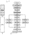
- FIGS 18 and 19 show the workflow which can be divided into the four basic steps of: Navigation/Preparation, Tibial Preparation, Ligament Balancing and Femoral Preparation.
- the first step of navigation/preparation is inserting the spoon-shaped positioning tool 1 with the attached bases 3a, 3b while the leg is in an extended state. Thereafter, the bases 3a, 3b are attached to the bone(s) 4, 5 using a single uni-cortical screw 8 for each bone, as shown in Fig. 4 . Thereafter, the spoon-shaped positioning tool 1 is removed and the reference arrays 10a, 10b are attached using a quick connect interface 10c to the bases 3a, 3b, as shown in Figures 6 and 7 .
- a further possibility is to insert the spoon 1 again with the slidable element 2 or element 2 being attached or fixed thereto while the leg is still in extension, to attach the cutting mechanism or cutting block 11 to the spoon 1 or element 2 and to adjust the cutting block 11 or mechanism to thereby adjust the tibial cut 5a. Thereafter, the spoon-like positioning tool 1 and element 2 is removed and the tibial cut 5a is performed.
- the tibial cut 5a can be verified and the cutting slots or cutting block 11 or cutting mechanism can be removed. Thereafter ligament balancing can optionally be performed, wherein the tibial array 10b has to be probably removed to attach the spreader array 10c to the tibial plate 12a of the spreader 12. Thereafter ligament balancing is performed as is known in the art.
- a mechanism can be attached to the spreader 12 and thereafter the femoral cut can be adjusted.
- a mechanism or cutting block 11 is attached to one of the array bases before the femoral cut is adjusted. It is also possible that the cutting block 11 or mechanism can be attached to the tibial and the femoral base, before the femoral cut is adjusted.
- the femoral cut is performed, verified and the cutting slot or cutting mechanism is removed.
- the implanting procedure can be started to implant the artificial joint, as known in the art.
Abstract
Description
- The present invention relates to a device, system and method for positioning a device or instrument, in particular positioning it relative to a system of coordinates or relative to a joint or a (bone) structure such as femur or tibia, or for positioning or preparing the position of a medical operating instrument, such as an incision block, a cutting block or a ligament balancing device.
- When attaching implants, such as artificial knee, elbow, finger or hip joints, it is required that the implant, such as a joint or part of a bone, is positioned as accurately as possible onto the adjacent bone. For this, the most accurate possible incisions must be made to the bone structures adjacent to the joint.
-
US 6,551,325 B2 of the applicant discloses that atibial incision block 100 is navigated onto a bone K using a positioning element inserted into the guide slit 100a. Then thisincision block 1 can be fixed to the bone K with suitable fixing or holding elements 101, as shown inFIG. 20 . Using acutting tool 102, a desired incision in the incision plane S0 can be made either by placing a blade on the upper side of theincision block 100, as shown inFigure 20A or by guiding a blade in the guide slit 100a, as shown inFIG. 20B . - A drill template can be positioned by a reference star on the incision plane S0 shown in
FIG. 20A in such a way that suitable tools for creating a connecting structure between the bone and the incision block, forexample holding elements 103, are inserted through holes into the bone K, such that asecond incision block 104, as shown inFIG. 21 , can be correctly positioned by attaching it to theholding elements 103. In the same way, aholding element 103 can for example also be firmly connected to theincision block 104 in such a way that theincision block 104 can be inserted into the holes, drilled into the bone K with the aid of the drill template, using theholding elements 103. Once thesecond incision block 104 has been placed in the desired position, the desired incisions in theplanes S 1 to S4 may be made, through the various guide slits provided in thesecond incision block 104. - An artificial joint can be attached onto the bone, in which the desired incision planes S0 to S4 have been created with the help of the
first incision block 100 and thesecond incision block 104, said joint being correctly positioned when the location of the incision planes S0 to S4 is correct. -
US 2006/0036257 A1 discloses a tibial spacer block used during knee arthroplasty configured to be temporarily positioned upon a resected proximal portion of a tibia for performing a range of motion analysis and for checking flexion and extension gaps prior to cutting the distal or posterior femur. The spacer block includes an attachment arrangement configured and arranged to mate with a complementary attachment arrangement of an alignment tower and/or a femoral cutting guide. The alignment tower, which is configured to be used with an alignment rod, is used for verifying the alignment of the limb's mechanical axis when the spacer block is positioned between the tibia and the femur. The femoral cutting guide is used for guiding a cutting member into proper orientation for resecting a distal or posterior portion of a femur. -
DE 103 35 388 A1 discloses that an area to be operated is connected to a navigation system with several transmitting and receiving devices. A marker in the shape of a rigid body is joined to the femur with a unit assembled of a sleeve and a holding element. The sleeve is fitted with a cylindrical extension with a conical tip, engaging with a matching recess located at a bone plate attached to the femur in order to facilitate a safe connection. -
DE 100 31 887 A1 -
US 4,566,448 discloses a ligament tensor and distal femoral resector guide which includes an adjustable support member for mounting on a tibial cutting guide including a guide slot in which is reciprocally mounted a slide member having an arm extending outward therefrom for engaging the condylar notch between the femoral condyles and a screw member threadably engaging the slide member for adjusting the position of the slide member and arm relative to the tibia cutting guide head for establishing tension in the ligaments of a knee structure. A flat pressure plate is removably mounted in the slots of the tibia cutting guide head for engaging the sectioned tibia plateau for applying pressure to the tibia for tensioning of the ligaments. A cutting guide head for guiding the resection of distal femoral condyles is mounted on the adjustable support member. -
US 2005/0149037 A1 discloses a cut block for cutting the femur and tibia during knee replacement surgery. -
US 5,911,723 discloses a surgical tensioning apparatus which has a base, first and second bone tissue engaging elements mounted on the base and being displaceable toward and away from each other. One of the tissue engaging elements being adapted to be oriented by the tissue engaged thereby. A guide element is provided which is adjustable in relation to the base and one of the tissue engaging elements for positioning a first location element to locate a cutting guide provided with cooperating second location element onto the bone to be resectioned. - It is the object of the present invention to propose a device, a system and a method for determining an initial position or the position of an instrument or device, such as an incision or cutting block, relative to a structure, e.g. a bone, especially relative to the femur and the tibia, whereby this determining of the position or finding of the initial position is simplified.
- This object is solved by the features of the independent claims. Advantageous embodiments arise from the dependent claims.
- A positioning or aligning device for aligning or positioning at least one and preferably two or even more devices or bases at a bone, such as for example the femur or the tibia, comprises a positioning tool which can have a spoon-like shape. This positioning tool is preferably an elongated element and is for example curved in a lateral direction and can have a rod-like shape. Preferably the cross-section of the positioning tool has a U-shaped form. The positioning tool is preferably not curved in the longitudinal direction and is connected to a positioning element which can be slideable, movable or relocatable on the positioning tool, preferably in the longitudinal direction of the positing tool. In an embodiment the positioning element can have a hole or guiding recess corresponding to the shape of the positioning tool and this hole can preferably have the shape corresponding to the cross section of the positing tool in the lateral direction, so that the positioning element is supported axially or longitudinal shiftable on the positioning element.
- The positioning tool having e.g. a spoon-like shape as mentioned above can be inserted into the joint, e.g. a knee gap, preferably after removing the cartilage, so that the positioning tool has preferably a stable position in the joint or knee gap being e.g. defined in a knee joint by the shape of the condyles of the femur, which are then placed in the concave-shaped portion of the positioning tool. On the opposite surface the positioning tool is abutting the tibia and thus, the spoon-like positioning tool can be held stable between the femur and the tibia when the leg is in a stretched or fully extended state.
- Having the positioning tool inserted into the joint, the positioning tool can preferably be exactly or about in a plane which is orthogonal to the longitudinal direction of the femur and/or the tibia, when the leg is in a fully extended or stretched state. After positioning the positioning tool, the positioning element can be shifted on the positioning tool until one or two bases being detachable connected to the positioning element are placed at or on a respective part of a bone, e.g. the femur and the tibia. The positioning tool can also be connected to the positioning element which can hold for example two bases and the positioning tool can be inserted into the joint or knee gap until one or each base held by the positioning element is located on or at the bones defining or forming the joint.
- The preferably spoon-like device can thus serve as an alignment instrument that is partly or fully pushed into the uncut knee joint gap. It aligns to the femoral condyle which defines thus the position of the tibial and the femoral array's base. This position should optimally be adjustable to different knee sizes.
- The position of the array bases on the alignment instrument is chosen in a way that, after the instrument is aligned in the joint gap and the bases are fixed to the bone, they prealign the cutting block. The cutting block therefore only needs fine adjustment and thus the navigation of the rough position on the bone can be omitted.
- In another version, the spoon can be extended by an interface to attach a cutting block mechanism directly to the spoon. After the adjustment, the cutting slot is fixated to the bone. The spoon with the attached mechanism is then removed from the bone or joint gap before performing the cut.
- The at least one positioning element comprises at least one and preferably two base holding parts, which can be arms or a hole through or in or pins at the positioning element. Preferably the base holding part is formed in a way to allow attachment or insertion of a base holding element, such as for example a base holding pin or hole, in only a single predefined orientation or direction. For example the base holding part can be a hole having a trapezoid-shape corresponding to a pin having a corresponding trapezoid-shape which allows insertion of the pin into the hole only in a single orientation.
- The positioning device can be used for a surgical method such as for example preparing an initial set-up of cutting blocks for generating one or more incision surfaces for an artificial joint, such as e.g. surfaces S0 to S4 shown in
Figures 20 and21 . The bases can be used for determining an initial orientation for cutting blocks or cutting jigs which can be attached to the bases and which are thus positioned at a bone in a predefined area or location on or at the bone, which eliminates the need of providing a workflow for finding a good or suitable position to place these cutting blocks by e.g. adjusting the position of these cutting blocks with the aid of reference stars. - Thus, the inventive positioning device can be used to reduce the number of steps when positioning a base for a surgical tool or when positioning the surgical tool itself, such as a cutting block, and hence the time needed for positioning a surgical tool and the invasiveness when attaching the surgical instruments to the bone can be reduced.
- A positioning system in accordance with the invention comprises a positioning device having a positioning tool and a positioning element as set forth above together with at least one and preferably two bases having holding elements, such as holes or pins, to be detachable connected to the positioning element, so that the base or bases can be positioned at a predefined location at a structure or bone with respect to the joint, using the positioning device. The bases can be fixed or attached to the respective structure or bone using e.g. a screw, preferably an uni-cortical screw, in a predefined orientation with respect to the bone and/or the joint. The positioning element can thereafter be removed together with the positioning tool, so that using the positioning device a predefined location for each base can easily be determined and found, which predefined location is preferably determined by the form of the positioning tool and the positioning element and is preferably selected to ensure that if the bone or bones at or to which the bases are attached are in a predefined state, such as e.g. a stretched leg, then navigation instruments, such as a reference star, and/or surgical tools, such as a cutting block or cutting jig, can be attached to the respective base and thus to a bone to have a good or optimal position for later navigation or surgical steps.
- Preferably reference elements or a reference star can be attached to each base being positioned using the positioning device to then have an orientation which enables a navigation system or camera to detect the reference elements in the predefined orientation determined by the position of the bases. If a patient and e.g. his leg has a known position and if there is a known position for e.g. an IR-camera, no complicated and time consuming setup has to be performed when using the invention for positioning and adjusting the orientation of reference stars at the respective bones to ensure e.g. good visibility of the reference stars.
- To fix the base(s) to the structure or bone, it is preferred to have an optimized screwdriver that allows for easy fixating the screws for the bases of the reference arrays, preferably having a magazine for screws to avoid difficult reloading of the screws.
- It is possible to provide a reference array base holder, which allows to simply attach the arrays if the use of the spoon-like tool is not possible. If array base and cutting block mechanism have the same interface, the tool can also be used for easily holding the cutting block mechanism in place.
- The array bases are preferably formed as bone plates that can be attached to the bone by screws that might be uni- or bicortical. The arrays can have spikes or protruding elements at the surface which contact the bone or can have e.g. a toothed surface to secure the respective base against rotation to avoid rotational movement on the bone when or after being attached.
- The bases are preferably designed in a way that soft tissue might cover part of the base after it has been attached to the bone to thus be a subcutaneous bone plate. The bone plates can have two different interfaces. One can be used for attaching a reference geometry and the other can be used to attach a cutting block. Both interfaces preferably prohibit rotational movement and are designed as quick-releasable connections.
- According to a further aspect of the invention, a ligament balancing device is provided which can guide a cutting device, such as a cutting block or a cutting jig. Alternatively, or in addition, the ligament balancing device can also be provided with or connected to a reference or tracking element, such as a tracking array, having for example three respective reference elements.
- The ligament balancing device has a spreader which can be extended by a tracking array that is fixedly mounted on the spreader, preferably on the spreader's tibial plateau. Due to the known position of the array on the spreader, the lowest plane of the spreader-paddles having contact to the cut tibial plane can be calculated. The plane then matches with the cut tibia plateau. This makes the previously attached reference array on the tibia unnecessary, because the cut tibia plane has been verified and therefore can be used as a reference plane.
- Furthermore, the spreader can be provided with the same interface as the array bases, so that the cutting block with the corresponding interface can also be attached to the spreader.
- Thus, the invention provides the advantage to improve the use of instruments used for total knee arthroplasty with respect to an optimized workflow having less duration and employing less complex instruments. Furthermore, the invasiveness can be decreased. The time for navigated surgeries can be shortened by diminishing the amount of navigational steps that have to be performed in a total knee arthroplasty.
- The alignment of the bases by the spoon is an easier way for the rough navigation of the cutting block and hence saves time. Furthermore, the location for the array bases is known. The arrays do not have to have joints that have to be adjusted, as the setup is predefined.
- Due to the combined bases to include interfaces for a reference array and for a cutting block, it is possible to reduce the amount of pins/screws/nails that are necessary, hence time is saved as well as the invasiveness is reduced.
- Regarding the invasiveness, the possibility of attaching the cutting block to the same fixation as the reference array not only saves additional drilling into the bone, but also eliminates the need for additional incisions. Furthermore, the length of the incision(s) might be reduced, as the area of contact between the bone and the baseplate is designed to lie subcutaneous.
- The invention will be further explained by reference to the accompanying drawings:
- Fig. 1
- shows the alignment of the bone plates using a spoon-shaped instrument as positioning tool;
- Fig. 2
- shows a drill guide as an optional improvement for attaching the bases;
- Fig. 3
- shows the drilling of the bone using the drill guide;
- Fig. 4
- shows the bases attached to the bone with one screw each;
- Fig. 5
- shows spikes on the back of the baseplate to block rotational movement;
- Fig. 6
- shows the alignment of the bases together with attached reference arrays on the tibia and the femur;
- Fig. 7
- shows a possibility to provide a quick-releasable attachment of the reference arrays to the bone plates;
- Fig. 8
- shows the attachment of a cutting block to the femoral baseplate;
- Fig. 9
- shows a version of the fine-adjusting mechanism for the cutting block that is provided with interfaces;
- Fig. 10
- shows a ligament-balancing device (spreader) onto which a tracking array has been fixedly attached;
- Figures 11 and 12
- show a ligament-balancing device that has been provided with an interface in order to receive and align a cutting block;
- Figures 13 to 17
- show the positioning tool in another version that is used for a sequential attachment of the bases. The long rod is meant for an alignment on the mechanical axis of the leg. After one base is fixated to the bone, the second base is attached to the tool and the tool is rotated by 180° and again aligned on the leg-axis.
- Fig. 18
- shows the first part of a workflow for a streamlined knee navigation in accordance with the invention;
- Fig. 19
- shows the second part of a workflow according to the invention;
- Figures 20A and 20B
- show the incision of a bone using a first cutting block positioned in accordance with the prior art; and
- Fig. 21
- shows the generation of further incision planes S1 to S4 using a second incision block positioned in accordance with the prior art.
-
Figure 1 shows the alignment of the bone plates orbases 3a and 3b on thefemur 4 and thetibia 5, respectively. The bone plates orbases 3a and 3b are arranged on and connected to thepositioning tool 1 being a spoon-shaped instrument that aligns itself on the anatomical structures of the femoral condyles. The spoon-shapedinstrument 1 is pushed into the joint gap of the knee between thefemur 4 and thetibia 5 in order to have a defined position and orientation with respect to thefemur 4 andtibia 5 when the leg is fully extended. Theslidable positioning element 2 is shiftable in a longitudinal direction on the spoon-shapedpositioning tool 1 and can in an alternative embodiment also be fixed to the spoon-shapedpositioning tool 1 and has two arms 2c, 2d extending away from thepositioning tool 1 having pins 2a, 2b being on one side of the arms 2c, 2d and further pins (not shown inFig. 1 ) extending in the opposite direction with respect to the arms 2c, 2d, to which thebases 3a and 3b are detachably attached in a predefined orientation being determined by the shape of the pins to which thebases 3a and 3b are attached using theholes 3d (shown inFig. 6 ). When theslidable positioning element 2 is shifted toward thebones bases 3a and 3b are brought with a predefined orientation, determined by the position of thepositioning tool 1, into contact with thefemur 4 and thetibia 5. - Each
base 3a, 3b is provided with an opening or a hole 3c, which can be used as guidance for adrill guide 6, as shown inFigure 2 , which can be used in case the guiding length of the holes 3c in thebasplate 3a, 3b is not long enough to guide adrill 7 properly. Thedrill guide 6 is inserted into each hole 3c of thebases 3a, 3b to provide a guide for adrill 7, as shown inFigure 3 , to drill a hole into thefemur 4 and thetibia 5 to fix thebases 3a, 3b after removing thedrill guide 6 and thedrill 7, using asingle screw 8, as shown inFig. 4 . - As shown in
Fig. 5 , spikes or a toothed surface havingtoothed elements 9 can be provided at the surface of eachbase 3a, 3b to prevent rotational movement of therespective base 3a, 3b after being attached to arespective bone screw 8 is screwed in. - After the
bases 3a and 3b have been fixed to thebones positioning tool 1 can be removed together with thepositioning element 2, so that thebases 3a and 3b are only held at thebones screws 8 and optionally using thespikes 9 or a toothed surface to prevent rotation. - As shown in
Fig. 6 , thebases 3a, 3b can be further aligned with reference arrays 10a and 10b being attached to thebases 3a, 3b using a sliding and fixable connection 10c as shown inFig. 7 . It is possible to first insert thescrews 8 for roughly aligning or attaching thebases 3a and 3b and to fully fix thebases 3a, 3b after having them aligned with reference arrays 10a, 10b by tightening thescrews 8. - After the
bases 3 a and 3b have been aligned, a cuttingblock 11 having a slot 11a for guiding a cutting blade can be attached to one baseplate, e.g. the femoral baseplate 3a. To provide connectability to the cuttingblock 11, the base or bone plate 3a is supported with an interface that fits to the interface of the cuttingblock 11 and that is locked against rotation. - The reference arrays 10a, 10b can have a quick connect interface 10c. In order to attach the arrays 10a, 10b to a baseplate attached below the skin, the leg shall be moved to extension where the incision can be moved aside, so that the baseplate can be attached. After the bone plate has been fixated, the soft tissue lies over the baseplate. The higher parts of the baseplate also have a retracting function to the soft tissue.
-
Fig. 9 shows a version of a fine adjustable mechanism of the cuttingblock 11 that is provided with interfaces 11b, 11c. Depending on which knee joint, i.e. the left or the right knee joint, is to be replaced, the left or the right interface 11b, 11c can be used. The cuttingblock 11 can be attached for generating the tibial cut in one of the following ways. - The spoon-like positioning tool can be inserted again with the leg being in extension. Probably the
positioning tool 1 is fixed with one additional screw, such as a uni-cortical screw. Then the cutting block is 11 is attached. - Having the mechanism on the femoral side, by this the femoral array could be detached to have space for the mechanism for the tibial cut, or the femoral array can be removed and the mechanism for the tibial cut can be attached to the base of the femoral array. Alternatively, the mechanism for the tibial cut can be attached to the tibial base that contains an interface that fits an according interface at the mechanism.
- Thereafter the tibial cutting block or cutting
jig 11 is fixed with at least two pins, nails or screws, which can be inserted trough openings 11d and 11e to thetibia 5. - Thereafter, the spoon-shaped
positioning tool 1 can be removed from the base with or without the mechanism, if necessary, and the tibial cut can be performed. - After performing the tibial cut, ligament balancing can be performed in flexion and extension using the
ligament balancing device 12 as shown inFig. 10 provided with a tracking array 10c. Theligament balancing device 12 is inserted into the joint gap and/or can be attached to the tibia component. Theligament balancing device 12 or spreader provided with the tracking array 10c provides the possibility to calculate the position of the underside of the spreadingpaddles 12a, 12b and thus the orientation of the cut-plateau 5a of thetibia 5 which has been verified previously. - As shown in
Fig. 11 , the ligament-balancingdevice 12 or spreader can be provided with or connected to aninterface 13 in order to receive or attach afemur cutting block 11, which can be the same cutting block as described above. -
Fig. 12 shows theligament balancing device 12 inserted into the joint gap with the attached cuttingblock 11. -
Figures 13 to 17 show a modified workflow, wherein the array bases are not inserted or attached simultaneously or almost simultaneously, but instead one after another. The positioning tool is formed like a rod having preferably a circular cross section, so that the tool can be rotated around the axis of this rod after the first base has been attached to align and attach the second base. - To provide an alignment with respect to the anatomical structures, an aiming device in the form of a long rod is attached. This rod can be pointed to the femur head or the ankle joint depending on which base should be attached. This enables a rough alignment of the bases, since the desired cutting plane is measured with respect to the mechanical leg axis which runs from the femur head to the ankle joints.
-
Figures 18 and19 show the workflow which can be divided into the four basic steps of: Navigation/Preparation, Tibial Preparation, Ligament Balancing and Femoral Preparation. - Starting with the streamlined knee navigation, the first step of navigation/preparation is inserting the spoon-shaped
positioning tool 1 with the attachedbases 3a, 3b while the leg is in an extended state. Thereafter, thebases 3a, 3b are attached to the bone(s) 4, 5 using a singleuni-cortical screw 8 for each bone, as shown inFig. 4 . Thereafter, the spoon-shapedpositioning tool 1 is removed and the reference arrays 10a, 10b are attached using a quick connect interface 10c to thebases 3a, 3b, as shown inFigures 6 and7 . - Thereafter, a registration procedure is performed, as is known in the art.
- In principal three possibilities exist to prepare the
tibial cut 5a shown inFigure 12 . One possibility is to attach acutting block 11 or cutting mechanism to thetibial base 3b, to adjust the cuttingblock 11 to thus adjust thetibial cut 5a and to fixate the cuttingblock 11 e.g. using holes 11d, 11e. - A further possibility is to insert the
spoon 1 again with theslidable element 2 orelement 2 being attached or fixed thereto while the leg is still in extension, to attach the cutting mechanism or cuttingblock 11 to thespoon 1 orelement 2 and to adjust the cuttingblock 11 or mechanism to thereby adjust thetibial cut 5a. Thereafter, the spoon-like positioning tool 1 andelement 2 is removed and thetibial cut 5a is performed. - A further possibility exists according to which the
cutting block 11 or mechanism is attached to the femoral base 3a and thetibial cut 5a is adjusted. Thereafter, thetibial cut 5a is performed. - The
tibial cut 5a can be verified and the cutting slots or cuttingblock 11 or cutting mechanism can be removed. Thereafter ligament balancing can optionally be performed, wherein the tibial array 10b has to be probably removed to attach the spreader array 10c to thetibial plate 12a of thespreader 12. Thereafter ligament balancing is performed as is known in the art. - In case the
spreader 12 remains attached, a mechanism can be attached to thespreader 12 and thereafter the femoral cut can be adjusted. In case thespreader 12 does not remain in the joint, a mechanism or cuttingblock 11 is attached to one of the array bases before the femoral cut is adjusted. It is also possible that the cuttingblock 11 or mechanism can be attached to the tibial and the femoral base, before the femoral cut is adjusted. - Thereafter, the femoral cut is performed, verified and the cutting slot or cutting mechanism is removed.
- After performing this step of femoral preparation, the implanting procedure can be started to implant the artificial joint, as known in the art.
Claims (17)
- Positioning device for aligning or positioning at least one device or base (3a, 3b) at at least one structure or bone (4,5) comprising a positioning tool (1) and a positioning element (2) having at least one base holding part (2a-2d), to which at least one device or base (3a, 3b) can detachably be attached.
- Positioning device according to claim 1, wherein the positioning tool (1) is curved in a lateral direction and/or has a spoon-like shape.
- Positioning device according to one of the preceding claims, wherein the positioning element (2) is slidable, movable or relocatable on or with respect to the positioning tool (1).
- Positioning device according to one of the preceding claims, wherein the base holding part comprises at least one pin (2a, 2b) or hole.
- Positioning device according to one of the preceding claims, wherein the base holding part or a pin (2a, 2b) or hole is formed to allow connection in only a single predefined orientation.
- Positioning system for aligning or positioning at least one device or base (3a, 3b) at one or more structures or bones (4, 5) comprising a positioning device according to one of the preceding claims and at least one base (3a, 3b) having a holding or orientation element (3c) to be detachably connected to the positioning device.
- Positioning system according to the previous claim, wherein the holding or orientation element (3c) of the base (3a, 3b) is a hole or a pin.
- Positioning system according to one of the two preceding claims, wherein at least one base (3a, 3b) has a surface having projections (9) or has a toothed surface.
- Positioning system according to one of three preceding claims further comprising a drill guide (6).
- Positioning system according to one of the four preceding claims further comprising at least one reference array (10a, 10b).
- Positioning system according to one of the five preceding claims further comprising a cutting block (11).
- Ligament balancing device (12) having at least one reference element or reference array (10c).
- Ligament balancing device (12) having or being connected to a cutting block (11).
- Ligament balancing device (12) having at least one reference element or reference array (10c) being capable of replacing at least one reference element or reference array.
- Method for aligning or positioning at least one base (3a, 3b) at a structure or bone (4, 5) comprising the following steps:inserting a positioning tool (1) with attached base or bases (3a, 3b) into a joint to thereby provide an initial orientation of the tool (1) with respect to the joint and/or the structure or bones (4, 5);attaching the base or bases (3a, 3c) to the structure or bone (4,5); andremoving the positioning tool (1).
- Method according to the preceding claim, further comprising the step of attaching an array (10a, 10b) to each base (3a, 3b).
- Method for preparing a second cut at a second bone (4) after a first cut at a first bone (5) of a joint has been made, wherein ligament balancing is performed and the orientation of the second cut is determined with respect to the orientation of the first cut and the position of the second bone (4) being determined by a ligament balancing device (12).
Priority Applications (2)
| Application Number | Priority Date | Filing Date | Title |
|---|---|---|---|
| EP07102301.4A EP1958575B1 (en) | 2007-02-13 | 2007-02-13 | Device or system for positioning or preparing the positioning of a medical operating instrument, especially an incision block or a cutting block or a ligament balancing device |
| US12/030,302 US8945132B2 (en) | 2007-02-13 | 2008-02-13 | Device, system and method for positioning or preparing the positioning of a medical operating instrument |
Applications Claiming Priority (1)
| Application Number | Priority Date | Filing Date | Title |
|---|---|---|---|
| EP07102301.4A EP1958575B1 (en) | 2007-02-13 | 2007-02-13 | Device or system for positioning or preparing the positioning of a medical operating instrument, especially an incision block or a cutting block or a ligament balancing device |
Publications (2)
| Publication Number | Publication Date |
|---|---|
| EP1958575A1 true EP1958575A1 (en) | 2008-08-20 |
| EP1958575B1 EP1958575B1 (en) | 2014-08-13 |
Family
ID=38283335
Family Applications (1)
| Application Number | Title | Priority Date | Filing Date |
|---|---|---|---|
| EP07102301.4A Active EP1958575B1 (en) | 2007-02-13 | 2007-02-13 | Device or system for positioning or preparing the positioning of a medical operating instrument, especially an incision block or a cutting block or a ligament balancing device |
Country Status (2)
| Country | Link |
|---|---|
| US (1) | US8945132B2 (en) |
| EP (1) | EP1958575B1 (en) |
Cited By (1)
| Publication number | Priority date | Publication date | Assignee | Title |
|---|---|---|---|---|
| WO2015181188A1 (en) * | 2014-05-27 | 2015-12-03 | Aesculap Ag | Medical system |
Families Citing this family (36)
| Publication number | Priority date | Publication date | Assignee | Title |
|---|---|---|---|---|
| KR100528121B1 (en) * | 2003-03-27 | 2005-11-15 | 김종범 | Determinating device of size of atrificial knee joint |
| EP2273922A1 (en) * | 2008-04-25 | 2011-01-19 | Ross G. Stone | Navigation tracker fixation device and method for use thereof |
| US9918724B2 (en) | 2012-12-27 | 2018-03-20 | Wright Medical Technology, Inc. | Ankle replacement system and method |
| US9993273B2 (en) | 2013-01-16 | 2018-06-12 | Mako Surgical Corp. | Bone plate and tracking device using a bone plate for attaching to a patient's anatomy |
| US9566120B2 (en) | 2013-01-16 | 2017-02-14 | Stryker Corporation | Navigation systems and methods for indicating and reducing line-of-sight errors |
| WO2014124239A1 (en) * | 2013-02-08 | 2014-08-14 | Orthopaedic International, Inc. | Prosthetic implants for total knee arthroplasty |
| US9427240B2 (en) * | 2013-03-21 | 2016-08-30 | Von Zabern Surgical | System and method for performing measurable and controled osteotomy |
| US20160015426A1 (en) | 2014-07-15 | 2016-01-21 | Treace Medical Concepts, Inc. | Bone positioning and cutting system and method |
| CN106999213B (en) * | 2014-10-29 | 2019-11-08 | 乔纳森·彼得·卡伯特 | The device and method for being used to prepare the shin bone proximal surface of the tibial component of knee-joint prosthesis |
| US9687250B2 (en) | 2015-01-07 | 2017-06-27 | Treace Medical Concepts, Inc. | Bone cutting guide systems and methods |
| US10849631B2 (en) | 2015-02-18 | 2020-12-01 | Treace Medical Concepts, Inc. | Pivotable bone cutting guide useful for bone realignment and compression techniques |
| USD823470S1 (en) * | 2015-07-10 | 2018-07-17 | Brainlab Ag | Reference array |
| US10849663B2 (en) | 2015-07-14 | 2020-12-01 | Treace Medical Concepts, Inc. | Bone cutting guide systems and methods |
| US9622805B2 (en) | 2015-08-14 | 2017-04-18 | Treace Medical Concepts, Inc. | Bone positioning and preparing guide systems and methods |
| AU2016294588B2 (en) | 2015-07-14 | 2021-06-17 | Treace Medical Concepts, Inc. | Bone positioning guide |
| US11278337B2 (en) | 2015-08-14 | 2022-03-22 | Treace Medical Concepts, Inc. | Tarsal-metatarsal joint procedure utilizing fulcrum |
| WO2017031020A1 (en) | 2015-08-14 | 2017-02-23 | Treace Medical Concepts, Inc. | Tarsal-metatarsal joint procedure utilizing fulcrum |
| EP3349674A4 (en) * | 2015-09-18 | 2019-05-22 | Treace Medical Concepts, Inc. | Joint spacer systems and methods |
| US10973659B2 (en) * | 2016-04-22 | 2021-04-13 | Jonathan Peter Cabot | Arrangement and method used in the preparation of the proximal surface of the tibia for the tibia component of a prosthetic knee joint |
| US10537395B2 (en) | 2016-05-26 | 2020-01-21 | MAKO Surgical Group | Navigation tracker with kinematic connector assembly |
| US10512470B1 (en) | 2016-08-26 | 2019-12-24 | Treace Medical Concepts, Inc. | Osteotomy procedure for correcting bone misalignment |
| US10582936B1 (en) | 2016-11-11 | 2020-03-10 | Treace Medical Concepts, Inc. | Devices and techniques for performing an osteotomy procedure on a first metatarsal to correct a bone misalignment |
| WO2018119360A1 (en) | 2016-12-22 | 2018-06-28 | Orthosensor Inc. | Surgical apparatus to support installation of a prosthetic component and method therefore |
| US11266512B2 (en) | 2016-12-22 | 2022-03-08 | Orthosensor Inc. | Surgical apparatus to support installation of a prosthetic component and method therefore |
| US11284873B2 (en) | 2016-12-22 | 2022-03-29 | Orthosensor Inc. | Surgical tensor where each distraction mechanism is supported and aligned by at least two guide shafts |
| US11291437B2 (en) | 2016-12-22 | 2022-04-05 | Orthosensor Inc. | Tilting surgical tensor to support at least one bone cut |
| US11185425B2 (en) | 2016-12-22 | 2021-11-30 | Orthosensor Inc. | Surgical tensor configured to distribute loading through at least two pivot points |
| WO2020014457A1 (en) | 2018-07-11 | 2020-01-16 | Treace Medical Concepts, Inc. | Compressor-distractor for angularly realigning bone portions |
| WO2020014660A1 (en) | 2018-07-12 | 2020-01-16 | Treace Medical Concepts, Inc. | Multi-diameter bone pin for installing and aligning bone fixation plate while minimizing bone damage |
| US11607250B2 (en) | 2019-02-13 | 2023-03-21 | Treace Medical Concepts, Inc. | Tarsal-metatarsal joint procedure utilizing compressor-distractor and instrument providing sliding surface |
| US11627954B2 (en) | 2019-08-07 | 2023-04-18 | Treace Medical Concepts, Inc. | Bi-planar instrument for bone cutting and joint realignment procedure |
| US11889998B1 (en) | 2019-09-12 | 2024-02-06 | Treace Medical Concepts, Inc. | Surgical pin positioning lock |
| EP4027922A4 (en) | 2019-09-13 | 2023-10-04 | MIOS Marketing LLC, DBA RedPoint Medical 3D | Patient-specific surgical methods and instrumentation |
| US11890039B1 (en) | 2019-09-13 | 2024-02-06 | Treace Medical Concepts, Inc. | Multi-diameter K-wire for orthopedic applications |
| WO2021155269A1 (en) | 2020-01-31 | 2021-08-05 | Treace Medical Concepts, Inc. | Metatarsophalangeal joint preparation and metatarsal realignment for fusion |
| USD1011524S1 (en) | 2022-02-23 | 2024-01-16 | Treace Medical Concepts, Inc. | Compressor-distractor for the foot |
Citations (7)
| Publication number | Priority date | Publication date | Assignee | Title |
|---|---|---|---|---|
| WO2001066021A1 (en) * | 2000-03-10 | 2001-09-13 | Smith & Nephew, Inc | A method of arthroplasty on a knee joint and apparatus for use in same |
| US20020068942A1 (en) * | 2000-09-26 | 2002-06-06 | Timo Neubauer | Device, system and method for determining the positon of an incision block |
| WO2004019792A1 (en) * | 2002-08-27 | 2004-03-11 | Smith & Nephew, Inc. | Computer assisted knee arthroplasty instrumentation, system, and process |
| DE10335388A1 (en) * | 2003-07-25 | 2005-02-24 | Aesculap Ag & Co. Kg | Surgical reference device, comprising bone plate attached to femur for safe joining of rigid body |
| US20050096535A1 (en) * | 2003-11-04 | 2005-05-05 | De La Barrera Jose Luis M. | System and method of registering image data to intra-operatively digitized landmarks |
| EP1574170A1 (en) * | 2004-03-08 | 2005-09-14 | BrainLAB AG | Adjustable working aid for treatment of bones |
| EP1690503A1 (en) * | 2005-02-15 | 2006-08-16 | BrainLAB AG | User guidance for adjusting the cutting guides for the bones |
Family Cites Families (41)
| Publication number | Priority date | Publication date | Assignee | Title |
|---|---|---|---|---|
| US4567886A (en) * | 1983-01-06 | 1986-02-04 | Petersen Thomas D | Flexion spacer guide for fitting a knee prosthesis |
| US4566448A (en) * | 1983-03-07 | 1986-01-28 | Rohr Jr William L | Ligament tensor and distal femoral resector guide |
| US5116338A (en) | 1988-02-03 | 1992-05-26 | Pfizer Hospital Products Group, Inc. | Apparatus for knee prosthesis |
| US5296646A (en) * | 1992-04-03 | 1994-03-22 | The Whitaker Corporation | Protector module for telephone line junction box |
| DE4423717C1 (en) * | 1994-07-08 | 1996-01-04 | Eska Medical Gmbh & Co | Device for determining resection surfaces on the femur and on the tibia for preparing an implantation of a total knee joint endoprosthesis |
| US5540696A (en) | 1995-01-06 | 1996-07-30 | Zimmer, Inc. | Instrumentation for use in orthopaedic surgery |
| US5662656A (en) * | 1995-12-08 | 1997-09-02 | Wright Medical Technology, Inc. | Instrumentation and method for distal femoral sizing, and anterior and distal femoral resections |
| US5669914A (en) | 1996-02-16 | 1997-09-23 | Board Of Regents Of The University Of Colorado | Rotation alignment instrument |
| GB9611074D0 (en) | 1996-05-28 | 1996-07-31 | Howmedica | Surgical apparatus |
| US6106529A (en) * | 1998-12-18 | 2000-08-22 | Johnson & Johnson Professional, Inc. | Epicondylar axis referencing drill guide |
| US6296646B1 (en) | 2000-06-29 | 2001-10-02 | Richard V. Williamson | Instruments and methods for use in performing knee surgery |
| US6478799B1 (en) * | 2000-06-29 | 2002-11-12 | Richard V. Williamson | Instruments and methods for use in performing knee surgery |
| DE10031887B4 (en) | 2000-06-30 | 2008-02-07 | Stryker Leibinger Gmbh & Co. Kg | System for implantation of knee joint prostheses |
| US6468280B1 (en) * | 2000-07-24 | 2002-10-22 | Sulzer Orthopedics Inc. | Unicompartmental replacement instrument and method |
| CA2354747A1 (en) | 2000-08-08 | 2002-02-08 | Depuy Acromed, Inc. | Spinal rod/plate locking mechanisms and surgical methods |
| FR2814668B1 (en) | 2000-09-29 | 2003-03-14 | Bertrand Lombard | TRANSMITTER BLOCK HOLDER DEVICE AND RELATED SURGICAL NAVIGATION METHOD AND DEVICE |
| US6558391B2 (en) | 2000-12-23 | 2003-05-06 | Stryker Technologies Corporation | Methods and tools for femoral resection in primary knee surgery |
| US6685711B2 (en) | 2001-02-28 | 2004-02-03 | Howmedica Osteonics Corp. | Apparatus used in performing femoral and tibial resection in knee surgery |
| FR2826254B1 (en) | 2001-06-25 | 2004-06-18 | Aesculap Sa | DEVICE FOR POSITIONING A CUTTING PLAN OF A BONE CUTTING GUIDE |
| US7618421B2 (en) | 2001-10-10 | 2009-11-17 | Howmedica Osteonics Corp. | Tools for femoral resection in knee surgery |
| US7060074B2 (en) | 2001-11-28 | 2006-06-13 | Wright Medical Technology, Inc. | Instrumentation for minimally invasive unicompartmental knee replacement |
| CA2474967C (en) | 2002-03-05 | 2009-09-29 | Nemcomed, Inc. | Minimally invasive total knee arthroplasty method and instrumentation |
| US6758850B2 (en) | 2002-03-29 | 2004-07-06 | Depuy Orthopaedics, Inc. | Instruments and methods for flexion gap adjustment |
| US7029477B2 (en) * | 2002-12-20 | 2006-04-18 | Zimmer Technology, Inc. | Surgical instrument and positioning method |
| KR100528121B1 (en) * | 2003-03-27 | 2005-11-15 | 김종범 | Determinating device of size of atrificial knee joint |
| DE50303568D1 (en) * | 2003-04-25 | 2006-07-06 | Zimmer Gmbh | Device for preparing a femoral condyle |
| US7313430B2 (en) * | 2003-08-28 | 2007-12-25 | Medtronic Navigation, Inc. | Method and apparatus for performing stereotactic surgery |
| US7862570B2 (en) * | 2003-10-03 | 2011-01-04 | Smith & Nephew, Inc. | Surgical positioners |
| DE602004031147D1 (en) | 2003-11-14 | 2011-03-03 | Smith & Nephew Inc | |
| US7282054B2 (en) | 2003-12-26 | 2007-10-16 | Zimmer Technology, Inc. | Adjustable cut block |
| US7364581B2 (en) | 2004-01-14 | 2008-04-29 | Howmedica Osteonics Corp. | Variable angle cutting block |
| US7641660B2 (en) | 2004-03-08 | 2010-01-05 | Biomet Manufacturing Corporation | Method, apparatus, and system for image guided bone cutting |
| US20050267482A1 (en) | 2004-04-22 | 2005-12-01 | Hyde Edward R Jr | Bone treatment method with implants and instrumentation |
| EP1598021B1 (en) | 2004-05-17 | 2006-06-28 | Zimmer GmbH | Device for positioning of guide block for tibial resection |
| US8167888B2 (en) | 2004-08-06 | 2012-05-01 | Zimmer Technology, Inc. | Tibial spacer blocks and femoral cutting guide |
| US7377924B2 (en) | 2004-09-09 | 2008-05-27 | Howmedica Osteonics Corp. | Navigated drill guided resection block |
| DE102004046414B4 (en) | 2004-09-24 | 2006-10-12 | Stryker Leibinger Gmbh & Co. Kg | Surgical anchoring device |
| US20060155294A1 (en) | 2005-01-11 | 2006-07-13 | Zimmer Technology, Inc. | Tibial/femoral recutter with paddle |
| US20060235290A1 (en) | 2005-04-04 | 2006-10-19 | Aesculap Ag & Co. Kg | Method and apparatus for positioning a cutting tool for orthopedic surgery using a localization system |
| US7601154B2 (en) * | 2005-04-18 | 2009-10-13 | Uni-Knee, Llc | Unicondylar knee instrument system |
| US8162949B2 (en) * | 2008-04-21 | 2012-04-24 | Biomet Manufacturing Corp. | Tibial resection guide |
-
2007
- 2007-02-13 EP EP07102301.4A patent/EP1958575B1/en active Active
-
2008
- 2008-02-13 US US12/030,302 patent/US8945132B2/en active Active
Patent Citations (7)
| Publication number | Priority date | Publication date | Assignee | Title |
|---|---|---|---|---|
| WO2001066021A1 (en) * | 2000-03-10 | 2001-09-13 | Smith & Nephew, Inc | A method of arthroplasty on a knee joint and apparatus for use in same |
| US20020068942A1 (en) * | 2000-09-26 | 2002-06-06 | Timo Neubauer | Device, system and method for determining the positon of an incision block |
| WO2004019792A1 (en) * | 2002-08-27 | 2004-03-11 | Smith & Nephew, Inc. | Computer assisted knee arthroplasty instrumentation, system, and process |
| DE10335388A1 (en) * | 2003-07-25 | 2005-02-24 | Aesculap Ag & Co. Kg | Surgical reference device, comprising bone plate attached to femur for safe joining of rigid body |
| US20050096535A1 (en) * | 2003-11-04 | 2005-05-05 | De La Barrera Jose Luis M. | System and method of registering image data to intra-operatively digitized landmarks |
| EP1574170A1 (en) * | 2004-03-08 | 2005-09-14 | BrainLAB AG | Adjustable working aid for treatment of bones |
| EP1690503A1 (en) * | 2005-02-15 | 2006-08-16 | BrainLAB AG | User guidance for adjusting the cutting guides for the bones |
Cited By (4)
| Publication number | Priority date | Publication date | Assignee | Title |
|---|---|---|---|---|
| WO2015181188A1 (en) * | 2014-05-27 | 2015-12-03 | Aesculap Ag | Medical system |
| CN106413591A (en) * | 2014-05-27 | 2017-02-15 | 阿斯卡拉波股份有限公司 | Medical system |
| CN106413591B (en) * | 2014-05-27 | 2019-06-04 | 阿斯卡拉波股份有限公司 | Medical system |
| US10675096B2 (en) | 2014-05-27 | 2020-06-09 | Aesculap Ag | Medical system |
Also Published As
| Publication number | Publication date |
|---|---|
| US20080195110A1 (en) | 2008-08-14 |
| US8945132B2 (en) | 2015-02-03 |
| EP1958575B1 (en) | 2014-08-13 |
Similar Documents
| Publication | Publication Date | Title |
|---|---|---|
| EP1958575B1 (en) | Device or system for positioning or preparing the positioning of a medical operating instrument, especially an incision block or a cutting block or a ligament balancing device | |
| US11490902B2 (en) | Patient specific instrumentation (PSI) for orthopedic surgery and systems and methods for using X-rays to produce same | |
| AU696251B2 (en) | Distal femoral cutting guide | |
| US9795392B2 (en) | Surgical instrumentation set and surgical technique | |
| US6554837B1 (en) | Device and method for inserting a prosthetic knee | |
| EP2953559B1 (en) | Total knee arthroplasty systems | |
| AU2005296761B2 (en) | Ligament-tensioning device, cutting jig and osteotomy method | |
| US4938762A (en) | Reference system for implantation of condylar total knee prostheses | |
| JP3804975B2 (en) | Tibial resection instrument | |
| AU2004201721B2 (en) | An apparatus for the preparation of a femoral condyle | |
| US20050256527A1 (en) | Ligament tensioning device with cutting jig, and osteotomy method | |
| US20110046685A1 (en) | Surgical instrument for fitting a knee prosthesis | |
| US20060195111A1 (en) | Universal positioning block assembly | |
| AU2004201717B2 (en) | An apparatus for the preparation of a femoral condyle | |
| JP2003503096A (en) | Tibial plateau resection guide | |
| WO1997030640A9 (en) | Distal femoral cutting guide apparatus | |
| JP2009511211A (en) | Osteotomy-systems and methods | |
| US20160045268A1 (en) | Surgical plan options for robotic machining | |
| JP5646627B2 (en) | Stylus assembly | |
| WO2018213835A1 (en) | Cut guide system | |
| US11872142B2 (en) | Gap balancing assembly for knee revision surgery | |
| CN211156059U (en) | Customized ankle osteotomy guide plate device | |
| JP2019506997A (en) | Cutting guide device which can be positioned at all positions in the intramedullary base for femoral end resection for knee prosthesis placement and its operating method | |
| EP1836975A1 (en) | A surgical instrument for locating a cutting plane on a bone |
Legal Events
| Date | Code | Title | Description |
|---|---|---|---|
| PUAI | Public reference made under article 153(3) epc to a published international application that has entered the european phase |
Free format text: ORIGINAL CODE: 0009012 |
|
| 17P | Request for examination filed |
Effective date: 20070213 |
|
| AK | Designated contracting states |
Kind code of ref document: A1 Designated state(s): AT BE BG CH CY CZ DE DK EE ES FI FR GB GR HU IE IS IT LI LT LU LV MC NL PL PT RO SE SI SK TR |
|
| AX | Request for extension of the european patent |
Extension state: AL BA HR MK RS |
|
| 17Q | First examination report despatched |
Effective date: 20081008 |
|
| AKX | Designation fees paid |
Designated state(s): DE FR |
|
| RAP1 | Party data changed (applicant data changed or rights of an application transferred) |
Owner name: BRAINLAB AG |
|
| GRAP | Despatch of communication of intention to grant a patent |
Free format text: ORIGINAL CODE: EPIDOSNIGR1 |
|
| INTG | Intention to grant announced |
Effective date: 20140508 |
|
| GRAS | Grant fee paid |
Free format text: ORIGINAL CODE: EPIDOSNIGR3 |
|
| GRAA | (expected) grant |
Free format text: ORIGINAL CODE: 0009210 |
|
| AK | Designated contracting states |
Kind code of ref document: B1 Designated state(s): DE FR |
|
| REG | Reference to a national code |
Ref country code: DE Ref legal event code: R096 Ref document number: 602007038055 Country of ref document: DE Effective date: 20140918 |
|
| REG | Reference to a national code |
Ref country code: DE Ref legal event code: R097 Ref document number: 602007038055 Country of ref document: DE |
|
| PLBE | No opposition filed within time limit |
Free format text: ORIGINAL CODE: 0009261 |
|
| STAA | Information on the status of an ep patent application or granted ep patent |
Free format text: STATUS: NO OPPOSITION FILED WITHIN TIME LIMIT |
|
| 26N | No opposition filed |
Effective date: 20150515 |
|
| REG | Reference to a national code |
Ref country code: FR Ref legal event code: PLFP Year of fee payment: 10 |
|
| REG | Reference to a national code |
Ref country code: FR Ref legal event code: PLFP Year of fee payment: 11 |
|
| REG | Reference to a national code |
Ref country code: DE Ref legal event code: R082 Ref document number: 602007038055 Country of ref document: DE Representative=s name: MURGITROYD & COMPANY, DE Ref country code: DE Ref legal event code: R081 Ref document number: 602007038055 Country of ref document: DE Owner name: SMITH & NEPHEW PTE. LIMITED, SG Free format text: FORMER OWNER: BRAINLAB AG, 85622 FELDKIRCHEN, DE Ref country code: DE Ref legal event code: R081 Ref document number: 602007038055 Country of ref document: DE Owner name: SMITH & NEPHEW ORTHOPAEDICS AG, CH Free format text: FORMER OWNER: BRAINLAB AG, 85622 FELDKIRCHEN, DE Ref country code: DE Ref legal event code: R081 Ref document number: 602007038055 Country of ref document: DE Owner name: SMITH & NEPHEW, INC., WILMINGTON, US Free format text: FORMER OWNER: BRAINLAB AG, 85622 FELDKIRCHEN, DE Ref country code: DE Ref legal event code: R081 Ref document number: 602007038055 Country of ref document: DE Owner name: SMITH & NEPHEW ASIA PACIFIC PTE LIMITED, SG Free format text: FORMER OWNER: BRAINLAB AG, 85622 FELDKIRCHEN, DE Ref country code: DE Ref legal event code: R082 Ref document number: 602007038055 Country of ref document: DE Representative=s name: SCHWABE SANDMAIR MARX PATENTANWAELTE RECHTSANW, DE Ref country code: DE Ref legal event code: R081 Ref document number: 602007038055 Country of ref document: DE Owner name: BRAINLAB AG, DE Free format text: FORMER OWNER: BRAINLAB AG, 85622 FELDKIRCHEN, DE Ref country code: DE Ref legal event code: R082 Ref document number: 602007038055 Country of ref document: DE Representative=s name: SSM SANDMAIR PATENTANWAELTE RECHTSANWALT PARTN, DE |
|
| REG | Reference to a national code |
Ref country code: FR Ref legal event code: CA Effective date: 20170706 |
|
| REG | Reference to a national code |
Ref country code: FR Ref legal event code: PLFP Year of fee payment: 12 |
|
| REG | Reference to a national code |
Ref country code: DE Ref legal event code: R082 Ref document number: 602007038055 Country of ref document: DE Representative=s name: MURGITROYD GERMANY PATENTANWALTSGESELLSCHAFT M, DE Ref country code: DE Ref legal event code: R082 Ref document number: 602007038055 Country of ref document: DE Representative=s name: MURGITROYD & COMPANY, DE |
|
| REG | Reference to a national code |
Ref country code: DE Ref legal event code: R082 Ref document number: 602007038055 Country of ref document: DE Representative=s name: MURGITROYD & COMPANY, DE Ref country code: DE Ref legal event code: R081 Ref document number: 602007038055 Country of ref document: DE Owner name: SMITH & NEPHEW PTE. LIMITED, SG Free format text: FORMER OWNER: BRAINLAB AG, 81829 MUENCHEN, DE Ref country code: DE Ref legal event code: R081 Ref document number: 602007038055 Country of ref document: DE Owner name: SMITH & NEPHEW, INC., WILMINGTON, US Free format text: FORMER OWNER: BRAINLAB AG, 81829 MUENCHEN, DE Ref country code: DE Ref legal event code: R081 Ref document number: 602007038055 Country of ref document: DE Owner name: SMITH & NEPHEW ORTHOPAEDICS AG, CH Free format text: FORMER OWNER: BRAINLAB AG, 81829 MUENCHEN, DE Ref country code: DE Ref legal event code: R081 Ref document number: 602007038055 Country of ref document: DE Owner name: SMITH & NEPHEW ASIA PACIFIC PTE LIMITED, SG Free format text: FORMER OWNER: BRAINLAB AG, 81829 MUENCHEN, DE |
|
| REG | Reference to a national code |
Ref country code: DE Ref legal event code: R082 Ref document number: 602007038055 Country of ref document: DE Representative=s name: MURGITROYD & COMPANY, DE Ref country code: DE Ref legal event code: R081 Ref document number: 602007038055 Country of ref document: DE Owner name: SMITH & NEPHEW, INC., WILMINGTON, US Free format text: FORMER OWNERS: SMITH & NEPHEW, INC., WILMINGTON, DE, US; SMITH & NEPHEW ORTHOPAEDICS AG, BAAR, CH; SMITH & NEPHEW PTE. LIMITED, SINGAPORE, SG Ref country code: DE Ref legal event code: R081 Ref document number: 602007038055 Country of ref document: DE Owner name: SMITH & NEPHEW ASIA PACIFIC PTE LIMITED, SG Free format text: FORMER OWNERS: SMITH & NEPHEW, INC., WILMINGTON, DE, US; SMITH & NEPHEW ORTHOPAEDICS AG, BAAR, CH; SMITH & NEPHEW PTE. LIMITED, SINGAPORE, SG Ref country code: DE Ref legal event code: R081 Ref document number: 602007038055 Country of ref document: DE Owner name: SMITH & NEPHEW ORTHOPAEDICS AG, CH Free format text: FORMER OWNERS: SMITH & NEPHEW, INC., WILMINGTON, DE, US; SMITH & NEPHEW ORTHOPAEDICS AG, BAAR, CH; SMITH & NEPHEW PTE. LIMITED, SINGAPORE, SG |
|
| PGFP | Annual fee paid to national office [announced via postgrant information from national office to epo] |
Ref country code: DE Payment date: 20221220 Year of fee payment: 17 |
|
| P01 | Opt-out of the competence of the unified patent court (upc) registered |
Effective date: 20230523 |
|
| PGFP | Annual fee paid to national office [announced via postgrant information from national office to epo] |
Ref country code: FR Payment date: 20231222 Year of fee payment: 18 |