EP1958580A1 - Orthopaedic trauma bone plate kit - Google Patents
Orthopaedic trauma bone plate kit Download PDFInfo
- Publication number
- EP1958580A1 EP1958580A1 EP08250482A EP08250482A EP1958580A1 EP 1958580 A1 EP1958580 A1 EP 1958580A1 EP 08250482 A EP08250482 A EP 08250482A EP 08250482 A EP08250482 A EP 08250482A EP 1958580 A1 EP1958580 A1 EP 1958580A1
- Authority
- EP
- European Patent Office
- Prior art keywords
- plate
- bone
- plate member
- members
- kit
- Prior art date
- Legal status (The legal status is an assumption and is not a legal conclusion. Google has not performed a legal analysis and makes no representation as to the accuracy of the status listed.)
- Withdrawn
Links
Images


Classifications
-
- A—HUMAN NECESSITIES
- A61—MEDICAL OR VETERINARY SCIENCE; HYGIENE
- A61B—DIAGNOSIS; SURGERY; IDENTIFICATION
- A61B17/00—Surgical instruments, devices or methods, e.g. tourniquets
- A61B17/56—Surgical instruments or methods for treatment of bones or joints; Devices specially adapted therefor
- A61B17/58—Surgical instruments or methods for treatment of bones or joints; Devices specially adapted therefor for osteosynthesis, e.g. bone plates, screws, setting implements or the like
- A61B17/68—Internal fixation devices, including fasteners and spinal fixators, even if a part thereof projects from the skin
- A61B17/80—Cortical plates, i.e. bone plates; Instruments for holding or positioning cortical plates, or for compressing bones attached to cortical plates
- A61B17/8085—Cortical plates, i.e. bone plates; Instruments for holding or positioning cortical plates, or for compressing bones attached to cortical plates with pliable or malleable elements or having a mesh-like structure, e.g. small strips
-
- A—HUMAN NECESSITIES
- A61—MEDICAL OR VETERINARY SCIENCE; HYGIENE
- A61B—DIAGNOSIS; SURGERY; IDENTIFICATION
- A61B17/00—Surgical instruments, devices or methods, e.g. tourniquets
- A61B17/56—Surgical instruments or methods for treatment of bones or joints; Devices specially adapted therefor
- A61B17/58—Surgical instruments or methods for treatment of bones or joints; Devices specially adapted therefor for osteosynthesis, e.g. bone plates, screws, setting implements or the like
- A61B17/68—Internal fixation devices, including fasteners and spinal fixators, even if a part thereof projects from the skin
- A61B17/80—Cortical plates, i.e. bone plates; Instruments for holding or positioning cortical plates, or for compressing bones attached to cortical plates
- A61B17/8023—Variable length plates adjustable in both directions
-
- A—HUMAN NECESSITIES
- A61—MEDICAL OR VETERINARY SCIENCE; HYGIENE
- A61B—DIAGNOSIS; SURGERY; IDENTIFICATION
- A61B17/00—Surgical instruments, devices or methods, e.g. tourniquets
- A61B17/56—Surgical instruments or methods for treatment of bones or joints; Devices specially adapted therefor
- A61B17/58—Surgical instruments or methods for treatment of bones or joints; Devices specially adapted therefor for osteosynthesis, e.g. bone plates, screws, setting implements or the like
- A61B17/68—Internal fixation devices, including fasteners and spinal fixators, even if a part thereof projects from the skin
- A61B17/80—Cortical plates, i.e. bone plates; Instruments for holding or positioning cortical plates, or for compressing bones attached to cortical plates
- A61B17/8061—Cortical plates, i.e. bone plates; Instruments for holding or positioning cortical plates, or for compressing bones attached to cortical plates specially adapted for particular bones
- A61B17/8066—Cortical plates, i.e. bone plates; Instruments for holding or positioning cortical plates, or for compressing bones attached to cortical plates specially adapted for particular bones for pelvic reconstruction
-
- A—HUMAN NECESSITIES
- A61—MEDICAL OR VETERINARY SCIENCE; HYGIENE
- A61B—DIAGNOSIS; SURGERY; IDENTIFICATION
- A61B17/00—Surgical instruments, devices or methods, e.g. tourniquets
- A61B17/56—Surgical instruments or methods for treatment of bones or joints; Devices specially adapted therefor
- A61B17/58—Surgical instruments or methods for treatment of bones or joints; Devices specially adapted therefor for osteosynthesis, e.g. bone plates, screws, setting implements or the like
- A61B17/68—Internal fixation devices, including fasteners and spinal fixators, even if a part thereof projects from the skin
- A61B17/70—Spinal positioners or stabilisers ; Bone stabilisers comprising fluid filler in an implant
- A61B17/7001—Screws or hooks combined with longitudinal elements which do not contact vertebrae
- A61B17/7044—Screws or hooks combined with longitudinal elements which do not contact vertebrae also having plates, staples or washers bearing on the vertebrae
-
- A—HUMAN NECESSITIES
- A61—MEDICAL OR VETERINARY SCIENCE; HYGIENE
- A61B—DIAGNOSIS; SURGERY; IDENTIFICATION
- A61B17/00—Surgical instruments, devices or methods, e.g. tourniquets
- A61B17/56—Surgical instruments or methods for treatment of bones or joints; Devices specially adapted therefor
- A61B17/58—Surgical instruments or methods for treatment of bones or joints; Devices specially adapted therefor for osteosynthesis, e.g. bone plates, screws, setting implements or the like
- A61B17/68—Internal fixation devices, including fasteners and spinal fixators, even if a part thereof projects from the skin
- A61B17/80—Cortical plates, i.e. bone plates; Instruments for holding or positioning cortical plates, or for compressing bones attached to cortical plates
- A61B17/8033—Cortical plates, i.e. bone plates; Instruments for holding or positioning cortical plates, or for compressing bones attached to cortical plates having indirect contact with screw heads, or having contact with screw heads maintained with the aid of additional components, e.g. nuts, wedges or head covers
- A61B17/8047—Cortical plates, i.e. bone plates; Instruments for holding or positioning cortical plates, or for compressing bones attached to cortical plates having indirect contact with screw heads, or having contact with screw heads maintained with the aid of additional components, e.g. nuts, wedges or head covers wherein the additional element surrounds the screw head in the plate hole
-
- A—HUMAN NECESSITIES
- A61—MEDICAL OR VETERINARY SCIENCE; HYGIENE
- A61B—DIAGNOSIS; SURGERY; IDENTIFICATION
- A61B17/00—Surgical instruments, devices or methods, e.g. tourniquets
- A61B17/56—Surgical instruments or methods for treatment of bones or joints; Devices specially adapted therefor
- A61B17/58—Surgical instruments or methods for treatment of bones or joints; Devices specially adapted therefor for osteosynthesis, e.g. bone plates, screws, setting implements or the like
- A61B17/68—Internal fixation devices, including fasteners and spinal fixators, even if a part thereof projects from the skin
- A61B17/84—Fasteners therefor or fasteners being internal fixation devices
- A61B17/86—Pins or screws or threaded wires; nuts therefor
- A61B17/865—Packages or dispensers for bone screws or threaded wires
-
- A—HUMAN NECESSITIES
- A61—MEDICAL OR VETERINARY SCIENCE; HYGIENE
- A61B—DIAGNOSIS; SURGERY; IDENTIFICATION
- A61B50/00—Containers, covers, furniture or holders specially adapted for surgical or diagnostic appliances or instruments, e.g. sterile covers
- A61B50/30—Containers specially adapted for packaging, protecting, dispensing, collecting or disposing of surgical or diagnostic appliances or instruments
- A61B50/33—Trays
Definitions
- This application relates generally to the field of orthopaedics, and more specifically to bone plates and systems for stabilization and compression of fractured or otherwise damaged bones.
- Bone plates for internal fixation of fractured bones should generally conform to the contours of the fractured bone surface. This is especially true for compression plates that are screwed tightly against the bone. Matching the plate shape to the bone contours is important with compression plates in order to allow proper distribution of loads between the bone and the plate during healing of the fracture. It is also desirable for the plate to have a low profile and to blend with the bone surface as much as possible so as not to irritate or interfere with surrounding soft tissues, nerves, tendons, vessels, etc.
- reconstruction bars are generally formed from a biocompatible metal that may be bent by the surgeon using special tools in order to configure the bar to conform to the bone.
- the surgeon first forms a thin metal template by hand to conform to the bone surface at the fracture site. Working through an open incision, the surgeon bends the template to approximate the desired shape, places the template against the bone surface, removes the template, adjusts the shape of the template and repeats these steps until the template closely matches the shape of the bone surface.
- the surgeon uses a number of special forming tools to bend the reconstruction bar to be implanted into approximately the same configuration as the template, visually holding the bar and template side-by-side to assess when the bar is adequately similar to the template. This procedure may take several minutes of time and a significant amount of skill.
- the bar may then be attached to the bone using conventional cortical screws. It is not likely that the bar shape exactly matches the bone surface shape, so tightening of the bone screws may draw the bar against the bone surface, thereby inducing bending preloads at various locations along the bar due to the spring-back characteristic of the bar material.
- the bar may be implanted with significant gaps between various locations of the bar and the bone surface, resulting in the uneven transfer of loads between the bone and bar construct. Therefore, it would be advantageous to provide a reconstruction bar that may be implanted more quickly by the surgeon, requires fewer ancillary tools, is more conformable and contoured to the bone surface and is at least as effective as a fixation device compared to conventional reconstruction bars.
- the fixation device may, for example, reduce the need to use multiple bone plates for particular types of fractures, including comminuted acetabular fractures (see Chapter 20 of Orthopaedic Surgery Essentials: TRAUMA, published by Lippincott Williams and Wilkins, 2006 ).
- the present invention provides a kit for the construction of a bone plate assembly for fixation of a fractured bone, which includes a plurality of plate members, a connecting member for retaining the plurality of plate members in a desired configuration, and a plurality of locking members for securing the plate members to the connecting member.
- the plurality of plate members include at least two plate members.
- the locking members are bone screws.
- Each plate member includes at least one opening for retaining one of the bone screws such that the bone screws may securely attach the bone plate assembly to the fractured bone.
- the connecting member is flexible.
- the connecting member securely retains the plurality of plate members in a first arrangement in which each of the plurality of plate members can be moved with respect to each other such that the bone plate assembly generally conforms to the surface of the fractured bone, and in which the locking member may fixedly secure the plate members to the connecting member in a second arrangement such that the bone plate assembly is sufficiently rigid to provide fixation of the fractured bone.
- the connecting member includes a plurality of flexible members.
- the plurality of plate members are loosely retained on the connectors such that the flexible members may move longitudinally relative to each other, and in the second arrangement plate members are clamped tightly onto the connectors such that the flexible members are not permitted to move substantially relative to each other.
- each of the plurality of plate members includes a groove for receiving the connecting member.
- the plate members define a bone contacting surface and the connecting member defines a longitudinal axis of the member.
- the plate members also define a first dimension perpendicular to the bone contact surface and the longitudinal axis, and a second dimension parallel to the bone contact surface and the normal to the longitudinal axis, the first dimension is greater that the second dimension.
- the first dimension is at least twice as large as the second dimension.
- the connecting member includes a first portion, a second portion spaced from the first portion and a retainer to retain the first portion and the second portion in a spaced apart relationship.
- a first of the plurality of plate members defines a surface thereof
- a second of the plurality of plate members defines a surface for contact with the surface of the first plate member
- the surface of the first plate member and the surface of the second plate member provide planar contact with each other.
- the plurality of plate members include a first plate member having a first shape and a second plate member having a second shape, the second shape is different than the first shape.
- the plurality of plate members include a first plate member and a second plate member, the first plate member defines a first bone contacting surface and the second plate member defines a second bone contacting surface.
- the first bone contacting surface and the second bone contacting surface lie in different planes.
- the kit includes a second connecting member for securing the plurality of plate members to each other.
- the second connecting member is spaced from the first mentioned connecting member.
- the kit includes a tray for containing the plurality of plate members, the locking members and the connecting member prior to use.
- the plurality of plate members include a first plate member and a second plate member which can be positioned adjacent to the first plate member.
- the first plate member and the second plate member define a longitudinal axis of the plate members.
- the plurality of plate members also include a third plate member adjacent the first plate member and extending from the first plate member in a direction skewed with respect to the longitudinal axis of the first plate member and the second plate member.
- the kit includes a fourth plate member adjacent the first plate member and extending from the first plate member in a direction skewed with respect to the longitudinal axis of the first plate member and the second plate member.
- the invention provides a kit for use in trauma surgery for cooperation with a bone, which includes a first plate member having a first shape and a second plate member having a second shape.
- the kit also includes a connecting member for securing the plurality of plate members to each other.
- the second shape is different than the first shape.
- the first plate member defines a first bone contacting surface and the second plate member defines a second bone contacting surface.
- the first bone contacting surface and the second bone contacting surface lie in different planes.
- the connecting member may be fixedly secured to the plurality of plate members in a first arrangement in which each of the plurality of plate members can be moved with respect to each other and in a second arrangement in which each of the plurality of plate members is rigidly secured to each other.
- the invention provides a kit for the construction of a bone plate assembly for fixation of a fractured bone.
- the kit includes a plurality of plate members and a flexible track for retaining the plurality of plate members in a desired configuration.
- the kit also includes a plurality of locking members for securing the plate members to the connecting member.
- the track includes a flexible retainer containing a grouping of a plurality of flexible members.
- the track has at least one free end.
- the flexible members are formed from a malleable material, such that a surgeon may shape the track into an implant configuration to conform to the fractured bone surface.
- Each of the plurality of plate members may be assembled to the flexible track while the flexible track is in the implant configuration.
- kits of the invention can be used in a method of stabilizing a damaged bone, which includes the steps of providing a kit of including a tray for storing a plurality of plate members and at least one connection, at least two of the plate members having different shapes and selecting at least one plate member from the plurality of plate members and at least one connection member from the plurality of connection members.
- the method also includes the steps of assembling the selected at lease one plate member to the selected one connection member, placing the assembled plate and connection member against the damaged bone, and locking the plate to the connection member.
- the kit of the invention can facilitate the shaping of a plate without bending tools to match contours of broad bone surfaces such as on the pelvis, thereby improving fixation and reducing surgical procedure time
- the kit of the invention can help to minimise bone plate manufacturing costs and required inventory
- the kit of the invention can facilitate the provision of a wide variety of custom plates intraoperatively for less common fractures or for when conventional bone plates are not available.
- the kit of the invention can facilitate a reduction in the number of bone plates that is required for certain types of comminuted fractures.
- FIG. 1 shows a bone plate assembly 100 which can be used in trauma surgery for cooperation with a bone.
- the bone plate assembly 100 may be utilized to form bone plate assembly 102.
- the bone plate assembly 100 includes a first plate member 104.
- the first plate member 104 may have been a suitable shape and may as shown in FIG. 1 , have a shape suitable for contact with a condylar portion of a bone 2.
- the first plate member 104 may have a generally truncated triangular shape such that the contact surface 106 of the plate member 104 may conform to a condylar portion of a bone.
- the bone plate assembly 100 may further include a connecting member 108 for securing the plate members to each other.
- a first connecting member 108 may extend from end 110 of the first plate member 104.
- the first connecting member 108 may be secured to the first plate member 104 in any suitable fashion.
- the first connecting member 108 may be interferencely fitted into opening 112 formed in first plate member 104.
- the first connecting member 108 may be welded or threadably attached to the first plate member 104.
- Plate member for example the first plate member 104 may be made of any suitable durable material.
- the first plate member 104 may be made of a durable plastic, a composite material or a metal.
- the material of which the first plate member 104 is made is preferably compatible with the human anatomy and if made of a metal, the material may be, for example made of a stainless steel alloy, a titanium alloy, or a cobalt chromium alloy.
- the bone contacting surface 101 may be a planar surface.
- the bone contact surface 106 may be arcuate and may be generally concave to mate with a generally convex periphery of, for example, a long bone.
- the first connecting member 108 may include, for example, a plurality of flexible elements that are formed, for example, from a biocompatible material such as 316L stainless steel, titanium, titanium alloy or any one of numerous polymers known in the art.
- the material of the flexible element may be malleable or spring-like.
- the flexible elements may be held together in a grouping such that the flexible elements may slide longitudinally relative to each other unless clamped tightly together by second plate member 116, whereby the clamped portion of connector 108 becomes relatively stiff.
- the flexible elements may be clamped together to exhibit a beam stiffness that withstands a predetermined threshold force, thereby forming a suitably rigid construct for fixation of a fractured bone.
- FIG.1 illustrates the use of a solitary connecting member 108.
- the bone plate assembly 100 may further include the second connecting member 114.
- the second connecting member 114 is secured to first plate member 104.
- the second connecting member 114 may be made of a similar material and may be of a similar size to that of the first connecting member.
- the second connecting member 114 may be connected to end 110 of the first member 104 by, for example, a connection 112 in the form of an interference fit, a threaded connection or by a weld.
- the bone plate assembly 100 includes a second plate member 116.
- the second plate member 116 may be made of any suitable durable material and may for example be made of a metal. If made of a metal, the second plate member 116 may be made of, for example, cobalt chromium alloy steel, a stainless steel alloy or titanium alloy steel.
- the first connecting member 108 and the second connecting member 114 may be formed from a flexible material.
- the connecting members 108 and 114 may be positioned along the contour of the bone for which the bone plate assembly 100 is to be used. If the first connecting member 108 and second connecting member 114 are formed from a malleable material, they may be shaped like a template to generally match the contour of the bone surface. If the connecting members 108 and 114 are formed from a spring-like material, bone plate assembly 100 may tend to lift away from the bone surface until all the bone screws are inserted and tightened.
- the connecting members 108 and 114 may include any of a possible number of arrangements of flexible elements.
- the connecting members may be in the form of a circular bundle arrangement and a vertical stack arrangement.
- the flexible connecting members 108 and 114 may be provided with a length to build a plate assembly that is more than sufficient for the majority of surgical trauma needs.
- the bone plate assembly 100 may include merely the connecting members 108 and 114, the first plate member 104 and the second plate member 116, it should be appreciated that additional plate members may be assembled onto the connecting members 108 and 116 to provide a bone plate assembly 102 of any of numerous lengths and configurations.
- the second plate member 114 may be assembled on to the first connecting members 108 and the second connecting members 114 by advancing the second plate member in the direction of arrow 118.
- the first connecting member 108 may be slideably fitted through first channel 120 formed in the second plate member while similarly, the second connecting member 114 may be slideably fitted through second channel 122 formed in the second plate member 116.
- the second plate member 116 is advanced in the direction of arrow 118 until the second plate member 116 is advanced to second position or assembled position 124 shown in phantom with the second plate member 116 in position against end 110 of the first plate member 104.
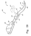
- FIGS. 2 to 6 show the second plate member 116 in greater detail.
- the second plate member 116 is configured to permit the second plate member 116 to slideably move along the first connecting member 108 and the second connecting member 114. It should be appreciated that the second plate member 116 may have a construction that is typical for all plate members that are to be fitted onto the first connecting member 108 and the second connecting member 114 of the bone plate assembly 102 of FIG. 1 .
- FIG. 2 shows the second bone plate 116 with a first channel 120 and a second channel 122 which permit the sliding movement of the connecting of the second plate member 116 along the connecting members 120 and 122
- the second plate member 116 is shown in FIGS. 2 to 6 to have two configurations. In a first configuration the plate member 116 may slide along the connecting members. In a second configuration the plate member 116 is fixedly secured to the connecting members. To provide the two arrangements, the second plate member 116 may be constructed of two components.
- the second plate member 116 includes a lower plate portion 126 and an upper plate portion 128.
- the upper plate portion 128 is permitted to move slightly with respect to the lower plate portion 126 such that the connecting members 108 and 114 may slide along the channels 120 and 122.
- the upper plate portion 128 is secured to the lower plate portion 126 by, for example, a first plate rivet 130 and a spaced apart second plate rivet 132.
- the first plate rivet 130 is fitted into first rivet opening 134 while the second plate rivet 132 is fitted into second rivet opening 136.
- the openings 134 and 136 are formed in the lower plate portion 126 and in the upper plate portion 128 of the second plate member 116.
- the second plate member 116 may include a plate fastener opening 138 for receiving bone screw 140 for securing the second plate member 116 to bone 2.
- the opening 138 is formed in the lower plate portion 126 and in the upper plate portion 128 of the second plate member 116.
- the bone screw 140 may be in the form of a cancellous screw or a cortical screw.
- FIGS. 3 to 6 show the second plate member 116 with the first channel 120 defining a channel height CH.
- the upper plate portion 128 and the lower plate portion 126 define a space or gap having a gap width GW.
- the first connecting member 108 defines a connecting member diameter CD. It should be appreciated that if the connecting member diameter CD of the connecting member 108 has a dimension larger than the channel height CH when the lower plate portion 126 and the upper plate portion 128 are urged into contact in second configuration, the upper plate portion 128 and lower plate portion 126 will squeeze or hold the connecting member 108 in the channel 120.
- the gap width GW and the channel height CH are greater than the connecting member diameter CD of the connecting member 108.
- the second plate member 116 is able to move in the direction 118 along the connecting members 108 and 114.
- FIGS. 5 and 6 show the second plate member 116 with a fastener opening 138.
- the fastener opening 138 cooperates with the fastener 140 to cause the upper plate portion 128 to move toward lower plate portion 126 to fixedly secure the second plate member 116 to the connecting members 108 and 114.
- the fastener opener 138 includes a counter bore 142 that matingly fits and holds head 144 of the bone fastener 140.
- the fastener opener 138 further defines internal threads 146 formed in lower plate portion 126. The internal threads 146 mate with external threads 148 formed on bone fastener 140.
- the external threads 148 on the bone fastener 140 cooperate with internal threads 146 on the lower plate portion 128 of the second plate member 116 to draw the upper plate portion 128 against the lower plate portion 126 to secure the second plate member 116 to the connecting members 108 and 114.
- bone screw 140 with two threaded portions (not shown), in which a first threaded portion engages the bone and a second threaded portion engages internal threads 146 of second plate member 116.
- first threaded portion engages the bone
- second threaded portion engages internal threads 146 of second plate member 116.
- the type of thread of each threaded portion may be individually adapted to the desired application.
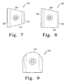
- FIGS. 7 to 13 show additional plate members for use with the bone plate assembly 100.
- a third plate member 150 includes channels and a bone screw opening similar to that of the second plate member 116.
- the third plate member 150 includes parallel opposed first sides 152 as well as a second side set of opposed sides 154 which are not parallel to one other.
- the bone plate assembly 102 may be configured to have a longitudinal axis that is not linear.
- FIG. 8 shows a fourth plate member which has a pair of channels and a bone screw opening similar to that of the second plate member 114, and includes a first set of parallel sides 158 as well as a third and fourth opposed set of sides 160 which are not parallel.
- FIG. 9 shows a fifth plate member which includes a side 164 which is curved or arcuate.
- the arcuate surface 164 may be used at the end of distal portion of the bone plate assembly 102.
- FIG. 10 shows a sixth plate member which 166 has a shape generally that of a parallelogram.
- FIG. 11 shows a seventh plate member which 168 is generally L-shaped and includes an opening 170 in a bone portion 172 that extends outwardly or beyond the channels 174 of the seventh plate member 168.
- FIG. 12 shows an eighth plate member which includes two spaced apart bone screw openings and is rectangular.
- FIG. 13 shows a ninth plate member 178 which includes opposed wings 180.
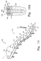
- FIG. 14 shows a completed bone plate assembly 102 in which the second plate member 116 abuts against first plate member 104 such that a minimal length of connectors 108 and 114 is exposed, allowing the rigidity of the assembly to be maximised.
- Another plate member such as the fourth plate member 156 shown in FIG. 8 , is positioned tightly against the second plate member 116.
- An additional plate member for example another second plate member 116, is positioned against fourth plate member 156.
- a tenth plate member 182 having a configuration which is a mirror image of that of a fourth plate member 156 may be positioned against second plate member 116.
- third plate member 150 may be positioned against the tenth plate member 180.
- fifth plate member 162 having the arcuate portion 164 may be positioned against third plate member 150.
- the seven plate members shown in FIG. 14 are urged against each other and the excess portions 183 of the first connector 108 and second connector 114 are preferably removed by, for example, a conventional surgical wire cutting tool (not shown) such that a unitary bone plate or a rigid bone plate assembly 102 is provided.
- FIG. 14A shows a poly-axial screw assembly 140A which can be used as a substitute to bone screw 140 or may be used in addition to bone screw 140.
- a single assembly 140A may be used or a plurality of assemblies 140A may be positioned as desired on the plate assembly 102.
- the assembly 140A includes a bushing 137A with a spherical periphery 138A that swivels in a spherical pocket 139A formed in plate member 104A.
- the bushing 137A is split and expands to lock screw 142A into any one chosen of a multitude of angles by a tapered threaded head 141A on screw 142A with engages tapered threads 143A formed in hole 145A in bushing 137A.
- Suitable poly-axial bushings are disclosed in US-5954722 and in US-A-2005/0049594 .
- FIGS. 15 and 16 show the bone plate assembly 102. It is shown in FIG. 15 in a first configuration 184 in which adjacent bone plate members are spaced from each other in this configuration the bone plate may be conformed to the shape of the bone.
- the first configuration 184 may have the necessary rigidity to form a stable, fixation construct on the fractured bone, although the rigidity of bone plate assembly 102 as shown in FIG. 15 depends largely on the material and design of connectors 108 and 114.
- FIG. 16 shows the bone plate assembly 102 in a second configuration 186. In the second configuration 186, adjacent plate members are positioned in abutment or close proximity to each other such that the individual bone plates together with the connection members provide for a rigid construction to support the bone.
- FIG 16A illustrates the use of alternative fasteners instead of the bone screw 140 shown in FIG. 6A .
- the bone screw 140 may be substituted by poly-axial cancellous bone screw assembly 140B, by poly-axial bone pin assembly 140C, by locked bone pin 140D, by locked cortical bone screw 140E, by locked cancellous bone screw 140F, by un-locked cortical bone screw 140G, by un-locked cancellous bone screw 140H.
- Small holes may be placed in the bone plate 104 of FIG 1 to receive, for example, guide pins, for example, guide pin 140J.
- FIG 16B shows the bone plate 104 of FIG. 1 with a bushing which can be placed in the opening of the plate 104 to receive drills and reamers to prepare the holes for receiving the bone screws and the bone pins.
- a bushing 151A may be threadably engaged by threads 153A to bone plate 104B to guide a drill (not shown). Details of a suitable guide bushing are disclosed in US-A-2006/0149250 .
- FIG. 17 shows a bone plate assembly kit 101 from which components may be selected for assembling the bone plate assembly 100 of FIG. 1 .
- the kit 101 includes a tray 188 similar to those known in the art for organizing orthopaedic devices to be used in a specific surgical procedure. Tray 188 and its components may be constructed of materials that can withstand many cycles of steam autoclave sterilization.
- the kit 101 may include the first plate member 104. It should be appreciated that a plurality for example two first plate members 104 may be included in the kit 101. It should also be appreciated that the additional plate members, for example second plate member 116, may be included in the kit 101 and, for example, a plurality, for example, two second plate members 116 may be included in the kit 101. Similarly the kit 101 may include one or more third plate members 150, fourth plate members 156, fifth plate members 162, sixth plate members 166, seventh plate members 178, eighth plate members 176, as well as, ninth plate members 178. It should be appreciated that tenth plate member 182 may also be included in the kit, as well as additional plate members, for example plate members 179 and 181. It should be appreciated as shown in FIG.
- first connector member 108 and second connecting member 114 may be of sufficient length to accommodate the longest possible bone plate assembly that reasonably may be needed by the surgeon to perform trauma surgery.
- the kit 101 may also include bone screws 140 for use with the plate members. It should be appreciated that the bone screws 140 may all be of the type of FIG 6A and may be of varying lengths and sizes to accommodate different bones and different portions of bone. Further it should be appreciated that the bone screws may be of other types such as those shown in FIG. 16A .
- bone plate assembly 100 of FIGS. 1 to 17 is well suited for bone plates where the bone contact surface of bone 2 is generally planar, it should be appreciated that bone plates to accommodate bones which are non-planar or which cover a plurality of planes is desired. Such bones may include the shaft and condylar portions of long bones and bones with irregular shapes, for example bones associated with the pelvis.
- a bone plate assembly 200 is used to prepare a bone plate assembly 202 which provides for bone contact surfaces on a plurality of planes.
- FIG. 18 shows a bone plate assembly 200 which uses components from the kit 101.
- the bone plate assembly 200 may include first plate member 104 from the kit 101.
- the first plate member 104 includes the first connecting member 108 as well as the spaced apart second connecting member 114.
- Additional bone plate members may be assembled in sequence onto the connecting members 108 and 114 by feeding the connecting members 108 and 114 through the channels formed in the plate members.
- connecting members 108 and 114 are formed from a malleable material, they may pressed against the bone surface and hand-shaped to match the contours of the bone surface, then removed from the bone surface so that the plate members may easily be slid onto them in the proper sequence.
- the loose assembly may then be positioned on the bone surface and attached to the bone with the bone screws. As each bone screw is tightened, the respective plate member clamps tightly on to the connectors to stiffen that portion of the bone plate assembly.
- the second bone plate 116 may be positioned adjacent first plate member 104.
- the bone plate assembly 200 of FIGS. 18 and 19 is utilized by positioning the first connecting member 108 and the second connecting member 114 along the bone 2.
- the malleable connecting members 108 and 114 are positioned adjacent to bone such that when the plate member 114 is assembled onto the connecting members 108 and 114, the plate member closely conforms to the bone.
- the bone plate assembly 200 as shown in FIG. 18 includes a first non-planar plate member 290 which includes first and second parallel faces 292 as well as non-parallel faces 294.
- the first non-planar plate member 290 is positioned against second plate member 116.
- a second non-planar plate member 296 is positioned adjacent the first non-planer plate member 290.
- An additional second plate member 116 is positioned adjacent the second non-planar plate member 296.
- An additional second non-planar plate member 296 is positioned adjacent the second place member 116.
- a second first non-linear plate member 290 is positioned adjacent the second non-planar plate member 296.
- a fifth planer member 162 is positioned adjacent the first non-planar plate member 292 for the plate assembly 202 of FIG. 18 .
- the additional portions 183 of the first connecting member 108 and the second connecting member 114 are removed by for example a surgical wire cutting tool which trims off the excess of the flexible member that extends beyond the plate member 162.
- the plate member 296 includes a bone fastener opening 238 for receiving for example bone fastener 140.
- the plate member 296 further includes first rivet opening 234 that receives first rivet 230, as well as second rivet opening 236 that receives second rivet 232.
- the plate member 296 further includes first channel 220, as well as spaced apart second channel 222.
- the plate member 296 further includes first and second parallel sides 252, as well as non-parallel sides 254.
- the non-parallel sides 254 include a side 255 which is not perpendicular with bone contact surface 206 of the plate member 296.
- the plate assembly 202 of the bone plate assembly 200 of FIGS. 18 and 19 and the bone plate assembly 100 of FIGS. 1 to 17 may be suitable for many bone fractures, for those situations in which the area in both the X direction and Y direction for the fracture is large a bone plate may be necessary with greater width and yet, considerable length. Such a situation may occur in a fracture of the pelvis.
- FIGS. 20 to 25 show a bone plate assembly 300 which can provide three-dimensional fixation of a fracture on a broad, contoured surface of a bone such as the ilium.
- FIG. 20 shows a bone plate assembly 300 which includes a first bone plate 301 a second bone plate 303, and a third bone plate 305 connected to the second bone plate 303.
- the kit also includes a fourth bone plate 307 connected to the first bone plate 301, a fifth bone plate 309 connected to the fourth bone plate 307, a sixth bone plate 311 connected to the fifth bone plate 309, and a seventh bone plate 313 connected to the sixth bone plate 311.
- the bone plate assembly 300 may include an eighth bone plate 315 connected to the first bone plate 301, a ninth bone plate 317 connected to the eighth bone plate 315, a tenth bone plate 319 connected to the ninth bone plate 317 and an eleventh bone plate 321 connected to the tenth bone plate 319.
- the bone plate assembly 300 may further include a twelfth bone plate 323 connected to the first bone plate 301 and a thirteenth bone plate 325 connected to the third bone plate 305.
- the bone plate assembly 300 may further include a fourteenth bone plate 327 connected to the twelfth bone plate 323, a fifteenth bone plate 329 connected to the fourteenth bone plate 327 and a sixteenth bone plate 331 connected both to the thirteenth bone plate 325 and the fifteenth bone plate 329.
- the bone plate assembly 300 may further include a seventeenth bone plate 333 connected to the fourteenth bone plate 327. While the bone plate assembly 300 may be made, as shown in FIG. 20 , of planar plate members, it should be appreciated that non-planar members, such as the plate member 296 of FIG. 19 , may be used with the bone plate assembly 300.
- FIG. 21 shows a the plate assembly 302 attached to an ilium 8 of a patient.
- the plate assembly 302 can follow a plurality of planes to conform to the contour of the ilium 8 or other broad bone surfaces.
- the bone plate assembly 300 may include components of the bone plate assembly 200 and the bone plate assembly 100.
- the bone plate assembly 300 may for example include bone screws 140 as well as rectangular bone plates 116.
- the bone plate assembly 300 includes bone plates to provide for connection of bone plates both in a line and in a second line normal to the first line to form a grid of bone plates.
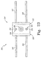
- the bone plate assembly 300 may include an X type bone plate 341.
- the bone plate member 341, as shown in FIGS. 22 and 23 includes first channel 320, as well as spaced apart second channel 322.
- the plate member 341 may further include a first connector 343 which extends from plate member 341.
- the plate member 341 may further include a second connector 345 spaced from and parallel to the first connector 343.
- the first connector 343 and second connector 345 are perpendicular to the first channel 320 and the second channel 322 to form a rectangular grid for the assembling of plate members.
- the plate member 341 may further include a third connector 347 extending from the plate member 341 in a direction opposed to first connector 343.
- the plate member 341 may further include a fourth connector 349 extending from the plate member 341 in a direction opposed to the second connector 345.
- the plate member 34 similarly to the plate member 160 of FIG. 2 , may include a first rivet 330 and a spaced apart second rivet 332.
- the first rivet 330 fits into first rivet opening 334 while the second rivet 332 fits into second rivet opening 336.
- the plate number 342 further includes a fastener opening 338 for use with plate fastener 140.
- FIG. 24 shows a T shaped plate member 351 for use with the bone plate assembly 300, which includes a first channel 353 and a spaced apart second channel 355.
- the plate member 351 further includes a first connector 357 positioned perpendicular to first channel 353 and a second connector 359 extending from the plate member 351 in a direction parallel to first connector 357.
- the T shaped plate member 351 further includes a bone fastener opening 361 for receiving the bone screw 140.
- FIG. 24A shows the bone plate assembly 300 with solitary connectors 363 for use with the bone plate assembly 300.
- the plate assembly 302 may be assembled in various orders.
- the third plate member 305 which may be in the form of T shaped plate member 351 as shown in FIG. 24 , is utilized.
- the second plate member 303 which may be in the form of plate member 116 of FIG. 2 is assembled against third plate member 305 by inserting the first connector 357 and the second connector 359 of the first plate member 305 into the channels in the second plate member 303.
- the first plate member 301 is connected to the second plate member 303.
- the first plate member 301 may be in the form of an X plate member 341, as shown in FIG. 22 .
- the first plate member 301 is assembled to the second plate member 303 by inserting the first connector 357 and the second connector 359 into the channel 320 and 322 of the X plate member 301.
- the fourth plate member 307 which may be in the form of 116 of FIG. 2 , is assembled against first plate member 301 by positioning the first connector 357 and the second connector 359 into the channels of the fourth plate member 347.
- the fifth plate member 309 which may be in the form of plate member 156 of FIG. 8 , is positioned in fourth plate member 307.
- the first connector 357 and the second connector 359 are inserted into channels formed in fifth plate member 309.
- the sixth plate member 311 is secured against fifth plate member 309.
- the sixth plate member 311 may be in the form of plate member 150 of FIG. 7 .
- the sixth plate member 311 is secured to the fifth plate member 309 by positioning the first connector 357 and the second connector 359 into the channels formed in the sixth bone plate 311.
- the eighth bone plate 315 is secured to the first bone plate 301.
- the eighth bone plate 315 may be in the form of bone plate 116 of FIG. 2 .
- the bone plate 315 is secured to the first bone plate 311 by inserting the first connector 343 and the second connector 345 into channels formed in the bone plate 315.
- the ninth bone plate 317 is secured to the eighth bone plate 315.
- the ninth bone plate 317 may be in the form of T plate member 351 as shown in FIG. 24 .
- the ninth bone plate 317 is secured to the eighth bone plate 315 by inserting the first connector 343 and the second connector 345 into the channels formed in the bone plate 300 ninth bone plate 317.
- the tenth bone plate 319 is secured to the ninth bone plate 317.
- the tenth bone plate 319 may be in the form of bone plate 316 of FIG. 2 .
- the tenth bone plate 319 is secured to the ninth bone plate 317 by inserting the first connector 357 and the second connector 359 into the channels formed in the tenth bone plate 319.
- the 11th bone plate 321 which may be in the form of plate 116 of FIG. 2 is secured to the tenth bone plate 319 by inserting the first connector 357 and the second connector 369 into cavities into channels formed in 11th bone plate 321.
- the twelfth bone plate is secured to the first bone plate 301.
- the twelfth bone plate 323 may be in the form of bone plate 116 of FIG. 2 .
- the twelfth bone plate 323 is secured to the first bone plate 311 by inserting the third connector 347 and the fourth connector 349 into channels formed in the twelfth bone plate 323.
- the fourteenth bone plate is connected to the fifteenth bone plate.
- the fourteenth bone plate 327 may be in the form of a T shaped bone plate 351 see FIG. 24 .
- the fifteenth bone plate 329 may be in the form of bone plate 116 of FIG. 2 .
- the fifteenth bone plate 329 is secured to the fourteenth bone plate 327 by inserting the first connector 343 and the second connector 345 into channels formed in fifteenth bone plate 329.
- the sixteenth bone plate 331 may then be secured to the fifteenth bone plate 329.
- the sixteenth bone plate 331 may be in the form of a T shaped plate member 351 as shown in FIG. 24 .
- the sixteenth bone plate 331 is connected to the fifteenth bone plate 329 by inserting first connector 343 and second connector 345 into channels formed in the sixteenth bone plate 331.
- the seventeenth bone plate 333 is connected to the fourteenth bone plate 327.
- the seventeenth bone plate 333 may be in the form of bone plate 116 as shown in FIG. 2 .
- the seventeenth bone plate 333 is connected to the fourteenth bone plate 327 by inserting third connector 347 and fourth connector 349 into channels formed in seventeenth bone plate 333.
- the thirteenth bone plate is next connected to the sixteenth bone plate 331.
- the thirteenth bone plate 325 may be in the form of bone plate 116 of FIG. 2 .
- the thirteenth bone plate 325 is secured to the sixteenth bone plate 116 by inserting fifth first connector 357 and second connector 359 into channels formed in thirteenth bone plate 325.
- the assembly of the 13th, 14 th, 15 th, 16 th, and 17 th bone plates is inserted into the assembly of the remaining bone plates by inserting the first connector 357 and the second connector 359 into channels formed in third bone plate member 305 and inserting connectors 347 and 349 into channels formed in fourteenth bone plate 327.
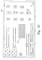
- FIG. 25 shows a kit 301 including a tray 388 containing all the components that may be used for bone assembly 300.
- kit 301 may be customized to provide the necessary components for specific types or classes of bone fracture repairs, and may be constructed of materials suitable for steam autoclave sterilization.
- the kit 301 may also include bone screws 140 for use with the plate members. It should be appreciated that the bone screws 140 may all be of the type of FIG. 6A and may be of varying lengths and sizes to accommodate different bones and different portions of bone. Further it should be appreciated that the bone screws may be of other types such as those shown in FIG. 16A .
- FIG. 26 shows a bone plate assembly 402 which includes a first plate member 404 to which a flexible track 405 is secured.
- the flexible track 405 extends outwardly from end 410 of the first plate member 404.
- the flexible track 405 includes a first connecter 408 and a second spaced apart connector 414.
- the first connector 408 and the second connector 414 are contained by a webbed retainer 407.
- the webbed retainer 407 and the first connector 408 and second connector 414 form the flexible track 405.
- the webbed retainer 407 may be formed from an implantable polymer that can withstand repeated cycles of a steam autoclave.
- the webbed retainer 407 encapsulates the first connecting first connector 408 and the second connector 414.
- the retainer 407 may encapsulate the first connector 408 and the second connector 414 by, for example, an extruding process.
- the first connector 408 and the second connector 414 may be heat-welded between layers of a polymeric film or between opposite sides of a flattened, thin wall, polymeric tube.
- the webbed retainer 407 loosely encapsulates connectors 408, 414 to permit sliding movement of the flexible members comprising each of the connectors, as in the previous embodiments, until clamped between the plate members.
- webbed retainer 407 may be sufficiently thin, for example in the range of 0.1 to 0.5 mm, to allow a desired flexibility of flexible track 405 and to allow easy penetration by self-tapping bone screws when attached to the fractured bone.
- webbed retainer 407 may have a lubricating surface to facilitate assembly and adjustment of the plate members.
- the bone plate assembly 400 includes a second plate member 416 that is slideably fitted along the flexible track 405.
- the second plate member 406 includes a first channel 420 and a spaced apart second channel 422 which receive the first connector 408 and second connector 414 respectively.
- the second plate member 416 includes a transverse opening 438 for receiving bone screw 440.
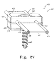
- FIG. 27 shows the second plate member 416 with an upper plate portion 426 and a second lower plate portion 428.
- the upper plate portion 426 and lower plate portion 428 define a gap 427 between each other.
- the gap between the upper plate portion 427 and the lower plate portion 428 may be accomplished by rivets, similar to those shown in FIGS. 2 to 6 .
- the upper plate portion 426 and lower plate portion 428 may be attached together by a bridge 429.
- plate member 416 may be assembled to the webbed flexible retainer member assembly in a "clip-on" fashion.
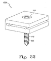
- FIG. 32 is an isometric view of plate member 416 with a bone screw fully inserted there through. It should be noted that the screw should not be inserted into plate member 416 while assembling to the flexible track 405.
- the second plate member 416 may be installed in a direction generally transverse to the longitudinal axis of track 405, that is by advancing the plate member 416 from first position 427 as shown in phantom to second position 429 as shown in solid.
- the assembly of the plate members may be more readily performed particularly in less invasive procedures.
- each assembled plate member may be removed from track 405 without requiring removal of adjacent plate members. It is possible, therefore, for the surgeon to easily modify the bone plate assembly 400 during the fracture repair procedure.
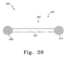
- FIG. 28 shows the flexible track 405, showing the first connector 408 and the second connector 414 encapsulated by the retainer 407.
- each of connectors 408 and 414 may include a grouping of a plurality of flexible members 409, 415 respectively, in any one of a number of possible arrangements.
- the flexible members may be formed, for example, from metallic wire or polymeric filaments and arranged in a circular grouping as shown in FIG. 28 . Relative longitudinal movement among the flexible members permits flexibility of connectors 408, 414. When the plate members are tightly clamped around connectors 408, 414 to prohibit such relative longitudinal movement, the flexible track 405 becomes sufficiently rigid to provide fixation of the fractured bone.
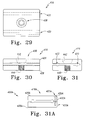
- FIGS. 29 to 31 show the second plate member 416, showing the first channel and the spaced apart second channel.
- An opening 438 is formed in the upper plate portion 426 and the lower plate portion 428 to permit the locking screw bone screw 440 to pass through it.
- a counter bore 442 for receiving the head of the bone screw 440 is formed in upper plate portion 426 of the second plate member 416.
- each plate member 416 it is also possible to provide each plate member 416, as for all the previous embodiments of the plate member, without any threaded holes. It would then be necessary to tighten the bone screw until the plate member compresses tightly against the bone surface so that the plate member clamps onto the connectors with sufficient force to stiffen the bone plate assembly. This arrangement may be preferred in the repair of fractures in healthy bone but perhaps not in osteoporotic bone in which screw engagement in the weak bone tissue is not optimal.
- a method for performing trauma surgery includes obtaining a 3D image of fractured bone, converting a 3D image into CAD model of fractured bone, inputting CAD model of the image into rapid prototype machine for example an SLA machine.
- the method 1100 further includes making a 3D physical model of the fractured bone, providing a bone fixation device, assembling the trial bone fixation device that conforms to a 3D physical model of the fractured bone and assembling the implantable bone fixation device having the same configuration as the trial device.
- the method includes providing a kit including a tray for storing a plurality of plate members and at least one connection member. At least two of the plate members have different shapes.
- the method further includes selecting at least one plate member from the plurality of plate members and at least one connection member from the plurality of connection members, assembling the selected at least one plate member to the selected one connecting member placing the assembled plate and connection member against the damaged bone and locking the plate to the connection member.
Abstract
Description
- This application relates generally to the field of orthopaedics, and more specifically to bone plates and systems for stabilization and compression of fractured or otherwise damaged bones.
- Bone plates for internal fixation of fractured bones should generally conform to the contours of the fractured bone surface. This is especially true for compression plates that are screwed tightly against the bone. Matching the plate shape to the bone contours is important with compression plates in order to allow proper distribution of loads between the bone and the plate during healing of the fracture. It is also desirable for the plate to have a low profile and to blend with the bone surface as much as possible so as not to irritate or interfere with surrounding soft tissues, nerves, tendons, vessels, etc.
- One type of bone plate for acetabular and other pelvic fractures is called a reconstruction bar. Conventional reconstruction bars are generally formed from a biocompatible metal that may be bent by the surgeon using special tools in order to configure the bar to conform to the bone. Typically the surgeon first forms a thin metal template by hand to conform to the bone surface at the fracture site. Working through an open incision, the surgeon bends the template to approximate the desired shape, places the template against the bone surface, removes the template, adjusts the shape of the template and repeats these steps until the template closely matches the shape of the bone surface. Then the surgeon, sometimes with the help of an assistant, uses a number of special forming tools to bend the reconstruction bar to be implanted into approximately the same configuration as the template, visually holding the bar and template side-by-side to assess when the bar is adequately similar to the template. This procedure may take several minutes of time and a significant amount of skill. The bar may then be attached to the bone using conventional cortical screws. It is not likely that the bar shape exactly matches the bone surface shape, so tightening of the bone screws may draw the bar against the bone surface, thereby inducing bending preloads at various locations along the bar due to the spring-back characteristic of the bar material. Alternatively, the bar may be implanted with significant gaps between various locations of the bar and the bone surface, resulting in the uneven transfer of loads between the bone and bar construct. Therefore, it would be advantageous to provide a reconstruction bar that may be implanted more quickly by the surgeon, requires fewer ancillary tools, is more conformable and contoured to the bone surface and is at least as effective as a fixation device compared to conventional reconstruction bars.
- Another issue currently faced by orthopaedic device manufacturers is the need to provide a full line of bone plates for a large variety of bone fractures and patient anatomies. The manufacturing costs associated with forming each rigid, one-piece bone plate is significant due largely to the need to configure the plate to approximately match the bone surface shape. Furthermore, a large product inventory must be provided to the user (hospitals) to be prepared for the many types of fractures and patient anatomies to be treated. Accordingly, it would be advantageous to provide bone plates that have broader indications, where each plate may be suitable for a larger variety of fractures and patient anatomies than currently available plates. Potentially, such bone plates may be produced at lower costs than current plates and inventories reduced without compromising surgical outcomes.
- What is also needed is a bone fixation device and method of the kind discussed above which can be implanted quickly, requires fewer ancillary tools, and is at least as effective as a fixation device compared to conventional fixation devices, which can be configured to conform to a broad, contoured bone surface. The fixation device may, for example, reduce the need to use multiple bone plates for particular types of fractures, including comminuted acetabular fractures (see Chapter 20 of Orthopaedic Surgery Essentials: TRAUMA, published by Lippincott Williams and Wilkins, 2006).
- There is also a need to provide surgeons with devices and methods to create custom, bone fixation devices intraoperatively for less common types of bone fractures, and generally to provide recourse in cases in which conventional bone plates are unavailable.
- In one aspect, the present invention provides a kit for the construction of a bone plate assembly for fixation of a fractured bone, which includes a plurality of plate members, a connecting member for retaining the plurality of plate members in a desired configuration, and a plurality of locking members for securing the plate members to the connecting member.
- Preferably, the plurality of plate members include at least two plate members.
- Preferably, the locking members are bone screws. Each plate member includes at least one opening for retaining one of the bone screws such that the bone screws may securely attach the bone plate assembly to the fractured bone.
- Preferably, the connecting member is flexible.
- Preferably, the connecting member securely retains the plurality of plate members in a first arrangement in which each of the plurality of plate members can be moved with respect to each other such that the bone plate assembly generally conforms to the surface of the fractured bone, and in which the locking member may fixedly secure the plate members to the connecting member in a second arrangement such that the bone plate assembly is sufficiently rigid to provide fixation of the fractured bone.
- Preferably, the connecting member includes a plurality of flexible members. In the first arrangement the plurality of plate members are loosely retained on the connectors such that the flexible members may move longitudinally relative to each other, and in the second arrangement plate members are clamped tightly onto the connectors such that the flexible members are not permitted to move substantially relative to each other.
- Preferably, each of the plurality of plate members includes a groove for receiving the connecting member.
- Preferably, the plate members define a bone contacting surface and the connecting member defines a longitudinal axis of the member. The plate members also define a first dimension perpendicular to the bone contact surface and the longitudinal axis, and a second dimension parallel to the bone contact surface and the normal to the longitudinal axis, the first dimension is greater that the second dimension.
- Preferably, the first dimension is at least twice as large as the second dimension.
- Preferably, the connecting member includes a first portion, a second portion spaced from the first portion and a retainer to retain the first portion and the second portion in a spaced apart relationship.
- Preferably, a first of the plurality of plate members defines a surface thereof, a second of the plurality of plate members defines a surface for contact with the surface of the first plate member, and the surface of the first plate member and the surface of the second plate member provide planar contact with each other.
- Preferably, the plurality of plate members include a first plate member having a first shape and a second plate member having a second shape, the second shape is different than the first shape.
- Preferably, the plurality of plate members include a first plate member and a second plate member, the first plate member defines a first bone contacting surface and the second plate member defines a second bone contacting surface. The first bone contacting surface and the second bone contacting surface lie in different planes.
- Preferably, the kit includes a second connecting member for securing the plurality of plate members to each other. The second connecting member is spaced from the first mentioned connecting member.
- Preferably, the kit includes a tray for containing the plurality of plate members, the locking members and the connecting member prior to use.
- Preferably, the plurality of plate members include a first plate member and a second plate member which can be positioned adjacent to the first plate member. The first plate member and the second plate member define a longitudinal axis of the plate members. The plurality of plate members also include a third plate member adjacent the first plate member and extending from the first plate member in a direction skewed with respect to the longitudinal axis of the first plate member and the second plate member.
- Preferably, the kit includes a fourth plate member adjacent the first plate member and extending from the first plate member in a direction skewed with respect to the longitudinal axis of the first plate member and the second plate member.
- In another aspect, the invention provides a kit for use in trauma surgery for cooperation with a bone, which includes a first plate member having a first shape and a second plate member having a second shape. The kit also includes a connecting member for securing the plurality of plate members to each other. The second shape is different than the first shape.
- Preferably, the first plate member defines a first bone contacting surface and the second plate member defines a second bone contacting surface. The first bone contacting surface and the second bone contacting surface lie in different planes.
- Preferably, the connecting member may be fixedly secured to the plurality of plate members in a first arrangement in which each of the plurality of plate members can be moved with respect to each other and in a second arrangement in which each of the plurality of plate members is rigidly secured to each other.
- In a further aspect, the invention provides a kit for the construction of a bone plate assembly for fixation of a fractured bone is provided. The kit includes a plurality of plate members and a flexible track for retaining the plurality of plate members in a desired configuration. The kit also includes a plurality of locking members for securing the plate members to the connecting member.
- Preferably, kit, the track includes a flexible retainer containing a grouping of a plurality of flexible members. The track has at least one free end.
- Preferably, the flexible members are formed from a malleable material, such that a surgeon may shape the track into an implant configuration to conform to the fractured bone surface. Each of the plurality of plate members may be assembled to the flexible track while the flexible track is in the implant configuration.
- The kits of the invention can be used in a method of stabilizing a damaged bone, which includes the steps of providing a kit of including a tray for storing a plurality of plate members and at least one connection, at least two of the plate members having different shapes and selecting at least one plate member from the plurality of plate members and at least one connection member from the plurality of connection members. The method also includes the steps of assembling the selected at lease one plate member to the selected one connection member, placing the assembled plate and connection member against the damaged bone, and locking the plate to the connection member.
- The kit of the invention can facilitate the shaping of a plate without bending tools to match contours of broad bone surfaces such as on the pelvis, thereby improving fixation and reducing surgical procedure time
- The kit of the invention can help to minimise bone plate manufacturing costs and required inventory
- The kit of the invention can facilitate the provision of a wide variety of custom plates intraoperatively for less common fractures or for when conventional bone plates are not available.
- The kit of the invention can facilitate a reduction in the number of bone plates that is required for certain types of comminuted fractures.
- Embodiments of the invention will now be described by way of example with reference to the accompanying drawings, in which:
-
FIG. 1 is an isometric view of a portion of a bone plate assembly for repairing bone fractures including a first plate member to which a pair of spaced apart connectors are secured, a second plate member fitted to the connectors and a bone screw; -
FIG. 2 is a an isometric view of the second plate member ofFIG. 1 showing rivets for securing the two portions of the second plate member together; -
FIG. 3 is an end view of the second plate member ofFIG. 2 ; -
FIG. 4 is a top view of the second plate member ofFIG. 2 ; -
FIG. 5 is a cross sectional view ofFIG. 4 along the line 5-5 in the direction of the arrows; -
FIG. 6 is a cross sectional view ofFIG. 4 along the line 6-6 in the direction of the arrows; -
FIG. 6A is a plan view of a fastener for use with the plate member ofFIG. 2 ; -
FIG. 7 is a top view of a four sided plate member with two opposed parallel sides and two opposed non parallel sides; -
FIG. 8 is a top view of a four sided plate member with two opposed parallel sides and two opposed non parallel sides; -
FIG. 9 is a top view of a four sided plate member with two opposed parallel sides, a third normal side and a fourth curved side; -
FIG. 10 is a top view of a four sided plate member with two opposed parallel sides and two opposed non parallel sides; -
FIG. 11 is a top view of an L-shaped plate member; -
FIG. 12 is a top view of a rectangular shaped plate member; -
FIG. 13 is a top view of a plate member with two opposed parallel sides and two opposed arcuate sides; -
FIG. 14 is a an isometric view of the bone plate assembly ofFIG. 1 assembled with several plate members and shown with several bone screws inserted into the plate members; -
FIG. 14A is a cross sectional view of a poly-axial bone screw that may be used with the bone plate assembly ofFIG. 1 ; -
FIG. 15 is a partial top view of the bone plate assembly ofFIG. 14 with the plate members in a slightly spaced apart relationship to show a flexible plate assembly; -
FIG. 16 is a partial top view of the plate assembly ofFIG. 14 with the plate members in a touching relationship to show a rigid plate assembly; -
FIG. 16A is a plan view of alternate bone screws and pins that may be used with the bone plate assembly ofFIG. 1 ; -
FIG 16B is a plan view of a bushing that may be used with the bone plate assembly ofFIG. 1 ; -
FIG. 17 is a top view of the plate kit ofFIG. 1 disassembled with several plate members to form a plate kit with the kit components placed in a sterilization tray; -
FIG. 18 is a an isometric view of a bone plate assembly according to another embodiment of the present invention including components of the kit ofFIG. 1 as well as additional components for use on a non-planar bone surface; -
FIG. 19 is an isometric view of a plate member for use with the bone plate assembly ofFIG. 18 for use on a non-planar bone surface; -
FIG. 20 is a an isometric view of a bone plate assembly according to another embodiment of the present invention including components of the kit ofFIG. 17 as well as additional components for use on large bone surfaces; -
FIG. 21 is a an isometric view of the bone plate assembly ofFIG. 20 attached to the surface of the ilium for repair of an acetabular fracture; -
FIG. 22 is an isometric view of a plate member for use with the bone plate assembly ofFIG. 20 for use on large bone surfaces; -
FIG 23 is a top view of the plate member ofFIG. 22 ; -
FIG. 24 is an top view of another plate member for use with the bone plate assembly of FIG. for use on large bone surfaces; -
FIG. 24A is a plan view of a connector for use with the bone plate assembly ofFIG. 20 . -
FIG. 25 is a top view of a kit including a sterilization tray containing several plate members that may be assembled into a plurality of alternate embodiments of a bone plate assembly such as the bone plate assembly shown inFIG. 18 ; -
FIG. 26 is an isometric view of a bone plate assembly including a first plate member attached to a flexible track having a pair of spaced apart connectors, a second plate member fitted to the flexible track according to another embodiment of the present invention; -
FIG. 27 is an isometric view of the second plate member ofFIG. 26 showing a bone screw inserted through the second plate member and flexible track; -
FIG. 28 is an end view of the flexible track ofFIG. 27 ; -
FIG. 29 is a top view of another embodiment of second plate member that may be assembled to the track ofFIG. 28 ; -
FIG. 30 is a side view of the second plate member ofFIG. 29 ; -
FIG. 31 is a end view of the second plate member ofFIG. 29 ; -
FIG. 31A is a end view of an alternate version of the second plate member shown inFIG. 31 ; and -
FIG. 32 is an isometric view of the second plate member ofFIG. 29 including a fully inserted bone screw. - Referring to the drawings,
FIG. 1 shows abone plate assembly 100 which can be used in trauma surgery for cooperation with a bone. For example, thebone plate assembly 100 may be utilized to formbone plate assembly 102. - The
bone plate assembly 100 includes afirst plate member 104. Thefirst plate member 104 may have been a suitable shape and may as shown inFIG. 1 , have a shape suitable for contact with a condylar portion of abone 2. For example, thefirst plate member 104 may have a generally truncated triangular shape such that thecontact surface 106 of theplate member 104 may conform to a condylar portion of a bone. - The
bone plate assembly 100 may further include a connectingmember 108 for securing the plate members to each other. For example, as shown inFIG. 1 , a first connectingmember 108 may extend fromend 110 of thefirst plate member 104. The first connectingmember 108 may be secured to thefirst plate member 104 in any suitable fashion. For example, the first connectingmember 108 may be interferencely fitted intoopening 112 formed infirst plate member 104. Alternatively, the first connectingmember 108 may be welded or threadably attached to thefirst plate member 104. - Plate member, for example the
first plate member 104 may be made of any suitable durable material. For example, thefirst plate member 104 may be made of a durable plastic, a composite material or a metal. The material of which thefirst plate member 104 is made is preferably compatible with the human anatomy and if made of a metal, the material may be, for example made of a stainless steel alloy, a titanium alloy, or a cobalt chromium alloy. - The bone contacting surface 101 may be a planar surface. To better conform to bone, the
bone contact surface 106 may be arcuate and may be generally concave to mate with a generally convex periphery of, for example, a long bone. - The first connecting
member 108 may include, for example, a plurality of flexible elements that are formed, for example, from a biocompatible material such as 316L stainless steel, titanium, titanium alloy or any one of numerous polymers known in the art. The material of the flexible element may be malleable or spring-like. The flexible elements may be held together in a grouping such that the flexible elements may slide longitudinally relative to each other unless clamped tightly together bysecond plate member 116, whereby the clamped portion ofconnector 108 becomes relatively stiff. As described in the referenced patent application, the flexible elements may be clamped together to exhibit a beam stiffness that withstands a predetermined threshold force, thereby forming a suitably rigid construct for fixation of a fractured bone. -
FIG.1 illustrates the use of a solitary connectingmember 108. Thebone plate assembly 100 may further include the second connectingmember 114. The second connectingmember 114 is secured tofirst plate member 104. The second connectingmember 114 may be made of a similar material and may be of a similar size to that of the first connecting member. The second connectingmember 114 may be connected to end 110 of thefirst member 104 by, for example, aconnection 112 in the form of an interference fit, a threaded connection or by a weld. - As shown in
FIG. 1 , thebone plate assembly 100 includes asecond plate member 116. Thesecond plate member 116 may be made of any suitable durable material and may for example be made of a metal. If made of a metal, thesecond plate member 116 may be made of, for example, cobalt chromium alloy steel, a stainless steel alloy or titanium alloy steel. - As shown in
FIG.1 . the first connectingmember 108 and the second connectingmember 114 may be formed from a flexible material. By making the first connectingmember 108 and thesecond member 114 from a flexible material, the connectingmembers bone plate assembly 100 is to be used. If the first connectingmember 108 and second connectingmember 114 are formed from a malleable material, they may be shaped like a template to generally match the contour of the bone surface. If the connectingmembers bone plate assembly 100 may tend to lift away from the bone surface until all the bone screws are inserted and tightened. - It should be appreciated that the connecting
members members bone plate assembly 100 may include merely the connectingmembers first plate member 104 and thesecond plate member 116, it should be appreciated that additional plate members may be assembled onto the connectingmembers bone plate assembly 102 of any of numerous lengths and configurations. - The
second plate member 114 may be assembled on to the first connectingmembers 108 and the second connectingmembers 114 by advancing the second plate member in the direction ofarrow 118. For example, the first connectingmember 108 may be slideably fitted throughfirst channel 120 formed in the second plate member while similarly, the second connectingmember 114 may be slideably fitted throughsecond channel 122 formed in thesecond plate member 116. Thesecond plate member 116 is advanced in the direction ofarrow 118 until thesecond plate member 116 is advanced to second position or assembledposition 124 shown in phantom with thesecond plate member 116 in position againstend 110 of thefirst plate member 104. -
FIGS. 2 to 6 show thesecond plate member 116 in greater detail. Thesecond plate member 116 is configured to permit thesecond plate member 116 to slideably move along the first connectingmember 108 and the second connectingmember 114. It should be appreciated that thesecond plate member 116 may have a construction that is typical for all plate members that are to be fitted onto the first connectingmember 108 and the second connectingmember 114 of thebone plate assembly 102 ofFIG. 1 . -
FIG. 2 shows thesecond bone plate 116 with afirst channel 120 and asecond channel 122 which permit the sliding movement of the connecting of thesecond plate member 116 along the connectingmembers - The
second plate member 116 is shown inFIGS. 2 to 6 to have two configurations. In a first configuration theplate member 116 may slide along the connecting members. In a second configuration theplate member 116 is fixedly secured to the connecting members. To provide the two arrangements, thesecond plate member 116 may be constructed of two components. - For example, as shown in
FIG. 2 , thesecond plate member 116 includes alower plate portion 126 and anupper plate portion 128. In the first configuration, theupper plate portion 128 is permitted to move slightly with respect to thelower plate portion 126 such that the connectingmembers channels upper plate portion 128 is secured to thelower plate portion 126 by, for example, afirst plate rivet 130 and a spaced apartsecond plate rivet 132. Thefirst plate rivet 130 is fitted into first rivet opening 134 while thesecond plate rivet 132 is fitted into second rivet opening 136. Theopenings lower plate portion 126 and in theupper plate portion 128 of thesecond plate member 116. - The
second plate member 116 may include aplate fastener opening 138 for receivingbone screw 140 for securing thesecond plate member 116 tobone 2. Theopening 138 is formed in thelower plate portion 126 and in theupper plate portion 128 of thesecond plate member 116. Thebone screw 140 may be in the form of a cancellous screw or a cortical screw. -
FIGS. 3 to 6 show thesecond plate member 116 with thefirst channel 120 defining a channel height CH. Theupper plate portion 128 and thelower plate portion 126 define a space or gap having a gap width GW. The first connectingmember 108 defines a connecting member diameter CD. It should be appreciated that if the connecting member diameter CD of the connectingmember 108 has a dimension larger than the channel height CH when thelower plate portion 126 and theupper plate portion 128 are urged into contact in second configuration, theupper plate portion 128 andlower plate portion 126 will squeeze or hold the connectingmember 108 in thechannel 120. - Alternatively, when the
lower plate portion 126 and theupper plate portion 128 are spaced apart, the gap width GW and the channel height CH are greater than the connecting member diameter CD of the connectingmember 108. In this first configuration, thesecond plate member 116 is able to move in thedirection 118 along the connectingmembers -
FIGS. 5 and 6 show thesecond plate member 116 with afastener opening 138. Thefastener opening 138 cooperates with thefastener 140 to cause theupper plate portion 128 to move towardlower plate portion 126 to fixedly secure thesecond plate member 116 to the connectingmembers fastener opener 138 includes a counter bore 142 that matingly fits and holdshead 144 of thebone fastener 140. Thefastener opener 138 further definesinternal threads 146 formed inlower plate portion 126. Theinternal threads 146 mate withexternal threads 148 formed onbone fastener 140. As thebone fastener 140 is advanced through thefastener opening 138, theexternal threads 148 on thebone fastener 140 cooperate withinternal threads 146 on thelower plate portion 128 of thesecond plate member 116 to draw theupper plate portion 128 against thelower plate portion 126 to secure thesecond plate member 116 to the connectingmembers - It is also possible to provide
bone screw 140 with two threaded portions (not shown), in which a first threaded portion engages the bone and a second threaded portion engagesinternal threads 146 ofsecond plate member 116. With this arrangement, the type of thread of each threaded portion may be individually adapted to the desired application. -
FIGS. 7 to 13 show additional plate members for use with thebone plate assembly 100. For example athird plate member 150 includes channels and a bone screw opening similar to that of thesecond plate member 116. Thethird plate member 150 includes parallel opposedfirst sides 152 as well as a second side set ofopposed sides 154 which are not parallel to one other. By providing thethird plate member 150, thebone plate assembly 102 may be configured to have a longitudinal axis that is not linear. -
FIG. 8 shows a fourth plate member which has a pair of channels and a bone screw opening similar to that of thesecond plate member 114, and includes a first set ofparallel sides 158 as well as a third and fourth opposed set ofsides 160 which are not parallel. -
FIG. 9 shows a fifth plate member which includes aside 164 which is curved or arcuate. Thearcuate surface 164 may be used at the end of distal portion of thebone plate assembly 102. -
FIG. 10 shows a sixth plate member which 166 has a shape generally that of a parallelogram. -
FIG. 11 shows a seventh plate member which 168 is generally L-shaped and includes anopening 170 in abone portion 172 that extends outwardly or beyond thechannels 174 of theseventh plate member 168. -
FIG. 12 shows an eighth plate member which includes two spaced apart bone screw openings and is rectangular. -
FIG. 13 shows aninth plate member 178 which includes opposedwings 180. -
FIG. 14 shows a completedbone plate assembly 102 in which thesecond plate member 116 abuts againstfirst plate member 104 such that a minimal length ofconnectors fourth plate member 156 shown inFIG. 8 , is positioned tightly against thesecond plate member 116. An additional plate member, for example anothersecond plate member 116, is positioned againstfourth plate member 156. Atenth plate member 182 having a configuration which is a mirror image of that of afourth plate member 156 may be positioned againstsecond plate member 116. For examplethird plate member 150 may be positioned against thetenth plate member 180. Finally,fifth plate member 162 having thearcuate portion 164 may be positioned againstthird plate member 150. The seven plate members shown inFIG. 14 are urged against each other and theexcess portions 183 of thefirst connector 108 andsecond connector 114 are preferably removed by, for example, a conventional surgical wire cutting tool (not shown) such that a unitary bone plate or a rigidbone plate assembly 102 is provided. -
FIG. 14A shows a poly-axial screw assembly 140A which can be used as a substitute tobone screw 140 or may be used in addition tobone screw 140. A single assembly 140A may be used or a plurality of assemblies 140A may be positioned as desired on theplate assembly 102. The assembly 140A includes abushing 137A with aspherical periphery 138A that swivels in aspherical pocket 139A formed inplate member 104A. Thebushing 137A is split and expands to lockscrew 142A into any one chosen of a multitude of angles by a tapered threadedhead 141A onscrew 142A with engages taperedthreads 143A formed inhole 145A inbushing 137A. Suitable poly-axial bushings are disclosed inUS-5954722 and inUS-A-2005/0049594 . -
FIGS. 15 and 16 show thebone plate assembly 102. It is shown inFIG. 15 in afirst configuration 184 in which adjacent bone plate members are spaced from each other in this configuration the bone plate may be conformed to the shape of the bone. Thefirst configuration 184 may have the necessary rigidity to form a stable, fixation construct on the fractured bone, although the rigidity ofbone plate assembly 102 as shown inFIG. 15 depends largely on the material and design ofconnectors FIG. 16 shows thebone plate assembly 102 in asecond configuration 186. In thesecond configuration 186, adjacent plate members are positioned in abutment or close proximity to each other such that the individual bone plates together with the connection members provide for a rigid construction to support the bone. -
FIG 16A illustrates the use of alternative fasteners instead of thebone screw 140 shown inFIG. 6A . It should be appreciated that thebone screw 140 may be substituted by poly-axial cancellousbone screw assembly 140B, by poly-axialbone pin assembly 140C, by lockedbone pin 140D, by lockedcortical bone screw 140E, by lockedcancellous bone screw 140F, by un-lockedcortical bone screw 140G, by un-lockedcancellous bone screw 140H. Small holes may be placed in thebone plate 104 ofFIG 1 to receive, for example, guide pins, for example,guide pin 140J. -
FIG 16B shows thebone plate 104 ofFIG. 1 with a bushing which can be placed in the opening of theplate 104 to receive drills and reamers to prepare the holes for receiving the bone screws and the bone pins. For example abushing 151A may be threadably engaged bythreads 153A to bone plate 104B to guide a drill (not shown). Details of a suitable guide bushing are disclosed inUS-A-2006/0149250 . -
FIG. 17 shows a bone plate assembly kit 101 from which components may be selected for assembling thebone plate assembly 100 ofFIG. 1 . The kit 101 includes atray 188 similar to those known in the art for organizing orthopaedic devices to be used in a specific surgical procedure.Tray 188 and its components may be constructed of materials that can withstand many cycles of steam autoclave sterilization. - The kit 101 may include the
first plate member 104. It should be appreciated that a plurality for example twofirst plate members 104 may be included in the kit 101. It should also be appreciated that the additional plate members, for examplesecond plate member 116, may be included in the kit 101 and, for example, a plurality, for example, twosecond plate members 116 may be included in the kit 101. Similarly the kit 101 may include one or morethird plate members 150,fourth plate members 156,fifth plate members 162,sixth plate members 166,seventh plate members 178,eighth plate members 176, as well as,ninth plate members 178. It should be appreciated thattenth plate member 182 may also be included in the kit, as well as additional plate members, forexample plate members 179 and 181. It should be appreciated as shown inFIG. 17 , thatfirst connector member 108 and second connectingmember 114 may be of sufficient length to accommodate the longest possible bone plate assembly that reasonably may be needed by the surgeon to perform trauma surgery. The kit 101 may also include bone screws 140 for use with the plate members. It should be appreciated that the bone screws 140 may all be of the type ofFIG 6A and may be of varying lengths and sizes to accommodate different bones and different portions of bone. Further it should be appreciated that the bone screws may be of other types such as those shown inFIG. 16A . - While the
bone plate assembly 100 ofFIGS. 1 to 17 is well suited for bone plates where the bone contact surface ofbone 2 is generally planar, it should be appreciated that bone plates to accommodate bones which are non-planar or which cover a plurality of planes is desired. Such bones may include the shaft and condylar portions of long bones and bones with irregular shapes, for example bones associated with the pelvis. For example, and as shown inFIG. 18 and19 , abone plate assembly 200 is used to prepare abone plate assembly 202 which provides for bone contact surfaces on a plurality of planes. - For example,
FIG. 18 shows abone plate assembly 200 which uses components from the kit 101. For example, thebone plate assembly 200 may includefirst plate member 104 from the kit 101. Thefirst plate member 104 includes the first connectingmember 108 as well as the spaced apart second connectingmember 114. Additional bone plate members may be assembled in sequence onto the connectingmembers members members - As shown in
FIG. 18 , thesecond bone plate 116 may be positioned adjacentfirst plate member 104. Similarly as to theplate 102 of the kit 101 ofFIGS. 1 to 17 , thebone plate assembly 200 ofFIGS. 18 and19 is utilized by positioning the first connectingmember 108 and the second connectingmember 114 along thebone 2. The malleable connectingmembers plate member 114 is assembled onto the connectingmembers - The
bone plate assembly 200 as shown inFIG. 18 includes a firstnon-planar plate member 290 which includes first and second parallel faces 292 as well as non-parallel faces 294. The firstnon-planar plate member 290 is positioned againstsecond plate member 116. A secondnon-planar plate member 296 is positioned adjacent the firstnon-planer plate member 290. An additionalsecond plate member 116 is positioned adjacent the secondnon-planar plate member 296. An additional secondnon-planar plate member 296 is positioned adjacent thesecond place member 116. Similarly a second firstnon-linear plate member 290 is positioned adjacent the secondnon-planar plate member 296. Afifth planer member 162 is positioned adjacent the firstnon-planar plate member 292 for theplate assembly 202 ofFIG. 18 . - After the
fifth plate member 162 is positioned adjacent the firstnon-planar plate member 290, theadditional portions 183 of the first connectingmember 108 and the second connectingmember 114 are removed by for example a surgical wire cutting tool which trims off the excess of the flexible member that extends beyond theplate member 162. - Referring now to
FIG. 19 the second non-planar lockingplate member 296 is shown in greater detail. Theplate member 296 includes abone fastener opening 238 for receiving forexample bone fastener 140. Theplate member 296 further includes first rivet opening 234 that receivesfirst rivet 230, as well as second rivet opening 236 that receivessecond rivet 232. Theplate member 296 further includesfirst channel 220, as well as spaced apartsecond channel 222. Theplate member 296 further includes first and secondparallel sides 252, as well asnon-parallel sides 254. Thenon-parallel sides 254 include aside 255 which is not perpendicular withbone contact surface 206 of theplate member 296. - While the
plate assembly 202 of thebone plate assembly 200 ofFIGS. 18 and19 and thebone plate assembly 100 ofFIGS. 1 to 17 may be suitable for many bone fractures, for those situations in which the area in both the X direction and Y direction for the fracture is large a bone plate may be necessary with greater width and yet, considerable length. Such a situation may occur in a fracture of the pelvis. -
FIGS. 20 to 25 show abone plate assembly 300 which can provide three-dimensional fixation of a fracture on a broad, contoured surface of a bone such as the ilium. - For example,
FIG. 20 shows abone plate assembly 300 which includes a first bone plate 301 a second bone plate 303, and athird bone plate 305 connected to the second bone plate 303. The kit also includes afourth bone plate 307 connected to the first bone plate 301, afifth bone plate 309 connected to thefourth bone plate 307, asixth bone plate 311 connected to thefifth bone plate 309, and aseventh bone plate 313 connected to thesixth bone plate 311. - The
bone plate assembly 300 may include aneighth bone plate 315 connected to the first bone plate 301, aninth bone plate 317 connected to theeighth bone plate 315, atenth bone plate 319 connected to theninth bone plate 317 and aneleventh bone plate 321 connected to thetenth bone plate 319. Thebone plate assembly 300 may further include atwelfth bone plate 323 connected to the first bone plate 301 and athirteenth bone plate 325 connected to thethird bone plate 305. Thebone plate assembly 300 may further include afourteenth bone plate 327 connected to thetwelfth bone plate 323, afifteenth bone plate 329 connected to thefourteenth bone plate 327 and asixteenth bone plate 331 connected both to thethirteenth bone plate 325 and thefifteenth bone plate 329. Thebone plate assembly 300 may further include aseventeenth bone plate 333 connected to thefourteenth bone plate 327. While thebone plate assembly 300 may be made, as shown inFIG. 20 , of planar plate members, it should be appreciated that non-planar members, such as theplate member 296 ofFIG. 19 , may be used with thebone plate assembly 300. -
FIG. 21 shows a theplate assembly 302 attached to an ilium 8 of a patient. Theplate assembly 302 can follow a plurality of planes to conform to the contour of the ilium 8 or other broad bone surfaces. - Like the
bone plate assembly 200 ofFIGS. 18 and19 and thebone plate assembly 100 ofFIGS. 1 to 17 , thebone plate assembly 300 may include components of thebone plate assembly 200 and thebone plate assembly 100. Thebone plate assembly 300 may for example include bone screws 140 as well asrectangular bone plates 116. Thebone plate assembly 300 includes bone plates to provide for connection of bone plates both in a line and in a second line normal to the first line to form a grid of bone plates. - For example and as shown in
FIGS. 22 and23 , thebone plate assembly 300 may include an Xtype bone plate 341. Thebone plate member 341, as shown inFIGS. 22 and23 includesfirst channel 320, as well as spaced apartsecond channel 322. Theplate member 341 may further include afirst connector 343 which extends fromplate member 341. - The
plate member 341 may further include asecond connector 345 spaced from and parallel to thefirst connector 343. Thefirst connector 343 andsecond connector 345 are perpendicular to thefirst channel 320 and thesecond channel 322 to form a rectangular grid for the assembling of plate members. Theplate member 341 may further include athird connector 347 extending from theplate member 341 in a direction opposed tofirst connector 343. Similarly theplate member 341 may further include afourth connector 349 extending from theplate member 341 in a direction opposed to thesecond connector 345. - The
plate member 341, similarly to theplate member 160 ofFIG. 2 , may include afirst rivet 330 and a spaced apartsecond rivet 332. Thefirst rivet 330 fits into first rivet opening 334 while thesecond rivet 332 fits into second rivet opening 336. The plate number 342 further includes afastener opening 338 for use withplate fastener 140. -
FIG. 24 shows a T shapedplate member 351 for use with thebone plate assembly 300, which includes afirst channel 353 and a spaced apartsecond channel 355. Theplate member 351 further includes afirst connector 357 positioned perpendicular tofirst channel 353 and asecond connector 359 extending from theplate member 351 in a direction parallel tofirst connector 357. The T shapedplate member 351 further includes abone fastener opening 361 for receiving thebone screw 140. -
FIG. 24A shows thebone plate assembly 300 withsolitary connectors 363 for use with thebone plate assembly 300. - Referring again to
FIG. 20 , theplate assembly 302 may be assembled in various orders. For example, thethird plate member 305, which may be in the form of T shapedplate member 351 as shown inFIG. 24 , is utilized. The second plate member 303 which may be in the form ofplate member 116 ofFIG. 2 is assembled againstthird plate member 305 by inserting thefirst connector 357 and thesecond connector 359 of thefirst plate member 305 into the channels in the second plate member 303. - Next, the first plate member 301 is connected to the second plate member 303. The first plate member 301 may be in the form of an
X plate member 341, as shown inFIG. 22 . The first plate member 301 is assembled to the second plate member 303 by inserting thefirst connector 357 and thesecond connector 359 into thechannel fourth plate member 307, which may be in the form of 116 ofFIG. 2 , is assembled against first plate member 301 by positioning thefirst connector 357 and thesecond connector 359 into the channels of thefourth plate member 347. - Next, the
fifth plate member 309, which may be in the form ofplate member 156 ofFIG. 8 , is positioned infourth plate member 307. Thefirst connector 357 and thesecond connector 359 are inserted into channels formed infifth plate member 309. Next, thesixth plate member 311 is secured againstfifth plate member 309. Thesixth plate member 311 may be in the form ofplate member 150 ofFIG. 7 . Thesixth plate member 311 is secured to thefifth plate member 309 by positioning thefirst connector 357 and thesecond connector 359 into the channels formed in thesixth bone plate 311. - Next the
seventh bone plate 313, which may be in the form ofbone plate 162 ofFIG. 9 , is secured againstsixth bone plate 311 by inserting thefirst connector 357 and thesecond connector 359 into channels formed in theseventh bone plate 313. Next, theeighth bone plate 315 is secured to the first bone plate 301. Theeighth bone plate 315 may be in the form ofbone plate 116 ofFIG. 2 . Thebone plate 315 is secured to thefirst bone plate 311 by inserting thefirst connector 343 and thesecond connector 345 into channels formed in thebone plate 315. - Next the
ninth bone plate 317 is secured to theeighth bone plate 315. Theninth bone plate 317 may be in the form ofT plate member 351 as shown inFIG. 24 . Theninth bone plate 317 is secured to theeighth bone plate 315 by inserting thefirst connector 343 and thesecond connector 345 into the channels formed in thebone plate 300ninth bone plate 317. Next thetenth bone plate 319 is secured to theninth bone plate 317. Thetenth bone plate 319 may be in the form of bone plate 316 ofFIG. 2 . Thetenth bone plate 319 is secured to theninth bone plate 317 by inserting thefirst connector 357 and thesecond connector 359 into the channels formed in thetenth bone plate 319. Next, the11th bone plate 321 which may be in the form ofplate 116 ofFIG. 2 is secured to thetenth bone plate 319 by inserting thefirst connector 357 and the second connector 369 into cavities into channels formed in11th bone plate 321. - Next the twelfth bone plate is secured to the first bone plate 301. The
twelfth bone plate 323 may be in the form ofbone plate 116 ofFIG. 2 . Thetwelfth bone plate 323 is secured to thefirst bone plate 311 by inserting thethird connector 347 and thefourth connector 349 into channels formed in thetwelfth bone plate 323. Next, the fourteenth bone plate is connected to the fifteenth bone plate. Thefourteenth bone plate 327 may be in the form of a T shapedbone plate 351 seeFIG. 24 . Thefifteenth bone plate 329 may be in the form ofbone plate 116 ofFIG. 2 . Thefifteenth bone plate 329 is secured to thefourteenth bone plate 327 by inserting thefirst connector 343 and thesecond connector 345 into channels formed infifteenth bone plate 329. Thesixteenth bone plate 331 may then be secured to thefifteenth bone plate 329. - The
sixteenth bone plate 331 may be in the form of a T shapedplate member 351 as shown inFIG. 24 . Thesixteenth bone plate 331 is connected to thefifteenth bone plate 329 by insertingfirst connector 343 andsecond connector 345 into channels formed in thesixteenth bone plate 331. Next, theseventeenth bone plate 333 is connected to thefourteenth bone plate 327. Theseventeenth bone plate 333 may be in the form ofbone plate 116 as shown inFIG. 2 . Theseventeenth bone plate 333 is connected to thefourteenth bone plate 327 by insertingthird connector 347 andfourth connector 349 into channels formed inseventeenth bone plate 333. - The thirteenth bone plate is next connected to the
sixteenth bone plate 331. Thethirteenth bone plate 325 may be in the form ofbone plate 116 ofFIG. 2 . Thethirteenth bone plate 325 is secured to thesixteenth bone plate 116 by inserting fifthfirst connector 357 andsecond connector 359 into channels formed inthirteenth bone plate 325. Next, the assembly of the 13th, 14 th, 15 th, 16 th, and 17 th bone plates is inserted into the assembly of the remaining bone plates by inserting thefirst connector 357 and thesecond connector 359 into channels formed in thirdbone plate member 305 and insertingconnectors fourteenth bone plate 327. -
FIG. 25 shows a kit 301 including atray 388 containing all the components that may be used forbone assembly 300. As for kits 201 and 301, kit 301 may be customized to provide the necessary components for specific types or classes of bone fracture repairs, and may be constructed of materials suitable for steam autoclave sterilization. The kit 301 may also include bone screws 140 for use with the plate members. It should be appreciated that the bone screws 140 may all be of the type ofFIG. 6A and may be of varying lengths and sizes to accommodate different bones and different portions of bone. Further it should be appreciated that the bone screws may be of other types such as those shown inFIG. 16A . -
FIG. 26 shows abone plate assembly 402 which includes afirst plate member 404 to which aflexible track 405 is secured. Theflexible track 405 extends outwardly fromend 410 of thefirst plate member 404. Theflexible track 405 includes afirst connecter 408 and a second spaced apartconnector 414. Thefirst connector 408 and thesecond connector 414 are contained by awebbed retainer 407. Thewebbed retainer 407 and thefirst connector 408 andsecond connector 414 form theflexible track 405. - The
webbed retainer 407 may be formed from an implantable polymer that can withstand repeated cycles of a steam autoclave. - The
webbed retainer 407 encapsulates the first connectingfirst connector 408 and thesecond connector 414. Theretainer 407 may encapsulate thefirst connector 408 and thesecond connector 414 by, for example, an extruding process. Alternatively thefirst connector 408 and thesecond connector 414 may be heat-welded between layers of a polymeric film or between opposite sides of a flattened, thin wall, polymeric tube. Preferably, thewebbed retainer 407 loosely encapsulatesconnectors webbed retainer 407 may be sufficiently thin, for example in the range of 0.1 to 0.5 mm, to allow a desired flexibility offlexible track 405 and to allow easy penetration by self-tapping bone screws when attached to the fractured bone. In addition,webbed retainer 407 may have a lubricating surface to facilitate assembly and adjustment of the plate members. - In addition to
first plate member 404, thebone plate assembly 400 includes asecond plate member 416 that is slideably fitted along theflexible track 405. The second plate member 406 includes afirst channel 420 and a spaced apartsecond channel 422 which receive thefirst connector 408 andsecond connector 414 respectively. Thesecond plate member 416 includes atransverse opening 438 for receivingbone screw 440. -
FIG. 27 shows thesecond plate member 416 with anupper plate portion 426 and a secondlower plate portion 428. Theupper plate portion 426 andlower plate portion 428 define agap 427 between each other. The gap between theupper plate portion 427 and thelower plate portion 428 may be accomplished by rivets, similar to those shown inFIGS. 2 to 6 . Alternatively, as shown inFIG. 27 , theupper plate portion 426 andlower plate portion 428 may be attached together by a bridge 429. As a consequence,plate member 416 may be assembled to the webbed flexible retainer member assembly in a "clip-on" fashion.FIG. 32 is an isometric view ofplate member 416 with a bone screw fully inserted there through. It should be noted that the screw should not be inserted intoplate member 416 while assembling to theflexible track 405. - For example and referring again to
FIG. 26 , thesecond plate member 416 may be installed in a direction generally transverse to the longitudinal axis oftrack 405, that is by advancing theplate member 416 fromfirst position 427 as shown in phantom to second position 429 as shown in solid. By installing in this direction, the assembly of the plate members may be more readily performed particularly in less invasive procedures. In addition, it is not necessary to assemble the plate members in a proper sequence since each plate member can easily be positioned ontotrack 405 between other plate members already assembled to thetrack 405. Similarly, each assembled plate member may be removed fromtrack 405 without requiring removal of adjacent plate members. It is possible, therefore, for the surgeon to easily modify thebone plate assembly 400 during the fracture repair procedure. -
FIG. 28 shows theflexible track 405, showing thefirst connector 408 and thesecond connector 414 encapsulated by theretainer 407. As discussed above in relation to other embodiments, each ofconnectors FIG. 28 . Relative longitudinal movement among the flexible members permits flexibility ofconnectors connectors flexible track 405 becomes sufficiently rigid to provide fixation of the fractured bone. -
FIGS. 29 to 31 show thesecond plate member 416, showing the first channel and the spaced apart second channel. Anopening 438 is formed in theupper plate portion 426 and thelower plate portion 428 to permit the lockingscrew bone screw 440 to pass through it. - As shown in
FIG. 30 ,internal threads 446 are formed in theopening 438. A counter bore 442 for receiving the head of thebone screw 440 is formed inupper plate portion 426 of thesecond plate member 416. - It is also possible to provide each
plate member 416, as for all the previous embodiments of the plate member, without any threaded holes. It would then be necessary to tighten the bone screw until the plate member compresses tightly against the bone surface so that the plate member clamps onto the connectors with sufficient force to stiffen the bone plate assembly. This arrangement may be preferred in the repair of fractures in healthy bone but perhaps not in osteoporotic bone in which screw engagement in the weak bone tissue is not optimal. - A method for performing trauma surgery includes obtaining a 3D image of fractured bone, converting a 3D image into CAD model of fractured bone, inputting CAD model of the image into rapid prototype machine for example an SLA machine. The method 1100 further includes making a 3D physical model of the fractured bone, providing a bone fixation device, assembling the trial bone fixation device that conforms to a 3D physical model of the fractured bone and assembling the implantable bone fixation device having the same configuration as the trial device.
- Preferably, the method includes providing a kit including a tray for storing a plurality of plate members and at least one connection member. At least two of the plate members have different shapes. The method further includes selecting at least one plate member from the plurality of plate members and at least one connection member from the plurality of connection members, assembling the selected at least one plate member to the selected one connecting member placing the assembled plate and connection member against the damaged bone and locking the plate to the connection member.
Claims (17)
- A kit for the construction of a bone plate assembly for fixation of a fractured bone, the kit comprising:a plurality of plate members;a connecting member for retaining the plurality of plate members in a desired configuration; anda plurality of locking members for securing the plate members to the connecting member.
- The kit of claim 1, in which the plurality of plate members comprise at least two plate members.
- The kit of claim 1, in which the locking members are bone screws, in which each plate member includes at least one opening for retaining one of the bone screws such that the bone screws may securely attach the bone plate assembly to the fractured bone.
- The kit of claim 1, in which the connecting member is flexible.
- The kit of claim 1, in which the connecting member securely retains the plurality of plate members in a first arrangement in which each of the plurality of plate members is moveably orientable with respect to each other such that the bone plate assembly may generally conform to the surface of the fractured bone, and in which the locking member may fixedly secure the plate members to the connecting member in a second arrangement such that the bone plate assembly is sufficiently rigid to provide fixation of the fractured bone.
- The kit of claim 4, in which the connecting member comprises a plurality of flexible members, and in the first arrangement the plurality of plate members are loosely retained on the connectors such that the flexible members may move longitudinally relative to each other, and in the second arrangement plate members are clamped tightly onto the connectors such that the flexible members are not permitted to move substantially relative to each other.
- The kit of claim 1, in which each of the plurality of plate members includes a groove for receiving the connecting member.
- The kit of claim 1, in which the plate members define a bone contacting surface; and in which the connecting member defines a longitudinal axis thereof, a first dimension perpendicular to the bone contact surface and the longitudinal axis, and a second dimension parallel to the bone contact surface and the normal to the longitudinal axis, the first dimension being greater that the second dimension.
- The kit of claim 8, in which the first dimension is at least twice as large as the second dimension.
- The kit of claim 1, in which the connecting member comprises a first portion, a second portion spaced from the first portion and a retainer to retain the first portion and the second portion in a spaced apart relationship.
- The kit of claim 1, in which first and second ones of the plurality of plate members have respective surfaces for contacting one another, and in which the said surfaces provide planar contact with each other.
- The kit of claim 1, in which the plurality of plate members comprises
a first plate member having a first shape; and
a second plate member having a second shape, the second shape being different than the first shape. - The kit of claim 1, in which the plurality of plate members include a first plate member and a second plate member, the first plate member defining a first bone contacting surface and the second plate member defining a second bone contacting surface, the first bone contacting surface and the second bone contacting surface lying in different planes.
- The kit of claim 1, which includes a second connecting member for securing the plurality of plate members to each other, the second connecting member being spaced from the first mentioned connecting member.
- The kit of claim 1, which includes a tray for containing the plurality of plate members, the locking members and the connecting member prior to use.
- The kit of claim 1, in which the plurality of plate members comprise:a first plate member;a second plate member positionable adjacent the first plate member, the first plate member and the second plate member defining a longitudinal axis thereof; anda third plate member adjacent the first plate member and extending from the first plate member in a direction skewed with respect to the longitudinal axis of the first plate member and the second plate member.
- The kit of claim 1, which includes a fourth plate member adjacent the first plate member and extending from the first plate member in a direction skewed with respect to the longitudinal axis of the first plate member and the second plate member.
Applications Claiming Priority (1)
| Application Number | Priority Date | Filing Date | Title |
|---|---|---|---|
| US11/707,459 US7988691B2 (en) | 2007-02-13 | 2007-02-13 | Orthopaedic trauma bone plate kit |
Publications (1)
| Publication Number | Publication Date |
|---|---|
| EP1958580A1 true EP1958580A1 (en) | 2008-08-20 |
Family
ID=39410287
Family Applications (1)
| Application Number | Title | Priority Date | Filing Date |
|---|---|---|---|
| EP08250482A Withdrawn EP1958580A1 (en) | 2007-02-13 | 2008-02-08 | Orthopaedic trauma bone plate kit |
Country Status (5)
| Country | Link |
|---|---|
| US (1) | US7988691B2 (en) |
| EP (1) | EP1958580A1 (en) |
| JP (1) | JP2008246191A (en) |
| CN (1) | CN101249015A (en) |
| AU (1) | AU2008200581A1 (en) |
Cited By (10)
| Publication number | Priority date | Publication date | Assignee | Title |
|---|---|---|---|---|
| US7883509B2 (en) | 2003-09-08 | 2011-02-08 | Smith & Nephew, Inc. | Orthopaedic implant and screw assembly |
| US7918853B2 (en) | 2007-03-20 | 2011-04-05 | Smith & Nephew, Inc. | Orthopaedic plate and screw assembly |
| US8449544B2 (en) | 2009-06-30 | 2013-05-28 | Smith & Nephew, Inc. | Orthopaedic implant and fastener assembly |
| EP2544627A4 (en) * | 2010-03-10 | 2014-08-13 | Oss Q Ab | Implants and methods for correcting tissue defects |
| US8834469B2 (en) | 2009-06-30 | 2014-09-16 | Smith & Nephew, Inc. | Orthopaedic implant and fastener assembly |
| US9220597B2 (en) | 2013-02-12 | 2015-12-29 | Ossdsign Ab | Mosaic implants, kits and methods for correcting bone defects |
| US10076416B2 (en) | 2013-02-12 | 2018-09-18 | Ossdsign Ab | Mosaic implants, kits and methods for correcting bone defects |
| WO2018134319A3 (en) * | 2017-01-20 | 2018-10-18 | Orthofix S.R.L. | Bone plate internal fixator device |
| US10881519B2 (en) | 2014-08-14 | 2021-01-05 | Ossdsign Ab | Bone implants for correcting bone defects |
| US10898332B2 (en) | 2015-11-24 | 2021-01-26 | Ossdsign Ab | Bone implants and methods for correcting bone defects |
Families Citing this family (37)
| Publication number | Priority date | Publication date | Assignee | Title |
|---|---|---|---|---|
| US7842037B2 (en) * | 2006-09-27 | 2010-11-30 | Dupuy Products, Inc. | Flexible bone fixation device |
| US8262710B2 (en) | 2006-10-24 | 2012-09-11 | Aesculap Implant Systems, Llc | Dynamic stabilization device for anterior lower lumbar vertebral fusion |
| US20090043341A1 (en) * | 2007-08-09 | 2009-02-12 | Aesculap, Inc. | Dynamic extension plate for anterior cervical fusion and method of installation |
| US9173662B2 (en) | 2007-09-30 | 2015-11-03 | DePuy Synthes Products, Inc. | Customized patient-specific tibial cutting blocks |
| WO2011106430A1 (en) | 2010-02-25 | 2011-09-01 | Depuy Products, Inc | Customized patient-specific bone cutting blocks |
| CN102670275B (en) | 2007-09-30 | 2016-01-20 | 德普伊产品公司 | The patient-specific orthopaedic surgical instrumentation of customization |
| WO2009049161A2 (en) * | 2007-10-12 | 2009-04-16 | Synthes (U.S.A.) | Reconstruction device |
| US8282674B2 (en) * | 2008-07-18 | 2012-10-09 | Suspension Orthopaedic Solutions, Inc. | Clavicle fixation |
| WO2010025405A1 (en) * | 2008-08-29 | 2010-03-04 | Life Spine, Inc. | Single-sided dynamic spine plates |
| CA2744329A1 (en) * | 2008-11-19 | 2010-05-27 | Endospinal, Inc. | Intramedullary repair system for vertebra fractures |
| WO2010059860A1 (en) * | 2008-11-19 | 2010-05-27 | Endoorthopaedics, Inc. | Intramedullary repair system for bone fractures |
| US8808333B2 (en) | 2009-07-06 | 2014-08-19 | Zimmer Gmbh | Periprosthetic bone plates |
| US8834532B2 (en) * | 2009-07-07 | 2014-09-16 | Zimmer Gmbh | Plate for the treatment of bone fractures |
| EP2538855A4 (en) | 2010-02-25 | 2016-08-03 | Depuy Products Inc | Customized patient-specific tibial cutting blocks |
| WO2011106407A1 (en) | 2010-02-25 | 2011-09-01 | Depuy Products, Inc. | Method of fabricating customized patient-specific bone cutting blocks |
| EP2538853A4 (en) | 2010-02-25 | 2016-07-27 | Depuy Products Inc | Customized patient-specific bone cutting blocks |
| US8956393B2 (en) | 2010-07-06 | 2015-02-17 | Luis Edgardo Ramos Maza | Devices, systems, and methods for acetabulum repair |
| US8518042B2 (en) | 2010-10-19 | 2013-08-27 | Biomet Manufacturing, Llc | Orthopedic plate assembly for a distal radius having re-contouring features and method for using same |
| CN102641149B (en) * | 2011-02-21 | 2014-10-08 | 汤福刚 | Hip joint dislocation reset traction device |
| US8992579B1 (en) | 2011-03-08 | 2015-03-31 | Nuvasive, Inc. | Lateral fixation constructs and related methods |
| US8641721B2 (en) | 2011-06-30 | 2014-02-04 | DePuy Synthes Products, LLC | Customized patient-specific orthopaedic pin guides |
| US11123117B1 (en) | 2011-11-01 | 2021-09-21 | Nuvasive, Inc. | Surgical fixation system and related methods |
| EP2779928B1 (en) | 2011-11-14 | 2018-01-03 | The University of British Columbia | Intramedullary fixation system for management of pelvic and acetabular fractures |
| US9060815B1 (en) | 2012-03-08 | 2015-06-23 | Nuvasive, Inc. | Systems and methods for performing spine surgery |
| UA81852U (en) * | 2013-02-07 | 2013-07-10 | Игорь Георгиевич Киселев | Veterinary orthopedic set vosis |
| KR102301267B1 (en) | 2013-07-09 | 2021-09-15 | 디퍼이 신테스 프로덕츠, 인코포레이티드 | Bone fixation device |
| US9517089B1 (en) | 2013-10-08 | 2016-12-13 | Nuvasive, Inc. | Bone anchor with offset rod connector |
| WO2015134750A1 (en) | 2014-03-06 | 2015-09-11 | University Of British Columbia | Shape adaptable intramedullary fixation device |
| FR3018185B1 (en) * | 2014-03-07 | 2016-04-15 | Ostesys | POSITIONING INSTRUMENT OF OSTEOTOMY TOOL HOLDERS |
| EP4245233A3 (en) | 2014-10-14 | 2023-12-06 | The University of British Columbia | Systems for intramedullary bone fixation |
| CA2983488C (en) | 2015-04-24 | 2020-12-22 | Biomet Manufacturing, Llc | Clavicle implants |
| CN106073883A (en) * | 2016-08-05 | 2016-11-09 | 北京爱康宜诚医疗器材有限公司 | Bone plate assemblies |
| CN109640850B (en) | 2016-08-16 | 2022-08-23 | 德普伊新特斯产品公司 | Bone fixation system |
| US11419645B2 (en) | 2016-10-05 | 2022-08-23 | University Of British Columbia | Intramedullary fixation device with shape locking interface |
| US11051829B2 (en) | 2018-06-26 | 2021-07-06 | DePuy Synthes Products, Inc. | Customized patient-specific orthopaedic surgical instrument |
| US11000322B2 (en) | 2018-09-20 | 2021-05-11 | DePuy Synthes Products, Inc. | Bone fixation system |
| EP3866713A4 (en) | 2018-10-17 | 2022-06-29 | The University of British Columbia | Bone-fixation device and system |
Citations (6)
| Publication number | Priority date | Publication date | Assignee | Title |
|---|---|---|---|---|
| US4573454A (en) | 1984-05-17 | 1986-03-04 | Hoffman Gregory A | Spinal fixation apparatus |
| US5704936A (en) | 1992-04-10 | 1998-01-06 | Eurosurgical | Spinal osteosynthesis device |
| US6136002A (en) | 1999-02-05 | 2000-10-24 | Industrial Technology Research Institute | Anterior spinal fixation system |
| WO2005117731A1 (en) | 2004-06-04 | 2005-12-15 | John Burke | Apparatus for the correction of skeletal deformities |
| WO2006116853A1 (en) | 2005-05-02 | 2006-11-09 | Kinetic Spine Technologies Inc. | Spinal stabilisation implant |
| EP1905368A1 (en) | 2006-09-27 | 2008-04-02 | DePuy Products, Inc. | Flexible bone fixation device |
Family Cites Families (32)
| Publication number | Priority date | Publication date | Assignee | Title |
|---|---|---|---|---|
| US2406832A (en) * | 1945-03-05 | 1946-09-03 | Mervyn G Hardinge | Fracture plate |
| US3842825A (en) * | 1973-11-12 | 1974-10-22 | R Wagner | Hip fixation device |
| US4289123A (en) * | 1980-03-31 | 1981-09-15 | Dunn Harold K | Orthopedic appliance |
| US4776330A (en) * | 1986-06-23 | 1988-10-11 | Pfizer Hospital Products Group, Inc. | Modular femoral fixation system |
| CH686222A5 (en) * | 1991-05-30 | 1996-02-15 | Synthes Ag | The trochanter stabilization. |
| CA2070586C (en) * | 1991-06-10 | 1995-11-28 | Barry Eppley | Prosthetic implant |
| US5545228A (en) * | 1991-08-15 | 1996-08-13 | Smith & Nephew Richards Inc. | Offset bone bolt |
| US5702395A (en) * | 1992-11-10 | 1997-12-30 | Sofamor S.N.C. | Spine osteosynthesis instrumentation for an anterior approach |
| US5531745A (en) * | 1993-03-11 | 1996-07-02 | Danek Medical, Inc. | System for stabilizing the spine and reducing spondylolisthesis |
| US5558674A (en) * | 1993-12-17 | 1996-09-24 | Smith & Nephew Richards, Inc. | Devices and methods for posterior spinal fixation |
| US5527310A (en) * | 1994-07-01 | 1996-06-18 | Cole; J. Dean | Modular pelvic fixation system and method |
| EP0706782B1 (en) * | 1994-10-14 | 1999-06-30 | Synthes AG, Chur | Osteosynthetic longitudinal alignment and/or fixation device |
| IT1271079B (en) * | 1994-11-22 | 1997-05-26 | Lucio Martinotti | RETINA FOR ORTHOPEDIC-TRAUMATOLOGICAL SURGERY |
| US5776201A (en) * | 1995-10-02 | 1998-07-07 | Johnson & Johnson Professional, Inc. | Modular femoral trial system |
| EP0863727B1 (en) * | 1995-11-30 | 2001-01-17 | SYNTHES AG Chur | Bone-fixing device |
| JP3408683B2 (en) * | 1995-12-01 | 2003-05-19 | 株式会社インジェックス | Dental instruments |
| US5975904A (en) * | 1997-12-05 | 1999-11-02 | Spiegel; Jeffrey H. | Articulated bone reconstruction bar |
| DE19802229C2 (en) * | 1998-01-22 | 2000-05-04 | Impag Gmbh Medizintechnik | Plate-shaped latch to immobilize a pelvic fracture |
| US6299613B1 (en) * | 1999-04-23 | 2001-10-09 | Sdgi Holdings, Inc. | Method for the correction of spinal deformities through vertebral body tethering without fusion |
| US6602256B1 (en) * | 1999-10-11 | 2003-08-05 | Cross Medical Products, Inc. | Bone stabilization plate with a secured-locking mechanism for cervical fixation |
| US6524315B1 (en) * | 2000-08-08 | 2003-02-25 | Depuy Acromed, Inc. | Orthopaedic rod/plate locking mechanism |
| US6440131B1 (en) * | 2001-03-09 | 2002-08-27 | Mayo Foundation For Medical Education And Research | Acetabular bone plate |
| US7186256B2 (en) * | 2001-06-04 | 2007-03-06 | Warsaw Orthopedic, Inc. | Dynamic, modular, single-lock anterior cervical plate system having assembleable and movable segments |
| US20060079892A1 (en) * | 2001-10-31 | 2006-04-13 | Suranjan Roychowdhury | Adjustable tandem connectors for corrective devices for the spinal column and other bones and joints |
| US6755839B2 (en) * | 2002-06-19 | 2004-06-29 | Sdgi Holdings, Inc. | Adjustable surgical guide and method of treating vertebral members |
| AU2003295749B2 (en) * | 2002-11-19 | 2007-12-06 | Acumed Llc | Adjustable bone plates |
| CA2516791C (en) * | 2003-02-25 | 2011-12-13 | Stephen Ritland | Adjustable rod and connector device and method of use |
| US7344537B1 (en) * | 2004-03-05 | 2008-03-18 | Theken Spine, Llc | Bone fixation rod system |
| US20060095134A1 (en) | 2004-10-28 | 2006-05-04 | Sdgi Holdings, Inc. | Materials, devices and methods for implantation of transformable implants |
| US7993380B2 (en) * | 2005-03-31 | 2011-08-09 | Alphatel Spine, Inc. | Active compression orthopedic plate system and method for using the same |
| US8226693B2 (en) * | 2006-06-16 | 2012-07-24 | Reimels William J | Bone bridge providing dynamic compression on bone fractures |
| US8206390B2 (en) * | 2006-11-02 | 2012-06-26 | Warsaw Orthopedic, Inc. | Uni-directional ratcheting bone plate assembly |
-
2007
- 2007-02-13 US US11/707,459 patent/US7988691B2/en not_active Expired - Fee Related
-
2008
- 2008-02-07 AU AU2008200581A patent/AU2008200581A1/en not_active Abandoned
- 2008-02-08 EP EP08250482A patent/EP1958580A1/en not_active Withdrawn
- 2008-02-12 JP JP2008030349A patent/JP2008246191A/en active Pending
- 2008-02-13 CN CNA2008100881738A patent/CN101249015A/en active Pending
Patent Citations (6)
| Publication number | Priority date | Publication date | Assignee | Title |
|---|---|---|---|---|
| US4573454A (en) | 1984-05-17 | 1986-03-04 | Hoffman Gregory A | Spinal fixation apparatus |
| US5704936A (en) | 1992-04-10 | 1998-01-06 | Eurosurgical | Spinal osteosynthesis device |
| US6136002A (en) | 1999-02-05 | 2000-10-24 | Industrial Technology Research Institute | Anterior spinal fixation system |
| WO2005117731A1 (en) | 2004-06-04 | 2005-12-15 | John Burke | Apparatus for the correction of skeletal deformities |
| WO2006116853A1 (en) | 2005-05-02 | 2006-11-09 | Kinetic Spine Technologies Inc. | Spinal stabilisation implant |
| EP1905368A1 (en) | 2006-09-27 | 2008-04-02 | DePuy Products, Inc. | Flexible bone fixation device |
Non-Patent Citations (1)
| Title |
|---|
| "Orthopaedic Surgery Essentials: TRAUMA", 2006, LIPPINCOTT WILLIAMS AND WILKINS |
Cited By (22)
| Publication number | Priority date | Publication date | Assignee | Title |
|---|---|---|---|---|
| US7883509B2 (en) | 2003-09-08 | 2011-02-08 | Smith & Nephew, Inc. | Orthopaedic implant and screw assembly |
| US7931652B2 (en) | 2003-09-08 | 2011-04-26 | Smith & Nephew, Inc. | Orthopaedic plate and screw assembly |
| US8105326B2 (en) | 2003-09-08 | 2012-01-31 | Smith & Nephew, Inc. | Orthopaedic implant and fastener assembly |
| US8187275B2 (en) | 2003-09-08 | 2012-05-29 | Smith & Nephew, Inc. | Orthopaedic implant and fastening assembly |
| US8298234B2 (en) | 2003-09-08 | 2012-10-30 | Smith & Nephew, Inc. | Orthopaedic implant and fastener assembly |
| US8617161B2 (en) | 2003-09-08 | 2013-12-31 | Smith & Nephew, Inc. | Orthopaedic plate and fastener assembly |
| US7918853B2 (en) | 2007-03-20 | 2011-04-05 | Smith & Nephew, Inc. | Orthopaedic plate and screw assembly |
| US8939978B2 (en) | 2007-03-20 | 2015-01-27 | Smith & Nephew, Inc. | Orthopaedic plate and screw assembly |
| US8449544B2 (en) | 2009-06-30 | 2013-05-28 | Smith & Nephew, Inc. | Orthopaedic implant and fastener assembly |
| US8834469B2 (en) | 2009-06-30 | 2014-09-16 | Smith & Nephew, Inc. | Orthopaedic implant and fastener assembly |
| AU2011224893B2 (en) * | 2010-03-10 | 2015-01-22 | Ossdsign Ab | Implants and methods for correcting tissue defects |
| EP2544627A4 (en) * | 2010-03-10 | 2014-08-13 | Oss Q Ab | Implants and methods for correcting tissue defects |
| RU2562596C2 (en) * | 2010-03-10 | 2015-09-10 | Осс-К Аб | Implants and methods for tissue defect correction |
| US9445900B2 (en) | 2010-03-10 | 2016-09-20 | Ossdsign Ab | Implants and methods for correcting tissue defects |
| US9220597B2 (en) | 2013-02-12 | 2015-12-29 | Ossdsign Ab | Mosaic implants, kits and methods for correcting bone defects |
| US10076416B2 (en) | 2013-02-12 | 2018-09-18 | Ossdsign Ab | Mosaic implants, kits and methods for correcting bone defects |
| US10881519B2 (en) | 2014-08-14 | 2021-01-05 | Ossdsign Ab | Bone implants for correcting bone defects |
| US10898332B2 (en) | 2015-11-24 | 2021-01-26 | Ossdsign Ab | Bone implants and methods for correcting bone defects |
| US11865005B2 (en) | 2015-11-24 | 2024-01-09 | Ossdsign Ab | Bone implants and methods for correcting bone defects |
| WO2018134319A3 (en) * | 2017-01-20 | 2018-10-18 | Orthofix S.R.L. | Bone plate internal fixator device |
| EP4151166A1 (en) * | 2017-01-20 | 2023-03-22 | Orthofix S.R.L. | Bone plate internal fixator device |
| US11701154B2 (en) | 2017-01-20 | 2023-07-18 | Orthofix S.R.L. | Bone plate internal fixator device |
Also Published As
| Publication number | Publication date |
|---|---|
| JP2008246191A (en) | 2008-10-16 |
| AU2008200581A1 (en) | 2008-08-28 |
| US7988691B2 (en) | 2011-08-02 |
| CN101249015A (en) | 2008-08-27 |
| US20080234676A1 (en) | 2008-09-25 |
Similar Documents
| Publication | Publication Date | Title |
|---|---|---|
| EP1958580A1 (en) | Orthopaedic trauma bone plate kit | |
| US11123118B2 (en) | Periprosthetic bone plates | |
| EP2914187B1 (en) | Patient-specific sacroiliac and pedicle guides | |
| US7740634B2 (en) | Method of bone plate shaping | |
| JP5314074B2 (en) | Bone fixation device | |
| US7935126B2 (en) | Bone plate shaping system | |
| CA2738892C (en) | Orthopedic implant in the form of a plate to be fixed between two bone parts | |
| AU2004208819B2 (en) | Midline occipital vertebral fixation system | |
| CA2146679C (en) | Locking plate and bone screw | |
| WO2016134160A1 (en) | Bone plating kit for foot and ankle applications | |
| US20040210222A1 (en) | Laminoplasty plates and methods of use | |
| US20110319935A1 (en) | Interarticulating spinous and transverse process staples for spinal fusion | |
| DE112012003636T5 (en) | Patient-specific sacral iliac guides and related procedures | |
| JP2018513752A (en) | Clavicle implant | |
| WO2004006802A2 (en) | Plating system for stabilizing a bony segment | |
| US6350265B1 (en) | Cover for plate for mandibular osteosynthesis | |
| US20080097447A1 (en) | Orthopedic plate system | |
| US11083506B1 (en) | Modular crimpable plate |
Legal Events
| Date | Code | Title | Description |
|---|---|---|---|
| PUAI | Public reference made under article 153(3) epc to a published international application that has entered the european phase |
Free format text: ORIGINAL CODE: 0009012 |
|
| AK | Designated contracting states |
Kind code of ref document: A1 Designated state(s): AT BE BG CH CY CZ DE DK EE ES FI FR GB GR HR HU IE IS IT LI LT LU LV MC MT NL NO PL PT RO SE SI SK TR |
|
| AX | Request for extension of the european patent |
Extension state: AL BA MK RS |
|
| 17P | Request for examination filed |
Effective date: 20090127 |
|
| 17Q | First examination report despatched |
Effective date: 20090223 |
|
| AKX | Designation fees paid |
Designated state(s): AT BE BG CH CY CZ DE DK EE ES FI FR GB GR HR HU IE IS IT LI LT LU LV MC MT NL NO PL PT RO SE SI SK TR |
|
| STAA | Information on the status of an ep patent application or granted ep patent |
Free format text: STATUS: THE APPLICATION IS DEEMED TO BE WITHDRAWN |
|
| 18D | Application deemed to be withdrawn |
Effective date: 20130903 |