EP1964520B1 - Suture tool - Google Patents
Suture tool Download PDFInfo
- Publication number
- EP1964520B1 EP1964520B1 EP07022958A EP07022958A EP1964520B1 EP 1964520 B1 EP1964520 B1 EP 1964520B1 EP 07022958 A EP07022958 A EP 07022958A EP 07022958 A EP07022958 A EP 07022958A EP 1964520 B1 EP1964520 B1 EP 1964520B1
- Authority
- EP
- European Patent Office
- Prior art keywords
- suture
- suture thread
- puncture needle
- stopper
- pusher
- Prior art date
- Legal status (The legal status is an assumption and is not a legal conclusion. Google has not performed a legal analysis and makes no representation as to the accuracy of the status listed.)
- Expired - Fee Related
Links
Images


Classifications
-
- A—HUMAN NECESSITIES
- A61—MEDICAL OR VETERINARY SCIENCE; HYGIENE
- A61B—DIAGNOSIS; SURGERY; IDENTIFICATION
- A61B17/00—Surgical instruments, devices or methods, e.g. tourniquets
- A61B17/04—Surgical instruments, devices or methods, e.g. tourniquets for suturing wounds; Holders or packages for needles or suture materials
- A61B17/0487—Suture clamps, clips or locks, e.g. for replacing suture knots; Instruments for applying or removing suture clamps, clips or locks
-
- A—HUMAN NECESSITIES
- A61—MEDICAL OR VETERINARY SCIENCE; HYGIENE
- A61B—DIAGNOSIS; SURGERY; IDENTIFICATION
- A61B17/00—Surgical instruments, devices or methods, e.g. tourniquets
- A61B17/04—Surgical instruments, devices or methods, e.g. tourniquets for suturing wounds; Holders or packages for needles or suture materials
- A61B17/0401—Suture anchors, buttons or pledgets, i.e. means for attaching sutures to bone, cartilage or soft tissue; Instruments for applying or removing suture anchors
-
- A—HUMAN NECESSITIES
- A61—MEDICAL OR VETERINARY SCIENCE; HYGIENE
- A61B—DIAGNOSIS; SURGERY; IDENTIFICATION
- A61B17/00—Surgical instruments, devices or methods, e.g. tourniquets
- A61B17/04—Surgical instruments, devices or methods, e.g. tourniquets for suturing wounds; Holders or packages for needles or suture materials
- A61B17/0469—Suturing instruments for use in minimally invasive surgery, e.g. endoscopic surgery
-
- A—HUMAN NECESSITIES
- A61—MEDICAL OR VETERINARY SCIENCE; HYGIENE
- A61B—DIAGNOSIS; SURGERY; IDENTIFICATION
- A61B17/00—Surgical instruments, devices or methods, e.g. tourniquets
- A61B17/00234—Surgical instruments, devices or methods, e.g. tourniquets for minimally invasive surgery
-
- A—HUMAN NECESSITIES
- A61—MEDICAL OR VETERINARY SCIENCE; HYGIENE
- A61B—DIAGNOSIS; SURGERY; IDENTIFICATION
- A61B17/00—Surgical instruments, devices or methods, e.g. tourniquets
- A61B17/28—Surgical forceps
- A61B17/29—Forceps for use in minimally invasive surgery
-
- A—HUMAN NECESSITIES
- A61—MEDICAL OR VETERINARY SCIENCE; HYGIENE
- A61B—DIAGNOSIS; SURGERY; IDENTIFICATION
- A61B17/00—Surgical instruments, devices or methods, e.g. tourniquets
- A61B17/04—Surgical instruments, devices or methods, e.g. tourniquets for suturing wounds; Holders or packages for needles or suture materials
- A61B17/0401—Suture anchors, buttons or pledgets, i.e. means for attaching sutures to bone, cartilage or soft tissue; Instruments for applying or removing suture anchors
- A61B2017/0409—Instruments for applying suture anchors
-
- A—HUMAN NECESSITIES
- A61—MEDICAL OR VETERINARY SCIENCE; HYGIENE
- A61B—DIAGNOSIS; SURGERY; IDENTIFICATION
- A61B17/00—Surgical instruments, devices or methods, e.g. tourniquets
- A61B17/04—Surgical instruments, devices or methods, e.g. tourniquets for suturing wounds; Holders or packages for needles or suture materials
- A61B17/0401—Suture anchors, buttons or pledgets, i.e. means for attaching sutures to bone, cartilage or soft tissue; Instruments for applying or removing suture anchors
- A61B2017/0417—T-fasteners
-
- A—HUMAN NECESSITIES
- A61—MEDICAL OR VETERINARY SCIENCE; HYGIENE
- A61B—DIAGNOSIS; SURGERY; IDENTIFICATION
- A61B17/00—Surgical instruments, devices or methods, e.g. tourniquets
- A61B17/04—Surgical instruments, devices or methods, e.g. tourniquets for suturing wounds; Holders or packages for needles or suture materials
- A61B17/0401—Suture anchors, buttons or pledgets, i.e. means for attaching sutures to bone, cartilage or soft tissue; Instruments for applying or removing suture anchors
- A61B2017/0419—H-fasteners
-
- A—HUMAN NECESSITIES
- A61—MEDICAL OR VETERINARY SCIENCE; HYGIENE
- A61B—DIAGNOSIS; SURGERY; IDENTIFICATION
- A61B17/00—Surgical instruments, devices or methods, e.g. tourniquets
- A61B17/04—Surgical instruments, devices or methods, e.g. tourniquets for suturing wounds; Holders or packages for needles or suture materials
- A61B17/0401—Suture anchors, buttons or pledgets, i.e. means for attaching sutures to bone, cartilage or soft tissue; Instruments for applying or removing suture anchors
- A61B2017/0446—Means for attaching and blocking the suture in the suture anchor
- A61B2017/0448—Additional elements on or within the anchor
- A61B2017/0451—Cams or wedges holding the suture by friction
-
- A—HUMAN NECESSITIES
- A61—MEDICAL OR VETERINARY SCIENCE; HYGIENE
- A61B—DIAGNOSIS; SURGERY; IDENTIFICATION
- A61B17/00—Surgical instruments, devices or methods, e.g. tourniquets
- A61B17/04—Surgical instruments, devices or methods, e.g. tourniquets for suturing wounds; Holders or packages for needles or suture materials
- A61B17/0401—Suture anchors, buttons or pledgets, i.e. means for attaching sutures to bone, cartilage or soft tissue; Instruments for applying or removing suture anchors
- A61B2017/0446—Means for attaching and blocking the suture in the suture anchor
- A61B2017/0454—Means for attaching and blocking the suture in the suture anchor the anchor being crimped or clamped on the suture
-
- A—HUMAN NECESSITIES
- A61—MEDICAL OR VETERINARY SCIENCE; HYGIENE
- A61B—DIAGNOSIS; SURGERY; IDENTIFICATION
- A61B17/00—Surgical instruments, devices or methods, e.g. tourniquets
- A61B17/04—Surgical instruments, devices or methods, e.g. tourniquets for suturing wounds; Holders or packages for needles or suture materials
- A61B17/0401—Suture anchors, buttons or pledgets, i.e. means for attaching sutures to bone, cartilage or soft tissue; Instruments for applying or removing suture anchors
- A61B2017/0446—Means for attaching and blocking the suture in the suture anchor
- A61B2017/0458—Longitudinal through hole, e.g. suture blocked by a distal suture knot
-
- A—HUMAN NECESSITIES
- A61—MEDICAL OR VETERINARY SCIENCE; HYGIENE
- A61B—DIAGNOSIS; SURGERY; IDENTIFICATION
- A61B17/00—Surgical instruments, devices or methods, e.g. tourniquets
- A61B17/04—Surgical instruments, devices or methods, e.g. tourniquets for suturing wounds; Holders or packages for needles or suture materials
- A61B17/0401—Suture anchors, buttons or pledgets, i.e. means for attaching sutures to bone, cartilage or soft tissue; Instruments for applying or removing suture anchors
- A61B2017/0464—Suture anchors, buttons or pledgets, i.e. means for attaching sutures to bone, cartilage or soft tissue; Instruments for applying or removing suture anchors for soft tissue
-
- A—HUMAN NECESSITIES
- A61—MEDICAL OR VETERINARY SCIENCE; HYGIENE
- A61B—DIAGNOSIS; SURGERY; IDENTIFICATION
- A61B17/00—Surgical instruments, devices or methods, e.g. tourniquets
- A61B17/04—Surgical instruments, devices or methods, e.g. tourniquets for suturing wounds; Holders or packages for needles or suture materials
- A61B17/0487—Suture clamps, clips or locks, e.g. for replacing suture knots; Instruments for applying or removing suture clamps, clips or locks
- A61B2017/0488—Instruments for applying suture clamps, clips or locks
-
- A—HUMAN NECESSITIES
- A61—MEDICAL OR VETERINARY SCIENCE; HYGIENE
- A61B—DIAGNOSIS; SURGERY; IDENTIFICATION
- A61B17/00—Surgical instruments, devices or methods, e.g. tourniquets
- A61B17/04—Surgical instruments, devices or methods, e.g. tourniquets for suturing wounds; Holders or packages for needles or suture materials
- A61B2017/0496—Surgical instruments, devices or methods, e.g. tourniquets for suturing wounds; Holders or packages for needles or suture materials for tensioning sutures
-
- A—HUMAN NECESSITIES
- A61—MEDICAL OR VETERINARY SCIENCE; HYGIENE
- A61B—DIAGNOSIS; SURGERY; IDENTIFICATION
- A61B17/00—Surgical instruments, devices or methods, e.g. tourniquets
- A61B17/04—Surgical instruments, devices or methods, e.g. tourniquets for suturing wounds; Holders or packages for needles or suture materials
- A61B17/06—Needles ; Sutures; Needle-suture combinations; Holders or packages for needles or suture materials
- A61B2017/06052—Needle-suture combinations in which a suture is extending inside a hollow tubular needle, e.g. over the entire length of the needle
-
- A—HUMAN NECESSITIES
- A61—MEDICAL OR VETERINARY SCIENCE; HYGIENE
- A61B—DIAGNOSIS; SURGERY; IDENTIFICATION
- A61B17/00—Surgical instruments, devices or methods, e.g. tourniquets
- A61B17/22—Implements for squeezing-off ulcers or the like on the inside of inner organs of the body; Implements for scraping-out cavities of body organs, e.g. bones; Calculus removers; Calculus smashing apparatus; Apparatus for removing obstructions in blood vessels, not otherwise provided for
- A61B2017/22072—Implements for squeezing-off ulcers or the like on the inside of inner organs of the body; Implements for scraping-out cavities of body organs, e.g. bones; Calculus removers; Calculus smashing apparatus; Apparatus for removing obstructions in blood vessels, not otherwise provided for with an instrument channel, e.g. for replacing one instrument by the other
- A61B2017/22074—Implements for squeezing-off ulcers or the like on the inside of inner organs of the body; Implements for scraping-out cavities of body organs, e.g. bones; Calculus removers; Calculus smashing apparatus; Apparatus for removing obstructions in blood vessels, not otherwise provided for with an instrument channel, e.g. for replacing one instrument by the other the instrument being only slidable in a channel, e.g. advancing optical fibre through a channel
- A61B2017/22077—Implements for squeezing-off ulcers or the like on the inside of inner organs of the body; Implements for scraping-out cavities of body organs, e.g. bones; Calculus removers; Calculus smashing apparatus; Apparatus for removing obstructions in blood vessels, not otherwise provided for with an instrument channel, e.g. for replacing one instrument by the other the instrument being only slidable in a channel, e.g. advancing optical fibre through a channel with a part piercing the tissue
Definitions
- the present invention relates to a suture tool used in a suture instrument.
- the oral endoscopic treatment can be used to suture a perforation of the digestive canal.
- a suture tool having a suture thread extending from an anchor is inserted to the perforation in an oral endoscopic manner, punctures a tissue in the vicinity of the perforation with the suture tool housed in a puncture needle, and pushes up the anchor connected to the suture thread out of the puncture needle.
- the perforation is sutured (see U.S. Patent Application No. 11/238016 ).
- EP 1 484 023 A1 discloses an anastomosing instrument comprising a needle having a hollow form in which or suture tool according to the preamble of claim 1 is housed.
- WO 99/59476 A1 discloses a suture clinch comprising an elongate support member provided to extend along an axis. On one side of the axis, a plurality of tines are arranged as a first set of tines. The tines of the other side of the axis form a second side of tines. For using the clinch, the tines can be bent or otherwise folded generally over suture ends to reduce a size of a channel or a space between the opposing tines.
- US 6,165,204 discloses a shape suture clip including a pair of plates that form a vertex and define a substantially acute angle. Along remote terminal edges of the clip plates inwardly facing hooks are disposed. The other ends of the hooks face each other and form a clip mouth, which is slightly larger than the suture thread.
- the suture tool includes an engaging member which is detained in a biological tissue, a suture thread which is drawn from the engaging member, and a fixing member which is penetrated by the suture thread and which restricts a looseness of the suture thread from the biological tissue anastomosed by the suture thread.
- the fixing member includes: a base portion which has a thin and longitudinal plate shape and which has a through-hole through which the suture thread passes; and a pair of bent pieces of which ends are opposed to each other by bending both ends of the base portion toward the center thereof. Thick plate portions which are thick in an insertion direction of the suture thread and which interpose the suture thread therebetween are disposed at the ends of the pair of bent pieces, respectively.
- a suture tool 6 has an anchor 2 locked to a biological tissue not shown, a suture thread 3 drawn out of the anchor 2, and a stopper 5 disposed on the suture thread 3, and is used along with a suture instrument 1, which includes a sheath 9 having a hollow puncture needle 7 which has a hard needle portion 7A having an opening 7a formed at the front end thereof and which houses the anchor 2 and an outer sheath 8 which houses the puncture needle 7 so as to advance and retreat; a pusher (wire) 10 which is disposed to advance and retreat in the puncture needle 7 and of which a proximal end extends to a proximal side in a state where a distal end 10a is in contact with the anchor 2; an operating section 14 having an operating section body 11 which extends from a base end of the outer sheath 8 and a needle slider (first operating section) 12 which is fixed to a base end of the puncture needle 7 and disposed in the operating
- the anchor 2 of the suture tool 6 includes a first anchor 2A and a second anchor 2B.
- the anchors 2A and 2B have the same thin and longitudinal cylindrical shape and have a groove 2a in the circumferential direction at the center portion thereof.
- a first end 3a of the suture thread 3 extends from the vicinity of the groove 2a of the first anchor 2A.
- the suture thread 3 is bent back to form a loop 18 in which the pusher 10 is inserted, and a second end 3b is connected to the vicinity of the groove 2a of the second anchor 2B.
- the stopper 5 has a base portion 5A and a pair of bent pieces 5B and 5C which are formed by bending back both ends of a band-shaped thin plate toward the center.
- the base portion 5A of the stopper 5 is provided with a through-hole 5a into which the suture thread 3 is inserted.
- the pair of bent pieces 5B and 5C are substantially parallel to the base portion 5A.
- the front ends of the pair of bent pieces 5B and 5C are provided with thick plate portions 5b and 5c, which are thick in the insertion direction of the suture thread 3 and sandwich the suture thread 3 therebetween, at positions decentered in a direction separating each other from the center axis line C of the pair of bent pieces 5B and 5C.
- the distance L between the thick plate portions 5b and 5c is smaller than the diameter of the suture thread 3.
- An engaging protrusion 5d protruding toward a gap S1 formed between a lateral edge of the bent piece 5B and the thick plate portion 5b due to the decentering is formed in the thick plate portion 5c disposed in the other bent piece 5C opposed to the bent piece 5B.
- an engaging protrusion 5e protruding toward a gap S2 formed between a lateral edge of the bent piece 5C and the thick plate portion 5c is formed in the thick plate portion 5b disposed in the bent piece 5B.
- the stopper 5 is shaped by pressing portions other than the thick plate portions 5b and 5c of the band-shaped thin plate member with a thickness of 0.4 mm up to 0.2 mm. Thereafter, the portions having a predetermined length from both ends are bent back toward the center to form the base portion 5A and the pair of bent pieces 5B and 5C.
- thick plate portions 20c and engaging protrusions 20d with a thickness of 0.4 mm may be secured at both ends of a band-shaped thin plate member with a thickness of 0.2 mm by means of caulking or welding W to form the stopper 5.
- the puncture needle 7 has a tube-shaped proximal side member 7B of which a front end is connected to the needle portion 7A.
- the proximal side member 7B is formed of a soft flexible member.
- the proximal side member 7B is formed of an extruded tube of PEEK (poly etherether ketone) so as to endure an expanding and contracting load accompanied with the protruding and retracting of the puncture needle 7 relative to the outer sheath 8 and an expanding load due to the movement of the stopper 5 over the suture thread 3 accompanied with a tightening of a biological tissue.
- PEEK poly etherether ketone
- the puncture needle 7 is inserted into a channel CH1 of an endoscope insertion section EI to be described later along with the outer sheath 8.
- the opening 7a at the front end of the puncture needle 7 is inclined about the longitudinal direction of the puncture needle 7.
- An introduction hole 7b for introducing a loop 18 of the suture thread 3 into a cavity of the puncture needle 7 from the outside thereof is formed in a side surface of the puncture needle 7 closer to the proximal side than the front end position of the pusher 10.
- the introduction hole 7b is disposed at a position apart from the opening 7a by the total length or more of the first anchor 2A and the second anchor 2B arranged in series.
- a slit 7c having sufficient width to pass the suture thread 3 therethrough is disposed from the opening 7a toward the introduction hole 7b.
- a restriction member 21 for restricting the moving amount of the pusher 10 to the proximal side in the puncture needle 7 is disposed at a position closer to the proximal side than the introduction hole 7b of the puncture needle 7 so as to protrude inwardly in the diameter direction.
- the restriction member 21 is disposed in the base end of the needle portion 7A which is closer to the proximal side than the introduction hole 7b of the puncture needle 7 so as to protrude inwardly in the diameter direction.
- the slope close to the front end of the puncture needle 7 is steep and the slope close to the proximal side is gentle.
- a male screw portion is formed on the outer circumferential surface of the restriction member 21 and a female screw portion capable of engaging with the male screw portion is formed at the front end of the proximal side member 7B. Accordingly, the needle portion 7A and the proximal side member 7B are coupled to each other with sufficient strength to endure a high expanding and contracting load and with a simple structure by allowing them to engage with each other in a screwing manner.
- the inner circumferential surface of the front side of the puncture needle 7 is provided with protrusions 22 engaging with the grooves 2a at the time of housing the first anchor 2A and the second anchor 2B.
- the pusher 10 is made of a thin longitudinal wire.
- the pusher 10 is provided with an engaging portion 23 detachably engaging with the suture thread 3 drawn out of the slit 7c with the anchors 2 of the suture tool 6 housed in the puncture needle 7.
- the engaging portion 23 is formed by curving a part of the front side of the pusher 10.
- the outer sheath 8 includes a front side sheath 8A which covers the front side of the puncture needle 7 having housed the suture tool 6 and a proximal side sheath 8B which is connected to the base end of the front side sheath 8A to cover the proximal side.
- the outer sheath 8 is constructed of densely wound metal wires 8a in a coil shape.
- the front side sheath 8A has an inner diameter larger than that of the proximal side sheath 8B so as to house the stopper 5 and the puncture needle 7.
- the outer surface of the proximal side sheath 8B is covered with a resin tube 24.
- the resin tube 24 is closely fixed onto the metal wire 8a by means of a thermal contraction method.
- the resin tube 24 is formed by means of an extrusion molding method using a coil not shown as a core. A resin coating may be used instead of the resin tube 24.
- a groove 11a having a U shape in the direction of the center axis C1 is formed in the operating section body 11 and a finger laying portion 11 A is disposed in the base end of the operating section body 11.
- a control stopper 25 for restricting the movement of the needle slider 12 is disposed in the front side of the operating section body 11.
- the control stopper 25 is positioned in the operating section body 11 by the use of a fixing screw 26.
- the control stopper 25 is provided with a semi-circular finger laying portion 25A.
- the needle slider 12 has a protruding member 12A engaging with the U-shaped groove 11a and engages with the operating section body 11 so as to advance and retreat.
- a branch section 27 extending in the direction of a center axis C2 inclined about the center axis C1 is connected to the protruding member 12A.
- the needle slider 12 includes two finger laying portions 12B.
- the base end portion of the branch section 27 is provided with a pusher through-hole 27a into which the base end of the pusher 10 is inserted.
- the front end of the pusher through-hole 27a is provided with a needle fixing portion 27A which is inserted into the base end of the proximal side member 7B of the puncture needle 7 and which is screwed similarly to the connection of the front end of the proximal side member 7B.
- the branch section 27 has a cylinder shape and is surrounded with a movable stopper 16 so as to advance and retreat.
- the pusher operating section 13 is formed in a cylinder shape and is connected to the base end of the pusher 10.
- the spring member 15 has a resilient force adjusted so that the moving distance of the pusher 10 corresponds to the length of one anchor 2 when it is compressed to the maximum.
- the resilient force is adjusted to be smaller than the frictional force between the pusher 10 and the puncture needle 7.
- the movable stopper 16 is formed in a bottomed cylindrical shape and is externally inserted to be slidable in a state where a bottom portion 16a is apart by a predetermined distance from the base end 27b of the branch section 27. A second end 15b of the spring member 15 is connected to the bottom portion 16a.
- the lock member 17 protrudes from the movable stopper 16 in the longitudinal direction of the pusher operating section 13 and is resiliently deformed in a direction in which the diameter of the movable stopper 16 decreases.
- the suture instrument 1 is used along with an endoscope E, as shown in FIG. 12 .
- the endoscope E includes an endoscope operating section ES operated by an operator and a flexible endoscope insertion section EI extending from the endoscope operating section ES.
- the endoscope insertion section EI is provided with channels CH1 and CH2 into which the suture instrument 1 and the like are inserted and which are opened at the front end of the endoscope insertion section EI.
- a lighting optical system EL is disposed in the front end of the endoscope insertion section EI.
- the stomach is shown as an example of a hollow organ.
- the suture thread 3 is inserted into the through-hole 5a of the base portion 5A and passes through while the pair of bent pieces 5B and 5C is deformed in a direction in which the thick plate portions 5b and 5c are apart from each other.
- the thick plate portions 5b and 5c also move in the direction d1 and the distance between the thick plate portions 5b and 5c decreases to tightly fasten and lock the suture thread 3, thereby restricting the movement of the suture thread 3.
- the thick plate portions 5b and 5c also move in the direction d2 (in a direction in which they are separated from each other), thereby releasing the fastening to the suture thread 3. That is, the movement of the suture thread 3 is allowed in the direction in which the anchors 2 and the stopper 5 are closer to each other.
- the stopper 5 is compulsorily moved in the direction d2 by means of the pressure from the anastomosis object.
- the base portion 5A of the stopper 5 and the pair of bent portions 5B and 5C of the stopper 5 are substantially parallel to each other. Since this state is similar to the molded state, the bending stress hardly occurs in the pair of bent pieces 5B and 5C. Accordingly, the fastening force on the suture thread 3 is maintained without moving relative to the anastomosis object.
- the endoscope insertion section El is inserted into the mouth of a patient PT wearing a mouthpiece MP and the front end of the endoscope insertion section EI is curved.
- an incising treatment instrument SW such as a snare is inserted into the channel CH1 of the endoscope insertion section EI to cut off a mucous membrane M3 including a pathological lesion.
- the first anchor 2A and the second anchor 2B of the suture tool 6 are housed in series in the puncture needle 7 and the protrusion 22 is allowed to engage with the groove 2a of the first anchor 2A.
- the suture thread 3 is allowed to protrude from the slit 7c and the loop 18 is introduced again into the puncture needle 7 from the introduction hole 7b.
- the pusher 10 is allowed to be inserted into the loop 18 to engage with the engaging portion 23, thereby maintaining the stopper 5 in a state where it is housed in the puncture needle 7.
- the suture instrument 1 is inserted into the channel CH1 instead of the incising treatment instrument SW and the front end of the outer sheath 8 is allowed to protrude from the front end of the channel CH1.
- the needle slider 12 is allowed to advance relative to the operating section body 11 and as shown in FIG. 21 , the puncture needle 7 is allowed to protrude from the outer sheath 8.
- the needle slider 12 is moved forward by means of an operation of passing a thumb through the finger laying portion 11A, passing one of an index finger, a middle finger, and a ring finger through the finger laying portion 12B, and opening both fingers.
- the needle slider 12 may be moved forward by means of an operation of passing a thumb through the finger laying portion 12B, laying one of an index finger, a middle finger, and a ring finger on the semi-circular finger laying portion 25A, and closing both fingers. Since the closing operation can allow a more minute adjustment than the opening operation and thus can apply a force more conveniently, the protruding amount from the outer sheath 8 and the speed of the puncture needle 7 can be more easily controlled.
- a forceps F is inserted into the channel CH2 and is allowed to protrude from the front end of the channel CH2, grasps a distal cut end M5 of a mucous-membrane lost portion M4 and pulls and holds up the distal cut end M5 in a direction apart from the mucous-membrane lost portion M4.
- the endoscope insertion section EI is curved to define the puncture direction of the puncture needle 7.
- the proximal side member 7B of the puncture needle 7 is formed of a soft tube, the outer portion of the proximal side member 7B respect to the pusher 10 been as an axis expands in the curved direction.
- the pusher 10 is a wire having a high rigidity and a small diameter, the pusher 10 does not expand with the curving operation. Accordingly, the engaging portion 23 of the pusher 10 engages with the restriction member 21 of the puncture needle 7 and thus the pusher operating section 13 is relatively drawn toward the branch section 27 along with the movable stopper 16.
- the needle slider 12 is allowed to advance relative to the operating section body 11 until coming in contact with the control stopper 25 so as to allow the puncture needle 7 to protrude from the front end of the outer sheath 8.
- the puncture needle 7 is allowed to pass through the held-up mucous membrane M5 by means of operations of the forceps F and the endoscope.
- the movable stopper 16 and the branch section 27 are fixed to each other by grasping the lock member 17 of the movable stopper 16 along with the branch section 27.
- the spring member 15 is compressed by moving the pusher operating section 13 toward the front end.
- the pusher 10 moves relative to the puncture needle 7 by the length of one anchor.
- the protrusion 22 and the groove 2a of the first anchor 2A are disengaged from each other and thus the second anchor 2B advances, as shown in FIG. 28 , thereby extruding the first anchor 2A in a surface contact state toward the front end of the puncture needle 7.
- the groove 2a of the second anchor 2B newly engages with the protrusion 22.
- the first anchor 2A drops to the rear side of the mucous membrane M5.
- the puncture needle 7 is pulled out of the mucous membrane M5
- the suture thread 3 passes through the mucous membrane M5 and the first anchor 2A is detained in the distal side of the mucous-membrane lost portion M4.
- the lock member 17 is taken off and thus the movable stopper 16 is restored to the original shape.
- the resilient restoring force of the spring member 15 is set smaller than the frictional force generated over the entire length between the pusher 10 and the puncture needle 7. Accordingly, while the spring member 15 is restored to the original length in a state where the pusher 10 and the puncture needle 7 are not relatively moved, the movable stopper 16 advances relative to the branch section 27, as shown in FIG. 29 .
- the front end of the endoscope insertion section EI is moved to the place where the second anchor 2B should be detained.
- the end portion of a mucous membrane M6 which is substantially symmetric with the mucous membrane M5 with the mucous-membrane lost portion M4 interposed therebetween is grasped and held up by the forceps F.
- the lock member 17 is grasped and deformed again to come in contact with the branch section 27.
- the pusher operating section 13 is moved relative to the movable stopper 16 to compress the spring member 15.
- the protrusion 22 and the groove 2a of the second anchor 2B are disengaged from each other and thus the second anchor 2B is discharged to the rear side of the mucous membrane M6.
- the puncture needle 7 is pulled out of the mucous membrane M6, the suture thread 3 penetrates the mucous membrane M6 and the second anchor 2B is detained in the proximal side of the mucous-membrane lost portion M4, as shown in FIG. 34 .
- the needle slider 12 is allowed to retreat toward the proximal side relative to the operating section body 11. Accordingly, the puncture needle 7 is relatively drawn into the outer sheath 8 and the front end of the outer sheath 8 comes in contact with the stopper 5 of the suture tool 6, as shown in FIG. 36 .
- the distance between the stopper 5 and the anchors 2 is reduced. The reduction in distance between the anchors 2A and 2B allows the mucous membranes M5 and M6 hooked by the anchors 2A and 2B to be drawn to each other.
- the stopper 5 comes in contact with the mucous membranes M5 and M6 and is fastened, thereby reducing the mucous-membrane lost portion M4.
- the movable stopper 16 is allowed to retreat to the proximal side relative to the branch section 27.
- the loop 18 of the suture thread 3 is disengaged from the engaging portion 23 of the pusher 10 and the engaging portion 23 is resiliently deformed so as to pass over the restriction member 21, thereby moving the pusher 10 to the proximal side relative to the puncture needle 7.
- the suture instrument 1 or the endoscope insertion section EI is allowed to retreat apart from the mucous-membrane lost portion M4
- the loop 18 is drawn from the introduction hole 7b of the puncture needle 7 to the outside of the puncture needle 7, as shown in FIG. 42 .
- the suture tool 6 is separated from the suture instrument 1 in the state where the suture thread 3 is maintained so as not to be loosened by the stopper 5, thereby detaining the suture tool 6.
- the suture instrument 1 even when the sheath 9 is curved, it is possible to move the pusher operating section 13 relative to the operating section body 11 with the expansion and contraction of the sheath 9 by setting the movable stopper 16 to the movable state and setting the spring member 15 to the expansible state.
- the movable stopper 16 By setting the movable stopper 16 to the fixed state by the use of the lock member 17 and setting the spring member 15 to the contractible state, it is possible to move the position of the front end 10a of the pusher 10 relative to the sheath 9 by a predetermined distance. Accordingly, regardless of the curvedness of the sheath 9, it is possible to allow the pusher 10 to precisely advance and retreat relative to the sheath 9 by a predetermined distance with a simple operation.
- the movable stopper 16 can be set to the movable state relative to the branch section 27.
- the movable stopper 16 and the branch section 27 are connected to each other with the spring member 15, the expanding and contracting amount of the spring member 15 can be easily controlled, thereby allowing the pusher 10 to advance and retreat with high precision.
- the engaging portion 23 is disposed in the pusher 10. Accordingly, even after the puncture needle 7 punctures the biological tissue and the anchors 2 are detained by moving the pusher 10, the suture thread 3 can be held by the pusher 10. Therefore, by drawing the puncture needle 7 into the proximal side of the outer sheath 8 along with the pusher 10 in a state where the outer sheath 8 is in contact with the stopper 5 of the suture tool 6, it is possible to move the stopper 5 toward the anchors 2. Thereafter, by disengaging the suture thread 3 from the pusher 10, it is possible to detain the suture tool 6 in the biological tissue. Accordingly, it is possible to continuously perform the detention of the suture tool 6 and the suture, without replacing a plurality of treatment tools.
- the outer sheath 8 has a coil shape. As a result, even when the puncture needle 7 is allowed to retract into the outer sheath 8 with the suture thread 3 engaging with the engaging portion 23 and the stopper 5 of the suture thread 3 is pressed by the front end of the outer sheath 8, it can reliably endure the compressing force generated in the axis direction of the outer sheath 8.
- the proximal side sheath 8B is covered with the resin tube 24.
- the restriction member 21 is disposed in the puncture needle 7.
- the pusher 10 when the pusher 10 is inserted into the puncture needle 7 at the time of assembly, the pusher 10 can be inserted while coming in contact with the gentle slope portion on the proximal side of the restriction member 21, thereby easily performing the assembly work.
- the engaging portion 23 comes in contact with the sharp slope portion of the restriction member 21, thereby restricting the further movement of the pusher 10.
- the contact area between the pair of bent pieces 5B and 5C and the suture thread 3 can be increased more suitably, thereby reducing the stress generated in the pair of bent pieces 5B and 5C. Accordingly, the stopper 5 can maintain a stable fixing force to the biological tissue.
- the pair of bent pieces 5B and 5C are inclined about the base portion 5A.
- the stopper 5 is moved relative to the suture thread 3 and is fixed to the biological tissue, the pair of bent pieces 5B and 5C and the base portion 5A become substantially parallel to each other similarly to the initial state. That is, since the pair of bent pieces 5B and 5C are returned to the initial state, the force for fixing the suture thread 3 is not reduced while moving the stopper 5. As a result, it is possible to satisfactorily suppress the movement of the bent pieces 5B and 5C relative to the suture thread 3 while the stopper 5 is detained.
- the portion of a puncture needle 28 in which an introduction hole 28b is formed may be decentered to form a protruding portion 28A.
- This uses the space S formed between the puncture needle 28 and the outer sheath 8 because the center axis C3 of the outer sheath 8 and the center axis C4 of the puncture needle 28 are offset when the puncture needle 28 is disposed in the outer sheath 8.
- an engaging portion 31 of a suture instrument 30 may be disposed in a slit shape in the side surface of a puncture needle 32.
- the first anchor 2A and the second anchor 2B of the suture tool 6 are housed in series in the puncture needle 32, the suture thread 3 is allowed to protrude from a slit 32c, and the loop 18 is allowed to engage with the engaging portion 31, thereby maintaining the stopper 5 in a state where it is housed in the puncture needle 32.
- an anchor (not shown) of the suture tool 6 is detained.
- the puncture needle 32 is allowed to once protrude from the outer sheath 8 and the puncture needle 32 is shaken. At this time, the suture thread 3 is disengaged from the engaging portion 31, as shown in FIG. 49 .
- the engaging portion 31 has a slit shape, it is possible to allow the loop 18 to easily engage with the surface of the puncture needle 32 by hooking a part of the suture thread 3 thereto.
- a suture instrument 33 may include a lid 35 covering the engaging portion 31.
- the lid 35 engages with a guide groove 37 formed in the surface of a puncture needle 36 and is connected to a drawing member 38 so as to move along the guide groove 37.
- the suture instrument 33 it is possible to satisfactorily prevent the suture thread 3 from erroneously departing from the engaging portion 31, by allowing the loop 18 to engage with the engaging portion 31 and then covering the engaging portion with the lid 35. By drawing the drawing member 38 to move the lid 35, it is possible to easily disengage the loop 18 from the engaging portion 31.
- an engaging portion 41 of a suture instrument 40 may be disposed to protrude from the side surface of a puncture needle 42.
- the suture instrument 40 allows the loop 18 to engage with the engaging portion 41 and detains an anchor not shown.
- the suture thread 3 is disengaged from the engaging portion 41, the suture thread 3 is disengaged from the engaging portion 41 by allowing the puncture needle 42 to once protrude from the outer sheath 8 and shaking the puncture needle 42.
- the engaging portion 41 is disposed to protrude, it is possible to allow the loop 18 of the suture thread 3 to easily engage with the surface of the puncture needle 42.
- the pusher 10 may be provided with a cutting edge 46 which can cut the suture thread 3 of a suture instrument 45.
- the cutting edge 46 is disposed closer to the front end of the pusher 10 than the engaging portion 23 by a shorter distance than the distance between the introduction hole 7b and the restriction member 21.
- a cutting edge face 46a is disposed toward only the proximal side.
- the suture instrument 45 by means of the same operation as the first embodiment, the first anchor 2A and the second anchor 2B of the suture tool 6 are housed in series in the puncture needle 7, the suture thread 3 is allowed to protrude from the slit 7c, and the loop 18 is introduced into the puncture needle 7 through the introduction hole 7b, and the front end of the pusher 10 is inserted into the loop 18, thereby allowing the loop 18 to engage with the engaging portion 23.
- the cutting edge face 46a is disposed to the proximal side, the loop 18 is not cut by the cutting edge 46 at the time of allowing the loop 18 to engage with the engaging portion 23.
- the suture instrument 45 by relatively moving the pusher 10 in a direction different from the direction in which the pusher 10 is inserted into the loop 18 of the suture thread 3, it is possible to easily cut the loop 18 with the cutting edge 46 and to disengage the loop 18 from the engaging portion 23.
- the first end 3a and the second end 3b of the suture thread 3 may be connected to the same position of the anchor 48.
- a suture tool 51 in which the first end 3a of the suture thread 3 is connected to the anchor 48 and a ring 50 instead of the loop 18 is disposed at the second end 3b may be used.
- a suture tool 53 in which a second end of a suture thread 52 is shaped in advance in a loop 18 may be used.
- a suture tool 56 in which the loop 18 is formed by bending back the suture thread 3 and tying the second end 3b to an intermediate portion of the suture thread 3 to form a knot 55 may be used.
- a suture tool 58 in which the loop 18 is formed by caulking the suture thread 3 with a caulking member 57 may be used.
Description
- The present invention relates to a suture tool used in a suture instrument.
- Internal treatment of patients can be classified into surgical incision of the patient's body and oral or anal endoscopic treatment. The oral endoscopic treatment can be used to suture a perforation of the digestive canal. At this time, a suture tool having a suture thread extending from an anchor is inserted to the perforation in an oral endoscopic manner, punctures a tissue in the vicinity of the perforation with the suture tool housed in a puncture needle, and pushes up the anchor connected to the suture thread out of the puncture needle. By pulling out the puncture needle from the tissue and then tying two suture threads with the perforation interposed therebetween, the perforation is sutured (see
U.S. Patent Application No. 11/238016 ). -
EP 1 484 023 A1claim 1 discloses an anastomosing instrument comprising a needle having a hollow form in which or suture tool according to the preamble ofclaim 1 is housed. -
WO 99/59476 A1 -
US 6,165,204 discloses a shape suture clip including a pair of plates that form a vertex and define a substantially acute angle. Along remote terminal edges of the clip plates inwardly facing hooks are disposed. The other ends of the hooks face each other and form a clip mouth, which is slightly larger than the suture thread. - According to an aspect of the invention, there is provided a suture tool according to
claim 1. The suture tool includes an engaging member which is detained in a biological tissue, a suture thread which is drawn from the engaging member, and a fixing member which is penetrated by the suture thread and which restricts a looseness of the suture thread from the biological tissue anastomosed by the suture thread. Here, the fixing member includes: a base portion which has a thin and longitudinal plate shape and which has a through-hole through which the suture thread passes; and a pair of bent pieces of which ends are opposed to each other by bending both ends of the base portion toward the center thereof. Thick plate portions which are thick in an insertion direction of the suture thread and which interpose the suture thread therebetween are disposed at the ends of the pair of bent pieces, respectively. -
-
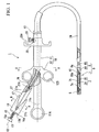
FIG. 1 is a diagram illustrating the entire appearance of a suture instrument in which a suture tool according to an embodiment of the invention is disposed. -
FIG. 2 is a diagram illustrating the entire appearance of the suture tool according to the embodiment of the invention. -
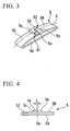
FIG. 3 is a perspective view illustrating a stopper of the suture tool. -
FIG. 4 is a side view of the stopper shown inFIG 3 . -
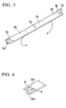
FIG. 5 is a development view illustrating the stopper shown inFIG. 3 . -
FIG. 6 is a partially enlarged view illustrating a modified example of the stopper shown inFIG. 3 . -
FIG. 7 is a partially enlarged sectional view of the suture instrument. -
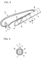
FIG. 8 is a partial perspective view of the suture instrument. -
FIG. 9 is a cross-sectional view taken along line D-D ofFIG. 8 . -
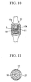
FIG. 10 is a cross-sectional view taken along line A-A ofFIG. 1 . -
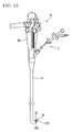
FIG. 11 is a cross-sectional view taken along line B-B ofFIG. 1 . -
FIG. 12 is a diagram illustrating the entire appearance of an endoscope used along with the suture instrument. -
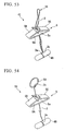
FIG. 13 is an explanatory diagram illustrating a state where a suture thread is inserted into the stopper shown inFIG. 3 . -
FIG. 14 is an explanatory diagram illustrating a state where a suture thread is inserted into the stopper shown inFIG. 3 . -
FIG. 15 is an explanatory diagram illustrating a state where a suture thread is inserted into the stopper shown inFIG 3 . -
FIG 16 is an explanatory diagram illustrating a state where a suture thread is inserted into the stopper shown inFIG 3 . -
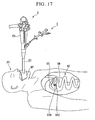
FIG 17 is an explanatory diagram illustrating an operation of the suture instrument. -
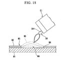
FIG 18 is an explanatory diagram illustrating an operation of the suture instrument. -
FIG. 19 is an explanatory diagram illustrating an operation of the suture instrument. -
FIG. 20 is an explanatory diagram illustrating an operation of the suture instrument. -
FIG. 21 is an explanatory diagram illustrating an operation of the suture instrument. -
FIG. 22 is an explanatory diagram illustrating an operation of the suture instrument. -
FIG 23 is an explanatory diagram illustrating an operation of the suture instrument. -
FIG. 24 is an explanatory diagram illustrating an operation of the suture instrument. -
FIG. 25 is an explanatory diagram illustrating an operation of the suture instrument. -
FIG 26 is an explanatory diagram illustrating an operation of the suture instrument. -
FIG. 27 is an explanatory diagram illustrating an operation of the suture instrument. -
FIG. 28 is an explanatory diagram illustrating an operation of the suture instrument. -
FIG. 29 is an explanatory diagram illustrating an operation of the suture instrument. -
FIG. 30 is an explanatory diagram illustrating an operation of the suture instrument. -
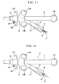
FIG. 31 is an explanatory diagram illustrating an operation of the suture instrument. -
FIG. 32 is an explanatory diagram illustrating an operation of the suture instrument. -
FIG. 33 is an explanatory diagram illustrating an operation of the suture instrument. -
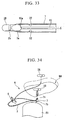
FIG. 34 is an explanatory diagram illustrating an operation of the suture instrument. -
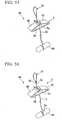
FIG. 35 is an explanatory diagram illustrating an operation of the suture instrument. -
FIG. 36 is an explanatory diagram illustrating an operation of the suture instrument. -
FIG. 37 is an explanatory diagram illustrating an operation of the suture instrument. -
FIG. 38 is an explanatory diagram illustrating an operation of the suture instrument. -
FIG. 39 is an explanatory diagram illustrating an operation of the suture instrument. -
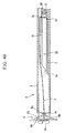
FIG 40 is an explanatory diagram illustrating an operation of the suture instrument. -
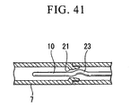
FIG 41 is an explanatory diagram illustrating an operation of the suture instrument. -
FIG 42 is an explanatory diagram illustrating an operation of the suture instrument. -
FIG 43 is an explanatory diagram illustrating an operation of the suture instrument. -
FIG 44 is a perspective view illustrating a modified example of a suture needle of the suture instrument. -
FIG 45 is a perspective view illustrating a modified example of the suture needle of the suture instrument. -
FIG. 46 is a cross-sectional view taken along line I-I ofFIG. 45 . -
FIG 47 is a cross-sectional view taken along line II-II ofFIG. 45 . -
FIG. 48 is a partially enlarged perspective view illustrating a modified example of the suture instrument. -
FIG. 49 is an explanatory diagram illustrating an operation of the suture instrument shown inFIG. 48 . -
FIG 50 is a partially enlarged perspective view illustrating a modified example of the suture instrument. -
FIG 51 is a partially enlarged perspective view illustrating a modified example of the suture instrument. -
FIG 52 is a partially enlarged perspective view illustrating a modified example of the suture instrument. -
FIG 53 is an entire perspective view illustrating a modified example of the suture instrument. -
FIG. 54 is an entire perspective view illustrating a modified example of the suture instrument. -
FIG 55 is an entire perspective view illustrating a modified example of the suture instrument. -
FIG 56 is an entire perspective view illustrating a modified example of the suture instrument. -
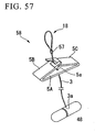
FIG. 57 is an entire perspective view illustrating a modified example of the suture instrument. - Exemplary embodiments of the invention will be described in detail below. In the following description, like elements are denoted by like reference numerals and repeated description is omitted.
- As shown in
FIGS. 1 and2 , a suture tool 6 according to an embodiment of the invention has an anchor 2 locked to a biological tissue not shown, a suture thread 3 drawn out of the anchor 2, and a stopper 5 disposed on the suture thread 3, and is used along with a suture instrument 1, which includes a sheath 9 having a hollow puncture needle 7 which has a hard needle portion 7A having an opening 7a formed at the front end thereof and which houses the anchor 2 and an outer sheath 8 which houses the puncture needle 7 so as to advance and retreat; a pusher (wire) 10 which is disposed to advance and retreat in the puncture needle 7 and of which a proximal end extends to a proximal side in a state where a distal end 10a is in contact with the anchor 2; an operating section 14 having an operating section body 11 which extends from a base end of the outer sheath 8 and a needle slider (first operating section) 12 which is fixed to a base end of the puncture needle 7 and disposed in the operating section body 11 so as to advance and retreat; a pusher operating section (wire operating section, second operating section) 13 which is connected to a base end of the pusher 10 and disposed so as to advance and retreat relative to the operating section body 11; a spring member (resilient member) 15 which has a first end 15a and a second end 15b, the first end 15a of which is connected to the pusher operating section 13, and which expands and contracts between the second end 15b and the first end 15a; a movable stopper (movable member) 16 which is connected to the second end 15b and which is movable relative to the operating section 12; and a lock member (control member) 17 which is disposed in the movable stopper 16 and which switches the movable stopper 16 between a movable state and a fixed state relative to the operating section 12. - The
anchor 2 of thesuture tool 6 includes afirst anchor 2A and asecond anchor 2B. Theanchors groove 2a in the circumferential direction at the center portion thereof. Afirst end 3a of thesuture thread 3 extends from the vicinity of thegroove 2a of thefirst anchor 2A. Thesuture thread 3 is bent back to form aloop 18 in which thepusher 10 is inserted, and asecond end 3b is connected to the vicinity of thegroove 2a of thesecond anchor 2B. - As shown in
FIGS. 3 to 6 , thestopper 5 has abase portion 5A and a pair ofbent pieces base portion 5A of thestopper 5 is provided with a through-hole 5a into which thesuture thread 3 is inserted. The pair ofbent pieces base portion 5A. - The front ends of the pair of
bent pieces thick plate portions suture thread 3 and sandwich thesuture thread 3 therebetween, at positions decentered in a direction separating each other from the center axis line C of the pair ofbent pieces thick plate portions suture thread 3. - An engaging
protrusion 5d protruding toward a gap S1 formed between a lateral edge of thebent piece 5B and thethick plate portion 5b due to the decentering is formed in thethick plate portion 5c disposed in the otherbent piece 5C opposed to thebent piece 5B. Similarly, an engagingprotrusion 5e protruding toward a gap S2 formed between a lateral edge of thebent piece 5C and thethick plate portion 5c is formed in thethick plate portion 5b disposed in thebent piece 5B. - The
stopper 5 is shaped by pressing portions other than thethick plate portions base portion 5A and the pair ofbent pieces FIG. 6 ,thick plate portions 20c and engagingprotrusions 20d with a thickness of 0.4 mm may be secured at both ends of a band-shaped thin plate member with a thickness of 0.2 mm by means of caulking or welding W to form thestopper 5. - The
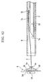
puncture needle 7 has a tube-shapedproximal side member 7B of which a front end is connected to theneedle portion 7A. Theproximal side member 7B is formed of a soft flexible member. Theproximal side member 7B is formed of an extruded tube of PEEK (poly etherether ketone) so as to endure an expanding and contracting load accompanied with the protruding and retracting of thepuncture needle 7 relative to theouter sheath 8 and an expanding load due to the movement of thestopper 5 over thesuture thread 3 accompanied with a tightening of a biological tissue. - As shown in
FIGS. 7 to 9 , thepuncture needle 7 is inserted into a channel CH1 of an endoscope insertion section EI to be described later along with theouter sheath 8. Theopening 7a at the front end of thepuncture needle 7 is inclined about the longitudinal direction of thepuncture needle 7. Anintroduction hole 7b for introducing aloop 18 of thesuture thread 3 into a cavity of thepuncture needle 7 from the outside thereof is formed in a side surface of thepuncture needle 7 closer to the proximal side than the front end position of thepusher 10. Specifically, theintroduction hole 7b is disposed at a position apart from theopening 7a by the total length or more of thefirst anchor 2A and thesecond anchor 2B arranged in series. Aslit 7c having sufficient width to pass thesuture thread 3 therethrough is disposed from theopening 7a toward theintroduction hole 7b. - A
restriction member 21 for restricting the moving amount of thepusher 10 to the proximal side in thepuncture needle 7 is disposed at a position closer to the proximal side than theintroduction hole 7b of thepuncture needle 7 so as to protrude inwardly in the diameter direction. - The
restriction member 21 is disposed in the base end of theneedle portion 7A which is closer to the proximal side than theintroduction hole 7b of thepuncture needle 7 so as to protrude inwardly in the diameter direction. In therestriction member 21, the slope close to the front end of thepuncture needle 7 is steep and the slope close to the proximal side is gentle. A male screw portion is formed on the outer circumferential surface of therestriction member 21 and a female screw portion capable of engaging with the male screw portion is formed at the front end of theproximal side member 7B. Accordingly, theneedle portion 7A and theproximal side member 7B are coupled to each other with sufficient strength to endure a high expanding and contracting load and with a simple structure by allowing them to engage with each other in a screwing manner. - The inner circumferential surface of the front side of the
puncture needle 7 is provided withprotrusions 22 engaging with thegrooves 2a at the time of housing thefirst anchor 2A and thesecond anchor 2B. - The
pusher 10 is made of a thin longitudinal wire. Thepusher 10 is provided with an engagingportion 23 detachably engaging with thesuture thread 3 drawn out of theslit 7c with theanchors 2 of thesuture tool 6 housed in thepuncture needle 7. The engagingportion 23 is formed by curving a part of the front side of thepusher 10. - The
outer sheath 8 includes afront side sheath 8A which covers the front side of thepuncture needle 7 having housed thesuture tool 6 and aproximal side sheath 8B which is connected to the base end of thefront side sheath 8A to cover the proximal side. Theouter sheath 8 is constructed of densely woundmetal wires 8a in a coil shape. Thefront side sheath 8A has an inner diameter larger than that of theproximal side sheath 8B so as to house thestopper 5 and thepuncture needle 7. - The outer surface of the
proximal side sheath 8B is covered with aresin tube 24. Theresin tube 24 is closely fixed onto themetal wire 8a by means of a thermal contraction method. Alternatively, theresin tube 24 is formed by means of an extrusion molding method using a coil not shown as a core. A resin coating may be used instead of theresin tube 24. - As shown in
FIGS. 1 ,10, and 11 , agroove 11a having a U shape in the direction of the center axis C1 is formed in theoperating section body 11 and afinger laying portion 11 A is disposed in the base end of theoperating section body 11. Acontrol stopper 25 for restricting the movement of theneedle slider 12 is disposed in the front side of theoperating section body 11. Thecontrol stopper 25 is positioned in theoperating section body 11 by the use of a fixingscrew 26. Thecontrol stopper 25 is provided with a semi-circularfinger laying portion 25A. - The
needle slider 12 has a protrudingmember 12A engaging with theU-shaped groove 11a and engages with theoperating section body 11 so as to advance and retreat. At the base end of theneedle slider 12, abranch section 27 extending in the direction of a center axis C2 inclined about the center axis C1 is connected to the protrudingmember 12A. Theneedle slider 12 includes twofinger laying portions 12B. - The base end portion of the
branch section 27 is provided with a pusher through-hole 27a into which the base end of thepusher 10 is inserted. The front end of the pusher through-hole 27a is provided with aneedle fixing portion 27A which is inserted into the base end of theproximal side member 7B of thepuncture needle 7 and which is screwed similarly to the connection of the front end of theproximal side member 7B. Thebranch section 27 has a cylinder shape and is surrounded with amovable stopper 16 so as to advance and retreat. - The
pusher operating section 13 is formed in a cylinder shape and is connected to the base end of thepusher 10. - The
spring member 15 has a resilient force adjusted so that the moving distance of thepusher 10 corresponds to the length of oneanchor 2 when it is compressed to the maximum. The resilient force is adjusted to be smaller than the frictional force between thepusher 10 and thepuncture needle 7. - The
movable stopper 16 is formed in a bottomed cylindrical shape and is externally inserted to be slidable in a state where abottom portion 16a is apart by a predetermined distance from thebase end 27b of thebranch section 27. Asecond end 15b of thespring member 15 is connected to thebottom portion 16a. - The
lock member 17 protrudes from themovable stopper 16 in the longitudinal direction of thepusher operating section 13 and is resiliently deformed in a direction in which the diameter of themovable stopper 16 decreases. - The
suture instrument 1 is used along with an endoscope E, as shown inFIG. 12 . The endoscope E includes an endoscope operating section ES operated by an operator and a flexible endoscope insertion section EI extending from the endoscope operating section ES. The endoscope insertion section EI is provided with channels CH1 and CH2 into which thesuture instrument 1 and the like are inserted and which are opened at the front end of the endoscope insertion section EI. A lighting optical system EL is disposed in the front end of the endoscope insertion section EI. - Next, operations of the
suture instrument 1 and thesuture tool 6 are described along with a suturing method with reference toFIGS. 13 to 43 . The stomach is shown as an example of a hollow organ. - First, in the
stopper 5 shown inFIG. 13 , as shown inFIG. 14 , thesuture thread 3 is inserted into the through-hole 5a of thebase portion 5A and passes through while the pair ofbent pieces thick plate portions suture thread 3 is drawn in a direction d1 of thebase portion 5A, thethick plate portions thick plate portions suture thread 3, thereby restricting the movement of thesuture thread 3. - That is, when a force acts on the
suture thread 3 in a direction in which theanchors 2 are separated from thestopper 5, the pair ofbent pieces suture thread 3. That is, even when an anastomosis object to be anastomosed by thestopper 5 and theanchors 2 pushes thestopper 5 in a direction d2 toward the other end of thesuture thread 3, thethick plate portions suture thread 3 and lock the position of thestopper 5 relative to thesuture thread 3. As a result, thestopper 5 is not moved in the direction d2. - On the other hand, as shown in
FIG. 15 , when thestopper 5 is moved to be closer to theanchors 2, that is, when thesuture thread 3 is drawn in the direction d2 opposite to thebase portion 5A, thethick plate portions suture thread 3. That is, the movement of thesuture thread 3 is allowed in the direction in which theanchors 2 and thestopper 5 are closer to each other. That is, when thestopper 5 is pressed to the anastomosis object, that is, when thestopper 5 is moved in the direction d1 of one end of thesuture thread 3, thethick plate portions thick plate portions suture thread 3 is released. - As shown in
FIG. 16 , thestopper 5 is compulsorily moved in the direction d2 by means of the pressure from the anastomosis object. At this time, thebase portion 5A of thestopper 5 and the pair ofbent portions stopper 5 are substantially parallel to each other. Since this state is similar to the molded state, the bending stress hardly occurs in the pair ofbent pieces suture thread 3 is maintained without moving relative to the anastomosis object. - Next, as shown in
FIG. 17 , the endoscope insertion section El is inserted into the mouth of a patient PT wearing a mouthpiece MP and the front end of the endoscope insertion section EI is curved. As shown inFIG. 18 , an incising treatment instrument SW such as a snare is inserted into the channel CH1 of the endoscope insertion section EI to cut off a mucous membrane M3 including a pathological lesion. - On the other hand, as shown in
FIG. 19 , thefirst anchor 2A and thesecond anchor 2B of thesuture tool 6 are housed in series in thepuncture needle 7 and theprotrusion 22 is allowed to engage with thegroove 2a of thefirst anchor 2A. Thesuture thread 3 is allowed to protrude from theslit 7c and theloop 18 is introduced again into thepuncture needle 7 from theintroduction hole 7b. Thepusher 10 is allowed to be inserted into theloop 18 to engage with the engagingportion 23, thereby maintaining thestopper 5 in a state where it is housed in thepuncture needle 7. - After cutting off the mucous membrane M3, the
suture instrument 1 is inserted into the channel CH1 instead of the incising treatment instrument SW and the front end of theouter sheath 8 is allowed to protrude from the front end of the channel CH1. - In this state, as shown in
FIG. 20 , theneedle slider 12 is allowed to advance relative to theoperating section body 11 and as shown inFIG. 21 , thepuncture needle 7 is allowed to protrude from theouter sheath 8. At this time, theneedle slider 12 is moved forward by means of an operation of passing a thumb through thefinger laying portion 11A, passing one of an index finger, a middle finger, and a ring finger through thefinger laying portion 12B, and opening both fingers. Alternatively, theneedle slider 12 may be moved forward by means of an operation of passing a thumb through thefinger laying portion 12B, laying one of an index finger, a middle finger, and a ring finger on the semi-circularfinger laying portion 25A, and closing both fingers. Since the closing operation can allow a more minute adjustment than the opening operation and thus can apply a force more conveniently, the protruding amount from theouter sheath 8 and the speed of thepuncture needle 7 can be more easily controlled. - Next, as shown in
FIG. 22 , a forceps F is inserted into the channel CH2 and is allowed to protrude from the front end of the channel CH2, grasps a distal cut end M5 of a mucous-membrane lost portion M4 and pulls and holds up the distal cut end M5 in a direction apart from the mucous-membrane lost portion M4. - In this state, as shown in
FIG. 24 , the endoscope insertion section EI is curved to define the puncture direction of thepuncture needle 7. At this time, since theproximal side member 7B of thepuncture needle 7 is formed of a soft tube, the outer portion of theproximal side member 7B respect to thepusher 10 been as an axis expands in the curved direction. On the other hand, since thepusher 10 is a wire having a high rigidity and a small diameter, thepusher 10 does not expand with the curving operation. Accordingly, the engagingportion 23 of thepusher 10 engages with therestriction member 21 of thepuncture needle 7 and thus thepusher operating section 13 is relatively drawn toward thebranch section 27 along with themovable stopper 16. - Thereafter, the
needle slider 12 is allowed to advance relative to theoperating section body 11 until coming in contact with thecontrol stopper 25 so as to allow thepuncture needle 7 to protrude from the front end of theouter sheath 8. In this way, as shown inFIG. 25 , by allowing theentire suture instrument 1 or the endoscope insertion section EI to advance, thepuncture needle 7 is allowed to pass through the held-up mucous membrane M5 by means of operations of the forceps F and the endoscope. - Next, as shown in
FIG. 26 , themovable stopper 16 and thebranch section 27 are fixed to each other by grasping thelock member 17 of themovable stopper 16 along with thebranch section 27. As shown inFIG. 27 , thespring member 15 is compressed by moving thepusher operating section 13 toward the front end. At this time, thepusher 10 moves relative to thepuncture needle 7 by the length of one anchor. Accordingly, theprotrusion 22 and thegroove 2a of thefirst anchor 2A are disengaged from each other and thus thesecond anchor 2B advances, as shown inFIG. 28 , thereby extruding thefirst anchor 2A in a surface contact state toward the front end of thepuncture needle 7. Then, thegroove 2a of thesecond anchor 2B newly engages with theprotrusion 22. As a result, thefirst anchor 2A drops to the rear side of the mucous membrane M5. When thepuncture needle 7 is pulled out of the mucous membrane M5, thesuture thread 3 passes through the mucous membrane M5 and thefirst anchor 2A is detained in the distal side of the mucous-membrane lost portion M4. - Subsequently, the
lock member 17 is taken off and thus themovable stopper 16 is restored to the original shape. Here, the resilient restoring force of thespring member 15 is set smaller than the frictional force generated over the entire length between thepusher 10 and thepuncture needle 7. Accordingly, while thespring member 15 is restored to the original length in a state where thepusher 10 and thepuncture needle 7 are not relatively moved, themovable stopper 16 advances relative to thebranch section 27, as shown inFIG. 29 . - Next, the front end of the endoscope insertion section EI is moved to the place where the
second anchor 2B should be detained. Similarly to thefirst anchor 2A, as shown inFIG. 30 , the end portion of a mucous membrane M6 which is substantially symmetric with the mucous membrane M5 with the mucous-membrane lost portion M4 interposed therebetween is grasped and held up by the forceps F. By allowing theentire suture instrument 1 or the endoscope insertion section EI to advance again with thepuncture needle 7 protruding from the front end of theouter sheath 8, thepuncture needle 7 passes through the held-up mucous membrane M6. - Here, as shown in
FIG. 31 , thelock member 17 is grasped and deformed again to come in contact with thebranch section 27. As shown inFIG. 32 , thepusher operating section 13 is moved relative to themovable stopper 16 to compress thespring member 15. Accordingly, as shown inFIG. 33 , theprotrusion 22 and thegroove 2a of thesecond anchor 2B are disengaged from each other and thus thesecond anchor 2B is discharged to the rear side of the mucous membrane M6. When thepuncture needle 7 is pulled out of the mucous membrane M6, thesuture thread 3 penetrates the mucous membrane M6 and thesecond anchor 2B is detained in the proximal side of the mucous-membrane lost portion M4, as shown inFIG. 34 . - Next, as shown in
FIG. 35 , theneedle slider 12 is allowed to retreat toward the proximal side relative to theoperating section body 11. Accordingly, thepuncture needle 7 is relatively drawn into theouter sheath 8 and the front end of theouter sheath 8 comes in contact with thestopper 5 of thesuture tool 6, as shown inFIG. 36 . As shown inFIG 37 , by moving theneedle slider 12 to the proximal side, the distance between thestopper 5 and theanchors 2 is reduced. The reduction in distance between theanchors anchors FIG. 38 , thestopper 5 comes in contact with the mucous membranes M5 and M6 and is fastened, thereby reducing the mucous-membrane lost portion M4. - As shown in
FIG. 39 , themovable stopper 16 is allowed to retreat to the proximal side relative to thebranch section 27. At this time, as shown inFIGS. 40 and41 , theloop 18 of thesuture thread 3 is disengaged from the engagingportion 23 of thepusher 10 and the engagingportion 23 is resiliently deformed so as to pass over therestriction member 21, thereby moving thepusher 10 to the proximal side relative to thepuncture needle 7. Here, when thesuture instrument 1 or the endoscope insertion section EI is allowed to retreat apart from the mucous-membrane lost portion M4, theloop 18 is drawn from theintroduction hole 7b of thepuncture needle 7 to the outside of thepuncture needle 7, as shown inFIG. 42 . In this way, as shown inFIG. 43 , thesuture tool 6 is separated from thesuture instrument 1 in the state where thesuture thread 3 is maintained so as not to be loosened by thestopper 5, thereby detaining thesuture tool 6. - According to the
suture instrument 1, even when thesheath 9 is curved, it is possible to move thepusher operating section 13 relative to theoperating section body 11 with the expansion and contraction of thesheath 9 by setting themovable stopper 16 to the movable state and setting thespring member 15 to the expansible state. By setting themovable stopper 16 to the fixed state by the use of thelock member 17 and setting thespring member 15 to the contractible state, it is possible to move the position of thefront end 10a of thepusher 10 relative to thesheath 9 by a predetermined distance. Accordingly, regardless of the curvedness of thesheath 9, it is possible to allow thepusher 10 to precisely advance and retreat relative to thesheath 9 by a predetermined distance with a simple operation. - At this time, by grasping the
lock member 17 to come in contact with thebranch section 27, it is possible to allow themovable stopper 16 to be fixed to theoperating section body 11. On the other hand, when thelock member 17 is not deformed, themovable stopper 16 can be set to the movable state relative to thebranch section 27. - Since the
movable stopper 16 and thebranch section 27 are connected to each other with thespring member 15, the expanding and contracting amount of thespring member 15 can be easily controlled, thereby allowing thepusher 10 to advance and retreat with high precision. - The engaging
portion 23 is disposed in thepusher 10. Accordingly, even after thepuncture needle 7 punctures the biological tissue and theanchors 2 are detained by moving thepusher 10, thesuture thread 3 can be held by thepusher 10. Therefore, by drawing thepuncture needle 7 into the proximal side of theouter sheath 8 along with thepusher 10 in a state where theouter sheath 8 is in contact with thestopper 5 of thesuture tool 6, it is possible to move thestopper 5 toward theanchors 2. Thereafter, by disengaging thesuture thread 3 from thepusher 10, it is possible to detain thesuture tool 6 in the biological tissue. Accordingly, it is possible to continuously perform the detention of thesuture tool 6 and the suture, without replacing a plurality of treatment tools. - At this time, by introducing the
loop 18 of thesuture thread 3 into thepuncture needle 7 through theintroduction hole 7b of thepuncture needle 7 and inserting thepusher 10 into theloop 18, it is possible to allow theloop 18 to easily engage with the engagingportion 23. - By allowing the
needle slider 12 to advance and retreat relative to theoperating section body 11, it is possible to allow thepuncture needle 7 to protrude and retract relative to theouter sheath 8. By allowing thepusher operating section 13 to advance and retreat relative to theneedle slider 12, it is possible to allow thepusher 10 to advance and retreat relative to thepuncture needle 7. Here, since thebranch section 27 is inclined about theoperating section body 11, it is possible to continuously operate theneedle slider 12 and thepusher operating section 13 without changing both portions at the time of operating both portions to advance and retreat. - The
outer sheath 8 has a coil shape. As a result, even when thepuncture needle 7 is allowed to retract into theouter sheath 8 with thesuture thread 3 engaging with the engagingportion 23 and thestopper 5 of thesuture thread 3 is pressed by the front end of theouter sheath 8, it can reliably endure the compressing force generated in the axis direction of theouter sheath 8. - The
proximal side sheath 8B is covered with theresin tube 24. As a result, when thepuncture needle 7 is extruded from theouter sheath 8, it can reliably endure the drawing force generated in theouter sheath 8. - As shown in
FIG 41 , therestriction member 21 is disposed in thepuncture needle 7. As a result, when thepusher 10 is inserted into thepuncture needle 7 at the time of assembly, thepusher 10 can be inserted while coming in contact with the gentle slope portion on the proximal side of therestriction member 21, thereby easily performing the assembly work. On the other hand, when thepusher 10 is accidentally moved relatively toward the base end of thepuncture needle 7 after the assembly, the engagingportion 23 comes in contact with the sharp slope portion of therestriction member 21, thereby restricting the further movement of thepusher 10. - According to the
suture tool 6, when thesuture thread 3 is sandwiched by thethick plate portions bent pieces suture tool 6, the contact area between the pair ofbent pieces suture thread 3 can be increased more suitably, thereby reducing the stress generated in the pair ofbent pieces stopper 5 can maintain a stable fixing force to the biological tissue. - When the
suture thread 3 is inserted through thestopper 5, the pair ofbent pieces base portion 5A. However, when thestopper 5 is moved relative to thesuture thread 3 and is fixed to the biological tissue, the pair ofbent pieces base portion 5A become substantially parallel to each other similarly to the initial state. That is, since the pair ofbent pieces suture thread 3 is not reduced while moving thestopper 5. As a result, it is possible to satisfactorily suppress the movement of thebent pieces suture thread 3 while thestopper 5 is detained. - Since the
thick plate portions protrusions suture thread 3 by the use of thestopper 5, it is possible to satisfactorily prevent the mismatch between thebent pieces bent pieces - As shown in
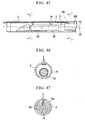
FIGS. 44 to 47 , the portion of apuncture needle 28 in which anintroduction hole 28b is formed may be decentered to form a protrudingportion 28A. This uses the space S formed between thepuncture needle 28 and theouter sheath 8 because the center axis C3 of theouter sheath 8 and the center axis C4 of thepuncture needle 28 are offset when thepuncture needle 28 is disposed in theouter sheath 8. - As shown in
FIG. 48 , an engagingportion 31 of asuture instrument 30 may be disposed in a slit shape in the side surface of apuncture needle 32. - In the
suture instrument 30, thefirst anchor 2A and thesecond anchor 2B of thesuture tool 6 are housed in series in thepuncture needle 32, thesuture thread 3 is allowed to protrude from aslit 32c, and theloop 18 is allowed to engage with the engagingportion 31, thereby maintaining thestopper 5 in a state where it is housed in thepuncture needle 32. - By means of the same operation as the first embodiment, an anchor (not shown) of the
suture tool 6 is detained. When thesuture thread 3 is detached from the engagingportion 31, thepuncture needle 32 is allowed to once protrude from theouter sheath 8 and thepuncture needle 32 is shaken. At this time, thesuture thread 3 is disengaged from the engagingportion 31, as shown inFIG. 49 . - According to the
suture instrument 30, since the engagingportion 31 has a slit shape, it is possible to allow theloop 18 to easily engage with the surface of thepuncture needle 32 by hooking a part of thesuture thread 3 thereto. - As shown in
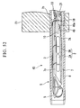
FIG. 50 , a suture instrument 33 may include alid 35 covering the engagingportion 31. Thelid 35 engages with aguide groove 37 formed in the surface of apuncture needle 36 and is connected to a drawingmember 38 so as to move along theguide groove 37. - According to the suture instrument 33, it is possible to satisfactorily prevent the
suture thread 3 from erroneously departing from the engagingportion 31, by allowing theloop 18 to engage with the engagingportion 31 and then covering the engaging portion with thelid 35. By drawing the drawingmember 38 to move thelid 35, it is possible to easily disengage theloop 18 from the engagingportion 31. - As shown in
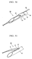
FIG. 51 , an engagingportion 41 of asuture instrument 40 may be disposed to protrude from the side surface of apuncture needle 42. - The
suture instrument 40 allows theloop 18 to engage with the engagingportion 41 and detains an anchor not shown. When thesuture thread 3 is disengaged from the engagingportion 41, thesuture thread 3 is disengaged from the engagingportion 41 by allowing thepuncture needle 42 to once protrude from theouter sheath 8 and shaking thepuncture needle 42. - According to the
suture instrument 40, since the engagingportion 41 is disposed to protrude, it is possible to allow theloop 18 of thesuture thread 3 to easily engage with the surface of thepuncture needle 42. - As shown in
FIG. 52 , thepusher 10 may be provided with acutting edge 46 which can cut thesuture thread 3 of asuture instrument 45. - Here, the
cutting edge 46 is disposed closer to the front end of thepusher 10 than the engagingportion 23 by a shorter distance than the distance between theintroduction hole 7b and therestriction member 21. Acutting edge face 46a is disposed toward only the proximal side. - In the
suture instrument 45, by means of the same operation as the first embodiment, thefirst anchor 2A and thesecond anchor 2B of thesuture tool 6 are housed in series in thepuncture needle 7, thesuture thread 3 is allowed to protrude from theslit 7c, and theloop 18 is introduced into thepuncture needle 7 through theintroduction hole 7b, and the front end of thepusher 10 is inserted into theloop 18, thereby allowing theloop 18 to engage with the engagingportion 23. Here, since thecutting edge face 46a is disposed to the proximal side, theloop 18 is not cut by thecutting edge 46 at the time of allowing theloop 18 to engage with the engagingportion 23. - When the
suture thread 3 is disengaged from the engagingportion 23, thepusher 10 is drawn into the proximal side relative to thepuncture needle 7. At this time, since theloop 18 comes in contact with thecutting edge face 46a, theloop 18 is cut and thesuture thread 3 is disengaged from the engagingportion 23. - According to the
suture instrument 45, by relatively moving thepusher 10 in a direction different from the direction in which thepusher 10 is inserted into theloop 18 of thesuture thread 3, it is possible to easily cut theloop 18 with thecutting edge 46 and to disengage theloop 18 from the engagingportion 23. - As shown in
FIG. 53 , when asuture tool 47 has only oneanchor 48, thefirst end 3a and thesecond end 3b of thesuture thread 3 may be connected to the same position of theanchor 48. - As shown in
FIG. 54 , asuture tool 51 in which thefirst end 3a of thesuture thread 3 is connected to theanchor 48 and aring 50 instead of theloop 18 is disposed at thesecond end 3b may be used. - As shown in
FIG. 55 , asuture tool 53 in which a second end of asuture thread 52 is shaped in advance in aloop 18 may be used. As shown inFIG. 56 , asuture tool 56 in which theloop 18 is formed by bending back thesuture thread 3 and tying thesecond end 3b to an intermediate portion of thesuture thread 3 to form aknot 55 may be used. Alternatively, as shown inFIG 57 , asuture tool 58 in which theloop 18 is formed by caulking thesuture thread 3 with acaulking member 57 may be used. - Although exemplary embodiments of the invention have been described hitherto, the invention is not limited to the exemplary embodiments. The invention is not restricted by the above description, but only by the scope of the appended claims.
Claims (4)
- A suture tool (6, 47, 51, 53, 56, 58) comprising an engaging member (2, 48) adapted to be detain in a biological tissue, a suture thread (3, 52) which is drawn from the engaging member, and a fixing member (5) adapted to restrict a looseness of the suture thread from the biological tissue anastomosed by the suture thread the fixing member (5) is penetrated by the suture thread and includes:a base portion (5A) which has a longitudinal plate shape and which has a through-hole (5a) through which the suture thread passes; anda pair of bent pieces (5B, 5C) of which ends are opposed to each other by bending both ends of the base portion toward the center thereof, and the suture tool is characterized in thatthe fixing member includes thick plate portions (5b, 5c) which interpose the suture thread therebetween and are disposed at the ends of the pair of bent pieces, respectively, and a thickness of each of the thick plate portions in an insertion direction of the suture thread is thicker than that of other portion of the pair of bent pieces.
- The suture tool according to claim 1, wherein the pair of bent pieces are substantially parallel to the base portion.
- The suture tool according to claim 1, wherein the thick plate portions are decentered in a direction in which the thick plate portions are separated from the center axis line of the pair of bent pieces, and
an engaging protrusion (5d) which protrudes toward a gap formed between a lateral edge of the bent piece and the thick plate portion due to the decentering is provided in the thick plate portion disposed in the other bent piece opposed to the bent piece. - The suture tool according to Claim 1, wherein the thick plate portions integrally form a body along with the pair of bent pieces.
Applications Claiming Priority (1)
| Application Number | Priority Date | Filing Date | Title |
|---|---|---|---|
| US11/711,265 US7780702B2 (en) | 2007-02-27 | 2007-02-27 | Suture tool |
Publications (3)
| Publication Number | Publication Date |
|---|---|
| EP1964520A2 EP1964520A2 (en) | 2008-09-03 |
| EP1964520A3 EP1964520A3 (en) | 2009-01-07 |
| EP1964520B1 true EP1964520B1 (en) | 2011-03-09 |
Family
ID=39535144
Family Applications (1)
| Application Number | Title | Priority Date | Filing Date |
|---|---|---|---|
| EP07022958A Expired - Fee Related EP1964520B1 (en) | 2007-02-27 | 2007-11-27 | Suture tool |
Country Status (4)
| Country | Link |
|---|---|
| US (1) | US7780702B2 (en) |
| EP (1) | EP1964520B1 (en) |
| JP (1) | JP5259201B2 (en) |
| DE (1) | DE602007012996D1 (en) |
Cited By (3)
| Publication number | Priority date | Publication date | Assignee | Title |
|---|---|---|---|---|
| US9173645B2 (en) | 2010-04-27 | 2015-11-03 | DePuy Synthes Products, Inc. | Anchor assembly including expandable anchor |
| US9451938B2 (en) | 2010-04-27 | 2016-09-27 | DePuy Synthes Products, Inc. | Insertion instrument for anchor assembly |
| US9597064B2 (en) | 2010-04-27 | 2017-03-21 | DePuy Synthes Products, Inc. | Methods for approximating a tissue defect using an anchor assembly |
Families Citing this family (38)
| Publication number | Priority date | Publication date | Assignee | Title |
|---|---|---|---|---|
| US7887551B2 (en) | 1999-12-02 | 2011-02-15 | Smith & Nephew, Inc. | Soft tissue attachment and repair |
| EP2094167B1 (en) | 2006-11-30 | 2011-06-29 | Wilson-Cook Medical, Inc. | Visceral anchors for purse-string closure of perforations |
| EP2155071B1 (en) * | 2007-05-25 | 2014-07-16 | Cook Medical Technologies LLC | Medical devices and systems for closing perforations |
| EP2150183B1 (en) | 2007-05-31 | 2013-03-20 | Cook Medical Technologies LLC | Suture lock |
| AU2008304583B2 (en) * | 2007-09-25 | 2012-03-29 | Cook Medical Technologies Llc | Medical devices, systems, and methods for using tissue anchors |
| US20090157099A1 (en) * | 2007-12-18 | 2009-06-18 | Wilson-Cook Medical, Inc. | Device and method for placement of tissue anchors |
| CA2733933C (en) | 2008-08-19 | 2014-03-11 | Wilson-Cook Medical Inc. | Apparatus for removing lymph nodes or anchoring into tissue during a translumenal procedure |
| US8192461B2 (en) | 2008-09-11 | 2012-06-05 | Cook Medical Technologies Llc | Methods for facilitating closure of a bodily opening using one or more tacking devices |
| EP2346411B1 (en) * | 2008-10-06 | 2013-10-02 | Cook Medical Technologies LLC | Endcap for safely deploying tissue anchors |
| EP2369999B1 (en) * | 2008-11-26 | 2022-04-13 | Smith & Nephew, Inc. | Tissue repair device |
| JP5559809B2 (en) * | 2008-12-05 | 2014-07-23 | クック メディカル テクノロジーズ エルエルシー | Tissue anchor that closes the hole in a drawstring fashion |
| AU2009324819B2 (en) | 2008-12-09 | 2014-04-17 | Cook Medical Technologies Llc | Retractable tacking device |
| CA2747233C (en) | 2008-12-19 | 2014-08-12 | John A. Karpiel | Clip devices and methods of delivery and deployment |
| WO2010115072A1 (en) | 2009-04-03 | 2010-10-07 | Wilson-Cook Medical, Inc. | Tissue anchors and medical devices for rapid deployment of tissue anchors |
| AU2010232485B2 (en) | 2009-04-03 | 2013-11-07 | Cook Medical Technologies Llc | Medical devices, systems, and methods for rapid deployment and fixation of tissue anchors |
| JP2012527970A (en) | 2009-05-28 | 2012-11-12 | クック メディカル テクノロジーズ エルエルシー | Hail-fastening device and hail-fastening device deployment method |
| US8828053B2 (en) | 2009-07-24 | 2014-09-09 | Depuy Mitek, Llc | Methods and devices for repairing and anchoring damaged tissue |
| US8814903B2 (en) | 2009-07-24 | 2014-08-26 | Depuy Mitek, Llc | Methods and devices for repairing meniscal tissue |
| US10959840B2 (en) | 2010-01-20 | 2021-03-30 | Micro Interventional Devices, Inc. | Systems and methods for affixing a prosthesis to tissue |
| US10058314B2 (en) | 2010-01-20 | 2018-08-28 | Micro Interventional Devices, Inc. | Tissue closure device and method |
| US9980708B2 (en) | 2010-01-20 | 2018-05-29 | Micro Interventional Devices, Inc. | Tissue closure device and method |
| CA2825186A1 (en) | 2010-01-20 | 2011-07-28 | Michael P. Whitman | Tissue repair implant and delivery device and method |
| US10743854B2 (en) | 2010-01-20 | 2020-08-18 | Micro Interventional Devices, Inc. | Tissue closure device and method |
| US8475525B2 (en) | 2010-01-22 | 2013-07-02 | 4Tech Inc. | Tricuspid valve repair using tension |
| US20110218191A1 (en) * | 2010-03-03 | 2011-09-08 | Boehringer Ingelheim Vetmedica Gmbh | Use of meloxicam for the long term-treatment of kidney disorders in cats |
| EP2556798A4 (en) * | 2010-04-06 | 2014-09-03 | Hitachi Chemical Co Ltd | Polymer molded body for pulling biological tissue, medical pulling member using same, and medical pulling tool |
| US9743919B2 (en) | 2010-04-27 | 2017-08-29 | DePuy Synthes Products, Inc. | Stitch lock for attaching two or more structures |
| AU2011354722B2 (en) * | 2011-01-14 | 2016-06-02 | Synthes Gmbh | Insertion instrument for anchor assembley |
| US10022114B2 (en) * | 2013-10-30 | 2018-07-17 | 4Tech Inc. | Percutaneous tether locking |
| US10085735B2 (en) * | 2014-10-29 | 2018-10-02 | Smith & Nephew, Inc. | Modular tissue repair kit and devices and method related thereto |
| US10702260B2 (en) | 2016-02-01 | 2020-07-07 | Medos International Sàrl | Soft tissue fixation repair methods using tissue augmentation scaffolds |
| US11484401B2 (en) | 2016-02-01 | 2022-11-01 | Medos International Sarl | Tissue augmentation scaffolds for use in soft tissue fixation repair |
| EP3537990A4 (en) * | 2016-11-11 | 2020-08-05 | Tack Surgical, LLC | Tissue fixation and closure suture articles and suture placement devices |
| EP3537991A4 (en) | 2016-11-13 | 2020-04-29 | Anchora Medical Ltd. | Minimally-invasive tissue suturing device |
| AU2018203301B2 (en) * | 2017-06-09 | 2024-02-08 | Medos International Sarl | Tissue augmentation tacks for use with soft tissue fixation repair systems and methods |
| US11375994B2 (en) * | 2019-07-12 | 2022-07-05 | Abbot Cardiovascular Systems, Inc. | Methods, systems, and devices for positioning sutures for closing an opening in tissue |
| WO2021165945A2 (en) * | 2020-02-20 | 2021-08-26 | Palliare Limited | A suturing device |
| USD977639S1 (en) | 2020-11-20 | 2023-02-07 | Palliare Limited | Suture |
Family Cites Families (19)
| Publication number | Priority date | Publication date | Assignee | Title |
|---|---|---|---|---|
| US2583530A (en) * | 1947-01-30 | 1952-01-29 | Ericsson Telefon Ab L M | Electrical connecting terminal strap |
| US3673640A (en) * | 1971-01-13 | 1972-07-04 | Dwight C Brown | Bag closure |
| US4217902A (en) * | 1977-05-02 | 1980-08-19 | March Alfred L | Hemostatic clip |
| GB2112648B (en) | 1981-11-11 | 1985-05-22 | Gegauf Fritz Ag | Set of accessory equipment for surgical suturing, method for preparing suturing material for a surgical suture, and surgical process for closing of a wound |
| CH687060A5 (en) * | 1994-02-11 | 1996-09-13 | Alice Walder Utz Dr | Piece surgical clip. |
| US6099553A (en) * | 1998-05-21 | 2000-08-08 | Applied Medical Resources Corporation | Suture clinch |
| US6648903B1 (en) * | 1998-09-08 | 2003-11-18 | Pierson, Iii Raymond H. | Medical tensioning system |
| ATE324072T1 (en) * | 1998-12-30 | 2006-05-15 | Ethicon Inc | THREAD SECURING DEVICE |
| US6165204A (en) | 1999-06-11 | 2000-12-26 | Scion International, Inc. | Shaped suture clip, appliance and method therefor |
| ATE212527T1 (en) * | 2000-11-03 | 2002-02-15 | Radi Medical Systems | DEVICE FOR SEALING AND CLOSING WOUNDS |
| DK1291034T3 (en) | 2001-09-10 | 2006-09-25 | Thermocore Medical Systems N V | Catheter position device |
| US20040236372A1 (en) * | 2003-05-20 | 2004-11-25 | Anspach William E. | Suture clamp |
| JP4166632B2 (en) | 2003-06-06 | 2008-10-15 | オリンパス株式会社 | Suture device |
| US20050251208A1 (en) * | 2004-05-07 | 2005-11-10 | Usgi Medical Inc. | Linear anchors for anchoring to tissue |
| US8951285B2 (en) | 2005-07-05 | 2015-02-10 | Mitralign, Inc. | Tissue anchor, anchoring system and methods of using the same |
| US7875041B2 (en) * | 2005-09-28 | 2011-01-25 | Olympus Medical Systems Corp. | Suturing method for penetrating hole |
| US7896895B2 (en) * | 2005-11-23 | 2011-03-01 | Ethicon Endo-Surgery, Inc. | Surgical clip and applier device and method of use |
| US20070276437A1 (en) * | 2006-05-25 | 2007-11-29 | Mitralign, Inc. | Lockers for surgical tensioning members and methods of using the same to secure surgical tensioning members |
| JP4145331B2 (en) * | 2006-06-01 | 2008-09-03 | オリンパス株式会社 | Suture and endoscope |
-
2007
- 2007-02-27 US US11/711,265 patent/US7780702B2/en active Active
- 2007-11-27 DE DE602007012996T patent/DE602007012996D1/en active Active
- 2007-11-27 EP EP07022958A patent/EP1964520B1/en not_active Expired - Fee Related
-
2008
- 2008-01-24 JP JP2008014120A patent/JP5259201B2/en not_active Expired - Fee Related
Cited By (3)
| Publication number | Priority date | Publication date | Assignee | Title |
|---|---|---|---|---|
| US9173645B2 (en) | 2010-04-27 | 2015-11-03 | DePuy Synthes Products, Inc. | Anchor assembly including expandable anchor |
| US9451938B2 (en) | 2010-04-27 | 2016-09-27 | DePuy Synthes Products, Inc. | Insertion instrument for anchor assembly |
| US9597064B2 (en) | 2010-04-27 | 2017-03-21 | DePuy Synthes Products, Inc. | Methods for approximating a tissue defect using an anchor assembly |
Also Published As
| Publication number | Publication date |
|---|---|
| DE602007012996D1 (en) | 2011-04-21 |
| US7780702B2 (en) | 2010-08-24 |
| JP5259201B2 (en) | 2013-08-07 |
| EP1964520A3 (en) | 2009-01-07 |
| US20080208218A1 (en) | 2008-08-28 |
| JP2008206972A (en) | 2008-09-11 |
| EP1964520A2 (en) | 2008-09-03 |
Similar Documents
| Publication | Publication Date | Title |
|---|---|---|
| EP1964520B1 (en) | Suture tool | |
| EP1964521B1 (en) | Suture instrument | |
| US8308766B2 (en) | Endoscopic treatment instrument | |
| US7998150B2 (en) | Suturing device | |
| EP1844718B1 (en) | Medical suture and ligature instrument and medical suture and ligature tool | |
| JP4059656B2 (en) | Biological tissue clip device | |
| CN103228223B (en) | There is the armarium of detachable pivotable jaws | |
| US8298249B2 (en) | Medical ligating apparatus | |
| AU2007285898B2 (en) | Suturing device | |
| EP2149337B1 (en) | Suturing device | |
| JP2002272751A (en) | Clip device for biomedical tissue | |
| US20090005792A1 (en) | Medical Suturing and Ligating Apparatus | |
| JP7209012B2 (en) | Clip unit and endoscope clip | |
| JP4709822B2 (en) | Biological tissue clip device | |
| US8939998B2 (en) | Medical suture and ligature instrument and medical suture and ligature tool | |
| CN114585312A (en) | Systems, devices, and related methods for fastening tissue |
Legal Events
| Date | Code | Title | Description |
|---|---|---|---|
| PUAI | Public reference made under article 153(3) epc to a published international application that has entered the european phase |
Free format text: ORIGINAL CODE: 0009012 |
|
| AK | Designated contracting states |
Kind code of ref document: A2 Designated state(s): AT BE BG CH CY CZ DE DK EE ES FI FR GB GR HU IE IS IT LI LT LU LV MC MT NL PL PT RO SE SI SK TR |
|
| AX | Request for extension of the european patent |
Extension state: AL BA HR MK RS |
|
| PUAL | Search report despatched |
Free format text: ORIGINAL CODE: 0009013 |
|
| AK | Designated contracting states |
Kind code of ref document: A3 Designated state(s): AT BE BG CH CY CZ DE DK EE ES FI FR GB GR HU IE IS IT LI LT LU LV MC MT NL PL PT RO SE SI SK TR |
|
| AX | Request for extension of the european patent |
Extension state: AL BA HR MK RS |
|
| 17P | Request for examination filed |
Effective date: 20090216 |
|
| 17Q | First examination report despatched |
Effective date: 20090318 |
|
| AKX | Designation fees paid |
Designated state(s): DE FR GB IE |
|
| GRAP | Despatch of communication of intention to grant a patent |
Free format text: ORIGINAL CODE: EPIDOSNIGR1 |
|
| GRAS | Grant fee paid |
Free format text: ORIGINAL CODE: EPIDOSNIGR3 |
|
| GRAA | (expected) grant |
Free format text: ORIGINAL CODE: 0009210 |
|
| AK | Designated contracting states |
Kind code of ref document: B1 Designated state(s): DE FR GB IE |
|
| REG | Reference to a national code |
Ref country code: GB Ref legal event code: FG4D |
|
| REG | Reference to a national code |
Ref country code: IE Ref legal event code: FG4D |
|
| REF | Corresponds to: |
Ref document number: 602007012996 Country of ref document: DE Date of ref document: 20110421 Kind code of ref document: P |
|
| REG | Reference to a national code |
Ref country code: DE Ref legal event code: R096 Ref document number: 602007012996 Country of ref document: DE Effective date: 20110421 |
|
| PLBE | No opposition filed within time limit |
Free format text: ORIGINAL CODE: 0009261 |
|
| STAA | Information on the status of an ep patent application or granted ep patent |
Free format text: STATUS: NO OPPOSITION FILED WITHIN TIME LIMIT |
|
| 26N | No opposition filed |
Effective date: 20111212 |
|
| REG | Reference to a national code |
Ref country code: DE Ref legal event code: R097 Ref document number: 602007012996 Country of ref document: DE Effective date: 20111212 |
|
| PGFP | Annual fee paid to national office [announced via postgrant information from national office to epo] |
Ref country code: IE Payment date: 20131112 Year of fee payment: 7 |
|
| PGFP | Annual fee paid to national office [announced via postgrant information from national office to epo] |
Ref country code: GB Payment date: 20141126 Year of fee payment: 8 Ref country code: FR Payment date: 20141110 Year of fee payment: 8 |
|
| REG | Reference to a national code |
Ref country code: IE Ref legal event code: MM4A |
|
| PG25 | Lapsed in a contracting state [announced via postgrant information from national office to epo] |
Ref country code: IE Free format text: LAPSE BECAUSE OF NON-PAYMENT OF DUE FEES Effective date: 20141127 |
|
| REG | Reference to a national code |
Ref country code: DE Ref legal event code: R082 Ref document number: 602007012996 Country of ref document: DE Representative=s name: WUESTHOFF & WUESTHOFF, PATENTANWAELTE PARTG MB, DE Ref country code: DE Ref legal event code: R081 Ref document number: 602007012996 Country of ref document: DE Owner name: OLYMPUS CORPORATION, JP Free format text: FORMER OWNER: OLYMPUS MEDICAL SYSTEMS CORP., TOKYO, JP |
|
| GBPC | Gb: european patent ceased through non-payment of renewal fee |
Effective date: 20151127 |
|
| REG | Reference to a national code |
Ref country code: FR Ref legal event code: ST Effective date: 20160729 |
|
| PG25 | Lapsed in a contracting state [announced via postgrant information from national office to epo] |
Ref country code: GB Free format text: LAPSE BECAUSE OF NON-PAYMENT OF DUE FEES Effective date: 20151127 |
|
| PG25 | Lapsed in a contracting state [announced via postgrant information from national office to epo] |
Ref country code: FR Free format text: LAPSE BECAUSE OF NON-PAYMENT OF DUE FEES Effective date: 20151130 |
|
| PGFP | Annual fee paid to national office [announced via postgrant information from national office to epo] |
Ref country code: DE Payment date: 20181120 Year of fee payment: 12 |
|
| REG | Reference to a national code |
Ref country code: DE Ref legal event code: R119 Ref document number: 602007012996 Country of ref document: DE |
|
| PG25 | Lapsed in a contracting state [announced via postgrant information from national office to epo] |
Ref country code: DE Free format text: LAPSE BECAUSE OF NON-PAYMENT OF DUE FEES Effective date: 20200603 |