EP1965083A1 - Hydraulic unit and method of controlling speed of motor in hydraulic unit - Google Patents
Hydraulic unit and method of controlling speed of motor in hydraulic unit Download PDFInfo
- Publication number
- EP1965083A1 EP1965083A1 EP07806100A EP07806100A EP1965083A1 EP 1965083 A1 EP1965083 A1 EP 1965083A1 EP 07806100 A EP07806100 A EP 07806100A EP 07806100 A EP07806100 A EP 07806100A EP 1965083 A1 EP1965083 A1 EP 1965083A1
- Authority
- EP
- European Patent Office
- Prior art keywords
- oil pressure
- motor
- command value
- current command
- load
- Prior art date
- Legal status (The legal status is an assumption and is not a legal conclusion. Google has not performed a legal analysis and makes no representation as to the accuracy of the status listed.)
- Granted
Links
- 238000000034 method Methods 0.000 title claims description 11
- 238000012937 correction Methods 0.000 claims abstract description 79
- 230000007274 generation of a signal involved in cell-cell signaling Effects 0.000 claims abstract description 5
- 230000004044 response Effects 0.000 description 6
- 238000000465 moulding Methods 0.000 description 4
- 238000001514 detection method Methods 0.000 description 2
- 230000004048 modification Effects 0.000 description 2
- 238000012986 modification Methods 0.000 description 2
- 238000012545 processing Methods 0.000 description 2
- 230000001133 acceleration Effects 0.000 description 1
- 230000004069 differentiation Effects 0.000 description 1
- 230000000694 effects Effects 0.000 description 1
- 239000012530 fluid Substances 0.000 description 1
- 230000006872 improvement Effects 0.000 description 1
- 238000004519 manufacturing process Methods 0.000 description 1
- 230000010355 oscillation Effects 0.000 description 1
- 238000004904 shortening Methods 0.000 description 1
- 238000012360 testing method Methods 0.000 description 1
Images


Classifications
-
- F—MECHANICAL ENGINEERING; LIGHTING; HEATING; WEAPONS; BLASTING
- F04—POSITIVE - DISPLACEMENT MACHINES FOR LIQUIDS; PUMPS FOR LIQUIDS OR ELASTIC FLUIDS
- F04B—POSITIVE-DISPLACEMENT MACHINES FOR LIQUIDS; PUMPS
- F04B49/00—Control, e.g. of pump delivery, or pump pressure of, or safety measures for, machines, pumps, or pumping installations, not otherwise provided for, or of interest apart from, groups F04B1/00 - F04B47/00
- F04B49/20—Control, e.g. of pump delivery, or pump pressure of, or safety measures for, machines, pumps, or pumping installations, not otherwise provided for, or of interest apart from, groups F04B1/00 - F04B47/00 by changing the driving speed
-
- F—MECHANICAL ENGINEERING; LIGHTING; HEATING; WEAPONS; BLASTING
- F04—POSITIVE - DISPLACEMENT MACHINES FOR LIQUIDS; PUMPS FOR LIQUIDS OR ELASTIC FLUIDS
- F04B—POSITIVE-DISPLACEMENT MACHINES FOR LIQUIDS; PUMPS
- F04B49/00—Control, e.g. of pump delivery, or pump pressure of, or safety measures for, machines, pumps, or pumping installations, not otherwise provided for, or of interest apart from, groups F04B1/00 - F04B47/00
- F04B49/06—Control using electricity
- F04B49/065—Control using electricity and making use of computers
-
- F—MECHANICAL ENGINEERING; LIGHTING; HEATING; WEAPONS; BLASTING
- F15—FLUID-PRESSURE ACTUATORS; HYDRAULICS OR PNEUMATICS IN GENERAL
- F15B—SYSTEMS ACTING BY MEANS OF FLUIDS IN GENERAL; FLUID-PRESSURE ACTUATORS, e.g. SERVOMOTORS; DETAILS OF FLUID-PRESSURE SYSTEMS, NOT OTHERWISE PROVIDED FOR
- F15B11/00—Servomotor systems without provision for follow-up action; Circuits therefor
- F15B11/02—Systems essentially incorporating special features for controlling the speed or actuating force of an output member
- F15B11/04—Systems essentially incorporating special features for controlling the speed or actuating force of an output member for controlling the speed
- F15B11/042—Systems essentially incorporating special features for controlling the speed or actuating force of an output member for controlling the speed by means in the feed line, i.e. "meter in"
- F15B11/0423—Systems essentially incorporating special features for controlling the speed or actuating force of an output member for controlling the speed by means in the feed line, i.e. "meter in" by controlling pump output or bypass, other than to maintain constant speed
-
- F—MECHANICAL ENGINEERING; LIGHTING; HEATING; WEAPONS; BLASTING
- F15—FLUID-PRESSURE ACTUATORS; HYDRAULICS OR PNEUMATICS IN GENERAL
- F15B—SYSTEMS ACTING BY MEANS OF FLUIDS IN GENERAL; FLUID-PRESSURE ACTUATORS, e.g. SERVOMOTORS; DETAILS OF FLUID-PRESSURE SYSTEMS, NOT OTHERWISE PROVIDED FOR
- F15B11/00—Servomotor systems without provision for follow-up action; Circuits therefor
- F15B11/16—Servomotor systems without provision for follow-up action; Circuits therefor with two or more servomotors
- F15B11/17—Servomotor systems without provision for follow-up action; Circuits therefor with two or more servomotors using two or more pumps
-
- F—MECHANICAL ENGINEERING; LIGHTING; HEATING; WEAPONS; BLASTING
- F04—POSITIVE - DISPLACEMENT MACHINES FOR LIQUIDS; PUMPS FOR LIQUIDS OR ELASTIC FLUIDS
- F04B—POSITIVE-DISPLACEMENT MACHINES FOR LIQUIDS; PUMPS
- F04B2201/00—Pump parameters
- F04B2201/12—Parameters of driving or driven means
- F04B2201/1202—Torque on the axis
-
- F—MECHANICAL ENGINEERING; LIGHTING; HEATING; WEAPONS; BLASTING
- F04—POSITIVE - DISPLACEMENT MACHINES FOR LIQUIDS; PUMPS FOR LIQUIDS OR ELASTIC FLUIDS
- F04B—POSITIVE-DISPLACEMENT MACHINES FOR LIQUIDS; PUMPS
- F04B2203/00—Motor parameters
- F04B2203/02—Motor parameters of rotating electric motors
- F04B2203/0201—Current
-
- F—MECHANICAL ENGINEERING; LIGHTING; HEATING; WEAPONS; BLASTING
- F04—POSITIVE - DISPLACEMENT MACHINES FOR LIQUIDS; PUMPS FOR LIQUIDS OR ELASTIC FLUIDS
- F04B—POSITIVE-DISPLACEMENT MACHINES FOR LIQUIDS; PUMPS
- F04B2203/00—Motor parameters
- F04B2203/02—Motor parameters of rotating electric motors
- F04B2203/0209—Rotational speed
-
- F—MECHANICAL ENGINEERING; LIGHTING; HEATING; WEAPONS; BLASTING
- F04—POSITIVE - DISPLACEMENT MACHINES FOR LIQUIDS; PUMPS FOR LIQUIDS OR ELASTIC FLUIDS
- F04B—POSITIVE-DISPLACEMENT MACHINES FOR LIQUIDS; PUMPS
- F04B2205/00—Fluid parameters
- F04B2205/05—Pressure after the pump outlet
-
- F—MECHANICAL ENGINEERING; LIGHTING; HEATING; WEAPONS; BLASTING
- F15—FLUID-PRESSURE ACTUATORS; HYDRAULICS OR PNEUMATICS IN GENERAL
- F15B—SYSTEMS ACTING BY MEANS OF FLUIDS IN GENERAL; FLUID-PRESSURE ACTUATORS, e.g. SERVOMOTORS; DETAILS OF FLUID-PRESSURE SYSTEMS, NOT OTHERWISE PROVIDED FOR
- F15B2211/00—Circuits for servomotor systems
- F15B2211/20—Fluid pressure source, e.g. accumulator or variable axial piston pump
- F15B2211/205—Systems with pumps
- F15B2211/20507—Type of prime mover
- F15B2211/20515—Electric motor
-
- F—MECHANICAL ENGINEERING; LIGHTING; HEATING; WEAPONS; BLASTING
- F15—FLUID-PRESSURE ACTUATORS; HYDRAULICS OR PNEUMATICS IN GENERAL
- F15B—SYSTEMS ACTING BY MEANS OF FLUIDS IN GENERAL; FLUID-PRESSURE ACTUATORS, e.g. SERVOMOTORS; DETAILS OF FLUID-PRESSURE SYSTEMS, NOT OTHERWISE PROVIDED FOR
- F15B2211/00—Circuits for servomotor systems
- F15B2211/20—Fluid pressure source, e.g. accumulator or variable axial piston pump
- F15B2211/205—Systems with pumps
- F15B2211/2053—Type of pump
- F15B2211/20538—Type of pump constant capacity
-
- F—MECHANICAL ENGINEERING; LIGHTING; HEATING; WEAPONS; BLASTING
- F15—FLUID-PRESSURE ACTUATORS; HYDRAULICS OR PNEUMATICS IN GENERAL
- F15B—SYSTEMS ACTING BY MEANS OF FLUIDS IN GENERAL; FLUID-PRESSURE ACTUATORS, e.g. SERVOMOTORS; DETAILS OF FLUID-PRESSURE SYSTEMS, NOT OTHERWISE PROVIDED FOR
- F15B2211/00—Circuits for servomotor systems
- F15B2211/20—Fluid pressure source, e.g. accumulator or variable axial piston pump
- F15B2211/205—Systems with pumps
- F15B2211/20576—Systems with pumps with multiple pumps
-
- F—MECHANICAL ENGINEERING; LIGHTING; HEATING; WEAPONS; BLASTING
- F15—FLUID-PRESSURE ACTUATORS; HYDRAULICS OR PNEUMATICS IN GENERAL
- F15B—SYSTEMS ACTING BY MEANS OF FLUIDS IN GENERAL; FLUID-PRESSURE ACTUATORS, e.g. SERVOMOTORS; DETAILS OF FLUID-PRESSURE SYSTEMS, NOT OTHERWISE PROVIDED FOR
- F15B2211/00—Circuits for servomotor systems
- F15B2211/20—Fluid pressure source, e.g. accumulator or variable axial piston pump
- F15B2211/255—Flow control functions
-
- F—MECHANICAL ENGINEERING; LIGHTING; HEATING; WEAPONS; BLASTING
- F15—FLUID-PRESSURE ACTUATORS; HYDRAULICS OR PNEUMATICS IN GENERAL
- F15B—SYSTEMS ACTING BY MEANS OF FLUIDS IN GENERAL; FLUID-PRESSURE ACTUATORS, e.g. SERVOMOTORS; DETAILS OF FLUID-PRESSURE SYSTEMS, NOT OTHERWISE PROVIDED FOR
- F15B2211/00—Circuits for servomotor systems
- F15B2211/60—Circuit components or control therefor
- F15B2211/63—Electronic controllers
- F15B2211/6303—Electronic controllers using input signals
- F15B2211/6306—Electronic controllers using input signals representing a pressure
- F15B2211/6309—Electronic controllers using input signals representing a pressure the pressure being a pressure source supply pressure
-
- F—MECHANICAL ENGINEERING; LIGHTING; HEATING; WEAPONS; BLASTING
- F15—FLUID-PRESSURE ACTUATORS; HYDRAULICS OR PNEUMATICS IN GENERAL
- F15B—SYSTEMS ACTING BY MEANS OF FLUIDS IN GENERAL; FLUID-PRESSURE ACTUATORS, e.g. SERVOMOTORS; DETAILS OF FLUID-PRESSURE SYSTEMS, NOT OTHERWISE PROVIDED FOR
- F15B2211/00—Circuits for servomotor systems
- F15B2211/60—Circuit components or control therefor
- F15B2211/63—Electronic controllers
- F15B2211/6303—Electronic controllers using input signals
- F15B2211/633—Electronic controllers using input signals representing a state of the prime mover, e.g. torque or rotational speed
-
- F—MECHANICAL ENGINEERING; LIGHTING; HEATING; WEAPONS; BLASTING
- F15—FLUID-PRESSURE ACTUATORS; HYDRAULICS OR PNEUMATICS IN GENERAL
- F15B—SYSTEMS ACTING BY MEANS OF FLUIDS IN GENERAL; FLUID-PRESSURE ACTUATORS, e.g. SERVOMOTORS; DETAILS OF FLUID-PRESSURE SYSTEMS, NOT OTHERWISE PROVIDED FOR
- F15B2211/00—Circuits for servomotor systems
- F15B2211/60—Circuit components or control therefor
- F15B2211/665—Methods of control using electronic components
- F15B2211/6651—Control of the prime mover, e.g. control of the output torque or rotational speed
-
- F—MECHANICAL ENGINEERING; LIGHTING; HEATING; WEAPONS; BLASTING
- F15—FLUID-PRESSURE ACTUATORS; HYDRAULICS OR PNEUMATICS IN GENERAL
- F15B—SYSTEMS ACTING BY MEANS OF FLUIDS IN GENERAL; FLUID-PRESSURE ACTUATORS, e.g. SERVOMOTORS; DETAILS OF FLUID-PRESSURE SYSTEMS, NOT OTHERWISE PROVIDED FOR
- F15B2211/00—Circuits for servomotor systems
- F15B2211/60—Circuit components or control therefor
- F15B2211/665—Methods of control using electronic components
- F15B2211/6656—Closed loop control, i.e. control using feedback
Definitions
- the present invention relates to an oil pressure unit for driving an oil pressure pump with a motor.
- a speed control (PI control) calculation is executed to calculate a current command value through comparison of a speed command value of the motor and a current rotation speed, and a current control based on the current command value is realized by an inverter.
- the motor controlled by the inverter is then driven so that pressure oil is discharged from the oil pressure pump (e.g., patent document 1).
- Patent document 1 Japanese Laid-Open Patent Publication No. 2004-162860
- oil pressure the pressure of oil (oil pressure) becomes larger as a total amount of the oil discharged from the oil pressure pump by a drive of the oil pressure pump increases.
- An increase in the oil pressure leads to an increase in a load of the oil pressure pump in discharge, and causes a load torque of the motor to become larger.
- a method of preventing lowering of the rotation speed of the motor includes a method of improving a response of the control by shortening a control period of the PI control by improving a processing speed of a microcomputer that performs the PI control.
- a cost of the microcomputer increases if such method is adopted.
- the improvement of the processing speed of the microcomputer has physical limitations, lowering in the rotation speed of the motor cannot be effectively prevented with such method.
- Another method includes a method using the load torque for the speed control in which the load torque is estimated from acceleration information obtained by differentiating the rotation speed of the motor.
- the rotation speed is discrete information, a noise component increases by differentiation.
- a behavior will become unstable if the speed control is executed using the load torque.
- a first aspect of an oil pressure unit relates to the oil pressure unit for supplying oil to an actuator by driving an oil pressure pump (16A) with a motor (15), characterized in that it comprises an inverter (14) for supplying power to the motor (15), a load sensor (17) for detecting a load of the oil pressure pump (16A), a rotation sensor (21) for detecting a rotation speed of the motor (15), a current command value calculation means (12) for calculating a current command value so that a deviation between a speed command value representing a target rotation speed of the motor (15) and a rotation speed of the motor (15) converges to zero, a correction means (18A; ⁇ ; 18D) for correcting the current command value based on the load of the oil pressure pump (16A), and a control signal generation means (13) for outputting a control signal to the inverter (14) based on a corrected current command value.
- an inverter (14) for supplying power to the motor (15)
- a load sensor (17) for detecting a load of the oil pressure pump
- said correction means (18A; ⁇ ; 18D) corrects the current command value to raise the rotation speed of said motor (15) with an increase in the load of said oil pressure pump (16A).
- said correction means (18A; ⁇ ; 18D) increases the current command value with an increase in the load of said oil pressure pump (16A).
- said correction means (18A) acquires a correction value (If) using a correction coefficient (Kf) set in advance, and adds said correction value (If) to said current command value.
- said correction means (18B; 18C; 18D) acquires a correction value (If) using a data table DT acquired in advance, and adds said correction value (If) to said current command value.
- said load sensor (17) is a pressure sensor (17) for detecting a pressure of oil in a discharge line (19) of said oil pressure pump (16A).
- a seventh aspect of the oil pressure unit relates to a speed control method of a motor (15) in the oil pressure unit for supplying oil to an actuator by driving an oil pressure pump (16A) with the motor (15) controlled by an inverter (14) and, characterized in that it comprises the steps of: a) detecting a load of said oil pressure pump (16A); b) detecting a rotation speed of said motor (15); c) calculating a current command value so that a deviation between a speed command value representing a target rotation speed of said motor (15) and a rotation speed of said motor (15) converges to zero; d) correcting the current command value based on the load of said oil pressure pump (16A); and e) outputting a control signal to said inverter (14) based on the corrected current command value.
- the followability of the rotation speed of the motor with respect to the variation of the load (load oil pressure) of the oil pressure pump can be improved since the current command value is corrected based on the load of the oil pressure pump.
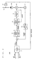
- FIG. 1 is a schematic view showing a configuration of an oil pressure unit 10A according to the embodiment of the present invention.
- the oil pressure unit 10A is connected to a molding machine etc., and supplies oil as working fluid to an actuator (not shown) having the oil pressure as the power source.
- the oil pressure unit 10A includes a controller 20, an inverter unit 14, a motor 15, an oil pressure pump 16A, a pressure sensor 17, and a pulse generator 21.
- the oil is taken in from a tank (not shown) by the oil pressure pump 16A driven by the motor 15, and the oil is discharged.
- the discharged oil is supplied to the actuator such as an oil pressure cylinder or an oil pressure motor through a discharge line 19.
- the pressure sensor 17 serves as a load sensor for detecting the load of the oil pressure pump.
- the pressure sensor 17 also detects the pressure (also referred to as “present pressure” or “load oil pressure”) of the oil in the discharge line 19 of the oil pressure pump.
- the pulse generator 21 serves as a rotation sensor for outputting a pulse signal for detecting the rotation speed of the motor to the controller 20 (speed detection part 22).
- the controller 20 includes a P-Q control part 11, a current command value calculation part 12, a correction part 18A, a control signal generation part 13, and a speed detection part 22.
- the controller 20 outputs a control signal for driving the inverter.
- the P-Q control part 11 generates discharge pressure-discharge flow rate characteristics (P-Q characteristics) based on a set pressure and a set flow rate from a higher level system such as a molding machine.
- the P-Q control part 11 outputs a speed command value based on the present pressure from the pressure sensor 17 as an input.
- the current command value calculation part (also referred to as "PI control part") 12 performs a proportional-integral (PI) control with the speed command value and the current speed as inputs, and outputs a current command value. More specifically, the PI control part 12 calculates the current command value so that the deviation between speed command value representing the target rotation speed of the motor 15 and the rotation speed of the motor 15 converges to zero.
- PI control part also referred to as "PI control part”
- the correction part 18A corrects the current command value based on the present pressure from the pressure sensor 17. The details will be hereinafter described.
- the control signal generation part 13 generates a control signal for controlling the inverter part 14 based on the corrected current command value.
- the correction part 18A will now be described in detail.
- FIG. 2 is a schematic view showing a configuration of a general oil pressure unit 10B.
- the oil pressure unit 10B has the same configuration as the oil pressure unit 10A other than that the correction part 18A is not equipped.
- a high response is demanded on the molding machine to which the oil pressure unit 10B is connected from the standpoint of mass production.
- a stepwise speed command is provided in a short cycle.
- the oil pressure (load oil pressure) in the discharge line 19 of the oil pressure pump 16A becomes larger.
- the load oil pressure becomes larger, the load of the oil pressure pump 16A in discharge increases. That is, the load oil pressure and the load torque of the motor 15 are more or less in a proportional relationship, where the load torque of the motor 15 becomes larger as the mad oil pressure becomes larger.
- the rotation speed of the motor 15 drastically rises in response to the speed command value.
- the load oil pressure drastically increases with rise in rotation speed of the motor 15.
- the load torque drastically becomes larger with an increase in the load oil pressure.
- the speed control by the PI control cannot be followed, and the rotation speed of the motor 15 lowers.
- the followability of the rotation speed of the motor 15 with respect to variation of the load oil pressure can be improved by changing the current command value with variation of the load oil pressure. Furthermore, the lowering in the rotation speed of the motor 15 can be prevented by increasing the current command value with the increase in load oil pressure.
- the correction part 18A for correcting the current command value based on the load oil pressure is equipped.
- the correction value (current correction value) If is acquired using the present pressure (pressure detected value) Pd detected by the pressure sensor 17 and a correction coefficient Kf acquired in advance.
- the correction value If is added to the current command value output from the current command value calculation part 12.
- the current command value is corrected based on the load of the oil pressure pump 16A, that is, the pressure (load oil pressure) of the oil in the discharge line 19. Therefore, the followability of the rotation speed of the motor 15 with respect to the variation of the load (load oil pressure) of the oil pressure pump 16A can be enhanced (improved).
- the coefficient acquired through tests in advance is used as the correction coefficient Kf.
- the correction coefficient Kf is set so that the current command value necessary for preventing lowering in the rotation speed of the motor 15 and following the speed command can be acquired in the correction part 18A.
- the correction coefficient Kf can also be represented as being set so that the lack of current command value necessary for preventing lowering in the rotation speed of the motor 15 and following the speed command can be acquired as the correction value.
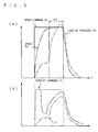
- FIG. 3 is a view showing a state of an operation when a stepwise speed command SC is provided in the oil pressure unit 10A according to the present embodiment.
- the correction value If which value becomes larger with the increase in the load oil pressure Pd1 is acquired in the correction part 18A.
- the correction value If is added to the output from the current command value calculation part 12, and the corrected current command value Ic1 is acquired (see FIG. 3(b) ).
- the current command value Ic1 becomes larger following the increase in the load oil pressure Pd1, and thus the lowering in the rotation speed Rs1 of the motor 15 by the increase in load torque is prevented.
- the rotation speed Rs1 of the motor 15 thus can follow the rotation speed given by the speed command SC.
- FIG. 4 is a view showing a state of an operation when the stepwise speed command SC is provided in the oil pressure unit 10B.
- the magnitude of the current command value is different in zone BT.
- the difference in magnitude of the current command value indicates that the appropriate current command value necessary for following the rotation speed of the motor 15 to the speed command SC is not acquired (calculated) in the oil pressure unit 10B ( FIG. 4(b) ).
- the correction value If that becomes larger with the increase in the load oil pressure Pd is acquired using the load oil pressure Pd detected by the pressure sensor 17 and the correction coefficient Kf previously acquired in the correction part 18A.
- the relevant correction value If is added to the current command value output from the current command value calculation part 12.
- the current command value Ic1 can be increased following the increase in the load oil pressure Pd1 by adding the correction value If acquired based on the load oil pressure Pd1 to the current command value output from the current command value calculation part 12 in a feedforward manner.
- the lowering in the rotation speed Rs1 of the motor 15 by the increase in load torque thus can be prevented.
- FIG. 5 is a schematic view showing an oil pressure unit 10C including a correction part 18B capable of acquiring the correction value If using a data table DT.
- the correction value If may be acquired (calculated) using a data table DT showing a relationship between the load oil pressure (pressure detected value) Pd acquired in advance and the correction value If in the correction part 18B, as shown in FIG. 5 .
- oil pressure unit 10A is driven using one oil pressure pump 16A in the above embodiment, but is not limited thereto.
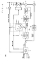
- FIG. 6 is a schematic view showing an oil pressure unit 10D in which two oil pressure pumps 16A, 16B are driven with one motor.
- information (pump drive information) indicating which oil pressure pump is being driven is output to the correction part 18C from the P-Q control part 11 according to the switching of the pump when configuring the oil pressure unit 10D with two oil pressure pumps 16A, 16B.
- the correction part 18C the data table for acquiring the correction value If is switched according to the pump drive information, and the correction value If corresponding to the driven pump is acquired.
- the data table showing a relationship between the load oil pressure (pressure detected value) Pd and the correction value If in a case where the two oil pressure pumps 16A, 16B are simultaneously driven is used to acquire the correction value If.
- FIG. 7 is a schematic view showing an oil pressure unit in which two oil pressure pumps are connected in series. As shown in FIG. 7 , when the two oil pressure pumps are connected in series such that the oil discharged from one oil pressure pump 16B is taken in by the other oil pressure pump 16A, the pressure of the oil discharged form the oil pressure pump 16A on the downstream side is detected by the pressure sensor (17). The current command value is corrected based on the oil pressure discharged by the oil pressure pump 16A on the downstream side.
Abstract
Description
- The present invention relates to an oil pressure unit for driving an oil pressure pump with a motor.
- Conventionally, in an oil pressure unit having an oil pressure pump directly connected to a motor as a drive source, a speed control (PI control) calculation is executed to calculate a current command value through comparison of a speed command value of the motor and a current rotation speed, and a current control based on the current command value is realized by an inverter. The motor controlled by the inverter is then driven so that pressure oil is discharged from the oil pressure pump (e.g., patent document 1).
- Patent document 1: Japanese Laid-Open Patent Publication No.
2004-162860 - In such oil pressure unit, the pressure of oil (oil pressure) becomes larger as a total amount of the oil discharged from the oil pressure pump by a drive of the oil pressure pump increases. An increase in the oil pressure leads to an increase in a load of the oil pressure pump in discharge, and causes a load torque of the motor to become larger.
- Thus, in such oil pressure unit, in a case where a stepwise speed command value is provided, if a rotation speed of the motor drastically rises in response to the speed command value, the load of the oil pressure pump drastically increases and the load torque of the motor drastically becomes large. If the load torque of the motor drastically becomes large, the speed control constituted by the PI control cannot follow, and the rotation speed of the motor might lower.
- A method of preventing lowering of the rotation speed of the motor includes a method of improving a response of the control by shortening a control period of the PI control by improving a processing speed of a microcomputer that performs the PI control. However, a cost of the microcomputer increases if such method is adopted. Furthermore, since the improvement of the processing speed of the microcomputer has physical limitations, lowering in the rotation speed of the motor cannot be effectively prevented with such method.
- Another method includes a method using the load torque for the speed control in which the load torque is estimated from acceleration information obtained by differentiating the rotation speed of the motor. However, since the rotation speed is discrete information, a noise component increases by differentiation. Thus, there is a possibility a behavior will become unstable if the speed control is executed using the load torque.
- Moreover, if a gain of the speed control is increased to improve a response to the load variation, an oscillation might occur when the stepwise speed command value is provided.
- In view of the above problems, it is an object of the present invention to provide a technique capable of improving a followability of the rotation speed of the motor with respect to the variation of the load of the oil pressure pump. Means for Solving the Problems
- A first aspect of an oil pressure unit according to the present invention relates to the oil pressure unit for supplying oil to an actuator by driving an oil pressure pump (16A) with a motor (15), characterized in that it comprises an inverter (14) for supplying power to the motor (15), a load sensor (17) for detecting a load of the oil pressure pump (16A), a rotation sensor (21) for detecting a rotation speed of the motor (15), a current command value calculation means (12) for calculating a current command value so that a deviation between a speed command value representing a target rotation speed of the motor (15) and a rotation speed of the motor (15) converges to zero, a correction means (18A; ··· ; 18D) for correcting the current command value based on the load of the oil pressure pump (16A), and a control signal generation means (13) for outputting a control signal to the inverter (14) based on a corrected current command value.
- According to a second aspect of the oil pressure unit, in the first aspect, it is characterized in that said correction means (18A; ··· ; 18D) corrects the current command value to raise the rotation speed of said motor (15) with an increase in the load of said oil pressure pump (16A).
- According to a third aspect of the oil pressure unit, in the first or the second aspect, it is characterized in that said correction means (18A; ··· ; 18D) increases the current command value with an increase in the load of said oil pressure pump (16A).
- According to a fourth aspect of the oil pressure unit, in any one of the first to the third aspects, it is characterized in that said correction means (18A) acquires a correction value (If) using a correction coefficient (Kf) set in advance, and adds said correction value (If) to said current command value.
- According to a fifth aspect of the oil pressure unit, in any one of the first to the third aspects, it is characterized in that said correction means (18B; 18C; 18D) acquires a correction value (If) using a data table DT acquired in advance, and adds said correction value (If) to said current command value.
- According to a sixth aspect of the oil pressure unit, in any one of the first to the fifth aspects, it is characterized in that said load sensor (17) is a pressure sensor (17) for detecting a pressure of oil in a discharge line (19) of said oil pressure pump (16A).
- A seventh aspect of the oil pressure unit relates to a speed control method of a motor (15) in the oil pressure unit for supplying oil to an actuator by driving an oil pressure pump (16A) with the motor (15) controlled by an inverter (14) and, characterized in that it comprises the steps of: a) detecting a load of said oil pressure pump (16A); b) detecting a rotation speed of said motor (15); c) calculating a current command value so that a deviation between a speed command value representing a target rotation speed of said motor (15) and a rotation speed of said motor (15) converges to zero; d) correcting the current command value based on the load of said oil pressure pump (16A); and e) outputting a control signal to said inverter (14) based on the corrected current command value.
- According to the first aspect to the seventh aspect of the oil pressure unit of the present invention, the followability of the rotation speed of the motor with respect to the variation of the load (load oil pressure) of the oil pressure pump can be improved since the current command value is corrected based on the load of the oil pressure pump.
- In particular, according to the second aspect of the oil pressure unit of the present invention, lowering in rotation speed of the motor involved in an increase of the load of the oil pressure pump can be prevented since the current command value is corrected to raise the rotation speed of the motor with an increase in the load of the oil pressure pump.
- The objects, features, aspects, and advantages of the present invention will become apparent from the following detailed description and the accompanying drawings.
-
- [
FIG. 1 ] It is a schematic view showing a configuration of an oil pressure unit according to an embodiment. - [
FIG. 2 ] It is a schematic view showing a configuration of an oil pressure unit without a correction part. - [
FIG. 3 ] It is a view showing a state of an operation when a stepwise speed command is provided in the oil pressure unit according to the embodiment. - [
FIG. 4 ] It is a view showing a state of an operation when a stepwise speed command is provided in the oil pressure unit oil pressure unit not including a correction part. - [
FIG. 5 ] It is a schematic view showing an oil pressure unit including a correction part capable of acquiring a correction value using a data table. - [
FIG. 6 ] It is a schematic view showing an oil pressure unit in which two oil pressure pumps are driven with one motor. - [
FIG. 7 ] It is a schematic view showing an oil pressure unit in which two oil pressure pumps are connected in series. - An embodiment of the present invention will now be described with reference to the drawings.
-
FIG. 1 is a schematic view showing a configuration of anoil pressure unit 10A according to the embodiment of the present invention. Theoil pressure unit 10A is connected to a molding machine etc., and supplies oil as working fluid to an actuator (not shown) having the oil pressure as the power source. - As shown in
FIG. 1 , theoil pressure unit 10A includes acontroller 20, aninverter unit 14, amotor 15, anoil pressure pump 16A, apressure sensor 17, and apulse generator 21. In theoil pressure unit 10A having such configuration, the oil is taken in from a tank (not shown) by theoil pressure pump 16A driven by themotor 15, and the oil is discharged. The discharged oil is supplied to the actuator such as an oil pressure cylinder or an oil pressure motor through adischarge line 19. - The
pressure sensor 17 serves as a load sensor for detecting the load of the oil pressure pump. Thepressure sensor 17 also detects the pressure (also referred to as "present pressure" or "load oil pressure") of the oil in thedischarge line 19 of the oil pressure pump. - The
pulse generator 21 serves as a rotation sensor for outputting a pulse signal for detecting the rotation speed of the motor to the controller 20 (speed detection part 22). - The
inverter unit 14 controls the rotation number of themotor 15 by performing switching based on a control signal from thecontroller 20. - The
controller 20 includes aP-Q control part 11, a current commandvalue calculation part 12, a correction part 18A, a controlsignal generation part 13, and aspeed detection part 22. Thecontroller 20 outputs a control signal for driving the inverter. - The
P-Q control part 11 generates discharge pressure-discharge flow rate characteristics (P-Q characteristics) based on a set pressure and a set flow rate from a higher level system such as a molding machine. TheP-Q control part 11 outputs a speed command value based on the present pressure from thepressure sensor 17 as an input. - The current command value calculation part (also referred to as "PI control part") 12 performs a proportional-integral (PI) control with the speed command value and the current speed as inputs, and outputs a current command value. More specifically, the
PI control part 12 calculates the current command value so that the deviation between speed command value representing the target rotation speed of themotor 15 and the rotation speed of themotor 15 converges to zero. - The correction part 18A corrects the current command value based on the present pressure from the
pressure sensor 17. The details will be hereinafter described. - The control
signal generation part 13 generates a control signal for controlling theinverter part 14 based on the corrected current command value. - The correction part 18A will now be described in detail.
-
FIG. 2 is a schematic view showing a configuration of a generaloil pressure unit 10B. Theoil pressure unit 10B has the same configuration as theoil pressure unit 10A other than that the correction part 18A is not equipped. - A high response is demanded on the molding machine to which the
oil pressure unit 10B is connected from the standpoint of mass production. Thus, in theoil pressure unit 10B for driving the molding machine, a stepwise speed command is provided in a short cycle. - As the total amount of the oil discharged from the
oil pressure pump 16A increases, the oil pressure (load oil pressure) in thedischarge line 19 of theoil pressure pump 16A becomes larger. As the load oil pressure becomes larger, the load of theoil pressure pump 16A in discharge increases. That is, the load oil pressure and the load torque of themotor 15 are more or less in a proportional relationship, where the load torque of themotor 15 becomes larger as the mad oil pressure becomes larger. - Therefore, in the
oil pressure unit 10B, when the stepwise speed command is provided, the rotation speed of themotor 15 drastically rises in response to the speed command value. The load oil pressure drastically increases with rise in rotation speed of themotor 15. The load torque drastically becomes larger with an increase in the load oil pressure. Thus, the speed control by the PI control cannot be followed, and the rotation speed of themotor 15 lowers. - In order to prevent the lowering in the rotation speed of the
motor 15 by an increase in load torque, the generated torque of themotor 15 needs to become larger with the increase in load torque. The generated torque of themotor 15 and the motor current are in proportional relationship, and thus the motor current, that is, the current command value merely needs to become large for the generated torque of themotor 15 to become large. - In brief, the followability of the rotation speed of the
motor 15 with respect to variation of the load oil pressure can be improved by changing the current command value with variation of the load oil pressure. Furthermore, the lowering in the rotation speed of themotor 15 can be prevented by increasing the current command value with the increase in load oil pressure. - In the
oil pressure unit 10A according to the present embodiment, the correction part 18A for correcting the current command value based on the load oil pressure is equipped. In the correction part 18A, the correction value (current correction value) If is acquired using the present pressure (pressure detected value) Pd detected by thepressure sensor 17 and a correction coefficient Kf acquired in advance. The correction value If is added to the current command value output from the current commandvalue calculation part 12. - According to the correction part 18A, the current command value is corrected based on the load of the
oil pressure pump 16A, that is, the pressure (load oil pressure) of the oil in thedischarge line 19. Therefore, the followability of the rotation speed of themotor 15 with respect to the variation of the load (load oil pressure) of theoil pressure pump 16A can be enhanced (improved). - The coefficient acquired through tests in advance is used as the correction coefficient Kf. Specifically, the correction coefficient Kf is set so that the current command value necessary for preventing lowering in the rotation speed of the
motor 15 and following the speed command can be acquired in the correction part 18A. The correction coefficient Kf can also be represented as being set so that the lack of current command value necessary for preventing lowering in the rotation speed of themotor 15 and following the speed command can be acquired as the correction value. - Through the use of the correction coefficient Kf set so that the lack of the current command value can be acquired as the correction value, the rotation speed of the
motor 15 can be controlled to the rotation speed given by the speed command value. - The correction value If acquired using the correction coefficient Kf becomes larger with rise in load oil pressure. Thus, in the correction part 18A, the current command value can be corrected so as to raise the rotation speed of the
motor 15 with the increase in load oil pressure, and lowering in rotation speed of themotor 15 involved in rise of the load oil pressure is prevented. - The operation in a case where a stepwise speed command SC is provided in the
oil pressure unit 10A will now be specifically described.FIG. 3 is a view showing a state of an operation when a stepwise speed command SC is provided in theoil pressure unit 10A according to the present embodiment. - As shown in
FIG. 3(a) , when the stepwise speed command SC is provided in theoil pressure unit 10A, the rotation speed Rs1 of themotor 15 drastically rises in response to the speed command SC. The pressure Pd1 of the oil discharged from theoil pressure pump 16A then drastically increases, and the load torque of themotor 15 becomes larger. - However, in the
oil pressure unit 10A, the correction value If which value becomes larger with the increase in the load oil pressure Pd1 is acquired in the correction part 18A. The correction value If is added to the output from the current commandvalue calculation part 12, and the corrected current command value Ic1 is acquired (seeFIG. 3(b) ). The current command value Ic1 becomes larger following the increase in the load oil pressure Pd1, and thus the lowering in the rotation speed Rs1 of themotor 15 by the increase in load torque is prevented. The rotation speed Rs1 of themotor 15 thus can follow the rotation speed given by the speed command SC. - There will be compared the operation in a case where the stepwise speed command SC is provided in the
oil pressure unit 10A with the operation in a case where the stepwise speed command SC is provided in theoil pressure unit 10B not including the correction part 18A.FIG. 4 is a view showing a state of an operation when the stepwise speed command SC is provided in theoil pressure unit 10B. - As shown in
FIG. 4(a) , when the stepwise speed command SC is provided in theoil pressure unit 10B, the rotation speed Rs2 of themotor 15 lowers by influence of an increase in the load oil pressure Pd2 due to drastic rise in the rotation speed Rs2 of themotor 15. - Comparing
FIG. 3(b) withFIG. 4(b) , the magnitude of the current command value is different in zone BT. The difference in magnitude of the current command value indicates that the appropriate current command value necessary for following the rotation speed of themotor 15 to the speed command SC is not acquired (calculated) in theoil pressure unit 10B (FIG. 4(b) ). - Therefore, when the rapid speed command like the stepwise speed command SC is provided, the rotation speed of the
motor 15 cannot be followed to such speed command with only the speed control constituted by the PI control. - In the present embodiment, the correction value If that becomes larger with the increase in the load oil pressure Pd is acquired using the load oil pressure Pd detected by the
pressure sensor 17 and the correction coefficient Kf previously acquired in the correction part 18A. The relevant correction value If is added to the current command value output from the current commandvalue calculation part 12. - As described above, the current command value Ic1 can be increased following the increase in the load oil pressure Pd1 by adding the correction value If acquired based on the load oil pressure Pd1 to the current command value output from the current command
value calculation part 12 in a feedforward manner. The lowering in the rotation speed Rs1 of themotor 15 by the increase in load torque thus can be prevented. - The embodiment of the present invention has been described, but the present invention is not limited to the content described above.
- For instance, in the above embodiments, the correction value If is acquired using the correction coefficient Kf previously acquired in the correction part 18A, but is not limited thereto.
FIG. 5 is a schematic view showing anoil pressure unit 10C including a correction part 18B capable of acquiring the correction value If using a data table DT. - Specifically, the correction value If may be acquired (calculated) using a data table DT showing a relationship between the load oil pressure (pressure detected value) Pd acquired in advance and the correction value If in the correction part 18B, as shown in
FIG. 5 . - An appropriate correction value If thus can be acquired with respect to the load pressure Pd from the
pressure sensor 17 even if the load pressure and the correction value necessary for following the speed command are not in a proportional relationship. - Furthermore, the
oil pressure unit 10A is driven using oneoil pressure pump 16A in the above embodiment, but is not limited thereto. - Specifically, the oil pressure unit may be driven using a plurality of oil pressure pumps.
FIG. 6 is a schematic view showing anoil pressure unit 10D in which two oil pressure pumps 16A, 16B are driven with one motor. - For instance, as shown in
FIG. 6 , information (pump drive information) indicating which oil pressure pump is being driven is output to the correction part 18C from theP-Q control part 11 according to the switching of the pump when configuring theoil pressure unit 10D with two oil pressure pumps 16A, 16B. In the correction part 18C, the data table for acquiring the correction value If is switched according to the pump drive information, and the correction value If corresponding to the driven pump is acquired. - When simultaneously driving the two oil pressure pumps 16A, 16B, the data table showing a relationship between the load oil pressure (pressure detected value) Pd and the correction value If in a case where the two oil pressure pumps 16A, 16B are simultaneously driven is used to acquire the correction value If.
- The two oil pressure pumps 16A, 16B do not need be connected in parallel.
FIG. 7 is a schematic view showing an oil pressure unit in which two oil pressure pumps are connected in series. As shown inFIG. 7 , when the two oil pressure pumps are connected in series such that the oil discharged from oneoil pressure pump 16B is taken in by the otheroil pressure pump 16A, the pressure of the oil discharged form theoil pressure pump 16A on the downstream side is detected by the pressure sensor (17). The current command value is corrected based on the oil pressure discharged by theoil pressure pump 16A on the downstream side. - Although the present invention has been described in detail above, the above description is merely illustrative in all aspects and the present invention should not be limited by the description. It should be recognized that an infinite number of modifications that are not illustrated can be contrived without deviating from the scope of the invention.
Claims (13)
- An oil pressure unit for supplying oil to an actuator by driving an oil pressure pump (16A) with a motor (15), the oil pressure unit characterized in that it comprises:an inverter (14) for supplying electric power to said motor (15);a load sensor (17) for detecting a load of said oil pressure pump (16A);a rotation sensor (21) for detecting a rotation speed of said motor (15);a current command value calculation means (12) for calculating a current command value so that a deviation between a speed command value representing a target rotation speed of said motor (15) and a rotation speed of said motor (15) converges to zero;a correction means (18A; ··· ; 18D) for correcting said current command value based on the load of said oil pressure pump; anda control signal generation means (13) for outputting a control signal to said inverter (14) based on a corrected current command value.
- The oil pressure unit according to claim 1, characterized in that said correction means (18A; ··· , 18D) corrects said current command value to raise the rotation speed of said motor (15) with an increase in the load of said oil pressure pump (16A).
- The oil pressure unit according to claim 1 or 2, characterized in that said correction means (18A; ··· ; 18D) increases said current command value with an increase in the load of said oil pressure pump (16A).
- The oil pressure unit according to claim 1 or 2, characterized in that said correction means (18A) acquires a correction value (If) using a correction coefficient (Kf) set in advance, and adds said correction value (If) to said current command value.
- The oil pressure unit according to claim 3, characterized in that said correction means (18A) acquires a correction value (If) using a correction coefficient (Kf) set in advance, and adds said correction value (If) to said current command value.
- The oil pressure unit according to claim 1 or 2, characterized in that said correction means (18B; 18C; 18D) acquires a correction value (If) using a data table DT acquired in advance, and adds said correction value (If) to said current command value.
- The oil pressure unit according to claim 3, characterized in that said correction means (18B; 18C; 18D) acquires a correction value (If) using a data table DT acquired in advance, and adds said correction value (If) to said current command value.
- The oil pressure unit according to claim 1 or 2, characterized in that said load sensor (17) is a pressure sensor (17) for detecting a pressure of oil in a discharge line (19) of said oil pressure pump (16A).
- The oil pressure unit according to claim 3, characterized in that said load sensor (17) is a pressure sensor (17) for detecting a pressure of oil in a discharge line (19) of said oil pressure pump (16A).
- The oil pressure unit according to claim 4, characterized in that said load sensor (17) is a pressure sensor (17) for detecting a pressure of oil in a discharge line (19) of said oil pressure pump (16A).
- The oil pressure unit according to claim 5 or 7, characterized in that said load sensor (17) is a pressure sensor (17) for detecting a pressure of oil in a discharge line (19) of said oil pressure pump (16A).
- The oil pressure unit according to claim 6, characterized in that said load sensor (17) is a pressure sensor (17) for detecting a pressure of oil in a discharge line (19) of said oil pressure pump (16A).
- A speed control method of a motor (15) in an oil pressure unit for supplying oil to an actuator by driving an oil pressure pump (16A) with said motor (15) controlled by an inverter (14), the speed control method characterized in that it comprises the steps of:a) detecting a load of said oil pressure pump (16A);b) detecting a rotation speed of said motor (15);c) calculating a current command value so that a deviation between a speed command value representing a target rotation speed of said motor (15) and a rotation speed of said motor (15) converges to zero;d) correcting said current command value based on the load of said oil pressure pump (16A); ande) outputting a control signal to said inverter (14) based on a corrected current command value.
Applications Claiming Priority (2)
| Application Number | Priority Date | Filing Date | Title |
|---|---|---|---|
| JP2006233529A JP4425253B2 (en) | 2006-08-30 | 2006-08-30 | Hydraulic unit and motor speed control method in hydraulic unit |
| PCT/JP2007/066559 WO2008026544A1 (en) | 2006-08-30 | 2007-08-27 | Hydraulic unit and method of controlling speed of motor in hydraulic unit |
Publications (3)
| Publication Number | Publication Date |
|---|---|
| EP1965083A1 true EP1965083A1 (en) | 2008-09-03 |
| EP1965083A4 EP1965083A4 (en) | 2009-11-11 |
| EP1965083B1 EP1965083B1 (en) | 2011-10-12 |
Family
ID=39135827
Family Applications (1)
| Application Number | Title | Priority Date | Filing Date |
|---|---|---|---|
| EP07806100A Active EP1965083B1 (en) | 2006-08-30 | 2007-08-27 | Hydraulic unit and method of controlling speed of motor in hydraulic unit |
Country Status (7)
| Country | Link |
|---|---|
| US (1) | US20090097986A1 (en) |
| EP (1) | EP1965083B1 (en) |
| JP (1) | JP4425253B2 (en) |
| KR (1) | KR100954697B1 (en) |
| CN (1) | CN101360917B (en) |
| AT (1) | ATE528512T1 (en) |
| WO (1) | WO2008026544A1 (en) |
Cited By (5)
| Publication number | Priority date | Publication date | Assignee | Title |
|---|---|---|---|---|
| WO2011072808A1 (en) * | 2009-12-18 | 2011-06-23 | Robert Bosch Gmbh | Method for operating a hydraulic working machine |
| EP2664968A1 (en) * | 2012-05-16 | 2013-11-20 | Siemens Aktiengesellschaft | Control device for a hydraulic cylinder unit with single valve control |
| FR3005703A1 (en) * | 2013-05-14 | 2014-11-21 | Mach Smart | HYDRAULIC SYSTEM WITH ELECTRONIC CONTROL OF PRESSURE AND FLOW |
| EP3228865A1 (en) * | 2016-04-08 | 2017-10-11 | Jenaer Antriebstechnik GmbH | Method for compensating for cyclic disturbances during the operation of a pump and control unit |
| EP3620656A4 (en) * | 2017-08-28 | 2020-04-01 | Aisin Aw Co., Ltd. | Control device |
Families Citing this family (16)
| Publication number | Priority date | Publication date | Assignee | Title |
|---|---|---|---|---|
| CN101737379B (en) * | 2008-11-21 | 2012-08-29 | 鸿富锦精密工业(深圳)有限公司 | Speed-pressure control device of oil pressure type equipment |
| US8818649B2 (en) * | 2009-06-25 | 2014-08-26 | Hitachi Construction Machinery Co., Ltd. | Rotation control device for working machine |
| KR101095983B1 (en) | 2011-04-19 | 2011-12-19 | 주식회사 하이드텍 | Hydraulic transmission system and method for controlling thereof |
| KR101545677B1 (en) * | 2011-12-16 | 2015-08-19 | 볼보 컨스트럭션 이큅먼트 에이비 | Driver self-tuning method using electro-hydraulic actuator system |
| JP5884481B2 (en) * | 2011-12-28 | 2016-03-15 | 株式会社ジェイテクト | Motor control device and electric pump unit |
| DE102012009136A1 (en) | 2012-05-05 | 2013-11-07 | Robert Bosch Gmbh | Method for operating a fluid pump |
| US9611931B2 (en) | 2012-05-24 | 2017-04-04 | GM Global Technology Operations LLC | Method to detect loss of fluid or blockage in a hydraulic circuit using exponentially weighted moving average filter |
| JP6050081B2 (en) * | 2012-10-05 | 2016-12-21 | 株式会社荏原製作所 | Dry vacuum pump device |
| JP5673768B1 (en) * | 2013-09-27 | 2015-02-18 | ダイキン工業株式会社 | Hydraulic device |
| JP6290602B2 (en) | 2013-11-15 | 2018-03-07 | オークマ株式会社 | Hydraulic control device |
| CN104179736B (en) * | 2014-08-15 | 2016-08-24 | 徐工集团工程机械股份有限公司科技分公司 | A kind of engineering machinery constant displacement pump speed-regulating hydraulic system |
| JP6396733B2 (en) | 2014-09-22 | 2018-09-26 | オークマ株式会社 | Hydraulic control device |
| DE102017117595A1 (en) * | 2017-08-03 | 2019-02-07 | Voith Patent Gmbh | METHOD FOR CONTROLLING THE OUTPUT PRESSURE OF A HYDRAULIC DRIVE SYSTEM, USE OF THE METHOD AND HYDRAULIC DRIVE SYSTEM |
| JP7010906B2 (en) * | 2019-03-20 | 2022-01-26 | ファナック株式会社 | Processing machine and pressure adjustment method |
| DE102020107127A1 (en) | 2019-03-20 | 2020-09-24 | Fanuc Corporation | PROCESSING MACHINE AND PRESSURE ADJUSTMENT METHOD |
| JP7346886B2 (en) * | 2019-04-12 | 2023-09-20 | マックス株式会社 | air compressor |
Citations (5)
| Publication number | Priority date | Publication date | Assignee | Title |
|---|---|---|---|---|
| US5257960A (en) * | 1990-10-31 | 1993-11-02 | Fuji Jukogyo Kabushiki Kaisha | System for controlling a continuously variable |
| US5509788A (en) * | 1993-09-27 | 1996-04-23 | Diversey Corporation | Flow-metered pumping with load compensation system and method |
| JP2001248566A (en) * | 2000-03-02 | 2001-09-14 | Tokimec Inc | Pump rotation speed control system |
| EP1574723A1 (en) * | 2002-11-15 | 2005-09-14 | Daikin Industries, Ltd. | Method and device for controlling temperature rise of autonomous inverter-driven hydraulic unit |
| US20060191262A1 (en) * | 2005-02-28 | 2006-08-31 | Husco International, Inc. | Hydraulic control valve system with electronic load sense control |
Family Cites Families (14)
| Publication number | Priority date | Publication date | Assignee | Title |
|---|---|---|---|---|
| FR2588319B1 (en) * | 1985-10-04 | 1987-12-04 | Milton Roy Dosapro | PROCESS FOR PRECISELY ESTABLISHING THE FLOW RATE OF A METERING PUMP AND METERING PUMP USING THE SAME |
| US4733152A (en) * | 1986-03-10 | 1988-03-22 | Isco, Inc. | Feedback system |
| US5019757A (en) * | 1990-03-19 | 1991-05-28 | General Electric Company | Method and apparatus for controlling a blower motor in an air handling system to provide constant pressure |
| US5141402A (en) * | 1991-01-29 | 1992-08-25 | Vickers, Incorporated | Power transmission |
| JPH07177775A (en) * | 1993-12-20 | 1995-07-14 | Toshiba Corp | Power conversion apparatus controller |
| JP3345311B2 (en) | 1997-08-15 | 2002-11-18 | 川崎製鉄株式会社 | Speed control device of electric motor for rolling mill drive |
| DE19931961A1 (en) * | 1999-07-12 | 2001-02-01 | Danfoss As | Method for controlling a delivery quantity of a pump |
| US6468042B2 (en) * | 1999-07-12 | 2002-10-22 | Danfoss Drives A/S | Method for regulating a delivery variable of a pump |
| US6748739B1 (en) * | 1999-07-14 | 2004-06-15 | Yuken Kogyo Kabushiki Kaisha | Hydraulic power system |
| US6353299B1 (en) * | 1999-10-19 | 2002-03-05 | Fasco Industries, Inc. | Control algorithm for brushless DC motor/blower system |
| DE10162773A1 (en) * | 2001-12-20 | 2003-07-10 | Knf Flodos Ag Sursee | metering |
| US6979181B1 (en) * | 2002-11-27 | 2005-12-27 | Aspen Motion Technologies, Inc. | Method for controlling the motor of a pump involving the determination and synchronization of the point of maximum torque with a table of values used to efficiently drive the motor |
| US7080508B2 (en) * | 2004-05-13 | 2006-07-25 | Itt Manufacturing Enterprises, Inc. | Torque controlled pump protection with mechanical loss compensation |
| DE102005013773A1 (en) * | 2005-03-22 | 2006-09-28 | Diehl Ako Stiftung & Co. Kg | Electronic motor regulation for pump used in e.g. dishwasher, involves detecting and estimating rotor phase position and rotor speed of motor and determining fluctuations in rotor phase position and rotor speed to control pump operation |
-
2006
- 2006-08-30 JP JP2006233529A patent/JP4425253B2/en active Active
-
2007
- 2007-08-27 KR KR1020087013286A patent/KR100954697B1/en not_active IP Right Cessation
- 2007-08-27 US US12/160,003 patent/US20090097986A1/en not_active Abandoned
- 2007-08-27 EP EP07806100A patent/EP1965083B1/en active Active
- 2007-08-27 WO PCT/JP2007/066559 patent/WO2008026544A1/en active Application Filing
- 2007-08-27 CN CN2007800015363A patent/CN101360917B/en active Active
- 2007-08-27 AT AT07806100T patent/ATE528512T1/en active
Patent Citations (5)
| Publication number | Priority date | Publication date | Assignee | Title |
|---|---|---|---|---|
| US5257960A (en) * | 1990-10-31 | 1993-11-02 | Fuji Jukogyo Kabushiki Kaisha | System for controlling a continuously variable |
| US5509788A (en) * | 1993-09-27 | 1996-04-23 | Diversey Corporation | Flow-metered pumping with load compensation system and method |
| JP2001248566A (en) * | 2000-03-02 | 2001-09-14 | Tokimec Inc | Pump rotation speed control system |
| EP1574723A1 (en) * | 2002-11-15 | 2005-09-14 | Daikin Industries, Ltd. | Method and device for controlling temperature rise of autonomous inverter-driven hydraulic unit |
| US20060191262A1 (en) * | 2005-02-28 | 2006-08-31 | Husco International, Inc. | Hydraulic control valve system with electronic load sense control |
Non-Patent Citations (1)
| Title |
|---|
| See also references of WO2008026544A1 * |
Cited By (10)
| Publication number | Priority date | Publication date | Assignee | Title |
|---|---|---|---|---|
| WO2011072808A1 (en) * | 2009-12-18 | 2011-06-23 | Robert Bosch Gmbh | Method for operating a hydraulic working machine |
| CN102782337A (en) * | 2009-12-18 | 2012-11-14 | 罗伯特·博世有限公司 | Method for operating a hydraulic working machine |
| CN102782337B (en) * | 2009-12-18 | 2016-11-09 | 罗伯特·博世有限公司 | For the method running the machine for doing work of hydraulic pressure |
| EP2664968A1 (en) * | 2012-05-16 | 2013-11-20 | Siemens Aktiengesellschaft | Control device for a hydraulic cylinder unit with single valve control |
| WO2013171041A1 (en) * | 2012-05-16 | 2013-11-21 | Siemens Aktiengesellschaft | Control device for a hydraulic cylinder unit with an individual valve controller |
| US9945395B2 (en) | 2012-05-16 | 2018-04-17 | Primetals Technologies Germany Gmbh | Control device for a hydraulic cylinder unit with an individual valve controller |
| FR3005703A1 (en) * | 2013-05-14 | 2014-11-21 | Mach Smart | HYDRAULIC SYSTEM WITH ELECTRONIC CONTROL OF PRESSURE AND FLOW |
| EP3228865A1 (en) * | 2016-04-08 | 2017-10-11 | Jenaer Antriebstechnik GmbH | Method for compensating for cyclic disturbances during the operation of a pump and control unit |
| EP3620656A4 (en) * | 2017-08-28 | 2020-04-01 | Aisin Aw Co., Ltd. | Control device |
| US10955046B2 (en) | 2017-08-28 | 2021-03-23 | Aisin Aw Co., Ltd. | Control device |
Also Published As
| Publication number | Publication date |
|---|---|
| KR20080087084A (en) | 2008-09-30 |
| JP2008057611A (en) | 2008-03-13 |
| CN101360917B (en) | 2011-12-07 |
| ATE528512T1 (en) | 2011-10-15 |
| EP1965083A4 (en) | 2009-11-11 |
| CN101360917A (en) | 2009-02-04 |
| JP4425253B2 (en) | 2010-03-03 |
| US20090097986A1 (en) | 2009-04-16 |
| WO2008026544A1 (en) | 2008-03-06 |
| EP1965083B1 (en) | 2011-10-12 |
| KR100954697B1 (en) | 2010-04-26 |
Similar Documents
| Publication | Publication Date | Title |
|---|---|---|
| EP1965083B1 (en) | Hydraulic unit and method of controlling speed of motor in hydraulic unit | |
| KR101268848B1 (en) | Hybrid construction machine and control method of hybrid construction machine | |
| JP5562870B2 (en) | Hybrid work machine and control method thereof | |
| JP5938901B2 (en) | Motor control device and electric pump unit | |
| KR101875241B1 (en) | Hybrid construction machine | |
| US20160340871A1 (en) | Engine and Pump Control Device and Working Machine | |
| CN106574559B (en) | Excavator | |
| JP2016165985A5 (en) | ||
| JP2013137057A (en) | Motor control device and electric pump unit | |
| JP6136140B2 (en) | Motor control device and electric pump unit | |
| JP2008232445A (en) | Hydraulic unit, and speed control method of motor of hydraulic unit | |
| JP4947655B2 (en) | Engine accelerator value control method and apparatus | |
| CN107250463B (en) | Method for controlling hydraulic pump of construction machine | |
| JP5803874B2 (en) | Hybrid work machine | |
| JP6079032B2 (en) | Motor control device and electric pump unit | |
| EP3112640B1 (en) | Hybrid construction machine | |
| US20220182000A1 (en) | Motor control device, motor drive system, hydraulic pressure generator, motor control method, and storage medium | |
| KR20190085990A (en) | Forklift and fork control method | |
| JP5962008B2 (en) | Motor control device and electric pump unit | |
| JP5212515B2 (en) | Hydraulic unit |
Legal Events
| Date | Code | Title | Description |
|---|---|---|---|
| PUAI | Public reference made under article 153(3) epc to a published international application that has entered the european phase |
Free format text: ORIGINAL CODE: 0009012 |
|
| 17P | Request for examination filed |
Effective date: 20080625 |
|
| AK | Designated contracting states |
Kind code of ref document: A1 Designated state(s): AT BE BG CH CY CZ DE DK EE ES FI FR GB GR HU IE IS IT LI LT LU LV MC MT NL PL PT RO SE SI SK TR |
|
| AX | Request for extension of the european patent |
Extension state: AL BA HR MK RS |
|
| A4 | Supplementary search report drawn up and despatched |
Effective date: 20091014 |
|
| RIC1 | Information provided on ipc code assigned before grant |
Ipc: F15B 11/00 20060101AFI20080408BHEP Ipc: F04B 49/00 20060101ALI20091008BHEP Ipc: F04B 49/06 20060101ALI20091008BHEP Ipc: H02P 27/06 20060101ALI20091008BHEP |
|
| DAX | Request for extension of the european patent (deleted) | ||
| 17Q | First examination report despatched |
Effective date: 20100305 |
|
| GRAP | Despatch of communication of intention to grant a patent |
Free format text: ORIGINAL CODE: EPIDOSNIGR1 |
|
| GRAS | Grant fee paid |
Free format text: ORIGINAL CODE: EPIDOSNIGR3 |
|
| GRAA | (expected) grant |
Free format text: ORIGINAL CODE: 0009210 |
|
| AK | Designated contracting states |
Kind code of ref document: B1 Designated state(s): AT BE BG CH CY CZ DE DK EE ES FI FR GB GR HU IE IS IT LI LT LU LV MC MT NL PL PT RO SE SI SK TR |
|
| REG | Reference to a national code |
Ref country code: GB Ref legal event code: FG4D |
|
| REG | Reference to a national code |
Ref country code: CH Ref legal event code: EP |
|
| REG | Reference to a national code |
Ref country code: IE Ref legal event code: FG4D |
|
| REG | Reference to a national code |
Ref country code: DE Ref legal event code: R096 Ref document number: 602007017847 Country of ref document: DE Effective date: 20120112 |
|
| REG | Reference to a national code |
Ref country code: NL Ref legal event code: VDEP Effective date: 20111012 |
|
| LTIE | Lt: invalidation of european patent or patent extension |
Effective date: 20111012 |
|
| PG25 | Lapsed in a contracting state [announced via postgrant information from national office to epo] |
Ref country code: LT Free format text: LAPSE BECAUSE OF FAILURE TO SUBMIT A TRANSLATION OF THE DESCRIPTION OR TO PAY THE FEE WITHIN THE PRESCRIBED TIME-LIMIT Effective date: 20111012 Ref country code: BE Free format text: LAPSE BECAUSE OF FAILURE TO SUBMIT A TRANSLATION OF THE DESCRIPTION OR TO PAY THE FEE WITHIN THE PRESCRIBED TIME-LIMIT Effective date: 20111012 Ref country code: IS Free format text: LAPSE BECAUSE OF FAILURE TO SUBMIT A TRANSLATION OF THE DESCRIPTION OR TO PAY THE FEE WITHIN THE PRESCRIBED TIME-LIMIT Effective date: 20120212 |
|
| PG25 | Lapsed in a contracting state [announced via postgrant information from national office to epo] |
Ref country code: LV Free format text: LAPSE BECAUSE OF FAILURE TO SUBMIT A TRANSLATION OF THE DESCRIPTION OR TO PAY THE FEE WITHIN THE PRESCRIBED TIME-LIMIT Effective date: 20111012 Ref country code: GR Free format text: LAPSE BECAUSE OF FAILURE TO SUBMIT A TRANSLATION OF THE DESCRIPTION OR TO PAY THE FEE WITHIN THE PRESCRIBED TIME-LIMIT Effective date: 20120113 Ref country code: PT Free format text: LAPSE BECAUSE OF FAILURE TO SUBMIT A TRANSLATION OF THE DESCRIPTION OR TO PAY THE FEE WITHIN THE PRESCRIBED TIME-LIMIT Effective date: 20120213 Ref country code: SI Free format text: LAPSE BECAUSE OF FAILURE TO SUBMIT A TRANSLATION OF THE DESCRIPTION OR TO PAY THE FEE WITHIN THE PRESCRIBED TIME-LIMIT Effective date: 20111012 Ref country code: SE Free format text: LAPSE BECAUSE OF FAILURE TO SUBMIT A TRANSLATION OF THE DESCRIPTION OR TO PAY THE FEE WITHIN THE PRESCRIBED TIME-LIMIT Effective date: 20111012 Ref country code: NL Free format text: LAPSE BECAUSE OF FAILURE TO SUBMIT A TRANSLATION OF THE DESCRIPTION OR TO PAY THE FEE WITHIN THE PRESCRIBED TIME-LIMIT Effective date: 20111012 |
|
| PG25 | Lapsed in a contracting state [announced via postgrant information from national office to epo] |
Ref country code: CY Free format text: LAPSE BECAUSE OF FAILURE TO SUBMIT A TRANSLATION OF THE DESCRIPTION OR TO PAY THE FEE WITHIN THE PRESCRIBED TIME-LIMIT Effective date: 20111012 |
|
| PG25 | Lapsed in a contracting state [announced via postgrant information from national office to epo] |
Ref country code: BG Free format text: LAPSE BECAUSE OF FAILURE TO SUBMIT A TRANSLATION OF THE DESCRIPTION OR TO PAY THE FEE WITHIN THE PRESCRIBED TIME-LIMIT Effective date: 20120112 Ref country code: DK Free format text: LAPSE BECAUSE OF FAILURE TO SUBMIT A TRANSLATION OF THE DESCRIPTION OR TO PAY THE FEE WITHIN THE PRESCRIBED TIME-LIMIT Effective date: 20111012 Ref country code: CZ Free format text: LAPSE BECAUSE OF FAILURE TO SUBMIT A TRANSLATION OF THE DESCRIPTION OR TO PAY THE FEE WITHIN THE PRESCRIBED TIME-LIMIT Effective date: 20111012 Ref country code: EE Free format text: LAPSE BECAUSE OF FAILURE TO SUBMIT A TRANSLATION OF THE DESCRIPTION OR TO PAY THE FEE WITHIN THE PRESCRIBED TIME-LIMIT Effective date: 20111012 Ref country code: SK Free format text: LAPSE BECAUSE OF FAILURE TO SUBMIT A TRANSLATION OF THE DESCRIPTION OR TO PAY THE FEE WITHIN THE PRESCRIBED TIME-LIMIT Effective date: 20111012 |
|
| PLBE | No opposition filed within time limit |
Free format text: ORIGINAL CODE: 0009261 |
|
| STAA | Information on the status of an ep patent application or granted ep patent |
Free format text: STATUS: NO OPPOSITION FILED WITHIN TIME LIMIT |
|
| PG25 | Lapsed in a contracting state [announced via postgrant information from national office to epo] |
Ref country code: PL Free format text: LAPSE BECAUSE OF FAILURE TO SUBMIT A TRANSLATION OF THE DESCRIPTION OR TO PAY THE FEE WITHIN THE PRESCRIBED TIME-LIMIT Effective date: 20111012 Ref country code: RO Free format text: LAPSE BECAUSE OF FAILURE TO SUBMIT A TRANSLATION OF THE DESCRIPTION OR TO PAY THE FEE WITHIN THE PRESCRIBED TIME-LIMIT Effective date: 20111012 |
|
| 26N | No opposition filed |
Effective date: 20120713 |
|
| REG | Reference to a national code |
Ref country code: DE Ref legal event code: R097 Ref document number: 602007017847 Country of ref document: DE Effective date: 20120713 |
|
| REG | Reference to a national code |
Ref country code: CH Ref legal event code: PL |
|
| PG25 | Lapsed in a contracting state [announced via postgrant information from national office to epo] |
Ref country code: MC Free format text: LAPSE BECAUSE OF NON-PAYMENT OF DUE FEES Effective date: 20120831 |
|
| PG25 | Lapsed in a contracting state [announced via postgrant information from national office to epo] |
Ref country code: CH Free format text: LAPSE BECAUSE OF NON-PAYMENT OF DUE FEES Effective date: 20120831 Ref country code: LI Free format text: LAPSE BECAUSE OF NON-PAYMENT OF DUE FEES Effective date: 20120831 |
|
| REG | Reference to a national code |
Ref country code: FR Ref legal event code: ST Effective date: 20130430 |
|
| REG | Reference to a national code |
Ref country code: IE Ref legal event code: MM4A |
|
| PG25 | Lapsed in a contracting state [announced via postgrant information from national office to epo] |
Ref country code: FI Free format text: LAPSE BECAUSE OF FAILURE TO SUBMIT A TRANSLATION OF THE DESCRIPTION OR TO PAY THE FEE WITHIN THE PRESCRIBED TIME-LIMIT Effective date: 20111012 |
|
| PG25 | Lapsed in a contracting state [announced via postgrant information from national office to epo] |
Ref country code: IE Free format text: LAPSE BECAUSE OF NON-PAYMENT OF DUE FEES Effective date: 20120827 |
|
| PG25 | Lapsed in a contracting state [announced via postgrant information from national office to epo] |
Ref country code: FR Free format text: LAPSE BECAUSE OF NON-PAYMENT OF DUE FEES Effective date: 20120831 |
|
| PG25 | Lapsed in a contracting state [announced via postgrant information from national office to epo] |
Ref country code: ES Free format text: LAPSE BECAUSE OF FAILURE TO SUBMIT A TRANSLATION OF THE DESCRIPTION OR TO PAY THE FEE WITHIN THE PRESCRIBED TIME-LIMIT Effective date: 20120123 |
|
| PGFP | Annual fee paid to national office [announced via postgrant information from national office to epo] |
Ref country code: AT Payment date: 20130726 Year of fee payment: 7 |
|
| PG25 | Lapsed in a contracting state [announced via postgrant information from national office to epo] |
Ref country code: MT Free format text: LAPSE BECAUSE OF FAILURE TO SUBMIT A TRANSLATION OF THE DESCRIPTION OR TO PAY THE FEE WITHIN THE PRESCRIBED TIME-LIMIT Effective date: 20111012 |
|
| PG25 | Lapsed in a contracting state [announced via postgrant information from national office to epo] |
Ref country code: TR Free format text: LAPSE BECAUSE OF FAILURE TO SUBMIT A TRANSLATION OF THE DESCRIPTION OR TO PAY THE FEE WITHIN THE PRESCRIBED TIME-LIMIT Effective date: 20111012 |
|
| PG25 | Lapsed in a contracting state [announced via postgrant information from national office to epo] |
Ref country code: LU Free format text: LAPSE BECAUSE OF NON-PAYMENT OF DUE FEES Effective date: 20120827 |
|
| PG25 | Lapsed in a contracting state [announced via postgrant information from national office to epo] |
Ref country code: HU Free format text: LAPSE BECAUSE OF FAILURE TO SUBMIT A TRANSLATION OF THE DESCRIPTION OR TO PAY THE FEE WITHIN THE PRESCRIBED TIME-LIMIT Effective date: 20070827 |
|
| REG | Reference to a national code |
Ref country code: AT Ref legal event code: MM01 Ref document number: 528512 Country of ref document: AT Kind code of ref document: T Effective date: 20140827 |
|
| PG25 | Lapsed in a contracting state [announced via postgrant information from national office to epo] |
Ref country code: AT Free format text: LAPSE BECAUSE OF NON-PAYMENT OF DUE FEES Effective date: 20140827 |
|
| P01 | Opt-out of the competence of the unified patent court (upc) registered |
Effective date: 20230525 |
|
| PGFP | Annual fee paid to national office [announced via postgrant information from national office to epo] |
Ref country code: IT Payment date: 20230711 Year of fee payment: 17 Ref country code: GB Payment date: 20230706 Year of fee payment: 17 |
|
| PGFP | Annual fee paid to national office [announced via postgrant information from national office to epo] |
Ref country code: DE Payment date: 20230703 Year of fee payment: 17 |