EP1966108B1 - Controlled pore size distribution porous ceramic honeycomb filter - Google Patents
Controlled pore size distribution porous ceramic honeycomb filter Download PDFInfo
- Publication number
- EP1966108B1 EP1966108B1 EP06844303A EP06844303A EP1966108B1 EP 1966108 B1 EP1966108 B1 EP 1966108B1 EP 06844303 A EP06844303 A EP 06844303A EP 06844303 A EP06844303 A EP 06844303A EP 1966108 B1 EP1966108 B1 EP 1966108B1
- Authority
- EP
- European Patent Office
- Prior art keywords
- pore
- porous ceramic
- pore size
- starch
- ceramic honeycomb
- Prior art date
- Legal status (The legal status is an assumption and is not a legal conclusion. Google has not performed a legal analysis and makes no representation as to the accuracy of the status listed.)
- Active
Links
- 239000011148 porous material Substances 0.000 title claims abstract description 189
- 238000009826 distribution Methods 0.000 title claims abstract description 70
- 239000000919 ceramic Substances 0.000 title claims abstract description 45
- 229920002472 Starch Polymers 0.000 claims abstract description 53
- 235000019698 starch Nutrition 0.000 claims abstract description 53
- 239000008107 starch Substances 0.000 claims abstract description 44
- 239000000463 material Substances 0.000 claims abstract description 39
- 229910052878 cordierite Inorganic materials 0.000 claims abstract description 28
- JSKIRARMQDRGJZ-UHFFFAOYSA-N dimagnesium dioxido-bis[(1-oxido-3-oxo-2,4,6,8,9-pentaoxa-1,3-disila-5,7-dialuminabicyclo[3.3.1]nonan-7-yl)oxy]silane Chemical compound [Mg++].[Mg++].[O-][Si]([O-])(O[Al]1O[Al]2O[Si](=O)O[Si]([O-])(O1)O2)O[Al]1O[Al]2O[Si](=O)O[Si]([O-])(O1)O2 JSKIRARMQDRGJZ-UHFFFAOYSA-N 0.000 claims abstract description 28
- 229910000505 Al2TiO5 Inorganic materials 0.000 claims abstract description 16
- 240000004922 Vigna radiata Species 0.000 claims abstract description 15
- AABBHSMFGKYLKE-SNAWJCMRSA-N propan-2-yl (e)-but-2-enoate Chemical compound C\C=C\C(=O)OC(C)C AABBHSMFGKYLKE-SNAWJCMRSA-N 0.000 claims abstract description 15
- 235000010721 Vigna radiata var radiata Nutrition 0.000 claims abstract description 14
- 235000005273 Canna coccinea Nutrition 0.000 claims abstract description 13
- 235000011469 Vigna radiata var sublobata Nutrition 0.000 claims abstract description 13
- 235000000378 Caryota urens Nutrition 0.000 claims abstract description 10
- 235000008601 Cycas revoluta Nutrition 0.000 claims abstract description 10
- 235000010103 Metroxylon rumphii Nutrition 0.000 claims abstract description 10
- 229920001592 potato starch Polymers 0.000 claims abstract description 10
- 229910010293 ceramic material Inorganic materials 0.000 claims abstract description 6
- 240000008555 Canna flaccida Species 0.000 claims abstract 2
- 240000000163 Cycas revoluta Species 0.000 claims abstract 2
- 239000002245 particle Substances 0.000 abstract description 41
- VYPSYNLAJGMNEJ-UHFFFAOYSA-N Silicium dioxide Chemical compound O=[Si]=O VYPSYNLAJGMNEJ-UHFFFAOYSA-N 0.000 abstract description 19
- 239000000203 mixture Substances 0.000 abstract description 18
- PNEYBMLMFCGWSK-UHFFFAOYSA-N aluminium oxide Inorganic materials [O-2].[O-2].[O-2].[Al+3].[Al+3] PNEYBMLMFCGWSK-UHFFFAOYSA-N 0.000 abstract description 8
- 238000000034 method Methods 0.000 abstract description 8
- 239000000377 silicon dioxide Substances 0.000 abstract description 6
- CPLXHLVBOLITMK-UHFFFAOYSA-N Magnesium oxide Chemical compound [Mg]=O CPLXHLVBOLITMK-UHFFFAOYSA-N 0.000 abstract description 4
- 239000000395 magnesium oxide Substances 0.000 abstract description 2
- 210000004027 cell Anatomy 0.000 description 22
- 238000001914 filtration Methods 0.000 description 12
- 239000004071 soot Substances 0.000 description 12
- 244000292211 Canna coccinea Species 0.000 description 11
- 239000002994 raw material Substances 0.000 description 11
- 241000346092 Metroxylon Species 0.000 description 9
- 210000002421 cell wall Anatomy 0.000 description 9
- QSHDDOUJBYECFT-UHFFFAOYSA-N mercury Chemical compound [Hg] QSHDDOUJBYECFT-UHFFFAOYSA-N 0.000 description 7
- 229910052753 mercury Inorganic materials 0.000 description 7
- 238000010304 firing Methods 0.000 description 6
- 239000011777 magnesium Substances 0.000 description 6
- 239000000454 talc Substances 0.000 description 6
- 229910052623 talc Inorganic materials 0.000 description 6
- 239000005995 Aluminium silicate Substances 0.000 description 5
- OKTJSMMVPCPJKN-UHFFFAOYSA-N Carbon Chemical compound [C] OKTJSMMVPCPJKN-UHFFFAOYSA-N 0.000 description 5
- GWEVSGVZZGPLCZ-UHFFFAOYSA-N Titan oxide Chemical compound O=[Ti]=O GWEVSGVZZGPLCZ-UHFFFAOYSA-N 0.000 description 5
- 235000012211 aluminium silicate Nutrition 0.000 description 5
- 230000008901 benefit Effects 0.000 description 5
- 230000001747 exhibiting effect Effects 0.000 description 5
- NLYAJNPCOHFWQQ-UHFFFAOYSA-N kaolin Chemical compound O.O.O=[Al]O[Si](=O)O[Si](=O)O[Al]=O NLYAJNPCOHFWQQ-UHFFFAOYSA-N 0.000 description 5
- 239000004033 plastic Substances 0.000 description 5
- 238000002459 porosimetry Methods 0.000 description 5
- 239000003054 catalyst Substances 0.000 description 4
- 239000004927 clay Substances 0.000 description 4
- 239000011248 coating agent Substances 0.000 description 4
- 238000000576 coating method Methods 0.000 description 4
- 238000001035 drying Methods 0.000 description 4
- 239000010439 graphite Substances 0.000 description 4
- 229910002804 graphite Inorganic materials 0.000 description 4
- XEEYBQQBJWHFJM-UHFFFAOYSA-N iron Substances [Fe] XEEYBQQBJWHFJM-UHFFFAOYSA-N 0.000 description 4
- 238000004519 manufacturing process Methods 0.000 description 4
- 235000012239 silicon dioxide Nutrition 0.000 description 4
- 239000002904 solvent Substances 0.000 description 4
- 239000011230 binding agent Substances 0.000 description 3
- 229910052799 carbon Inorganic materials 0.000 description 3
- 230000001413 cellular effect Effects 0.000 description 3
- 235000013339 cereals Nutrition 0.000 description 3
- 238000001125 extrusion Methods 0.000 description 3
- PXHVJJICTQNCMI-UHFFFAOYSA-N nickel Substances [Ni] PXHVJJICTQNCMI-UHFFFAOYSA-N 0.000 description 3
- 239000010453 quartz Substances 0.000 description 3
- 230000035939 shock Effects 0.000 description 3
- HBMJWWWQQXIZIP-UHFFFAOYSA-N silicon carbide Chemical compound [Si+]#[C-] HBMJWWWQQXIZIP-UHFFFAOYSA-N 0.000 description 3
- 238000006467 substitution reaction Methods 0.000 description 3
- XLYOFNOQVPJJNP-UHFFFAOYSA-N water Substances O XLYOFNOQVPJJNP-UHFFFAOYSA-N 0.000 description 3
- VTYYLEPIZMXCLO-UHFFFAOYSA-L Calcium carbonate Chemical compound [Ca+2].[O-]C([O-])=O VTYYLEPIZMXCLO-UHFFFAOYSA-L 0.000 description 2
- 240000004713 Pisum sativum Species 0.000 description 2
- 235000016816 Pisum sativum subsp sativum Nutrition 0.000 description 2
- 244000061456 Solanum tuberosum Species 0.000 description 2
- 235000002595 Solanum tuberosum Nutrition 0.000 description 2
- 229910052782 aluminium Inorganic materials 0.000 description 2
- XAGFODPZIPBFFR-UHFFFAOYSA-N aluminium Chemical compound [Al] XAGFODPZIPBFFR-UHFFFAOYSA-N 0.000 description 2
- WNROFYMDJYEPJX-UHFFFAOYSA-K aluminium hydroxide Chemical compound [OH-].[OH-].[OH-].[Al+3] WNROFYMDJYEPJX-UHFFFAOYSA-K 0.000 description 2
- 239000003795 chemical substances by application Substances 0.000 description 2
- 238000005336 cracking Methods 0.000 description 2
- 239000013078 crystal Substances 0.000 description 2
- 230000001186 cumulative effect Effects 0.000 description 2
- 235000013312 flour Nutrition 0.000 description 2
- 238000010438 heat treatment Methods 0.000 description 2
- 239000004615 ingredient Substances 0.000 description 2
- 229910052751 metal Inorganic materials 0.000 description 2
- 239000002184 metal Substances 0.000 description 2
- 229920000609 methyl cellulose Polymers 0.000 description 2
- 239000001923 methylcellulose Substances 0.000 description 2
- 235000010981 methylcellulose Nutrition 0.000 description 2
- 238000001000 micrograph Methods 0.000 description 2
- 230000003647 oxidation Effects 0.000 description 2
- 238000007254 oxidation reaction Methods 0.000 description 2
- 239000011236 particulate material Substances 0.000 description 2
- 230000008569 process Effects 0.000 description 2
- 238000012545 processing Methods 0.000 description 2
- 230000009467 reduction Effects 0.000 description 2
- 229910010271 silicon carbide Inorganic materials 0.000 description 2
- 239000000758 substrate Substances 0.000 description 2
- 229920000856 Amylose Polymers 0.000 description 1
- 241000233788 Arecaceae Species 0.000 description 1
- 241000202778 Arenga Species 0.000 description 1
- 235000012430 Arenga Nutrition 0.000 description 1
- 241001299965 Borassus Species 0.000 description 1
- 235000006519 Borassus Nutrition 0.000 description 1
- 241000592295 Cycadophyta Species 0.000 description 1
- 241000218916 Cycas Species 0.000 description 1
- GYHNNYVSQQEPJS-UHFFFAOYSA-N Gallium Chemical compound [Ga] GYHNNYVSQQEPJS-UHFFFAOYSA-N 0.000 description 1
- FYYHWMGAXLPEAU-UHFFFAOYSA-N Magnesium Chemical compound [Mg] FYYHWMGAXLPEAU-UHFFFAOYSA-N 0.000 description 1
- PWHULOQIROXLJO-UHFFFAOYSA-N Manganese Chemical compound [Mn] PWHULOQIROXLJO-UHFFFAOYSA-N 0.000 description 1
- 229920003091 Methocel™ Polymers 0.000 description 1
- 240000007817 Olea europaea Species 0.000 description 1
- 244000046052 Phaseolus vulgaris Species 0.000 description 1
- 235000010627 Phaseolus vulgaris Nutrition 0.000 description 1
- 235000006582 Vigna radiata Nutrition 0.000 description 1
- 229910021536 Zeolite Inorganic materials 0.000 description 1
- YKTSYUJCYHOUJP-UHFFFAOYSA-N [O--].[Al+3].[Al+3].[O-][Si]([O-])([O-])[O-] Chemical compound [O--].[Al+3].[Al+3].[O-][Si]([O-])([O-])[O-] YKTSYUJCYHOUJP-UHFFFAOYSA-N 0.000 description 1
- 239000003513 alkali Substances 0.000 description 1
- 229910052784 alkaline earth metal Inorganic materials 0.000 description 1
- 150000001342 alkaline earth metals Chemical class 0.000 description 1
- RREGISFBPQOLTM-UHFFFAOYSA-N alumane;trihydrate Chemical compound O.O.O.[AlH3] RREGISFBPQOLTM-UHFFFAOYSA-N 0.000 description 1
- 229910021502 aluminium hydroxide Inorganic materials 0.000 description 1
- 230000009286 beneficial effect Effects 0.000 description 1
- 229910001593 boehmite Inorganic materials 0.000 description 1
- 229910000019 calcium carbonate Inorganic materials 0.000 description 1
- 230000008859 change Effects 0.000 description 1
- 238000006243 chemical reaction Methods 0.000 description 1
- 229910017052 cobalt Inorganic materials 0.000 description 1
- 239000010941 cobalt Substances 0.000 description 1
- GUTLYIVDDKVIGB-UHFFFAOYSA-N cobalt atom Chemical compound [Co] GUTLYIVDDKVIGB-UHFFFAOYSA-N 0.000 description 1
- 238000002485 combustion reaction Methods 0.000 description 1
- 239000000470 constituent Substances 0.000 description 1
- 238000005314 correlation function Methods 0.000 description 1
- 229910052906 cristobalite Inorganic materials 0.000 description 1
- 229910002026 crystalline silica Inorganic materials 0.000 description 1
- 230000001627 detrimental effect Effects 0.000 description 1
- 238000007571 dilatometry Methods 0.000 description 1
- HNPSIPDUKPIQMN-UHFFFAOYSA-N dioxosilane;oxo(oxoalumanyloxy)alumane Chemical compound O=[Si]=O.O=[Al]O[Al]=O HNPSIPDUKPIQMN-UHFFFAOYSA-N 0.000 description 1
- 230000008030 elimination Effects 0.000 description 1
- 238000003379 elimination reaction Methods 0.000 description 1
- 230000007613 environmental effect Effects 0.000 description 1
- 239000000446 fuel Substances 0.000 description 1
- 239000005350 fused silica glass Substances 0.000 description 1
- 229910052733 gallium Inorganic materials 0.000 description 1
- 229910052732 germanium Inorganic materials 0.000 description 1
- GNPVGFCGXDBREM-UHFFFAOYSA-N germanium atom Chemical compound [Ge] GNPVGFCGXDBREM-UHFFFAOYSA-N 0.000 description 1
- 229910001679 gibbsite Inorganic materials 0.000 description 1
- FAHBNUUHRFUEAI-UHFFFAOYSA-M hydroxidooxidoaluminium Chemical compound O[Al]=O FAHBNUUHRFUEAI-UHFFFAOYSA-M 0.000 description 1
- 238000010348 incorporation Methods 0.000 description 1
- 229910010272 inorganic material Inorganic materials 0.000 description 1
- 239000011147 inorganic material Substances 0.000 description 1
- 229910052742 iron Inorganic materials 0.000 description 1
- 229910052747 lanthanoid Inorganic materials 0.000 description 1
- 150000002602 lanthanoids Chemical class 0.000 description 1
- MRELNEQAGSRDBK-UHFFFAOYSA-N lanthanum oxide Inorganic materials [O-2].[O-2].[O-2].[La+3].[La+3] MRELNEQAGSRDBK-UHFFFAOYSA-N 0.000 description 1
- 239000000314 lubricant Substances 0.000 description 1
- 229910052749 magnesium Inorganic materials 0.000 description 1
- HCWCAKKEBCNQJP-UHFFFAOYSA-N magnesium orthosilicate Chemical compound [Mg+2].[Mg+2].[O-][Si]([O-])([O-])[O-] HCWCAKKEBCNQJP-UHFFFAOYSA-N 0.000 description 1
- 239000000391 magnesium silicate Substances 0.000 description 1
- 229910052919 magnesium silicate Inorganic materials 0.000 description 1
- 235000019792 magnesium silicate Nutrition 0.000 description 1
- 229910052748 manganese Inorganic materials 0.000 description 1
- 239000011572 manganese Substances 0.000 description 1
- 238000005259 measurement Methods 0.000 description 1
- 238000002156 mixing Methods 0.000 description 1
- 229910052759 nickel Inorganic materials 0.000 description 1
- 235000012149 noodles Nutrition 0.000 description 1
- 239000011368 organic material Substances 0.000 description 1
- TWNQGVIAIRXVLR-UHFFFAOYSA-N oxo(oxoalumanyloxy)alumane Chemical compound O=[Al]O[Al]=O TWNQGVIAIRXVLR-UHFFFAOYSA-N 0.000 description 1
- KTUFCUMIWABKDW-UHFFFAOYSA-N oxo(oxolanthaniooxy)lanthanum Chemical compound O=[La]O[La]=O KTUFCUMIWABKDW-UHFFFAOYSA-N 0.000 description 1
- 230000035699 permeability Effects 0.000 description 1
- 239000004014 plasticizer Substances 0.000 description 1
- 239000000843 powder Substances 0.000 description 1
- 229910052761 rare earth metal Inorganic materials 0.000 description 1
- 150000002910 rare earth metals Chemical class 0.000 description 1
- 229910052706 scandium Inorganic materials 0.000 description 1
- SIXSYDAISGFNSX-UHFFFAOYSA-N scandium atom Chemical compound [Sc] SIXSYDAISGFNSX-UHFFFAOYSA-N 0.000 description 1
- 229910052710 silicon Inorganic materials 0.000 description 1
- 239000010703 silicon Substances 0.000 description 1
- RYYKJJJTJZKILX-UHFFFAOYSA-M sodium octadecanoate Chemical compound [Na+].CCCCCCCCCCCCCCCCCC([O-])=O RYYKJJJTJZKILX-UHFFFAOYSA-M 0.000 description 1
- 229910001220 stainless steel Inorganic materials 0.000 description 1
- 239000010935 stainless steel Substances 0.000 description 1
- 229910000018 strontium carbonate Inorganic materials 0.000 description 1
- LEDMRZGFZIAGGB-UHFFFAOYSA-L strontium carbonate Chemical compound [Sr+2].[O-]C([O-])=O LEDMRZGFZIAGGB-UHFFFAOYSA-L 0.000 description 1
- 239000000126 substance Substances 0.000 description 1
- 239000000725 suspension Substances 0.000 description 1
- 230000007704 transition Effects 0.000 description 1
- 238000009834 vaporization Methods 0.000 description 1
- 230000008016 vaporization Effects 0.000 description 1
- 238000005303 weighing Methods 0.000 description 1
- 229910052727 yttrium Inorganic materials 0.000 description 1
- VWQVUPCCIRVNHF-UHFFFAOYSA-N yttrium atom Chemical compound [Y] VWQVUPCCIRVNHF-UHFFFAOYSA-N 0.000 description 1
- 239000010457 zeolite Substances 0.000 description 1
Images


Classifications
-
- C—CHEMISTRY; METALLURGY
- C04—CEMENTS; CONCRETE; ARTIFICIAL STONE; CERAMICS; REFRACTORIES
- C04B—LIME, MAGNESIA; SLAG; CEMENTS; COMPOSITIONS THEREOF, e.g. MORTARS, CONCRETE OR LIKE BUILDING MATERIALS; ARTIFICIAL STONE; CERAMICS; REFRACTORIES; TREATMENT OF NATURAL STONE
- C04B38/00—Porous mortars, concrete, artificial stone or ceramic ware; Preparation thereof
- C04B38/0006—Honeycomb structures
-
- B—PERFORMING OPERATIONS; TRANSPORTING
- B01—PHYSICAL OR CHEMICAL PROCESSES OR APPARATUS IN GENERAL
- B01D—SEPARATION
- B01D39/00—Filtering material for liquid or gaseous fluids
- B01D39/14—Other self-supporting filtering material ; Other filtering material
- B01D39/20—Other self-supporting filtering material ; Other filtering material of inorganic material, e.g. asbestos paper, metallic filtering material of non-woven wires
- B01D39/2068—Other inorganic materials, e.g. ceramics
-
- C—CHEMISTRY; METALLURGY
- C04—CEMENTS; CONCRETE; ARTIFICIAL STONE; CERAMICS; REFRACTORIES
- C04B—LIME, MAGNESIA; SLAG; CEMENTS; COMPOSITIONS THEREOF, e.g. MORTARS, CONCRETE OR LIKE BUILDING MATERIALS; ARTIFICIAL STONE; CERAMICS; REFRACTORIES; TREATMENT OF NATURAL STONE
- C04B35/00—Shaped ceramic products characterised by their composition; Ceramics compositions; Processing powders of inorganic compounds preparatory to the manufacturing of ceramic products
- C04B35/01—Shaped ceramic products characterised by their composition; Ceramics compositions; Processing powders of inorganic compounds preparatory to the manufacturing of ceramic products based on oxide ceramics
- C04B35/16—Shaped ceramic products characterised by their composition; Ceramics compositions; Processing powders of inorganic compounds preparatory to the manufacturing of ceramic products based on oxide ceramics based on silicates other than clay
- C04B35/18—Shaped ceramic products characterised by their composition; Ceramics compositions; Processing powders of inorganic compounds preparatory to the manufacturing of ceramic products based on oxide ceramics based on silicates other than clay rich in aluminium oxide
- C04B35/195—Alkaline earth aluminosilicates, e.g. cordierite or anorthite
-
- C—CHEMISTRY; METALLURGY
- C04—CEMENTS; CONCRETE; ARTIFICIAL STONE; CERAMICS; REFRACTORIES
- C04B—LIME, MAGNESIA; SLAG; CEMENTS; COMPOSITIONS THEREOF, e.g. MORTARS, CONCRETE OR LIKE BUILDING MATERIALS; ARTIFICIAL STONE; CERAMICS; REFRACTORIES; TREATMENT OF NATURAL STONE
- C04B35/00—Shaped ceramic products characterised by their composition; Ceramics compositions; Processing powders of inorganic compounds preparatory to the manufacturing of ceramic products
- C04B35/01—Shaped ceramic products characterised by their composition; Ceramics compositions; Processing powders of inorganic compounds preparatory to the manufacturing of ceramic products based on oxide ceramics
- C04B35/46—Shaped ceramic products characterised by their composition; Ceramics compositions; Processing powders of inorganic compounds preparatory to the manufacturing of ceramic products based on oxide ceramics based on titanium oxides or titanates
- C04B35/462—Shaped ceramic products characterised by their composition; Ceramics compositions; Processing powders of inorganic compounds preparatory to the manufacturing of ceramic products based on oxide ceramics based on titanium oxides or titanates based on titanates
- C04B35/478—Shaped ceramic products characterised by their composition; Ceramics compositions; Processing powders of inorganic compounds preparatory to the manufacturing of ceramic products based on oxide ceramics based on titanium oxides or titanates based on titanates based on aluminium titanates
-
- C—CHEMISTRY; METALLURGY
- C04—CEMENTS; CONCRETE; ARTIFICIAL STONE; CERAMICS; REFRACTORIES
- C04B—LIME, MAGNESIA; SLAG; CEMENTS; COMPOSITIONS THEREOF, e.g. MORTARS, CONCRETE OR LIKE BUILDING MATERIALS; ARTIFICIAL STONE; CERAMICS; REFRACTORIES; TREATMENT OF NATURAL STONE
- C04B38/00—Porous mortars, concrete, artificial stone or ceramic ware; Preparation thereof
- C04B38/0006—Honeycomb structures
- C04B38/0012—Honeycomb structures characterised by the material used for sealing or plugging (some of) the channels of the honeycombs
-
- B—PERFORMING OPERATIONS; TRANSPORTING
- B01—PHYSICAL OR CHEMICAL PROCESSES OR APPARATUS IN GENERAL
- B01D—SEPARATION
- B01D2239/00—Aspects relating to filtering material for liquid or gaseous fluids
- B01D2239/10—Filtering material manufacturing
-
- C—CHEMISTRY; METALLURGY
- C04—CEMENTS; CONCRETE; ARTIFICIAL STONE; CERAMICS; REFRACTORIES
- C04B—LIME, MAGNESIA; SLAG; CEMENTS; COMPOSITIONS THEREOF, e.g. MORTARS, CONCRETE OR LIKE BUILDING MATERIALS; ARTIFICIAL STONE; CERAMICS; REFRACTORIES; TREATMENT OF NATURAL STONE
- C04B2111/00—Mortars, concrete or artificial stone or mixtures to prepare them, characterised by specific function, property or use
- C04B2111/00034—Physico-chemical characteristics of the mixtures
- C04B2111/00129—Extrudable mixtures
-
- C—CHEMISTRY; METALLURGY
- C04—CEMENTS; CONCRETE; ARTIFICIAL STONE; CERAMICS; REFRACTORIES
- C04B—LIME, MAGNESIA; SLAG; CEMENTS; COMPOSITIONS THEREOF, e.g. MORTARS, CONCRETE OR LIKE BUILDING MATERIALS; ARTIFICIAL STONE; CERAMICS; REFRACTORIES; TREATMENT OF NATURAL STONE
- C04B2111/00—Mortars, concrete or artificial stone or mixtures to prepare them, characterised by specific function, property or use
- C04B2111/00474—Uses not provided for elsewhere in C04B2111/00
- C04B2111/00793—Uses not provided for elsewhere in C04B2111/00 as filters or diaphragms
-
- C—CHEMISTRY; METALLURGY
- C04—CEMENTS; CONCRETE; ARTIFICIAL STONE; CERAMICS; REFRACTORIES
- C04B—LIME, MAGNESIA; SLAG; CEMENTS; COMPOSITIONS THEREOF, e.g. MORTARS, CONCRETE OR LIKE BUILDING MATERIALS; ARTIFICIAL STONE; CERAMICS; REFRACTORIES; TREATMENT OF NATURAL STONE
- C04B2111/00—Mortars, concrete or artificial stone or mixtures to prepare them, characterised by specific function, property or use
- C04B2111/00474—Uses not provided for elsewhere in C04B2111/00
- C04B2111/0081—Uses not provided for elsewhere in C04B2111/00 as catalysts or catalyst carriers
-
- C—CHEMISTRY; METALLURGY
- C04—CEMENTS; CONCRETE; ARTIFICIAL STONE; CERAMICS; REFRACTORIES
- C04B—LIME, MAGNESIA; SLAG; CEMENTS; COMPOSITIONS THEREOF, e.g. MORTARS, CONCRETE OR LIKE BUILDING MATERIALS; ARTIFICIAL STONE; CERAMICS; REFRACTORIES; TREATMENT OF NATURAL STONE
- C04B2111/00—Mortars, concrete or artificial stone or mixtures to prepare them, characterised by specific function, property or use
- C04B2111/20—Resistance against chemical, physical or biological attack
- C04B2111/2084—Thermal shock resistance
-
- C—CHEMISTRY; METALLURGY
- C04—CEMENTS; CONCRETE; ARTIFICIAL STONE; CERAMICS; REFRACTORIES
- C04B—LIME, MAGNESIA; SLAG; CEMENTS; COMPOSITIONS THEREOF, e.g. MORTARS, CONCRETE OR LIKE BUILDING MATERIALS; ARTIFICIAL STONE; CERAMICS; REFRACTORIES; TREATMENT OF NATURAL STONE
- C04B2111/00—Mortars, concrete or artificial stone or mixtures to prepare them, characterised by specific function, property or use
- C04B2111/34—Non-shrinking or non-cracking materials
- C04B2111/343—Crack resistant materials
Landscapes
- Chemical & Material Sciences (AREA)
- Engineering & Computer Science (AREA)
- Ceramic Engineering (AREA)
- Materials Engineering (AREA)
- Structural Engineering (AREA)
- Organic Chemistry (AREA)
- Manufacturing & Machinery (AREA)
- Inorganic Chemistry (AREA)
- Life Sciences & Earth Sciences (AREA)
- Geology (AREA)
- Chemical Kinetics & Catalysis (AREA)
- Filtering Materials (AREA)
- Porous Artificial Stone Or Porous Ceramic Products (AREA)
Abstract
Description
- The present invention claims the benefit of
US Provisional Application No. 60/741,355 filed 11/30/2005 - The present invention relates to a porous ceramic honeycomb article and honeycomb green body, batch mixture and method of manufacturing therefor. More particularly, the present invention relates to porous ceramic honeycomb filters exhibiting controlled pore size distribution and manufacture thereof.
- Recently much interest has been directed towards diesel engines due to their inherent fuel efficiency and durability. However, diesel emissions have come under attack both in the United States and Europe, as being generally undesirable. As such, stricter environmental regulations will require diesel engines to meet higher emissions standards. Therefore, diesel engine manufacturers and emission-control companies are working to achieve diesel engines that are cleaner and meet the most stringent emission requirements under all operating conditions with minimal cost to the consumer.
- One of the biggest challenges in lowering diesel emissions is controlling the levels of particulates present in the diesel exhaust stream. Diesel particulates are mainly composed of carbon soot. One way of removing such soot from diesel exhausts is through use of diesel filters. The most widely-used diesel filter is a diesel particulate filter (sometimes referred to as a "wall flow filter") which filters the diesel exhaust by capturing the soot on or in its porous walls. The diesel particulate filter is designed to provide excellent soot filtration without significantly hindering the exhaust flow, i.e., without creating significant unwanted back pressure.
- Within the industry, Silicon Carbide (SiC) has been used for certain diesel particulate filters. However, SiC is expensive, heavy and has a relatively high coefficient of thermal expansion (CTE). Thus, the use of SiC materials in diesel particulate filters requires expensive multi-component designs (sometimes referred to as segmented designs) to overcome the material's high CTE. Accordingly, single component designs and designs utilizing generally less expensive cordierite materials are sought.
- Generally, diesel particulate filters include alternate cell channels plugged on opposite faces to force the engine exhaust gas to pass through the porous walls of the filter. Such filters typically include a catalyst coating, such as an oxidation catalyst, on their surface. Various particulate filters are described in
US Pat. Nos. 4,329,162 ;4,390,355 ;4,416,676 ;4,509,966 ; and4,840,827 , for example. - As the layer of soot collects on the surfaces of the inlet channels of the particulate filter, the lower permeability of the soot layer causes a gradual rise in the back pressure of the filter against the engine (soot loaded back pressure), causing the engine to work harder. Once the soot in the filter has accumulated to some level, the filter must be regenerated by burning out the soot, thereby restoring the back pressure again to lower levels. However, the coated filter (and coated back pressure drop) sets the floor for how "low" the back pressure can be made to be. Thus, it should be recognized that wash coating of the filter raises the back pressure as compared to an uncoated filter. Moreover, it should also be recognized that the contribution of the uncoated filter to the overall back pressure is not insignificant.
- Thus, it should be recognized that a significant problem associated with diesel particulate filters is backpressure. Moreover, the coated pressure drop may exceed the uncoated pressure drop by a significant margin. Thus, it would be considered a significant advancement to obtain a particulate filter which has lower wash-coated pressure drop, such that the back pressure against the engine remains low. Furthermore, any across-the-board reduction in the uncoated pressure drop would also be desirable. These backpressure reductions should be accomplished while retaining good filtration efficiency, strength and thermal shock resistance in the diesel particulate filter.
- According to a first aspect, the present invention is a porous ceramic honeycomb filter manufactured of an oxide-based ceramic material which exhibits a very small amount of small pores. In particular, the porous ceramic honeycomb filter, preferably comprises an oxide-based material selected from a group of cordierite and aluminum titanate. More particularly, the oxide-based material has many pores with a pore size distribution wherein d1 ≥ 7.0 µm. d1 is defined herein as a pore diameter wherein 1 % of a total pore volume of the pore size distribution has a smaller diameter (as measured by a mercury porosimetry method). Having d1 ≥ 7 µm significant lowers the wash-coated pressure drop, in that small pores, which may become clogged, are minimized, In a preferred embodiment, the porous ceramic honeycomb filter comprises a diesel particulate filter. In several exemplary embodiments described herein, the oxide-based material contains cordierite, preferably with a cordierite phase approximating a stoichiometry of Mg2Al4Si5O18. In other embodiments, the oxide-based material is an aluminum titanate material. In some exemplary embodiments, d1 ≥ 8.0 µm, or even d1 ≥ 9.0 µm thereby further minimizing the relative amount of small pores.
-
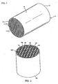
FIG. 1 illustrates a perspective view of a honeycomb green body according to embodiments of the invention. -
FIG. 2 illustrates a perspective view of a porous ceramic honeycomb filter according to further embodiments of the invention. -
FIGS. 3-6 show micrographs of the relative size and shape of various starch pore formers according to further aspects of the invention. -
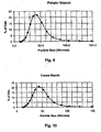
FIGS. 7-10 illustrate graphs of Particle Size vs. % of Distribution for the pore formers according to aspects of the invention. -
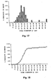
FIGS. 11-19 illustrate graphs of pore size distributions for several exemplary porous ceramic honeycomb filters according to embodiments of the invention. -
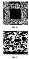
FIGS. 20-23 illustrate various micrographs of the internal pore structure of the porous wall of the filters according to embodiments of the invention. - The present invention, according to a first aspect, relates to a porous ceramic honeycomb filter article which exhibits a very small amount of small pores. More preferably, the porous ceramic honeycomb filter article includes both a very small amount of small pores and also a narrow pore size distribution. In a preferred implementation, the invention relates to a porous ceramic honeycomb filter, most useful as a diesel particulate filter. Particulate filters are useful, as described above, for filtering particulate soot from exhaust streams, for example.
- According to this first aspect, the inventors herein have recognized and discovered that controlling the size of the pores below d1 is an important factor in terms of being able to minimize the wash-coated pressure drop. In particular, controlling the size of the pores below d1 was discovered to have a dominant contribution to reducing the percentage of wash-coated pressure drop increase (i.e., the delta in back pressure between an uncoated and wash coated filter, referred to herein as "ΔPc %.") The increase attributable to d1 is much more dominant than that due to d3, d6 or d10, for example. Therefore, according to this aspect of the invention, the porous ceramic honeycomb filter preferably has walls made up of an oxide-based material having a pore size distribution exhibiting d1 ≥ 7.0 microns. d1 as used herein is defined as the pore diameter where 1% of the volume of the pore distribution of total volume of pores have a smaller pore diameter (as measured by mercury porosimetry). Thus, according to this aspect, 1% of the volume of pores have a pore diameter of less than or equal to 7.0 µm. This has the direct advantage of minimizing ΔPc % in that the only a small amount of small pores exist in the uncoated honeycomb filter's walls. Small pores have a propensity to be clogged by the wash coating which is applied to the filter as part of its normal processing to add a catalyst to the filter, such as a diesel oxidation catalyst. Thus, substantially reducing the relative amount of small pores in the walls of the filter structure, i.e., those preferably below 7.0 µm, dramatically reduces wash-coated backpressure increase.
- It should also be recognized that this aspect of the invention has the most applicability to oxide-based ceramic materials, such as materials selected from the group of cordierite and aluminum titanate. Examples of these materials are shown in Tables 2-5 below. Other cordierite-containing embodiments of the invention, as best described in Tables 2 and 3 below, achieve d1 of greater than or equal to 8.0 µm, or even greater than or equal to 9.0 µm, for example. Thus, such materials have even less propensity to have clogged pores upon wash coating and, therefore, lower wash-coated pressure increase, ΔPc %.
- The wash-coated pressure increase, ΔPc %, is defined herein as:

- In addition to the benefits achieved by controlling the amount of small pores, it is also beneficial to control the pore size distribution of the oxide-based material used for the cell walls of the filter. Providing narrow pore distribution improves filtration efficiency by reducing the percentage of relatively large pores. It also improves the strength of the filter article. Thus, according to another aspect of the invention, the overall breadth, db, of the pore size distribution should also be controlled to be relatively narrow. Thus, according to another broad aspect of the invention, an exceedingly narrow pore size distribution is provided. The pore distribution breadth, db, is used herein to measure and characterize the overall breadth, i.e., the overall narrowness of the pore size distribution of the filter's wall material. The overall breadth, db, is given by the following relationship:

- d10 is a pore diameter wherein 10% of the pore volume has a smaller pore diameter,
- d50 is a median pore diameter wherein 50% of the pore volume has a smaller pore diameter, and
- d90 is a pore diameter wherein 90% of the pore volume has a smaller pore diameter.
- In more detail, as shown and described in Tables 2 and 3 below, certain cordierite-containing embodiments are disclosed which achieve ultra narrow breadth, db. More particularly, db ≤ 1.00 is achieved by numerous examples described herein. Some embodiments achieve even narrower breadth with db ≤ 0.90 (see Ex. 2-6, 14). Still other embodiments exhibit breadth characterized by db ≤ 0.85 (see Ex. 3-5), or even db ≤ 0.75 (see Ex. 4). An aluminum titanate example according to embodiments of the invention exhibiting db ≤ 0.80 or even db ≤ 0.75 is described in Tables 4-5.
- In another broad aspect of the invention, even the smaller sized portion of the pore size distribution (that portion of the distribution equal to and below d50) is preferably also controlled to be relatively narrow. The so-called "d-factor," df, is utilized herein to measure and characterize the narrowness of the smaller pore size portion of the pore size distribution. The d-factor, df, is given by the following equation:

- Many cordierite-containing embodiments described herein also exhibit a d-factor, df, wherein df ≤ 0.38 (see Ex. 1-7, and 9-14). Such narrow pore size distribution may lower the overall pressure drop when the material is utilized to form the walls in a particulate filter (both coated and uncoated); an example filter being shown and described with reference to
Fig. 2 . Still further embodiments of the invention exhibit df ≤ 0.35 (see Ex. 1-6, 9-14), or even df ≤ 0.30 (see Ex. 4-6, 10 and 14). Examples 4-6, 10 and 14 of Tables 2 and 3 exhibit df ≤ 0.28. One particularly narrow embodiment (Ex. 4) exhibits df ≤ 0.26. - In addition, the mean pore size of the oxide-based porous material forming the cell walls of the ceramic honeycomb filter is preferably between 13 and 33 microns; more preferably between 15-30 microns; and in many embodiments, between 15-25 microns. Moreover, the oxide-based filter material preferably also includes a total volume percent porosity, P, as measured by mercury porosimetry, characterized by P ≥ 40%; more preferably P ≤ 65%; and most preferably 40% ≤ P ≤ 65%, or even 40% ≤ P ≤ 55%. This level of porosity provides good soot filtration and provides adequate heat capacity for most exhaust filtration applications.
- According to certain exemplary embodiments of the invention, as shown in Tables 2-3, the walls of the honeycomb filter article are manufactured from an oxide-based material which contains a predominantly cordierite. More preferably yet, the phase preferably approximates a stoichiometry approximating Mg2Al4Si5O18. In other embodiments, the structure contains a predominately aluminum titanate (see example in Tables 4-5 below).
- When the oxide-based material comprises a predominantly cordierite phase, it should be understood that a limited substitution of other constituents such as Fe (iron), Co (cobalt), Ni (nickel), and Mg (manganese) for the Mg (magnesium), Ga (gallium) for the Al (aluminum), and Ge (germanium) for the Si (silicon) is acceptable. Further, the cordierite phase may contain up to three atoms of an alkali (Group IA) metal, two atoms of an alkaline earth metal (Group IIA), or one atom of a rare earth metal (scandium, yttrium, or a lanthanide metal) per 54 oxygens. These substituents would be expected to occupy the normally vacant "channel sites" in the crystal structure of the cordierite-type phase, although their limited substitution for Mg might also occur. Incorporation of these elements into the cordierite crystal structure may be coupled with other chemical substitutions, such as a change in Al/Si ratio, to preserve charge balance.
- The batch composition and properties of various examples of such cordierite-containing materials are illustrated in Tables 2 and 3 below, respectively (see Examples No. 1-14). According to preferred embodiments of the inventive porous ceramic honeycomb filter, cordierite materials are employed which exhibit narrow pore size distribution and pore sizes within a defined range. In particular, the pore size distributions for the inventive filter materials preferably includes a pore structure having d10 ≥ 10 µm; more preferably d10 ≥ 12 µm. Additionally, the pore structure is preferably such that d90 ≤ 45 µm; more preferably d90 ≤ 35 µm. The mean pore diameter, d50, for these materials is preferably at least 10 µm and less than 40 µm; more preferably between 13 µm and 33 µm. Many embodiments exhibit mean pore size of between 15 µm and 30 µm; or even between 15 µm and 25 µm. Further embodiments may exhibit a narrow pore size distribution wherein porosity attributable to pores having a pore size less than 10 µm is less than 6 %, and the porosity being attributable to pores having a pore size larger than 50 µm is less than 8%.
- The porous ceramic honeycomb filter preferably exhibits a narrow pore size distribution; several examples of the pore size distribution being shown in
Figs. 11-19 . In particular,Figs. 11-13 relate to Example No. 1 including 13% sago palm starch,Figs. 14-16 relate to Example No. 2 including 13% canna starch, andFigs. 17-19 relate to Example No. 3 including 13% single-mode potato starch.Figs. 11 ,14 and17 , for example illustrate the pore diameter distribution thereby illustrating the percentage of the pore volume within each pore diameter range. For example, the tallest bar is positioned at between >16 µm and ≤18 µm and constitutes greater than 15% of the pore volume. In particular, greater than 55% of the pore volume exhibit pore diameters of >10 µm and ≤ 20 µm.Fig. 12 illustrates the cumulative % porosity in the range and that less than about 90% of the pore volume has a pore diameter of less than 28.5 µm.Fig. 13 illustrates the pore diameter for d1, d10, d50 and d90, for example, and is drawn to scale. - As was recognized by the inventors herein, achieving both relatively lower porosity and also narrow pore size distribution is a very difficult problem. However, according to certain exemplary embodiments of the invention, the narrow pore size distribution as exemplified by exhibiting df ≤ 0.3 and, in addition, porosity is achieved, with P ≤ 55%. This combination of relatively lower porosity and narrow pore size distribution provides a filter with low back pressure, excellent heat capacity, and good filtration efficiency. These examples may also provide the combination of small amount of small pores (d1 ≤ 8.0 µm) and relatively lower porosity (P≤ 55%). When achieved, this provides both low wash-coated pressure increase and improved thermal shock characteristics for the filter.
- Additionally, the honeycomb filter of the present invention preferably exhibits, as shown in Table 3, a mean coefficient of thermal expansion (CTE) from 22°C to 800°C, as measured by dilatometry, in the inventive cordierite article of less than 10.0 x 10⁻⁷ /°C; or even less than or equal to 7.0 x 10⁻⁷ /°C, and in some embodiments, less than or equal to 5 x 10⁻⁷ /°C. In certain embodiments, CTE of less than or equal to 4.0x 10⁻⁷ /°C, or even less than or equal to 3.0 x 10⁻⁷ /°C is achieved.
- According to embodiments of the invention, the honeycomb article is configured as a porous
ceramic honeycomb filter 100 as shown inFig. 2 and includes a body of material in the form of ahoneycomb structure 101. The material includes the controlled pore structure and is formed, preferably by extrusion, into a plurality of parallel cell channels (inlet cell channels 108 and outlet cell channels 110) separated byporous cell walls 106. At least some of the cell channels include preferably porous end plugs 112. Most preferably, a portion of the cell channels at theinlet end 102 are plugged with a paste having same or similar composition to that of the filter, for example as described inU.S. Pat. No. 4,329,162 . Theplugs 112 are preferably only located at the ends of thecell channels US 4,557,773 , for example. A portion of theinlet cell channels 108 are plugged on theoutlet end 104, and a portion of theoutlet channels 110 are plugged on theinlet end 102. The respective pluggedinlet channels 108 are arranged adjacent to the pluggedoutlet channels 110 such that wall flow through thecell walls 106 is accomplished in use. Therefore, preferably each cell channel is plugged only at one end. The preferred arrangement is to have every other cell on a given face plugged as in a checkered pattern as shown inFig. 2 , although any other suitable plug arrangement may be employed. - This plugging configuration allows for more intimate contact between the exhaust stream and the porous wall of the substrate. The exhaust stream flows into the substrate through the
open inlet cells 108 at theinlet end 102, then through theporous cell walls 106, and out of the structure through the open cells at theoutlet end 104. Filters of the type herein described are known as "particulate" or "wall flow" filters since the flow paths resulting from alternate channel plugging require the exhaust being treated to flow through the porous ceramic cell walls prior to exiting the filter. Thus, such porous ceramic filters are useful for filtering particulate material from an exhaust, for example, removing/filtering soot from a diesel exhaust. - The inventive filters preferably have cellular densities from about 100 cells/in2 (15.5 cells/cm2) to about 400 cells/in2 (62 cells/cm2) and wall thicknesses (in between about 100 µm and 750 µm, more preferably between 100 µm and 500 µm.
- For each example shown in Table 3, the total pore volume listed therein is measured by mercury porosimetry and is in units of cm3/gm. The total pore volume comprised of pores of below a certain diameter is calculated from the mercury porosimetry data by computing the difference between the cumulative mercury intrusion at a particular micrometer measure, dividing by the total mercury intrusion, and multiplying the result by 100. Thus; for each example, the pore size distribution is provided. As can be readily recognized, the pore size distribution is narrow for all embodiments, and exceedingly narrow for some exemplary embodiments. This narrowness may be achieved, for example, by the selection and use of specific starches described below, or by otherwise manipulating the particle size distribution of the pore former. By utilizing these specific starches or pore formers having manipulated particle size distributions, diesel particulate filters having a low was-coated pressure drop across the length of the fitter and lower overall back pressure against the engine have been achieved than was possible with cordierite' filters in the prior art.
- The method for manufacturing a porous ceramic honeycomb article comprises mixing a batch of inorganic raw materials with a pore former and forming aids. The pore former is preferably composed of a particular class of pore former. More particularly, the preferred pore former exhibits a narrow particle size distribution. "Pore former" as used herein is defined as a fugitive particulate material which evaporates or undergoes vaporization by combustion during drying or heating of the green body to obtain a desired, usually larger porosity and/or coarser median pore diameter than would be obtained otherwise without the pore former.
- In a preferred embodiment, the pore former is included in the batch mixture for forming a porous ceramic honeycomb article and has a narrow particle size distribution given by the relationship:


- dp10 is a particle size wherein 10% of the particle volume has a smaller particle size,
- dp50 is a median particle size wherein 50% of the particle volume has a smaller particle size, and
- dp90 is a particle size wherein 90% of the particle volume has a smaller particle size. Particle size is measured by a laser diffraction technique, such as a Microtrac particle size analyzer.
- According to additional embodiments of the invention, the pore former used includes even a narrower particle size distribution characterized by dps ≤ 0.85, or even dps ≤ 0.80. Most preferably, the pore former is single-moded, and preferably a starch. The term "single-moded," as used herein, means the starch particle distribution data (the plot the differential of accumulate volume via. Logarithm of particles size), measured from the "microtrac" measurement when computer fit with a Gaussian function has a correlation function of 0.98 or above. When the starches described herein are utilized as the pore former agent, the starch preferably exhibits a median particle size, dp50, of between 15 and 60 µm; and in some exemplary embodiments, between 20 and 50 µm.
- The starch pore former preferably constitutes between 1-50 wt. %; more preferably between 5-30 wt. % of the inorganic raw materials. Preferred implementations include between 5-20 wt %.; and more preferably yet between 5-15 wt. %. According to exemplary embodiments, the starch pore former utilized in the batch mixture is selected from a group consisting of canna starch, sago palm starch, green mung bean starch, and single-mode potato starch. Each of these starches is a single-moded starch. However, any starch or pore former having a narrow particle size distribution as described above may be substituted therefor. For cordierite batches, canna and single-mode starches are most preferred. For aluminum titanate batches, sago palm and green mung bean starches are most preferred. In particular, it should be recognized that the pore size distribution of the pore former may be manipulated to achieve the desired breadth as described herein. For example, the small sized particles may be sieved, sifted or otherwise separated out and removed from the distribution. Likewise, the large particle sizes in the distribution may be sieved, sifted or otherwise separated out and removed. Preferably, both are removed to provide the particle size breadth as described herein. In any case, the pore former is burned out during firing to form pores in the filter walls.
- Canna starch exhibits a narrow pore size distribution, an example of which is shown in
Fig. 10 , and includes a mean particle size, dp50, of between about 40-55 µm, and dps ≤ 0.90. Canna (Canna edulis Ker-Gawler) is a starchy root crop that is generally grown in tropical highlands, such as the Andean range, as well as in other parts of the developing world such as Vietnam, southern China, Taiwan, and Indonesia. Canna starch has large grains (seeFig. 6 ) that settle quickly out of a suspension of grated tuber tissue. The starch is high in amylose and functionally similar to mung bean starch, the traditional raw material for transparent noodles. Canna starch is very inexpensive to produce and is an outstandingly versatile and robust crop. - Sago palm starch also exhibits a narrow pore size distribution, an example of which is shown in
Fig. 4 , and includes a mean particle size, dp50, of between about 25-35 µm, and dps ≤ 0.8. Sago palm starch is prepared from the pith of several genera of palms, Metroxylon, Borassus, and Arenga, and from cycads of the genus Cycas, native to the East Indies. Sago palm starch takes on the form of small whitish, pinkish, or brownish grains (seeFig. 4 ). - Green mung bean starch also exhibits a narrow pore size distribution, an example of which is shown in
Fig. 3 , and includes a mean particle size, dp50, of between about 15-30 µm, and dps ≤ 88. Green mung bean starch is sometimes referred to as mung bean flour or green pea flour, both of which are misnomers for the fine white starch of the green mung bean. Grown in many parts of Asia, the tiny bean with olive green skin (Phaseolus aureus, Vigna radiata) is also sometimes referred to as green pea. The starch is available in its natural (white) state or tinted pink or green, the color only showing when water is added. In China, the green mung bean is referred to as "lue dau fen." - Single-mode potato starch also exhibits a narrow pore size distribution, an example of which is shown in
Fig. 9 , and includes a mean particle size, dp50, of between about 30-60 µm, and dps ≤ 0.88. Single-mode potato starch is a product of a potato grown in Japan in the northern island of Hokkaido. Single-mode potato starch takes on the form of small whitish, pinkish, or brownish grains (seeFig. 5 ). Single-mode potato starch is available under the tradename Shirakiku, for example. - The batch used for forming the ceramic honeycomb article comprises a mixture of sources of inorganic materials, and a pore former selected from a group consisting of canna starch, sago palm starch, green mung bean starch, and single-mode potato starch, as described above. The inorganic source materials include at least two selected from a group of forming sources consisting of magnesia, alumina, silica, and titania. In the case of cordierite-forming batch mixtures, the inorganic source materials include magnesia-, alumina-, and silica-forming sources. Most preferably, the source materials are as described below.
- The batch preferably also includes forming aids that may include a plasticizer, lubricant, binder, and solvent vehicle. Methocel is the preferred binder. Water is the preferred solvent vehicle. The inorganic raw materials are blended together with organic forming aids (and the solvent vehicle) to form a homogeneous plastic batch mixture. The plastic batch mixture is then preferably formed into a honeycomb green body, optionally dried, and then fired in a furnace to form the final porous honeycomb article. The forming is preferably accomplished by an extrusion process by extruding the plastic mixture from a twin screw or ram extruder through an extrusion die, as taught in
US Pat. No. 6,080,348 , for example. The extruded honeycombgreen body 10 has a honeycomb structure as shown inFig. 1 . The honeycombgreen body article 10 includes the pore former with narrow pore size distribution as described above, i.e., with dps≤ 0.9. The preferred pore former is a starch; most preferably a single-moded starch as described above. - The raw inorganic source materials preferably include one or more talc sources, one or more alumina-forming sources, and one or more silica-forming sources. Preferably, the raw material mixture also contains kaolin clay.
- In a preferred embodiment, the cordierite-forming inorganic source materials include talc, kaolin clay, a silica source such as quartz, and multiple alumina sources. The median particle sizes of the inorganic raw materials, as described below, are measured in micrometers, and are derived from the volumetric distribution of particle sizes, as measured by a laser diffraction technique.
- The preferred talc, a magnesium silicate source, has a mean particle size greater than about 15 µm, and preferably greater than about 20 µm, but preferably has a mean particle size less than 35 micrometers. The talc source may also include a calcined talc. The talc is preferably provided in a amount of between 35 and 45 wt. % of the total inorganic'materials.
- Additionally, the mixture preferably contains a clay, an aluminum silicate source, such as kaolin clay. If present, the weight percentage of kaolin should be in the range of between 12 and 20 wt. %. Weight percents of kaolin greater than this value will result in higher pressure drops for the filter.
- The silica-forming source includes, but is not limited to, quartz, cristobalite, non-crystalline silica such as fused silica or a sol-gel silica, zeolite, and diatomaceous silica, and combinations thereof. Quartz is most preferred. The average of the median particle sizes of the silica source is preferably greater than 10 µm, and is preferably between 10 and 35 µm.
- The alumina-forming source is preferably a powder which, when heated to a sufficiently high temperature in the absence of other raw materials, yields substantially pure aluminum oxide. The alumina-forming source may be an alpha-alumina, a transition alumina such a gamma-alumina or rho-alumina, boehmite, aluminum hydroxide (aluminum trihydiate), or mixtures thereof. Most preferably, the alumina-forming source comprises a combination of α-alumina (Al2O3) and aluminum trihydrate. Preferably, the weighted average of the median particle sizes of the alumina-forming sources have a median particle size of less than 10µm; more preferably less than 5 µm.
- One additional advantage of the present invention is the elimination of the pore-forming agent graphite from the raw material mixture. Graphite, when included in the green body, may be detrimental to the drying process, in that arcing may occur during drying. Additionally, graphite may produce large exothermic reactions during firing that may require longer firing cycle times or which may contribute to cracking of honeycomb articles. Use of the starch pore formers in accordance with embodiments of the present invention eliminates the need for graphite. Additionally, sufficient levels of porosity (greater than 40%) can be readily achieved with a lower weight percentage of pore former. This also has the propensity to reduce cracking during firing. Moreover, relatively high levels of porosity may be achieved with much less pore former. Alternatively, shorter firing cycles may be achieved. To more fully illustrate the invention, the following nonlimiting examples are presented. All parts, portions and percentages are on a weight basis unless otherwise stated.
- As shown in
Fig. 1 , inventive examples of cordieritegreen bodies 10 were prepared by weighing out the dry ingredients including various examples of the inventive pore formers listed in Table 2 and forming aids such as a cellulosic material, for example methyl cellulose, and sodium stearate. The dry ingredients are then mixed with a solvent vehicle, such as with water, and kneaded in a preferably stainless steel muller to form an extrudable plastic mass. The plastic mass is then formed, preferably extruded, into a green body, as described inUS 5,205,991 , for example. Upon being extruded, the cellular honeycomb green bodies are cut to a log length. - The extruded
green body 10 includes a honeycomb structure having a plurality of generallyparallel cell channels 11 formed, at least partially defined by intersecting cell walls 14 (otherwise referred to as "webs") that extend from afirst end 12 to asecond end 13. Preferably, thegreen body 10 also includes an extrudedsmooth skin 15 formed about the honeycomb structure, although this is optional and may be formed in later processing. The wall thickness of eachcell wall 14 is preferably about 0.01 to 0.03 inches (about 254 to 762 µm). All examples manufactured herein were 0.021 inch (533 µm). In a preferred implementation, the cellular honeycomb structure consists of multiplicity ofparallel cell channels 11 of generally square cross section formed into a honeycomb structure. Alternatively, other cross-sectional configurations may be used in the honeycomb structure as well, including rectangular, round, oblong, triangular, octagonal, hexagonal, or combinations thereof. The term "honeycomb structure" as used herein is defined as a connected structure of longitudinally-extending cells formed of thin cell walls, having a generally repeating pattern therein. - The green body is preferably dried using a conventional microwave or RF drier as is known to those persons of ordinary skill in the art. After drying, the parts are fired in a furnace at an average heating rate of between 1 and 100 °C/hour, more preferably between 20 and 70 °C/hour, and most preferably between 25 and 50 °C/hour, to a maximum (top) temperature of 1400 °C to 1440 °C, more preferably 1410 °C to 1440 °C, and more preferably yet between 1410 °C to 1435 °C and held at this top temperature for 1 to 30 hours, more preferably 5 to 25 hours, and most preferably 10 to 20 hours. Following firing, at least some of the cell channels are plugged, for example, as is described in
US 4,557,773 to Bonzo . Preferably, the plugs are provided in a checkerboard pattern on each respective end; wherein inlet channels are plugged at the second end and outlet channels are plugged at the first end. The plugged filter may then be re-fired. - The inventors herein discovered that by utilizing the pore formers listed herein, the pore size distribution of the present invention porous ceramic honeycomb filter may be desirably manipulated and made to be relatively narrow. In particular, by the selection and use of the pore formers and raw materials described herein, cordierite honeycomb articles, such as porous ceramic honeycomb filters, exhibiting a narrow pore size distribution may be manufactured. The narrowness of the distribution is best characterized by having a pore size breadth, db, which is relatively narrow; the narrowness being characterized by having db ≤ 1.00, wherein , db is defined by the relation:

- d10 is a pore diameter wherein 10% of the pore volume has a smaller pore diameter,
- d50 is a median pore diameter wherein 50% of the pore volume has a smaller pore diameter, and
- d90 is a pore diameter wherein 90% of the pore volume has a smaller pore diameter.
- Providing such narrow pore size distribution provides relatively lower clean pressure drop in such porous ceramic filters, as well as excellent filtration efficiency. Certain exemplary cordierite-containing embodiments exhibit db ≤ 0.90 (Ex. 2-6, 14). Other cordierite-containing embodiments exhibit exceedingly low db, such as where db ≤ 0.85 (Ex. 3-5), or even db ≤ 0.75 (Ex. 4). Additionally, such narrow pore size may be achieved white also providing low coefficient of thermal expansion (between 25-800°C) of less than 10.0 x10⁻⁷/°C. In some embodiments, coefficient of thermal expansion (25-800°C) of less than or equal to 7.0 x10⁻⁷/°C, or even 5.0 x10⁻⁷/°C or less are provided. Certain exemplary embodiments exhibit CTE of less than or equal to 4.0 x10⁻⁷/°C, or even less than or equal to 3.0 x10⁻⁷/°C. Advantageously, excellent thermal shock resistance is provided.
- Additionally, such ceramic filter articles may be made to also have few small pores in addition to a relatively narrow pore size distribution. In particular, the lack of small pores in such porous ceramic filter articles is characterized in that d1 is made small. Most preferably, such porous ceramic filters are characterized by pore size distributions which exhibit the relation:

- d1 is a pore diameter wherein 1% of a total pore volume of the pore size distribution has a smaller diameter.
- Such porous ceramic filter articles produced, when coated with a wash coat, exhibit low wash-coated pressure increase, as well as low overall back pressure and good filtration efficiency. Additionally, several embodiments of the invention exhibit the combination of both low porosity as characterized by porosity, P, wherein P ≤ 55%, small amounts of small pores are characterized by d1 ≥ 7.0 µm, and narrow pore size distribution as characterized by having db ≤ 1.00. Such filters have excellent heat capacity, low back overall clean pressure drop and low wash-coated pressure increase and good filtration efficiency.
- More particularly, the inventors herein discovered according to further embodiments of the invention that the use of certain amounts of the specific starches described herein (e.g., canna, sago, green mung bean, and single-mode potato) may be used to produce the above-described relatively narrow pore size distributions in porous ceramic cordierite filters. These starches exhibit very narrow particle distributions (as characterized by low Dfp and/or low Dps, see Table 1 below) and, thus, contribute to the relative narrowness of the cordierite ceramic material's pore size distribution.
- The narrowness of the particle size distribution for these starches is described and illustrated in Table 1 and in
Figs. 3-6. Figs. 3-6 provide information about the particle size distributions of the preferred starch materials according to embodiments of the present invention. In particular, the raw material particle sizes given below are measured by a laser diffraction technique. In particular, they are measured by a Microtrac FRA9200 Series particle size analyzer. -
TABLE 1 - Pore Former Examples Type of Starch dp10 (µm) dp50 (µm) dp50 (µm) Dfp = (d50-d10)/d50 Dps = (d90-d10)/d50 Single-mode Potato Starch 30.6 44.7 68.2 0.32 0.84 Canna Starch 31.3 47.7 73.3 0.34 0.88 Sago Palm Starch 23.5 32.6 47.8 0.28 0.74 Green Mung Bean Starch 15.8 23.6 36.9 0.33 0.84 


-
TABLE 4: Example Aluminum Titanate Composition Example No. 15 Starch Type Sago Starch Wt. % (%) 16 Inorganic Raw Materials Titania (Ti-Pure) 29.95 Al2O3 (Alcoa-A10 - 325) 46.57 Al(OH)3 AC 714 3.71 Silica 10.19 SrCO3 8.00 CaCO3 1.38 La2O3 0.20 Organic Materials Methylcellulose Binder 4.5 Emulsia "T" 9.0 -
TABLE 5 - Aluminum Titanate Example - Properties Example No. 15 Starch Type Sago Starch Wt. % (%) 16 Soak Temp (°C) 1450 Soak Time (hours) 15 Fired Properties CTE (10-7/°C) 22-800°C 5.8 Predominant Phase Aluminum Titanate Cell Density (cells/in2) Wall 300 Thickness (inches) 0.013 MOR (psi) / type 238 Porosity(%) 51 d1 (µm) 7.3 d10 (µm) . 12.9 d50 (µm) 16.5 d90 (µm) 252 dr = (d50-d10)/d50 0.219 db = (d50-d10)/d50 0.748 Distribution Data Total Intrusion Volume (cm3/g) 0.2802 Intrusion Volume at indicated pore diameter (cm3/g) 1 µm 0.2799 2 µm 0.2799 4 µm 0.2799 10 µm 0.2684 20 µm 0.0504 30 µm 0.0241 40 µm 0.0174 50 µm 0.0159 60 µm 0.0123 70 µm 0.0102 80 µm 0.0091 90 µm 0.0080 100 µm 0.0071 - Tables 4 and 5 above illustrate an example of the present invention wherein the oxide-based material forming the walls of the filter is an aluminum titanate material. As can be seen, d1 ≥ 7.0 µm for this example. Further, a narrow pore size distribution was achieved by utilizing sago starch as the pore former. The porosity may be controlled by controlling its amount between 1 and 50 wt. %; more preferably between 5 and 30 wt. %; more preferably yet between 10 and 20%. Additionally, the example filter article containing aluminum titanate includes a narrow small-sized portion of the distribution characterized by df ≤ 0.25; more preferably df ≤ 0.23; or even df ≤ 0.22. Furthermore, the filter article includes narrow overall pore size distribution, as exemplified by db ≤ 0.9; more preferably db ≤ 0.8; or even db ≤ 0.75. Additionally, the filter article containing aluminum titanate includes controlled porosity, P, wherein P % ≤ 55%. Preferably also, the article includes d90 < 30 µm. Additionally, d50 is preferably between 10 and 20 µm for filters containing aluminum titanate material. CTE for the article containing aluminum titanate is less than
15x 10-7/°C; preferably less than10x 10-7/°C, or even less than 6 x 10⁻⁷/°C, all as measured between room temperature and 1000°C.
Claims (12)
- A porous ceramic honeycomb filter, comprising:an oxide-based ceramic material having many pores with a pore size distribution including d1 ≥ 7.0 microns, wherein d1 is a pore diameter wherein 1.0% of a total pore volume of the pore size distribution has a smaller diameter.
- The porous ceramic honeycomb filter of claim 1 wherein the oxide-based ceramic material is selected from a group consisting of cordierite and aluminum titanate.
- The porous ceramic honeycomb filter of claim 2 wherein d1 ≥ 8.0 microns.
- The porous ceramic honeycomb filter of claim 1 further comprising:d10 ≥ 10 µm,d50 of between 15 and 30 µm, andd90 ≤ 45 µmwherein d10 is a pore size wherein 10% of the pore volume has a smaller pore diameter, d50 is a median pore size wherein 50% of the pore volume has a smaller pore diameter, and d90 is a pore size wherein 90% of the pore volume has a smaller pore diameter.
- The porous ceramic honeycomb filter of claim 1 wherein the material comprises cordierite and dr ≤ 0.38, whereindf = (d50-d10) /d50d10 is a pore size where 10% of the pore volume has a smaller pore diameter, andd50 is a median pore size where 50% of the pore volume has a smaller pore diameter.
- The porous ceramic honeycomb filter of claim 5 further comprising dr ≤ 0.25.
- The porous ceramic honeycomb filter of claim 1 wherein the material comprises cordierite and db ≤ 1.00, wherein db = (d90-d10)/d50
and wherein d10 is a pore size wherein 10% of the pore volume has a smaller pore diameter, d50 is a median pore size wherein 50% of the pore volume has a smaller pore diameter, and d90 is a pore size wherein 90% of the pore volume has a smaller pore diameter. - The porous ceramic honeycomb filter of claim 7 further comprising db ≤ 0.75.
- The porous ceramic honeycomb filter of claim 1 further comprising a coefficient of thermal expansion (22-800°C) of less than or equal to 5.0 x 10⁻⁷ /°C.
- The porous ceramic honeycomb filter of claim 1, further comprising:d1 ≥ 8.0 µm, andporosity (P) wherein P < 55%.
- The porous ceramic honeycomb filter of claim 1 wherein the pores are formed, at least in part, by burning out a pore former, wherein said pore former is a single-mode starch.
- The porous ceramic honeycomb filter of claim 11 wherein the pore former is selected from a group consisting of canna starch, sago palm starch, green mung bean starch, and a single-mode potato starch.
Applications Claiming Priority (2)
| Application Number | Priority Date | Filing Date | Title |
|---|---|---|---|
| US74135505P | 2005-11-30 | 2005-11-30 | |
| PCT/US2006/043619 WO2007064454A2 (en) | 2005-11-30 | 2006-11-09 | Controlled pore size distribution porous ceramic honeycomb filter, honeycomb green body, batch mixture and manufacturing method therefor |
Publications (2)
| Publication Number | Publication Date |
|---|---|
| EP1966108A2 EP1966108A2 (en) | 2008-09-10 |
| EP1966108B1 true EP1966108B1 (en) | 2012-01-11 |
Family
ID=37969786
Family Applications (1)
| Application Number | Title | Priority Date | Filing Date |
|---|---|---|---|
| EP06844303A Active EP1966108B1 (en) | 2005-11-30 | 2006-11-09 | Controlled pore size distribution porous ceramic honeycomb filter |
Country Status (6)
| Country | Link |
|---|---|
| US (1) | US7744670B2 (en) |
| EP (1) | EP1966108B1 (en) |
| JP (1) | JP4824769B2 (en) |
| CN (1) | CN101316804B (en) |
| AT (1) | ATE540907T1 (en) |
| WO (1) | WO2007064454A2 (en) |
Families Citing this family (67)
| Publication number | Priority date | Publication date | Assignee | Title |
|---|---|---|---|---|
| US20050050870A1 (en) * | 2003-03-03 | 2005-03-10 | Cheng Shi-Wai S. | Method and apparatus for filtering exhaust particulates |
| US10501375B2 (en) | 2006-06-30 | 2019-12-10 | Corning Incorporated | Cordierite aluminum magnesium titanate compositions and ceramic articles comprising same |
| US8956436B2 (en) | 2006-06-30 | 2015-02-17 | Corning Incorporated | Cordierite aluminum magnesium titanate compositions and ceramic articles comprising same |
| US8298311B2 (en) * | 2006-11-15 | 2012-10-30 | Corning Incorporated | Filters with controlled submicron porosity |
| US8388721B2 (en) * | 2006-11-30 | 2013-03-05 | Hitachi Metals, Ltd. | Ceramic honeycomb filter and its production method |
| US20080138569A1 (en) * | 2006-12-11 | 2008-06-12 | Adam Kent Collier | Alpha-alumina inorganic membrane support and method of making the same |
| MY151327A (en) * | 2007-01-31 | 2014-05-15 | Basf Catalysts Llc | Gas catalysts comprising porous wall honeycombs |
| EP2125667A1 (en) * | 2007-03-20 | 2009-12-02 | Corning Incorporated | Low shrinkage plugging mixture for ceramic filter, plugged honeycomb filter and method of manufacturing same |
| DE102007024871A1 (en) * | 2007-05-29 | 2008-12-04 | Robert Bosch Gmbh | Ceramic filter element with low depth filtration |
| US8709577B2 (en) * | 2007-06-28 | 2014-04-29 | Corning Incorporated | High porosity ceramic honeycomb article containing rare earth oxide and method of manufacturing same |
| US8814974B2 (en) * | 2007-08-24 | 2014-08-26 | Corning Incorporated | Thin-walled porous ceramic wall-flow filter |
| EP2188228B1 (en) | 2007-08-31 | 2018-09-26 | Corning Incorporated | Cordierite honeycomb article and method of manufacture |
| US8187525B2 (en) * | 2007-08-31 | 2012-05-29 | Corning Incorporated | Method of firing green bodies into porous ceramic articles |
| CN101959571B (en) * | 2007-10-12 | 2013-06-12 | 日立金属株式会社 | Cordierite ceramic honeycomb filter and process for producing the same |
| US8114354B2 (en) * | 2007-12-18 | 2012-02-14 | Basf Corporation | Catalyzed soot filter manufacture and systems |
| US8038954B2 (en) * | 2008-02-14 | 2011-10-18 | Basf Corporation | CSF with low platinum/palladium ratios |
| CN102015579A (en) | 2008-02-29 | 2011-04-13 | 康宁股份有限公司 | Honeycomb manufacturing method using ground nut shells and honeycomb body produced thereby |
| WO2009110978A2 (en) * | 2008-02-29 | 2009-09-11 | Corning Incorporated | Method for porous ceramic honeycomb shrinkage reduction |
| WO2009119748A1 (en) * | 2008-03-26 | 2009-10-01 | 京セラ株式会社 | Porous ceramic member, method for producing the same, and filter |
| WO2009122532A1 (en) * | 2008-03-31 | 2009-10-08 | イビデン株式会社 | Honeycomb structure |
| JPWO2009122534A1 (en) | 2008-03-31 | 2011-07-28 | イビデン株式会社 | Honeycomb structure |
| DE102008001125A1 (en) * | 2008-04-11 | 2009-10-15 | Evonik Degussa Gmbh | Copolyamide powder as a pore-forming agent in regenerable ceramic particle filters |
| US20090298670A1 (en) * | 2008-05-27 | 2009-12-03 | Martin Joseph Murtagh | Method for removing graphite from cordierite bodies |
| US8894917B2 (en) * | 2008-05-30 | 2014-11-25 | Corning Incorporated | High porosity cordierite honeycomb articles |
| US9314727B2 (en) | 2008-11-26 | 2016-04-19 | Corning Incorporated | Cordierite forming batch compositions and cordierite bodies manufactured therefrom |
| US8530029B2 (en) * | 2008-11-26 | 2013-09-10 | Corning Incorporated | Low thermal mass cordierite bodies and methods for making same |
| CN102272073A (en) * | 2009-01-07 | 2011-12-07 | 住友化学株式会社 | Molded porous ceramic article, and method for manufacturing same |
| US8231701B2 (en) * | 2009-01-21 | 2012-07-31 | Corning Incorporated | Particulate filters and methods for regenerating particulate filters |
| US8138108B2 (en) * | 2009-02-27 | 2012-03-20 | Corning Incorporated | Aluminum titanate-containing ceramic-forming batch materials and methods using the same |
| KR101770654B1 (en) * | 2009-09-04 | 2017-08-23 | 히타치 긴조쿠 가부시키가이샤 | Ceramic honeycomb structure and its production method |
| US20110124486A1 (en) * | 2009-11-24 | 2011-05-26 | Bonham Christine Gallaher | Aluminum Titanate-Containing Ceramic-Forming Batch Materials And Methods Using The Same |
| US8148297B2 (en) * | 2009-11-30 | 2012-04-03 | Corning Incorporated | Reticular cordierite composition, article and manufacture thereof |
| JP5502000B2 (en) * | 2010-03-19 | 2014-05-28 | 住友化学株式会社 | Honeycomb structure and particulate filter |
| EP2554237B1 (en) * | 2010-04-01 | 2016-11-02 | Hitachi Metals, Ltd. | Ceramic honeycomb filter and method for producing same |
| US8450227B2 (en) * | 2011-02-28 | 2013-05-28 | Corning Incorporated | Ceramic-body-forming batch materials comprising silica, methods using the same and ceramic bodies made therefrom |
| JP2012206079A (en) * | 2011-03-30 | 2012-10-25 | Ngk Insulators Ltd | Honeycomb filter |
| JP5937381B2 (en) * | 2012-03-06 | 2016-06-22 | 日本碍子株式会社 | Honeycomb structure |
| EP2832417A4 (en) * | 2012-03-30 | 2016-05-25 | Ngk Insulators Ltd | Porous body, honeycomb filter and manufacturing method for porous body |
| US9126871B2 (en) | 2012-05-31 | 2015-09-08 | Corning Incorporated | Carbonates as relic pore formers in aluminum titanate |
| EP2885257A1 (en) | 2012-08-16 | 2015-06-24 | Dow Global Technologies LLC | Method of preparing high porosity ceramic material |
| US10526249B2 (en) * | 2012-11-30 | 2020-01-07 | Corning Incorporated | Cordierite aluminum magnesium titanate compositions and ceramic articles comprising same |
| CN105143145B (en) * | 2013-04-03 | 2017-06-23 | 迪耐斯公司 | cellular component |
| US9908260B2 (en) | 2013-05-20 | 2018-03-06 | Corning Incorporated | Porous ceramic article and method of manufacturing the same |
| US9623360B2 (en) | 2013-05-20 | 2017-04-18 | Corning Incorporated | Porous ceramic article and method of manufacturing the same |
| US9376347B2 (en) | 2013-05-20 | 2016-06-28 | Corning Incorporated | Porous ceramic article and method of manufacturing the same |
| JP6239303B2 (en) | 2013-07-31 | 2017-11-29 | イビデン株式会社 | Honeycomb filter |
| JP6239304B2 (en) * | 2013-07-31 | 2017-11-29 | イビデン株式会社 | Honeycomb filter |
| US10472291B2 (en) | 2013-10-15 | 2019-11-12 | Corning Incorporated | Crosslinked starches for pore forming in ceramics |
| DE102013019582A1 (en) * | 2013-11-21 | 2015-05-21 | Karlsruher Institut für Technologie | Process for producing porous sintered bodies |
| CN108367224B (en) | 2015-12-09 | 2022-04-29 | 康宁股份有限公司 | Porous ceramic materials, filters and articles |
| JP6715647B2 (en) * | 2016-03-31 | 2020-07-01 | 日本碍子株式会社 | Microstructure analysis method, its program, and microstructure analysis device |
| WO2017210251A1 (en) | 2016-05-31 | 2017-12-07 | Corning Incorporated | Porous article and method of manufacturing the same |
| JP2019522615A (en) * | 2016-06-13 | 2019-08-15 | コーニング インコーポレイテッド | Aluminum titanate composition, aluminum titanate article, and method for producing the same |
| JP6845645B2 (en) * | 2016-09-26 | 2021-03-24 | タテホ化学工業株式会社 | Magnesium oxide-containing spinel powder and its manufacturing method |
| JP6802096B2 (en) * | 2017-03-14 | 2020-12-16 | 日本碍子株式会社 | Sealed honeycomb structure |
| JP7396989B2 (en) | 2017-10-31 | 2023-12-12 | コーニング インコーポレイテッド | Batch composition comprising pre-reacted spherical inorganic particles and spherical pore forming agent and method for producing honeycomb bodies therefrom |
| JP6982530B2 (en) * | 2018-03-23 | 2021-12-17 | 日本碍子株式会社 | Honeycomb structure |
| CN112969673A (en) | 2018-08-31 | 2021-06-15 | 康宁股份有限公司 | Cordierite-indialite-pseudobrookite structural ceramic bodies, batch composition mixtures, and methods of making ceramic bodies |
| US11691137B2 (en) * | 2019-03-28 | 2023-07-04 | Ngk Insulators, Ltd. | Ceramic porous body and method for producing the same, and dust collecting filter |
| US11505503B2 (en) | 2019-04-18 | 2022-11-22 | Corning Incorporated | Ceramic honeycomb bodies and manufacture |
| JP7127606B2 (en) | 2019-04-24 | 2022-08-30 | 株式会社デンソー | Exhaust gas purification filter |
| JP6947200B2 (en) | 2019-05-15 | 2021-10-13 | 株式会社デンソー | Exhaust gas purification filter |
| JP7202324B2 (en) * | 2020-03-02 | 2023-01-11 | 日本碍子株式会社 | Honeycomb filter manufacturing method |
| JP7198789B2 (en) * | 2020-03-02 | 2023-01-04 | 日本碍子株式会社 | Honeycomb filter manufacturing method |
| CN114311232B (en) * | 2020-09-29 | 2023-02-10 | 三达膜科技(厦门)有限公司 | Preparation method of large-diameter combined honeycomb ceramic filter membrane |
| JP7178432B2 (en) * | 2021-01-18 | 2022-11-25 | 本田技研工業株式会社 | exhaust purification filter |
| CN114634354B (en) * | 2022-03-15 | 2023-04-25 | 深圳市基克纳科技有限公司 | Method for improving comprehensive performance stability of porous ceramic atomizing core |
Family Cites Families (33)
| Publication number | Priority date | Publication date | Assignee | Title |
|---|---|---|---|---|
| US2185859A (en) * | 1938-11-14 | 1940-01-02 | Massey Peter Jay | Method of coating paper |
| US4329162A (en) | 1980-07-03 | 1982-05-11 | Corning Glass Works | Diesel particulate trap |
| US4557773A (en) | 1981-07-15 | 1985-12-10 | Corning Glass Works | Method for selectively manifolding honeycomb structures |
| US4390355A (en) | 1982-02-02 | 1983-06-28 | General Motors Corporation | Wall-flow monolith filter |
| US4416676A (en) | 1982-02-22 | 1983-11-22 | Corning Glass Works | Honeycomb filter and method of making it |
| US4414337A (en) * | 1982-05-19 | 1983-11-08 | Westinghouse Electric Corp. | Shaped ceramics |
| US4509966A (en) | 1983-05-18 | 1985-04-09 | General Motors Corporation | Wall-flow monolith filter with porous plugs |
| JPH07183Y2 (en) | 1987-03-16 | 1995-01-11 | 日本碍子株式会社 | Ceramic honeycomb structure |
| JP2578176B2 (en) | 1988-08-12 | 1997-02-05 | 日本碍子株式会社 | Porous ceramic honeycomb filter and method for producing the same |
| JPH0738930B2 (en) | 1990-03-30 | 1995-05-01 | 日本碍子株式会社 | Manufacturing method of porous ceramic filter |
| US5258150A (en) | 1991-12-06 | 1993-11-02 | Corning Incorporated | Fabrication of low thermal expansion, high porosity cordierite body |
| JP2726616B2 (en) | 1993-12-15 | 1998-03-11 | 日本碍子株式会社 | Porous ceramic honeycomb filter |
| DE4419243A1 (en) * | 1994-06-01 | 1995-12-07 | Kempten Elektroschmelz Gmbh | Porous SiC sliding material with trimodal pore composition |
| WO1999020445A1 (en) | 1997-10-17 | 1999-04-29 | Corning Incorporated | Modified slot extrusion die |
| JP2002530175A (en) * | 1998-11-20 | 2002-09-17 | コーニンクレッカ フィリップス エレクトロニクス エヌ ヴィ | Catalyst-carrying filter |
| EP1255712A4 (en) | 1999-10-05 | 2004-12-08 | Corning Inc | Refractory nzp-type structures and method of making and using same |
| JP2001269522A (en) | 2000-03-27 | 2001-10-02 | Ngk Insulators Ltd | Filter made of porous ceramics sintered body |
| MXPA02011870A (en) | 2000-06-01 | 2003-04-10 | Corning Inc | Cordierite body. |
| JP4094830B2 (en) * | 2000-11-24 | 2008-06-04 | 日本碍子株式会社 | Porous honeycomb filter and manufacturing method thereof |
| JP3925225B2 (en) | 2001-03-28 | 2007-06-06 | 株式会社デンソー | Exhaust gas purification filter and manufacturing method thereof |
| JP4007058B2 (en) | 2001-08-06 | 2007-11-14 | 株式会社デンソー | Exhaust gas purification filter |
| US6897175B2 (en) * | 2001-10-09 | 2005-05-24 | General Electric | Catalyst and method for the alkylation of hydroxyaromatic compounds |
| JP2003277162A (en) | 2002-01-21 | 2003-10-02 | Ngk Insulators Ltd | Porous honeycomb structural body, application thereof and manufacturing method therefor |
| AU2003279633A1 (en) * | 2002-06-26 | 2004-01-19 | Corning Incorporated | Magnesium aluminum silicate structures for dpf applications |
| US6864198B2 (en) * | 2003-01-30 | 2005-03-08 | Corning Incorporated | Cordierite ceramic body and method |
| US20040152593A1 (en) | 2003-01-30 | 2004-08-05 | Cutler Willard A. | Catalyst support |
| US7179316B2 (en) * | 2003-06-25 | 2007-02-20 | Corning Incorporated | Cordierite filters with reduced pressure drop |
| JP4420655B2 (en) * | 2003-11-25 | 2010-02-24 | 株式会社キャタラー | Particulate filter catalyst and method for producing the same |
| US20060021308A1 (en) * | 2004-07-29 | 2006-02-02 | Merkel Gregory A | Mullite-aluminum titanate body and method for making same |
| KR100865101B1 (en) | 2004-09-14 | 2008-10-24 | 니뽄 가이시 가부시키가이샤 | Porous honeycomb filter |
| PL1707251T3 (en) * | 2004-12-28 | 2013-03-29 | Ibiden Co Ltd | Filter and filter aggregate |
| EP1890983B1 (en) * | 2005-05-31 | 2012-12-12 | Corning Incorporated | Aluminum titanate ceramic forming batch mixtures and green bodies including pore former combinations and methods of manufacturing and firing same |
| US7520911B2 (en) * | 2005-11-30 | 2009-04-21 | Corning Incorporated | Porous cordierite ceramic honeycomb article with improved strength and method of manufacturing same |
-
2006
- 2006-11-09 AT AT06844303T patent/ATE540907T1/en active
- 2006-11-09 WO PCT/US2006/043619 patent/WO2007064454A2/en active Application Filing
- 2006-11-09 EP EP06844303A patent/EP1966108B1/en active Active
- 2006-11-09 JP JP2008543301A patent/JP4824769B2/en active Active
- 2006-11-09 CN CN200680044636XA patent/CN101316804B/en active Active
- 2006-11-30 US US11/606,797 patent/US7744670B2/en active Active
Also Published As
| Publication number | Publication date |
|---|---|
| US7744670B2 (en) | 2010-06-29 |
| US20070119135A1 (en) | 2007-05-31 |
| CN101316804B (en) | 2012-09-19 |
| WO2007064454A2 (en) | 2007-06-07 |
| JP2009517211A (en) | 2009-04-30 |
| ATE540907T1 (en) | 2012-01-15 |
| JP4824769B2 (en) | 2011-11-30 |
| WO2007064454A3 (en) | 2007-07-19 |
| CN101316804A (en) | 2008-12-03 |
| EP1966108A2 (en) | 2008-09-10 |
Similar Documents
| Publication | Publication Date | Title |
|---|---|---|
| EP1966108B1 (en) | Controlled pore size distribution porous ceramic honeycomb filter | |
| US7981188B2 (en) | Controlled pore size distribution porous ceramic honeycomb filter, honeycomb green body, batch mixture and manufacturing method therefor | |
| EP2188228B1 (en) | Cordierite honeycomb article and method of manufacture | |
| EP1968913B1 (en) | Narrow pore size distribution cordierite ceramic honeycomb articles and methods for manufacturing same | |
| EP2254678B1 (en) | Honeycomb manufacturing method using ground nut shells | |
| JP5178715B2 (en) | Cordierite aluminum magnesium titanate composition and ceramic product containing the composition | |
| EP1628929B1 (en) | Cordierite ceramic body and method | |
| US20070261378A1 (en) | High porosity cordierite composition | |
| EP1515787A1 (en) | Magnesium aluminum silicate structures for dpf applications | |
| US20240116819A1 (en) | Cordierite-indialite-pseudobrookite structured ceramic bodies, batch composition mixtures, and methods of manufacturing ceramic bodies therefrom | |
| JP7232908B2 (en) | Cordierite-containing ceramic bodies, batch composition mixtures, and methods of making cordierite-containing ceramic bodies | |
| JP2019515859A (en) | High porosity ceramic honeycomb structure and method of manufacture |
Legal Events
| Date | Code | Title | Description |
|---|---|---|---|
| PUAI | Public reference made under article 153(3) epc to a published international application that has entered the european phase |
Free format text: ORIGINAL CODE: 0009012 |
|
| 17P | Request for examination filed |
Effective date: 20080618 |
|
| AK | Designated contracting states |
Kind code of ref document: A2 Designated state(s): AT BE BG CH CY CZ DE DK EE ES FI FR GB GR HU IE IS IT LI LT LU LV MC NL PL PT RO SE SI SK TR |
|
| RIN1 | Information on inventor provided before grant (corrected) |
Inventor name: WANG, JIANGUO Inventor name: SKOLNY, JENNIFER L Inventor name: XIE, YUMING Inventor name: MIAO, WEIGUO Inventor name: SHUSTACK, PAUL J |
|
| 17Q | First examination report despatched |
Effective date: 20100317 |
|
| RTI1 | Title (correction) |
Free format text: CONTROLLED PORE SIZE DISTRIBUTION POROUS CERAMIC HONEYCOMB FILTER |
|
| GRAP | Despatch of communication of intention to grant a patent |
Free format text: ORIGINAL CODE: EPIDOSNIGR1 |
|
| GRAS | Grant fee paid |
Free format text: ORIGINAL CODE: EPIDOSNIGR3 |
|
| GRAA | (expected) grant |
Free format text: ORIGINAL CODE: 0009210 |
|
| AK | Designated contracting states |
Kind code of ref document: B1 Designated state(s): AT BE BG CH CY CZ DE DK EE ES FI FR GB GR HU IE IS IT LI LT LU LV MC NL PL PT RO SE SI SK TR |
|
| DAX | Request for extension of the european patent (deleted) | ||
| REG | Reference to a national code |
Ref country code: GB Ref legal event code: FG4D |
|
| REG | Reference to a national code |
Ref country code: CH Ref legal event code: EP |
|
| REG | Reference to a national code |
Ref country code: AT Ref legal event code: REF Ref document number: 540907 Country of ref document: AT Kind code of ref document: T Effective date: 20120115 |
|
| REG | Reference to a national code |
Ref country code: IE Ref legal event code: FG4D |
|
| REG | Reference to a national code |
Ref country code: DE Ref legal event code: R096 Ref document number: 602006027105 Country of ref document: DE Effective date: 20120308 |
|
| REG | Reference to a national code |
Ref country code: NL Ref legal event code: VDEP Effective date: 20120111 |
|
| PG25 | Lapsed in a contracting state [announced via postgrant information from national office to epo] |
Ref country code: SI Free format text: LAPSE BECAUSE OF FAILURE TO SUBMIT A TRANSLATION OF THE DESCRIPTION OR TO PAY THE FEE WITHIN THE PRESCRIBED TIME-LIMIT Effective date: 20120111 |
|
| LTIE | Lt: invalidation of european patent or patent extension |
Effective date: 20120111 |
|
| PG25 | Lapsed in a contracting state [announced via postgrant information from national office to epo] |
Ref country code: LT Free format text: LAPSE BECAUSE OF FAILURE TO SUBMIT A TRANSLATION OF THE DESCRIPTION OR TO PAY THE FEE WITHIN THE PRESCRIBED TIME-LIMIT Effective date: 20120111 Ref country code: BG Free format text: LAPSE BECAUSE OF FAILURE TO SUBMIT A TRANSLATION OF THE DESCRIPTION OR TO PAY THE FEE WITHIN THE PRESCRIBED TIME-LIMIT Effective date: 20120411 Ref country code: IS Free format text: LAPSE BECAUSE OF FAILURE TO SUBMIT A TRANSLATION OF THE DESCRIPTION OR TO PAY THE FEE WITHIN THE PRESCRIBED TIME-LIMIT Effective date: 20120511 Ref country code: NL Free format text: LAPSE BECAUSE OF FAILURE TO SUBMIT A TRANSLATION OF THE DESCRIPTION OR TO PAY THE FEE WITHIN THE PRESCRIBED TIME-LIMIT Effective date: 20120111 Ref country code: BE Free format text: LAPSE BECAUSE OF FAILURE TO SUBMIT A TRANSLATION OF THE DESCRIPTION OR TO PAY THE FEE WITHIN THE PRESCRIBED TIME-LIMIT Effective date: 20120111 |
|
| PG25 | Lapsed in a contracting state [announced via postgrant information from national office to epo] |
Ref country code: PT Free format text: LAPSE BECAUSE OF FAILURE TO SUBMIT A TRANSLATION OF THE DESCRIPTION OR TO PAY THE FEE WITHIN THE PRESCRIBED TIME-LIMIT Effective date: 20120511 Ref country code: PL Free format text: LAPSE BECAUSE OF FAILURE TO SUBMIT A TRANSLATION OF THE DESCRIPTION OR TO PAY THE FEE WITHIN THE PRESCRIBED TIME-LIMIT Effective date: 20120111 Ref country code: LV Free format text: LAPSE BECAUSE OF FAILURE TO SUBMIT A TRANSLATION OF THE DESCRIPTION OR TO PAY THE FEE WITHIN THE PRESCRIBED TIME-LIMIT Effective date: 20120111 Ref country code: GR Free format text: LAPSE BECAUSE OF FAILURE TO SUBMIT A TRANSLATION OF THE DESCRIPTION OR TO PAY THE FEE WITHIN THE PRESCRIBED TIME-LIMIT Effective date: 20120412 Ref country code: FI Free format text: LAPSE BECAUSE OF FAILURE TO SUBMIT A TRANSLATION OF THE DESCRIPTION OR TO PAY THE FEE WITHIN THE PRESCRIBED TIME-LIMIT Effective date: 20120111 |
|
| REG | Reference to a national code |
Ref country code: AT Ref legal event code: MK05 Ref document number: 540907 Country of ref document: AT Kind code of ref document: T Effective date: 20120111 |
|
| PG25 | Lapsed in a contracting state [announced via postgrant information from national office to epo] |
Ref country code: CY Free format text: LAPSE BECAUSE OF FAILURE TO SUBMIT A TRANSLATION OF THE DESCRIPTION OR TO PAY THE FEE WITHIN THE PRESCRIBED TIME-LIMIT Effective date: 20120111 |
|
| PG25 | Lapsed in a contracting state [announced via postgrant information from national office to epo] |
Ref country code: EE Free format text: LAPSE BECAUSE OF FAILURE TO SUBMIT A TRANSLATION OF THE DESCRIPTION OR TO PAY THE FEE WITHIN THE PRESCRIBED TIME-LIMIT Effective date: 20120111 Ref country code: RO Free format text: LAPSE BECAUSE OF FAILURE TO SUBMIT A TRANSLATION OF THE DESCRIPTION OR TO PAY THE FEE WITHIN THE PRESCRIBED TIME-LIMIT Effective date: 20120111 Ref country code: DK Free format text: LAPSE BECAUSE OF FAILURE TO SUBMIT A TRANSLATION OF THE DESCRIPTION OR TO PAY THE FEE WITHIN THE PRESCRIBED TIME-LIMIT Effective date: 20120111 Ref country code: SE Free format text: LAPSE BECAUSE OF FAILURE TO SUBMIT A TRANSLATION OF THE DESCRIPTION OR TO PAY THE FEE WITHIN THE PRESCRIBED TIME-LIMIT Effective date: 20120111 Ref country code: CZ Free format text: LAPSE BECAUSE OF FAILURE TO SUBMIT A TRANSLATION OF THE DESCRIPTION OR TO PAY THE FEE WITHIN THE PRESCRIBED TIME-LIMIT Effective date: 20120111 |
|
| PLBE | No opposition filed within time limit |
Free format text: ORIGINAL CODE: 0009261 |
|
| STAA | Information on the status of an ep patent application or granted ep patent |
Free format text: STATUS: NO OPPOSITION FILED WITHIN TIME LIMIT |
|
| PG25 | Lapsed in a contracting state [announced via postgrant information from national office to epo] |
Ref country code: SK Free format text: LAPSE BECAUSE OF FAILURE TO SUBMIT A TRANSLATION OF THE DESCRIPTION OR TO PAY THE FEE WITHIN THE PRESCRIBED TIME-LIMIT Effective date: 20120111 |
|
| 26N | No opposition filed |
Effective date: 20121012 |
|
| PG25 | Lapsed in a contracting state [announced via postgrant information from national office to epo] |
Ref country code: AT Free format text: LAPSE BECAUSE OF FAILURE TO SUBMIT A TRANSLATION OF THE DESCRIPTION OR TO PAY THE FEE WITHIN THE PRESCRIBED TIME-LIMIT Effective date: 20120111 |
|
| REG | Reference to a national code |
Ref country code: DE Ref legal event code: R097 Ref document number: 602006027105 Country of ref document: DE Effective date: 20121012 |
|
| PG25 | Lapsed in a contracting state [announced via postgrant information from national office to epo] |
Ref country code: ES Free format text: LAPSE BECAUSE OF FAILURE TO SUBMIT A TRANSLATION OF THE DESCRIPTION OR TO PAY THE FEE WITHIN THE PRESCRIBED TIME-LIMIT Effective date: 20120422 |
|
| REG | Reference to a national code |
Ref country code: CH Ref legal event code: PL |
|
| GBPC | Gb: european patent ceased through non-payment of renewal fee |
Effective date: 20121109 |
|
| PG25 | Lapsed in a contracting state [announced via postgrant information from national office to epo] |
Ref country code: CH Free format text: LAPSE BECAUSE OF NON-PAYMENT OF DUE FEES Effective date: 20121130 Ref country code: LI Free format text: LAPSE BECAUSE OF NON-PAYMENT OF DUE FEES Effective date: 20121130 |
|
| REG | Reference to a national code |
Ref country code: IE Ref legal event code: MM4A |
|
| PG25 | Lapsed in a contracting state [announced via postgrant information from national office to epo] |
Ref country code: IE Free format text: LAPSE BECAUSE OF NON-PAYMENT OF DUE FEES Effective date: 20121109 |
|
| PG25 | Lapsed in a contracting state [announced via postgrant information from national office to epo] |
Ref country code: GB Free format text: LAPSE BECAUSE OF NON-PAYMENT OF DUE FEES Effective date: 20121109 |
|
| PG25 | Lapsed in a contracting state [announced via postgrant information from national office to epo] |
Ref country code: TR Free format text: LAPSE BECAUSE OF FAILURE TO SUBMIT A TRANSLATION OF THE DESCRIPTION OR TO PAY THE FEE WITHIN THE PRESCRIBED TIME-LIMIT Effective date: 20120111 Ref country code: MC Free format text: LAPSE BECAUSE OF NON-PAYMENT OF DUE FEES Effective date: 20121130 |
|
| PG25 | Lapsed in a contracting state [announced via postgrant information from national office to epo] |
Ref country code: LU Free format text: LAPSE BECAUSE OF NON-PAYMENT OF DUE FEES Effective date: 20121109 |
|
| PG25 | Lapsed in a contracting state [announced via postgrant information from national office to epo] |
Ref country code: HU Free format text: LAPSE BECAUSE OF FAILURE TO SUBMIT A TRANSLATION OF THE DESCRIPTION OR TO PAY THE FEE WITHIN THE PRESCRIBED TIME-LIMIT Effective date: 20061109 |
|
| REG | Reference to a national code |
Ref country code: FR Ref legal event code: PLFP Year of fee payment: 10 |
|
| REG | Reference to a national code |
Ref country code: FR Ref legal event code: PLFP Year of fee payment: 11 |
|
| REG | Reference to a national code |
Ref country code: FR Ref legal event code: PLFP Year of fee payment: 12 |
|
| REG | Reference to a national code |
Ref country code: FR Ref legal event code: PLFP Year of fee payment: 13 |
|
| PGFP | Annual fee paid to national office [announced via postgrant information from national office to epo] |
Ref country code: FR Payment date: 20191029 Year of fee payment: 14 Ref country code: IT Payment date: 20191113 Year of fee payment: 14 |
|
| PG25 | Lapsed in a contracting state [announced via postgrant information from national office to epo] |
Ref country code: IT Free format text: LAPSE BECAUSE OF NON-PAYMENT OF DUE FEES Effective date: 20201109 Ref country code: FR Free format text: LAPSE BECAUSE OF NON-PAYMENT OF DUE FEES Effective date: 20201130 |
|
| P01 | Opt-out of the competence of the unified patent court (upc) registered |
Effective date: 20230527 |
|
| PGFP | Annual fee paid to national office [announced via postgrant information from national office to epo] |
Ref country code: DE Payment date: 20231010 Year of fee payment: 18 |