EP1967784A2 - Improved line and rope system and method for movement of an object through three-dimensional space - Google Patents
Improved line and rope system and method for movement of an object through three-dimensional space Download PDFInfo
- Publication number
- EP1967784A2 EP1967784A2 EP08004178A EP08004178A EP1967784A2 EP 1967784 A2 EP1967784 A2 EP 1967784A2 EP 08004178 A EP08004178 A EP 08004178A EP 08004178 A EP08004178 A EP 08004178A EP 1967784 A2 EP1967784 A2 EP 1967784A2
- Authority
- EP
- European Patent Office
- Prior art keywords
- line
- movement
- corner
- support
- pulley
- Prior art date
- Legal status (The legal status is an assumption and is not a legal conclusion. Google has not performed a legal analysis and makes no representation as to the accuracy of the status listed.)
- Withdrawn
Links
Images


Classifications
-
- B—PERFORMING OPERATIONS; TRANSPORTING
- B66—HOISTING; LIFTING; HAULING
- B66C—CRANES; LOAD-ENGAGING ELEMENTS OR DEVICES FOR CRANES, CAPSTANS, WINCHES, OR TACKLES
- B66C13/00—Other constructional features or details
- B66C13/04—Auxiliary devices for controlling movements of suspended loads, or preventing cable slack
- B66C13/08—Auxiliary devices for controlling movements of suspended loads, or preventing cable slack for depositing loads in desired attitudes or positions
- B66C13/085—Auxiliary devices for controlling movements of suspended loads, or preventing cable slack for depositing loads in desired attitudes or positions electrical
-
- B—PERFORMING OPERATIONS; TRANSPORTING
- B66—HOISTING; LIFTING; HAULING
- B66C—CRANES; LOAD-ENGAGING ELEMENTS OR DEVICES FOR CRANES, CAPSTANS, WINCHES, OR TACKLES
- B66C13/00—Other constructional features or details
- B66C13/04—Auxiliary devices for controlling movements of suspended loads, or preventing cable slack
- B66C13/08—Auxiliary devices for controlling movements of suspended loads, or preventing cable slack for depositing loads in desired attitudes or positions
-
- F—MECHANICAL ENGINEERING; LIGHTING; HEATING; WEAPONS; BLASTING
- F16—ENGINEERING ELEMENTS AND UNITS; GENERAL MEASURES FOR PRODUCING AND MAINTAINING EFFECTIVE FUNCTIONING OF MACHINES OR INSTALLATIONS; THERMAL INSULATION IN GENERAL
- F16M—FRAMES, CASINGS OR BEDS OF ENGINES, MACHINES OR APPARATUS, NOT SPECIFIC TO ENGINES, MACHINES OR APPARATUS PROVIDED FOR ELSEWHERE; STANDS; SUPPORTS
- F16M11/00—Stands or trestles as supports for apparatus or articles placed thereon Stands for scientific apparatus such as gravitational force meters
- F16M11/02—Heads
- F16M11/18—Heads with mechanism for moving the apparatus relatively to the stand
-
- F—MECHANICAL ENGINEERING; LIGHTING; HEATING; WEAPONS; BLASTING
- F16—ENGINEERING ELEMENTS AND UNITS; GENERAL MEASURES FOR PRODUCING AND MAINTAINING EFFECTIVE FUNCTIONING OF MACHINES OR INSTALLATIONS; THERMAL INSULATION IN GENERAL
- F16M—FRAMES, CASINGS OR BEDS OF ENGINES, MACHINES OR APPARATUS, NOT SPECIFIC TO ENGINES, MACHINES OR APPARATUS PROVIDED FOR ELSEWHERE; STANDS; SUPPORTS
- F16M11/00—Stands or trestles as supports for apparatus or articles placed thereon Stands for scientific apparatus such as gravitational force meters
- F16M11/42—Stands or trestles as supports for apparatus or articles placed thereon Stands for scientific apparatus such as gravitational force meters with arrangement for propelling the support stands on wheels
- F16M11/425—Stands or trestles as supports for apparatus or articles placed thereon Stands for scientific apparatus such as gravitational force meters with arrangement for propelling the support stands on wheels along guiding means
Definitions
- the invention relates to a system and method for moving an object through three-dimensional space by lines supported on a rope assembly and is more particularly, but not by way of limitation, directed to a system and method by which an object is controllably moved through three-dimensional space with obstructions and limited clearance with a adaptable rope support system.
- An aerial cable rail system is a system based on an elevated cable or rope along which objects are transported.
- Existing cable rail systems rely on large fixed structures or complex control systems in order to facilitate the movement of objects.
- Such systems are impractical or difficult to use in applications that require both a steady platform during movement and do not have, or cannot utilize, large supporting structures that would obstruct the view of customers or fans say, for example, at an indoor sporting event.
- the conventional systems typically fail to satisfactorily achieve the full spectrum of ease of control, ease of transport, speed and adaptability for demanding applications.
- U.S. Patent No. 5,585,707 a system is shown in which a robot or person can be moved within a three-dimensional space.
- the payload is limited and the support structure is of a small scale. If the structure were to be scaled up, obstacles such as scoreboards, goal posts or light poles would inhibit the motion of the payload through a path between two points defined within the cube shown in this patent, since there are so many wires required to practice the invention.
- the invention would not appear to allow the Z-axis to vary beneath the cube, and the size of the cube support structure to service a large volume of space would be extremely expensive to build on the scale required for use in stadiums, convention centers or arenas and would obstruct views of patrons at these events.
- U.S. Patent No. 5,568,189 another system is disclosed for moving cameras in three dimensional space.
- the problems with the system disclosed become apparent when the scale of the system is enlarged.
- Figure 4 of U.S. Patent 5,568,189 shows how two parallel highline cables sag inward when the payload is in the middle of the X, Y space. Since the system does not use strong rails to support the Y-axis rope, the weight bearing of the system is dependent upon the strength of the building or structure in which it is mounted and the springs in its weight bearing X-axis connectors.
- the motors for the various axes are mounted up in the rigging, which would require multiple extremely long power cables to traverse the volume of space along with the payload if the system were modified for outdoor use. Moreover, the size of the motors limits the payload that can be carried, and further limits the speed at which the payload can be carried.
- One or more embodiments of the invention are directed to a system and method for moving an object through a three-dimensional space using lines and a rope support system.
- Embodiments of the invention may be used for sporting events, concerts or any other activity that benefits from movement of a camera or other object to any position within a three-dimensional space.
- Further objects are directed to a system and method for moving an object through a three-dimensional space with minimal clearances or obstacles located in the space that are to be avoided while also maintaining minimum heights for the object and its control lines.
- Additional objects of the invention are directed to a system and method for moving an object through a three-dimensional space without using large support structures that can obstruct or block views of customers particularly at sporting events. Movement of the object using embodiments of the invention includes displacement of the object in the horizontal X and Y directions and displacement in the vertical or Z direction.
- an object is moved through a three-dimensional space over an area by lines attached to the object and coupled to line movement devices.
- Support is provided by at least a first support rope, a second support rope and a third support rope that are arranged about the perimeter of the area to provide a flexible support system for the object.
- the support system is adapted to enclose any area size or shape and can be adapted so that the object and its control lines do not contact obstructions during movement within the three-dimensional space of interest.
- the lines are coupled to the object and appropriate motorized line movement devices to displace the lines in a direction determined by the rotation of the line movement devices.
- the flexible lines are reeved through pulleys attached to the support rope system which direct the lines to the appropriate line movement devices.
- the object can be moved in three orthogonal directions with two lines and motorized line movement devices so the object is controllably moved within an entire three-dimensional space of interest.
- the two movement lines are connected at the Z movement device yielding a system that is configured to move an object in three dimensions via one line.
- the object includes a camera which includes a live video camera, a wireless camera and other electrical, mechanical and optical equipment, including a still camera, audio recording equipment and other types of recording or sensing devices in addition to live feed cameras used to capture live images.
- the object includes a power source and may include a battery, a generator or other sources of power as required for particular applications.
- the object includes a self-leveling apparatus so that in certain uses, such as for a camera or other equipment, the object remains substantially level during movement of the object so picture image and quality are not adversely impacted by unwanted swaying or unwanted movement of the camera.
- the self-leveling apparatus may be active, meaning that power is utilized to actively stabilize the camera. Conversely, the self-leveling apparatus may be passive, meaning that non-powered dampening devices configured to provide resistance to movement are utilized to limit or prevent swinging of the camera.
- tension is applied to one or more of the anchor ropes and thus the entire system of support ropes by a tensioning device that is either manually operated or in one or more embodiments, is operated by any known powered means.
- a tensioning device that is either manually operated or in one or more embodiments, is operated by any known powered means.
- the movement of the object and the lines coupled to the object is controlled to substantially avoid contact with obstructions located within the three-dimensional space of interest, such as, for example, a scoreboard at an indoor arena.
- the type of line embodiments of the invention that are utilized include synthetic rope fibers such as, but not limited to, HMDPE (High Molecular Density Polyethylene) fibers such as Spectra, or improved fibers such as Vectran and include 1/8 inch Tech 12 synthetic rope.
- the support ropes are 1/4 inch Tech 12 support rope.
- Figure 1 is a perspective schematic view of one embodiment of the invention illustrating the support ropes and flexible lines.
- Figure 2 is a top view of one embodiment of the invention showing the support ropes and flexible lines.
- Figure 3 is a top view of an embodiment of the invention illustrating an aspect of the invention.
- Figure 4 is another top view of one embodiment of the invention with three support ropes.
- Figure 5 is a side elevation view illustrating another embodiment of the invention showing the object and an obstruction in the three-dimensional space.
- Figure 6 is a perspective view showing an embodiment of a corner of the support ropes.
- Figure 7 is a perspective view of the tensioning device for the support ropes in one embodiment of the invention.
- Figure 8 is a side elevation view of a self-leveling apparatus and a camera used in one or more embodiments of the invention.
- Figure 9 is a side elevation view of another embodiment of a camera and a power source for the camera used in one or more embodiments of the invention.
- Figure 10 is a perspective view of an embodiment employing 2 horizontal support lines from which to couple at least three anchor points that in turn couple with the movement line(s).
- Figure 11 is a perspective view of an embodiment employing 2 horizontal support lines from which to couple at least three anchor points that in turn couple with the movement line(s).
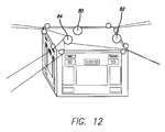
- Figure 12 is a close-up perspective reeving diagram of the top of the scoreboard as shown in Figs. 10 and 11 .
- Embodiments of the invention move the object throughout a three-dimensional space by using one or two lines.
- Embodiments that utilize two lines may be converted to embodiments that utilize one line by coupling the two lines at the Z movement device for example. As all embodiments may utilize one or two lines, for ease of illustration the two line embodiments will be described.
- the two lines are moved by rotating drum winches that are driven by motors in one or more embodiments. One line controls the X-axis motion of the object and the second line controls the Y-axis motion of the object.
- the object is moved in the Z-axis direction in one embodiment by rotation of a Z-axis drum winch that controls movement of both the X-axis line and Y-axis line to raise and lower the object.
- a Z-axis drum winch that controls movement of both the X-axis line and Y-axis line to raise and lower the object.
- numerous specific details are set forth to provide a more thorough description of embodiments of the invention. It will be apparent, however, to one skilled in the art, that the invention may be practiced without these specific details and well known features have not been described in detail so as not to obscure the invention.
- the first and second lines that control movement in the X and Y axis are coupled at Z movement device 84 as shown in Figure 1 and form one line. Although they are still termed X and Y lines in a one line embodiment, they are simply two sides of one line.
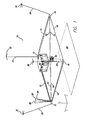
- Figure 1 shows a perspective view of one embodiment of system 10.
- the three axes are shown in Figure 1 with the X-axis, Y-axis and Z-axis.
- the X-axis and Y-axis designate generally orthogonal horizontal directions and the Z-axis designates the vertical direction.
- support rope 12, support rope 14, support rope 16 and support rope 18 are configured to surround the perimeter of an area of interest such as court 40 as shown in Figure 1 .
- Support ropes 12, 14, 16 and 18 are attached to anchor rope 20, anchor rope 22, anchor rope 24 and anchor rope 26 as shown in Figure 1 .
- Support rope is another name for support line and support lines 12, 14, 16 and 18 may be rigid or flexible for example. Corners 70, 72, 74 and 76 may be weighted to keep support lines 12, 14, 16 and 18 relatively straight.
- Anchor ropes 20, 22, 24 and 26 are further attached to a selected series of anchor points 30, 32, 34 and 36 as shown schematically in Figure 1 .
- Anchor points 30, 32, 34 and 36 may be located at distant supporting structures such as support columns, girders, and other man made or natural structural formations that can provide sufficient support and anchorage.
- Figure 1 shows four anchor points 30, 32, 34 and 36, but it is understood and it is within the scope of the present invention that a different number of anchor points can be utilized and that anchor ropes 20, 22, 24 and 26 may share one or more anchor points.
- an embodiment employing at least three anchor points allows for non-linear three-dimensional coverage.
- support rope 12, support rope 14, support rope 16 and support rope 18 are positioned in a substantially planar configuration in the X-axis and Y-axis plane as shown in Figure 1 .
- Alternative configurations, including non-planar arrangements of the support ropes, are within the scope of the invention.
- support rope 12, support rope 14, support rope 16 and support rope 18 are positioned in an approximate Z-axis position as illustrated in Figure 1 below the bottom of an obstruction, which as shown in Figure 1 is a scoreboard 42.
- X line side and Y line side of the single support line is hence equal between the support points, here the corners.
- object 50 is supported by and moved in three dimensions by two lines, X movement line 52 and Y-movement line 54.
- X movement line 52 and Y-movement line 54 may be coupled at the Z movement device to allow for a one line embodiment.
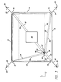
- Figure 2 shows the reeving for X-movement line 52 and Y movement line 54.
- X-movement line 52 moves object 50 through sheave 62 and sheave 66 and Y-movement line 54 moves object 50 through sheave 60 and sheave 64.
- Each of the lines 52 and 54 forms a pair of "V' shapes on opposing sides of the object 50 when viewed from above as in Figure 2 .
- object 50 provides a mobile attachment point for cameras, video equipment, wireless communication devices, mining scoops, logging hooks or the like, and can be used for many different tasks that require a movable platform.
- X-movement line 52 is reeved through a series of pulleys located as indicated in Figure 2 at corner 70, corner 72, corner 74 and corner 76 and coupled to X-axis drum winch 80 configured to intake line on one side and eject line on another, shown in Figure 1 adjacent to corner 70.
- Y-movement line 54 is reeved through a series of pulleys located as indicated in Figure 2 at corner 70, corner 72, corner 74 and corner 76 and coupled to Y-axis drum winch 82 configured to intake line on one side and eject line on another, also shown in Figure 1 .
- Both X-axis drum winch 80 and Y drum winch 82 may be implemented as "bull wheels" that each move one side of line from one side of object 50 to the other side. As the sheaves coupled to the object being supported that are not having line injected or extracted to them simply rotate, relatively independent motion in the X and Y axes is achieved.
- object 50 By rotating X-axis drum winch 80, object 50 can be moved in the X direction for example, toward support rope 14 or toward support rope 18 as shown in Figure 2 .
- Y-axis drum winch 82 By rotating Y-axis drum winch 82, the object 50 is moved in the Y direction for example, toward support rope 12 or toward support rope 16 in Figure 2 .
- Figure 3 shows movement of object 50 having been moved by X-axis drum winch 80 and Y-axis drum winch 52 in both the X direction and Y direction from the position of object 50 shown in Figure 2 .
- Z-axis drum winch 84 is coupled to both X-movement line 52 and Y-movement line 54.
- Z-axis drum winch 84 also known as the Z movement device provides a coupling point for coupling X-movement line 52 to Y-movement line 54 either on one end (to provide a large two ended line) or by coupling both ends of each line to one another (to provide a large line loop with no ends).
- object 50 is moved toward scoreboard 42, or upward in the Z-direction as shown in the embodiment in Figure 1 .
- object 50 can be moved toward court 40, or downward in the Z-direction as in Figure 1 . See Fig. 12 and associated description further in this paper regarding the X and Y shifting of line from one side of the supported object to the other and the Z intake or output of line for raising or lowering the object.
- motors and drive pulleys that move X-axis drum winch 80, Y-axis drum winch 82 and Z-axis drum winch 84 are not shown for ease of illustration.
- the parent applications incorporated by reference at the beginning of this disclosure provide alternative reevings that may be utilized with embodiments of the invention described herein for example.
- Motors along with their associated drive pulleys and drum winches that minimize rope wear and provide anti-derailing features can be used to drive the lines.
- the motors may comprise stepping motors or standard motors with brake systems in order to lock motion when the motors have stopped operating.
- the control of the motors for drum winches 80, 82 and 84 can be in the form of simple switches or a computer system that takes into account the Z-axis position of object 50 to keep object 50 in a substantially constant Z-axis position while traversing the X-axis and or the Y-axis such as shown in Figures 2 and 3.
- Figure 3 shows supported object 50 moved to the lower right corner of the drawing by injecting X support line 52 into sheave 62 and out of sheave 66, while Y axis movement is performed by injecting Y support line 54 into sheave 60 and out of sheave 64.
- this description utilizes X and Y support lines they may also be coupled together at the Z movement device to form two line sides of a single line.
- X-movement line 52 and Y-axis movement line 54 comprise 1/8 inch Tech 12 synthetic rope and other line sizes, dimensions and materials are within the scope of the invention.
- support ropes 12, 14, 16 and 18 comprise 1/4 inch Tech 12 rope and other materials, sizes and dimensions of lines or ropes are within the scope of the invention.
- the invention is not limited to a system with a rectangular configuration or to a set number of support ropes or anchor ropes.
- the invention can be adapted to surround areas of various shapes, including triangular embodiments as shown in Figure 4 , quadrilateral embodiments and embodiments where the area is of an irregular shape or is comprised of curved shapes.
- the anchor points for the anchor ropes need not be positioned equidistant from each other but can be located where sufficient anchorage can be found.
- object 50 can be moved over the entire area of interest, here court 40, so that object 50, X-movement line 52 and Y-movement line 54 do not contact an obstruction such as the scoreboard 42 within the three-dimensional space above the area of interest but remain under the scoreboard 42.
- corner 70, corner 72, corner 74 and corner 76 are located at a Z-axis position that is approximately the same Z-axis position as the bottom of the scoreboard 42.
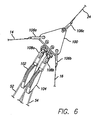
- Figure 6 shows one embodiment of a corner such as corner 74.
- support rope 14 is coupled to plate 100 by connector 106a and support rope 16 is coupled to plate 100 by connector 106b.
- Plate 100 is shown in a substantially triangular configuration, but other configurations are within the scope of the invention.
- Support rope 24 is coupled to plate 100 by connector 106c.
- the connectors 106 are shown as generally shaped as removable U-bolt connectors in Figure 6 but other types of connectors known in the art are within the scope of the invention.
- Support rope 24 may be disconnected at connector 106c to allow for storage of the support lines for quick disassembly.
- support rope 24 may be coupled with a winch to allow for releasing tension while applying tension may be utilized to put the support rope back into place for use, for example when a game occurs in the area beneath the supported object.
- tension may be utilized to put the support rope back into place for use, for example when a game occurs in the area beneath the supported object.
- X-movement line 52 is reeved through sheave 102 attached to plate 100 by shackle 108a as shown in Figure 6 .
- Y-movement line 54 is reeved through sheave 104 that is secured to plate 100 by shackle 108b also as shown in Figure 6 .
- sheave 102 and sheave 104 are high speed pulleys.
- additional sheaves are utilized at a corner where X-movement line 52 or Y-movement line 54 is reeved a multiple number of times to a particular corner. Further, additional plates can be utilized at a corner with multiple sheaves.
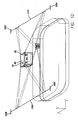
- FIG. 7 shows an embodiment of an anchorage for the invention.
- Anchor line 24 is secured to structure 120 which, in this embodiment is a support structure component such as used for a convention hall or arena.
- anchor line 24 is coupled to tensioner 122 which is then secured to structure 120.
- tensioner 122 is a manually operated tensioning device. By an appropriate number of hand cranks on handle 122a of tensioner 122, tension is imparted to anchor line 24 and also to one or more support ropes 12, 14, 16 and 18 in system 10.
- Figure 8 shows one embodiment of the invention that includes camera 130 coupled to self-leveling apparatus 132.
- self-leveling apparatus 132 includes connector 134 which is of a "W" configuration and is attached to sheave 62 by first shackle 140 and is attached to sheave 66 by second shackle 140.
- Self-leveling apparatus 132 also includes second connector 136 which is attached to sheave 60 by third shackle 140 and is attached to sheave 64 by fourth shackle 140.
- Self-leveling apparatus 132 is coupled to rod 138a which is attached to harness 138b that supports camera 130.
- apparatus 132 can pivot about connector pin 142, for X-axis movement, and can pivot about connector pin 144, for Y axis movement.
- Such pivoting motion allows camera 130 to remain substantially level and without unwanted swaying motion that could adversely impact picture quality from the camera.
- the weight of camera 130 aids in maintaining the self-leveling apparatus 132 in a substantially level arrangement by the downward or Z direction weight of camera 130.
- Figure 9 shows an embodiment where camera 130 includes power source 150.
- power source 150 may include a battery, several batteries and other power sources known in the art for powering electrical devices and include embodiments with a generator or other portable power source.
- Wireless transceivers may also be utilized or coupled with camera 130.
- sheaves 60, 62, 64 and 66 may include generators to inductively charge power source 150 for example a battery when line moves through the sheaves.
- Figure 10 is a perspective view of an embodiment employing two support lines from which to couple at least three anchor points that in turn couple with the movement line(s).
- the support lines are horizontally configured to support line movement sheaves.
- Support line 1000 for example support two sets of redirection sheaves for redirecting X movement line and Y movement line each.
- X-axis drum winch 80 here a bull wheel is utilized to shift X movement line from the left side of the figure to the right side of the figure and visa versa.
- Y-axis drum winch 82 is utilized to shift Y movement line from the front of the figure to the back and visa versa to allow for motion of the camera shown from the front and back of the figure.
- Figure 11 is a perspective view of an embodiment employing 2 horizontal support lines from which to couple at least three anchor points that in turn couple with the movement line(s).
- sheaves 1050-1053 operate identically to those of Fig. 10 , wherein line moved by a particular line movement device is injected into one side of the camera while being extracted from the other side results in motion towards the extracted line.
- line moved by a particular line movement device is injected into one side of the camera while being extracted from the other side results in motion towards the extracted line.
- X movement line is injected into sheave 1053 and removed from 1051, then the camera moves to the left in the figure, while line simply rolls through sheaves 1050 and 1052.
- there is no Y motion motion into our out of the written page as the camera moves in the X-axis.
- Figure 12 is a close-up perspective reeving diagram of the top of the scoreboard as shown in Figs. 10 and 11 .
- X-axis drum winch 80 (here implemented as a bull wheel) simply redirects X movement line from the left side of Figure 11 to the right side and visa versa. This is shown as the line that couples to the upper left sheave (shown as a small circle in the top left of the scoreboard) to X-axis drum winch 80 to the upper right sheave (shown as a small circle in the top right of the scoreboard). This results in X-axis movement.
- Movement of Y-axis drum winch 82 (here implemented as a bull wheel) to extract line from one side of the camera and inject line to the other side of the camera results in Y-axis movement. For example, this is shown as the line that passes through the right upper sheave then through Y-axis drum winch 82 then through the right lower sheave.
- X and Y movement only X and Y movement line couples to the X and Y-axis drums respectively.
- rotation of Z movement device 84 that is coupled to both ends of X movement line and both ends of Y movement line results in Z-axis movement without substantial movement of the supported object in X or Y axes.
- the bottom left of the scoreboard is coupled with two sheaves that allow for both X and Y movement line to travel to Z movement device 84 and in addition the bottom right sheave and the left upper sheave allow for X and Y movement line respectively to travel to and from Z movement device 84.
- Z movement device 84 couples to two sides of X movement line and two sides of Y movement line.
- the lines may be coupled to one another resulting in either one longer line with two ends or if both ends of both lines are coupled to one another, then one long looped movement line results.
- each movement line may have its ends coupled to its other end, resulting in one or both lines being looped or two ended. Regardless of the coupling method at the Z movement device, X, Y and Z movement is accomplished as previously described.
- redirection sheaves at the top of the scoreboard and the various movement devices and bull wheels are shown coupled to the scoreboard, they may be place absolutely anywhere available in three-dimensional space. For example, running the lines up to a cat walk or other support structure for collocation of the various motors, drives and movement devices is in keeping with the spirit of the invention.
Abstract
Uses line(s) to enable movement of an object through three-dimensional space having clearance limitations or obstructions over an area. Does not require large nearby support structures. The object (50) coupled with the movement line(s) is/are supported by at least three support lines (12,14,16) that are arranged about a perimeter of the area. The support system can enclose any area size or shape. Uses motorized line movement device to displace the lines in a direction determined by the rotation of the line movement devices (80,84,82). The lines are reeved through pulleys attached to the support rope system which direct the lines to the appropriate line movement devices. By appropriate reeving, the object can be controllably moved in three axes that are not required to be orthogonal using one or two lines.
Description
- This application claims benefit of United States Provisional
Patent application 60/893,362 filed March 6, 2007 U.S. Patent Application Serial No. 11/556,264 filed on November 3, 2006 U.S. Patent Application Serial No. 11/251,439, filed on October 15, 2005 U.S. Patent Application Serial No. 10/709,944, filed on June 8, 2004 U.S. Patent No. 6,975,089 ; which is a continuation in part ofU.S. Patent Application Serial No. 10/708,158, filed on February 12, 2004 U.S. Patent No. 7,088,071 ; which is a continuation in part ofU.S. Patent Application Serial No. 10/604,525 filed on July 28, 2003 U.S. Patent No. 6,809,495 , the specifications of which are incorporated herein by this reference. - The invention relates to a system and method for moving an object through three-dimensional space by lines supported on a rope assembly and is more particularly, but not by way of limitation, directed to a system and method by which an object is controllably moved through three-dimensional space with obstructions and limited clearance with a adaptable rope support system.
- An aerial cable rail system is a system based on an elevated cable or rope along which objects are transported. Existing cable rail systems rely on large fixed structures or complex control systems in order to facilitate the movement of objects. Such systems are impractical or difficult to use in applications that require both a steady platform during movement and do not have, or cannot utilize, large supporting structures that would obstruct the view of customers or fans say, for example, at an indoor sporting event. The conventional systems typically fail to satisfactorily achieve the full spectrum of ease of control, ease of transport, speed and adaptability for demanding applications.
- In
U.S. Patent No. 4,625,938 , an invention is disclosed in which a camera payload can be moved within three-dimensional space. However, this patent also shows four large support structures that are used to support the payload in the invention. Thus, this system does not provide adaptability to venues where such support structures are not available or cannot be used. - In
U.S. Patent No. 5,585,707 , a system is shown in which a robot or person can be moved within a three-dimensional space. The payload is limited and the support structure is of a small scale. If the structure were to be scaled up, obstacles such as scoreboards, goal posts or light poles would inhibit the motion of the payload through a path between two points defined within the cube shown in this patent, since there are so many wires required to practice the invention. Also, the invention would not appear to allow the Z-axis to vary beneath the cube, and the size of the cube support structure to service a large volume of space would be extremely expensive to build on the scale required for use in stadiums, convention centers or arenas and would obstruct views of patrons at these events. - In
U.S. Patent No. 5,568,189 , another system is disclosed for moving cameras in three dimensional space. The problems with the system disclosed become apparent when the scale of the system is enlarged.Figure 4 ofU.S. Patent 5,568,189 shows how two parallel highline cables sag inward when the payload is in the middle of the X, Y space. Since the system does not use strong rails to support the Y-axis rope, the weight bearing of the system is dependent upon the strength of the building or structure in which it is mounted and the springs in its weight bearing X-axis connectors. The motors for the various axes are mounted up in the rigging, which would require multiple extremely long power cables to traverse the volume of space along with the payload if the system were modified for outdoor use. Moreover, the size of the motors limits the payload that can be carried, and further limits the speed at which the payload can be carried. - Thus, a need exists for an improved system and method for controlling movement of an object through a three-dimensional space having obstructions and limited clearance without using close-in, view obstructing structures to support the object and its related equipment.
- One or more embodiments of the invention are directed to a system and method for moving an object through a three-dimensional space using lines and a rope support system. Embodiments of the invention, for example, may be used for sporting events, concerts or any other activity that benefits from movement of a camera or other object to any position within a three-dimensional space. Further objects are directed to a system and method for moving an object through a three-dimensional space with minimal clearances or obstacles located in the space that are to be avoided while also maintaining minimum heights for the object and its control lines. Additional objects of the invention are directed to a system and method for moving an object through a three-dimensional space without using large support structures that can obstruct or block views of customers particularly at sporting events. Movement of the object using embodiments of the invention includes displacement of the object in the horizontal X and Y directions and displacement in the vertical or Z direction.
- In one embodiment, an object is moved through a three-dimensional space over an area by lines attached to the object and coupled to line movement devices. Support is provided by at least a first support rope, a second support rope and a third support rope that are arranged about the perimeter of the area to provide a flexible support system for the object. The support system is adapted to enclose any area size or shape and can be adapted so that the object and its control lines do not contact obstructions during movement within the three-dimensional space of interest. The lines are coupled to the object and appropriate motorized line movement devices to displace the lines in a direction determined by the rotation of the line movement devices. The flexible lines are reeved through pulleys attached to the support rope system which direct the lines to the appropriate line movement devices. By appropriate reeving, the object can be moved in three orthogonal directions with two lines and motorized line movement devices so the object is controllably moved within an entire three-dimensional space of interest. In another embodiment, the two movement lines are connected at the Z movement device yielding a system that is configured to move an object in three dimensions via one line.
- In one embodiment, the object includes a camera which includes a live video camera, a wireless camera and other electrical, mechanical and optical equipment, including a still camera, audio recording equipment and other types of recording or sensing devices in addition to live feed cameras used to capture live images. In further embodiments, the object includes a power source and may include a battery, a generator or other sources of power as required for particular applications. In one embodiment, the object includes a self-leveling apparatus so that in certain uses, such as for a camera or other equipment, the object remains substantially level during movement of the object so picture image and quality are not adversely impacted by unwanted swaying or unwanted movement of the camera. The self-leveling apparatus may be active, meaning that power is utilized to actively stabilize the camera. Conversely, the self-leveling apparatus may be passive, meaning that non-powered dampening devices configured to provide resistance to movement are utilized to limit or prevent swinging of the camera.
- In one embodiment, tension is applied to one or more of the anchor ropes and thus the entire system of support ropes by a tensioning device that is either manually operated or in one or more embodiments, is operated by any known powered means. In an embodiment, the movement of the object and the lines coupled to the object is controlled to substantially avoid contact with obstructions located within the three-dimensional space of interest, such as, for example, a scoreboard at an indoor arena.
- In one or more embodiments, the type of line embodiments of the invention that are utilized include synthetic rope fibers such as, but not limited to, HMDPE (High Molecular Density Polyethylene) fibers such as Spectra, or improved fibers such as Vectran and include 1/8 inch Tech 12 synthetic rope. In one or more embodiments, the support ropes are 1/4 inch Tech 12 support rope. Other and further advantages will appear to persons skilled in the art from the figures and description provided herein.
- The above and other aspects, features and advantages of the invention will be more apparent from the following more particular description thereof, presented in conjunction with the following drawings wherein:
-
Figure 1 is a perspective schematic view of one embodiment of the invention illustrating the support ropes and flexible lines. -
Figure 2 is a top view of one embodiment of the invention showing the support ropes and flexible lines. -
Figure 3 is a top view of an embodiment of the invention illustrating an aspect of the invention. -
Figure 4 is another top view of one embodiment of the invention with three support ropes. -
Figure 5 is a side elevation view illustrating another embodiment of the invention showing the object and an obstruction in the three-dimensional space. -
Figure 6 is a perspective view showing an embodiment of a corner of the support ropes. -
Figure 7 is a perspective view of the tensioning device for the support ropes in one embodiment of the invention. -
Figure 8 is a side elevation view of a self-leveling apparatus and a camera used in one or more embodiments of the invention. -
Figure 9 is a side elevation view of another embodiment of a camera and a power source for the camera used in one or more embodiments of the invention. -
Figure 10 is a perspective view of an embodiment employing 2 horizontal support lines from which to couple at least three anchor points that in turn couple with the movement line(s). -
Figure 11 is a perspective view of an embodiment employing 2 horizontal support lines from which to couple at least three anchor points that in turn couple with the movement line(s). -
Figure 12 is a close-up perspective reeving diagram of the top of the scoreboard as shown inFigs. 10 and11 . - A system for movement of an object throughout a three-dimensional space by lines and a rope support system will now be described. Embodiments of the invention move the object throughout a three-dimensional space by using one or two lines. Embodiments that utilize two lines may be converted to embodiments that utilize one line by coupling the two lines at the Z movement device for example. As all embodiments may utilize one or two lines, for ease of illustration the two line embodiments will be described. The two lines are moved by rotating drum winches that are driven by motors in one or more embodiments. One line controls the X-axis motion of the object and the second line controls the Y-axis motion of the object. The object is moved in the Z-axis direction in one embodiment by rotation of a Z-axis drum winch that controls movement of both the X-axis line and Y-axis line to raise and lower the object. In the following description, numerous specific details are set forth to provide a more thorough description of embodiments of the invention. It will be apparent, however, to one skilled in the art, that the invention may be practiced without these specific details and well known features have not been described in detail so as not to obscure the invention. For example, in a one line embodiment, the first and second lines that control movement in the X and Y axis are coupled at
Z movement device 84 as shown inFigure 1 and form one line. Although they are still termed X and Y lines in a one line embodiment, they are simply two sides of one line. -
Figure 1 shows a perspective view of one embodiment ofsystem 10. The three axes are shown inFigure 1 with the X-axis, Y-axis and Z-axis. The X-axis and Y-axis designate generally orthogonal horizontal directions and the Z-axis designates the vertical direction. There is no requirement that the axes be orthogonal though so long as the sheaves supporting the two line sides are near each other at each support. Hence, any geometry is thus configured. In this embodiment,support rope 12,support rope 14,support rope 16 andsupport rope 18 are configured to surround the perimeter of an area of interest such ascourt 40 as shown inFigure 1 .Support ropes rope 20,anchor rope 22,anchor rope 24 andanchor rope 26 as shown inFigure 1 . Support rope is another name for support line andsupport lines Corners support lines -
Anchor ropes Figure 1 . Anchor points 30, 32, 34 and 36 may be located at distant supporting structures such as support columns, girders, and other man made or natural structural formations that can provide sufficient support and anchorage.Figure 1 shows four anchor points 30, 32, 34 and 36, but it is understood and it is within the scope of the present invention that a different number of anchor points can be utilized and thatanchor ropes - In one embodiment,
support rope 12,support rope 14,support rope 16 andsupport rope 18 are positioned in a substantially planar configuration in the X-axis and Y-axis plane as shown inFigure 1 . Alternative configurations, including non-planar arrangements of the support ropes, are within the scope of the invention. In one embodiment,support rope 12,support rope 14,support rope 16 andsupport rope 18 are positioned in an approximate Z-axis position as illustrated inFigure 1 below the bottom of an obstruction, which as shown inFigure 1 is ascoreboard 42. As long as the two line sides are located near one another at each support point any three dimensional non-planar configuration is thus achieved since the total amount of X line and total amount of Y line from each support point to the object being supported is relatively equal regardless of the position of the object. For one line embodiments, X line side and Y line side of the single support line is hence equal between the support points, here the corners. - As shown in
Figure 2 , object 50 is supported by and moved in three dimensions by two lines,X movement line 52 and Y-movement line 54.X movement line 52 and Y-movement line 54 may be coupled at the Z movement device to allow for a one line embodiment.Figure 2 shows the reeving forX-movement line 52 andY movement line 54.X-movement line 52 moves object 50 throughsheave 62 andsheave 66 and Y-movement line 54 moves object 50 throughsheave 60 andsheave 64. Each of thelines object 50 when viewed from above as inFigure 2 . In one or more embodiments, object 50 provides a mobile attachment point for cameras, video equipment, wireless communication devices, mining scoops, logging hooks or the like, and can be used for many different tasks that require a movable platform. -
X-movement line 52 is reeved through a series of pulleys located as indicated inFigure 2 atcorner 70,corner 72,corner 74 andcorner 76 and coupled toX-axis drum winch 80 configured to intake line on one side and eject line on another, shown inFigure 1 adjacent to corner 70. Y-movement line 54 is reeved through a series of pulleys located as indicated inFigure 2 atcorner 70,corner 72,corner 74 andcorner 76 and coupled to Y-axis drum winch 82 configured to intake line on one side and eject line on another, also shown inFigure 1 . BothX-axis drum winch 80 andY drum winch 82 may be implemented as "bull wheels" that each move one side of line from one side ofobject 50 to the other side. As the sheaves coupled to the object being supported that are not having line injected or extracted to them simply rotate, relatively independent motion in the X and Y axes is achieved. - By rotating
X-axis drum winch 80, object 50 can be moved in the X direction for example, towardsupport rope 14 or towardsupport rope 18 as shown inFigure 2 . By rotating Y-axis drum winch 82, theobject 50 is moved in the Y direction for example, towardsupport rope 12 or towardsupport rope 16 inFigure 2 .Figure 3 shows movement ofobject 50 having been moved byX-axis drum winch 80 and Y-axis drum winch 52 in both the X direction and Y direction from the position ofobject 50 shown inFigure 2 . - In further embodiments, Z-
axis drum winch 84, as shown inFigure 1 , is coupled to bothX-movement line 52 and Y-movement line 54. In the one line embodiment, Z-axis drum winch 84 also known as the Z movement device provides a coupling point for couplingX-movement line 52 to Y-movement line 54 either on one end (to provide a large two ended line) or by coupling both ends of each line to one another (to provide a large line loop with no ends). By decreasing the length of each of theX-movement line 52 and Y-movement line 54 in thesystem 10 by movement of Z-axis drum winch 84,object 50 is moved towardscoreboard 42, or upward in the Z-direction as shown in the embodiment inFigure 1 . By instead increasing the length of each ofX-movement line 52 and Y-movement line 54 intosystem 10 by appropriate movement of Z-axis drum winch 84, object 50 can be moved towardcourt 40, or downward in the Z-direction as inFigure 1 . SeeFig. 12 and associated description further in this paper regarding the X and Y shifting of line from one side of the supported object to the other and the Z intake or output of line for raising or lowering the object. - For purposes of this disclosure, the motor or motors and drive pulleys that move
X-axis drum winch 80, Y-axis drum winch 82 and Z-axis drum winch 84 are not shown for ease of illustration. The parent applications incorporated by reference at the beginning of this disclosure provide alternative reevings that may be utilized with embodiments of the invention described herein for example. Motors along with their associated drive pulleys and drum winches that minimize rope wear and provide anti-derailing features can be used to drive the lines. The motors may comprise stepping motors or standard motors with brake systems in order to lock motion when the motors have stopped operating. The control of the motors for drum winches 80, 82 and 84 can be in the form of simple switches or a computer system that takes into account the Z-axis position ofobject 50 to keepobject 50 in a substantially constant Z-axis position while traversing the X-axis and or the Y-axis such as shown inFigures 2 and3. Figure 3 shows supportedobject 50 moved to the lower right corner of the drawing by injectingX support line 52 intosheave 62 and out ofsheave 66, while Y axis movement is performed by injectingY support line 54 intosheave 60 and out ofsheave 64. Although this description utilizes X and Y support lines they may also be coupled together at the Z movement device to form two line sides of a single line. - In one or more embodiments,
X-movement line 52 and Y-axis movement line 54 comprise 1/8inch Tech 12 synthetic rope and other line sizes, dimensions and materials are within the scope of the invention. In other embodiments,support ropes inch Tech 12 rope and other materials, sizes and dimensions of lines or ropes are within the scope of the invention. The invention is not limited to a system with a rectangular configuration or to a set number of support ropes or anchor ropes. The invention can be adapted to surround areas of various shapes, including triangular embodiments as shown inFigure 4 , quadrilateral embodiments and embodiments where the area is of an irregular shape or is comprised of curved shapes. The anchor points for the anchor ropes need not be positioned equidistant from each other but can be located where sufficient anchorage can be found. - As illustrated in
Figure 5 , object 50 can be moved over the entire area of interest, herecourt 40, so thatobject 50,X-movement line 52 and Y-movement line 54 do not contact an obstruction such as thescoreboard 42 within the three-dimensional space above the area of interest but remain under thescoreboard 42. In one or more embodiments,corner 70,corner 72,corner 74 andcorner 76 are located at a Z-axis position that is approximately the same Z-axis position as the bottom of thescoreboard 42. -
Figure 6 shows one embodiment of a corner such ascorner 74. In this embodiment,support rope 14 is coupled toplate 100 byconnector 106a andsupport rope 16 is coupled toplate 100 byconnector 106b.Plate 100 is shown in a substantially triangular configuration, but other configurations are within the scope of the invention.Support rope 24 is coupled toplate 100 byconnector 106c. The connectors 106 are shown as generally shaped as removable U-bolt connectors inFigure 6 but other types of connectors known in the art are within the scope of the invention.Support rope 24 may be disconnected atconnector 106c to allow for storage of the support lines for quick disassembly. Alternatively,support rope 24 may be coupled with a winch to allow for releasing tension while applying tension may be utilized to put the support rope back into place for use, for example when a game occurs in the area beneath the supported object. By allowing for all but one of the support lines to disconnect or release, the remaining support lines and movement lines may be stored near the support line that does not release for example. Rapid storage and deployment is thus achieved. -
X-movement line 52 is reeved throughsheave 102 attached to plate 100 by shackle 108a as shown inFigure 6 . Y-movement line 54 is reeved throughsheave 104 that is secured to plate 100 byshackle 108b also as shown inFigure 6 . In one or more embodiments,sheave 102 and sheave 104 are high speed pulleys. In various embodiments, additional sheaves are utilized at a corner whereX-movement line 52 or Y-movement line 54 is reeved a multiple number of times to a particular corner. Further, additional plates can be utilized at a corner with multiple sheaves. -
Figure 7 shows an embodiment of an anchorage for the invention.Anchor line 24 is secured to structure 120 which, in this embodiment is a support structure component such as used for a convention hall or arena. In one embodiment,anchor line 24 is coupled totensioner 122 which is then secured to structure 120. In this embodiment,tensioner 122 is a manually operated tensioning device. By an appropriate number of hand cranks onhandle 122a oftensioner 122, tension is imparted to anchorline 24 and also to one ormore support ropes system 10. -
Figure 8 shows one embodiment of the invention that includescamera 130 coupled to self-levelingapparatus 132. In this embodiment, self-levelingapparatus 132 includesconnector 134 which is of a "W" configuration and is attached to sheave 62 byfirst shackle 140 and is attached to sheave 66 bysecond shackle 140. Self-levelingapparatus 132 also includessecond connector 136 which is attached to sheave 60 bythird shackle 140 and is attached to sheave 64 byfourth shackle 140. Self-levelingapparatus 132 is coupled torod 138a which is attached to harness 138b that supportscamera 130. - During movement of self-leveling
apparatus 132 byX-movement line 52 or Y-movement line 54,apparatus 132 can pivot aboutconnector pin 142, for X-axis movement, and can pivot aboutconnector pin 144, for Y axis movement. Such pivoting motion allowscamera 130 to remain substantially level and without unwanted swaying motion that could adversely impact picture quality from the camera. In one or more embodiments, the weight ofcamera 130 aids in maintaining the self-levelingapparatus 132 in a substantially level arrangement by the downward or Z direction weight ofcamera 130. -
Figure 9 shows an embodiment wherecamera 130 includespower source 150. In one or more embodiments,power source 150 may include a battery, several batteries and other power sources known in the art for powering electrical devices and include embodiments with a generator or other portable power source. Wireless transceivers may also be utilized or coupled withcamera 130. In addition, sheaves 60, 62, 64 and 66 (seeFig. 8 as well) may include generators to inductivelycharge power source 150 for example a battery when line moves through the sheaves. -
Figure 10 is a perspective view of an embodiment employing two support lines from which to couple at least three anchor points that in turn couple with the movement line(s). The support lines are horizontally configured to support line movement sheaves.Support line 1000 for example support two sets of redirection sheaves for redirecting X movement line and Y movement line each.X-axis drum winch 80, here a bull wheel is utilized to shift X movement line from the left side of the figure to the right side of the figure and visa versa. Y-axis drum winch 82 is utilized to shift Y movement line from the front of the figure to the back and visa versa to allow for motion of the camera shown from the front and back of the figure. AssertingZ movement device 84 here a winch in one direction wherein Z movement device is coupled to both X movement line and Y movement line (or X and Y line sides in one line embodiments) results in vertical displacement up while rotation of Z movement device in the other direction results in the opposite vertical displacement. -
Figure 11 is a perspective view of an embodiment employing 2 horizontal support lines from which to couple at least three anchor points that in turn couple with the movement line(s). In addition, sheaves 1050-1053 operate identically to those ofFig. 10 , wherein line moved by a particular line movement device is injected into one side of the camera while being extracted from the other side results in motion towards the extracted line. Hence if X movement line is injected intosheave 1053 and removed from 1051, then the camera moves to the left in the figure, while line simply rolls throughsheaves -
Figure 12 is a close-up perspective reeving diagram of the top of the scoreboard as shown inFigs. 10 and11 . Specifically, X-axis drum winch 80 (here implemented as a bull wheel) simply redirects X movement line from the left side ofFigure 11 to the right side and visa versa. This is shown as the line that couples to the upper left sheave (shown as a small circle in the top left of the scoreboard) toX-axis drum winch 80 to the upper right sheave (shown as a small circle in the top right of the scoreboard). This results in X-axis movement. Movement of Y-axis drum winch 82 (here implemented as a bull wheel) to extract line from one side of the camera and inject line to the other side of the camera results in Y-axis movement. For example, this is shown as the line that passes through the right upper sheave then through Y-axis drum winch 82 then through the right lower sheave. Hence for X and Y movement, only X and Y movement line couples to the X and Y-axis drums respectively. However, for Z axis movement, rotation ofZ movement device 84 that is coupled to both ends of X movement line and both ends of Y movement line results in Z-axis movement without substantial movement of the supported object in X or Y axes. For example, the bottom left of the scoreboard is coupled with two sheaves that allow for both X and Y movement line to travel toZ movement device 84 and in addition the bottom right sheave and the left upper sheave allow for X and Y movement line respectively to travel to and fromZ movement device 84. HenceZ movement device 84 couples to two sides of X movement line and two sides of Y movement line. Alternatively, the lines may be coupled to one another resulting in either one longer line with two ends or if both ends of both lines are coupled to one another, then one long looped movement line results. Furthermore, each movement line may have its ends coupled to its other end, resulting in one or both lines being looped or two ended. Regardless of the coupling method at the Z movement device, X, Y and Z movement is accomplished as previously described. - Although the redirection sheaves at the top of the scoreboard and the various movement devices and bull wheels are shown coupled to the scoreboard, they may be place absolutely anywhere available in three-dimensional space. For example, running the lines up to a cat walk or other support structure for collocation of the various motors, drives and movement devices is in keeping with the spirit of the invention.
- Thus, a system for movement of an object through a three-dimensional space has been disclosed and described. While embodiments and alternatives have been disclosed and discussed, the invention herein is not limited to the particular disclosed embodiments or alternatives and the invention need not include all of the features described herein. The claims herein are what define the metes and bounds of the invention and include the full breadth and scope of all equivalents.
Claims (15)
- A system for controlling movement of an object through three-dimensional space comprising:an object adapted for three-dimensional movement over an area, said area comprising a perimeter, said perimeter defined by at least a first support rope and a second support rope wherein said at least said first and said second ropes are arranged to define at least a first corner, a second corner and a third corner adjacent said perimeter;a first line coupled with said object and with a first motorized line movement device configured to displace said first line in a direction determined by rotation of said first motorized line movement device;a first pulley attached to a first location proximate to said first corner and configured to redirect said first line as said first line passes through said first pulley to said third corner and said first motorized line movement device;a second line coupled with said object and with a second motorized line movement device configured to displace said second line in a direction determined by rotation of said second motorized line movement device;a second pulley attached to a second location proximate to said second corner and configured to redirect said second line as said second line passes through said second pulley to said third corner and said second motorized line movement device; anda Z movement device configured to displace said first line and said second line and move an object vertically as determined by rotation of said Z movement device.
- The system of claim 1 where said object comprises a camera.
- The system of claim 1 wherein said first line and said second line are two sides of a single line.
- The system of claim 1 where said object comprises a power source.
- The system of claim 1 wherein said second pulley is released to allow for storage of said first line and said second line.
- The system of claim 1 where said object comprises a self leveling apparatus.
- The system of claim 1 where tension is applied to one or more of said first support rope, said second support rope and said third support rope.
- The system of claim 7 where said tension is applied by a tensioning device.
- The system of claim 1 where movements of said object, said first line and said second line are controlled to avoid contact with one or more obstructions within said three-dimensional space.
- A system for controlling movement of an object through three-dimensional space comprising:an object adapted for three-dimensional movement over an area comprising a perimeter, said perimeter defined by support ropes, said support ropes arranged to define at least a first corner, a second corner and a third corner adjacent said perimeter;an X movement line coupled with said object and with an X movement device;a first pulley attached to a first location proximate to said first corner and configured to redirect said X movement line as said X movement line passes through said first pulley to said third corner and said X movement device;a Y movement line coupled with said object and with a Y movement device;a second pulley attached to a second location proximate to said second corner and configured to redirect said Y movement line as said Y movement line passes through said second pulley to said third corner and said Y movement device; anda Z movement device configured to move said X movement line and said Y movement line in unison, said Z movement device configured to control vertical movement of said object.
- The system of claim 10 where said object comprises a camera.
- The system of claim 10 wherein said first line and said second line are two sides of a single line.
- The system of claim 10 where said object comprises a power source.
- The system of claim 10 wherein said second pulley is released to allow for storage of said first line and said second line.
- A method for controlling movement of an object through three-dimensional space comprising:arranging support ropes about the perimeter of an area, said support ropes comprising at least a first corner, a second corner and a third corner adjacent said perimeter;coupling an X movement line to said object and to an X movement device;attaching a first pulley to a first location proximate to said first corner of said support ropes, said first pulley configured to redirect said X movement line as said X movement line passes through said first pulley to said third corner and said X movement device;coupling a Y movement line to said object and to a Y movement device;attaching a second pulley to a second location proximate to said second corner of said support ropes, said second pulley configured to redirect said Y movement line as said Y movement line passes through said second pulley to said third corner and said Y movement device; andconfiguring a Z movement device to move said X movement line and said Y movement line in unison to control vertical displacement of said object.
Applications Claiming Priority (3)
| Application Number | Priority Date | Filing Date | Title |
|---|---|---|---|
| US10/604,525 US6809495B2 (en) | 2003-07-28 | 2003-07-28 | System and method for moving objects within three-dimensional space |
| US89336207P | 2007-03-06 | 2007-03-06 | |
| US11/683,411 US20070152141A1 (en) | 2003-07-28 | 2007-03-07 | Line and rope system and method for movement of an object through three-dimensional space |
Publications (1)
| Publication Number | Publication Date |
|---|---|
| EP1967784A2 true EP1967784A2 (en) | 2008-09-10 |
Family
ID=42561224
Family Applications (1)
| Application Number | Title | Priority Date | Filing Date |
|---|---|---|---|
| EP08004178A Withdrawn EP1967784A2 (en) | 2003-07-28 | 2008-03-06 | Improved line and rope system and method for movement of an object through three-dimensional space |
Country Status (3)
| Country | Link |
|---|---|
| US (2) | US6809495B2 (en) |
| EP (1) | EP1967784A2 (en) |
| CA (1) | CA2624365A1 (en) |
Cited By (6)
| Publication number | Priority date | Publication date | Assignee | Title |
|---|---|---|---|---|
| CN102387959A (en) * | 2009-04-06 | 2012-03-21 | 三星重工业株式会社 | Tendon controlled mobile platform |
| WO2012112521A1 (en) * | 2011-02-15 | 2012-08-23 | Ftsi, Llc | Equipment movement system, process, and article |
| US10471590B1 (en) | 2019-04-08 | 2019-11-12 | Frédéric Vachon | Cable robot |
| CN111362138A (en) * | 2020-04-10 | 2020-07-03 | 三一海洋重工有限公司 | Tilting system and crane |
| DE102019201696A1 (en) * | 2019-02-11 | 2020-08-13 | Zf Friedrichshafen Ag | Control of a processing machine |
| US11865713B2 (en) | 2019-04-08 | 2024-01-09 | 10087530 Canada Inc. | Cable robot |
Families Citing this family (42)
| Publication number | Priority date | Publication date | Assignee | Title |
|---|---|---|---|---|
| DE10233875B4 (en) * | 2002-07-25 | 2008-08-14 | Siemens Ag | Crane system, in particular container crane |
| US6809495B2 (en) | 2003-07-28 | 2004-10-26 | Cablecam International Inc. | System and method for moving objects within three-dimensional space |
| US20070056463A1 (en) * | 2003-10-25 | 2007-03-15 | Jim Rodnunsky | Object movement system and method |
| US7520091B2 (en) * | 2004-07-09 | 2009-04-21 | Friedman Daniel B | Adaptable roof system |
| US20070064208A1 (en) * | 2005-09-07 | 2007-03-22 | Ablaze Development Corporation | Aerial support structure and method for image capture |
| US20100279255A1 (en) * | 2007-02-16 | 2010-11-04 | Ohio University | Vehicle simulator system |
| US7753642B2 (en) * | 2007-09-06 | 2010-07-13 | Ohio University | Apparatus and method associated with cable robot system |
| US20090103909A1 (en) * | 2007-10-17 | 2009-04-23 | Live Event Media, Inc. | Aerial camera support structure |
| WO2009105254A2 (en) * | 2008-02-20 | 2009-08-27 | Actioncam, Llc | Aerial camera system |
| US8402898B2 (en) * | 2008-06-09 | 2013-03-26 | Cablecam, Llc | Safety system and method for objects moved by a driving cabling system |
| DE102009012281B4 (en) | 2009-03-09 | 2014-04-03 | Audi Ag | Apparatus for moving a specimen and method for testing or characterizing driver's assistant systems |
| US8205835B2 (en) * | 2009-05-14 | 2012-06-26 | Wiley Jeremy A | Systems and methods for aerial cabled transportation |
| US8251597B2 (en) * | 2009-10-16 | 2012-08-28 | Wavecam Media, Inc. | Aerial support structure for capturing an image of a target |
| WO2011079122A1 (en) | 2009-12-23 | 2011-06-30 | Cablecam, Inc. | Apparatus and method for calibrating an aerial movement system |
| EP2580031B1 (en) * | 2010-06-08 | 2016-04-20 | Beckhoff Automation GmbH | Robot module |
| US9096294B1 (en) | 2011-06-20 | 2015-08-04 | The United States Of America As Represented By The Secretary Of The Navy | Trolley-payload inter-ship transfer system |
| US10469790B2 (en) * | 2011-08-31 | 2019-11-05 | Cablecam, Llc | Control system and method for an aerially moved payload system |
| US9337949B2 (en) | 2011-08-31 | 2016-05-10 | Cablecam, Llc | Control system for an aerially moved payload |
| GB2495908B8 (en) * | 2011-10-19 | 2017-06-14 | Vitec Group Plc | A camera support apparatus |
| US9921459B2 (en) * | 2011-11-02 | 2018-03-20 | Steven D. Wagner | Actively stabilized payload support apparatus and methods |
| US9048779B2 (en) * | 2013-04-19 | 2015-06-02 | Randall Lee Szarzynski | Multi-dimensional positioning of an object |
| KR102083193B1 (en) * | 2013-11-25 | 2020-03-02 | 삼성전자주식회사 | Robot cleaner |
| FR3029811B1 (en) * | 2014-12-16 | 2019-04-12 | Xavier Rocher | DEVICE AND METHOD FOR MANUFACTURING THREE DIMENSIONAL STRUCTURES CARRIED OUT IN SUCCESSIVE LAYERS |
| SI24932A (en) | 2015-02-20 | 2016-08-31 | Airnamics D.O.O. | A system for the moving of the platform and the useful cargo around the room with the use of robes and drums installed on the platform itself |
| DE102015002297B4 (en) * | 2015-02-23 | 2016-11-03 | MAX-PLANCK-Gesellschaft zur Förderung der Wissenschaften e.V. | Rope robot system for motion simulation |
| KR101662270B1 (en) * | 2015-03-26 | 2016-10-04 | 한국생산기술연구원 | 3D micro-gravity cable driven apparatus |
| CN106345117A (en) * | 2015-06-19 | 2017-01-25 | 卢东秀 | Apparatus and application for simulating flying motion |
| ITUB20153189A1 (en) * | 2015-08-21 | 2017-02-21 | Ferrari Spa | VEHICLE SIMULATOR WITH TESE ROPE HANDLING SYSTEM |
| DE102016004275A1 (en) * | 2016-04-07 | 2017-10-12 | Liebherr-Werk Biberach Gmbh | Apparatus, system and method for constructing stationary structures on a work surface |
| CN105800464B (en) * | 2016-04-29 | 2018-12-18 | 南开大学 | A kind of localization method based on automatic hanging hook system |
| WO2019023442A1 (en) | 2017-07-26 | 2019-01-31 | Garber James B | Suspended autonomous carrier for end-effector device |
| ES2813110A1 (en) * | 2017-09-29 | 2021-03-22 | Garcia Horacio Souto | Remote area signaling device for soccer (Machine-translation by Google Translate, not legally binding) |
| KR102124388B1 (en) * | 2018-04-25 | 2020-06-18 | 전남대학교산학협력단 | Freight distribution cable robot system having a pulley and freight distribution method using it |
| CA3135875A1 (en) * | 2019-04-01 | 2020-10-08 | Amir Khajepour | Cable-driven robotic platform for large workspace operations |
| JP7259784B2 (en) * | 2020-03-04 | 2023-04-18 | トヨタ自動車株式会社 | Brushcutting system and brushcutting method |
| US11345017B2 (en) | 2020-06-11 | 2022-05-31 | Andrew Flessas | Method and system for moving cable-mounted objects using robotic mounts |
| CN111717814A (en) * | 2020-06-16 | 2020-09-29 | 杨永刚 | Three-dimensional rope transportation system and application method thereof |
| CN113280218A (en) * | 2021-05-20 | 2021-08-20 | 北京星拓视联文化传媒服务有限公司 | Shooting system and control method |
| CN114932564A (en) * | 2022-04-13 | 2022-08-23 | 大连海事大学 | Rope-driven parallel robot applied to welding operation |
| CN114800550B (en) * | 2022-04-19 | 2023-12-05 | 中山大学 | Medical instrument auxiliary pickup method and structure based on hybrid rope-driven robot |
| WO2023203514A1 (en) * | 2022-04-20 | 2023-10-26 | OmniCam4Sky, Lda. | An aerial system for a camera |
| EP4266121A1 (en) * | 2022-04-20 | 2023-10-25 | OmniCam4Sky, Lda. | An aerial system for a camera |
Citations (6)
| Publication number | Priority date | Publication date | Assignee | Title |
|---|---|---|---|---|
| US4625938A (en) | 1983-10-24 | 1986-12-02 | Brown Garrett W | Suspension system for supporting and conveying equipment, such as a camera |
| US5568189A (en) | 1994-06-21 | 1996-10-22 | Kneller; Paul J. | Aerial support platform mechanism with five axes of motion |
| US5585707A (en) | 1994-02-28 | 1996-12-17 | Mcdonnell Douglas Corporation | Tendon suspended platform robot |
| US6809495B2 (en) | 2003-07-28 | 2004-10-26 | Cablecam International Inc. | System and method for moving objects within three-dimensional space |
| US6975089B2 (en) | 2003-07-28 | 2005-12-13 | Cablecam International Inc. | System and method for facilitating fluid three-dimensional movement of an object via directional force |
| US7088071B2 (en) | 2003-07-28 | 2006-08-08 | Cablecam International Inc. | Cabling system and method for facilitating fluid three-dimensional movement of a suspended camera |
Family Cites Families (47)
| Publication number | Priority date | Publication date | Assignee | Title |
|---|---|---|---|---|
| US387610A (en) * | 1888-08-07 | Joseph weis | ||
| US2899882A (en) * | 1959-08-18 | Camera system for image motion compensation | ||
| US367610A (en) | 1887-08-02 | James faieman | ||
| US1731776A (en) | 1929-10-15 | Gyroscopic control system | ||
| US578980A (en) * | 1897-03-16 | Aerial photographic apparatus | ||
| US494389A (en) * | 1893-03-28 | sherman | ||
| US1002897A (en) * | 1911-09-12 | Nat Elmer Brown | Aerial photographic apparatus. | |
| US700321A (en) * | 1901-09-04 | 1902-05-20 | Frederick R French | Conveying apparatus. |
| US894348A (en) | 1907-08-29 | 1908-07-28 | Georg Bruno Seele | Apparatus for taking photographic pictures from a height. |
| US898348A (en) * | 1908-04-30 | 1908-09-08 | George W Fieldhouse | Apparatus for making twyers. |
| US969356A (en) * | 1909-10-07 | 1910-09-06 | John J Fitzgerald | Cableway. |
| US1301967A (en) * | 1918-10-19 | 1919-04-29 | Samuel Parks | Aerial photography. |
| US1731778A (en) * | 1918-11-18 | 1929-10-15 | Holzwarth Gas Turbine Co | Valve for gas turbines |
| US1634950A (en) * | 1923-03-01 | 1927-07-05 | Arsene N Lucian | Stabilizer |
| US1782043A (en) * | 1926-07-24 | 1930-11-18 | Goodyear Redwood Co | Logging system |
| US1729964A (en) * | 1927-05-09 | 1929-10-01 | Verne L Peugh | Cableway |
| US1948934A (en) * | 1929-01-30 | 1934-02-27 | John F O'rourke | Submarine airlock |
| US2004133A (en) * | 1933-03-27 | 1935-06-11 | Eugene J Romano | Maneuvering means for underwater salvage equipment |
| US1955770A (en) * | 1933-03-30 | 1934-04-24 | William H Richards | Universal camera mount |
| US2055673A (en) * | 1935-06-18 | 1936-09-29 | Robert S Smilie | High line lead system |
| AT150740B (en) | 1936-10-21 | 1937-09-25 | Emil Hein | Device for the production of photographic images from bird's eye view. |
| GB516185A (en) | 1938-07-07 | 1939-12-27 | Stuart Williamson | Improvements in and relating to the adjustment of aircraft cameras |
| US2446096A (en) | 1941-09-15 | 1948-07-27 | Talbert Abrams | Automatic leveler |
| US2490628A (en) | 1942-09-23 | 1949-12-06 | Honeywell Regulator Co | Motor-driven leveling support |
| US2446095A (en) * | 1945-01-25 | 1948-07-27 | Gustaf E Miller | Feed grinding mill of the rotary beater type |
| US2490828A (en) * | 1945-02-05 | 1949-12-13 | Houdry Process Corp | Apparatus for contacting gases with solid fluent materials |
| US2523267A (en) * | 1948-03-08 | 1950-09-26 | Aschenbrenner Claus | Gyro-stabilized aerial camera mount |
| FR992069A (en) | 1949-08-09 | 1951-10-15 | Fixed device for lifting and moving loads | |
| US3094054A (en) * | 1957-10-29 | 1963-06-18 | Hycon Mfg Company | Camera stabilized mount |
| US3043444A (en) * | 1958-10-09 | 1962-07-10 | Gen Mills Inc | Controlled motion crane |
| US3065444A (en) * | 1960-05-23 | 1962-11-20 | Thomas & Betts Corp | Terminal connector |
| US3065861A (en) | 1960-08-25 | 1962-11-27 | Centine & Blondins Cruciani S | Rope crane |
| US4227479A (en) | 1962-08-07 | 1980-10-14 | The United States Of America As Represented By The Secretary Of The Navy | Submarine communications system |
| US3107791A (en) * | 1962-11-26 | 1963-10-22 | Lake Shore Inc | Load handling apparatus |
| US3333713A (en) * | 1963-05-04 | 1967-08-01 | Centine E Blondins Cruciani S | Traversing cable supported hoist |
| US3638502A (en) | 1969-12-01 | 1972-02-01 | Westinghouse Canada Ltd | Stabilized camera mount |
| US3793764A (en) * | 1971-12-17 | 1974-02-26 | H Gagnon | Toy machine for building dams and like purposes |
| US3838502A (en) * | 1973-10-16 | 1974-10-01 | Gen Electric | Method of encapsulating random wound stator coils for a dynamoelectric machine |
| US4017168A (en) * | 1974-09-16 | 1977-04-12 | Brown Garrett W | Equipment for use with hand held motion picture cameras |
| DE2632658A1 (en) | 1975-07-23 | 1977-02-10 | Robert Jackson Kennedy | AIRPLANE GAME |
| US4227279A (en) * | 1979-03-29 | 1980-10-14 | Herbert Tribolet | Double insulated apparatus |
| US4331975A (en) * | 1980-10-09 | 1982-05-25 | The United States Of America As Represented By The Secretary Of The Interior | Instrumentation for surveying underground cavities |
| JPS60500551A (en) * | 1982-12-01 | 1985-04-18 | ブラウン,ギヤレツト ダブリユ. | Improved suspension systems for supporting and transporting equipment such as cameras |
| US5224426A (en) * | 1991-11-13 | 1993-07-06 | Cablecam Systems Ltd. | Aerial cableway and method for filming subjects in motion |
| US5440476A (en) * | 1993-03-15 | 1995-08-08 | Pentek, Inc. | System for positioning a work point in three dimensional space |
| US6566834B1 (en) * | 1999-09-28 | 2003-05-20 | The United States Of America As Represented By The Secretary Of Commerce | Modular suspended manipulator |
| US6648102B2 (en) * | 2000-10-05 | 2003-11-18 | The United States Of America As Represented By The Secretary Of Commerce | Suspended dry dock platform |
-
2003
- 2003-07-28 US US10/604,525 patent/US6809495B2/en not_active Expired - Lifetime
-
2007
- 2007-03-07 US US11/683,411 patent/US20070152141A1/en not_active Abandoned
-
2008
- 2008-03-06 EP EP08004178A patent/EP1967784A2/en not_active Withdrawn
- 2008-03-06 CA CA002624365A patent/CA2624365A1/en not_active Abandoned
Patent Citations (6)
| Publication number | Priority date | Publication date | Assignee | Title |
|---|---|---|---|---|
| US4625938A (en) | 1983-10-24 | 1986-12-02 | Brown Garrett W | Suspension system for supporting and conveying equipment, such as a camera |
| US5585707A (en) | 1994-02-28 | 1996-12-17 | Mcdonnell Douglas Corporation | Tendon suspended platform robot |
| US5568189A (en) | 1994-06-21 | 1996-10-22 | Kneller; Paul J. | Aerial support platform mechanism with five axes of motion |
| US6809495B2 (en) | 2003-07-28 | 2004-10-26 | Cablecam International Inc. | System and method for moving objects within three-dimensional space |
| US6975089B2 (en) | 2003-07-28 | 2005-12-13 | Cablecam International Inc. | System and method for facilitating fluid three-dimensional movement of an object via directional force |
| US7088071B2 (en) | 2003-07-28 | 2006-08-08 | Cablecam International Inc. | Cabling system and method for facilitating fluid three-dimensional movement of a suspended camera |
Cited By (8)
| Publication number | Priority date | Publication date | Assignee | Title |
|---|---|---|---|---|
| CN102387959A (en) * | 2009-04-06 | 2012-03-21 | 三星重工业株式会社 | Tendon controlled mobile platform |
| CN102387959B (en) * | 2009-04-06 | 2014-07-30 | 三星重工业株式会社 | Tendon controlled mobile platform |
| WO2012112521A1 (en) * | 2011-02-15 | 2012-08-23 | Ftsi, Llc | Equipment movement system, process, and article |
| DE102019201696A1 (en) * | 2019-02-11 | 2020-08-13 | Zf Friedrichshafen Ag | Control of a processing machine |
| DE102019201696B4 (en) * | 2019-02-11 | 2020-11-05 | Zf Friedrichshafen Ag | Control of a processing machine |
| US10471590B1 (en) | 2019-04-08 | 2019-11-12 | Frédéric Vachon | Cable robot |
| US11865713B2 (en) | 2019-04-08 | 2024-01-09 | 10087530 Canada Inc. | Cable robot |
| CN111362138A (en) * | 2020-04-10 | 2020-07-03 | 三一海洋重工有限公司 | Tilting system and crane |
Also Published As
| Publication number | Publication date |
|---|---|
| US6809495B2 (en) | 2004-10-26 |
| US20070152141A1 (en) | 2007-07-05 |
| CA2624365A1 (en) | 2008-09-06 |
| US20040124803A1 (en) | 2004-07-01 |
Similar Documents
| Publication | Publication Date | Title |
|---|---|---|
| EP1967784A2 (en) | Improved line and rope system and method for movement of an object through three-dimensional space | |
| US7127998B2 (en) | Object movement system and method | |
| US7088071B2 (en) | Cabling system and method for facilitating fluid three-dimensional movement of a suspended camera | |
| EP1654185B1 (en) | System and method for three-dimensional movement of an object subject to a directional force | |
| US9964836B2 (en) | Aerial camera system | |
| US20170050115A1 (en) | Ride system | |
| US20030145759A1 (en) | Traveling highline system | |
| US20130109484A1 (en) | Suspended flying rig system | |
| US20040206715A1 (en) | Dual highline system and method | |
| KR102177753B1 (en) | Wire transport trolley with wireless control | |
| US20120298937A1 (en) | Multidimensional positioning system and method | |
| US20090301814A1 (en) | Safety system and method for objects moved by a driving cabling system | |
| US20110091196A1 (en) | Aerial support structure for capturing an image of a target | |
| US7207277B2 (en) | System and method for moving objects within two-dimensional space | |
| CN106410672A (en) | Transmission line inspection device and transmission line inspection system | |
| US5431246A (en) | Device for displacing a gondola | |
| US10511747B2 (en) | Suspension system for supporting and moving equipment | |
| JPH09326950A (en) | Image pickup device | |
| CN110886950A (en) | Cableway double-wheel curved surface moving system and camera system | |
| KR200264991Y1 (en) | A stage equipment | |
| CN215089635U (en) | Movable dustproof canopy | |
| CN219655725U (en) | Image pickup carrier and image pickup apparatus | |
| US6969323B1 (en) | Amusement ride | |
| JP2021031905A (en) | Rubble inside investigation device and rubble inside investigation method | |
| JPS6195287A (en) | Moving type monitor device |
Legal Events
| Date | Code | Title | Description |
|---|---|---|---|
| PUAI | Public reference made under article 153(3) epc to a published international application that has entered the european phase |
Free format text: ORIGINAL CODE: 0009012 |
|
| AK | Designated contracting states |
Kind code of ref document: A2 Designated state(s): AT BE BG CH CY CZ DE DK EE ES FI FR GB GR HR HU IE IS IT LI LT LU LV MC MT NL NO PL PT RO SE SI SK TR |
|
| AX | Request for extension of the european patent |
Extension state: AL BA MK RS |
|
| STAA | Information on the status of an ep patent application or granted ep patent |
Free format text: STATUS: THE APPLICATION IS DEEMED TO BE WITHDRAWN |
|
| 18D | Application deemed to be withdrawn |
Effective date: 20101001 |