EP1972282A2 - Access and closure device and method - Google Patents
Access and closure device and method Download PDFInfo
- Publication number
- EP1972282A2 EP1972282A2 EP20080011884 EP08011884A EP1972282A2 EP 1972282 A2 EP1972282 A2 EP 1972282A2 EP 20080011884 EP20080011884 EP 20080011884 EP 08011884 A EP08011884 A EP 08011884A EP 1972282 A2 EP1972282 A2 EP 1972282A2
- Authority
- EP
- European Patent Office
- Prior art keywords
- lumen
- arteriotomy
- introduction
- wall
- anchor
- Prior art date
- Legal status (The legal status is an assumption and is not a legal conclusion. Google has not performed a legal analysis and makes no representation as to the accuracy of the status listed.)
- Withdrawn
Links
Images


Classifications
-
- A—HUMAN NECESSITIES
- A61—MEDICAL OR VETERINARY SCIENCE; HYGIENE
- A61B—DIAGNOSIS; SURGERY; IDENTIFICATION
- A61B17/00—Surgical instruments, devices or methods, e.g. tourniquets
- A61B17/34—Trocars; Puncturing needles
- A61B17/3415—Trocars; Puncturing needles for introducing tubes or catheters, e.g. gastrostomy tubes, drain catheters
-
- A—HUMAN NECESSITIES
- A61—MEDICAL OR VETERINARY SCIENCE; HYGIENE
- A61B—DIAGNOSIS; SURGERY; IDENTIFICATION
- A61B17/00—Surgical instruments, devices or methods, e.g. tourniquets
- A61B17/0057—Implements for plugging an opening in the wall of a hollow or tubular organ, e.g. for sealing a vessel puncture or closing a cardiac septal defect
-
- A—HUMAN NECESSITIES
- A61—MEDICAL OR VETERINARY SCIENCE; HYGIENE
- A61B—DIAGNOSIS; SURGERY; IDENTIFICATION
- A61B17/00—Surgical instruments, devices or methods, e.g. tourniquets
- A61B17/34—Trocars; Puncturing needles
- A61B17/3403—Needle locating or guiding means
-
- A—HUMAN NECESSITIES
- A61—MEDICAL OR VETERINARY SCIENCE; HYGIENE
- A61M—DEVICES FOR INTRODUCING MEDIA INTO, OR ONTO, THE BODY; DEVICES FOR TRANSDUCING BODY MEDIA OR FOR TAKING MEDIA FROM THE BODY; DEVICES FOR PRODUCING OR ENDING SLEEP OR STUPOR
- A61M25/00—Catheters; Hollow probes
- A61M25/01—Introducing, guiding, advancing, emplacing or holding catheters
- A61M25/02—Holding devices, e.g. on the body
- A61M25/04—Holding devices, e.g. on the body in the body, e.g. expansible
-
- A—HUMAN NECESSITIES
- A61—MEDICAL OR VETERINARY SCIENCE; HYGIENE
- A61M—DEVICES FOR INTRODUCING MEDIA INTO, OR ONTO, THE BODY; DEVICES FOR TRANSDUCING BODY MEDIA OR FOR TAKING MEDIA FROM THE BODY; DEVICES FOR PRODUCING OR ENDING SLEEP OR STUPOR
- A61M25/00—Catheters; Hollow probes
- A61M25/01—Introducing, guiding, advancing, emplacing or holding catheters
- A61M25/06—Body-piercing guide needles or the like
-
- A—HUMAN NECESSITIES
- A61—MEDICAL OR VETERINARY SCIENCE; HYGIENE
- A61B—DIAGNOSIS; SURGERY; IDENTIFICATION
- A61B17/00—Surgical instruments, devices or methods, e.g. tourniquets
- A61B17/04—Surgical instruments, devices or methods, e.g. tourniquets for suturing wounds; Holders or packages for needles or suture materials
- A61B17/0401—Suture anchors, buttons or pledgets, i.e. means for attaching sutures to bone, cartilage or soft tissue; Instruments for applying or removing suture anchors
-
- A—HUMAN NECESSITIES
- A61—MEDICAL OR VETERINARY SCIENCE; HYGIENE
- A61B—DIAGNOSIS; SURGERY; IDENTIFICATION
- A61B17/00—Surgical instruments, devices or methods, e.g. tourniquets
- A61B17/04—Surgical instruments, devices or methods, e.g. tourniquets for suturing wounds; Holders or packages for needles or suture materials
- A61B17/0469—Suturing instruments for use in minimally invasive surgery, e.g. endoscopic surgery
-
- A—HUMAN NECESSITIES
- A61—MEDICAL OR VETERINARY SCIENCE; HYGIENE
- A61B—DIAGNOSIS; SURGERY; IDENTIFICATION
- A61B17/00—Surgical instruments, devices or methods, e.g. tourniquets
- A61B17/064—Surgical staples, i.e. penetrating the tissue
- A61B17/0644—Surgical staples, i.e. penetrating the tissue penetrating the tissue, deformable to closed position
-
- A—HUMAN NECESSITIES
- A61—MEDICAL OR VETERINARY SCIENCE; HYGIENE
- A61B—DIAGNOSIS; SURGERY; IDENTIFICATION
- A61B17/00—Surgical instruments, devices or methods, e.g. tourniquets
- A61B17/068—Surgical staplers, e.g. containing multiple staples or clamps
-
- A—HUMAN NECESSITIES
- A61—MEDICAL OR VETERINARY SCIENCE; HYGIENE
- A61B—DIAGNOSIS; SURGERY; IDENTIFICATION
- A61B17/00—Surgical instruments, devices or methods, e.g. tourniquets
- A61B17/12—Surgical instruments, devices or methods, e.g. tourniquets for ligaturing or otherwise compressing tubular parts of the body, e.g. blood vessels, umbilical cord
- A61B17/12009—Implements for ligaturing other than by clamps or clips, e.g. using a loop with a slip knot
-
- A—HUMAN NECESSITIES
- A61—MEDICAL OR VETERINARY SCIENCE; HYGIENE
- A61B—DIAGNOSIS; SURGERY; IDENTIFICATION
- A61B17/00—Surgical instruments, devices or methods, e.g. tourniquets
- A61B17/12—Surgical instruments, devices or methods, e.g. tourniquets for ligaturing or otherwise compressing tubular parts of the body, e.g. blood vessels, umbilical cord
- A61B17/128—Surgical instruments, devices or methods, e.g. tourniquets for ligaturing or otherwise compressing tubular parts of the body, e.g. blood vessels, umbilical cord for applying or removing clamps or clips
- A61B17/1285—Surgical instruments, devices or methods, e.g. tourniquets for ligaturing or otherwise compressing tubular parts of the body, e.g. blood vessels, umbilical cord for applying or removing clamps or clips for minimally invasive surgery
-
- A—HUMAN NECESSITIES
- A61—MEDICAL OR VETERINARY SCIENCE; HYGIENE
- A61B—DIAGNOSIS; SURGERY; IDENTIFICATION
- A61B17/00—Surgical instruments, devices or methods, e.g. tourniquets
- A61B17/0057—Implements for plugging an opening in the wall of a hollow or tubular organ, e.g. for sealing a vessel puncture or closing a cardiac septal defect
- A61B2017/00637—Implements for plugging an opening in the wall of a hollow or tubular organ, e.g. for sealing a vessel puncture or closing a cardiac septal defect for sealing trocar wounds through abdominal wall
-
- A—HUMAN NECESSITIES
- A61—MEDICAL OR VETERINARY SCIENCE; HYGIENE
- A61B—DIAGNOSIS; SURGERY; IDENTIFICATION
- A61B17/00—Surgical instruments, devices or methods, e.g. tourniquets
- A61B17/0057—Implements for plugging an opening in the wall of a hollow or tubular organ, e.g. for sealing a vessel puncture or closing a cardiac septal defect
- A61B2017/00646—Type of implements
- A61B2017/00659—Type of implements located only on one side of the opening
-
- A—HUMAN NECESSITIES
- A61—MEDICAL OR VETERINARY SCIENCE; HYGIENE
- A61B—DIAGNOSIS; SURGERY; IDENTIFICATION
- A61B17/00—Surgical instruments, devices or methods, e.g. tourniquets
- A61B17/0057—Implements for plugging an opening in the wall of a hollow or tubular organ, e.g. for sealing a vessel puncture or closing a cardiac septal defect
- A61B2017/00672—Locating means therefor, e.g. bleed back lumen
-
- A—HUMAN NECESSITIES
- A61—MEDICAL OR VETERINARY SCIENCE; HYGIENE
- A61B—DIAGNOSIS; SURGERY; IDENTIFICATION
- A61B17/00—Surgical instruments, devices or methods, e.g. tourniquets
- A61B17/0057—Implements for plugging an opening in the wall of a hollow or tubular organ, e.g. for sealing a vessel puncture or closing a cardiac septal defect
- A61B2017/00676—Implements for plugging an opening in the wall of a hollow or tubular organ, e.g. for sealing a vessel puncture or closing a cardiac septal defect promotion of self-sealing of the puncture
-
- A—HUMAN NECESSITIES
- A61—MEDICAL OR VETERINARY SCIENCE; HYGIENE
- A61B—DIAGNOSIS; SURGERY; IDENTIFICATION
- A61B17/00—Surgical instruments, devices or methods, e.g. tourniquets
- A61B17/04—Surgical instruments, devices or methods, e.g. tourniquets for suturing wounds; Holders or packages for needles or suture materials
- A61B17/0401—Suture anchors, buttons or pledgets, i.e. means for attaching sutures to bone, cartilage or soft tissue; Instruments for applying or removing suture anchors
- A61B2017/0403—Dowels
-
- A—HUMAN NECESSITIES
- A61—MEDICAL OR VETERINARY SCIENCE; HYGIENE
- A61B—DIAGNOSIS; SURGERY; IDENTIFICATION
- A61B17/00—Surgical instruments, devices or methods, e.g. tourniquets
- A61B17/04—Surgical instruments, devices or methods, e.g. tourniquets for suturing wounds; Holders or packages for needles or suture materials
- A61B17/0401—Suture anchors, buttons or pledgets, i.e. means for attaching sutures to bone, cartilage or soft tissue; Instruments for applying or removing suture anchors
- A61B2017/0406—Pledgets
-
- A—HUMAN NECESSITIES
- A61—MEDICAL OR VETERINARY SCIENCE; HYGIENE
- A61B—DIAGNOSIS; SURGERY; IDENTIFICATION
- A61B17/00—Surgical instruments, devices or methods, e.g. tourniquets
- A61B17/04—Surgical instruments, devices or methods, e.g. tourniquets for suturing wounds; Holders or packages for needles or suture materials
- A61B17/0401—Suture anchors, buttons or pledgets, i.e. means for attaching sutures to bone, cartilage or soft tissue; Instruments for applying or removing suture anchors
- A61B2017/0417—T-fasteners
-
- A—HUMAN NECESSITIES
- A61—MEDICAL OR VETERINARY SCIENCE; HYGIENE
- A61B—DIAGNOSIS; SURGERY; IDENTIFICATION
- A61B17/00—Surgical instruments, devices or methods, e.g. tourniquets
- A61B17/04—Surgical instruments, devices or methods, e.g. tourniquets for suturing wounds; Holders or packages for needles or suture materials
- A61B17/0401—Suture anchors, buttons or pledgets, i.e. means for attaching sutures to bone, cartilage or soft tissue; Instruments for applying or removing suture anchors
- A61B2017/0419—H-fasteners
-
- A—HUMAN NECESSITIES
- A61—MEDICAL OR VETERINARY SCIENCE; HYGIENE
- A61B—DIAGNOSIS; SURGERY; IDENTIFICATION
- A61B17/00—Surgical instruments, devices or methods, e.g. tourniquets
- A61B17/04—Surgical instruments, devices or methods, e.g. tourniquets for suturing wounds; Holders or packages for needles or suture materials
- A61B2017/0496—Surgical instruments, devices or methods, e.g. tourniquets for suturing wounds; Holders or packages for needles or suture materials for tensioning sutures
-
- A—HUMAN NECESSITIES
- A61—MEDICAL OR VETERINARY SCIENCE; HYGIENE
- A61B—DIAGNOSIS; SURGERY; IDENTIFICATION
- A61B17/00—Surgical instruments, devices or methods, e.g. tourniquets
- A61B17/04—Surgical instruments, devices or methods, e.g. tourniquets for suturing wounds; Holders or packages for needles or suture materials
- A61B17/06—Needles ; Sutures; Needle-suture combinations; Holders or packages for needles or suture materials
- A61B2017/06052—Needle-suture combinations in which a suture is extending inside a hollow tubular needle, e.g. over the entire length of the needle
-
- A—HUMAN NECESSITIES
- A61—MEDICAL OR VETERINARY SCIENCE; HYGIENE
- A61B—DIAGNOSIS; SURGERY; IDENTIFICATION
- A61B17/00—Surgical instruments, devices or methods, e.g. tourniquets
- A61B17/34—Trocars; Puncturing needles
- A61B17/3403—Needle locating or guiding means
- A61B2017/3405—Needle locating or guiding means using mechanical guide means
-
- A—HUMAN NECESSITIES
- A61—MEDICAL OR VETERINARY SCIENCE; HYGIENE
- A61M—DEVICES FOR INTRODUCING MEDIA INTO, OR ONTO, THE BODY; DEVICES FOR TRANSDUCING BODY MEDIA OR FOR TAKING MEDIA FROM THE BODY; DEVICES FOR PRODUCING OR ENDING SLEEP OR STUPOR
- A61M25/00—Catheters; Hollow probes
- A61M2025/0001—Catheters; Hollow probes for pressure measurement
- A61M2025/0002—Catheters; Hollow probes for pressure measurement with a pressure sensor at the distal end
Definitions
- the present invention relates to the field of accessing a biological lumen and closing the access port thereby created.
- a number of diagnostic and interventional vascular procedures are now performed translumenally, where a catheter is introduced to the vascular system at a convenient access location - such as the femoral, brachial, or subclavian arteries - and guided through the vascular system to a target location to perform therapy or diagnosis.
- a catheter is introduced to the vascular system at a convenient access location - such as the femoral, brachial, or subclavian arteries - and guided through the vascular system to a target location to perform therapy or diagnosis.
- vascular access is no longer required, the catheter and other vascular access devices must be removed from the vascular entrance and bleeding at the puncture site must be stopped.
- hemostasis is achieved by manual compression, the patient is required to remain recumbent for six to eighteen hours under observation to assure continued hemostasis. During this time bleeding from the vascular access wound can restart, potentially resulting in major complications. These complications may require blood transfusion and/or surgical intervention.
- Bioabsorbable fasteners have also been used to stop bleeding. Generally, these approaches rely on the placement of a thrombogenic and bioabsorbable material, such as collagen, at the superficial arterial wall over the puncture site. This method generally presents difficulty locating the interface of the overlying tissue and the adventitial surface of the blood vessel. Implanting the fastener too far from the desired location can result in failure to provide hemostasis. If, however, the fastener intrudes into the vascular lumen, thrombus can form on the fastener. Thrombus can embolize downstream and/or block normal blood flow at the thrombus site. Implanted fasteners can also cause infection and auto-immune reactions/rejections of the implant.
- a thrombogenic and bioabsorbable material such as collagen
- Suturing methods are also used to provide hemostasis after vascular access.
- the suture-applying device is introduced through the tissue tract with a distal end of the device located at the vascular puncture. Needles in the device draw suture through the blood vessel wall on opposite sides of the punctures, and the suture is secured directly over the adventitial surface of the blood vessel wall to close the vascular access wound.
- suturing methods need to be performed with a precise control.
- the needles need to be properly directed through the blood vessel wall so that the suture is well anchored in tissue to provide for tight closure.
- Suturing methods also require additional steps for the surgeon.
- vascular closure device and method that does not implant a foreign substance and is self-sealing.
- vascular closure device and method requiring no or few extra steps to close the vascular site.
- a device for accessing a biological lumen has a lumen wall having a longitudinal lumen wall axis.
- the device has an elongated member that has a longitudinal member axis.
- the member is configured to access the lumen at a first angle.
- the first angle is defined by the longitudinal lumen wall axis and the longitudinal member axis. The first angle is less than about 19 degrees.
- the first angle can be less than about 15 degrees.
- the first angle can be less than about 10 degrees.
- the device can also have an anchor.
- the anchor can be configured to hold the elongated member at a fixed angle with respect to the longitudinal lumen wall axis.
- the device can also have a retainer.
- the retainer can be configured to hold the elongated member at a fixed angle with respect to the longitudinal lumen axis.
- the biological lumen has a lumen wall and a longitudinal lumen wall axis.
- the device has a first elongated member and a second elongated member.
- the first elongated member has a first elongated member axis.
- the second elongated member has a second elongated member axis.
- the second elongated member is configured so that the second elongated member axis is parallel to the longitudinal lumen wall axis.
- the second elongated member can have a retainer.
- the retainer can have an inflatable member.
- the retainer can have a resilient member.
- the second elongated member can extend substantially adjacent to the lumen wall.
- the device for closing an opening on a biological lumen wall.
- the device has a longitudinal axis, a first force-applying member, a second force-applying member, and a resilient member.
- the resilient member provides to the first and the second force-applying members a force that is radially outward with respect to the longitudinal axis.
- a method of accessing a blood vessel through a blood vessel wall is also disclosed.
- the blood vessel wall has a longitudinal wall axis.
- the method includes entering the vessel at an angle of less than about 19 degrees with respect to the longitudinal wall axis.
- the method also includes inserting a lumenal tool into the vessel.
- the biological lumen has a lumen wall and a longitudinal lumen wall axis.
- the method includes inserting in the biological lumen a second elongated member.
- the second elongated member has a second elongated member axis.
- the method also includes aligning the second elongated member so that the second elongated member axis is substantially parallel to the longitudinal lumen wall axis.
- the method includes inserting in the biological lumen a first elongated member comprising a first elongated member axis.
- the vascular opening has an inside surface and a longitudinal axis.
- the method includes inserting a device in the opening and applying a force to the inside surface.
- the force is directed in at least one radially outward direction from the longitudinal axis.
- the method can include maintaining the force.
- the applying a force can include the device applying at least a part of the force.
- the applying of a force can include the device applying all of the force.
- the method includes forming an arteriotomy and deploying a closure augmentation device in the arteriotomy.
- the closure augmentation device produces pressure on the inside surface and the outside surface.
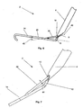
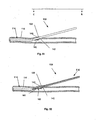
- Figure 1 is a front perspective view of an embodiment of the arteriotomy device.
- Figure 2 is a side view of the arteriotomy device of Figure 1 .
- Figure 3 is a close-up view of the arteriotomy device of Figure 1 .
- Figures 4 and 5 are close-up views of various embodiments of the anchor.
- Figure 6 is a side perspective view of an embodiment of the arteriotomy device with the introduction device deployed.
- Figure 7 is a close-up view of an embodiment of the arteriotomy device with the introduction device deployed.
- Figures 8 and 9 are side views of various embodiments of the arteriotomy device with the introduction devices deployed.
- Figure 10 is a bottom perspective view of an embodiment of the arteriotomy device.
- Figure 11 is a side view of an embodiment of the arteriotomy device with the lumenal retainer deployed.
- Figure 12 is a bottom perspective view of an embodiment of the arteriotomy device with the lumenal retainer deployed.
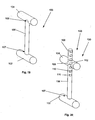
- Figure 13 is a side perspective view of an embodiment of the arteriotomy device.
- Figure 14 is a side perspective view of an embodiment of the arteriotomy device with the entry wall retainer deployed.
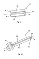
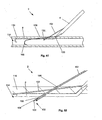
- FIGS 15 and 16 illustrate various embodiments of the tensioner.
- FIGS 17 and 18 illustrate various embodiments of the pressure clip.
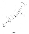
- FIGS 19 and 20 illustrate various embodiments of the toggle.
- Figure 21 illustrates a method for deploying the arteriotomy device in a cross-section of a lumen.
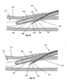
- Figures 22 and 23 illustrate methods for deploying the retainers in a cross-section of a lumen.
- Figures 24 and 25 illustrate a method for deploying the introduction device in a cross-section of a lumen.
- Figure 26 illustrates a method for deploying a guidewire in a cross-section of a lumen.
- Figures 27-30 illustrate a method for deploying the introduction device in a cross-section of a lumen.
- Figure 31 illustrates a method for deploying a guidewire in a cross-section of a lumen.
- Figure 32 illustrates a portion of an arteriotomized lumen.
- Figure 33 illustrates section A-A of Figure 28 .
- Figures 34-36 illustrate a method for deploying a tensioner in a see-through portion of lumen wall.
- Figures 37-40 illustrate methods for deploying various embodiments of the pressure clip in a cross-section of a lumen.
- Figure 41 illustrates a method of using a suture on a portion of an arteriotomized lumen.
- Figure 42 illustrates section B-B of Figure 41 with the out-of-section suture.
- Figure 43 illustrates a method of using pledgets on a portion of an arteriotomized lumen.
- Figure 44 illustrates section C-C of Figure 43 .
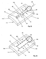
- Figure 45 illustrates an embodiment of the toggle deployment device in a first configuration.
- Figure 46 is a close-up view of Figure 45 .
- Figure 47 illustrates an embodiment of the toggle deployment device in a second configuration.
- Figure 48 is a close-up view of Figure 47 .
- Figure 49 illustrates a method of using the toggle deployment device in a cross-section of a lumen.
- Figure 50 illustrates Figure 49 with a portion of the toggle deployment device shown in section D-D.
- Figure 51 illustrates a method of using the toggle deployment device in a cross-section of a lumen.
- Figure 52 illustrates Figure 51 with a portion of the toggle deployment device shown in section E-E.
- Figures 53-55 illustrate a method of using the toggle deployment device in a cross-section of a lumen.
- Figure 56 is a close-up view of Figure 55 .
- Figure 57 illustrates an embodiment of a deployed toggle in a cross-section of a lumen.
- Figure 58 is a close-up view of Figure 59 .
- Figures 59-61 illustrate a method for deploying a toggle in a cross-section of a lumen.
- Figure 62 is a close-up view of Figure 61 .
- Figure 63 illustrates a method for deploying a toggle in a cross-section of a lumen.
- Figures 64-66 shown, in cross-section, a method for deploying the guidewire through an arteriotomy.
- Figures 67 and 68 illustrate a method for attaching guidewire to the anchor.
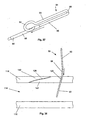
- Figures 1 through 3 illustrate a device for accessing a biological lumen, such as an arteriotomy device 2.
- the arteriotomy device 2 can have a delivery guide 4.
- the delivery guide 4 can be slidably attached to an anchor 6.
- the anchor 6 can be rigid, flexible or combinations thereof.
- the anchor 6 can be resilient, deformable or combinations thereof.
- the anchor 6 can be retractable and extendable from the delivery guide 4.
- the delivery guide 4 can have an introducer lumen 8.
- the introducer lumen 8 can have an introducer lumen exit port 10.
- the introducer lumen exit port 10 can be on the surface of the delivery guide 4.
- the anchor 6 can have an anchor angle section 12.
- the anchor 6 can have an anchor extension section 14, for example a guide eye sheath or an attachable guidewire.
- the anchor extension section 14 can extend from the anchor angle section 12.
- the anchor extension section 14 can be separate from and attached to, or integral with, the anchor angle section 12.
- the anchor angle section 12 can have an anchor angle first sub-section 16, an anchor bend 20 and an anchor angle second sub-section 18.
- the anchor angle first and/or second sub-sections 16 and/or 18 can be part of the anchor bend 20.
- the anchor bend 20 can have a sharp or gradual curve.
- the radius of curvature for the anchor bend 20 can be from about 0.1 mm (0.004 in.) to about 2.0 mm (0.079 in.).
- the anchor angle first sub-section 16 can have an anchor angle first sub-section diameter 22 from about 0.38 mm (0.015 in.) to about 1.0 mm (0.039 in.), for example about 0.71 mm (0.028 in.).
- the anchor angle second sub-section 18 can have an anchor angle second sub-section diameter 24 from about 0.38 mm (0.015 in.) to about 1.0 mm (0.039 in.), for example about 0.71 mm (0.028 in.).
- the anchor angle first sub-section 16 can have a delivery longitudinal axis 26.
- the anchor angle second sub-section 18 can have an anchor longitudinal axis 28.
- the intersection of the delivery longitudinal axis 26 and the anchor longitudinal axis 28 can be an anchoring angle 30.
- the anchoring angle 30 can be from about 20° to about 90°, more narrowly from about 30° to about 60°, for example about 45°.
- any or all elements of the arteriotomy device 2 or other devices or apparatuses described herein can be made from, for example, a single or multiple stainless steel alloys, nickel titanium alloys (e.g., Nitinol), cobalt-chrome alloys (e.g., ELGILOY® from Elgin Specialty Metals, Elgin, IL; CONICHROME® from Carpenter Metals Corp., Wyomissing, PA), molybdenum alloys (e.g., molybdenum TZM alloy, for example as disclosed in International Pub. No. WO 03/082363 A2 , published 9 October 2003, which is herein incorporated by reference in its entirety), tungsten-rhenium alloys, for example, as disclosed in International Pub.
- nickel titanium alloys e.g., Nitinol
- cobalt-chrome alloys e.g., ELGILOY® from Elgin Specialty Metals, Elgin, IL; CONICHROME® from
- polymers such as polyester (e.g., DACRON® from E. I. Du Pont de Nemours and Company, Wilmington, DE), polypropylene, polytetrafluoroethylene (PTFE), expanded PTFE (ePTFE), polyether ether ketone (PEEK), nylon, polyether-block co-polyamide polymers (e.g., PEBAX® from ATOFINA, Paris, France), aliphatic polyether polyurethanes (e.g., TECOFLEX® from Thermedics Polymer Products, Wilmington, MA), polyvinyl chloride (PVC), polyurethane, thermoplastic, fluorinated ethylene propylene (FEP), absorbable or resorbable polymers such as polyglycolic acid (PGA), polylactic acid (PLA), polydioxanone, and pseudo-polyamino tyrosine-based acids, extruded collagen, silicone, zinc, echogenic, radioactive, radiopa
- any or all elements of the arteriotomy device 2, including supplemental closure devices, such as tensioners, clips, toggles, sutures, or other devices or apparatuses described herein can be or have a matrix for cell ingrowth or used with a fabric, for example a covering (not shown) that acts as a matrix for cell ingrowth.
- the matrix and/or fabric can be, for example, polyester (e.g., DACRON® from E. I. du Pont de Nemours and Company, Wilmington, DE), polypropylene, PTFE, ePTFE, nylon, extruded collagen, silicone or combinations thereof.
- the elements of the arteriotomy device 2 and/or the fabric can be filled and/or coated with an agent delivery matrix known to one having ordinary skill in the art and/or a therapeutic and/or diagnostic agent.
- the agents within these matrices can include radioactive materials; radiopaque materials; cytogenic agents; cytotoxic agents; cytostatic agents; thrombogenic agents, for example polyurethane, cellulose acetate polymer mixed with bismuth trioxide, and ethylene vinyl alcohol; lubricious, hydrophilic materials; phosphor cholene; anti-inflammatory agents, for example non-steroidal anti-inflammatories (NSAIDs) such as cyclooxygenase-1 (COX-1) inhibitors (e.g., acetylsalicylic acid, for example ASPIRIN® from Bayer AG, Leverkusen, Germany; ibuprofen, for example ADVIL® from Wyeth, Collegeville, PA; indomethacin; mefenamic acid), COX
- Figure 4 illustrates that the anchor angle section 12 and the anchor extension section 14 can have a flexible elongated element.
- the flexible elongated element can be resilient and/or deformable.
- the flexible elongated element can have an integral, or multiple separate and fixedly attached, wound wire 32.
- the anchor angle section 12 can be in a sheath 34.
- Figure 5 illustrates that the anchor angle section 12 can have a wire coating 36, for example a lubricious coating and/or a coating made from urethane.
- FIGs 6 and 7 illustrate that the arteriotomy device 2 can have an introduction device 38.
- the introduction device 38 can be slidably attached to the introducer lumen 8.
- the introduction device 38 can have a hollow needle (as shown in Figure 6 ).
- the introduction device 38 can have a solid needle (as shown in Figure 7 ).
- the introduction device 38 can have a guidewire.
- the introduction device 38 can have an introduction longitudinal axis 40.
- the intersection of the introduction longitudinal axis 40 and the anchor longitudinal axis 28 can be an introduction angle 42.
- the introduction angle 42 can be less than or equal to about 19°, more narrowly less than or equal to about 15°, yet more narrowly from about 5° to about 10°, for example about °10.
- the introduction device 38 can have an introduction device diameter 44.
- the introduction device diameter 44 can be from about 0.25 mm (0.010 in.) to about 1.0 mm (0.039 in.), for example about 0.56 mm (0.022 in.).
- FIGs 8 and 9 illustrate that the arteriotomy device 2 can be configured so that the introduction device 38 can be deployed from the anchor 6.
- the anchor 6 can have an introduction device port 46.
- the introduction device 38 can be a hollow needle (as shown in Figure 8 ). When fully deployed, the introduction device 38 can contact the introducer lumen exit port 10.
- the introduction device 38 can be a channel between the introducer lumen 8 and the anchor 6.
- the anchor 6 can have a port (not shown) configured to communicate with the biological lumen and the introduction device 38.
- the introduction device 38 can be a solid needle (as shown in Figure 9 ).
- Figure 10 illustrates that a lumenal retainer 48 can have a first retracted configuration.
- the lumenal retainer 48 can be seated in a lumenal retainer port 50.
- the lumenal retainer port 50 can be in the anchor 6.
- the lumenal retainer 48 can be a wire, scaffold or stent for example made from a deformable or resilient material, such as a shape memory alloy - an inflatable balloon, or combinations thereof.
- Intralumenal inflatable balloons such as those inflated with saline solution or carbon dioxide, are known to those having ordinary skill in the art.
- the lumenal retainer 48 can extend into the delivery guide 4.
- Figures 11 and 12 illustrate that the lumenal retainer 48 can have a second deployed configuration.
- Figure 11 shows that the lumenal retainer 48 can be a wire or balloon.
- Figure 12 shows that the lumenal retainer 48 can be a wire.
- the lumenal retainer 48 can deploy away from the lumenal retainer port.
- the lumenal retainer 48 can have a lumenal retainer deployed diameter 52.
- the lumenal retainer deployed diameter 52 can be from about 2.54 mm (0.100 in.) to about 10.2 mm (0.400 in.), for example about 6.35 mm (0.250 in.).
- FIG. 13 illustrates that the arteriotomy device 2 can have an entry wall retainer port 54.
- the entry wall retainer port 54 can be at or near the anchor bend 20.
- the entry wall retainer port 54 can be at or near the anchor angle first sub-section 16.
- the entry wall retainer port 54 can be in fluid communication with a sensor or port (not shown) on or near the delivery guide 4 of the arteriotomy device 2.
- Figure 14 illustrates that an entry wall retainer 56 can be deployed through the entry wall retainer port 54.
- the entry wall retainer 56 can have a first retracted configuration (as shown in Figure 13 ).
- the entry wall retainer 56 can have a second deployed configuration (as shown in Figure 14 ).
- Figures 15 through 20 illustrate various supplemental closure devices.
- the supplemental closure devices can be completely or partially bioabsorbable, bioresorbable, bioadsorbable or combinations thereof.
- the supplemental closure devices can be made from homografts, heterografts or combinations thereof.
- the supplemental closure devices can be made from autografts, allografts or combinations thereof.
- FIG 15 illustrates a tensioner 58.
- the tensioner 58 can be resilient, deformable, or combinations thereof.
- the tensioner 58 can have a tensioner longitudinal axis 60.
- the tensioner 58 can have a resilient element, such as a spring, for example a tensioner head 62.
- the tensioner head 62 can have a tensioner first shoulder 64.
- the tensioner head 62 can have a tensioner second shoulder 66.
- the tensioner first and second shoulders 64 and 66 can rotatably attached to a separate or integral tensioner first leg 68 and a separate or integral tensioner second leg 70, respectively.
- the tensioner first and second legs 68 and 70 can attach to tensioner first and second feet 72 and 74, respectively.
- the tensioner legs 68 and 70 can have tensioner leg diameters 76.
- the tensioner leg diameters 76 can be from about 0.1 mm (0.005 in.) to about 0.76 mm (0.030 in.), for example about 0.38 mm (0.015 in.).
- the tensioner first and second legs 68 and 70 can have a tensioner inter-leg outer diameter 78.
- the tensioner inter-leg outer diameter 78 can be from about 1.3 mm (0.050 in.) to about 5.08 mm (0.200 in.), for example about 4.06 mm (0.160 in.).
- the tensioner shoulders 64 and/or 66 and/or the tensioner feet 72 and/or 74 can extend to a greater radius from the tensioner longitudinal axis 60 than their respective tensioner inter-leg radius.
- Figure 16 illustrates a tensioner first strut 80 that can attach to the tensioner first leg 68 and the tensioner second leg 70.
- the tensioner first leg 68 can be resilient, deformable or combinations thereof.
- a tensioner second strut 82 can attach to the tensioner first leg 68 and the tensioner second leg 70.
- the tensioner second leg 70 can be resilient and/or deformable.
- the tensioner 58 can have no tensioner head 62.
- the tensioner 58 can have more than two tensioner struts 80 and 82.
- FIG 17 illustrates a pressure clip 84.
- the pressure clip 84 can be resilient The pressure clip 84 can be deformable.
- the pressure clip 84 can have a pressure clip longitudinal axis 86.
- the pressure clip 84 can have a pressure clip head 88.
- the pressure clip head 88 can be rotatably attached to a separate or integral pressure clip first leg 90.
- the pressure clip head 88 can be rotatably attached to a separate or integral pressure clip second leg 92.
- the pressure clip can have a pressure clip first end 94 and a pressure clip second end 96.
- the pressure clip first leg 90 can terminate in the pressure clip first end 94.
- the pressure clip second leg 92 can terminate in the pressure clip second end 96.
- the pressure clip first leg 90 and/or the pressure clip second leg 92 can be biased toward the pressure clip longitudinal axis 86.
- Figure 18 illustrates the pressure clip 84 that can have a pressure clip sheath 98 slidably attached to the pressure clip second leg 92.
- the pressure clip first and/or second ends 94 and/or 96 can be pressure dissipaters, such as flat and/or curved portions, for example circular loops.
- the pressure clip first and/or second ends 94 and/or 96 can be resilient and/or deformable.
- the pressure clip first leg 90 can be rotatably attached to the pressure clip second leg 92.
- the pressure clip first leg 90 can be attached to the pressure clip second leg 92 via a rotatable, and/or deformable, and/or flexural joint in the pressure clip head 88.
- FIG 19 illustrates a toggle 100.
- the toggle 100 can have a toggle first end 102.
- the toggle 100 can have a toggle second end 104.
- the toggle first and/or second ends 102 and/or 104 can be bars, dowels, rods, beams, or combinations thereof.
- the toggle 100 can have a filament 106.
- the filament 106 can be fixedly attached at a filament first end 107 to the toggle first end 102.
- the filament 106 can be fixedly attached at a filament second end 109 to the toggle second end 104.
- the filament 106 can be resilient or deformable.
- the filament 106 can be substantially flexible.
- Figure 20 illustrates the toggle 100 that can have the filament 106 that can be slidably attached to the toggle second end 104 at a hole 108.
- the filament 106 can frictionally fit the hole 108.
- the filament 106 can have no pawls 110 (not shown in Figure 20 ).
- the filament 106 can interference fit the hole 108.
- the filament 106 can have one or more pawls 110.
- the hole 108 can have one or more notches 112.
- the notches 112 can be internal to the hole 108.
- the notches 112 and the pawls 110 can be configured to allow the toggle second end 104 to slide toward the toggle first end 102.
- the notches 112 and the pawls 110 can be configured to provide an interference fit when the toggle second end 104 is attempted to be moved away from the toggle first end 102.
- the elements of the arteriotomy device 2, including the supplemental closure devices, can be directly attached by, for example, melting, screwing, gluing, welding or use of an interference fit or pressure fit such as crimping, snapping, or combining methods thereof.
- the elements can be integrated, for example, molding, die cutting, laser cutting, electrical discharge machining (EDM) or stamping from a single piece or material. Any other methods can be used as known to those having ordinary skill in the art.
- Integrated parts can be made from pre-formed resilient materials, for example resilient alloys (e.g., Nitinol, ELGILOY®) that are preformed and biased into the post-deployment shape and then compressed into the deployment shape as known to those having ordinary skill in the art.
- resilient alloys e.g., Nitinol, ELGILOY®
- any elements of the arteriotomy device 2, including the supplemental closure devices, or the arteriotomy device 2, including the supplemental closure devices, as a whole after assembly, can be coated by dip-coating, brush-coating or spray-coating methods known to one having ordinary skill in the art. For example, these methods can be used to coat the wound wire 32 with the wire coating 36 can be spray coated, dip-coated or brushed onto the wire 32.
- the supplemental closure devices can be covered with a fabric, for example polyester (e.g., DACRON® from E. I. du Pont de Nemours and Company, Wilmington, DE), polypropylene, PTFE, ePTFE, nylon, extruded collagen, silicone or combinations thereof.
- DACRON® from E. I. du Pont de Nemours and Company, Wilmington, DE
- Figure 22 illustrates a method of deploying, as shown by arrow, the lumenal retainer 48 from the first retracted configuration to the second deployed configuration.
- the lumenal retainer 48 can be deployed by extending a wire, scaffold or stent, or by inflating a balloon.
- the anchor angle second sub-section 18 can be made substantially parallel with the lumen wall surface 118.
- the anchor angle second sub-section 18 can be made to be substantially in contact with the lumen wall surface 118.
- Figure 23 illustrates a method of deploying, as shown by arrow 122, the entry wall retainer 56 from the first retracted configuration to the second deployed configuration.
- the lumenal retainer 48 can be substantially parallel with the lumen wall surface 118.
- the lumenal retainer 48 can be substantially in contact with the lumen wall surface 118.
- a proximal force can be applied to the anchor 6, for example by being applied to the delivery guide 4.
- the anchor angle second sub-section 18 can be made substantially parallel with the lumen wall surface 118.
- the anchor angle second sub-section 18 can be made to be substantially in contact with the lumen wall surface 118.
- Figures 24 and 25 illustrate a method for deploying the introduction device 38.
- the introduction device 38 can egress from the introducer lumen 8 and the introducer lumen exit port 10.
- the introduction device 38 can be pushed, as shown by arrow, into and through the lumen wall 116.
- the introduction device 38 can form a second arteriotomy 128.
- the introduction device 38 can be pushed, as shown by arrow, adjacent to or through the anchor 6.
- the anchor 6 can be configured to have ports suitable to allow the introduction device 38 to pass through the anchor 6.
- a tip of the introduction device 38 can enter the lumen 114.
- the introduction device 38 can pass through an introduction run 132 and an introduction rise 134.
- the introduction run 132 can be the component of the length of the introduction device 38 in the lumen wall 116 that is parallel to the lumen wall 116.
- the introduction run 132 can be the component of the length parallel to the lumen wall 116 between the opening of the second arteriotomy 128 on the outside of the lumen wall 116 and the opening of the second arteriotomy 128 on the inside lumen wall surface 118.
- the introduction run 132 can be from about 0.10 cm (0.010 in.) to about 3.810 cm (1.500 in.), for example about 0.64 cm (0.25 in.).
- the introduction rise 134 can be the component of the length of the introduction device 38 in the lumen wall 116 that is perpendicular to the lumen wall 116.
- the introduction rise 134 can be the component of the length perpendicular to the lumen wall 116 between the opening of the second arteriotomy 128 on the outside of the lumen wall 116 and the opening of the second arteriotomy 128 on the inside lumen wall surface 118.
- the introduction rise 134 can be from about 0.51 mm (0.020 in.) to about 5.08 mm (0.200 in.), for example about 1.0 mm (0.040 in.).
- An introduction slope can be the ratio of the introduction rise 134 to the introduction run 132.
- the introduction slope can be from about 1 ⁇ 2 to about 1 / 40 or less, for example about 1 / 6 , also for example about 1 / 3 .
- the introduction slope can be, for examples, equal to or less than about 1 ⁇ 2 or 1 / 3 , more narrowly equal to or less than about 1 / 3 or 1 ⁇ 4 yet more narrowly equal to or less than about 1 / 5 or 1 / 6 , even still more narrowly than about equal to or less than about 1 / 10 .
- the introduction rise 134 and the introduction run 132 can be components of an introduction vector.
- the introduction run 132 can be the component of the introduction vector parallel to the lumen wall 116.
- the introduction rise 134 can be the component of the introduction vector perpendicular to the lumen wall 116.
- the introduction vector can be a vector from an outer opening 136 to an inner opening 138.
- the outer opening 136 can be a temporary or permanent opening on the outside of the lumen wall 116 formed by the introduction device 38.
- the inner opening 138 can be a temporary or permanent opening on the inside of the vessel wall.
- Figure 26 illustrates that the introduction device 38, for example a hollow needle, can act as a pathway for a lumenal tool, for example tools such as a guidewire 168, to be deployed, as shown by arrow, into the lumen 114.
- the introduction device 38 for example a solid needle, can be removed from the second arteriotomy 128 and the lumenal tool can be deployed through, for example, the introducer lumen exit port 10, and the second arteriotomy 128.
- the introduction device 38 can be the lumenal tool, for example a guidewire.
- the introduction device 38 can be further deployed and used as a lumenal tool after passing through the lumen wall 116.
- Figures 27 through 30 illustrates a method of deploying the introduction device 38 that can have a pre-formed bend.
- the arteriotomy device 2 can be configured to deploy the introduction device 38 at the introduction angle 42 from about 0° to about 5°, for example about 0°.
- the introduction device 38 can be pushed, as shown by arrow, through the lumen wall 116.
- the introduction device 38 can cleave a plane in the lumen wall 116.
- the plane can be substantially parallel with the lumen wall surface 118.
- the introduction device 38 can be adjacent to the adventitia in a blood vessel.
- the introduction device 38 can be advanced along the subintimal or submedial cleavage plane in a blood vessel.
- a subintimal angioplasty can be performed as known to one having ordinary skill in the art.
- a remote endarterectomy can be performed as known to one having ordinary skill in the art.
- Bent and straight introduction devices 38 can be swapped during use to selectively cleave the lumen wall 116. Tools, such as guidewires, can be inserted through hollow introduction devices 38 to selectively cleave the lumen wall 116.
- the introduction device 38 when the bend in the introduction device 38 moves into the lumen wall 116, the introduction device 38 can rotate, as shown by arrow, toward the biological lumen 114. As shown in Figure 30 , the bend in the introduction device 38 can continue to rotate the introduction device 38 toward the biological lumen 114. As described infra, the introduction device 38 can enter the lumen 114.
- Figure 31 illustrates that the introduction device 38 that can have the bend can act as a pathway for a lumenal tool, as described infra.
- An introducer sheath can be inserted over the guidewire 168 and/or the introduction device 38.
- the introducer sheath can be less than about 22 French (7.3 mm, 0.29 in. diameter) or less than the diameter of the lumen to which the introducer sheath is introduced.
- the introducer sheath can be, for examples, about 6 French (2.3 mm, 0.092 in. diameter), and about 8 French (2.67 mm, 0.105 in. diameter).
- the introducer sheath can be known to one having ordinary skill in the art, for example the introducer sheath described in U.S. Patent No. 5,183,464 to Dubrul, et al .
- the introducer sheath can be inserted into the second arteriotomy 128.
- the introducer sheath can expand the second arteriotomy 128 to a workable size.
- the introducer sheath can be inserted into the second arteriotomy 128 before and/or after and/or concurrently with the supplemental closure device is deployed and/or other closure method is used.
- Figures 32 and 33 illustrate an exemplary biological lumen 114 after the arteriotomy device 2 has been deployed to, and removed from, the biological lumen 114.
- the biological lumen 114 can have the first and second arteriotomies 120 and 128.
- the biological lumen 114 can have a second arteriotomy 128.
- the biological lumen 114 can have a first web 140 on one side of the arteriotomy (shown for the second arteriotomy 128), and a second web 142 on the opposite side of the arteriotomy 120 or 128.
- the natural pressure, shown by arrows, from the first and second webs 140 and 142 can self-seal the arteriotomy 120 or 128.
- One or more supplemental closure devices can be deployed to the first and/or second arteriotomies 120 and/or 128.
- the supplemental closure devices can provide a force or restraint to aid hemostasis.
- the supplemental closure devices can be permanently or temporarily deployed.
- the supplemental closure devices can biodissolve after hemostasis is achieved and/or after the relevant arteriotomy 120 or 128 is substantially or completely healed.
- the force from the supplemental closure device can be maintained from about 15 minutes to about 24 hours or more, for example about 120 minutes.
- Figure 34 illustrates a tensioner 58 in a compressed configuration. Compressive forces, shown by arrows, can compress the tensioner first and second legs 68 and 70. In a compressed configuration, the tensioner inter-leg outer diameter 78 can be from about 0.51 mm (0.020 in.) to about 2.54 mm (0.100 in.), for example about 1.5 mm (0.060 in.).
- Figures 35 and 36 illustrate a method of deploying the tensioner 58.
- the tensioner 58 can be in a compressed configuration.
- the tensioner 58 can be exposed to the compressive forces, as shown by arrows 144.
- the compressive forces can be applied by a retractable sheath, clamps, other methods known to one having ordinary skill in the art, or combinations thereof.
- a deployment force shown by arrow 146, can deploy the tensioner 58 into the arteriotomy 120 or 128.
- the compressive forces can be removed from the tensioner 58.
- the tensioner first and second leg 68 and 70 can expand, as shown by arrows.
- the tensioner 58 can force the arteriotomy 120 or 128 into a substantially or completely flat and/or closed and/or stretched configuration.
- the walls of the arteriotomy 120 or 128 can come into close contact.
- the arteriotomy 120 or 128 can have an arteriotomy width 150 and an arteriotomy height 152.
- the arteriotomy width 150 can be about half the circumference of the arteriotomy 120 or 128.
- the arteriotomy width 150 can be from about 1.0 mm (0.040 in.) to about 10.2 mm (0.400 in.), for example about 4.06 mm (0.160 in.).
- the arteriotomy height 152 can be about the tensioner leg diameter 76.
- the arteriotomy height 152 can be less than about 0.51 mm (0.020 in.), more narrowly, less than about 0.38 mm (0.015 in.).
- the arteriotomy height 152 can be from about 0.25 mm (0.010 in.) to about 1.3 mm (0.050 in.), for example about 0.38 mm (0.015 in.).
- the arteriotomy height 152 can be small enough to enable cell growth, blood clotting, acoustic sealing, heat sealing, gluing, enhanced self-sealing and combinations thereof across the arteriotomy 120 or 128.
- the tensioner first and second shoulders 64 and 66 can be wide enough to interference fit with the arteriotomy 120 or 128.
- the tensioner first and second feet 72 and 74 can be wide enough to interference fit with the arteriotomy 120 or 128.
- the tensioner first and second feet 72 and 74 can dissipate force on the lumen wall surface 118.
- the pressure clip second leg 92 can be rotated with respect to the pressure clip head 88, so that the pressure clip second leg 92 and the pressure clip head 88 are substantially aligned.
- the pressure clip second leg 92 can be deployed, as shown by the arrow, through the first arteriotomy 120.
- the pressure clip second leg 92 can be deployed through the lumen wall 116 (e.g., if there is no existing first arteriotomy 120, if the first arteriotomy 120 is not suitably located with respect to the second arteriotomy 128).
- Figure 39 illustrates contracting, and/or widening, and/or releasing and/or relaxing the pressure clip second end 96.
- the pressure clip sheath 98 can be translated, as shown by arrow, along the pressure clip second leg 92 and off of the pressure clip second end 96.
- the pressure clip second end 96 can be contracted, and/or widened, and/or released and/or relaxed after the pressure clip 84 is deployed to the arteriotomy.
- the pressure clip second leg 92 can be released or deformed so as to rotate with respect to the pressure clip head 88.
- the pressure clip head 88 can seat in the first arteriotomy 120.
- the pressure clip first and second legs 90 and 92 can apply force, as shown by arrows, to the first and second webs 140 and 142, respectively.
- Figures 41 and 42 illustrate a method of deploying a stitch 154 surrounding and/or through the arteriotomy 120 or 128.
- the stitch 154 can be tightened to apply additional pressure to the arteriotomy 120 or 128.
- the stitch 154 can have a knot 156, or other tying configuration or device, for example a pledget or clamp.
- Figures 43 and 44 illustrate a method of deploying the filament 106 adjacent to and/or through the arteriotomy 120 or 128.
- the filament 106 can be attached to a first pledget 158a by a first knot 156a or other tying configuration or device.
- the filament 106 can be attached to a second pledget 158b by a second knot 156b or other tying configuration or device.
- the first and second pledgets 158a and 158b can be other pressure diffusers known to one having ordinary skill in the art, such as the toggles 100 described infra and supra.
- FIGS 45 and 46 illustrate a toggle deployment device 159 that can be in a first retracted configuration.
- the toggle deployment device 159 can have a pressure check port 160.
- the pressure check port 160 can be in fluid communication with a sensor or port on or near the handle (not shown) of the toggle deployment device 159, such as an external lumen where blood flow can be observed, for example from flow from the end of an external tube or port and/or through a transparent or translucent window.
- the pressure check port 160 can facilitate deployment of the toggle deployment device 159 to a location where the pressure check port 160 is introduced to pressure, for example when the pressure check port 160 enters the biological lumen 114.
- the sensor or port on or near the handle of the toggle deployment device 159 will signal that the pressure check port 160 has been placed into the biological lumen 114 (e.g., by displaying a small amount of blood flow).
- the pressure check port 160 can be deployed into the biological lumen 114 and then withdrawn from the biological lumen 114 to the point where the lumen wall 116 just stops the pressure in the pressure check port 160.
- the entry wall retainer port 54 can additionally perform the function as described herein for the pressure check port 160.
- the toggle deployment device 159 can have a delivery needle port 161.
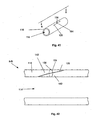
- Figures 47 and 48 illustrate the toggle deployment device 159 that can be in a second delivery configuration.
- a delivery needle 162 can be slidably attached to the toggle deployment device 159.
- the delivery needle 162 can egress from the delivery needle port 161 when the toggle deployment device 159 is in the second delivery configuration.
- Figures 49 and 50 illustrate that the toggle deployment device 159 can be deployed into the arteriotomy 120 or 128 at a location where the pressure check port 160 can be located in the biological lumen 114.
- the delivery needle port 161 can be in, or adjacent to, the lumen wall 116.
- Figures 51 and 52 illustrate that the toggle deployment device 159 can be placed in the second delivery configuration. If the delivery needle port is in, or adjacent to, the lumen wall 116 when the toggle deployment device 159 is placed in the second delivery configuration, the delivery needle 162 can enter the lumen wall 116. For example, the delivery needle 162 can enter the second web 142. The delivery needle 162 can exit the second web 142 and enter, as shown by arrows, the biological lumen 114.
- Figure 53 illustrates that a pusher 164 can be slidably attached to the delivery needle 162.
- the delivery needle 162 can have a needle tip port 166.
- the toggle 100 can be in the delivery needle 162.
- the toggle 100 can be configured in the delivery needle 162 such that the toggle first end 102 can be located on the needle tip port 166 -side of the pusher 164.
- Figure 54 illustrates that the pusher 164 can be moved, as shown by arrow, toward the needle tip port 166.
- the delivery needle 162 can be moved back relative to the pusher 164, the pusher 164 can be moved forward relative to the delivery needle 162, or combinations thereof.
- the pusher 164 can push the toggle first end 102 out of the delivery needle 162.
- the pusher 164 can push the toggle first end 102 into the biological lumen 114.
- Figures 55 and 56 illustrate that the toggle deployment device 159 can be in a first retracted configuration after deploying the toggle first end 102 into the biological lumen 114.
- the toggle second end 104 can be in the toggle deployment device 159.
- the filament 106 can extend though the delivery needle port 161.
- Figures 57 and 58 illustrate that the toggle 100 can be deployed across the lumen wall.
- the toggle deployment device 159 When the toggle deployment device 159 is removed from the arteriotomy, the toggle second end 104 can deploy on the outside of the lumen wall 116 from the delivery needle port 161.
- the toggle first end 102 can form an interference fit with the lumen wall surface 118.
- the toggle second end 104 can form an interference fit with the outside of the lumen wall 116 or the surrounding tissue, such as subcutaneous tissue.
- the toggle second end 104 can be slidably translated along the filament 106 toward the lumen wall 116, for example for the toggle 100 illustrated in Figure 20 .
- the length of the filament 106 on the opposite side of toggle second end 104 from the toggle first end 102 can be cut, snapped, torn or otherwise removed.
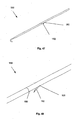
- Figures 59 through 63 illustrate a method for deploying the toggle 100.
- the delivery needle 162 can egress, as shown by arrow, from a toggle deployment delivery port 163.
- the toggle deployment delivery port 163 can be in the delivery guide 4.
- the delivery needle 162 can be advanced toward the lumen 114.
- Figure 60 illustrates that the delivery needle 162 can be deployed through the lumen wall.
- the delivery needle 162 When the delivery needle 162 is deployed through the lumen wall 116, the delivery needle can intersect, or pass adjacent to, the second arteriotomy.
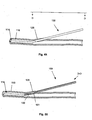
- Figures 61 and 62 illustrate that the pusher 164 can be advanced, as shown by arrow, through the delivery needle 162.
- the toggle first end 102 can egress from the needle tip port 166.
- the toggle first end 102 can deploy into the lumen 114.
- Figure 63 illustrates that the delivery needle 162 can be retracted into the delivery guide 4 and/or the filament 106 can be pulled taught, both shown by arrow.
- the toggle first end 102 can form an interference fit with the lumen wall surface 118.
- the toggle second end 104 (not shown in Figure 63 ) can be slidably translated on the filament 106 down to, and form an interference fit with, the outside of the lumen wall 116.
- the length of the filament 106 on the opposite side of toggle second end 104 from the toggle first end 102 can be cut, snapped, torn or otherwise removed.
- Figure 64 illustrates an introducer needle 165 that can have an end inserted, as shown by arrow, through the lumen wall 116 and into the lumen 114, for example by using the Seldinger technique.
- the introducer needle 165 can be hollow and/or have a longitudinal channel.
- Figure 65 illustrates that the guidewire 168 can be deployed, shown by arrows, through the hollow and/or longitudinal channel of the introducer needle 165.
- Figure 66 illustrates that the introducer needle 165 can be removed, as shown by arrow, from the lumen wall 116.
- the guidewire 168 can remain substantially in place. After the introducer needle 165 is removed, a portion of the guidewire 168 can be outside the lumen 114 and another portion of the guidewire 168 can be inside the lumen 114.
- Figure 67 illustrates a method of fixedly or slidably attaching the guidewire 168 to the anchor 6.
- a guidewire proximal end 170 can be placed in proximity to an anchor distal end 172. The guidewire proximal end 170 can then be attached, as shown by arrows, to the anchor distal end 172. The guidewire proximal end 170 can be attached to the anchor distal end 172 while some or all of the guidewire 168 is in the lumen 114.
- the guidewire proximal end 170 can be configured to snap-fit, interference fit, slidably attach or combinations thereof, to the anchor 6. When the guidewire 168 is attached to the anchor 6, the guidewire 168 can act as the anchor extension section 14 and/or the lumenal tool.
- Figure 68 illustrates the guidewire 168 attached to the anchor 6.
Abstract
Description
- The present invention relates to the field of accessing a biological lumen and closing the access port thereby created.
- A number of diagnostic and interventional vascular procedures are now performed translumenally, where a catheter is introduced to the vascular system at a convenient access location - such as the femoral, brachial, or subclavian arteries - and guided through the vascular system to a target location to perform therapy or diagnosis. When vascular access is no longer required, the catheter and other vascular access devices must be removed from the vascular entrance and bleeding at the puncture site must be stopped.
- One common approach for providing hemostasis is to apply external force near and upstream from the puncture site, typically by manual compression. This method is time-consuming, frequently requiring one-half hour or more of compression before hemostasis. This procedure is uncomfortable for the patient and frequently requires administering analgesics. Excessive pressure can also present the risk of total occlusion of the blood vessel, resulting in ischemia and/or thrombosis.
- After hemostasis is achieved by manual compression, the patient is required to remain recumbent for six to eighteen hours under observation to assure continued hemostasis. During this time bleeding from the vascular access wound can restart, potentially resulting in major complications. These complications may require blood transfusion and/or surgical intervention.
- Bioabsorbable fasteners have also been used to stop bleeding. Generally, these approaches rely on the placement of a thrombogenic and bioabsorbable material, such as collagen, at the superficial arterial wall over the puncture site. This method generally presents difficulty locating the interface of the overlying tissue and the adventitial surface of the blood vessel. Implanting the fastener too far from the desired location can result in failure to provide hemostasis. If, however, the fastener intrudes into the vascular lumen, thrombus can form on the fastener. Thrombus can embolize downstream and/or block normal blood flow at the thrombus site. Implanted fasteners can also cause infection and auto-immune reactions/rejections of the implant.
- Suturing methods are also used to provide hemostasis after vascular access. The suture-applying device is introduced through the tissue tract with a distal end of the device located at the vascular puncture. Needles in the device draw suture through the blood vessel wall on opposite sides of the punctures, and the suture is secured directly over the adventitial surface of the blood vessel wall to close the vascular access wound.
- To be successful, suturing methods need to be performed with a precise control. The needles need to be properly directed through the blood vessel wall so that the suture is well anchored in tissue to provide for tight closure. Suturing methods also require additional steps for the surgeon.
- Due to the deficiencies of the above methods and devices, a need exists for a more reliable vascular closure method and device. There also exists a need for a vascular closure device and method that does not implant a foreign substance and is self-sealing. There also exists a need for a vascular closure device and method requiring no or few extra steps to close the vascular site.
- A device for accessing a biological lumen is disclosed. The biological lumen has a lumen wall having a longitudinal lumen wall axis. The device has an elongated member that has a longitudinal member axis. The member is configured to access the lumen at a first angle. The first angle is defined by the longitudinal lumen wall axis and the longitudinal member axis. The first angle is less than about 19 degrees.
- The first angle can be less than about 15 degrees. The first angle can be less than about 10 degrees. The device can also have an anchor. The anchor can be configured to hold the elongated member at a fixed angle with respect to the longitudinal lumen wall axis.
- The device can also have a retainer. The retainer can be configured to hold the elongated member at a fixed angle with respect to the longitudinal lumen axis.
- Another device for accessing a biological lumen is disclosed. The biological lumen has a lumen wall and a longitudinal lumen wall axis. The device has a first elongated member and a second elongated member. The first elongated member has a first elongated member axis. The second elongated member has a second elongated member axis. The second elongated member is configured so that the second elongated member axis is parallel to the longitudinal lumen wall axis.
- The second elongated member can have a retainer. The retainer can have an inflatable member. The retainer can have a resilient member. The second elongated member can extend substantially adjacent to the lumen wall.
- Also disclosed is a device for closing an opening on a biological lumen wall. The device has a longitudinal axis, a first force-applying member, a second force-applying member, and a resilient member. The resilient member provides to the first and the second force-applying members a force that is radially outward with respect to the longitudinal axis.
- A method of accessing a blood vessel through a blood vessel wall is also disclosed. The blood vessel wall has a longitudinal wall axis. The method includes entering the vessel at an angle of less than about 19 degrees with respect to the longitudinal wall axis. The method also includes inserting a lumenal tool into the vessel.
- Also disclosed is a method for accessing a biological lumen. The biological lumen has a lumen wall and a longitudinal lumen wall axis. The method includes inserting in the biological lumen a second elongated member. The second elongated member has a second elongated member axis. The method also includes aligning the second elongated member so that the second elongated member axis is substantially parallel to the longitudinal lumen wall axis. Further, the method includes inserting in the biological lumen a first elongated member comprising a first elongated member axis.
- Additionally disclosed is a method of closing a vascular opening. The vascular opening has an inside surface and a longitudinal axis. The method includes inserting a device in the opening and applying a force to the inside surface. The force is directed in at least one radially outward direction from the longitudinal axis.
- The method can include maintaining the force. The applying a force can include the device applying at least a part of the force. The applying of a force can include the device applying all of the force.
- Also disclosed is a method for accessing and closing a blood vessel having a vessel wall. The vessel wall can have an inside surface and an outside surface. The method includes forming an arteriotomy and deploying a closure augmentation device in the arteriotomy. The closure augmentation device produces pressure on the inside surface and the outside surface.
-
Figure 1 is a front perspective view of an embodiment of the arteriotomy device. -
Figure 2 is a side view of the arteriotomy device ofFigure 1 . -
Figure 3 is a close-up view of the arteriotomy device ofFigure 1 . -
Figures 4 and 5 are close-up views of various embodiments of the anchor. -
Figure 6 is a side perspective view of an embodiment of the arteriotomy device with the introduction device deployed. -
Figure 7 is a close-up view of an embodiment of the arteriotomy device with the introduction device deployed. -
Figures 8 and 9 are side views of various embodiments of the arteriotomy device with the introduction devices deployed. -
Figure 10 is a bottom perspective view of an embodiment of the arteriotomy device. -
Figure 11 is a side view of an embodiment of the arteriotomy device with the lumenal retainer deployed. -
Figure 12 is a bottom perspective view of an embodiment of the arteriotomy device with the lumenal retainer deployed. -
Figure 13 is a side perspective view of an embodiment of the arteriotomy device. -
Figure 14 is a side perspective view of an embodiment of the arteriotomy device with the entry wall retainer deployed. -
Figures 15 and 16 illustrate various embodiments of the tensioner. -
Figures 17 and 18 illustrate various embodiments of the pressure clip. -
Figures 19 and 20 illustrate various embodiments of the toggle. -
Figure 21 illustrates a method for deploying the arteriotomy device in a cross-section of a lumen. -
Figures 22 and23 illustrate methods for deploying the retainers in a cross-section of a lumen. -
Figures 24 and25 illustrate a method for deploying the introduction device in a cross-section of a lumen. -
Figure 26 illustrates a method for deploying a guidewire in a cross-section of a lumen. -
Figures 27-30 illustrate a method for deploying the introduction device in a cross-section of a lumen. -
Figure 31 illustrates a method for deploying a guidewire in a cross-section of a lumen. -
Figure 32 illustrates a portion of an arteriotomized lumen. -
Figure 33 illustrates section A-A ofFigure 28 . -
Figures 34-36 illustrate a method for deploying a tensioner in a see-through portion of lumen wall. -
Figures 37-40 illustrate methods for deploying various embodiments of the pressure clip in a cross-section of a lumen. -
Figure 41 illustrates a method of using a suture on a portion of an arteriotomized lumen. -
Figure 42 illustrates section B-B ofFigure 41 with the out-of-section suture. -
Figure 43 illustrates a method of using pledgets on a portion of an arteriotomized lumen. -
Figure 44 illustrates section C-C ofFigure 43 . -
Figure 45 illustrates an embodiment of the toggle deployment device in a first configuration. -
Figure 46 is a close-up view ofFigure 45 . -
Figure 47 illustrates an embodiment of the toggle deployment device in a second configuration. -
Figure 48 is a close-up view ofFigure 47 . -
Figure 49 illustrates a method of using the toggle deployment device in a cross-section of a lumen. -
Figure 50 illustratesFigure 49 with a portion of the toggle deployment device shown in section D-D. -
Figure 51 illustrates a method of using the toggle deployment device in a cross-section of a lumen. -
Figure 52 illustratesFigure 51 with a portion of the toggle deployment device shown in section E-E. -
Figures 53-55 illustrate a method of using the toggle deployment device in a cross-section of a lumen. -
Figure 56 is a close-up view ofFigure 55 . -
Figure 57 illustrates an embodiment of a deployed toggle in a cross-section of a lumen. -
Figure 58 is a close-up view ofFigure 59 . -
Figures 59-61 illustrate a method for deploying a toggle in a cross-section of a lumen. -
Figure 62 is a close-up view ofFigure 61 . -
Figure 63 illustrates a method for deploying a toggle in a cross-section of a lumen. -
Figures 64-66 shown, in cross-section, a method for deploying the guidewire through an arteriotomy. -
Figures 67 and68 illustrate a method for attaching guidewire to the anchor. -
Figures 1 through 3 illustrate a device for accessing a biological lumen, such as anarteriotomy device 2. Thearteriotomy device 2 can have adelivery guide 4. Thedelivery guide 4 can be slidably attached to ananchor 6. Theanchor 6 can be rigid, flexible or combinations thereof. Theanchor 6 can be resilient, deformable or combinations thereof. Theanchor 6 can be retractable and extendable from thedelivery guide 4. Thedelivery guide 4 can have anintroducer lumen 8. Theintroducer lumen 8 can have an introducerlumen exit port 10. The introducerlumen exit port 10 can be on the surface of thedelivery guide 4. - The
anchor 6 can have ananchor angle section 12. Theanchor 6 can have ananchor extension section 14, for example a guide eye sheath or an attachable guidewire. Theanchor extension section 14 can extend from theanchor angle section 12. Theanchor extension section 14 can be separate from and attached to, or integral with, theanchor angle section 12. - The
anchor angle section 12 can have an anchor anglefirst sub-section 16, ananchor bend 20 and an anchor anglesecond sub-section 18. The anchor angle first and/orsecond sub-sections 16 and/or 18 can be part of theanchor bend 20. Theanchor bend 20 can have a sharp or gradual curve. The radius of curvature for theanchor bend 20 can be from about 0.1 mm (0.004 in.) to about 2.0 mm (0.079 in.). - The anchor angle
first sub-section 16 can have an anchor anglefirst sub-section diameter 22 from about 0.38 mm (0.015 in.) to about 1.0 mm (0.039 in.), for example about 0.71 mm (0.028 in.). The anchor anglesecond sub-section 18 can have an anchor anglesecond sub-section diameter 24 from about 0.38 mm (0.015 in.) to about 1.0 mm (0.039 in.), for example about 0.71 mm (0.028 in.). - The anchor angle
first sub-section 16 can have a deliverylongitudinal axis 26. The anchor anglesecond sub-section 18 can have an anchorlongitudinal axis 28. The intersection of the deliverylongitudinal axis 26 and the anchorlongitudinal axis 28 can be an anchoringangle 30. The anchoringangle 30 can be from about 20° to about 90°, more narrowly from about 30° to about 60°, for example about 45°. - Any or all elements of the
arteriotomy device 2 or other devices or apparatuses described herein can be made from, for example, a single or multiple stainless steel alloys, nickel titanium alloys (e.g., Nitinol), cobalt-chrome alloys (e.g., ELGILOY® from Elgin Specialty Metals, Elgin, IL; CONICHROME® from Carpenter Metals Corp., Wyomissing, PA), molybdenum alloys (e.g., molybdenum TZM alloy, for example as disclosed in International Pub. No.WO 03/082363 A2 WO 03/082363 - Any or all elements of the
arteriotomy device 2, including supplemental closure devices, such as tensioners, clips, toggles, sutures, or other devices or apparatuses described herein can be or have a matrix for cell ingrowth or used with a fabric, for example a covering (not shown) that acts as a matrix for cell ingrowth. The matrix and/or fabric can be, for example, polyester (e.g., DACRON® from E. I. du Pont de Nemours and Company, Wilmington, DE), polypropylene, PTFE, ePTFE, nylon, extruded collagen, silicone or combinations thereof. - The elements of the
arteriotomy device 2 and/or the fabric can be filled and/or coated with an agent delivery matrix known to one having ordinary skill in the art and/or a therapeutic and/or diagnostic agent. The agents within these matrices can include radioactive materials; radiopaque materials; cytogenic agents; cytotoxic agents; cytostatic agents; thrombogenic agents, for example polyurethane, cellulose acetate polymer mixed with bismuth trioxide, and ethylene vinyl alcohol; lubricious, hydrophilic materials; phosphor cholene; anti-inflammatory agents, for example non-steroidal anti-inflammatories (NSAIDs) such as cyclooxygenase-1 (COX-1) inhibitors (e.g., acetylsalicylic acid, for example ASPIRIN® from Bayer AG, Leverkusen, Germany; ibuprofen, for example ADVIL® from Wyeth, Collegeville, PA; indomethacin; mefenamic acid), COX-2 inhibitors (e.g., VIOXX® from Merck & Co., Inc., Whitehouse Station, NJ; CELEBREX® from Pharmacia Corp., Peapack, NJ; COX-1 inhibitors); immunosuppressive agents, for example Sirolimus (RAPAMUNE®, from Wyeth, , Collegeville, PA), or matrix metalloproteinase (MMP) inhibitors (e.g., tetracycline and tetracycline derivatives) that act early within the pathways of an inflammatory response. Examples of other agents are provided in Walton et al, Inhibition of Prostoglandin E2 Synthesis in Abdominal Aortic Aneurysms, Circulation, July 6, 1999, 48-54; Tambiah et al, Provocation of Experimental Aortic Inflammation Mediators and Chlamydia Pneumoniae, Brit. J. Surgery 88 (7), 935-940; Franklin et al, Uptake of Tetracycline by Aortic Aneurysm Wall and Its Effect on Inflammation and Proteolysis, Brit. J. Surgery 86 (6), 771-775; Xu et al, Sp1 Increases Expression of Cyclooxygenase-2 in Hypoxic Vascular Endothelium, J. Biological Chemistry 275 (32) 24583-24589; and Pyo et al, Targeted Gene Disruption of Matrix Metalloproteinase-9 (Gelatinase B) Suppresses Development of Experimental Abdominal Aortic Aneurysms, J. Clinical Investigation 105 (11), 1641-1649 which are all incorporated by reference in their entireties. -
Figure 4 illustrates that theanchor angle section 12 and theanchor extension section 14 can have a flexible elongated element. The flexible elongated element can be resilient and/or deformable. The flexible elongated element can have an integral, or multiple separate and fixedly attached,wound wire 32. Theanchor angle section 12 can be in asheath 34.Figure 5 illustrates that theanchor angle section 12 can have awire coating 36, for example a lubricious coating and/or a coating made from urethane. -
Figures 6 and 7 illustrate that thearteriotomy device 2 can have anintroduction device 38. Theintroduction device 38 can be slidably attached to theintroducer lumen 8. Theintroduction device 38 can have a hollow needle (as shown inFigure 6 ). Theintroduction device 38 can have a solid needle (as shown inFigure 7 ). Theintroduction device 38 can have a guidewire. - The
introduction device 38 can have an introductionlongitudinal axis 40. The intersection of the introductionlongitudinal axis 40 and the anchorlongitudinal axis 28 can be anintroduction angle 42. Theintroduction angle 42 can be less than or equal to about 19°, more narrowly less than or equal to about 15°, yet more narrowly from about 5° to about 10°, for example about °10. - The
introduction device 38 can have anintroduction device diameter 44. Theintroduction device diameter 44 can be from about 0.25 mm (0.010 in.) to about 1.0 mm (0.039 in.), for example about 0.56 mm (0.022 in.). -
Figures 8 and 9 illustrate that thearteriotomy device 2 can be configured so that theintroduction device 38 can be deployed from theanchor 6. Theanchor 6 can have anintroduction device port 46. Theintroduction device 38 can be a hollow needle (as shown inFigure 8 ). When fully deployed, theintroduction device 38 can contact the introducerlumen exit port 10. Theintroduction device 38 can be a channel between theintroducer lumen 8 and theanchor 6. Theanchor 6 can have a port (not shown) configured to communicate with the biological lumen and theintroduction device 38. Theintroduction device 38 can be a solid needle (as shown inFigure 9 ). -
Figure 10 illustrates that alumenal retainer 48 can have a first retracted configuration. Thelumenal retainer 48 can be seated in alumenal retainer port 50. Thelumenal retainer port 50 can be in theanchor 6. Thelumenal retainer 48 can be a wire, scaffold or stent for example made from a deformable or resilient material, such as a shape memory alloy - an inflatable balloon, or combinations thereof. Intralumenal inflatable balloons, such as those inflated with saline solution or carbon dioxide, are known to those having ordinary skill in the art. Thelumenal retainer 48 can extend into thedelivery guide 4. -
Figures 11 and 12 illustrate that thelumenal retainer 48 can have a second deployed configuration.Figure 11 shows that thelumenal retainer 48 can be a wire or balloon.Figure 12 shows that thelumenal retainer 48 can be a wire. In the deployed configuration, thelumenal retainer 48 can deploy away from the lumenal retainer port. Thelumenal retainer 48 can have a lumenal retainer deployeddiameter 52. The lumenal retainer deployeddiameter 52 can be from about 2.54 mm (0.100 in.) to about 10.2 mm (0.400 in.), for example about 6.35 mm (0.250 in.). -
Figure 13 illustrates that thearteriotomy device 2 can have an entrywall retainer port 54. The entrywall retainer port 54 can be at or near theanchor bend 20. The entrywall retainer port 54 can be at or near the anchor anglefirst sub-section 16. The entrywall retainer port 54 can be in fluid communication with a sensor or port (not shown) on or near thedelivery guide 4 of thearteriotomy device 2. -
Figure 14 illustrates that anentry wall retainer 56 can be deployed through the entrywall retainer port 54. Theentry wall retainer 56 can have a first retracted configuration (as shown inFigure 13 ). Theentry wall retainer 56 can have a second deployed configuration (as shown inFigure 14 ). -
Figures 15 through 20 illustrate various supplemental closure devices. The supplemental closure devices can be completely or partially bioabsorbable, bioresorbable, bioadsorbable or combinations thereof. The supplemental closure devices can be made from homografts, heterografts or combinations thereof. The supplemental closure devices can be made from autografts, allografts or combinations thereof. -
Figure 15 illustrates atensioner 58. Thetensioner 58 can be resilient, deformable, or combinations thereof. Thetensioner 58 can have a tensionerlongitudinal axis 60. Thetensioner 58 can have a resilient element, such as a spring, for example atensioner head 62. Thetensioner head 62 can have a tensionerfirst shoulder 64. Thetensioner head 62 can have a tensionersecond shoulder 66. The tensioner first andsecond shoulders first leg 68 and a separate or integral tensionersecond leg 70, respectively. The tensioner first andsecond legs second feet - The
tensioner legs tensioner leg diameters 76. Thetensioner leg diameters 76 can be from about 0.1 mm (0.005 in.) to about 0.76 mm (0.030 in.), for example about 0.38 mm (0.015 in.). The tensioner first andsecond legs outer diameter 78. The tensioner inter-legouter diameter 78 can be from about 1.3 mm (0.050 in.) to about 5.08 mm (0.200 in.), for example about 4.06 mm (0.160 in.). The tensioner shoulders 64 and/or 66 and/or thetensioner feet 72 and/or 74 can extend to a greater radius from the tensionerlongitudinal axis 60 than their respective tensioner inter-leg radius. -
Figure 16 illustrates a tensionerfirst strut 80 that can attach to the tensionerfirst leg 68 and the tensionersecond leg 70. The tensionerfirst leg 68 can be resilient, deformable or combinations thereof. A tensionersecond strut 82 can attach to the tensionerfirst leg 68 and the tensionersecond leg 70. The tensionersecond leg 70 can be resilient and/or deformable. Thetensioner 58 can have notensioner head 62. Thetensioner 58 can have more than two tensioner struts 80 and 82. -
Figure 17 illustrates apressure clip 84. Thepressure clip 84 can be resilient Thepressure clip 84 can be deformable. Thepressure clip 84 can have a pressure cliplongitudinal axis 86. Thepressure clip 84 can have apressure clip head 88. Thepressure clip head 88 can be rotatably attached to a separate or integral pressure clipfirst leg 90. Thepressure clip head 88 can be rotatably attached to a separate or integral pressure clipsecond leg 92. The pressure clip can have a pressure clipfirst end 94 and a pressure clipsecond end 96. The pressure clipfirst leg 90 can terminate in the pressure clipfirst end 94. The pressure clipsecond leg 92 can terminate in the pressure clipsecond end 96. The pressure clipfirst leg 90 and/or the pressure clipsecond leg 92 can be biased toward the pressure cliplongitudinal axis 86. -
Figure 18 illustrates thepressure clip 84 that can have apressure clip sheath 98 slidably attached to the pressure clipsecond leg 92. The pressure clip first and/or second ends 94 and/or 96 can be pressure dissipaters, such as flat and/or curved portions, for example circular loops. The pressure clip first and/or second ends 94 and/or 96 can be resilient and/or deformable. The pressure clipfirst leg 90 can be rotatably attached to the pressure clipsecond leg 92. The pressure clipfirst leg 90 can be attached to the pressure clipsecond leg 92 via a rotatable, and/or deformable, and/or flexural joint in thepressure clip head 88. -
Figure 19 illustrates atoggle 100. Thetoggle 100 can have a togglefirst end 102. Thetoggle 100 can have a togglesecond end 104. The toggle first and/or second ends 102 and/or 104 can be bars, dowels, rods, beams, or combinations thereof. Thetoggle 100 can have afilament 106. Thefilament 106 can be fixedly attached at a filamentfirst end 107 to the togglefirst end 102. Thefilament 106 can be fixedly attached at a filamentsecond end 109 to the togglesecond end 104. Thefilament 106 can be resilient or deformable. Thefilament 106 can be substantially flexible. -
Figure 20 illustrates thetoggle 100 that can have thefilament 106 that can be slidably attached to the togglesecond end 104 at ahole 108. Thefilament 106 can frictionally fit thehole 108. Thefilament 106 can have no pawls 110 (not shown inFigure 20 ). Thefilament 106 can interference fit thehole 108. Thefilament 106 can have one or more pawls 110. Thehole 108 can have one ormore notches 112. Thenotches 112 can be internal to thehole 108. Thenotches 112 and thepawls 110 can be configured to allow the togglesecond end 104 to slide toward the togglefirst end 102. Thenotches 112 and thepawls 110 can be configured to provide an interference fit when the togglesecond end 104 is attempted to be moved away from the togglefirst end 102. - The elements of the
arteriotomy device 2, including the supplemental closure devices, can be directly attached by, for example, melting, screwing, gluing, welding or use of an interference fit or pressure fit such as crimping, snapping, or combining methods thereof. The elements can be integrated, for example, molding, die cutting, laser cutting, electrical discharge machining (EDM) or stamping from a single piece or material. Any other methods can be used as known to those having ordinary skill in the art. - Integrated parts can be made from pre-formed resilient materials, for example resilient alloys (e.g., Nitinol, ELGILOY®) that are preformed and biased into the post-deployment shape and then compressed into the deployment shape as known to those having ordinary skill in the art.
- Any elements of the
arteriotomy device 2, including the supplemental closure devices, or thearteriotomy device 2, including the supplemental closure devices, as a whole after assembly, can be coated by dip-coating, brush-coating or spray-coating methods known to one having ordinary skill in the art. For example, these methods can be used to coat thewound wire 32 with thewire coating 36 can be spray coated, dip-coated or brushed onto thewire 32. - One example of a method used to coat a medical device for vascular use is provided in
U.S. Patent No. 6,358,556 by Ding et al. and hereby incorporated by reference in its entirety. Time release coating methods known to one having ordinary skill in the art can also be used to delay the release of an agent in the coating, for example the coatings on the supplemental closure devices. - The supplemental closure devices can be covered with a fabric, for example polyester (e.g., DACRON® from E. I. du Pont de Nemours and Company, Wilmington, DE), polypropylene, PTFE, ePTFE, nylon, extruded collagen, silicone or combinations thereof. Methods of covering an implantable device with fabric are known to those having ordinary skill in the art.
-
Figure 21 illustrates a method of inserting theanchor 6 into abiological lumen 114, for example a blood vessel, such as a femoral artery. Thebiological lumen 114 can have alumen wall 116 and alumen wall surface 118. Theanchor 6 can be inserted into thebiological lumen 114 using a Seldinger technique, modified Seldinger technique, or other method known to one having ordinary skill in the art. Theanchor 6 can create afirst arteriotomy 120. Theanchor 6 can be inserted into thelumen 114 so that the anchor anglesecond sub-section 18 can be substantially parallel with thelumen wall surface 118. Theanchor 6 can be inserted into thelumen 114 so that the anchor anglesecond sub-section 18 can be substantially in contact with thelumen wall surface 118. -
Figure 22 illustrates a method of deploying, as shown by arrow, thelumenal retainer 48 from the first retracted configuration to the second deployed configuration. Thelumenal retainer 48 can be deployed by extending a wire, scaffold or stent, or by inflating a balloon. When thelumenal retainer 48 is deployed, the anchor anglesecond sub-section 18 can be made substantially parallel with thelumen wall surface 118. When thelumenal retainer 48 is deployed, the anchor anglesecond sub-section 18 can be made to be substantially in contact with thelumen wall surface 118. -
Figure 23 illustrates a method of deploying, as shown byarrow 122, theentry wall retainer 56 from the first retracted configuration to the second deployed configuration. When the lumenal retainer is in the second deployed configuration, thelumenal retainer 48 can be substantially parallel with thelumen wall surface 118. When the lumenal retainer is in the second deployed configuration, thelumenal retainer 48 can be substantially in contact with thelumen wall surface 118. - A proximal force, as shown by
arrow 124, can be applied to theanchor 6, for example by being applied to thedelivery guide 4. When the proximal force is applied, the anchor anglesecond sub-section 18 can be made substantially parallel with thelumen wall surface 118. When the proximal force is applied, the anchor anglesecond sub-section 18 can be made to be substantially in contact with thelumen wall surface 118. -
Figures 24 and25 illustrate a method for deploying theintroduction device 38. Theintroduction device 38 can egress from theintroducer lumen 8 and the introducerlumen exit port 10. As shown inFigure 24 , theintroduction device 38 can be pushed, as shown by arrow, into and through thelumen wall 116. Theintroduction device 38 can form asecond arteriotomy 128. As shown inFigure 25 , theintroduction device 38 can be pushed, as shown by arrow, adjacent to or through theanchor 6. Theanchor 6 can be configured to have ports suitable to allow theintroduction device 38 to pass through theanchor 6. A tip of theintroduction device 38 can enter thelumen 114. - The
introduction device 38 can pass through anintroduction run 132 and anintroduction rise 134. Theintroduction run 132 can be the component of the length of theintroduction device 38 in thelumen wall 116 that is parallel to thelumen wall 116. Theintroduction run 132 can be the component of the length parallel to thelumen wall 116 between the opening of thesecond arteriotomy 128 on the outside of thelumen wall 116 and the opening of thesecond arteriotomy 128 on the insidelumen wall surface 118. Theintroduction run 132 can be from about 0.10 cm (0.010 in.) to about 3.810 cm (1.500 in.), for example about 0.64 cm (0.25 in.). - The introduction rise 134 can be the component of the length of the
introduction device 38 in thelumen wall 116 that is perpendicular to thelumen wall 116. The introduction rise 134 can be the component of the length perpendicular to thelumen wall 116 between the opening of thesecond arteriotomy 128 on the outside of thelumen wall 116 and the opening of thesecond arteriotomy 128 on the insidelumen wall surface 118. The introduction rise 134 can be from about 0.51 mm (0.020 in.) to about 5.08 mm (0.200 in.), for example about 1.0 mm (0.040 in.). An introduction slope can be the ratio of the introduction rise 134 to theintroduction run 132. The introduction slope can be from about ½ to about 1/40 or less, for example about 1/6, also for example about 1/3. The introduction slope can be, for examples, equal to or less than about ½ or 1/3, more narrowly equal to or less than about 1/3 or ¼ yet more narrowly equal to or less than about 1/5 or 1/6, even still more narrowly than about equal to or less than about 1/10. - The introduction rise 134 and the
introduction run 132 can be components of an introduction vector. Theintroduction run 132 can be the component of the introduction vector parallel to thelumen wall 116. The introduction rise 134 can be the component of the introduction vector perpendicular to thelumen wall 116. The introduction vector can be a vector from anouter opening 136 to aninner opening 138. Theouter opening 136 can be a temporary or permanent opening on the outside of thelumen wall 116 formed by theintroduction device 38. Theinner opening 138 can be a temporary or permanent opening on the inside of the vessel wall. -
Figure 26 illustrates that theintroduction device 38, for example a hollow needle, can act as a pathway for a lumenal tool, for example tools such as aguidewire 168, to be deployed, as shown by arrow, into thelumen 114. Theintroduction device 38, for example a solid needle, can be removed from thesecond arteriotomy 128 and the lumenal tool can be deployed through, for example, the introducerlumen exit port 10, and thesecond arteriotomy 128. Theintroduction device 38 can be the lumenal tool, for example a guidewire. Theintroduction device 38 can be further deployed and used as a lumenal tool after passing through thelumen wall 116. -
Figures 27 through 30 illustrates a method of deploying theintroduction device 38 that can have a pre-formed bend. As shown inFigure 27 , thearteriotomy device 2 can be configured to deploy theintroduction device 38 at theintroduction angle 42 from about 0° to about 5°, for example about 0°. - As shown in
Figure 28 , theintroduction device 38 can be pushed, as shown by arrow, through thelumen wall 116. Theintroduction device 38 can cleave a plane in thelumen wall 116. The plane can be substantially parallel with thelumen wall surface 118. Theintroduction device 38 can be adjacent to the adventitia in a blood vessel. Theintroduction device 38 can be advanced along the subintimal or submedial cleavage plane in a blood vessel. Once the lumen wall has been cleaved, a subintimal angioplasty can be performed as known to one having ordinary skill in the art. Once the lumen wall has been cleaved, a remote endarterectomy can be performed as known to one having ordinary skill in the art. Bent andstraight introduction devices 38 can be swapped during use to selectively cleave thelumen wall 116. Tools, such as guidewires, can be inserted throughhollow introduction devices 38 to selectively cleave thelumen wall 116. - As shown in
Figure 29 , when the bend in theintroduction device 38 moves into thelumen wall 116, theintroduction device 38 can rotate, as shown by arrow, toward thebiological lumen 114. As shown inFigure 30 , the bend in theintroduction device 38 can continue to rotate theintroduction device 38 toward thebiological lumen 114. As described infra, theintroduction device 38 can enter thelumen 114.Figure 31 illustrates that theintroduction device 38 that can have the bend can act as a pathway for a lumenal tool, as described infra. - An introducer sheath can be inserted over the
guidewire 168 and/or theintroduction device 38. The introducer sheath can be less than about 22 French (7.3 mm, 0.29 in. diameter) or less than the diameter of the lumen to which the introducer sheath is introduced. The introducer sheath can be, for examples, about 6 French (2.3 mm, 0.092 in. diameter), and about 8 French (2.67 mm, 0.105 in. diameter). The introducer sheath can be known to one having ordinary skill in the art, for example the introducer sheath described inU.S. Patent No. 5,183,464 to Dubrul, et al . - The introducer sheath can be inserted into the
second arteriotomy 128. The introducer sheath can expand thesecond arteriotomy 128 to a workable size. The introducer sheath can be inserted into thesecond arteriotomy 128 before and/or after and/or concurrently with the supplemental closure device is deployed and/or other closure method is used. -
Figures 32 and 33 illustrate an exemplarybiological lumen 114 after thearteriotomy device 2 has been deployed to, and removed from, thebiological lumen 114. Thebiological lumen 114 can have the first andsecond arteriotomies biological lumen 114 can have asecond arteriotomy 128. Thebiological lumen 114 can have afirst web 140 on one side of the arteriotomy (shown for the second arteriotomy 128), and asecond web 142 on the opposite side of thearteriotomy second webs arteriotomy - One or more supplemental closure devices can be deployed to the first and/or
second arteriotomies 120 and/or 128. The supplemental closure devices can provide a force or restraint to aid hemostasis. The supplemental closure devices can be permanently or temporarily deployed. The supplemental closure devices can biodissolve after hemostasis is achieved and/or after therelevant arteriotomy -
Figure 34 illustrates atensioner 58 in a compressed configuration. Compressive forces, shown by arrows, can compress the tensioner first andsecond legs outer diameter 78 can be from about 0.51 mm (0.020 in.) to about 2.54 mm (0.100 in.), for example about 1.5 mm (0.060 in.). -
Figures 35 and 36 illustrate a method of deploying thetensioner 58. As shown inFigure 35 , thetensioner 58 can be in a compressed configuration. Thetensioner 58 can be exposed to the compressive forces, as shown byarrows 144. The compressive forces can be applied by a retractable sheath, clamps, other methods known to one having ordinary skill in the art, or combinations thereof. A deployment force, shown byarrow 146, can deploy thetensioner 58 into thearteriotomy - The
arteriotomy arteriotomy diameter 148. Thearteriotomy diameter 148 can be from about 0.5 mm (0.020 in.) to about 400 mm (15 in.), yet a narrower range from about 1.0 mm (0.040 in.) to about 10.2 mm (0.400 in.), for example about 2.54 mm (0.100 in.). When in the compressed configuration, the tensioner inter-legouter diameter 78 can be smaller than thearteriotomy diameter 148. The tensioner first andsecond shoulders arteriotomy second shoulders lumen wall surface 118. - As shown in
Figure 36 , the compressive forces can be removed from thetensioner 58. The tensioner first andsecond leg tensioner 58 can force thearteriotomy arteriotomy - The
arteriotomy arteriotomy width 150 and anarteriotomy height 152. Thearteriotomy width 150 can be about half the circumference of thearteriotomy arteriotomy width 150 can be from about 1.0 mm (0.040 in.) to about 10.2 mm (0.400 in.), for example about 4.06 mm (0.160 in.). - The
arteriotomy height 152 can be about thetensioner leg diameter 76. Thearteriotomy height 152 can be less than about 0.51 mm (0.020 in.), more narrowly, less than about 0.38 mm (0.015 in.). Thearteriotomy height 152 can be from about 0.25 mm (0.010 in.) to about 1.3 mm (0.050 in.), for example about 0.38 mm (0.015 in.). Thearteriotomy height 152 can be small enough to enable cell growth, blood clotting, acoustic sealing, heat sealing, gluing, enhanced self-sealing and combinations thereof across thearteriotomy - The tensioner first and
second shoulders arteriotomy second feet arteriotomy second feet lumen wall surface 118. - The
arteriotomy -
Figures 37 through 40 illustrate deploying thepressure clip 84 to thearteriotomy Figure 37 illustrates extending, and/or thinning, and/or straightening, and/or tensioning the pressure clipsecond end 96. Thepressure clip sheath 98 can be translated, as shown by arrow, along the pressure clipsecond leg 92 and onto the pressure clipsecond end 96. Thepressure clip 84 can be deployed to the arteriotomy after the pressure clipsecond end 96 is extended, and/or thinned, and/or straightened, and/or tensioned. - As shown in
Figure 38 , the pressure clipsecond leg 92 can be rotated with respect to thepressure clip head 88, so that the pressure clipsecond leg 92 and thepressure clip head 88 are substantially aligned. The pressure clipsecond leg 92 can be deployed, as shown by the arrow, through thefirst arteriotomy 120. The pressure clipsecond leg 92 can be deployed through the lumen wall 116 (e.g., if there is no existingfirst arteriotomy 120, if thefirst arteriotomy 120 is not suitably located with respect to the second arteriotomy 128). -
Figure 39 illustrates contracting, and/or widening, and/or releasing and/or relaxing the pressure clipsecond end 96. Thepressure clip sheath 98 can be translated, as shown by arrow, along the pressure clipsecond leg 92 and off of the pressure clipsecond end 96. The pressure clipsecond end 96 can be contracted, and/or widened, and/or released and/or relaxed after thepressure clip 84 is deployed to the arteriotomy. - As shown in
Figure 40 , after the pressure clipsecond leg 92 is deployed through thefirst arteriotomy 120, the pressure clipsecond leg 92 can be released or deformed so as to rotate with respect to thepressure clip head 88. Thepressure clip head 88 can seat in thefirst arteriotomy 120. The pressure clip first andsecond legs second webs -
Figures 41 and 42 illustrate a method of deploying astitch 154 surrounding and/or through thearteriotomy stitch 154 can be tightened to apply additional pressure to thearteriotomy stitch 154 can have aknot 156, or other tying configuration or device, for example a pledget or clamp. -
Figures 43 and 44 illustrate a method of deploying thefilament 106 adjacent to and/or through thearteriotomy filament 106 can be attached to afirst pledget 158a by afirst knot 156a or other tying configuration or device. Thefilament 106 can be attached to asecond pledget 158b by asecond knot 156b or other tying configuration or device. The first and second pledgets 158a and 158b can be other pressure diffusers known to one having ordinary skill in the art, such as thetoggles 100 described infra and supra. -
Figures 45 and 46 illustrate atoggle deployment device 159 that can be in a first retracted configuration. Thetoggle deployment device 159 can have apressure check port 160. Thepressure check port 160 can be in fluid communication with a sensor or port on or near the handle (not shown) of thetoggle deployment device 159, such as an external lumen where blood flow can be observed, for example from flow from the end of an external tube or port and/or through a transparent or translucent window. Thepressure check port 160 can facilitate deployment of thetoggle deployment device 159 to a location where thepressure check port 160 is introduced to pressure, for example when thepressure check port 160 enters thebiological lumen 114. The sensor or port on or near the handle of thetoggle deployment device 159 will signal that thepressure check port 160 has been placed into the biological lumen 114 (e.g., by displaying a small amount of blood flow). Thepressure check port 160 can be deployed into thebiological lumen 114 and then withdrawn from thebiological lumen 114 to the point where thelumen wall 116 just stops the pressure in thepressure check port 160. The entrywall retainer port 54 can additionally perform the function as described herein for thepressure check port 160. Thetoggle deployment device 159 can have adelivery needle port 161. -
Figures 47 and 48 illustrate thetoggle deployment device 159 that can be in a second delivery configuration. Adelivery needle 162 can be slidably attached to thetoggle deployment device 159. Thedelivery needle 162 can egress from thedelivery needle port 161 when thetoggle deployment device 159 is in the second delivery configuration. -
Figures 49 and 50 illustrate that thetoggle deployment device 159 can be deployed into thearteriotomy pressure check port 160 can be located in thebiological lumen 114. Thedelivery needle port 161 can be in, or adjacent to, thelumen wall 116. -
Figures 51 and 52 illustrate that thetoggle deployment device 159 can be placed in the second delivery configuration. If the delivery needle port is in, or adjacent to, thelumen wall 116 when thetoggle deployment device 159 is placed in the second delivery configuration, thedelivery needle 162 can enter thelumen wall 116. For example, thedelivery needle 162 can enter thesecond web 142. Thedelivery needle 162 can exit thesecond web 142 and enter, as shown by arrows, thebiological lumen 114. -
Figure 53 illustrates that apusher 164 can be slidably attached to thedelivery needle 162. Thedelivery needle 162 can have aneedle tip port 166. Thetoggle 100 can be in thedelivery needle 162. Thetoggle 100 can be configured in thedelivery needle 162 such that the togglefirst end 102 can be located on the needle tip port 166 -side of thepusher 164. -
Figure 54 illustrates that thepusher 164 can be moved, as shown by arrow, toward theneedle tip port 166. Thedelivery needle 162 can be moved back relative to thepusher 164, thepusher 164 can be moved forward relative to thedelivery needle 162, or combinations thereof. Thepusher 164 can push the togglefirst end 102 out of thedelivery needle 162. Thepusher 164 can push the togglefirst end 102 into thebiological lumen 114. -
Figures 55 and 56 illustrate that thetoggle deployment device 159 can be in a first retracted configuration after deploying the togglefirst end 102 into thebiological lumen 114. When thedelivery needle 162 retracts into thetoggle deployment device 159, the togglesecond end 104 can be in thetoggle deployment device 159. Thefilament 106 can extend though thedelivery needle port 161. -
Figures 57 and 58 illustrate that thetoggle 100 can be deployed across the lumen wall. When thetoggle deployment device 159 is removed from the arteriotomy, the togglesecond end 104 can deploy on the outside of thelumen wall 116 from thedelivery needle port 161. The togglefirst end 102 can form an interference fit with thelumen wall surface 118. The togglesecond end 104 can form an interference fit with the outside of thelumen wall 116 or the surrounding tissue, such as subcutaneous tissue. The togglesecond end 104 can be slidably translated along thefilament 106 toward thelumen wall 116, for example for thetoggle 100 illustrated inFigure 20 . The length of thefilament 106 on the opposite side of togglesecond end 104 from the togglefirst end 102 can be cut, snapped, torn or otherwise removed. -
Figures 59 through 63 illustrate a method for deploying thetoggle 100. Thedelivery needle 162 can egress, as shown by arrow, from a toggledeployment delivery port 163. The toggledeployment delivery port 163 can be in thedelivery guide 4. Thedelivery needle 162 can be advanced toward thelumen 114. -
Figure 60 illustrates that thedelivery needle 162 can be deployed through the lumen wall. When thedelivery needle 162 is deployed through thelumen wall 116, the delivery needle can intersect, or pass adjacent to, the second arteriotomy. -
Figures 61 and 62 illustrate that thepusher 164 can be advanced, as shown by arrow, through thedelivery needle 162. The togglefirst end 102 can egress from theneedle tip port 166. The togglefirst end 102 can deploy into thelumen 114. -
Figure 63 illustrates that thedelivery needle 162 can be retracted into thedelivery guide 4 and/or thefilament 106 can be pulled taught, both shown by arrow. The togglefirst end 102 can form an interference fit with thelumen wall surface 118. The toggle second end 104 (not shown inFigure 63 ) can be slidably translated on thefilament 106 down to, and form an interference fit with, the outside of thelumen wall 116. The length of thefilament 106 on the opposite side of togglesecond end 104 from the togglefirst end 102 can be cut, snapped, torn or otherwise removed. -
Figure 64 illustrates anintroducer needle 165 that can have an end inserted, as shown by arrow, through thelumen wall 116 and into thelumen 114, for example by using the Seldinger technique. Theintroducer needle 165 can be hollow and/or have a longitudinal channel.Figure 65 illustrates that theguidewire 168 can be deployed, shown by arrows, through the hollow and/or longitudinal channel of theintroducer needle 165. -
Figure 66 illustrates that theintroducer needle 165 can be removed, as shown by arrow, from thelumen wall 116. Theguidewire 168 can remain substantially in place. After theintroducer needle 165 is removed, a portion of theguidewire 168 can be outside thelumen 114 and another portion of theguidewire 168 can be inside thelumen 114. -
Figure 67 illustrates a method of fixedly or slidably attaching theguidewire 168 to theanchor 6. A guidewireproximal end 170 can be placed in proximity to an anchordistal end 172. The guidewireproximal end 170 can then be attached, as shown by arrows, to the anchordistal end 172. The guidewireproximal end 170 can be attached to the anchordistal end 172 while some or all of theguidewire 168 is in thelumen 114. The guidewireproximal end 170 can be configured to snap-fit, interference fit, slidably attach or combinations thereof, to theanchor 6. When theguidewire 168 is attached to theanchor 6, theguidewire 168 can act as theanchor extension section 14 and/or the lumenal tool.Figure 68 illustrates theguidewire 168 attached to theanchor 6. - Where applicable, the methods described supra for deploying any supplemental closure device can be used for deploying any of the other supplementary deployment device. It is apparent to one skilled in the art that various changes and modifications can be made to this disclosure, and equivalents employed, without departing from the spirit and scope of the invention. Elements shown with any embodiment are exemplary for the specific embodiment and can be used on other embodiments within this disclosure.
- The claims of the parent application are reproduced below on pages 24-30. These clauses define preferred embodiments. The applicant reserves the right to pursue protection for the combinations of features set out in these clauses, and/or for any other subject-matter contained in the parent application as filed, either in the present divisional application or in a further application divided from the present divisional application. The claims of the parent application are not the claims of this divisional application. The claims of the current divisional application are contained in a separate section on pages numbered 31-32 and headed "Claims".
-
- 1. A device for accessing a biological lumen having a lumen wall having a longitudinal lumen wall axis, the device comprising:
- an elongated member comprising a longitudinal member axis, wherein the member is configured to access the lumen at a first angle, and wherein the first angle is defined by the longitudinal lumen wall axis and the longitudinal member axis, wherein the first angle is less than about 19 degrees.
- 2. The device of Claim 1, wherein the first angle is less than about 15 degrees.
- 3. The device of
Claim 2, wherein the first angle is less than about 10 degrees. - 4. The device of Claim 3, wherein the first angle is greater than about 5 degrees.
- 5. The device of Claim 1, further comprising an anchor.
- 6. The device of Claim 5, wherein the anchor is configured to hold the elongated member at a fixed angle with respect to the longitudinal lumen wall axis.
- 7. The device of Claim 1, further comprising a retainer.
- 8. The device of
Claim 7, wherein the retainer is configured to hold the elongated member at a fixed angle with respect to the longitudinal lumen axis. - 9. A device for accessing a biological lumen having a lumen wall and a longitudinal lumen wall axis, the device comprising:
- a first elongated member comprising a first elongated member axis, and
- a second elongated member comprising a second elongated member axis, wherein the second elongated member is configured so that the second elongated member axis is parallel to the longitudinal lumen wall axis.
- 10. The device of Claim 9, wherein the second elongated member comprises a retainer.
- 11. The device of
Claim 10, wherein the retainer comprises an inflatable member. - 12. The device of
Claim 10, wherein the retainer comprises a resilient member. - 13. The device of Claim 9, wherein the second elongated member extends substantially adjacent to the lumen wall.
- 14. A device for closing an opening on a biological lumen wall, comprising:
- a longitudinal axis,
- a first force-applying member,
- a second force-applying member, and
- a resilient member,
- 15. The device of
Claim 14, wherein the first force-applying member applies force in a first direction, and wherein the second force-applying member applies force in a second direction, and wherein the first direction is substantially opposite to the second direction. - 16. A method of accessing a blood vessel through a blood vessel wall having a longitudinal wall axis, the method comprising:
- entering the vessel at an angle of less than about 19 degrees with respect to the longitudinal wall axis, and
- inserting a lumenal tool into the vessel.
- 17. The method of
Claim 16, wherein the first angle is less than about 15 degrees. - 18. The method of Claim 17, wherein the first angle is less than about 10 degrees.
- 19. The method of
Claim 18, wherein the first angle is greater than about 5 degrees. - 20. The method of
Claim 16, further comprising aligning a device with the lumenal wall before the entering. - 21. A method for accessing a biological lumen having a lumen wall and a longitudinal lumen wall axis, the method comprising:
- inserting in the biological lumen a second elongated member comprising a second elongated member axis,
- aligning the second elongated member so that the second elongated member axis is substantially parallel to the longitudinal lumen wall axis, and
- inserting in the biological lumen a first elongated member comprising a first elongated member axis.
- 22. The method of Claim 21, wherein an angle between the first elongated member axis and the longitudinal lumen wall axis is less than about 15 degrees.
- 23. The method of
Claim 22, wherein an angle between the first elongated member axis and the longitudinal lumen wall axis is less than about 10 degrees. - 24. The method of Claim 21, wherein the second elongated member comprises a retainer, wherein the method further comprises extending the retainer.
- 25. The method of
Claim 24, wherein the retainer comprises a resilient member. - 26. The method of Claim 21, wherein the second elongated member comprises an inflatable member, the method further comprising inflating the inflatable member.
- 27. The method of Claim 21, wherein the second elongated member extends substantially adjacent to the lumen wall.
- 28. A method of closing a vascular opening, the vascular opening having an inside surface and a longitudinal axis, the method comprising:
- inserting a device in the opening,
- applying a force to the inside surface, wherein the force is directed in at least one radially outward direction from the longitudinal axis.
- 29. The method of
Claim 28, further comprising maintaining the force. - 30. The method of Claim 29, wherein maintaining comprises maintaining for less than about 120 minutes.
- 31. The method of
Claim 28, wherein the applying a force comprises the device applying at least a part of the force. - 32. The method of Claim 31, wherein the applying a force comprises the device applying all of the force.
- 33. A method for accessing and closing a blood vessel having a vessel wall, wherein the vessel wall has an inside surface and an outside surface, the method comprising:
- forming an arteriotomy,
- deploying a closure augmentation device in the arteriotomy, wherein the closure augmentation device produces pressure on the inside surface and the outside surface.
- 34. The method of Claim 33, wherein the closure augmentation device comprises a filament, and wherein the filament is in the arteriotomy.
- 35. The method of Claim 33, wherein the closure augmentation device comprises a pressure clip.
- 36. The method of Claim 33, wherein the closure augmentation device comprises a pledget.
- 37. The method of Claim 33, wherein the closure augmentation device comprises a toggle.
- 38. The method of Claim 33, wherein the closure augmentation device comprises a suture.
- 39. A method for accessing a blood vessel having a vessel wall, wherein the vessel wall has an inside and an outside, the method comprising:
- forming an arteriotomy in the vessel wall, wherein the arteriotomy has an arteriotomy run and an arteriotomy rise, and wherein the arteriotomy rise is about equal to or less than one-third of the arteriotomy run, and
- deploying vascular tools through the arteriotomy.
- 40. The method of Claim 39, wherein forming the arteriotomy further comprises deploying an introduction device through the vessel wall, and wherein the introduction device passes through the vessel wall at substantially various angles with respect to the vessel wall.
- 41. The method of Claim 39, wherein forming the arteriotomy further comprises deploying an introduction device through the vessel wall, and wherein the introduction device cleaves a plane in the lumen wall.
- 42. The method of Claim 41, wherein the plane can be substantially parallel with the lumen wall.
- 43. The method of Claim 41, wherein the blood vessel wall has an adventitia, and wherein the plane is adjacent to the adventitia.
- 44. The method of Claim 39, wherein the arteriotomy has an outside lumen wall opening and an inside lumen wall opening, and wherein the introduction run is the component of the length substantially parallel to the lumen wall between the outside lumen wall opening and the inside lumen wall opening.
- 45. The method of
Claim 44, wherein the introduction rise is the component of the length substantially perpendicular to the lumen wall between the outside lumen wall opening and the inside lumen wall opening. - 46. The method of Claim 39, wherein the arteriotomy rise is about equal to or less than one-fourth of the arteriotomy run.
- 47. The method of Claim 39, wherein the arteriotomy rise is about equal to or less than one-fifth of the arteriotomy run.
- 48. A method for accessing a blood vessel having a vessel wall, wherein the vessel wall has an inside and an outside, the method comprising:
- deploying an introduction device to form an arteriotomy,
- moving the introduction device through the vessel wall at a first angle with respect to the vessel wall,
- moving the introduction device through the vessel wall at a second angle with respect to the vessel wall, and
- entering the inside of the vessel wall with the introduction device.
- 49. The method of
Claim 48, wherein the first angle or the second angle is less than about 5 degrees. - 50. The method of
Claim 48, wherein the first angle or the second angle is about 0 degrees. - 51. The method of
Claim 48, wherein the introduction device forms an outer opening on the outside of the vessel wall, and wherein the introduction device forms an inner opening on the inside of the vessel wall, and wherein a vector between the outer inner opening and the outer opening can comprise an introduction run and introduction rise, and wherein the ratio of the introduction rise to the introduction run can be equal to or less than about ½. - 52. The method of Claim 51, wherein the ratio of the introduction rise to the introduction run can be equal to or less than about 1/3.
- 53. The method of Claim 51, wherein the ratio of the introduction rise to the introduction run can be equal to or less than about ¼.
- 54. The method of Claim 51, wherein the ratio of the introduction rise to the introduction run can be equal to or less than about 1/5.
- 55. The method of Claim 51, wherein the ratio of the introduction rise to the introduction run can be equal to or less than about 1/6.
Claims (12)
- A device for forming a self-sealing opening in tissue comprising:a first introducer for creating an opening through a tissue wall into a lumen of the tissue, wherein at least a portion of the first introducer is configured to locate an inner surface of the lumen wall; anda second introducer for creating a substantially horizontal opening through the tissue wall, wherein the first introducer and second introducer are part of a single device.
- The device of claim 1 wherein the first introducer comprises at least one needle.
- The device of claim 2 wherein the first introducer further comprises at least one guide sheath or guidewire.
- The device of claim 1 further comprising a delivery guide.
- The device of claim 4 wherein the first introducer is slidably disposed within the delivery guide.
- The device of claim 4 wherein the second introducer is slidably disposed within the delivery guide.
- The device of claim 1 wherein the second introducer is configured to create a substantially horizontal opening through the tissue wall near the location of the tissue opening created by the first introducer.
- The device of claim 1 wherein at least one of the first or second introducers comprises a lumen.
- The device of claim 1 further comprising a retainer.
- The device of claim 9 wherein the retainer is a luminal retainer, an entry wall retainer, or both.
- The device of claim 1 wherein at least one of the first or second introducers has a performed shape.
- The device of claim 11 wherein the performed shape comprises one or more bends.
Applications Claiming Priority (2)
| Application Number | Priority Date | Filing Date | Title |
|---|---|---|---|
| US10/844,247 US20050267520A1 (en) | 2004-05-12 | 2004-05-12 | Access and closure device and method |
| EP05747814A EP1748735A4 (en) | 2004-05-12 | 2005-05-12 | Access and closure device and method |
Related Parent Applications (1)
| Application Number | Title | Priority Date | Filing Date |
|---|---|---|---|
| EP05747814A Division EP1748735A4 (en) | 2004-05-12 | 2005-05-12 | Access and closure device and method |
Publications (3)
| Publication Number | Publication Date |
|---|---|
| EP1972282A2 true EP1972282A2 (en) | 2008-09-24 |
| EP1972282A8 EP1972282A8 (en) | 2009-06-24 |
| EP1972282A3 EP1972282A3 (en) | 2009-07-29 |
Family
ID=35426402
Family Applications (4)
| Application Number | Title | Priority Date | Filing Date |
|---|---|---|---|
| EP14196344.7A Withdrawn EP2913008A1 (en) | 2004-05-12 | 2005-05-12 | Access and closure device and method |
| EP12156932A Withdrawn EP2499976A3 (en) | 2004-05-12 | 2005-05-12 | Access and closure device and method |
| EP05747814A Withdrawn EP1748735A4 (en) | 2004-05-12 | 2005-05-12 | Access and closure device and method |
| EP20080011884 Withdrawn EP1972282A3 (en) | 2004-05-12 | 2005-05-12 | Access and closure device and method |
Family Applications Before (3)
| Application Number | Title | Priority Date | Filing Date |
|---|---|---|---|
| EP14196344.7A Withdrawn EP2913008A1 (en) | 2004-05-12 | 2005-05-12 | Access and closure device and method |
| EP12156932A Withdrawn EP2499976A3 (en) | 2004-05-12 | 2005-05-12 | Access and closure device and method |
| EP05747814A Withdrawn EP1748735A4 (en) | 2004-05-12 | 2005-05-12 | Access and closure device and method |
Country Status (8)
| Country | Link |
|---|---|
| US (8) | US20050267520A1 (en) |
| EP (4) | EP2913008A1 (en) |
| JP (5) | JP4871268B2 (en) |
| CN (2) | CN101431948B (en) |
| AU (1) | AU2005244834A1 (en) |
| CA (1) | CA2566743A1 (en) |
| IL (2) | IL179173A (en) |
| WO (1) | WO2005112791A2 (en) |
Cited By (9)
| Publication number | Priority date | Publication date | Assignee | Title |
|---|---|---|---|---|
| US9055933B2 (en) | 2013-03-12 | 2015-06-16 | St. Jude Medical Puerto Rico Llc | Large bore closure secondary hemostasis bioadhesive delivery systems and methods |
| US9241708B2 (en) | 2011-06-07 | 2016-01-26 | St. Jude Medical Puerto Rico, Llc | Large bore closure device and methods |
| US9358077B2 (en) | 2012-03-14 | 2016-06-07 | St. Jude Medical Puerto Rico Llc | Markers for tissue tract depth indication and methods |
| US9492156B2 (en) | 2011-11-28 | 2016-11-15 | St. Jude Medical Puerto Rico Llc | Large bore anchor device |
| US9655606B2 (en) | 2012-08-03 | 2017-05-23 | St. Jude Medical Puerto Rico Llc | Large bore introducer with improved seal |
| US9820735B2 (en) | 2011-11-16 | 2017-11-21 | St. Jude Medical Puerto Rico Llc | Large bore location device and methods |
| US10016200B2 (en) | 2012-08-24 | 2018-07-10 | St. Jude Medical Puerto Rico Llc | Balloon bailout and bioadhesive delivery device for suture based closure and methods |
| US10136885B2 (en) | 2013-03-11 | 2018-11-27 | St. Jude Medical Puerto Rico Llc | Three suture large bore closure device and methods |
| US10751035B2 (en) | 2011-11-16 | 2020-08-25 | St. Jude Medical Puerto Rico Llc | Large bore closure device with inner and outer seals |
Families Citing this family (50)
| Publication number | Priority date | Publication date | Assignee | Title |
|---|---|---|---|---|
| US7410480B2 (en) * | 2004-04-21 | 2008-08-12 | Acclarent, Inc. | Devices and methods for delivering therapeutic substances for the treatment of sinusitis and other disorders |
| US20050251178A1 (en) * | 2004-05-03 | 2005-11-10 | Tirabassi Michael V | Hooked rod delivery system for use in minimally invasive surgery |
| US20050267520A1 (en) | 2004-05-12 | 2005-12-01 | Modesitt D B | Access and closure device and method |
| US7678133B2 (en) | 2004-07-10 | 2010-03-16 | Arstasis, Inc. | Biological tissue closure device and method |
| WO2006117766A2 (en) * | 2005-04-29 | 2006-11-09 | Zerusa Limited | An interventional medical closure device |
| AU2006247355B2 (en) | 2005-05-12 | 2013-01-10 | Arstasis, Inc. | Access and closure device and method |
| US7549200B2 (en) * | 2005-05-27 | 2009-06-23 | Kimberly-Clark Worldwide, Inc. | Clamp for flexible tube |
| US20060270989A1 (en) * | 2005-05-27 | 2006-11-30 | Mcmichael Donald J | Gastric fastening system |
| US8911472B2 (en) | 2005-12-13 | 2014-12-16 | Cardiva Medical, Inc. | Apparatus and methods for delivering hemostatic materials for blood vessel closure |
| US20100168767A1 (en) * | 2008-06-30 | 2010-07-01 | Cardiva Medical, Inc. | Apparatus and methods for delivering hemostatic materials for blood vessel closure |
| US20080097491A1 (en) * | 2006-08-28 | 2008-04-24 | Fred Gobel | Tissue to tissue anchoring device and method of using the same |
| WO2008027366A2 (en) * | 2006-08-28 | 2008-03-06 | Vascular Precision | Devices and methods for creating and closing controlled openings in tissue |
| US7582098B2 (en) * | 2006-08-28 | 2009-09-01 | Kimberly-Clark Wolrdwide, Inc. | Percutaneous gastrointestinal anchoring kit |
| WO2008152617A2 (en) | 2007-06-15 | 2008-12-18 | Zerusa Limited | A closure device |
| US8858490B2 (en) | 2007-07-18 | 2014-10-14 | Silk Road Medical, Inc. | Systems and methods for treating a carotid artery |
| US20090105744A1 (en) * | 2007-10-17 | 2009-04-23 | Modesitt D Bruce | Methods for forming tracts in tissue |
| US10376261B2 (en) | 2008-04-01 | 2019-08-13 | Covidien Lp | Anchoring suture |
| US9358002B2 (en) * | 2008-04-01 | 2016-06-07 | Covidien Lp | Anchoring device |
| CA2730173A1 (en) * | 2008-07-07 | 2010-01-14 | Eyal Teichman | Tissue access site system and method |
| WO2010011695A1 (en) * | 2008-07-21 | 2010-01-28 | Arstasis, Inc. | Devices, methods, and kits for forming tracts in tissue |
| WO2010011696A1 (en) | 2008-07-21 | 2010-01-28 | Arstasis, Inc. | Devices and methods for forming tracts in tissue |
| JP2012500049A (en) | 2008-08-13 | 2012-01-05 | シルク・ロード・メディカル・インコーポレイテッド | Suture delivery device |
| US8574245B2 (en) | 2008-08-13 | 2013-11-05 | Silk Road Medical, Inc. | Suture delivery device |
| CN102405022B (en) * | 2009-03-14 | 2015-02-04 | 瓦索斯蒂奇股份有限公司 | Vessel access and closure device |
| CN102802541A (en) * | 2009-05-15 | 2012-11-28 | 阿尔斯塔西斯公司 | Devices, methods and kits for forming tracts in tissue |
| JP2013505114A (en) * | 2009-09-22 | 2013-02-14 | アルスタシス,インコーポレイテッド | Apparatus, method, and kit for forming a tube in tissue |
| EP2519161B1 (en) | 2009-12-30 | 2020-04-29 | Vivasure Medical Limited | Closure system |
| CA2786536A1 (en) | 2010-01-11 | 2011-07-14 | Arstasis, Inc. | Device for forming tracts in tissue |
| JP5869565B2 (en) | 2010-06-26 | 2016-02-24 | バソスティッチ, インコーポレイテッド | Method and apparatus for transapical access and closure |
| US9060751B2 (en) | 2010-12-30 | 2015-06-23 | Vivasure Medical Limited | Surgical closure systems and methods |
| US20130060279A1 (en) | 2011-09-02 | 2013-03-07 | Cardiva Medical, Inc. | Catheter with sealed hydratable hemostatic occlusion element |
| US9993264B2 (en) * | 2011-12-07 | 2018-06-12 | Research Medical Pty Ltd. | Surgical trocar |
| EP2819586A2 (en) | 2012-02-29 | 2015-01-07 | Vivasure Medical Limited | Percutaneous perforation closure systems, devices, and methods |
| US20130317481A1 (en) | 2012-05-25 | 2013-11-28 | Arstasis, Inc. | Vascular access configuration |
| US20130317438A1 (en) | 2012-05-25 | 2013-11-28 | Arstasis, Inc. | Vascular access configuration |
| US20140039545A1 (en) * | 2012-08-01 | 2014-02-06 | Arstasis Inc. | Access closure configuration |
| US20140039546A1 (en) * | 2012-08-01 | 2014-02-06 | Arstasis Inc. | Access closure configuration |
| WO2014025930A1 (en) | 2012-08-09 | 2014-02-13 | Silk Road Medical, Inc. | Suture delivery device |
| US9554785B2 (en) | 2012-12-21 | 2017-01-31 | Essential Medical, Inc. | Vascular locating systems and methods of use |
| US9850013B2 (en) | 2013-03-15 | 2017-12-26 | Vivasure Medical Limited | Loading devices and methods for percutaneous perforation closure systems |
| AU2014278209A1 (en) * | 2013-06-11 | 2015-12-10 | ProMed, Inc. | Improved vessel access closure |
| US10182801B2 (en) | 2014-05-16 | 2019-01-22 | Silk Road Medical, Inc. | Vessel access and closure assist system and method |
| WO2016096932A1 (en) | 2014-12-15 | 2016-06-23 | Vivasure Medical Limited | Closure apparatus with flexible sealable member and flexible support member |
| WO2016096930A1 (en) | 2014-12-15 | 2016-06-23 | Vivasure Medical Limited | Implantable sealable member with mesh layer |
| EP3389505A1 (en) | 2015-12-15 | 2018-10-24 | Vivasure Medical Limited | Arteriotomy closure apparatus with slotted shoe for advantageous pressure distribution |
| US20180368934A1 (en) * | 2015-12-28 | 2018-12-27 | Koninklijke Philips N.V. | Elongated interventional device for optical shape sensing |
| US10531868B2 (en) | 2017-12-01 | 2020-01-14 | Cardiva Medical, Inc. | Apparatus and methods for accessing and closing multiple penetrations on a blood vessel |
| JP7191961B2 (en) * | 2018-01-04 | 2022-12-19 | シーガー・サージカル・ソリューションズ・リミテッド | Tissue alignment for surgical closure |
| WO2023043661A1 (en) * | 2021-09-17 | 2023-03-23 | Teleflex Life Sciences Limited | Depth gauge system |
| WO2024035669A1 (en) * | 2022-08-09 | 2024-02-15 | Boston Scientific Scimed, Inc. | Tissue traction devices, systems |
Citations (3)
| Publication number | Priority date | Publication date | Assignee | Title |
|---|---|---|---|---|
| US5183464A (en) | 1991-05-17 | 1993-02-02 | Interventional Thermodynamics, Inc. | Radially expandable dilator |
| US6358556B1 (en) | 1995-04-19 | 2002-03-19 | Boston Scientific Corporation | Drug release stent coating |
| WO2003082363A1 (en) | 2002-03-28 | 2003-10-09 | Scimed Life Systems, Inc. | Method for spray-coating a tubular medical device |
Family Cites Families (250)
| Publication number | Priority date | Publication date | Assignee | Title |
|---|---|---|---|---|
| US2857925A (en) | 1954-10-01 | 1958-10-28 | Higginbotham Richard Stopford | Ground gripping ferrule for use on walking sticks, crutches and the like |
| US3727614A (en) * | 1971-05-13 | 1973-04-17 | Merck & Co Inc | Multiple dosage inoculator |
| US3730185A (en) | 1971-10-29 | 1973-05-01 | Cook Inc | Endarterectomy apparatus |
| US4006747A (en) * | 1975-04-23 | 1977-02-08 | Ethicon, Inc. | Surgical method |
| US4774949A (en) | 1983-06-14 | 1988-10-04 | Fogarty Thomas J | Deflector guiding catheter |
| US4744949A (en) * | 1986-03-26 | 1988-05-17 | Nalco Chemical Company | Method for preventing corrosion in aqueous systems |
| US4744364A (en) * | 1987-02-17 | 1988-05-17 | Intravascular Surgical Instruments, Inc. | Device for sealing percutaneous puncture in a vessel |
| US4850960A (en) * | 1987-07-08 | 1989-07-25 | Joseph Grayzel | Diagonally tapered, bevelled tip introducing catheter and sheath and method for insertion |
| US4890611A (en) * | 1988-04-05 | 1990-01-02 | Thomas J. Fogarty | Endarterectomy apparatus and method |
| US4921484A (en) | 1988-07-25 | 1990-05-01 | Cordis Corporation | Mesh balloon catheter device |
| US4955897A (en) | 1988-08-22 | 1990-09-11 | Ship Arthur G | Tissue forceps |
| US5620461A (en) * | 1989-05-29 | 1997-04-15 | Muijs Van De Moer; Wouter M. | Sealing device |
| US4962755A (en) * | 1989-07-21 | 1990-10-16 | Heart Tech Of Minnesota, Inc. | Method for performing endarterectomy |
| US5662701A (en) * | 1989-08-18 | 1997-09-02 | Endovascular Instruments, Inc. | Anti-stenotic method and product for occluded and partially occluded arteries |
| US5571169A (en) | 1993-06-07 | 1996-11-05 | Endovascular Instruments, Inc. | Anti-stenotic method and product for occluded and partially occluded arteries |
| NL9000487A (en) | 1990-03-01 | 1991-10-01 | Advanced Protective Injection | PROTECTION ASSEMBLY FOR AN INJECTION SYRINGE. |
| US5391183A (en) * | 1990-09-21 | 1995-02-21 | Datascope Investment Corp | Device and method sealing puncture wounds |
| US5358507A (en) | 1991-07-26 | 1994-10-25 | Pat O. Daily | Thromboendarterectomy suction dissector |
| US6818008B1 (en) | 1992-01-07 | 2004-11-16 | Cch Associates, Inc. | Percutaneous puncture sealing method |
| US5271415A (en) * | 1992-01-28 | 1993-12-21 | Baxter International Inc. | Guidewire extension system |
| AU3727993A (en) | 1992-02-21 | 1993-09-13 | Diasonics Inc. | Ultrasound intracavity system for imaging therapy planning and treatment of focal disease |
| US5993389A (en) * | 1995-05-22 | 1999-11-30 | Ths International, Inc. | Devices for providing acoustic hemostasis |
| US5380290A (en) * | 1992-04-16 | 1995-01-10 | Pfizer Hospital Products Group, Inc. | Body access device |
| US5810810A (en) * | 1992-04-23 | 1998-09-22 | Scimed Life Systems, Inc. | Apparatus and method for sealing vascular punctures |
| US6063085A (en) | 1992-04-23 | 2000-05-16 | Scimed Life Systems, Inc. | Apparatus and method for sealing vascular punctures |
| CA2134071C (en) * | 1992-04-23 | 1999-04-27 | Sew Wah Tay | Apparatus and method for sealing vascular punctures |
| US5368601A (en) | 1992-04-30 | 1994-11-29 | Lasersurge, Inc. | Trocar wound closure device |
| CA2106127A1 (en) * | 1992-09-23 | 1994-03-24 | Peter W.J. Hinchliffe | Instrument for closing trocar puncture wounds |
| US5489288A (en) * | 1992-10-09 | 1996-02-06 | Advanced Surgical, Inc. | Device and method for applying large-diameter ligating loop |
| US6398782B1 (en) | 1992-10-13 | 2002-06-04 | Edwards Lifesciences Corporation | Bipolar vascular sealing apparatus and methods |
| US5415657A (en) | 1992-10-13 | 1995-05-16 | Taymor-Luria; Howard | Percutaneous vascular sealing method |
| US5336221A (en) * | 1992-10-14 | 1994-08-09 | Premier Laser Systems, Inc. | Method and apparatus for applying thermal energy to tissue using a clamp |
| US5383897A (en) * | 1992-10-19 | 1995-01-24 | Shadyside Hospital | Method and apparatus for closing blood vessel punctures |
| US5304184A (en) * | 1992-10-19 | 1994-04-19 | Indiana University Foundation | Apparatus and method for positive closure of an internal tissue membrane opening |
| US5364389A (en) | 1992-11-25 | 1994-11-15 | Premier Laser Systems, Inc. | Method and apparatus for sealing and/or grasping luminal tissue |
| US5467786A (en) | 1992-12-10 | 1995-11-21 | William C. Allen | Method for repairing tears and incisions in soft tissue |
| US5417699A (en) | 1992-12-10 | 1995-05-23 | Perclose Incorporated | Device and method for the percutaneous suturing of a vascular puncture site |
| US6036699A (en) * | 1992-12-10 | 2000-03-14 | Perclose, Inc. | Device and method for suturing tissue |
| DE4310555C1 (en) * | 1993-03-31 | 1993-12-09 | Strobel & Soehne Gmbh & Co J | Surgical machine stitching tissue edges together - has forceps opening and shutting in synchronism with needle to hold edges together before puncturing |
| US5503634A (en) * | 1993-04-28 | 1996-04-02 | Christy; William J. | Surgical stab wound closure device and method |
| US5527321A (en) | 1993-07-14 | 1996-06-18 | United States Surgical Corporation | Instrument for closing trocar puncture wounds |
| US5391182A (en) * | 1993-08-03 | 1995-02-21 | Origin Medsystems, Inc. | Apparatus and method for closing puncture wounds |
| US5462561A (en) | 1993-08-05 | 1995-10-31 | Voda; Jan K. | Suture device |
| JPH0788114A (en) * | 1993-09-22 | 1995-04-04 | Igaki Iryo Sekkei:Kk | Pricking section closing material |
| US5470338A (en) | 1993-10-08 | 1995-11-28 | United States Surgical Corporation | Instrument for closing trocar puncture wounds |
| US5474568A (en) | 1993-10-08 | 1995-12-12 | United States Surgical Corporation | Instrument for closing trocar puncture wounds |
| US5437665A (en) * | 1993-10-12 | 1995-08-01 | Munro; Malcolm G. | Electrosurgical loop electrode instrument for laparoscopic surgery |
| US5385507A (en) * | 1993-11-04 | 1995-01-31 | Martin Engineering Company | Twist tensioner with selectively engageable coupling |
| US5439469A (en) | 1993-11-05 | 1995-08-08 | Advanced Surgical, Inc. | Wound closure device |
| US5527322A (en) * | 1993-11-08 | 1996-06-18 | Perclose, Inc. | Device and method for suturing of internal puncture sites |
| US5476470A (en) | 1994-04-15 | 1995-12-19 | Fitzgibbons, Jr.; Robert J. | Trocar site suturing device |
| WO1995032671A1 (en) * | 1994-06-01 | 1995-12-07 | Perclose, Inc. | Method and device for providing vascular hemostasis |
| WO1995032669A1 (en) | 1994-06-01 | 1995-12-07 | Perclose, Inc. | Apparatus and method for advancing surgical knots |
| US6302898B1 (en) * | 1994-06-24 | 2001-10-16 | Advanced Closure Systems, Inc. | Devices for sealing punctures in body vessels |
| US6033401A (en) * | 1997-03-12 | 2000-03-07 | Advanced Closure Systems, Inc. | Vascular sealing device with microwave antenna |
| US5536255A (en) * | 1994-10-03 | 1996-07-16 | Moss; Gerald | Dilator/introducer apparatus for percutaneous gastrostomy |
| US5451230A (en) | 1994-10-11 | 1995-09-19 | Steinert; Roger F. | Cataract disassembly |
| US5496332A (en) * | 1994-10-20 | 1996-03-05 | Cordis Corporation | Wound closure apparatus and method for its use |
| US5695504A (en) * | 1995-02-24 | 1997-12-09 | Heartport, Inc. | Devices and methods for performing a vascular anastomosis |
| US6132438A (en) | 1995-06-07 | 2000-10-17 | Ep Technologies, Inc. | Devices for installing stasis reducing means in body tissue |
| US5709224A (en) * | 1995-06-07 | 1998-01-20 | Radiotherapeutics Corporation | Method and device for permanent vessel occlusion |
| ATE222076T1 (en) | 1995-06-07 | 2002-08-15 | Medtronic Inc | WOUND CLOSURE DEVICE |
| US5902311A (en) | 1995-06-15 | 1999-05-11 | Perclose, Inc. | Low profile intraluminal suturing device and method |
| US5846253A (en) | 1995-07-14 | 1998-12-08 | C. R. Bard, Inc. | Wound closure apparatus and method |
| US5700273A (en) | 1995-07-14 | 1997-12-23 | C.R. Bard, Inc. | Wound closure apparatus and method |
| US6117144A (en) | 1995-08-24 | 2000-09-12 | Sutura, Inc. | Suturing device and method for sealing an opening in a blood vessel or other biological structure |
| AU6858896A (en) * | 1995-08-24 | 1997-03-19 | Nobles-Lai Engineering, Inc. | Method and apparatus for suturing |
| US5653717A (en) | 1995-08-28 | 1997-08-05 | Urohealth Systems, Inc. | Wound closure device |
| US5645566A (en) | 1995-09-15 | 1997-07-08 | Sub Q Inc. | Apparatus and method for percutaneous sealing of blood vessel punctures |
| US6071300A (en) * | 1995-09-15 | 2000-06-06 | Sub-Q Inc. | Apparatus and method for percutaneous sealing of blood vessel punctures |
| US6302875B1 (en) * | 1996-10-11 | 2001-10-16 | Transvascular, Inc. | Catheters and related devices for forming passageways between blood vessels or other anatomical structures |
| IL124037A (en) * | 1995-10-13 | 2003-01-12 | Transvascular Inc | Device and system for interstitial transvascular intervention |
| US6524326B1 (en) * | 1995-12-07 | 2003-02-25 | Loma Linda University Medical Center | Tissue opening locator and everter and method |
| US5772673A (en) | 1996-03-07 | 1998-06-30 | United States Surgical Corporation | Apparatus for applying surgical clips |
| US6152918A (en) | 1996-04-05 | 2000-11-28 | Eclipse Surgical Technologies, Inc. | Laser device with auto-piercing tip for myocardial revascularization procedures |
| US6468228B1 (en) | 1996-06-18 | 2002-10-22 | Vance Products Incorporated | Surgical tissue morcellator |
| US5954713A (en) * | 1996-07-12 | 1999-09-21 | Newman; Fredric A. | Endarterectomy surgical instruments and procedure |
| US5766183A (en) | 1996-10-21 | 1998-06-16 | Lasersurge, Inc. | Vascular hole closure |
| US6036721A (en) * | 1996-11-16 | 2000-03-14 | Cap Incorporated | Puncture closure |
| US5782861A (en) * | 1996-12-23 | 1998-07-21 | Sub Q Inc. | Percutaneous hemostasis device |
| US6733515B1 (en) * | 1997-03-12 | 2004-05-11 | Neomend, Inc. | Universal introducer |
| US6371975B2 (en) * | 1998-11-06 | 2002-04-16 | Neomend, Inc. | Compositions, systems, and methods for creating in situ, chemically cross-linked, mechanical barriers |
| US6475182B1 (en) | 1997-03-12 | 2002-11-05 | Olexander Hnojewyj | Fluidic media introduction apparatus |
| CA2284720C (en) | 1997-04-11 | 2006-09-12 | Transvascular, Inc. | Methods and apparatus for transmyocardial direct coronary revascularization |
| US5984948A (en) | 1997-04-14 | 1999-11-16 | Hasson; Harrith M. | Device for closing an opening in tissue and method of closing a tissue opening using the device |
| US5830232A (en) | 1997-04-14 | 1998-11-03 | Hasson; Harrith M. | Device for closing an opening in tissue and method of closing a tissue opening using the device |
| US5941897A (en) | 1997-05-09 | 1999-08-24 | Myers; Gene E. | Energy activated fibrin plug |
| US6071292A (en) | 1997-06-28 | 2000-06-06 | Transvascular, Inc. | Transluminal methods and devices for closing, forming attachments to, and/or forming anastomotic junctions in, luminal anatomical structures |
| EP0895753A1 (en) | 1997-07-31 | 1999-02-10 | Academisch Ziekenhuis Utrecht | Temporary vascular seal for anastomosis |
| US5954732A (en) | 1997-09-10 | 1999-09-21 | Hart; Charles C. | Suturing apparatus and method |
| US6258084B1 (en) | 1997-09-11 | 2001-07-10 | Vnus Medical Technologies, Inc. | Method for applying energy to biological tissue including the use of tumescent tissue compression |
| US6179832B1 (en) * | 1997-09-11 | 2001-01-30 | Vnus Medical Technologies, Inc. | Expandable catheter having two sets of electrodes |
| US5972013A (en) * | 1997-09-19 | 1999-10-26 | Comedicus Incorporated | Direct pericardial access device with deflecting mechanism and method |
| US5868762A (en) * | 1997-09-25 | 1999-02-09 | Sub-Q, Inc. | Percutaneous hemostatic suturing device and method |
| US6139556A (en) | 1997-10-29 | 2000-10-31 | X-Site, L.L.C. | Device and method for suturing blood vessels and the like |
| US6159232A (en) | 1997-12-16 | 2000-12-12 | Closys Corporation | Clotting cascade initiating apparatus and methods of use and methods of closing wounds |
| US5972005A (en) | 1998-02-17 | 1999-10-26 | Advanced Cardiovascular Systems, Ind. | Wound closure assembly and method of use |
| US6010514A (en) * | 1998-03-17 | 2000-01-04 | Burney; Bryan T. | Suturing assembly and method of use |
| US6042601A (en) * | 1998-03-18 | 2000-03-28 | United States Surgical Corporation | Apparatus for vascular hole closure |
| US20010045575A1 (en) * | 1998-05-01 | 2001-11-29 | Mark Ashby | Device and method for facilitating hemostasis of a biopsy tract |
| US5980539A (en) * | 1998-05-06 | 1999-11-09 | X-Site L.L.C. | Device and method for suturing blood vessels and the like |
| US6936053B1 (en) | 1998-07-02 | 2005-08-30 | Jeffrey N. Weiss | Ocular implant needle |
| US6080175A (en) | 1998-07-29 | 2000-06-27 | Corvascular, Inc. | Surgical cutting instrument and method of use |
| US7335220B2 (en) * | 2004-11-05 | 2008-02-26 | Access Closure, Inc. | Apparatus and methods for sealing a vascular puncture |
| US6143004A (en) | 1998-08-18 | 2000-11-07 | Atrion Medical Products, Inc. | Suturing device |
| US6994686B2 (en) * | 1998-08-26 | 2006-02-07 | Neomend, Inc. | Systems for applying cross-linked mechanical barriers |
| US6458147B1 (en) | 1998-11-06 | 2002-10-01 | Neomend, Inc. | Compositions, systems, and methods for arresting or controlling bleeding or fluid leakage in body tissue |
| US6093173A (en) * | 1998-09-09 | 2000-07-25 | Embol-X, Inc. | Introducer/dilator with balloon protection and methods of use |
| EP1112043B1 (en) | 1998-09-10 | 2006-04-05 | Percardia, Inc. | Tmr shunt |
| US7279001B2 (en) | 1998-11-06 | 2007-10-09 | Neomend, Inc. | Systems, methods, and compositions for achieving closure of vascular puncture sites |
| US6949114B2 (en) | 1998-11-06 | 2005-09-27 | Neomend, Inc. | Systems, methods, and compositions for achieving closure of vascular puncture sites |
| US6371963B1 (en) * | 1998-11-17 | 2002-04-16 | Scimed Life Systems, Inc. | Device for controlled endoscopic penetration of injection needle |
| KR20010040761A (en) * | 1998-12-09 | 2001-05-15 | 쿡 인코포레이티드 | Hollow, Curved, Superelastic Medical Needle |
| US6248124B1 (en) * | 1999-02-22 | 2001-06-19 | Tyco Healthcare Group | Arterial hole closure apparatus |
| US6136010A (en) * | 1999-03-04 | 2000-10-24 | Perclose, Inc. | Articulating suturing device and method |
| US7001400B1 (en) * | 1999-03-04 | 2006-02-21 | Abbott Laboratories | Articulating suturing device and method |
| US6964668B2 (en) * | 1999-03-04 | 2005-11-15 | Abbott Laboratories | Articulating suturing device and method |
| US20040092964A1 (en) * | 1999-03-04 | 2004-05-13 | Modesitt D. Bruce | Articulating suturing device and method |
| US7235087B2 (en) * | 1999-03-04 | 2007-06-26 | Abbott Park | Articulating suturing device and method |
| US6139560A (en) * | 1999-03-16 | 2000-10-31 | Kremer; Frederic B. | Cutting device and method for making controlled surgical incisions |
| US6981983B1 (en) | 1999-03-31 | 2006-01-03 | Rosenblatt Peter L | System and methods for soft tissue reconstruction |
| US6146397A (en) | 1999-04-06 | 2000-11-14 | Harkrider, Jr.; William W. | Endarterectomy loop |
| US7666204B2 (en) | 1999-04-09 | 2010-02-23 | Evalve, Inc. | Multi-catheter steerable guiding system and methods of use |
| US20040044350A1 (en) * | 1999-04-09 | 2004-03-04 | Evalve, Inc. | Steerable access sheath and methods of use |
| EP1196092A1 (en) * | 1999-06-18 | 2002-04-17 | Radi Medical Systems Ab | A tool, a sealing device, a system and a method for closing a wound |
| US7744613B2 (en) * | 1999-06-25 | 2010-06-29 | Usgi Medical, Inc. | Apparatus and methods for forming and securing gastrointestinal tissue folds |
| US6565583B1 (en) | 1999-07-08 | 2003-05-20 | Acumen Vascular, Inc. | Endarterectomy apparatus and method |
| US6206895B1 (en) * | 1999-07-13 | 2001-03-27 | Scion Cardio-Vascular, Inc. | Suture with toggle and delivery system |
| US7341595B2 (en) | 1999-09-13 | 2008-03-11 | Rex Medical, L.P | Vascular hole closure device |
| CA2381818C (en) | 1999-09-13 | 2009-08-04 | Rex Medical, L.P. | Vascular closure |
| US6171317B1 (en) * | 1999-09-14 | 2001-01-09 | Perclose, Inc. | Knot tying device and method |
| US6190396B1 (en) * | 1999-09-14 | 2001-02-20 | Perclose, Inc. | Device and method for deploying and organizing sutures for anastomotic and other attachments |
| US6656136B1 (en) | 1999-10-25 | 2003-12-02 | Therus Corporation | Use of focused ultrasound for vascular sealing |
| WO2001034035A1 (en) | 1999-11-05 | 2001-05-17 | Onux Medical, Inc. | Apparatus and method for approximating and closing the walls of a hole or puncture in a physiological shell structure |
| US6641592B1 (en) * | 1999-11-19 | 2003-11-04 | Lsi Solutions, Inc. | System for wound closure |
| US6203554B1 (en) * | 1999-11-23 | 2001-03-20 | William Roberts | Apparatus, kit and methods for puncture site closure |
| US6626855B1 (en) * | 1999-11-26 | 2003-09-30 | Therus Corpoation | Controlled high efficiency lesion formation using high intensity ultrasound |
| AU2598201A (en) * | 1999-12-23 | 2001-07-03 | Therus Corporation | Ultrasound transducers for imaging and therapy |
| US6942674B2 (en) | 2000-01-05 | 2005-09-13 | Integrated Vascular Systems, Inc. | Apparatus and methods for delivering a closure device |
| US6197042B1 (en) * | 2000-01-05 | 2001-03-06 | Medical Technology Group, Inc. | Vascular sheath with puncture site closure apparatus and methods of use |
| US6780197B2 (en) | 2000-01-05 | 2004-08-24 | Integrated Vascular Systems, Inc. | Apparatus and methods for delivering a vascular closure device to a body lumen |
| US7077848B1 (en) | 2000-03-11 | 2006-07-18 | John Hopkins University | Sutureless occular surgical methods and instruments for use in such methods |
| US6802822B1 (en) | 2000-03-31 | 2004-10-12 | 3M Innovative Properties Company | Dispenser for an adhesive tissue sealant having a flexible link |
| US6533795B1 (en) * | 2000-04-11 | 2003-03-18 | Opus Medical, Inc | Dual function suturing apparatus and method |
| US7083628B2 (en) | 2002-09-03 | 2006-08-01 | Edwards Lifesciences Corporation | Single catheter mitral valve repair device and method for use |
| WO2005009250A1 (en) * | 2003-06-30 | 2005-02-03 | Magenta Medical Corporation | Methods and apparatus for forming anastomotic sites |
| US6846321B2 (en) * | 2000-06-21 | 2005-01-25 | Cardiodex, Ltd. | Mechanical method and apparatus for enhancing hemostatis following arterial catheterization |
| WO2002005865A2 (en) | 2000-07-14 | 2002-01-24 | Sub-Q, Inc. | Sheath-mounted arterial plug delivery device |
| US6890342B2 (en) | 2000-08-02 | 2005-05-10 | Loma Linda University | Method and apparatus for closing vascular puncture using hemostatic material |
| WO2002017831A2 (en) * | 2000-08-30 | 2002-03-07 | John Hopkins University | Devices for intraocular drug delivery |
| US7074232B2 (en) | 2000-09-01 | 2006-07-11 | Medtronic Angiolink, Inc. | Advanced wound site management systems and methods |
| US6767356B2 (en) | 2000-09-01 | 2004-07-27 | Angiolink Corporation | Advanced wound site management systems and methods |
| US20040093024A1 (en) | 2000-09-01 | 2004-05-13 | James Lousararian | Advanced wound site management systems and methods |
| JP2004511275A (en) * | 2000-09-01 | 2004-04-15 | アンジオリンク・コーポレイション | Wound site management and wound closure devices |
| US7029481B1 (en) | 2000-11-06 | 2006-04-18 | Abbott Laboratories | Systems, devices and methods for suturing patient tissue |
| ATE495703T1 (en) * | 2000-11-28 | 2011-02-15 | Intuitive Surgical Operations | ENDOSCOPIC STABILIZER FOR THE BEATING HEART AND VESSEL OCCLUSION OCCLUSION |
| US6695867B2 (en) | 2002-02-21 | 2004-02-24 | Integrated Vascular Systems, Inc. | Plunger apparatus and methods for delivering a closure device |
| US7905900B2 (en) * | 2003-01-30 | 2011-03-15 | Integrated Vascular Systems, Inc. | Clip applier and methods of use |
| US6840952B2 (en) * | 2000-12-07 | 2005-01-11 | Mark B. Saker | Tissue tract sealing device |
| US6623510B2 (en) | 2000-12-07 | 2003-09-23 | Integrated Vascular Systems, Inc. | Closure device and methods for making and using them |
| US6969397B2 (en) | 2000-12-14 | 2005-11-29 | Ensure Medical, Inc. | Guide wire element for positioning vascular closure devices and methods for use |
| US6846319B2 (en) * | 2000-12-14 | 2005-01-25 | Core Medical, Inc. | Devices for sealing openings through tissue and apparatus and methods for delivering them |
| US6890343B2 (en) | 2000-12-14 | 2005-05-10 | Ensure Medical, Inc. | Plug with detachable guidewire element and methods for use |
| US6896692B2 (en) | 2000-12-14 | 2005-05-24 | Ensure Medical, Inc. | Plug with collet and apparatus and method for delivering such plugs |
| US6524321B2 (en) * | 2001-01-03 | 2003-02-25 | Nozomu Kanesaka | Closure device for puncture in vessel |
| WO2002056144A2 (en) * | 2001-01-09 | 2002-07-18 | Topcoder Inc | Systems and methods for coding competitions |
| ATE303100T1 (en) * | 2001-01-12 | 2005-09-15 | Radi Medical Systems | ARTERY WALL CLOSURE DEVICE PROVIDED WITH A POSITION INDICATOR |
| US6454777B1 (en) | 2001-02-27 | 2002-09-24 | David T. Green | Apparatus and method for suturing a blood vessel |
| US7041119B2 (en) | 2001-02-27 | 2006-05-09 | Green David T | Apparatus for suturing a blood vessel |
| US6743195B2 (en) | 2001-03-14 | 2004-06-01 | Cardiodex | Balloon method and apparatus for vascular closure following arterial catheterization |
| US7025776B1 (en) * | 2001-04-24 | 2006-04-11 | Advanced Catheter Engineering, Inc. | Arteriotomy closure devices and techniques |
| FR2824253B1 (en) | 2001-05-04 | 2005-02-18 | Francis Navarro | INTRUMENT FOR CLOSING BY SUTURE SUBCUTANEOUS AN ORIFICE REALIZED IN THE ABDOMINAL WALL OF A PATIENT |
| US7008440B2 (en) * | 2001-11-08 | 2006-03-07 | Sub-Q, Inc. | System and method for delivering hemostasis promoting material to a blood vessel puncture site by fluid pressure |
| US6863680B2 (en) * | 2001-11-08 | 2005-03-08 | Sub-Q, Inc. | System and method for delivering hemostasis promoting material to a blood vessel puncture site by fluid pressure |
| US7029489B1 (en) * | 2001-05-18 | 2006-04-18 | Sub-Q, Inc. | System and method for delivering hemostasis promoting material to a blood vessel puncture site |
| JP4170897B2 (en) | 2001-06-08 | 2008-10-22 | モリス イノヴェイティヴ リサーチ, インコーポレイテッド | Method and apparatus for sealing a biopsy entrance |
| US6457182B1 (en) | 2001-06-08 | 2002-10-01 | The United States Of America As Represented By The Secretary Of The Army | Protective glove |
| JP4159805B2 (en) | 2001-06-15 | 2008-10-01 | ラディ・メディカル・システムズ・アクチェボラーグ | Pushing mechanism for closing method |
| RU2206092C2 (en) * | 2001-08-24 | 2003-06-10 | Хайрок Холдинг Лимитед | Method for in vitro detecting intolerance to nutrient antigen |
| US6939364B1 (en) | 2001-10-09 | 2005-09-06 | Tissue Adhesive Technologies, Inc. | Composite tissue adhesive |
| US6773699B1 (en) | 2001-10-09 | 2004-08-10 | Tissue Adhesive Technologies, Inc. | Light energized tissue adhesive conformal patch |
| US6893431B2 (en) | 2001-10-15 | 2005-05-17 | Scimed Life Systems, Inc. | Medical device for delivering patches |
| US7037323B2 (en) | 2001-11-08 | 2006-05-02 | Sub-Q, Inc. | Pledget-handling system and method for delivering hemostasis promoting material to a blood vessel puncture site by fluid pressure |
| US7037322B1 (en) | 2001-11-08 | 2006-05-02 | Sub-Q, Inc. | System and method for delivering hemostasis promoting material to a blood vessel puncture with a staging tube |
| US20030093114A1 (en) | 2001-11-13 | 2003-05-15 | Melvin Levinson | Method for effecting hemostasis |
| US8620777B2 (en) * | 2001-11-19 | 2013-12-31 | Hewlett-Packard Development Company, L.P. | Methods, software modules and software application for logging transaction-tax-related transactions |
| US7609673B2 (en) | 2002-02-08 | 2009-10-27 | Telefonaktiebolaget Lm Ericsson (Publ) | Packet-based conversational service for a multimedia session in a mobile communications system |
| WO2003057272A2 (en) | 2001-12-26 | 2003-07-17 | Yale University | Vascular access device |
| US7247162B1 (en) | 2002-01-14 | 2007-07-24 | Edwards Lifesciences Corporation | Direct access atherectomy devices |
| US6881983B2 (en) * | 2002-02-25 | 2005-04-19 | Kopin Corporation | Efficient light emitting diodes and lasers |
| AU2003234239A1 (en) | 2002-04-24 | 2003-11-10 | Surgical Connections, Inc. | Resection and anastomosis devices and methods |
| US6984983B2 (en) * | 2002-05-31 | 2006-01-10 | Schlumberger Technology Corporation | System and method for evaluation of thinly laminated earth formations |
| EP1371333B1 (en) | 2002-06-12 | 2004-05-19 | Radi Medical Systems Ab | Closure device |
| MY139059A (en) * | 2002-06-24 | 2009-08-28 | Alza Corp | Reusable, spring driven autoinjector |
| US7494460B2 (en) * | 2002-08-21 | 2009-02-24 | Medtronic, Inc. | Methods and apparatus providing suction-assisted tissue engagement through a minimally invasive incision |
| JP2006508776A (en) * | 2002-09-20 | 2006-03-16 | フローメディカ,インコーポレイテッド | Method and apparatus for selective substance delivery via an intrarenal catheter |
| US7662128B2 (en) * | 2002-12-23 | 2010-02-16 | Salcudean Septimiu E | Steerable needle |
| US7008442B2 (en) * | 2003-01-20 | 2006-03-07 | Medtronic Vascular, Inc. | Vascular sealant delivery device and sheath introducer and method |
| US7322976B2 (en) * | 2003-03-04 | 2008-01-29 | Cardiva Medical, Inc. | Apparatus and methods for closing vascular penetrations |
| US7381210B2 (en) | 2003-03-14 | 2008-06-03 | Edwards Lifesciences Corporation | Mitral valve repair system and method for use |
| US6939348B2 (en) | 2003-03-27 | 2005-09-06 | Cierra, Inc. | Energy based devices and methods for treatment of patent foramen ovale |
| US7186251B2 (en) * | 2003-03-27 | 2007-03-06 | Cierra, Inc. | Energy based devices and methods for treatment of patent foramen ovale |
| US7850654B2 (en) | 2003-04-24 | 2010-12-14 | St. Jude Medical Puerto Rico B.V. | Device and method for positioning a closure device |
| US20040220604A1 (en) | 2003-04-30 | 2004-11-04 | Fogarty Thomas J. | Tissue separation apparatus and method |
| US20040220594A1 (en) * | 2003-05-02 | 2004-11-04 | Cardio Life Research S.A. | Two-part clamping device |
| US9289195B2 (en) | 2003-06-04 | 2016-03-22 | Access Closure, Inc. | Auto-retraction apparatus and methods for sealing a vascular puncture |
| US7331979B2 (en) * | 2003-06-04 | 2008-02-19 | Access Closure, Inc. | Apparatus and methods for sealing a vascular puncture |
| WO2004112615A2 (en) * | 2003-06-16 | 2004-12-29 | Galdonik Jason A | Temporary hemostatic plug apparatus and method of use |
| US20050049634A1 (en) * | 2003-08-07 | 2005-03-03 | Scimed Life Systems, Inc. | Medical closure device |
| EP2345371B1 (en) | 2003-08-14 | 2014-07-16 | Loma Linda University Medical Center | Vascular wound closure device |
| US20050065853A1 (en) * | 2003-09-18 | 2005-03-24 | Philip Ferreira | Reverse auction system and method |
| US7762977B2 (en) * | 2003-10-08 | 2010-07-27 | Hemosphere, Inc. | Device and method for vascular access |
| US8337522B2 (en) | 2003-10-15 | 2012-12-25 | St. Jude Medical Puerto Rico Llc | Vascular sealing device with locking hub |
| US20050085773A1 (en) * | 2003-10-15 | 2005-04-21 | Forsberg Andrew T. | Method and apparatus for locating vascular punctures |
| US7931670B2 (en) | 2003-10-15 | 2011-04-26 | St. Jude Medical Puerto Rico Llc | Tissue puncture closure device with automatic tamping |
| US7361183B2 (en) * | 2003-10-17 | 2008-04-22 | Ensure Medical, Inc. | Locator and delivery device and method of use |
| US8852229B2 (en) | 2003-10-17 | 2014-10-07 | Cordis Corporation | Locator and closure device and method of use |
| US8007514B2 (en) | 2003-10-17 | 2011-08-30 | St. Jude Medical Puerto Rico Llc | Automatic suture locking device |
| US20050090860A1 (en) * | 2003-10-23 | 2005-04-28 | Paprocki Loran J. | Segmented plug for tissue tracts |
| US20050096697A1 (en) | 2003-11-04 | 2005-05-05 | Forsberg Andrew T. | Vascular insertion sheath with stiffened tip |
| US7597705B2 (en) | 2003-12-03 | 2009-10-06 | St. Jude Medical Puerto Rico Llc | Vascular puncture seal anchor nest |
| US20050251189A1 (en) | 2004-05-07 | 2005-11-10 | Usgi Medical Inc. | Multi-position tissue manipulation assembly |
| US7361180B2 (en) * | 2004-05-07 | 2008-04-22 | Usgi Medical, Inc. | Apparatus for manipulating and securing tissue |
| US7390328B2 (en) | 2003-12-19 | 2008-06-24 | Abbott Laboratories | Device and method for suturing of internal puncture sites |
| US20060064101A1 (en) * | 2004-02-12 | 2006-03-23 | Arthrocare Corporation | Bone access system |
| US9017374B2 (en) | 2004-04-09 | 2015-04-28 | Cardiva Medical, Inc. | Device and method for sealing blood vessels |
| US7572274B2 (en) | 2004-05-27 | 2009-08-11 | Cardiva Medical, Inc. | Self-tensioning vascular occlusion device and method for its use |
| US7993366B2 (en) | 2004-05-27 | 2011-08-09 | Cardiva Medical, Inc. | Self-tensioning vascular occlusion device and method for its use |
| US20050234507A1 (en) | 2004-04-16 | 2005-10-20 | Jeff Geske | Medical tool for access to internal tissue |
| US7293300B2 (en) * | 2004-04-21 | 2007-11-13 | Watkins Manufacturing Corporation | Trickle waterfall for spa |
| US7390329B2 (en) | 2004-05-07 | 2008-06-24 | Usgi Medical, Inc. | Methods for grasping and cinching tissue anchors |
| US20050267520A1 (en) * | 2004-05-12 | 2005-12-01 | Modesitt D B | Access and closure device and method |
| US7678133B2 (en) | 2004-07-10 | 2010-03-16 | Arstasis, Inc. | Biological tissue closure device and method |
| EP1791476B1 (en) * | 2004-09-20 | 2015-12-23 | Endoevolution, Llc | Apparatus for minimally invasive suturing |
| CA2748617C (en) * | 2004-09-27 | 2014-09-23 | Evalve, Inc. | Methods and devices for tissue grasping and assessment |
| US7182763B2 (en) * | 2004-11-23 | 2007-02-27 | Instrasurgical, Llc | Wound closure device |
| US8162905B2 (en) | 2004-12-17 | 2012-04-24 | W. L. Gore & Associates, Inc. | Delivery system |
| JP4366306B2 (en) * | 2004-12-17 | 2009-11-18 | テルモ株式会社 | In vivo tissue closure device and in vivo tissue closure device |
| US20060136035A1 (en) | 2004-12-20 | 2006-06-22 | Vascular Architects, Inc. A Delaware Corporation | Coiled endoluminal prosthesis system and delivery catheter |
| US7470237B2 (en) | 2005-01-10 | 2008-12-30 | Ethicon Endo-Surgery, Inc. | Biopsy instrument with improved needle penetration |
| US20060235449A1 (en) | 2005-04-19 | 2006-10-19 | Vascular Architects, Inc., A Delaware Corporation | Vascular intimal lining removal assembly |
| US20060259017A1 (en) | 2005-04-27 | 2006-11-16 | Cardiac Pacemakers, Inc. | Adhesive elements and methods for accessing the pericardial space |
| AU2006247355B2 (en) | 2005-05-12 | 2013-01-10 | Arstasis, Inc. | Access and closure device and method |
| US8038687B2 (en) | 2005-05-17 | 2011-10-18 | St. Jude Medical Puerto Rico Llc | Suture loop closure device |
| US8682411B2 (en) * | 2007-01-22 | 2014-03-25 | Cvdevices, Llc | Devices, systems and methods for epicardial cardiac monitoring system |
| US20080097347A1 (en) * | 2006-09-22 | 2008-04-24 | Babak Arvanaghi | Bendable needle assembly |
| US20090105744A1 (en) | 2007-10-17 | 2009-04-23 | Modesitt D Bruce | Methods for forming tracts in tissue |
| WO2010011695A1 (en) | 2008-07-21 | 2010-01-28 | Arstasis, Inc. | Devices, methods, and kits for forming tracts in tissue |
| WO2010011696A1 (en) | 2008-07-21 | 2010-01-28 | Arstasis, Inc. | Devices and methods for forming tracts in tissue |
| JP5206218B2 (en) * | 2008-08-20 | 2013-06-12 | 富士通株式会社 | Fingerprint image acquisition device, fingerprint authentication device, fingerprint image acquisition method, and fingerprint authentication method |
-
2004
- 2004-05-12 US US10/844,247 patent/US20050267520A1/en not_active Abandoned
-
2005
- 2005-05-12 JP JP2007513356A patent/JP4871268B2/en not_active Expired - Fee Related
- 2005-05-12 EP EP14196344.7A patent/EP2913008A1/en not_active Withdrawn
- 2005-05-12 EP EP12156932A patent/EP2499976A3/en not_active Withdrawn
- 2005-05-12 EP EP05747814A patent/EP1748735A4/en not_active Withdrawn
- 2005-05-12 EP EP20080011884 patent/EP1972282A3/en not_active Withdrawn
- 2005-05-12 CN CN200580023327.XA patent/CN101431948B/en not_active Expired - Fee Related
- 2005-05-12 CN CN201410385081.1A patent/CN104257410A/en active Pending
- 2005-05-12 AU AU2005244834A patent/AU2005244834A1/en not_active Abandoned
- 2005-05-12 CA CA002566743A patent/CA2566743A1/en not_active Abandoned
- 2005-05-12 WO PCT/US2005/016623 patent/WO2005112791A2/en active Application Filing
-
2006
- 2006-10-06 US US11/545,272 patent/US8002793B2/en not_active Expired - Fee Related
- 2006-10-06 US US11/544,196 patent/US8002791B2/en not_active Expired - Fee Related
- 2006-10-06 US US11/544,365 patent/US8002792B2/en not_active Expired - Fee Related
- 2006-10-06 US US11/544,177 patent/US7998169B2/en not_active Expired - Fee Related
- 2006-10-06 US US11/544,149 patent/US8012168B2/en not_active Expired - Fee Related
- 2006-11-09 IL IL179173A patent/IL179173A/en not_active IP Right Cessation
-
2008
- 2008-05-09 JP JP2008123950A patent/JP2008253791A/en not_active Withdrawn
-
2010
- 2010-08-16 JP JP2010181964A patent/JP2011005270A/en active Pending
-
2011
- 2011-12-21 US US13/332,899 patent/US20120089166A1/en not_active Abandoned
-
2012
- 2012-03-19 JP JP2012061872A patent/JP2012130766A/en active Pending
-
2013
- 2013-08-20 JP JP2013170128A patent/JP2013255826A/en active Pending
-
2014
- 2014-04-28 IL IL232275A patent/IL232275A0/en unknown
-
2015
- 2015-12-10 US US14/965,673 patent/US20160095621A1/en not_active Abandoned
Patent Citations (3)
| Publication number | Priority date | Publication date | Assignee | Title |
|---|---|---|---|---|
| US5183464A (en) | 1991-05-17 | 1993-02-02 | Interventional Thermodynamics, Inc. | Radially expandable dilator |
| US6358556B1 (en) | 1995-04-19 | 2002-03-19 | Boston Scientific Corporation | Drug release stent coating |
| WO2003082363A1 (en) | 2002-03-28 | 2003-10-09 | Scimed Life Systems, Inc. | Method for spray-coating a tubular medical device |
Non-Patent Citations (5)
| Title |
|---|
| FRANKLIN ET AL.: "Uptake of Tetracycline by Aortic Aneurysm Wall and Its Effect on Inflammation and Proteolysis", BRIT. J. SURGERY, vol. 86, no. 6, pages 771 - 775 |
| PYO: "Targeted Gene Disruption of Matrix Metalloproteinase-9 (Gelatinase B) Suppresses Development of Experimental Abdominal Aortic Aneurysms", J. CLINICAL INVESTIGATION, vol. 105, no. 11, pages 1641 - 1649 |
| TAMBIAH ET AL.: "Provocation of Experimental Aortic Inflammation Mediators and Chlamydia Pneumoniae", BRIT. J. SURGERY, vol. 88, no. 7, pages 935 - 940 |
| WALTON ET AL.: "Inhibition of Prostoglandin E2 Synthesis in Abdominal Aortic Aneurysms", CIRCULATION, 6 July 1999 (1999-07-06), pages 48 - 54 |
| XU ET AL.: "Sp Increases Expression of Cyclooxygenase-2 in Hypoxic Vascular Endothelium", J. BIOLOGICAL CHEMISTRY, vol. 275, no. 32, pages 24583 - 24589 |
Cited By (10)
| Publication number | Priority date | Publication date | Assignee | Title |
|---|---|---|---|---|
| US9241708B2 (en) | 2011-06-07 | 2016-01-26 | St. Jude Medical Puerto Rico, Llc | Large bore closure device and methods |
| US9820735B2 (en) | 2011-11-16 | 2017-11-21 | St. Jude Medical Puerto Rico Llc | Large bore location device and methods |
| US10751035B2 (en) | 2011-11-16 | 2020-08-25 | St. Jude Medical Puerto Rico Llc | Large bore closure device with inner and outer seals |
| US9492156B2 (en) | 2011-11-28 | 2016-11-15 | St. Jude Medical Puerto Rico Llc | Large bore anchor device |
| US9358077B2 (en) | 2012-03-14 | 2016-06-07 | St. Jude Medical Puerto Rico Llc | Markers for tissue tract depth indication and methods |
| US9655606B2 (en) | 2012-08-03 | 2017-05-23 | St. Jude Medical Puerto Rico Llc | Large bore introducer with improved seal |
| US10016200B2 (en) | 2012-08-24 | 2018-07-10 | St. Jude Medical Puerto Rico Llc | Balloon bailout and bioadhesive delivery device for suture based closure and methods |
| US10136885B2 (en) | 2013-03-11 | 2018-11-27 | St. Jude Medical Puerto Rico Llc | Three suture large bore closure device and methods |
| US11071539B2 (en) | 2013-03-11 | 2021-07-27 | St. Jude Medical Puerto Rico Llc | Three suture large bore closure device and methods |
| US9055933B2 (en) | 2013-03-12 | 2015-06-16 | St. Jude Medical Puerto Rico Llc | Large bore closure secondary hemostasis bioadhesive delivery systems and methods |
Also Published As
Similar Documents
| Publication | Publication Date | Title |
|---|---|---|
| US7998169B2 (en) | Access and closure device and method | |
| AU2006247355B2 (en) | Access and closure device and method | |
| US8366742B2 (en) | Wound closure devices and system | |
| AU2014208255A1 (en) | Access and closure device and method | |
| AU2012200175A1 (en) | Access and closure device and method |
Legal Events
| Date | Code | Title | Description |
|---|---|---|---|
| PUAI | Public reference made under article 153(3) epc to a published international application that has entered the european phase |
Free format text: ORIGINAL CODE: 0009012 |
|
| AC | Divisional application: reference to earlier application |
Ref document number: 1748735 Country of ref document: EP Kind code of ref document: P |
|
| AK | Designated contracting states |
Kind code of ref document: A2 Designated state(s): AT BE BG CH CY CZ DE DK EE ES FI FR GB GR HU IE IS IT LI LT LU MC NL PL PT RO SE SI SK TR |
|
| RAP1 | Party data changed (applicant data changed or rights of an application transferred) |
Owner name: ARSTASIS, INC. |
|
| REG | Reference to a national code |
Ref country code: HK Ref legal event code: DE Ref document number: 1122204 Country of ref document: HK |
|
| PUAL | Search report despatched |
Free format text: ORIGINAL CODE: 0009013 |
|
| AK | Designated contracting states |
Kind code of ref document: A3 Designated state(s): AT BE BG CH CY CZ DE DK EE ES FI FR GB GR HU IE IS IT LI LT LU MC NL PL PT RO SE SI SK TR |
|
| RIC1 | Information provided on ipc code assigned before grant |
Ipc: A61B 17/34 20060101ALI20090622BHEP Ipc: A61B 17/12 20060101ALN20080820BHEP Ipc: A61B 17/064 20060101ALN20080820BHEP Ipc: A61B 17/06 20060101ALN20080820BHEP Ipc: A61B 17/04 20060101ALN20080820BHEP Ipc: A61M 25/06 20060101ALI20090622BHEP Ipc: A61B 17/00 20060101AFI20080820BHEP Ipc: A61B 17/128 20060101ALN20080820BHEP Ipc: A61B 17/068 20060101ALN20080820BHEP |
|
| 17P | Request for examination filed |
Effective date: 20100119 |
|
| 17Q | First examination report despatched |
Effective date: 20100219 |
|
| AKX | Designation fees paid |
Designated state(s): AT BE BG CH CY CZ DE DK EE ES FI FR GB GR HU IE IS IT LI LT LU MC NL PL PT RO SE SI SK TR |
|
| RAP1 | Party data changed (applicant data changed or rights of an application transferred) |
Owner name: ARSTASIS, INC. |
|
| STAA | Information on the status of an ep patent application or granted ep patent |
Free format text: STATUS: THE APPLICATION IS DEEMED TO BE WITHDRAWN |
|
| 18D | Application deemed to be withdrawn |
Effective date: 20151201 |
|
| REG | Reference to a national code |
Ref country code: HK Ref legal event code: WD Ref document number: 1122204 Country of ref document: HK |