EP1972289A2 - Elongated stabilization member and bone anchor useful in bone and especially spinal repair processes - Google Patents
Elongated stabilization member and bone anchor useful in bone and especially spinal repair processes Download PDFInfo
- Publication number
- EP1972289A2 EP1972289A2 EP08405084A EP08405084A EP1972289A2 EP 1972289 A2 EP1972289 A2 EP 1972289A2 EP 08405084 A EP08405084 A EP 08405084A EP 08405084 A EP08405084 A EP 08405084A EP 1972289 A2 EP1972289 A2 EP 1972289A2
- Authority
- EP
- European Patent Office
- Prior art keywords
- rod
- anchors
- segments
- bone
- elasticity
- Prior art date
- Legal status (The legal status is an assumption and is not a legal conclusion. Google has not performed a legal analysis and makes no representation as to the accuracy of the status listed.)
- Granted
Links
Images


Classifications
-
- A—HUMAN NECESSITIES
- A61—MEDICAL OR VETERINARY SCIENCE; HYGIENE
- A61B—DIAGNOSIS; SURGERY; IDENTIFICATION
- A61B17/00—Surgical instruments, devices or methods, e.g. tourniquets
- A61B17/56—Surgical instruments or methods for treatment of bones or joints; Devices specially adapted therefor
- A61B17/58—Surgical instruments or methods for treatment of bones or joints; Devices specially adapted therefor for osteosynthesis, e.g. bone plates, screws, setting implements or the like
- A61B17/68—Internal fixation devices, including fasteners and spinal fixators, even if a part thereof projects from the skin
- A61B17/70—Spinal positioners or stabilisers ; Bone stabilisers comprising fluid filler in an implant
- A61B17/7001—Screws or hooks combined with longitudinal elements which do not contact vertebrae
- A61B17/7002—Longitudinal elements, e.g. rods
- A61B17/7019—Longitudinal elements having flexible parts, or parts connected together, such that after implantation the elements can move relative to each other
- A61B17/7031—Longitudinal elements having flexible parts, or parts connected together, such that after implantation the elements can move relative to each other made wholly or partly of flexible material
-
- A—HUMAN NECESSITIES
- A61—MEDICAL OR VETERINARY SCIENCE; HYGIENE
- A61B—DIAGNOSIS; SURGERY; IDENTIFICATION
- A61B17/00—Surgical instruments, devices or methods, e.g. tourniquets
- A61B17/56—Surgical instruments or methods for treatment of bones or joints; Devices specially adapted therefor
- A61B17/58—Surgical instruments or methods for treatment of bones or joints; Devices specially adapted therefor for osteosynthesis, e.g. bone plates, screws, setting implements or the like
- A61B17/68—Internal fixation devices, including fasteners and spinal fixators, even if a part thereof projects from the skin
- A61B17/70—Spinal positioners or stabilisers ; Bone stabilisers comprising fluid filler in an implant
- A61B17/7001—Screws or hooks combined with longitudinal elements which do not contact vertebrae
- A61B17/7035—Screws or hooks, wherein a rod-clamping part and a bone-anchoring part can pivot relative to each other
- A61B17/7037—Screws or hooks, wherein a rod-clamping part and a bone-anchoring part can pivot relative to each other wherein pivoting is blocked when the rod is clamped
-
- A—HUMAN NECESSITIES
- A61—MEDICAL OR VETERINARY SCIENCE; HYGIENE
- A61B—DIAGNOSIS; SURGERY; IDENTIFICATION
- A61B17/00—Surgical instruments, devices or methods, e.g. tourniquets
- A61B17/56—Surgical instruments or methods for treatment of bones or joints; Devices specially adapted therefor
- A61B17/58—Surgical instruments or methods for treatment of bones or joints; Devices specially adapted therefor for osteosynthesis, e.g. bone plates, screws, setting implements or the like
- A61B17/68—Internal fixation devices, including fasteners and spinal fixators, even if a part thereof projects from the skin
- A61B17/70—Spinal positioners or stabilisers ; Bone stabilisers comprising fluid filler in an implant
- A61B17/7049—Connectors, not bearing on the vertebrae, for linking longitudinal elements together
- A61B17/7052—Connectors, not bearing on the vertebrae, for linking longitudinal elements together of variable angle or length
-
- A—HUMAN NECESSITIES
- A61—MEDICAL OR VETERINARY SCIENCE; HYGIENE
- A61B—DIAGNOSIS; SURGERY; IDENTIFICATION
- A61B17/00—Surgical instruments, devices or methods, e.g. tourniquets
- A61B17/56—Surgical instruments or methods for treatment of bones or joints; Devices specially adapted therefor
- A61B17/58—Surgical instruments or methods for treatment of bones or joints; Devices specially adapted therefor for osteosynthesis, e.g. bone plates, screws, setting implements or the like
- A61B17/68—Internal fixation devices, including fasteners and spinal fixators, even if a part thereof projects from the skin
- A61B17/70—Spinal positioners or stabilisers ; Bone stabilisers comprising fluid filler in an implant
- A61B17/7001—Screws or hooks combined with longitudinal elements which do not contact vertebrae
- A61B17/7032—Screws or hooks with U-shaped head or back through which longitudinal rods pass
-
- A—HUMAN NECESSITIES
- A61—MEDICAL OR VETERINARY SCIENCE; HYGIENE
- A61B—DIAGNOSIS; SURGERY; IDENTIFICATION
- A61B17/00—Surgical instruments, devices or methods, e.g. tourniquets
- A61B2017/00526—Methods of manufacturing
-
- A—HUMAN NECESSITIES
- A61—MEDICAL OR VETERINARY SCIENCE; HYGIENE
- A61B—DIAGNOSIS; SURGERY; IDENTIFICATION
- A61B17/00—Surgical instruments, devices or methods, e.g. tourniquets
- A61B2017/00831—Material properties
- A61B2017/00902—Material properties transparent or translucent
- A61B2017/00915—Material properties transparent or translucent for radioactive radiation
Definitions
- EP-A-1 240 875 discloses a spinal osteosynthesis member which has inside a U-shaped opening of the connector a ring cable of coming into contact with the head of a bone screw. A rod is inserted into the U-shaped opening and biased with a locking member against said ring to the head of a pedicle screw.
- the invention relates to an elongated stabilization member useful in bone and especially spinal repair processes.
- the elongated stabilization member comprises a composite rod having a uniform cross-section essentially throughout its length and said rod having first and second segments each of which has a different modulus of elasticity.
- the stabilization member of the present invention has the advantage that I can approach the modular elasticity of bone without any danger of breakage. It further provides limited motion to the connected bones and can fulfill the biomechanical requirement which are needed to increase the muscle as well as the strength of the bones to which the muscles are connected.
- the rod can have variable stress characteristics throughout its length and a uniform cross-section essentially throughout its length. The uniform cross-section makes it possible to use the rod with almost any of the standard connectors.
- As the rod is made from composite it has the advantage of enhanced imaging throughout the length of the rod.
- the invention is especially useful for treatment of spinal bone cancer which requires radiation treatment in addition to stabilization, wherein it facilitates proper dosage of radiation adjoint to the implant.
- the receptor 18 is pivotable with respect to the longitudinal axis of the screw 2.
- the surgeon tightens the nut 10.
- the pressure between the nut 10, the rod R, the crown member 12, the screw head 14 and the bottom of the receptor 18 secures the assembly regardless of the angle between the screw 2 and the receptor 18.
- the fixed rod R not only connects the vertebra to be fused, it s well exerts stable pressure upon the crown member 12.
- the crown member 12 is made with a comparatively large mass.
- the crown member 12 has the shape of a saddle and engages the rod R with a comparatively large surface.
- the crown member 12 can therefore without much loss propagate the force to the screw head 14 and therefore effects a solid fixation regardless of the angle between the screw 2 and the receptor 18.
- the anchor is especially suitable for a rod R made from a composite material, and especially a composite material with carbon fibers disposed therein. When the rod R is made from a composite material, there is almost no friction between the nut 10 and the rod R.
- the Figures 3 to 6 disclose an anchor 1' which has a screw 2', provided with a collar 23 disposed within a recess 21.
- the collar 23 is provided with a comparatively large surface.
- Figures 7 to 10 show an alternative anchor 1" which has a thread 24 which is made corresponding to the thread 25 of the receptor 18".
- Figures 16 to 19 show other possibilities to make segments with different moduli of elasticity.
- segments can have different densities of fibers and/or fibers of different lengths.
- Figures 20 to 24 disclose a transverse connector 31 comprising a rod 32 made from a carbon composite material, two stiffener 33 and 34 and two connectors 35.
- the rod 32 is clamped at its ends with nuts 37 which exert a pressure force on the stiffness 33 and 34 as well as on the rod 32.
- the connectors 35 could be the tulip anchors as shown in Figures 1 to 10 and the rod 32 could be a rod R as disclosed in Figures 11 to 19 .
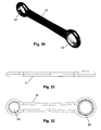
- the part 41 is as well made of a composite material and has at its ends a hole 54 and in another hole a pivotable ring 53, made of a metal and especially titanium.
- the rings 50 and 53 are disposed at the ends where the nuts 48 and clamps are arranged.
Abstract
Description
- The present invention relates to an elongated stabilization members and a bone interface anchor for use with such elongated stabilization members.
- In prior art
EP-A-0 755 228 discloses a stabilization member and a bone interface anchor, wherein the stabilization member is a rod. The anchor has a retaining member which has a channel which is adapted to receive said rod and compression means for compressively securing the stabilization member in the retaining member with the compression means. With a downward compression force can be applied on the rod to bias it against a screw head. -
EP-A-0 934 027 describes a multi-axial bone crew assembly, which comprises a crown member for engagement with the bone crew. With a compression member a rod is pressed against said crown member and said crown member is pressed against the head of a bone screw. -
EP-A-1 240 875 discloses a spinal osteosynthesis member which has inside a U-shaped opening of the connector a ring cable of coming into contact with the head of a bone screw. A rod is inserted into the U-shaped opening and biased with a locking member against said ring to the head of a pedicle screw. -
- The invention relates to an elongated stabilization member useful in bone and especially spinal repair processes. The elongated stabilization member comprises a composite rod having a uniform cross-section essentially throughout its length and said rod having first and second segments each of which has a different modulus of elasticity. The stabilization member of the present invention has the advantage that I can approach the modular elasticity of bone without any danger of breakage. It further provides limited motion to the connected bones and can fulfill the biomechanical requirement which are needed to increase the muscle as well as the strength of the bones to which the muscles are connected. The rod can have variable stress characteristics throughout its length and a uniform cross-section essentially throughout its length. The uniform cross-section makes it possible to use the rod with almost any of the standard connectors. As the rod is made from composite it has the advantage of enhanced imaging throughout the length of the rod. The invention is especially useful for treatment of spinal bone cancer which requires radiation treatment in addition to stabilization, wherein it facilitates proper dosage of radiation adjoint to the implant.
-
- Figure 1
- is an exploded perspective view of the components of the bone interface anchor and the elongated stabilization member according to one exemplary embodiment of the invention,
- Figure 2
- is a cross-sectional view of the anchor and stabilization member in the assembled state,
- Figure 3
- is a side view of the anchor according to an alternative embodiment of the invention,
- Figure 4
- is a partial cross-sectional view of the anchor as shown in
Fig. 3 , - Figure 5
- is another partial cross-sectional view of the anchor as shown in
Fig. 3 , - Figure 6
- is a cross-section of the anchor taken along line VI-VI shown in
Fig. 3 , - Figure 7
- is a side view of the anchor according to an alternative embodiment of the invention,
- Figure 8
- is a partial cross-sectional view of the anchor as shown in
Fig. 7 , - Figure 9
- is another partial cross-sectional view of the anchor as shown in
Fig. 7 , - Figure 10
- is a cross-section of the anchor taken along line X-X shown in
Fig. 7 , - Fig. 11-19
- cross-sections of the elongated stabilization member,
- Figure 20
- is a perspective view of a transverse connector,
- Figure 21
- is a perspective view of a part of a transverse connector
- Figure 22
- is an exploded perspective view of the part shown in
Fig. 21 , - Figure 23
- is a cross-sectional view of the part shown in
Fig. 23 , - Figure 24
- is another exploded perspective view of the part shown in
Fig. 21 , - Figure 25
- is a perspective view of a transverse connector having two longitudinal elements connected via an articulation,
- Figure 26
- is another perspective view of the transverse connector shown in
Fig. 25 , - Figure 27
- is another perspective view of the transverse connector shown in
Fig. 25 , - Figure 28
- is a perspective view of a part of the connector shown in
Fig. 25 , - Figure 29
- is an exploded perspective view of the part shown in
Fig. 28 , - Figure 30
- is a perspective view of another part of the connector shown in
Fig. 25 , - Figure 31
- is a side view of the part shown in
Fig. 30 , - Figure 32
- is another view of the part shown in
Fig. 30 and - Figure 33
- is an exploded perspective view of the part shown in
Fig. 30 . -
Figures 1 and 2 show the components of thebone interface anchor 1 and a stabilization member, especially a rod R which is camped as shown inFigure 2 . The components of theanchor 1 include a compression member, especially a not 10, areceptor 18, acrown member 12 and abone screw 2. Thenut 10 is disposed within abore 4 of thereceptor 18 for engagement with the rod R and bias the rod R against acrown member 12 which engages ahead 14 of thescrew 2 at a concave surface 9 (Fig. 1 ). The invention is disclosed with a bone screw, but other bone fixation members could be used instead. - The
receptor 18 has a threadedportion 7 configured to engage thenut 10 which has a correspondingouter thread 22. Thenut 10 also includes atool recess 11 which can be a hex recess. - The rod R is locked between the
nut 10 and thecrown member 12. The upper side of thecrown member 12 has agroove 5 which engages the rod R. Thisgroove 5 increases the contact surface to the rod R and therefore thecrown member 12 can be better propagate forces. The rod R is gripped tighter and with less deformation. The rod R as illustrated inFigure 1 has a round cross section. It is envisioned that the rod R can have other cross sections, wherein the groove is made correspondingly. - The
crown member 12 has abottom surface 6 which is vex and especially spherical. Thissurface 6 engages theconcave surface 9 of thescrew head 14 which is preferably spherical as well. Thesurfaces screw head 14 and aconcave surface 3 at the bottom of thebore 4. Within theconcave surface 3 there is anopening 15 for receiving thescrew 2. Thescrew 2 has ashank 29 with arecess 17. The diameter of theshank 29 at therecess 17 is smaller than the diameter of theopening 15. Theopening 15 can be round or oval. - When the
nut 10 is not tightened, thereceptor 18 is pivotable with respect to the longitudinal axis of thescrew 2. In order to fix the rod R, the surgeon tightens thenut 10. The pressure between thenut 10, the rod R, thecrown member 12, thescrew head 14 and the bottom of thereceptor 18 secures the assembly regardless of the angle between thescrew 2 and thereceptor 18. - The fixed rod R not only connects the vertebra to be fused, it s well exerts stable pressure upon the
crown member 12. In order to have enough friction between thesurface 3 of thereceptor 18, thecrown member 12 is made with a comparatively large mass. Furthermore, thecrown member 12 has the shape of a saddle and engages the rod R with a comparatively large surface. Thecrown member 12 can therefore without much loss propagate the force to thescrew head 14 and therefore effects a solid fixation regardless of the angle between thescrew 2 and thereceptor 18. It has been shown that the anchor is especially suitable for a rod R made from a composite material, and especially a composite material with carbon fibers disposed therein. When the rod R is made from a composite material, there is almost no friction between thenut 10 and the rod R. Therefore, almost all of the pressure from the torque exerted on thenut 10 is upon the rod R and upon the threads of the anchor. When the rod R is made of titanium, there is considerably more friction between thenut 10 and the rod R and this friction absorbs part of the torque and part of the pressure, placing less stress on the threads and less pressure on the rod R. - The rod R is especially suitable in combination with the anchor, when it contains
fibers 30 and especially carbon fibers as illustrate inFigures 11 to 19 . Thesefibers 30 not only affect stiffness between vertebrae, but at the same time thefibers 30 propagate the pressure from thenut 10 to thecrown member 12. Thefibers 30 make thecrown member 12 work biomechanically, because they transmit the force to thecrown member 12. Therod 10 is preferably anisotropic and has both the ability to exert a steady pressure and a control motion between fused vertebral bones. - The
Figures 3 to 6 disclose an anchor 1' which has a screw 2', provided with acollar 23 disposed within arecess 21. Thecollar 23 is provided with a comparatively large surface. -
Figures 7 to 10 show analternative anchor 1" which has athread 24 which is made corresponding to thethread 25 of thereceptor 18". - The rods R as illustrated in
Figure 11 has a first segment A, a second segment B and a third segment C which have different moduli of elasticity. The modulus of elasticity in the second segment B is lower than in the segments A and C. The rod R may have more than three segments or only two segments as illustrated inFigure 12 . - The reinforcement of the rod R with
fibers 30 helps to eliminate creep and spreads the load more evenly over a larger area. With the different moduli of elasticity it is possible to control motion between fused vertebral bones. The rod R can provide limited motion to the fused bones which helps to increase the muscle as well the strength of the bones to which the muscles are connected. - The sections A and C as shown in
Figure 11 containplies fibers 30 and especially carbon fibers. Thefibers 30 of theply 26 and ply 28 are mainly parallel to the longitudinal direction of the rod R, whereas the fibers of theply 27 are crossed and oblique to the longitudinal direction of the rod R. Theplies ply 27. - The
plies Figures 13 to 19. Figure 13 shows a segment withplies Figure 13 has therefore a stiffness which is between the high stiffness of segment A and the lower stiffness of segment B. -
Figure 14 shows a segment made withplies 26 and has therefore a comparatively high stiffness, whereas the segment shown inFigure 15 is made withsegments 27 and has therefore a comparatively low stiffness. -
Figures 16 to 19 show other possibilities to make segments with different moduli of elasticity. To provide different moduli of elasticity, segments can have different densities of fibers and/or fibers of different lengths. -
Figures 20 to 24 disclose atransverse connector 31 comprising arod 32 made from a carbon composite material, twostiffener connectors 35. Therod 32 is clamped at its ends withnuts 37 which exert a pressure force on thestiffness rod 32. Theconnectors 35 could be the tulip anchors as shown inFigures 1 to 10 and therod 32 could be a rod R as disclosed inFigures 11 to 19 . - The
stiffeners Figure 20 , thestiffeners transverse connector 31 can for example have a higher stiffness in the area of thestiffener 33 than in the area of thestiffener 34, as thestiffener 33 is longer than thestiffener 34. The stiffener 33' as shown inFigures 21 to 24 has ahole 39, which lowers the stiffness compared with a stiffener without this hole. - The
rod 32 preferably containscarbon fibers 30 as shown inFigures 11 to 19 . A part of these fibers have a direction which is oblique to the longitudinal direction of therod 32. These fibers have the effect that they prevent deformation of therod 32 due to the pressure of thenut 10. The cross-section of therod 32 does therefore essentially not change when the rod is clamped with a comparatively high pressure. The cross-section even does not change later when the connector is implanted. The same feature relates to the rod R shown inFigures 11 to 19 . -
Figures 25 to 33 show atransverse connector 40 comprising a firstlongitudinal element 41, a secondlongitudinal element 3, anarticulation 43, which connects theelements clamps 47. With theclamps 47 and the nuts 48 thetransverse connector 40 is connected with stabilization rods as shown inFigures 1 and 2 . Theelement 42 comprises anoblong hole 49 which allows to vary the angel between the two elements and the distance. Within a hole 51 aring 50 is pivotably disposed which is made of a metal, for example titanium. Theelements elements part 41 is as well made of a composite material and has at its ends ahole 54 and in another hole apivotable ring 53, made of a metal and especially titanium. Therings -
- 1
- bone interface anchor
- 2
- screw
- 3
- surface
- 4
- bore
- 5
- groove
- 6
- surface
- 7
- thread
- 8
- surface
- 9
- surface
- 10
- compression means
- 11
- tool recess
- 12
- crown member
- 13
- channel
- 14
- screw head
- 15
- opening
- 16
- thread
- 17
- recess
- 18
- receptor
- 19
- tool recess
- 20
- opening
- 21
- recess
- 22
- thread
- 23
- collar
- 24
- thread
- 25
- thread
- 26
- ply
- 27
- ply
- 28
- ply
- 29
- shank
- 30
- fibers
- 31
- transverse connector
- 32
- longitudinal element (rod)
- 33
- stiffener
- 34
- stiffener
- 35
- connector (anchor)
- 36
- thread
- 37
- nut
- 38
- bore
- 39
- hole
- 40
- transverse connector
- 41
- first longitudinal element
- 42
- second longitudinal element
- 43
- articulation
- 44
- nut
- 45
- disk
- 46
- screw
- 47
- clamp
- 48
- nut
- 49
- oblong hole
- 50
- ring
- 51
- hole
- 52
- hole
- 53
- ring
- 54
- hole
- A
- segment
- B
- segment
- C
- segment
- R
- rod
Claims (22)
- An elongated stabilization member useful in bone and especially spinal repair processes comprising:a composite rod having a uniform cross-section essentially throughout its length andsaid rod having at least first and second segments each of which has a different modulus of elasticity.
- The composite rod of claim 1, wherein said rod is comprised of plastic with carbon fibers disposed therein and said first and second segments have different orientation of fiber to provide said different moduli of elasticity.
- The composite rod of claim 1, wherein the ratio direction of fiber to plastic varies along the rod length.
- The composite rod of claim 1, wherein said plastic and fibers of said rod will not block imaging rays.
- The composite rod of claim 1, wherein said rod is comprised with carbon fibers disposed therein and said first and second segments have different densities of fibers to provide said different moduli of elasticity.
- The composite rod of claim 1, wherein said rod is comprises with carbon fibers disposed therein and said first and second segments have fibers of different lengths to provide said different moduli of elasticity.
- An elongate rod for location approximately parallel to and adjacent to a spine,
said rod having a uniform cross-section throughout its length and is comprised of fiber reinforced plastic, and
said rod having moduli of elasticity along its length corresponding to, but less than, the moduli of elasticity of the spine segments closest to said rod segments. - A device for treating a human spine having a series of bone segments comprising:a composite rod having a uniform cross-sectional dimension throughout its length,said rod comprising a plurality of rod segments each having a different modulus of elasticity,first and second anchors adapted to be secured to said rod in spaced relationship to one another, andeach of said anchors including a screw which is adapted to secure said anchors to spaced spinal bone segments.
- The device of claim 8, wherein each of said anchors has a bottom surface facing a spinal bone segment,
means to slidably receive said screw in said anchors, and
lock means to affix said anchors to said rod. - The device of claim 9, wherein said anchors, said screws and said lock means are made of a carbon reinforced plastic that will not block imaging rays and facilitate radiation treatment.
- The device of claim 10, wherein first and second anchors of composite material are adapted to be secured to said rod in spaced relationship to one another and each of said anchors includes a screw adapted to secure said anchors to spaced bone segments of the spine.
- A device for treating a human spine having a series of bone segments comprising:a composite rod having a uniform cross-sectional dimension throughout its length,said rod comprising a plurality of rod segments each having a different modulus of elasticity,first and second anchors adapted to be secured to said rod in spaced relationship to one another,each of said anchors including a screw which is adapted to secure said anchors to spaced spinal bone segments,each of said anchors having a bottom surface facing a spinal bone segment,means securing said screws to said anchors such that said screws can be variably positioned relative to said anchors, andlock means to fix said anchors to said rods after positioning.
- A bone interface anchor for use with a composite stabilizer rod said anchor comprising:a receptor having retaining means for receiving said stabilizer,a compression assembly for securing said stabilizer within said receptor,bone fixation screws which secure said anchors relative to bone segments of the human spine,said receptor having a surface forming a mating cooperation with said screw such that said receptor can be variably positioned relative to said screw,lock means to fix said screw relative to said receptor, andsaid retaining means having a crown member between said stabilizer and the interior of said receptor.
- The bone interface anchor of claim 13, wherein said composite rod has a uniform cross-section throughout its length, and
said rod having first and second segments each of which as a different modulus of elasticity. - The bone interface anchor of claim 14, wherein said rod is comprised of plastic with carbon fibers disposed therein and said first and second segments have different direction or densities of fiber to provide said different moduli of elasticity.
- The bone interface anchor of claim 14, wherein the ratio density of fiber to plastic varies along the rod length.
- The bone interface anchor of claim 13, wherein the plastic and fibers of said rod an said anchor will not block imaging rays.
- An assembly for the stabilization of one or more spinal bone segments, comprising:first and second anchors,an elongated composite rod having a uniform cross-section throughout its length,first and second screws each having enlarged heads received respectively by saidfirst and second screws and said anchors and which secure said anchors to a spinal bone segment,said anchors having cylindrical side walls with a reduced bottom opening of lesser diameter than said heads which retain said heads in a manner providing limited universal movement of said screws with respect to said anchors,said anchors each having a reception channel 13 to receive said composite rod, a crown member disposed between said heads and said rod,said crown members each having a grove formed therein to receive said rod and space said rod from said heads, andmeans to compress said rod against said crowns and said crowns against said heads to fix their relationship to one another after the angular disposition of said screws have been selected.
- The assembly of claim 18, wherein said composite rod is comprised of plastic with carbon reinforcing fibers disposed therein, the density of said fibers providing selected moduli of elasticity throughout the length by varying fiber density.
- The assembly of claim 19, wherein the components of said anchors are of reinforced plastic that will not block imaging rays.
- The assembly of claim 18, wherein the rod contains fibers directed to prevent deformation of the rod due to the pressure of the anchor.
- A rod useful in bone and especially spinal repair processes, made of plastic with fibers disposed therein, wherein at least a part of the fibers are directed to prevent expansion of the rod with respect to its cross-section.
Applications Claiming Priority (1)
| Application Number | Priority Date | Filing Date | Title |
|---|---|---|---|
| US90717507P | 2007-03-23 | 2007-03-23 |
Publications (3)
| Publication Number | Publication Date |
|---|---|
| EP1972289A2 true EP1972289A2 (en) | 2008-09-24 |
| EP1972289A3 EP1972289A3 (en) | 2009-05-13 |
| EP1972289B1 EP1972289B1 (en) | 2018-10-17 |
Family
ID=39632474
Family Applications (1)
| Application Number | Title | Priority Date | Filing Date |
|---|---|---|---|
| EP08405084.8A Not-in-force EP1972289B1 (en) | 2007-03-23 | 2008-03-19 | Elongated stabilization member and bone anchor useful in bone and especially spinal repair processes |
Country Status (2)
| Country | Link |
|---|---|
| US (2) | US8317833B2 (en) |
| EP (1) | EP1972289B1 (en) |
Cited By (2)
| Publication number | Priority date | Publication date | Assignee | Title |
|---|---|---|---|---|
| CN104661607A (en) * | 2012-07-24 | 2015-05-27 | 卡波菲克斯整形有限责任公司 | Spine system and kit |
| USD956233S1 (en) * | 2020-04-24 | 2022-06-28 | Solco Biomedical Co., Ltd. | Cervical screw |
Families Citing this family (79)
| Publication number | Priority date | Publication date | Assignee | Title |
|---|---|---|---|---|
| US7833250B2 (en) | 2004-11-10 | 2010-11-16 | Jackson Roger P | Polyaxial bone screw with helically wound capture connection |
| US10258382B2 (en) | 2007-01-18 | 2019-04-16 | Roger P. Jackson | Rod-cord dynamic connection assemblies with slidable bone anchor attachment members along the cord |
| US8353932B2 (en) | 2005-09-30 | 2013-01-15 | Jackson Roger P | Polyaxial bone anchor assembly with one-piece closure, pressure insert and plastic elongate member |
| US10729469B2 (en) | 2006-01-09 | 2020-08-04 | Roger P. Jackson | Flexible spinal stabilization assembly with spacer having off-axis core member |
| US8292926B2 (en) | 2005-09-30 | 2012-10-23 | Jackson Roger P | Dynamic stabilization connecting member with elastic core and outer sleeve |
| US7862587B2 (en) | 2004-02-27 | 2011-01-04 | Jackson Roger P | Dynamic stabilization assemblies, tool set and method |
| US8876868B2 (en) | 2002-09-06 | 2014-11-04 | Roger P. Jackson | Helical guide and advancement flange with radially loaded lip |
| US7621918B2 (en) | 2004-11-23 | 2009-11-24 | Jackson Roger P | Spinal fixation tool set and method |
| US7377923B2 (en) | 2003-05-22 | 2008-05-27 | Alphatec Spine, Inc. | Variable angle spinal screw assembly |
| US8926670B2 (en) | 2003-06-18 | 2015-01-06 | Roger P. Jackson | Polyaxial bone screw assembly |
| US8092500B2 (en) | 2007-05-01 | 2012-01-10 | Jackson Roger P | Dynamic stabilization connecting member with floating core, compression spacer and over-mold |
| US8137386B2 (en) | 2003-08-28 | 2012-03-20 | Jackson Roger P | Polyaxial bone screw apparatus |
| US7967850B2 (en) | 2003-06-18 | 2011-06-28 | Jackson Roger P | Polyaxial bone anchor with helical capture connection, insert and dual locking assembly |
| US8398682B2 (en) | 2003-06-18 | 2013-03-19 | Roger P. Jackson | Polyaxial bone screw assembly |
| US8814911B2 (en) | 2003-06-18 | 2014-08-26 | Roger P. Jackson | Polyaxial bone screw with cam connection and lock and release insert |
| US7776067B2 (en) | 2005-05-27 | 2010-08-17 | Jackson Roger P | Polyaxial bone screw with shank articulation pressure insert and method |
| US8377102B2 (en) * | 2003-06-18 | 2013-02-19 | Roger P. Jackson | Polyaxial bone anchor with spline capture connection and lower pressure insert |
| US7766915B2 (en) | 2004-02-27 | 2010-08-03 | Jackson Roger P | Dynamic fixation assemblies with inner core and outer coil-like member |
| US11419642B2 (en) | 2003-12-16 | 2022-08-23 | Medos International Sarl | Percutaneous access devices and bone anchor assemblies |
| US7527638B2 (en) | 2003-12-16 | 2009-05-05 | Depuy Spine, Inc. | Methods and devices for minimally invasive spinal fixation element placement |
| US7179261B2 (en) | 2003-12-16 | 2007-02-20 | Depuy Spine, Inc. | Percutaneous access devices and bone anchor assemblies |
| US8152810B2 (en) | 2004-11-23 | 2012-04-10 | Jackson Roger P | Spinal fixation tool set and method |
| US7160300B2 (en) | 2004-02-27 | 2007-01-09 | Jackson Roger P | Orthopedic implant rod reduction tool set and method |
| EP1720468A4 (en) | 2004-02-27 | 2010-01-27 | Roger P Jackson | Orthopedic implant rod reduction tool set and method |
| US11241261B2 (en) | 2005-09-30 | 2022-02-08 | Roger P Jackson | Apparatus and method for soft spinal stabilization using a tensionable cord and releasable end structure |
| US7651502B2 (en) | 2004-09-24 | 2010-01-26 | Jackson Roger P | Spinal fixation tool set and method for rod reduction and fastener insertion |
| JP2008519656A (en) | 2004-11-10 | 2008-06-12 | ロジャー・ピー・ジャクソン | Helical guide and forward flange with break extension |
| US8926672B2 (en) | 2004-11-10 | 2015-01-06 | Roger P. Jackson | Splay control closure for open bone anchor |
| US9980753B2 (en) | 2009-06-15 | 2018-05-29 | Roger P Jackson | pivotal anchor with snap-in-place insert having rotation blocking extensions |
| US8308782B2 (en) | 2004-11-23 | 2012-11-13 | Jackson Roger P | Bone anchors with longitudinal connecting member engaging inserts and closures for fixation and optional angulation |
| WO2006057837A1 (en) | 2004-11-23 | 2006-06-01 | Jackson Roger P | Spinal fixation tool attachment structure |
| US9216041B2 (en) | 2009-06-15 | 2015-12-22 | Roger P. Jackson | Spinal connecting members with tensioned cords and rigid sleeves for engaging compression inserts |
| US9168069B2 (en) | 2009-06-15 | 2015-10-27 | Roger P. Jackson | Polyaxial bone anchor with pop-on shank and winged insert with lower skirt for engaging a friction fit retainer |
| US8444681B2 (en) | 2009-06-15 | 2013-05-21 | Roger P. Jackson | Polyaxial bone anchor with pop-on shank, friction fit retainer and winged insert |
| US9918745B2 (en) | 2009-06-15 | 2018-03-20 | Roger P. Jackson | Polyaxial bone anchor with pop-on shank and winged insert with friction fit compressive collet |
| US7901437B2 (en) | 2007-01-26 | 2011-03-08 | Jackson Roger P | Dynamic stabilization member with molded connection |
| US10076361B2 (en) | 2005-02-22 | 2018-09-18 | Roger P. Jackson | Polyaxial bone screw with spherical capture, compression and alignment and retention structures |
| US8105368B2 (en) | 2005-09-30 | 2012-01-31 | Jackson Roger P | Dynamic stabilization connecting member with slitted core and outer sleeve |
| CA2670988C (en) | 2006-12-08 | 2014-03-25 | Roger P. Jackson | Tool system for dynamic spinal implants |
| US8475498B2 (en) | 2007-01-18 | 2013-07-02 | Roger P. Jackson | Dynamic stabilization connecting member with cord connection |
| US8366745B2 (en) | 2007-05-01 | 2013-02-05 | Jackson Roger P | Dynamic stabilization assembly having pre-compressed spacers with differential displacements |
| US8012177B2 (en) | 2007-02-12 | 2011-09-06 | Jackson Roger P | Dynamic stabilization assembly with frusto-conical connection |
| US8979904B2 (en) | 2007-05-01 | 2015-03-17 | Roger P Jackson | Connecting member with tensioned cord, low profile rigid sleeve and spacer with torsion control |
| US10383660B2 (en) | 2007-05-01 | 2019-08-20 | Roger P. Jackson | Soft stabilization assemblies with pretensioned cords |
| US20090234388A1 (en) * | 2008-03-15 | 2009-09-17 | Warsaw Orthopedic, Inc. | Spinal Stabilization Connecting Element and System |
| US20090248083A1 (en) * | 2008-03-26 | 2009-10-01 | Warsaw Orthopedic, Inc. | Elongated connecting element with varying modulus of elasticity |
| EP2113216B1 (en) * | 2008-04-28 | 2012-05-30 | Biedermann Technologies GmbH & Co. KG | Rod-shaped element for spinal stabilization and method for producing the same |
| US9017384B2 (en) * | 2008-05-13 | 2015-04-28 | Stryker Spine | Composite spinal rod |
| EP2442739A1 (en) | 2008-08-01 | 2012-04-25 | Jackson, Roger P. | Longitudinal connecting member with sleeved tensioned cords |
| US8382809B2 (en) * | 2008-10-17 | 2013-02-26 | Omni Surgical | Poly-axial pedicle screw implements and lock screw therefor |
| US8998959B2 (en) | 2009-06-15 | 2015-04-07 | Roger P Jackson | Polyaxial bone anchors with pop-on shank, fully constrained friction fit retainer and lock and release insert |
| US11229457B2 (en) | 2009-06-15 | 2022-01-25 | Roger P. Jackson | Pivotal bone anchor assembly with insert tool deployment |
| US9668771B2 (en) | 2009-06-15 | 2017-06-06 | Roger P Jackson | Soft stabilization assemblies with off-set connector |
| US8236035B1 (en) | 2009-06-16 | 2012-08-07 | Bedor Bernard M | Spinal fixation system and method |
| US20110029018A1 (en) * | 2009-07-30 | 2011-02-03 | Warsaw Othropedic, Inc | Variable resistance spinal stablization systems and methods |
| WO2011043799A1 (en) | 2009-10-05 | 2011-04-14 | Coligne Ag | Spinal fixation system and screwdriver tool for use with the same |
| AU2010303934B2 (en) | 2009-10-05 | 2014-03-27 | Roger P. Jackson | Polyaxial bone anchor with non-pivotable retainer and pop-on shank, some with friction fit |
| US8449578B2 (en) * | 2009-11-09 | 2013-05-28 | Ebi, Llc | Multiplanar bone anchor system |
| US9044272B2 (en) | 2009-11-09 | 2015-06-02 | Ebi, Llc | Multiplanar bone anchor system |
| EP2613719A1 (en) | 2010-09-08 | 2013-07-17 | Roger P. Jackson | Dynamic stabilization members with elastic and inelastic sections |
| EP2637584A4 (en) | 2010-10-15 | 2015-01-28 | Alphatec Holdings Inc | Fixation screw assembly |
| JP2013545527A (en) | 2010-11-02 | 2013-12-26 | ロジャー・ピー・ジャクソン | Multi-axis bone anchor with pop-on shank and pivotable retainer |
| WO2012128825A1 (en) | 2011-03-24 | 2012-09-27 | Jackson Roger P | Polyaxial bone anchor with compound articulation and pop-on shank |
| US8911479B2 (en) | 2012-01-10 | 2014-12-16 | Roger P. Jackson | Multi-start closures for open implants |
| WO2014005236A1 (en) * | 2012-07-05 | 2014-01-09 | Spinesave Ag | Elastic rod having different degrees of stiffness for the surgical treatment of the spine |
| US9510866B2 (en) * | 2012-08-15 | 2016-12-06 | Blackstone Medical, Inc. | Pivoting spinal fixation devices |
| US8911478B2 (en) | 2012-11-21 | 2014-12-16 | Roger P. Jackson | Splay control closure for open bone anchor |
| US10058354B2 (en) | 2013-01-28 | 2018-08-28 | Roger P. Jackson | Pivotal bone anchor assembly with frictional shank head seating surfaces |
| US8852239B2 (en) | 2013-02-15 | 2014-10-07 | Roger P Jackson | Sagittal angle screw with integral shank and receiver |
| CN105682583B (en) | 2013-09-01 | 2019-01-04 | 碳固定因骨科有限责任公司 | composite material spinal implant |
| US9987047B2 (en) | 2013-10-07 | 2018-06-05 | Spine Wave, Inc. | Translating polyaxial screw |
| US9566092B2 (en) | 2013-10-29 | 2017-02-14 | Roger P. Jackson | Cervical bone anchor with collet retainer and outer locking sleeve |
| US9717533B2 (en) | 2013-12-12 | 2017-08-01 | Roger P. Jackson | Bone anchor closure pivot-splay control flange form guide and advancement structure |
| US9451993B2 (en) | 2014-01-09 | 2016-09-27 | Roger P. Jackson | Bi-radial pop-on cervical bone anchor |
| US9597119B2 (en) | 2014-06-04 | 2017-03-21 | Roger P. Jackson | Polyaxial bone anchor with polymer sleeve |
| US10064658B2 (en) | 2014-06-04 | 2018-09-04 | Roger P. Jackson | Polyaxial bone anchor with insert guides |
| USD856509S1 (en) | 2016-09-28 | 2019-08-13 | Coligne Ag | Pedicle screw |
| US10610265B1 (en) | 2017-07-31 | 2020-04-07 | K2M, Inc. | Polyaxial bone screw with increased angulation |
| JP7446965B2 (en) * | 2020-09-29 | 2024-03-11 | グローブライド株式会社 | Spinal fixation rod |
Citations (12)
| Publication number | Priority date | Publication date | Assignee | Title |
|---|---|---|---|---|
| US4743260A (en) | 1985-06-10 | 1988-05-10 | Burton Charles V | Method for a flexible stabilization system for a vertebral column |
| EP0706876A1 (en) | 1994-10-14 | 1996-04-17 | Acromed Corporation | Composite structure and method of forming same |
| EP0755228A1 (en) | 1993-11-19 | 1997-01-29 | Cross Medical Products, Inc. | Variable locking stabilizer anchor seat and screw |
| EP0934027A1 (en) | 1996-09-24 | 1999-08-11 | SDGI Holdings, Inc. | Multi-axial bone screw assembly |
| WO2002002024A1 (en) | 1999-06-30 | 2002-01-10 | Surgival Co., S.A. | Polyaxial vertebral fixing system |
| EP1238637A1 (en) | 2001-03-09 | 2002-09-11 | Co-Ligne AG | Longitudinal implant |
| EP1240875A1 (en) | 2001-03-15 | 2002-09-18 | Stryker Spine | Spinal anchor with locking collar |
| WO2005016161A1 (en) | 2003-07-25 | 2005-02-24 | Traiber, S.A. | Vertebral fixation device for the treatment of spondylolisthesis |
| US20060041259A1 (en) | 2003-05-23 | 2006-02-23 | Paul David C | Spine stabilization system |
| WO2006083773A2 (en) | 2005-02-03 | 2006-08-10 | Harris Corporation | Method and apparatus for sealing flex circuits having heat sensitive circuit elements |
| US20070005063A1 (en) | 2005-06-20 | 2007-01-04 | Sdgi Holdings, Inc. | Multi-level multi-functional spinal stabilization systems and methods |
| US20070016190A1 (en) | 2005-07-14 | 2007-01-18 | Medical Device Concepts Llc | Dynamic spinal stabilization system |
Family Cites Families (19)
| Publication number | Priority date | Publication date | Assignee | Title |
|---|---|---|---|---|
| US5415661A (en) * | 1993-03-24 | 1995-05-16 | University Of Miami | Implantable spinal assist device |
| US5733286A (en) * | 1997-02-12 | 1998-03-31 | Third Millennium Engineering, Llc | Rod securing polyaxial locking screw and coupling element assembly |
| US6113601A (en) * | 1998-06-12 | 2000-09-05 | Bones Consulting, Llc | Polyaxial pedicle screw having a loosely coupled locking cap |
| CA2423973A1 (en) * | 1999-09-27 | 2001-04-05 | Blackstone Medical, Inc. | A surgical screw system and related methods |
| EP1174092A3 (en) * | 2000-07-22 | 2003-03-26 | Corin Spinal Systems Limited | A pedicle attachment assembly |
| US6692500B2 (en) * | 2001-10-15 | 2004-02-17 | Gary Jack Reed | Orthopedic stabilization device and method |
| WO2004096066A2 (en) * | 2003-04-25 | 2004-11-11 | Kitchen Michael S | Spinal curvature correction device |
| US6986771B2 (en) * | 2003-05-23 | 2006-01-17 | Globus Medical, Inc. | Spine stabilization system |
| US20050203513A1 (en) * | 2003-09-24 | 2005-09-15 | Tae-Ahn Jahng | Spinal stabilization device |
| US20060200245A1 (en) * | 2005-03-07 | 2006-09-07 | Sdgi Holdings, Inc. | Materials, devices, and methods for in-situ formation of composite intervertebral implants |
| US20060235385A1 (en) * | 2005-03-31 | 2006-10-19 | Dale Whipple | Low profile polyaxial screw |
| US20060247638A1 (en) * | 2005-04-29 | 2006-11-02 | Sdgi Holdings, Inc. | Composite spinal fixation systems |
| US7951171B2 (en) * | 2005-05-04 | 2011-05-31 | K2M, Inc. | Polyaxial surgical rod fixation assembly |
| US20060276788A1 (en) * | 2005-05-26 | 2006-12-07 | Amedica Corporation | Osteoconductive spinal fixation system |
| US20070270821A1 (en) * | 2006-04-28 | 2007-11-22 | Sdgi Holdings, Inc. | Vertebral stabilizer |
| EP1857065B1 (en) * | 2006-05-16 | 2010-08-25 | BIEDERMANN MOTECH GmbH | Longitudinal member for use in spinal or trauma surgery |
| US20090093846A1 (en) * | 2007-10-04 | 2009-04-09 | Zimmer Spine Inc. | Pre-Curved Flexible Member For Providing Dynamic Stability To A Spine |
| US8043339B2 (en) * | 2007-10-24 | 2011-10-25 | Zimmer Spine, Inc. | Flexible member for use in a spinal column and method for making |
| US9232968B2 (en) * | 2007-12-19 | 2016-01-12 | DePuy Synthes Products, Inc. | Polymeric pedicle rods and methods of manufacturing |
-
2008
- 2008-03-19 EP EP08405084.8A patent/EP1972289B1/en not_active Not-in-force
- 2008-03-24 US US12/053,870 patent/US8317833B2/en active Active
-
2012
- 2012-10-26 US US13/661,754 patent/US20130053889A1/en not_active Abandoned
Patent Citations (12)
| Publication number | Priority date | Publication date | Assignee | Title |
|---|---|---|---|---|
| US4743260A (en) | 1985-06-10 | 1988-05-10 | Burton Charles V | Method for a flexible stabilization system for a vertebral column |
| EP0755228A1 (en) | 1993-11-19 | 1997-01-29 | Cross Medical Products, Inc. | Variable locking stabilizer anchor seat and screw |
| EP0706876A1 (en) | 1994-10-14 | 1996-04-17 | Acromed Corporation | Composite structure and method of forming same |
| EP0934027A1 (en) | 1996-09-24 | 1999-08-11 | SDGI Holdings, Inc. | Multi-axial bone screw assembly |
| WO2002002024A1 (en) | 1999-06-30 | 2002-01-10 | Surgival Co., S.A. | Polyaxial vertebral fixing system |
| EP1238637A1 (en) | 2001-03-09 | 2002-09-11 | Co-Ligne AG | Longitudinal implant |
| EP1240875A1 (en) | 2001-03-15 | 2002-09-18 | Stryker Spine | Spinal anchor with locking collar |
| US20060041259A1 (en) | 2003-05-23 | 2006-02-23 | Paul David C | Spine stabilization system |
| WO2005016161A1 (en) | 2003-07-25 | 2005-02-24 | Traiber, S.A. | Vertebral fixation device for the treatment of spondylolisthesis |
| WO2006083773A2 (en) | 2005-02-03 | 2006-08-10 | Harris Corporation | Method and apparatus for sealing flex circuits having heat sensitive circuit elements |
| US20070005063A1 (en) | 2005-06-20 | 2007-01-04 | Sdgi Holdings, Inc. | Multi-level multi-functional spinal stabilization systems and methods |
| US20070016190A1 (en) | 2005-07-14 | 2007-01-18 | Medical Device Concepts Llc | Dynamic spinal stabilization system |
Cited By (2)
| Publication number | Priority date | Publication date | Assignee | Title |
|---|---|---|---|---|
| CN104661607A (en) * | 2012-07-24 | 2015-05-27 | 卡波菲克斯整形有限责任公司 | Spine system and kit |
| USD956233S1 (en) * | 2020-04-24 | 2022-06-28 | Solco Biomedical Co., Ltd. | Cervical screw |
Also Published As
| Publication number | Publication date |
|---|---|
| EP1972289A3 (en) | 2009-05-13 |
| US20080262548A1 (en) | 2008-10-23 |
| US8317833B2 (en) | 2012-11-27 |
| US20130053889A1 (en) | 2013-02-28 |
| EP1972289B1 (en) | 2018-10-17 |
Similar Documents
| Publication | Publication Date | Title |
|---|---|---|
| US8317833B2 (en) | Elongated stabilization member and bone anchor useful in bone and especially spinal repair processes | |
| US9931139B2 (en) | Dynamic stabilization connecting member with pre-tensioned solid core | |
| EP1800614B1 (en) | Dynamic stabilization device for bones or vertebrae | |
| US9216041B2 (en) | Spinal connecting members with tensioned cords and rigid sleeves for engaging compression inserts | |
| US8012177B2 (en) | Dynamic stabilization assembly with frusto-conical connection | |
| CA2690038C (en) | Dynamic stabilization connecting member with pre-tensioned solid core | |
| US9913668B2 (en) | Interspinous fixation implant | |
| US9451988B2 (en) | Rod-shaped implant in particular for stabilizing the spinal column and stabilization device including such a rod-shaped implant | |
| EP1663033B1 (en) | Bone fixation assembly and method | |
| EP3409225B1 (en) | Vertebral stabilization system | |
| US20070270832A1 (en) | Locking device and method, for use in a bone stabilization system, employing a set screw member and deformable saddle member | |
| US20050228382A1 (en) | Screw and rod fixation assembly and device | |
| US20080183223A1 (en) | Hybrid jointed bone screw system | |
| US20070233075A1 (en) | Spinal fixation device with variable stiffness | |
| EP2279706A1 (en) | Bone anchoring device | |
| US11224463B2 (en) | Dynamic stabilization connecting member with pre-tensioned flexible core member |
Legal Events
| Date | Code | Title | Description |
|---|---|---|---|
| PUAI | Public reference made under article 153(3) epc to a published international application that has entered the european phase |
Free format text: ORIGINAL CODE: 0009012 |
|
| AK | Designated contracting states |
Kind code of ref document: A2 Designated state(s): AT BE BG CH CY CZ DE DK EE ES FI FR GB GR HR HU IE IS IT LI LT LU LV MC MT NL NO PL PT RO SE SI SK TR |
|
| AX | Request for extension of the european patent |
Extension state: AL BA MK RS |
|
| RIN1 | Information on inventor provided before grant (corrected) |
Inventor name: LUENSMANN, DAVID Inventor name: OLSON, STEVE Inventor name: LANGE, ROBERT Inventor name: BIHL, ANDREAS |
|
| PUAL | Search report despatched |
Free format text: ORIGINAL CODE: 0009013 |
|
| AK | Designated contracting states |
Kind code of ref document: A3 Designated state(s): AT BE BG CH CY CZ DE DK EE ES FI FR GB GR HR HU IE IS IT LI LT LU LV MC MT NL NO PL PT RO SE SI SK TR |
|
| AX | Request for extension of the european patent |
Extension state: AL BA MK RS |
|
| 17P | Request for examination filed |
Effective date: 20091113 |
|
| AKX | Designation fees paid |
Designated state(s): AT BE BG CH CY CZ DE DK EE ES FI FR GB GR HR HU IE IS IT LI LT LU LV MC MT NL NO PL PT RO SE SI SK TR |
|
| 17Q | First examination report despatched |
Effective date: 20091229 |
|
| GRAP | Despatch of communication of intention to grant a patent |
Free format text: ORIGINAL CODE: EPIDOSNIGR1 |
|
| STAA | Information on the status of an ep patent application or granted ep patent |
Free format text: STATUS: GRANT OF PATENT IS INTENDED |
|
| INTG | Intention to grant announced |
Effective date: 20171020 |
|
| GRAJ | Information related to disapproval of communication of intention to grant by the applicant or resumption of examination proceedings by the epo deleted |
Free format text: ORIGINAL CODE: EPIDOSDIGR1 |
|
| STAA | Information on the status of an ep patent application or granted ep patent |
Free format text: STATUS: EXAMINATION IS IN PROGRESS |
|
| GRAP | Despatch of communication of intention to grant a patent |
Free format text: ORIGINAL CODE: EPIDOSNIGR1 |
|
| STAA | Information on the status of an ep patent application or granted ep patent |
Free format text: STATUS: GRANT OF PATENT IS INTENDED |
|
| INTC | Intention to grant announced (deleted) | ||
| INTG | Intention to grant announced |
Effective date: 20180320 |
|
| GRAS | Grant fee paid |
Free format text: ORIGINAL CODE: EPIDOSNIGR3 |
|
| RIN1 | Information on inventor provided before grant (corrected) |
Inventor name: LUENSMANN, DAVID Inventor name: LANGE, ROBERT Inventor name: BIHL, ANDREAS Inventor name: OLSON, STEVE |
|
| GRAA | (expected) grant |
Free format text: ORIGINAL CODE: 0009210 |
|
| STAA | Information on the status of an ep patent application or granted ep patent |
Free format text: STATUS: THE PATENT HAS BEEN GRANTED |
|
| AK | Designated contracting states |
Kind code of ref document: B1 Designated state(s): AT BE BG CH CY CZ DE DK EE ES FI FR GB GR HR HU IE IS IT LI LT LU LV MC MT NL NO PL PT RO SE SI SK TR |
|
| REG | Reference to a national code |
Ref country code: GB Ref legal event code: FG4D |
|
| REG | Reference to a national code |
Ref country code: CH Ref legal event code: EP |
|
| REG | Reference to a national code |
Ref country code: IE Ref legal event code: FG4D |
|
| REG | Reference to a national code |
Ref country code: DE Ref legal event code: R096 Ref document number: 602008057429 Country of ref document: DE Ref country code: AT Ref legal event code: REF Ref document number: 1053055 Country of ref document: AT Kind code of ref document: T Effective date: 20181115 |
|
| REG | Reference to a national code |
Ref country code: NL Ref legal event code: MP Effective date: 20181017 |
|
| REG | Reference to a national code |
Ref country code: SE Ref legal event code: TRGR |
|
| REG | Reference to a national code |
Ref country code: LT Ref legal event code: MG4D |
|
| REG | Reference to a national code |
Ref country code: AT Ref legal event code: MK05 Ref document number: 1053055 Country of ref document: AT Kind code of ref document: T Effective date: 20181017 |
|
| PG25 | Lapsed in a contracting state [announced via postgrant information from national office to epo] |
Ref country code: NL Free format text: LAPSE BECAUSE OF FAILURE TO SUBMIT A TRANSLATION OF THE DESCRIPTION OR TO PAY THE FEE WITHIN THE PRESCRIBED TIME-LIMIT Effective date: 20181017 |
|
| PG25 | Lapsed in a contracting state [announced via postgrant information from national office to epo] |
Ref country code: FI Free format text: LAPSE BECAUSE OF FAILURE TO SUBMIT A TRANSLATION OF THE DESCRIPTION OR TO PAY THE FEE WITHIN THE PRESCRIBED TIME-LIMIT Effective date: 20181017 Ref country code: BG Free format text: LAPSE BECAUSE OF FAILURE TO SUBMIT A TRANSLATION OF THE DESCRIPTION OR TO PAY THE FEE WITHIN THE PRESCRIBED TIME-LIMIT Effective date: 20190117 Ref country code: NO Free format text: LAPSE BECAUSE OF FAILURE TO SUBMIT A TRANSLATION OF THE DESCRIPTION OR TO PAY THE FEE WITHIN THE PRESCRIBED TIME-LIMIT Effective date: 20190117 Ref country code: LT Free format text: LAPSE BECAUSE OF FAILURE TO SUBMIT A TRANSLATION OF THE DESCRIPTION OR TO PAY THE FEE WITHIN THE PRESCRIBED TIME-LIMIT Effective date: 20181017 Ref country code: IS Free format text: LAPSE BECAUSE OF FAILURE TO SUBMIT A TRANSLATION OF THE DESCRIPTION OR TO PAY THE FEE WITHIN THE PRESCRIBED TIME-LIMIT Effective date: 20190217 Ref country code: LV Free format text: LAPSE BECAUSE OF FAILURE TO SUBMIT A TRANSLATION OF THE DESCRIPTION OR TO PAY THE FEE WITHIN THE PRESCRIBED TIME-LIMIT Effective date: 20181017 Ref country code: AT Free format text: LAPSE BECAUSE OF FAILURE TO SUBMIT A TRANSLATION OF THE DESCRIPTION OR TO PAY THE FEE WITHIN THE PRESCRIBED TIME-LIMIT Effective date: 20181017 Ref country code: ES Free format text: LAPSE BECAUSE OF FAILURE TO SUBMIT A TRANSLATION OF THE DESCRIPTION OR TO PAY THE FEE WITHIN THE PRESCRIBED TIME-LIMIT Effective date: 20181017 Ref country code: PL Free format text: LAPSE BECAUSE OF FAILURE TO SUBMIT A TRANSLATION OF THE DESCRIPTION OR TO PAY THE FEE WITHIN THE PRESCRIBED TIME-LIMIT Effective date: 20181017 Ref country code: HR Free format text: LAPSE BECAUSE OF FAILURE TO SUBMIT A TRANSLATION OF THE DESCRIPTION OR TO PAY THE FEE WITHIN THE PRESCRIBED TIME-LIMIT Effective date: 20181017 |
|
| PG25 | Lapsed in a contracting state [announced via postgrant information from national office to epo] |
Ref country code: PT Free format text: LAPSE BECAUSE OF FAILURE TO SUBMIT A TRANSLATION OF THE DESCRIPTION OR TO PAY THE FEE WITHIN THE PRESCRIBED TIME-LIMIT Effective date: 20190217 Ref country code: GR Free format text: LAPSE BECAUSE OF FAILURE TO SUBMIT A TRANSLATION OF THE DESCRIPTION OR TO PAY THE FEE WITHIN THE PRESCRIBED TIME-LIMIT Effective date: 20190118 |
|
| PGFP | Annual fee paid to national office [announced via postgrant information from national office to epo] |
Ref country code: SE Payment date: 20190328 Year of fee payment: 12 |
|
| REG | Reference to a national code |
Ref country code: DE Ref legal event code: R097 Ref document number: 602008057429 Country of ref document: DE |
|
| PG25 | Lapsed in a contracting state [announced via postgrant information from national office to epo] |
Ref country code: IT Free format text: LAPSE BECAUSE OF FAILURE TO SUBMIT A TRANSLATION OF THE DESCRIPTION OR TO PAY THE FEE WITHIN THE PRESCRIBED TIME-LIMIT Effective date: 20181017 Ref country code: CZ Free format text: LAPSE BECAUSE OF FAILURE TO SUBMIT A TRANSLATION OF THE DESCRIPTION OR TO PAY THE FEE WITHIN THE PRESCRIBED TIME-LIMIT Effective date: 20181017 Ref country code: DK Free format text: LAPSE BECAUSE OF FAILURE TO SUBMIT A TRANSLATION OF THE DESCRIPTION OR TO PAY THE FEE WITHIN THE PRESCRIBED TIME-LIMIT Effective date: 20181017 |
|
| PLBE | No opposition filed within time limit |
Free format text: ORIGINAL CODE: 0009261 |
|
| STAA | Information on the status of an ep patent application or granted ep patent |
Free format text: STATUS: NO OPPOSITION FILED WITHIN TIME LIMIT |
|
| PG25 | Lapsed in a contracting state [announced via postgrant information from national office to epo] |
Ref country code: EE Free format text: LAPSE BECAUSE OF FAILURE TO SUBMIT A TRANSLATION OF THE DESCRIPTION OR TO PAY THE FEE WITHIN THE PRESCRIBED TIME-LIMIT Effective date: 20181017 Ref country code: RO Free format text: LAPSE BECAUSE OF FAILURE TO SUBMIT A TRANSLATION OF THE DESCRIPTION OR TO PAY THE FEE WITHIN THE PRESCRIBED TIME-LIMIT Effective date: 20181017 Ref country code: SK Free format text: LAPSE BECAUSE OF FAILURE TO SUBMIT A TRANSLATION OF THE DESCRIPTION OR TO PAY THE FEE WITHIN THE PRESCRIBED TIME-LIMIT Effective date: 20181017 |
|
| 26N | No opposition filed |
Effective date: 20190718 |
|
| PG25 | Lapsed in a contracting state [announced via postgrant information from national office to epo] |
Ref country code: SI Free format text: LAPSE BECAUSE OF FAILURE TO SUBMIT A TRANSLATION OF THE DESCRIPTION OR TO PAY THE FEE WITHIN THE PRESCRIBED TIME-LIMIT Effective date: 20181017 Ref country code: MC Free format text: LAPSE BECAUSE OF FAILURE TO SUBMIT A TRANSLATION OF THE DESCRIPTION OR TO PAY THE FEE WITHIN THE PRESCRIBED TIME-LIMIT Effective date: 20181017 |
|
| PG25 | Lapsed in a contracting state [announced via postgrant information from national office to epo] |
Ref country code: LU Free format text: LAPSE BECAUSE OF NON-PAYMENT OF DUE FEES Effective date: 20190319 |
|
| PG25 | Lapsed in a contracting state [announced via postgrant information from national office to epo] |
Ref country code: IE Free format text: LAPSE BECAUSE OF NON-PAYMENT OF DUE FEES Effective date: 20190319 |
|
| PG25 | Lapsed in a contracting state [announced via postgrant information from national office to epo] |
Ref country code: TR Free format text: LAPSE BECAUSE OF FAILURE TO SUBMIT A TRANSLATION OF THE DESCRIPTION OR TO PAY THE FEE WITHIN THE PRESCRIBED TIME-LIMIT Effective date: 20181017 |
|
| PG25 | Lapsed in a contracting state [announced via postgrant information from national office to epo] |
Ref country code: MT Free format text: LAPSE BECAUSE OF NON-PAYMENT OF DUE FEES Effective date: 20190319 |
|
| PG25 | Lapsed in a contracting state [announced via postgrant information from national office to epo] |
Ref country code: SE Free format text: LAPSE BECAUSE OF NON-PAYMENT OF DUE FEES Effective date: 20200320 |
|
| PGFP | Annual fee paid to national office [announced via postgrant information from national office to epo] |
Ref country code: FR Payment date: 20210330 Year of fee payment: 14 |
|
| PG25 | Lapsed in a contracting state [announced via postgrant information from national office to epo] |
Ref country code: CY Free format text: LAPSE BECAUSE OF FAILURE TO SUBMIT A TRANSLATION OF THE DESCRIPTION OR TO PAY THE FEE WITHIN THE PRESCRIBED TIME-LIMIT Effective date: 20181017 |
|
| PGFP | Annual fee paid to national office [announced via postgrant information from national office to epo] |
Ref country code: BE Payment date: 20210330 Year of fee payment: 14 Ref country code: GB Payment date: 20210330 Year of fee payment: 14 Ref country code: DE Payment date: 20210330 Year of fee payment: 14 |
|
| PG25 | Lapsed in a contracting state [announced via postgrant information from national office to epo] |
Ref country code: HU Free format text: LAPSE BECAUSE OF FAILURE TO SUBMIT A TRANSLATION OF THE DESCRIPTION OR TO PAY THE FEE WITHIN THE PRESCRIBED TIME-LIMIT; INVALID AB INITIO Effective date: 20080319 |
|
| PGFP | Annual fee paid to national office [announced via postgrant information from national office to epo] |
Ref country code: CH Payment date: 20210412 Year of fee payment: 14 |
|
| REG | Reference to a national code |
Ref country code: DE Ref legal event code: R119 Ref document number: 602008057429 Country of ref document: DE |
|
| REG | Reference to a national code |
Ref country code: CH Ref legal event code: PL |
|
| GBPC | Gb: european patent ceased through non-payment of renewal fee |
Effective date: 20220319 |
|
| REG | Reference to a national code |
Ref country code: BE Ref legal event code: MM Effective date: 20220331 |
|
| PG25 | Lapsed in a contracting state [announced via postgrant information from national office to epo] |
Ref country code: LI Free format text: LAPSE BECAUSE OF NON-PAYMENT OF DUE FEES Effective date: 20220331 Ref country code: GB Free format text: LAPSE BECAUSE OF NON-PAYMENT OF DUE FEES Effective date: 20220319 Ref country code: FR Free format text: LAPSE BECAUSE OF NON-PAYMENT OF DUE FEES Effective date: 20220331 Ref country code: DE Free format text: LAPSE BECAUSE OF NON-PAYMENT OF DUE FEES Effective date: 20221001 Ref country code: CH Free format text: LAPSE BECAUSE OF NON-PAYMENT OF DUE FEES Effective date: 20220331 |
|
| PG25 | Lapsed in a contracting state [announced via postgrant information from national office to epo] |
Ref country code: BE Free format text: LAPSE BECAUSE OF NON-PAYMENT OF DUE FEES Effective date: 20220331 |