EP1975884A1 - Mobile object charging system and mobile object charging method by mobile object charging system - Google Patents
Mobile object charging system and mobile object charging method by mobile object charging system Download PDFInfo
- Publication number
- EP1975884A1 EP1975884A1 EP07706351A EP07706351A EP1975884A1 EP 1975884 A1 EP1975884 A1 EP 1975884A1 EP 07706351 A EP07706351 A EP 07706351A EP 07706351 A EP07706351 A EP 07706351A EP 1975884 A1 EP1975884 A1 EP 1975884A1
- Authority
- EP
- European Patent Office
- Prior art keywords
- vehicle
- transponder
- computer system
- image
- charging
- Prior art date
- Legal status (The legal status is an assumption and is not a legal conclusion. Google has not performed a legal analysis and makes no representation as to the accuracy of the status listed.)
- Granted
Links
- 238000000034 method Methods 0.000 title claims abstract description 66
- 238000004891 communication Methods 0.000 claims description 32
- 238000004590 computer program Methods 0.000 claims 1
- 239000000284 extract Substances 0.000 claims 1
- 238000010276 construction Methods 0.000 abstract description 12
- 238000012545 processing Methods 0.000 description 15
- 238000003384 imaging method Methods 0.000 description 9
- 230000005540 biological transmission Effects 0.000 description 5
- 238000012217 deletion Methods 0.000 description 5
- 230000037430 deletion Effects 0.000 description 5
- 238000010295 mobile communication Methods 0.000 description 4
- 238000011156 evaluation Methods 0.000 description 3
- 238000012544 monitoring process Methods 0.000 description 3
- 238000004364 calculation method Methods 0.000 description 2
- 238000001514 detection method Methods 0.000 description 2
- 230000001360 synchronised effect Effects 0.000 description 2
- 230000000694 effects Effects 0.000 description 1
- JEIPFZHSYJVQDO-UHFFFAOYSA-N ferric oxide Chemical compound O=[Fe]O[Fe]=O JEIPFZHSYJVQDO-UHFFFAOYSA-N 0.000 description 1
- 238000003780 insertion Methods 0.000 description 1
- 230000037431 insertion Effects 0.000 description 1
- 238000012015 optical character recognition Methods 0.000 description 1
- 230000000007 visual effect Effects 0.000 description 1
Images


Classifications
-
- G—PHYSICS
- G08—SIGNALLING
- G08G—TRAFFIC CONTROL SYSTEMS
- G08G1/00—Traffic control systems for road vehicles
- G08G1/01—Detecting movement of traffic to be counted or controlled
- G08G1/017—Detecting movement of traffic to be counted or controlled identifying vehicles
-
- G—PHYSICS
- G07—CHECKING-DEVICES
- G07B—TICKET-ISSUING APPARATUS; FARE-REGISTERING APPARATUS; FRANKING APPARATUS
- G07B15/00—Arrangements or apparatus for collecting fares, tolls or entrance fees at one or more control points
- G07B15/02—Arrangements or apparatus for collecting fares, tolls or entrance fees at one or more control points taking into account a variable factor such as distance or time, e.g. for passenger transport, parking systems or car rental systems
- G07B15/04—Arrangements or apparatus for collecting fares, tolls or entrance fees at one or more control points taking into account a variable factor such as distance or time, e.g. for passenger transport, parking systems or car rental systems comprising devices to free a barrier, turnstile, or the like
-
- G—PHYSICS
- G07—CHECKING-DEVICES
- G07B—TICKET-ISSUING APPARATUS; FARE-REGISTERING APPARATUS; FRANKING APPARATUS
- G07B15/00—Arrangements or apparatus for collecting fares, tolls or entrance fees at one or more control points
- G07B15/06—Arrangements for road pricing or congestion charging of vehicles or vehicle users, e.g. automatic toll systems
- G07B15/063—Arrangements for road pricing or congestion charging of vehicles or vehicle users, e.g. automatic toll systems using wireless information transmission between the vehicle and a fixed station
-
- G—PHYSICS
- G08—SIGNALLING
- G08G—TRAFFIC CONTROL SYSTEMS
- G08G1/00—Traffic control systems for road vehicles
- G08G1/01—Detecting movement of traffic to be counted or controlled
- G08G1/04—Detecting movement of traffic to be counted or controlled using optical or ultrasonic detectors
Definitions
- the present invention relates to a vehicle toll charge system, and a vehicle toll charge method using it, and more particularly relates to a vehicle toll charge system and a vehicle toll charge method using it for reducing a construction cost.
- a charging processing apparatus which includes: a detecting means for detecting position information indicating the position where a vehicle existed; a correlating means for correlating a predetermined map information and the position information; a determining means for determining a charging zone in which a vehicle existing position belongs to, for a charging zone corresponding to an area predetermined in the map information, based on the correlation result of the correlating means; an existence information detecting means for detecting existence information indicating time and date when a vehicles existed inside charging zone based on the position information; and a generating means for obtaining history information of a vehicle which includes a stay time while the vehicle existed inside the charging zone, based on the position information, the existence information, and the determination result of the determining means, and for generating charging information of the vehicle based on a predetermined relation of the charging information for the stay time inside the charging zone.
- a charging apparatus which includes: a means for detecting a ground position; a storing means for storing area specifying information and a credit information; a relative position judging means for calculating whether the ground position detected by the means for detecting a ground position is inside or outside the area indicated by the area specifying information of the storing means; an interruption instructing means; a time measuring means for measuring an elapsed time while it is located inside the area within a period without an interruption instruction from the interruption instructing means; and a charging processing means for updating the credit information based on the measured time value of the time measuring means, and which is carried by a user or mounted in a vehicle.
- An object of the present invention is to provide a vehicle toll charge system and a vehicle toll charge method using it, which can be installed without large scale constructions such as a gantry for setting roadside apparatuses for obtaining information from vehicles driving in a charging zone, and the cost for constructing the system can be reduced.
- a vehicle toll charge system includes: an on-vehicle transponder configured to be loaded on a vehicle, have a GPS (Global Positioning System) function, and storing a charging zone information indicating a charging zone where a toll is charged and an on-vehicle transponder identification information being assigned to individually identify the on-vehicle transponder; a local computer system configured to generate an image data by taking an image of a vehicle existing in the charging zone; a central computer system configured to be connected to the local computer system via a wide area network and receive the image data; and an authentication computer configured to store identification information of a preliminary registered vehicle.
- GPS Global Positioning System
- the on-vehicle transponder transmits the on-vehicle transponder identification information to the authentication computer at a predetermined timing when recognizes being in the charging zone based on a position information obtained by the GPS function.
- the authentication computer executes an authentication for charging a toll on a vehicle based on a matching result of the on-vehicle transponder identification information received from the on-vehicle transponder and the identification information of the preliminary registered vehicle.
- the authentication computer is included in the central computer system.
- the authentication computer when the authentication is failed, transmits information corresponding to the on-vehicle transponder identification information of a vehicle the authentication thereof is failed to the local computer system.
- the local computer system transmits the image data of a vehicle the authentication thereof is failed to the central computer system, in accordance with a matching of information corresponding to the received on-vehicle transponder identification information and an imaged license plate of a vehicle.
- the authentication computer is configured to judge whether or not a vehicle loading the on-vehicle transponder is a fraudulent vehicle by executing matching of the on-vehicle transponder identification information and a preliminary registered fraudulent vehicle identification information, and if a vehicle loading the on-vehicle transponder is judged as a fraudulent vehicle, the authentication computer transmits information corresponding to the on-vehicle transponder identification information of a vehicle which is judges as a fraudulent vehicle.
- the local computer system transmits the image data of a vehicle which is judged as a fraudulent vehicle to the central computer system by executing matching of the received information corresponding to the on-vehicle transponder identification information and an imaged license plate of a vehicle.
- a card which stores a money amount or a value corresponding to the money amount is inserted in the on-vehicle transponder.
- the on-vehicle transponder is configured to calculate a charging amount charged in the charging zone based on the position information and a preliminary stored charge table and generate transaction information which includes information indicating a value generated by subtracting the charging amount from the money amount or a value corresponding to the money amount and transmit the transaction information to the authentication computer.
- the authentication computer stores a charge table, and configured to: calculate a charging amount charged in the charging zone based on the position information received from the on-vehicle transponder and the charge table; and judge whether charging on a vehicle loading the on-vehicle transponder is possible or not based on the charging amount and the identification information of a vehicle.
- the authentication computer transmits an image send request, which includes the identification information of a vehicle, for requesting the local computer system to transmit the image data corresponding to a vehicle loading the on-vehicle transponder to the central computer system.
- the authentication computer is included in the local computer system.
- the local computer system is configured to: calculate a charging amount charged in the charging zone based on the position information received from the on-vehicle transponder and the charge table; and judge whether charging on a vehicle loading the on-vehicle transponder is possible or not based on the charging amount and the identification information of a vehicle; and when the charging on a vehicle is judged to be impossible, the local computer system transmits the image data corresponding to a vehicle loading the on-vehicle transponder to the central computer system, by executing a matching of the identification information of a vehicle loading the on-vehicle transponder and an obtained license plate identification information.
- the local computer system in a vehicle toll charge system, is installed in a position from which an image of a vehicle existing at an exit of the charging zone is taken.
- the charging amount is calculated by using the charge table based on the position information corresponding to a position where a vehicle enters the charging zone and the position information corresponding to a position where a vehicle exits the charging zone.
- any of the charging zone, the charge table and the identification information of a vehicle stored in the on-vehicle transponder can be rewritten by an input operation to the central computer system.
- the authentication computer in a vehicle toll charge system, is included in the central computer system.
- the image data includes an image of every vehicle passes a predetermined area and a stamped time.
- the authentication computer executes the authentication based on judging whether or not a vehicle whose image is taken by the local computer system is preliminary registered. The judging is executed based on an execution of matching of a license plate preliminary registered correspondingly to the identification information of a vehicle and information of a license plate included in the image data.
- the local computer system in a vehicle toll charge system, is installed in a position from where an image of a vehicle existing at an exit of the charging zone is taken.
- the authentication computer is configured to store information of a license plate of a vehicle extracted from the image of every vehicle as a communication incapable license plate data, when a license plate corresponding to the on-vehicle transponder identification information received from the on-vehicle transponder does not exist in the image of every vehicle.
- the authentication computer is included in the central computer system.
- the local computer system stores a registered vehicle table in which a vehicle identifier for identifying a preliminary registered vehicle and a license plate is linked.
- the local computer system is configured to extract the vehicle identifier corresponding to a license plate included in the image of every vehicle, and add the extracted vehicle identifier to the image data.
- the authentication computer is configured to execute the authentication based on matching of the vehicle identifier received from the on-vehicle transponder and the identification information of the preliminary registered vehicle.
- the authentication computer is included in the central computer system.
- the local computer system is configured to read a character on a license plate in the image of every vehicle by an image recognition and add the character to the image data.
- the authentication computer is configured to execute the authentication by using the character included in the received image data as the information of the license plate included in the image data.
- the local computer system in a vehicle toll charge system, is installed in a position adoptive to take an image of a vehicle existing in an entrance of the charging zone.
- a vehicle toll charge method includes: an on-vehicle transponder recognizing that the on-vehicle transponder enters a charging zone where a toll is charged based on a position information obtained by using GPS function, wherein the on-vehicle transponder is loaded on a vehicle and stores the charging zone and an on-vehicle transponder identification information being assigned to identify the on-vehicle transponder; a local computer system generating image data by taking vehicle image being an image of a vehicle in the charging zone; a central computer system receiving the vehicle image from the local computer system; extracting and storing information of a license plate from the vehicle image; the on-vehicle transponder transmitting transaction information including the on-vehicle transponder identification information to an authentication computer via a wireless communication in a predetermined timing when the on-vehicle transponder enters the charging zone; and the authentication computer executing an authentication for charging a toll on a vehicle loading the on-
- a vehicle charge program according to the present invention instructs a computer to execute the vehicle toll charge method according to the present invention.
- a vehicle toll charge system and a vehicle toll charge method using it which can be installed without large scale constructions such as a gantry for setting roadside apparatuses for obtaining information from vehicles driving in a charging zone, and the cost for constructing the system can be reduced.
- a vehicle toll charge system includes: an on-vehicle transponder having the GPS function and is installed in a vehicle such as an automobile or the like; a local controller which is installed at a specific position in a charging zone in which a payment of a toll is required and includes an image taking apparatus for taking images of vehicles; and a central computer system which is installed at arbitrary position and preliminary stores identification information such as license plate information of vehicle and the like.
- the on-vehicle transponder When a vehicle enters a charging zone, the on-vehicle transponder recognizes that the vehicle entered the charging zone, in accordance with the charging position information preliminarily stored in the on-vehicle transponder. Then, the on-vehicle transponder transmits charging position information indicating the position at which the vehicle entered the charging zone and the transaction information (the entering time and date, the charged toll, the electronic signature and the like) to the central computer system.
- the transaction information may include the charging position information.
- the central computer system checks the charging position information and the transaction information, which are transmitted from the on-vehicle transponder, and the preliminary stored identification information of the vehicle to check at least one of: whether or not the toll can be charged on the vehicle loading the on-vehicle transponder; and whether or not the vehicle loading the on-vehicle transponder is registered as a fraudulent vehicle.
- the central computer system judges that the charging on the vehicle loading the on-vehicle transponder is possible and the vehicle loading the on-vehicle transponder is not a fraudulent vehicle, the central computer system transmits a request for deleting image, which instructs the deletion of the obtained image corresponding to the vehicle loading the on-vehicle transponder, to the local controller.
- This request for deleting image includes the identification information of the target vehicle.
- the central computer system judges that the charging on the vehicle loading the on-vehicle transponder is impossible or the vehicle loading the on-vehicle transponder is a fraudulent vehicle, the central computer system transmits an image send request, which instructs the sending of the obtained image corresponding to the vehicle loading the on-vehicle transponder to the central computer system, to the local controller.
- This image send request also includes the identification information of the vehicle.
- the local controller takes images and stores the images of the license plates of every vehicle loading the on-vehicle transponder in the charging zone by using the image taking apparatus.
- the local controller analyzes (executes an optical character recognition process on) the license plate information of the vehicles, in accordance with the license plate image of the imaged vehicles and obtains the analyzed license plate information as the license plate identification information.
- the local controller when receiving the request for deleting image from the central computer system, checks the matching of the identification information of the vehicle transmitted from the central computer system and the aforementioned license plate identification information to delete the license plate image of the vehicle corresponding to the request for deleting image. Also, when receiving the image send request from the central computer system, the local controller checks the matching of the identification information of the vehicle transmitted from the central computer system and the aforementioned license plate identification information to send the license plate image of the vehicle corresponding to the image send request, to the central computer system.
- a vehicle toll charge system and a vehicle toll charge method using it which can be installed without large scale constructions such as a gantry for setting roadside apparatuses for obtaining information from vehicles driving in a charging zone, and the cost for constructing the system can be reduced.
- Fig. 1 shows a schematic configuration of the vehicle toll charge system according to a first embodiment of the present invention.
- the vehicle toll charge system according to this embodiment is, in particular, a vehicle toll charge system of the type in which the charged toll corresponding to the driving charging zone is subtracted from the amount indicated in a card inserted in the on-vehicle transponder.
- a vehicle toll charge system 100 includes: an on-vehicle transponder 50 which is installed in a vehicle 20 such as an automobile and the like and has a function for receiving a GPS information 15 transmitted by a GPS satellite 10; local controllers 40 which are installed at specific positions inside a charging zone 60 in which the payment of the toll is required and has license plate image taking apparatuses 80 for taking images of the vehicles 20; and a central computer system 30 that is installed at arbitrary position and stores in advance the identification information such as the license plate information of the vehicle 20 and the like.
- Fig. 2 shows a schematic configuration of the central computer system 30.
- the central computer system 30 includes a CPU 33, a storage unit 36, an input unit 35 for inputting new information, rewriting stored data and an instruction; a communication unit 32 for communing with the on-vehicle transponder 50 and the local controller 40; and an antenna unit 34, which are connected to a bus line 31, respectively.
- the storage unit 36 stores in advance a database section 38 for storing a plurality of data as shown in Fig. 5 (vehicle information to specify a fraudulent vehicle, a transaction, image data and an image deletion record) and a vehicle charge program 37 for operating the central computer system 30.
- the functions of the central computer system 30 will be schematically described below.
- the central computer system receives the transaction and vehicle charge information 95 transmitted by the on-vehicle transponder 50.
- the central computer system checks the transaction transmitted by the on-vehicle transponder 50 to judge whether or not the toll is normally charged and whether or not an error is detected by the on-vehicle transponder 50.
- the result of the judgment and the data included in the transaction are recorded in the transaction database stored in the database section 38 of the storage unit 36. If the transaction transmitted by the on-vehicle transponder 50 is judged to be normal, the license plate information of that vehicle together with the request for deleting image is transmitted to the local controller 40. On the other hand, if the transaction is judged to be fraudulent or erroneous, an image send request telegraphic message is transmitted to the local controller 40.
- the central computer system performs the management of the following databases preliminarily stored in the database section 38 in the storage unit 36.
- the transaction transmitted by the on-vehicle transponder 50 and its evaluation result are stored.
- a stolen vehicle, a violator vehicle, a vehicle on which the charge is erroneously ended, and the like are registered in the fraudulent vehicle database.
- the vehicle registered in the fraudulent vehicle database is recognized by the local controller 40, its image is transmitted to the central computer system 30.
- the image which is obtained by the local controller 40 and transmitted to the central computer system 30, is stored together with the license plate recognition result in the database.
- the central computer system requests for deleting image to the local controller 40.
- the central computer system stores the telegraphic message in the deleted image database.
- the central computer system transmits to and receives from the telegraphic messages shown below.
- Fig. 3 shows a schematic configuration of the local controller 40.
- the local controller 40 includes a CPU 43, a storage unit 45, a communication unit 42 for communicating with the on-vehicle transponder 50 or the central computer system 30, and an antenna unit 44, which are connected to a bus line 41, respectively.
- the storage unit 45 stores in advance a database section 46 for storing a plurality of data as shown in Fig. 6 (a position ID, an image, an image send request and a request for deleting image) and an image processing program 47 for operating the local controller 40.
- the license plate image taking apparatus 80 for taking an image of the license plate of a vehicle 20 driving in the charging zone 60 is connected through the communication unit 42.
- the functions of the local controller 40 will be schematically described below.
- a camera (license plate image taking apparatus 80) that can continuously take images is used to take images of a vehicle that enters the visual field of the camera.
- the imaging is carried out at a speed of about 30 frames per second, and the cutting out process of the license plate image is carried out for each frame, and the reading process of the license plate is performed on the image in which a license plate is found out.
- the process of reading the license plate is performed on the image in which a license plate is found out, and the reading result is recorded.
- An image data reading process is finished is compressed by using JPEG and the like.
- the following telegraphic messages are transmitted to and received from the central computer system 30.
- the local controller After an image is taken, when both of the image send request and the request for deleting image cannot be received from the central computer system 30 within a preset time, the local controller transmits compressed image information and license plate recognition result to the central computer system 30.
- Fig. 4 shows a schematic configuration of the on-vehicle transponder 50.
- the on-vehicle transponder 50 includes a CPU 53, a storage unit 55, a communication unit 52 for receiving GPS information 15 and carrying out the communication between the local controller 40 and the central computer system 30, and an antenna 54, which are connected to a bus line 51, respectively.
- the storage unit 55 stores in advance a plurality of data as shown in Fig. 7 (an on-vehicle transponder ID, charging position information and a charge table) and a toll processing program 57 for operating the on-vehicle transponder 50.
- the schematic functions of the on-vehicle transponder 50 will be described below.
- the on-vehicle transponder ID is registered on the on-vehicle transponder before the on-vehicle transponder 50 is installed on the automobile (vehicle 20).
- the on-vehicle transponder holds the on-vehicle transponder ID.
- the on-vehicle transponder judges whether or not the position obtained by the GPS position measuring enters a charging zone. If the vehicle loading the on-vehicle transponder is judged to enter a charging zone, the on-vehicle transponder carries out a charging process.
- the charged toll is calculated.
- the on-vehicle transponder transmits the charging process result to the central computer system 30. Further, the on-vehicle transponder receives the charge table and update data with regard to the charging position information from the central computer system to performing update process.
- a communication means of the on-vehicle transponder mobile communication techniques are used. On the communication data, the process based on encryption techniques are applied for preventing leak and tampering of the data.
- the on-vehicle transponder receives information with regard to the charge table and the charging zone from the central computer system 30, and the data inside the on-vehicle transponder 50 is updated.
- the vehicle toll charge system 100 will be described below with reference to Fig. 8 to Fig. 10C .
- the automobile (vehicle 20) in this embodiment includes an on-vehicle transponder 50 having the positioning function in which the GPS is used.
- An IC card 50a to which a value indicating the amount of the money or a value corresponding to it is recorded is inserted into the on-vehicle transponder 50.
- the CPU 53 of the on-vehicle transponder 50 reads the toll processing program 57 preliminarily stored in the storage unit 55 and executes it.
- the on-vehicle transponder 50 withdraws the charged toll from the IC card 50a when the vehicle loading it is judged to arrive at the charging zone 60 preliminarily registered in the on-vehicle transponder 50.
- the charged toll is assumed to be preliminarily stored as the charge table in the on-vehicle transponder 50 or calculated by the on-vehicle transponder 50 at the time of charging.
- the charging result is wirelessly transmitted to the central computer system 30 from the on-vehicle transponder 50 by using the mobile communication function managed by a telecom carrier 220, as illustrated in a dataflow 200 of the vehicle toll charge system shown in Fig. 8 .
- the position information to identify the charging zone in which the charging process is executed is simultaneously transmitted to the central computer system 30.
- the authentication computer belonging to the central computer system 30 executes the authentication process for the vehicle 20, as follows.
- the CPU 33 reads and the vehicle charge program 37 preliminarily stored in the storage unit 36 and executes it.
- the program is executed, a transaction receiving process for classifying the information included in the received transaction is carried out, in accordance with the reception of the transaction including the charging result from the on-vehicle transponder 50 (Step S200), as illustrated in the processing flow of the central computer system in Fig. 9A (Step S210).
- the central computer system performs matching of the vehicle identification information transmitted by the on-vehicle transponder 50 and the fraudulent vehicle DB which is preliminarily registered therein and stores the vehicle identification information of fraudulent vehicles to execute a database search for checking whether or not the vehicle loading the on-vehicle transponder 50 is a fraudulent vehicle (Step S220).
- the central computer system judge whether or not the charging is normally executed in a transaction evaluating process, based on the user registration registered by a driver 230, for the usage history and electronic signature that are transmitted by the on-vehicle transponder 50.
- the usage history and electronic signature that are processed in the central computer system 30 are transmitted to a card issuer 210.
- the card issuer 210 admits the settlement, the money amount is withdrawn from the account of the driver 242 of the bank 240 or the like that is opened by the driver. Then, the card issuer 210 remits the money corresponding to the toll of the charging zone 60 to the central computer system 30 through the account of the card issuer 241.
- the central computer system 30 performs a DB registering process for registering the transaction transmitted by the on-vehicle transponder and the result of the evaluation performed in the central computer system 30 in the transaction DB (Step S240).
- a local controller transmission process is carried out for reading out the vehicle identification information from the transaction transmitted by the on-vehicle transponder 50, retrieving the license plate information corresponding to the vehicle based on the read out data, and transmitting the retrieved license plate information to the local controller 40 (Step S250).
- [request for deleting image] that is the data indicating "the discarding of the image is allowed” or [image send request] that is the data indicating "the image send is requested” is also added together with the license plate information.
- Step S220 when it is judged that the charging is normally processed (namely, the authentication is successfully completed), this is evaluated as "the discarding of the image is allowed,” and when it is judged that the vehicle is fraudulent or the charging process is failed (namely, the authentication is failed), this is evaluated as "the image send is requested.”
- the image send Based on data except of the charging result, for example, by searching the list of on-vehicle transponders 50a or IC cards 50a, if the on-vehicle transponder or the IC card is stolen or is not registered, by designating "the image send is requested," it is possible to take the image of the vehicle and send the image to the central computer system 30.
- the information used in the calculation of the toll such as the charging position data, the charge table and the like that are stored in the on-vehicle transponder 50, and the identification information of the vehicle can be updated from the input unit 35 in the central computer system 30 by using the mobile communication means.
- the mobile communication means it is possible to easily change charging positions and carry out the registration of the numbers of fraudulent vehicles.
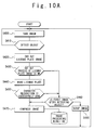
- the image taking apparatus 80 takes the image for all of the vehicles driving in the charging zone 60 (Step S400).
- object detection for checking whether or not a license plate is included in the image is performed on the image corresponding to the imaged target vehicle (Step S410).
- a cutting out process of the license plate image is performed (Step S420). If the cutting out process of the license plate is successfully executed (Step S430) and the cut out license plate is checked to be the first license plate image for the targeted vehicle, a license plate reading process of the cut license plate is successively executed (Step S440).
- Step S450 if the character recognition of the license plate is successfully executed (Step S450), and the license plate number image is recognized to be the first one for the targeted vehicle, the image is compressed to JPEG and the like (Step S430), and then stored in the image processing result DB.
- Step S430 if the cutting out process of the license plate is successfully executed (Step S430) and the cut out license plate is recognized not to be the first license plate image for the targeted vehicle, or if in the license plate reading process, the character recognition of the license plate is successfully executed (Step S450) and the license plate umber is recognized not to be the first license plate number image for the targeted vehicle (Step S460), the image is discarded (Step S480).
- the CPU 43 reads and executes the image processing program 47 preliminarily stored in the storage unit 45.
- the program is executed, as shown in Fig. 10B , a receiving process for processing various requests transmitted by the central computer system 30 is carried out (Step S500).
- the local controller 40 when receiving an image request (Step S510) transmitted by the central computer system 30 or the request for deleting image (Step S540), refers to the image processing result DB and generates a required telegraphic message.
- Step S540 When the request for deleting image (Step S540) is transmitted from the central computer system 30, from the license plate information transmitted simultaneously with it and the images stored in the image processing result DB, the image corresponding to the license plate information is searched and retrieved, and the retrieved image is removed from the image DB (Step S550). Then, a telegraphic message for deleting image to report that the image is deleted is generated (Step S560) and transmitted to the central computer system 30 (Step S570). If the license plate information is not send from the central computer system 30, the taken image, the license plate recognition result recognized from the image, the information indicating the position of imaging and the current time are transmitted to the central computer system 30, respectively.
- the image transmitted to the central computer system 30 may be compressed in order to reduce the amount of data transmission.
- Step S510 when the image send request (Step S510) is transmitted from the central computer system 30, from the license plate information transmitted simultaneously with it and the images stored in the image processing result DB, the image corresponding to the license plate information is searched and retrieved (Step S520). Then, an image data telegraphic message to report that the image is to be transmitted is generated (Step S530). Then, the image data telegraphic message, the retrieved image, the license plate recognition result recognized from the image, the imaging position information and the current time are transmitted to the central computer system 30, respectively (Step S570).
- the central computer system 30 When the central computer system 30 receives the image data, image data telegraphic message and the telegraphic message for deleting image which are respectively transmitted by the local controller 40 (Step 5300), the central computer system registers the received image data and the image data telegraphic message in the image DB and registers the telegraphic message for deleting image in the deleted image DB (Step S320), as shown in Fig. 9B .
- the local controller 40 has a timeout monitoring function. As shown in Fig. 10C , the local controller 40 checks the non-transmitted images stored in the image processing result DB at a predetermined interval (Step S600). Then, if an image that is not transmitted to the central computer system 30 even after a predetermined time is found (Step 5610), the local controller generates an image data telegraphic message (Step S620) and transmits it to the central computer system 30 (Step S630). Moreover, a plurality of local controllers 40 may be installed inside the charging zone 60. In this case, the central computer system 30 transmits license plate information through broadcast to each of the plurality of local controllers 40, so that any local controller 40 can takes images of vehicles.
- the on-vehicle transponder 50 stores in advance an on-vehicle transponder ID, geographical information and a charge table, as shown in Fig. 7 .
- the geographical information includes the charging zone indicating the geographical range that is set by the organizer as the region in which the toll is charged for the use of the road.
- the charged toll corresponding to the charging position is withdrawn by using the IC card 50a inserted in the on-vehicle transponder 50 in accordance with the charge table.
- the on-vehicle transponder 50 transmits: the charging position information indicating the position at which the vehicle enters the charging zone 60; and the transaction information (the entering time and date, the vehicle charge information 95, the electronic signature and the like) to the central computer system 30.
- the transaction information may have the format including the charging position information.
- a vehicle toll charge system and a vehicle toll charge method using the system which can be installed without large scale constructions such as a gantry for setting roadside apparatuses for obtaining information from vehicles driving in a charging zone, and the cost for constructing the system can be reduced. Also, it is possible to easily carry out the change of the charging positions where the vehicle enters the charging zone, the change of the charging amount, and the change of the registration of targeted fraudulent vehicles, only by electronically rewriting the charging position information, the charge table and the identification information of vehicles, respectively.
- a schematic configuration and operational principle of a vehicle toll charge system according to a second embodiment of the present invention are basically equal to those of the first embodiment, respectively, and their detailed descriptions are omitted.
- the on-vehicle transponder 50 judges that the on-vehicle transponder 50 enters the charging zone 60 and then transmits the charging position information and the transaction information to the central computer system 30.
- the central computer system 30 stores the charge table in advance. Then, the central computer system 30 calculates the toll charged to the vehicle entering to a charging zone based on the transaction information and charging position information which are transmitted from the on-vehicle transponder 50 and the charge table. Next, the central computer system 30 checks whether or not the charging to the vehicle 20 loading the on-vehicle transponder 50 is possible or whether or not the vehicle loading the on-vehicle transponder is a fraudulent vehicle, based on the calculated toll to be charged, the transaction information, and a pre-set vehicle identification information.
- the central computer system 30 transmits a request for deleting image, which includes the identification information of the vehicle 20 to instruct the deletion of the taken image corresponding to the vehicle 20 loading the on-vehicle transponder 50, to the local controller 40.
- the central computer system 30 transmits the image send request including the identification information of the vehicle 20 loading the on-vehicle transponder 50 to the local controller 40 for instructing the transmission of the taken image corresponding to the vehicle 20 loading the on-vehicle transponder 50 to the central computer system 30.
- a toll value data and a function of calculating a toll value are not required to be installed on the on-vehicle transponder.
- the charging amount calculated by the central computer system 30 is collected by the telecom carrier 220 and sent to the central computer system 30 held by the organizing company of the system, as shown in Fig. 11 .
- a vehicle toll charge system and a vehicle toll charge method using the system which can be installed without large scale constructions such as a gantry for setting roadside apparatuses for obtaining information from vehicles driving in a charging zone, and the cost for constructing the system can be reduced. Also, it is possible to easily carry out the change of the charging positions where the vehicle enters the charging zone, the change of the charging amount, and the change of the registration of targeted fraudulent vehicles, only by electronically rewriting the charging position information, the charge table and the identification information of vehicles, respectively.
- the schematic configuration and operational principle of a vehicle toll charge system according to a third embodiment of the present invention are basically equal to them in the first embodiment, respectively, and their detailed descriptions are omitted.
- the on-vehicle transponder 50 judges that it enters the charging zone 60, and uses a wireless communication means such as the wireless LAN and the like to directly transmit the charging position information and the transaction information to the local controller 40.
- the local controller 40 checks whether or not the charging to the vehicle 20 loading the on-vehicle transponder 50 is possible or whether or not the vehicle 20 is a fraudulent vehicle, in accordance with the charging position information and the transaction information that are transmitted by the on-vehicle transponder 50.
- the local controller 40 stores a charge table and identification information of vehicles in advance.
- the authentication computer which belongs to the central computer system 30 in a first embodiment, belongs to a local system 39 in this embodiment.
- the on-vehicle transponder 50 recognizes that it enters the charging zone 60 in accordance with the charging position information preliminarily stored in the on-vehicle transponder 50, and transmits the charging position information and the transaction information to the local controller 40.
- the local controller 40 calculates the toll charged in the charging zone 60, in accordance with the charging position information and the transaction information that are transmitted by the on-vehicle transponder 50, and the charge table.
- the local controller 40 checks whether or not the charging to the vehicle 20 loading the on-vehicle transponder 50 is possible or whether or not the vehicle loading the on-vehicle transponder 50 is a fraudulent vehicle, in accordance with the calculated charging amount and the identification information of the vehicle. If the charging to the vehicle 20 loading the on-vehicle transponder 50 is judged to be possible and if the vehicle 20 loading the on-vehicle transponder 50 is judged not to be a fraudulent vehicle, the local controller 40 deletes the obtained image corresponding to the vehicle loading the on-vehicle transponder 50 from the database, by matching the identification information of the vehicle and the license plate identification information analyzed on the basis of the image of the vehicle 20.
- the local controller 40 transmits the obtained image corresponding to the vehicle loading the on-vehicle transponder 50 to the central computer system 30 by matching the identification information of the vehicle and the license plate identification information,
- a vehicle toll charge system and a vehicle toll charge method using the system which can be installed without large scale constructions such as a gantry for setting roadside apparatuses for obtaining information from vehicles driving in a charging zone, and the cost for constructing the system can be reduced. Also, it is possible to easily carry out the change of the charging positions where the vehicle enters the charging zone, the change of the charging amount, and the change of the registration of targeted fraudulent vehicles, only by electronically rewriting the charging position information, the charge table and the identification information of vehicles, respectively.
- the on-vehicle transponder 50 transmits the charging position information and the transaction information to the local controller 40, by using a wireless communication unit such as the wireless LAN and the like, communication costs can be reduced compared with a communication using a data line of a telecom carrier.
- a "distance based charging type" vehicle toll charge system for setting the charging amount on the basis of the driving distance in the zone of the vehicle 20 entering a charging zone 60 is applied to any one of vehicle toll charge systems described in first to third embodiments.
- the schematic configuration and operational principle of the vehicle toll charge system according to this embodiment are basically equal to any of first to third embodiments, respectively.
- the local controllers 40 are installed at an exit A and an exit B of the charging zone 60, respectively.
- the on-vehicle transponder 50 stores the total distance of a vehicle 20 inside the region of a charging zone 60, in accordance with the charging position information corresponding to the position where the vehicle 20 enters the charging zone 60 and the charging position information corresponding to the position where the vehicle 20 exits from the charging zone. For example, in the case of the application to a second embodiment, when judging that a vehicle 20 exits from a charging zone 60, the on-vehicle transponder 50 transmits the transaction information and the total distance information inside the charging zone to the central computer system 30. The central computer system 30 calculates the charging amount, in accordance with the received transaction information, the total distance information inside the charging zone, and the charge table corresponding to the distance based charging.
- a vehicle toll charge system and a vehicle toll charge method using it which can be installed without large scale constructions such as a gantry for setting roadside apparatuses for obtaining information from vehicles driving in a charging zone, and the cost for constructing the system can be reduced. Also, it is possible to easily carry out the change of the charging positions where the vehicle enters the charging zone, the change of the charging amount, and the change of the registration of targeted fraudulent vehicles, only by electronically rewriting the charging position information, the charge table and the identification information of vehicles, respectively. Also, not only a constant toll charging, it is possible to carry out a charging setting based on the driving distance of a vehicle inside the charging zone 60.
- the vehicle toll charge system judges whether or not the charging is normally executed by using the image of the license plate taken by the local controller 40 in any one of vehicle toll charge systems described in first to fourth embodiments.
- the schematic configuration and operational principle of the vehicle toll charge system according to this embodiment are basically equal to those of first to third embodiments, respectively. Here, only the points different from other embodiments are described.
- the vehicle toll charge system in this embodiment includes the local side systems 39.
- the local side systems 39 are installed at all exits 60out of the charging zone 60, namely, all positions where the vehicle 20 can exit from the charging zone 60.
- the local system 39 includes: a camera 79 whose field of view includes the exit 60out that is a position where vehicles 20 exit from the charging zone 60; and a communication unit 81 for transmitting the image taken by the camera 7 9 to the central computer system 30.
- a vehicle 20 enters the charging zone 60.
- the on-vehicle transponder 50 generates the position information indicating its position, in accordance with the GPS information 15 received from GPS satellites 10.
- the on-vehicle transponder 50 performs matching of the geographical position relation between its position and the charging zone, in accordance with the charging zone information that is the geographical information indicating the charging zone 60 (refer to Fig. 7 ) and the position information, and consequently recognizes that the vehicle 20 enters the charging zone 60.
- the on-vehicle transponder 50 when recognizing that the vehicle 20 driving in a charging zone 60 arrives at a boundary between the charging zone 60 and its outside and is located at the exit 60out of the charging zone 60, transmits transaction information, which includes the on-vehicle transponder ID and the card ID serving as the identifier of the card inserted in the on-vehicle transponder 50, to the central computer system 30 by using a mobile communication technique.
- the central computer system 30 stores the received transaction information.
- the central computer system 30 stores the information indicating the time when the transaction information is received as a transaction information reception time (refer to Fig. 5 (2) #1).
- the local system 39 generates all vehicle image in which all of the vehicles 20 exiting from the exits 60 out of the charging zone 60 are imaged at the place where the camera 79 is installed.
- the all vehicle image is a video image that is continuously taken and whose field of view includes the exits 60out.
- the communication unit 81 transmits the local system information, which includes the all vehicle image, the imaging time and a local system ID (the local system ID is, for example, the information of the latitude and the longitude) to specify the position of the local system 39, to the central computer system 30 continuously in real time.
- the central computer system 30 stores the received local side system information (refer to Fig. 5 (5) #2) .
- the central computer system 30 stores a license plate database in which the on-vehicle transponder ID and the license plate (accurately, the symbols on the license plate (including numerals, characters and the like)) are linked.
- the central computer system 30 retrieves the license plate corresponding to the on-vehicle transponder ID included in the received transaction information from the license plate database and generates on-vehicle transponder side license plate information that is the set of the retrieved license plate and the transaction information reception time.
- the central computer system 30 performs an image recognition on the all vehicle image included in the local system information, reads the symbols on the license plate and generates the camera side license plate information, which is the set of the license plates of all the vehicles 20 exiting from the exits 60out of the charging zone 60 and the imaging time.
- the central computer system 30 executes a license plate matching process for matching the on-vehicle transponder side license plate information and the camera side license plate information.
- a license plate matching process for matching the on-vehicle transponder side license plate information and the camera side license plate information.
- the authentication is judged to be failed.
- the on-vehicle transponder 50 when the lack of remaining amount of a card, the non-insertion of a card, or a communication error disables the normal charging, the on-vehicle transponder 50 adds a status of the charging error to the transaction information and transmits it to the central computer system 30.
- the central computer system 30 recognizes that the charging is not normally executed, if the status of the charging error is added to the transaction information, even if the matching of the license plate is successfully done.
- the central computer system 30 recognizes that the charging is not normally executed, similarly to the case that the status of the charging error is added.
- a vehicle 20a does not load the on-vehicle transponder 50.
- the local system 39 transmits the local side system information to the central computer system 30, independently of the presence or absence of the on-vehicle transponder 50.
- the central computer system 30 generates the camera side license plate information from the received local side system information.
- the central computer system 30 executes the license plate matching process. In this process, the on-vehicle transponder side license plate information which coincides with the camera side license plate information is retrieved. However, since the vehicle 20a does not load the on-vehicle transponder 50, the retrieval of the coincident on-vehicle transponder side license plate information is failed. In this case, the central computer system 30 recognizes that the authentication is not successfully done and the charging is not normally executed, and then stores the camera side license plate information as a non-communicable license plate data.
- the image recognition of the license plate is carried out on the central computer system 30 side.
- the local side system can be simply constituted.
- the central computer system 30 can recognize the image information from the camera 79 in accordance with the license plate information obtained by converting the on-vehicle transponder ID.
- the recognizing process can be performed based on whole of the plurality of characters on the license plate. As a result, the recognition rate is extremely improved.
- Vehicle Toll Charge System for Recognizing Vehicle ID in Local Side System
- a vehicle toll charge system In a vehicle toll charge system according to a sixth embodiment, the function of the central computer system 30 for applying image recognition to a license plate and converting it into an on-vehicle transponder ID in a fifth embodiment is moved to the local system 39.
- the vehicle toll charge system in this embodiment will be described below with reference to Fig. 14 .
- the local system 39 which has a configuration different to that of a fifth embodiment is installed at an exit of a charging zone 60 in this embodiment.
- the license plate image taking apparatus 80 contains a camera 79, a vehicle registration identifier recognizer 39-1, a vehicle ID converter 39-2 and a database 39-3.
- the camera 79 is installed at the same position as the camera 79 in Fig. 13 .
- the camera 79 generates an image of all of the vehicles 20 which exit from the charging zone 60, and the exiting position information indicating the latitudes and longitudes at that time, and the exiting time.
- the vehicle registration identifier recognizer 39-1 executes image recognition to the image. Then, the symbols on the license plates represented in the image are read and extracted as the license plate information.
- the database 39-3 stores a license plate (accurately, the symbols on the license plate (including the numerals, characters and the like)) and the vehicle ID used for the vehicle toll charge system to specify the registered vehicle linked to each other.
- the vehicle ID converter 39-2 refers to the database 39-3, retrieves the vehicle ID corresponding to the license plate information retrieved by the vehicle registration identifier recognizer 39-1 and generates the local side vehicle ID information that is the set of the exiting position information, the exiting time and the retrieved vehicle ID, and then transmits it to the central computer system 30.
- the on-vehicle transponder 50 transmits the transaction information to the central computer system 30, at the time of the exiting from the charging zone 60, similarly to a fifth embodiment.
- the central computer system 30 uses the on-vehicle transponder ID included in the transaction information, as an on-vehicle transponder side vehicle ID serving as an identifier to specify a vehicle 50 in the vehicle toll charge system.
- the central computer system 30 generates the on-vehicle transponder side vehicle ID information that is the set of the on-vehicle transponder side vehicle ID included in the transaction information and the reception time.
- the central computer system 30 executes matching of the on-vehicle transponder side vehicle ID information and the local side vehicle ID information to consequently execute the authentication of the vehicle 20.
- a vehicle toll charge system In a vehicle toll charge system according to a seventh embodiment, the function of the central computer system 30 for applying image recognition to a license plate in a vehicle toll charge system in a fifth embodiment is moved to the local system 39.
- the license plate image taking apparatus 80 is installed at an exit of the charging zone 60 in this embodiment.
- the license plate image taking apparatus 80 includes a camera 79 and a vehicle registration identifier recognizer 39-1.
- the camera 79 is installed at the same position as the camera 79 in Fig. 13 .
- the camera 79 generates an image of all of the vehicles 20 which exit from the charging zone 60, and the exiting position information indicating the latitudes and longitudes at that time, and the exiting time.
- the vehicle registration identifier recognizer 39-1 executes image recognition to the image. Then, the symbols on the license plates represented in the image are read and extracted as the license plate information.
- the vehicle registration identifier recognizer 39-1 generates the camera side license plate information which is the set of the license plate information, exiting position information and the exiting time and transmits it to the central computer system 30.
- the central computer system 30 stores the license plate database, in which a license plate (accurately, the symbols on the license plate (including the numerals, characters and the like)) and the vehicle ID used for the vehicle toll charge system to specify the registered vehicle are linked to each other.
- the on-vehicle transponder 50 transmits the transaction information to the central computer system 30, at the time of the exiting from the charging zone 60, similarly to a fifth embodiment.
- the central computer system 30 uses the on-vehicle transponder ID included in the transaction information, as the on-vehicle transponder side vehicle ID serving as an identifier to specify the vehicle 50 in the vehicle toll charge system.
- the central computer system 30 generates the on-vehicle transponder side vehicle ID information that is the set of the on-vehicle transponder side vehicle ID included in the transaction information and the reception time.
- the central computer system 30 refers to the license plate database, converts the license plate, which is included in the local side license plate information, into the vehicle ID, and then executes matching of the vehicle ID and the vehicle ID (on-vehicle transponder ID) included in the on-vehicle transponder side vehicle ID information to consequently execute the authentication of the vehicle 50.
- the license plate information is recognized on the camera side (local side) and transmitted to the central computer system 30.
- the information communication amount is extremely small, and the establishment of the communication network is easy.
- the local side stores a database in which the license plate and the vehicle ID are linked to convert the license plate into the vehicle ID.
- the configuration of the local side is simple, so that the construction cost of the local side can be reduced.
- the information obtained through the wireless communication from the on-vehicle transponder 50 and the image information in which the vehicle is imaged are used for the vehicle existing in the charging zone 60.
- the camera side system which includes, for example, a lot of local controllers 40 installed in the charging zone to use accurate time information.
- the vehicle toll charge system in this embodiment includes a GPS receiver 30a connected to the central computer system 30a, in addition to the configuration shown, in first to seventh embodiments.
- the central computer system 30a receives the GPS information, which is transmitted by the GPS satellites, through the GPS receiver 30a and obtains the GPS time that is the information indicating the accurate time at the time of the reception of the GPS information.
- the central computer system 30a distributes the GPS time to all of the local side systems installed in the charging zone 60, namely, the local controllers 40, the license plate image taking apparatuses 80 and the like.
- the local side system generates the image information to which the time adjusted in accordance with the received GPS time is added, for the image of the vehicle 20.
- the local side system transmits the image of the vehicle 20, the information of the license plate read from the image or the information obtained by converting the license plate information into the corresponding vehicle ID, together with the time, in accordance with the image information to which the time is added, to the central computer system 30.
- the on-vehicle transponder 50 uses the GPS function to obtains the GPS time and transmits it together with the position information to the central computer system 30.
- the central computer system 30 can accurately execute the authentication of the charging, because both of the information received from the on-vehicle transponder 50 and the information received from the local side system are synchronous through the GPS time. According to such a vehicle toll charge system, the large scale of the synchronized system can be easily established.
- GPS receivers 78-1 to 78-N are installed in each of many local side systems (cameras 79-1 to 79-N) that are installed in the charging zone 60, respectively.
- the GPS receives 78-1 to 78-N generate the position information and the GPS time, in accordance with the GPS signal received from the GPS satellites 10, and adds them to the information obtained by imaging the vehicle and then transmits it to the central computer system 30.
- the large scale synchronization system can be easily established similarly to an eighth embodiment. Moreover, since the local side system can obtain the position information by using the GPS function, the positions of the local side systems are not required to be independently inputted to the database for managing the positions.
- the authentication is carried out at the exit of the charging zone 60. In a tenth embodiment, the authentication is carried out at the entrance of the charging zone 60.
- the local system 39 is installed around an entrance of the charging zone 60, and the license plate image taking apparatus 80 takes an image of a vehicle 50 that enters the charging zone 60 from outside the charging zone 60, and applies image recognition to the image to read the license plate, and then transmits it together with the position and current time of the local system 39 through the communication unit 81 to the central computer system 30.
- the on-vehicle transponder 50 when moving into the charging zone 60 at a charging zone entrance 60in from outside the charging zone 60, executes a settlement process for using the card inserted in the on-vehicle transponder 50 and withdrawing the charged toll and then transmits the position information of the charging zone entrance 60in, the time and the on-vehicle transponder ID to the central computer system 30.
- the central computer system 30 executes matching of the information received from the local system 39 and the information received from the on-vehicle transponder 50 to consequently execute the authentication of the vehicle 50.
- a vehicle 50a that does not load the on-vehicle transponder 50 is recognized to be a fraudulent vehicle in the central computer system 30, because the on-vehicle transponder ID matched with the license plate obtained from the license plate image taking apparatus 80 is not transmitted thereto.
- a fraudulent vehicle can be specified at the entrance of the charging zone 60.
- a fraudulent vehicle can be specified at the entrance of the charging zone 60.
- the information indicating that the on-vehicle transponder 50 is normally charged to outside the vehicle it is possible to visibly judge a fraudulent vehicle inside the charging zone 60.
- a displaying lamp on the roof of a vehicle registered in the vehicle toll charge system if the charging process is normally executed, such a judgment can be carried out by turning on and off the displaying lamp in a particular pattern.
- a monitoring person can easily check a fraudulent vehicle. Further, there is an effect for drivers to suppress fraudulence.
- the local side system in a ninth embodiment is installed. Then, together with the entrance side of the charging zone 60, also on the exit side, the information from the on-vehicle transponder 50 and the information from the local side system are transmitted to the central computer system 30. Then, the position information and time information of the entrance side and the position information and exit information of the exit side are used to calculate the charged toll.
- the charging is not carried out at the charging zone entrance 60in. Then, only the information indicating that the vehicle is registered as the vehicle using the vehicle toll charge system is transmitted from the on-vehicle transponder 50 to the central computer system 30. The charging is carried out at the charging zone exit 60out.
Abstract
Description
- The present invention relates to a vehicle toll charge system, and a vehicle toll charge method using it, and more particularly relates to a vehicle toll charge system and a vehicle toll charge method using it for reducing a construction cost.
- In conventional vehicle toll charge systems, represented by the ERP (Electric Road Pricing) systems implemented in Singapore, it is required to install apparatuses such as a vehicle sensor for obtaining vehicle information of vehicles driving in a charging area, and a wireless communication apparatus for the DSRC (Dedicated Short Range Communication) in large scale constructions represented by the gantry. The cost of constructing such a vehicle toll charge system is high, and the reduction of the construction cost is strongly desired.
- In relation to foregoing techniques, following reports are known.
- In "An Apparatus for Vehicle Charging Processing" disclosed in Japanese Patent No.
3365296 - Also, in "Charging Apparatus and System" disclosed in Japanese Patent No.
3353683 - An object of the present invention is to provide a vehicle toll charge system and a vehicle toll charge method using it, which can be installed without large scale constructions such as a gantry for setting roadside apparatuses for obtaining information from vehicles driving in a charging zone, and the cost for constructing the system can be reduced.
- According to an aspect of the present invention, a vehicle toll charge system includes: an on-vehicle transponder configured to be loaded on a vehicle, have a GPS (Global Positioning System) function, and storing a charging zone information indicating a charging zone where a toll is charged and an on-vehicle transponder identification information being assigned to individually identify the on-vehicle transponder; a local computer system configured to generate an image data by taking an image of a vehicle existing in the charging zone; a central computer system configured to be connected to the local computer system via a wide area network and receive the image data; and an authentication computer configured to store identification information of a preliminary registered vehicle. The on-vehicle transponder transmits the on-vehicle transponder identification information to the authentication computer at a predetermined timing when recognizes being in the charging zone based on a position information obtained by the GPS function. The authentication computer executes an authentication for charging a toll on a vehicle based on a matching result of the on-vehicle transponder identification information received from the on-vehicle transponder and the identification information of the preliminary registered vehicle.
- According to another aspect of the present invention, in a vehicle toll charge system, the authentication computer is included in the central computer system.
- According to yet another aspect of the present invention, in a vehicle toll charge system, the authentication computer, when the authentication is failed, transmits information corresponding to the on-vehicle transponder identification information of a vehicle the authentication thereof is failed to the local computer system. The local computer system transmits the image data of a vehicle the authentication thereof is failed to the central computer system, in accordance with a matching of information corresponding to the received on-vehicle transponder identification information and an imaged license plate of a vehicle.
- According to yet another aspect of the present invention, in a vehicle toll charge system, the authentication computer is configured to judge whether or not a vehicle loading the on-vehicle transponder is a fraudulent vehicle by executing matching of the on-vehicle transponder identification information and a preliminary registered fraudulent vehicle identification information, and if a vehicle loading the on-vehicle transponder is judged as a fraudulent vehicle, the authentication computer transmits information corresponding to the on-vehicle transponder identification information of a vehicle which is judges as a fraudulent vehicle. The local computer system transmits the image data of a vehicle which is judged as a fraudulent vehicle to the central computer system by executing matching of the received information corresponding to the on-vehicle transponder identification information and an imaged license plate of a vehicle.
- According to yet another aspect of the present invention, in a vehicle toll charge system, a card which stores a money amount or a value corresponding to the money amount is inserted in the on-vehicle transponder. The on-vehicle transponder is configured to calculate a charging amount charged in the charging zone based on the position information and a preliminary stored charge table and generate transaction information which includes information indicating a value generated by subtracting the charging amount from the money amount or a value corresponding to the money amount and transmit the transaction information to the authentication computer.
- According to yet another aspect of the present invention, in a vehicle toll charge system, the authentication computer stores a charge table, and configured to: calculate a charging amount charged in the charging zone based on the position information received from the on-vehicle transponder and the charge table; and judge whether charging on a vehicle loading the on-vehicle transponder is possible or not based on the charging amount and the identification information of a vehicle. When the charging on a vehicle is judged to be impossible, the authentication computer transmits an image send request, which includes the identification information of a vehicle, for requesting the local computer system to transmit the image data corresponding to a vehicle loading the on-vehicle transponder to the central computer system.
- According to yet another aspect of the present invention, in a vehicle toll charge system, the authentication computer is included in the local computer system. The local computer system is configured to: calculate a charging amount charged in the charging zone based on the position information received from the on-vehicle transponder and the charge table; and judge whether charging on a vehicle loading the on-vehicle transponder is possible or not based on the charging amount and the identification information of a vehicle; and when the charging on a vehicle is judged to be impossible, the local computer system transmits the image data corresponding to a vehicle loading the on-vehicle transponder to the central computer system, by executing a matching of the identification information of a vehicle loading the on-vehicle transponder and an obtained license plate identification information.
- According to yet another aspect of the present invention, in a vehicle toll charge system, the local computer system is installed in a position from which an image of a vehicle existing at an exit of the charging zone is taken. The charging amount is calculated by using the charge table based on the position information corresponding to a position where a vehicle enters the charging zone and the position information corresponding to a position where a vehicle exits the charging zone.
- According to yet another aspect of the present invention, in a vehicle toll charge system, any of the charging zone, the charge table and the identification information of a vehicle stored in the on-vehicle transponder can be rewritten by an input operation to the central computer system.
- According to yet another aspect of the present invention, in a vehicle toll charge system, the authentication computer is included in the central computer system. The image data includes an image of every vehicle passes a predetermined area and a stamped time. The authentication computer executes the authentication based on judging whether or not a vehicle whose image is taken by the local computer system is preliminary registered. The judging is executed based on an execution of matching of a license plate preliminary registered correspondingly to the identification information of a vehicle and information of a license plate included in the image data.
- According to yet another aspect of the present invention, in a vehicle toll charge system, the local computer system is installed in a position from where an image of a vehicle existing at an exit of the charging zone is taken.
- According to yet another aspect of the present invention, in a vehicle toll charge system, the authentication computer is configured to store information of a license plate of a vehicle extracted from the image of every vehicle as a communication incapable license plate data, when a license plate corresponding to the on-vehicle transponder identification information received from the on-vehicle transponder does not exist in the image of every vehicle.
- According to yet another aspect of the present invention, in a vehicle toll charge system, the authentication computer is included in the central computer system. The local computer system stores a registered vehicle table in which a vehicle identifier for identifying a preliminary registered vehicle and a license plate is linked. The local computer system is configured to extract the vehicle identifier corresponding to a license plate included in the image of every vehicle, and add the extracted vehicle identifier to the image data. The authentication computer is configured to execute the authentication based on matching of the vehicle identifier received from the on-vehicle transponder and the identification information of the preliminary registered vehicle.
- According to yet another aspect of the present invention, in a vehicle toll charge system, the authentication computer is included in the central computer system. The local computer system is configured to read a character on a license plate in the image of every vehicle by an image recognition and add the character to the image data. The authentication computer is configured to execute the authentication by using the character included in the received image data as the information of the license plate included in the image data.
- According to yet another aspect of the present invention, in a vehicle toll charge system, the local computer system is installed in a position adoptive to take an image of a vehicle existing in an entrance of the charging zone.
- According to an aspect of the present invention, a vehicle toll charge method includes: an on-vehicle transponder recognizing that the on-vehicle transponder enters a charging zone where a toll is charged based on a position information obtained by using GPS function, wherein the on-vehicle transponder is loaded on a vehicle and stores the charging zone and an on-vehicle transponder identification information being assigned to identify the on-vehicle transponder; a local computer system generating image data by taking vehicle image being an image of a vehicle in the charging zone; a central computer system receiving the vehicle image from the local computer system; extracting and storing information of a license plate from the vehicle image; the on-vehicle transponder transmitting transaction information including the on-vehicle transponder identification information to an authentication computer via a wireless communication in a predetermined timing when the on-vehicle transponder enters the charging zone; and the authentication computer executing an authentication for charging a toll on a vehicle loading the on-vehicle transponder based on the on-vehicle transponder identification information received from the on-vehicle transponder and preliminary registered identification information of a vehicle.
- According to an aspect of the present invention, a vehicle charge program according to the present invention instructs a computer to execute the vehicle toll charge method according to the present invention.
- According to the present invention, it is possible to provide a vehicle toll charge system and a vehicle toll charge method using it, which can be installed without large scale constructions such as a gantry for setting roadside apparatuses for obtaining information from vehicles driving in a charging zone, and the cost for constructing the system can be reduced.
- Moreover, according to the present invention, it is possible to easily carry out changes of charging positions, charging amounts, and registered target fraudulent vehicles, only by electronically rewriting the charging position information, the charge table and the identification information of the vehicles, respectively.
-
-
Fig. 1 is a schematic view showing a configuration of a vehicle toll charge system according to an embodiment of the present invention; -
Fig. 2 is a schematic view showing a configuration of a central computer system included in a vehicle toll charge system according to an embodiment; -
Fig. 3 is a schematic view showing a configuration of a local controller included in a vehicle toll charge system according to an embodiment; -
Fig. 4 is a schematic view showing a configuration of an on-vehicle transponder included in a vehicle toll charge system according to an embodiment; -
Fig. 5 is a data list stored in a database section of the central computer system; -
Fig. 6 is a data list stored in a database section of the local controller; -
Fig. 7 is a data list stored in a database section of the on-vehicle transponder; -
Fig. 8 is a view showing a data flow in a vehicle toll charge system according to a first embodiment; -
Fig. 9A is a view showing a processing flow of the central computer system in a vehicle toll charge system according to a first embodiment; -
Fig. 9B is a view showing a processing flow of the central computer system in a vehicle toll charge system according to a first embodiment; -
Fig. 10A is a view showing a processing flow of a local controller in a vehicle toll charge system according to a first embodiment; -
Fig. 10B is a view showing a processing flow of a local controller in a vehicle toll charge system according to a first embodiment; -
Fig. 10C is a view showing a processing flow of a local controller in a vehicle toll charge system according to a first embodiment; -
Fig, 11 is a view showing a data flow in a vehicle toll charge system according to a second embodiment; -
Fig. 12 is a schematic view showing a configuration of a vehicle toll charge system according to a fourth embodiment; -
Fig. 13 is schematic view showing a configuration of a vehicle toll charge system according to a fifth embodiment; -
Fig. 14 is a schematic view showing a configuration of a vehicle toll charge system according to a sixth embodiment; -
Fig. 15 is a schematic view showing a configuration of a vehicle toll charge system according to a seventh embodiment; -
Fig. 16 is a schematic view showing a configuration of a vehicle toll charge system according to an eighth embodiment; -
Fig. 17 is a schematic view showing a configuration of a vehicle toll charge system according to a ninth embodiment; and -
Fig. 18 is a schematic view showing a configuration of a vehicle toll charge system according to a tenth embodiment. - Best mode for carrying out the vehicle toll charge system and the vehicle toll charge method using it will be described below with reference to the attached drawings.
- A vehicle toll charge system according to the present invention includes: an on-vehicle transponder having the GPS function and is installed in a vehicle such as an automobile or the like; a local controller which is installed at a specific position in a charging zone in which a payment of a toll is required and includes an image taking apparatus for taking images of vehicles; and a central computer system which is installed at arbitrary position and preliminary stores identification information such as license plate information of vehicle and the like.
- When a vehicle enters a charging zone, the on-vehicle transponder recognizes that the vehicle entered the charging zone, in accordance with the charging position information preliminarily stored in the on-vehicle transponder. Then, the on-vehicle transponder transmits charging position information indicating the position at which the vehicle entered the charging zone and the transaction information (the entering time and date, the charged toll, the electronic signature and the like) to the central computer system. The transaction information may include the charging position information. The central computer system checks the charging position information and the transaction information, which are transmitted from the on-vehicle transponder, and the preliminary stored identification information of the vehicle to check at least one of: whether or not the toll can be charged on the vehicle loading the on-vehicle transponder; and whether or not the vehicle loading the on-vehicle transponder is registered as a fraudulent vehicle. As a result of the check, if the central computer system judges that the charging on the vehicle loading the on-vehicle transponder is possible and the vehicle loading the on-vehicle transponder is not a fraudulent vehicle, the central computer system transmits a request for deleting image, which instructs the deletion of the obtained image corresponding to the vehicle loading the on-vehicle transponder, to the local controller. This request for deleting image includes the identification information of the target vehicle. As a result of the check, if the central computer system judges that the charging on the vehicle loading the on-vehicle transponder is impossible or the vehicle loading the on-vehicle transponder is a fraudulent vehicle, the central computer system transmits an image send request, which instructs the sending of the obtained image corresponding to the vehicle loading the on-vehicle transponder to the central computer system, to the local controller. This image send request also includes the identification information of the vehicle. On the other hand, the local controller takes images and stores the images of the license plates of every vehicle loading the on-vehicle transponder in the charging zone by using the image taking apparatus. The local controller analyzes (executes an optical character recognition process on) the license plate information of the vehicles, in accordance with the license plate image of the imaged vehicles and obtains the analyzed license plate information as the license plate identification information. The local controller, when receiving the request for deleting image from the central computer system, checks the matching of the identification information of the vehicle transmitted from the central computer system and the aforementioned license plate identification information to delete the license plate image of the vehicle corresponding to the request for deleting image. Also, when receiving the image send request from the central computer system, the local controller checks the matching of the identification information of the vehicle transmitted from the central computer system and the aforementioned license plate identification information to send the license plate image of the vehicle corresponding to the image send request, to the central computer system.
- According to an embodiment of the present invention, it is possible to provide a vehicle toll charge system and a vehicle toll charge method using it, which can be installed without large scale constructions such as a gantry for setting roadside apparatuses for obtaining information from vehicles driving in a charging zone, and the cost for constructing the system can be reduced.
-
Fig. 1 shows a schematic configuration of the vehicle toll charge system according to a first embodiment of the present invention. The vehicle toll charge system according to this embodiment is, in particular, a vehicle toll charge system of the type in which the charged toll corresponding to the driving charging zone is subtracted from the amount indicated in a card inserted in the on-vehicle transponder. - A vehicle
toll charge system 100 according to this embodiment includes: an on-vehicle transponder 50 which is installed in avehicle 20 such as an automobile and the like and has a function for receiving aGPS information 15 transmitted by aGPS satellite 10;local controllers 40 which are installed at specific positions inside a chargingzone 60 in which the payment of the toll is required and has license plateimage taking apparatuses 80 for taking images of thevehicles 20; and acentral computer system 30 that is installed at arbitrary position and stores in advance the identification information such as the license plate information of thevehicle 20 and the like. -
Fig. 2 shows a schematic configuration of thecentral computer system 30. Thecentral computer system 30 includes aCPU 33, astorage unit 36, aninput unit 35 for inputting new information, rewriting stored data and an instruction; acommunication unit 32 for communing with the on-vehicle transponder 50 and thelocal controller 40; and anantenna unit 34, which are connected to a bus line 31, respectively. Thestorage unit 36 stores in advance adatabase section 38 for storing a plurality of data as shown inFig. 5 (vehicle information to specify a fraudulent vehicle, a transaction, image data and an image deletion record) and avehicle charge program 37 for operating thecentral computer system 30. The functions of thecentral computer system 30 will be schematically described below. - The central computer system receives the transaction and
vehicle charge information 95 transmitted by the on-vehicle transponder 50. - The central computer system checks the transaction transmitted by the on-
vehicle transponder 50 to judge whether or not the toll is normally charged and whether or not an error is detected by the on-vehicle transponder 50. The result of the judgment and the data included in the transaction are recorded in the transaction database stored in thedatabase section 38 of thestorage unit 36. If the transaction transmitted by the on-vehicle transponder 50 is judged to be normal, the license plate information of that vehicle together with the request for deleting image is transmitted to thelocal controller 40. On the other hand, if the transaction is judged to be fraudulent or erroneous, an image send request telegraphic message is transmitted to thelocal controller 40. - The central computer system performs the management of the following databases preliminarily stored in the
database section 38 in thestorage unit 36. - The transaction transmitted by the on-
vehicle transponder 50 and its evaluation result are stored. - A stolen vehicle, a violator vehicle, a vehicle on which the charge is erroneously ended, and the like are registered in the fraudulent vehicle database. When the vehicle registered in the fraudulent vehicle database is recognized by the
local controller 40, its image is transmitted to thecentral computer system 30. - The image, which is obtained by the
local controller 40 and transmitted to thecentral computer system 30, is stored together with the license plate recognition result in the database. - The central computer system requests for deleting image to the
local controller 40. When the result of the deletion of the image is received, the central computer system stores the telegraphic message in the deleted image database. - Through the communication with the
local controller 40, the central computer system transmits to and receives from the telegraphic messages shown below. -
- Image Data (Including License plate Reading Result)
- Result of Deleting Image
-
- Image send request
- Request for deleting image
-
Fig. 3 shows a schematic configuration of thelocal controller 40. Thelocal controller 40 includes aCPU 43, astorage unit 45, acommunication unit 42 for communicating with the on-vehicle transponder 50 or thecentral computer system 30, and anantenna unit 44, which are connected to a bus line 41, respectively. Thestorage unit 45 stores in advance adatabase section 46 for storing a plurality of data as shown inFig. 6 (a position ID, an image, an image send request and a request for deleting image) and animage processing program 47 for operating thelocal controller 40. Also, the license plateimage taking apparatus 80 for taking an image of the license plate of avehicle 20 driving in the chargingzone 60 is connected through thecommunication unit 42. The functions of thelocal controller 40 will be schematically described below. - A camera (license plate image taking apparatus 80) that can continuously take images is used to take images of a vehicle that enters the visual field of the camera. The imaging is carried out at a speed of about 30 frames per second, and the cutting out process of the license plate image is carried out for each frame, and the reading process of the license plate is performed on the image in which a license plate is found out.
- The process of reading the license plate is performed on the image in which a license plate is found out, and the reading result is recorded. An image data reading process is finished is compressed by using JPEG and the like.
- The following telegraphic messages are transmitted to and received from the
central computer system 30. -
- Image send request
- Request for deleting image
-
- Image + License plate Recognition Result
- Image deletion record + License plate Recognition Result
- After an image is taken, when both of the image send request and the request for deleting image cannot be received from the
central computer system 30 within a preset time, the local controller transmits compressed image information and license plate recognition result to thecentral computer system 30. -
Fig. 4 shows a schematic configuration of the on-vehicle transponder 50. The on-vehicle transponder 50 includes aCPU 53, astorage unit 55, acommunication unit 52 for receivingGPS information 15 and carrying out the communication between thelocal controller 40 and thecentral computer system 30, and anantenna 54, which are connected to a bus line 51, respectively. Thestorage unit 55 stores in advance a plurality of data as shown inFig. 7 (an on-vehicle transponder ID, charging position information and a charge table) and atoll processing program 57 for operating the on-vehicle transponder 50. The schematic functions of the on-vehicle transponder 50 will be described below. - The on-vehicle transponder ID is registered on the on-vehicle transponder before the on-
vehicle transponder 50 is installed on the automobile (vehicle 20). The on-vehicle transponder holds the on-vehicle transponder ID. - The on-vehicle transponder judges whether or not the position obtained by the GPS position measuring enters a charging zone. If the vehicle loading the on-vehicle transponder is judged to enter a charging zone, the on-vehicle transponder carries out a charging process.
- Charging Process:
- In the case of a card charging, the charged toll is withdrawn by using the card, and its result is transmitted to the central computer system (this corresponds to the vehicle toll charge system according to a first embodiment of the present invention).
- In the case of a central style (wherein a card is not used), the transaction and the charging position information which are based on the judgment of the entering to the zone are transmitted to the central computer system (this corresponds to the vehicle toll charge system, according to a second embodiment of the present invention).
- By referring to the charge table corresponding to the charging zone, the charged toll is calculated.
- The on-vehicle transponder transmits the charging process result to the
central computer system 30. Further, the on-vehicle transponder receives the charge table and update data with regard to the charging position information from the central computer system to performing update process. As a communication means of the on-vehicle transponder, mobile communication techniques are used. On the communication data, the process based on encryption techniques are applied for preventing leak and tampering of the data. - The on-vehicle transponder receives information with regard to the charge table and the charging zone from the
central computer system 30, and the data inside the on-vehicle transponder 50 is updated. - The vehicle
toll charge system 100 according to this embodiment will be described below with reference toFig. 8 to Fig. 10C . The automobile (vehicle 20) in this embodiment includes an on-vehicle transponder 50 having the positioning function in which the GPS is used. AnIC card 50a to which a value indicating the amount of the money or a value corresponding to it is recorded is inserted into the on-vehicle transponder 50. When the vehicletoll charge system 100 is started up, theCPU 53 of the on-vehicle transponder 50 reads thetoll processing program 57 preliminarily stored in thestorage unit 55 and executes it. When the program is executed, the on-vehicle transponder 50 withdraws the charged toll from theIC card 50a when the vehicle loading it is judged to arrive at the chargingzone 60 preliminarily registered in the on-vehicle transponder 50. The charged toll is assumed to be preliminarily stored as the charge table in the on-vehicle transponder 50 or calculated by the on-vehicle transponder 50 at the time of charging. The charging result is wirelessly transmitted to thecentral computer system 30 from the on-vehicle transponder 50 by using the mobile communication function managed by atelecom carrier 220, as illustrated in adataflow 200 of the vehicle toll charge system shown inFig. 8 . At this time, the position information to identify the charging zone in which the charging process is executed is simultaneously transmitted to thecentral computer system 30. - In the
central computer system 30, the authentication computer belonging to thecentral computer system 30 executes the authentication process for thevehicle 20, as follows. When the vehicletoll charge system 100 is started up, theCPU 33 reads and thevehicle charge program 37 preliminarily stored in thestorage unit 36 and executes it. When the program is executed, a transaction receiving process for classifying the information included in the received transaction is carried out, in accordance with the reception of the transaction including the charging result from the on-vehicle transponder 50 (Step S200), as illustrated in the processing flow of the central computer system inFig. 9A (Step S210). Then, the central computer system performs matching of the vehicle identification information transmitted by the on-vehicle transponder 50 and the fraudulent vehicle DB which is preliminarily registered therein and stores the vehicle identification information of fraudulent vehicles to execute a database search for checking whether or not the vehicle loading the on-vehicle transponder 50 is a fraudulent vehicle (Step S220). Next, the central computer system judge whether or not the charging is normally executed in a transaction evaluating process, based on the user registration registered by adriver 230, for the usage history and electronic signature that are transmitted by the on-vehicle transponder 50. The usage history and electronic signature that are processed in thecentral computer system 30 are transmitted to acard issuer 210. Then, when thecard issuer 210 admits the settlement, the money amount is withdrawn from the account of thedriver 242 of thebank 240 or the like that is opened by the driver. Then, thecard issuer 210 remits the money corresponding to the toll of the chargingzone 60 to thecentral computer system 30 through the account of thecard issuer 241. When the series of the processes is completed, thecentral computer system 30 performs a DB registering process for registering the transaction transmitted by the on-vehicle transponder and the result of the evaluation performed in thecentral computer system 30 in the transaction DB (Step S240). Moreover, a local controller transmission process is carried out for reading out the vehicle identification information from the transaction transmitted by the on-vehicle transponder 50, retrieving the license plate information corresponding to the vehicle based on the read out data, and transmitting the retrieved license plate information to the local controller 40 (Step S250). At this time, [request for deleting image] that is the data indicating "the discarding of the image is allowed" or [image send request] that is the data indicating "the image send is requested" is also added together with the license plate information. - In the DB retrieving process (Step S220) and the transaction evaluating process (Step S230), when it is judged that the charging is normally processed (namely, the authentication is successfully completed), this is evaluated as "the discarding of the image is allowed," and when it is judged that the vehicle is fraudulent or the charging process is failed (namely, the authentication is failed), this is evaluated as "the image send is requested." Based on data except of the charging result, for example, by searching the list of on-
vehicle transponders 50a orIC cards 50a, if the on-vehicle transponder or the IC card is stolen or is not registered, by designating "the image send is requested," it is possible to take the image of the vehicle and send the image to thecentral computer system 30. The information used in the calculation of the toll, such as the charging position data, the charge table and the like that are stored in the on-vehicle transponder 50, and the identification information of the vehicle can be updated from theinput unit 35 in thecentral computer system 30 by using the mobile communication means. Thus, it is possible to easily change charging positions and carry out the registration of the numbers of fraudulent vehicles. - In the
local controller 40, as shown inFig. 10A , when the vehicletoll charge system 100 according to this embodiment is started, theimage taking apparatus 80 takes the image for all of the vehicles driving in the charging zone 60 (Step S400). Next, object detection for checking whether or not a license plate is included in the image is performed on the image corresponding to the imaged target vehicle (Step S410). For the image which is recognized to include a license plate in the object detection (Step S410), a cutting out process of the license plate image is performed (Step S420). If the cutting out process of the license plate is successfully executed (Step S430) and the cut out license plate is checked to be the first license plate image for the targeted vehicle, a license plate reading process of the cut license plate is successively executed (Step S440). In the license plate reading process, if the character recognition of the license plate is successfully executed (Step S450), and the license plate number image is recognized to be the first one for the targeted vehicle, the image is compressed to JPEG and the like (Step S430), and then stored in the image processing result DB. On the other hand, if the cutting out process of the license plate is successfully executed (Step S430) and the cut out license plate is recognized not to be the first license plate image for the targeted vehicle, or if in the license plate reading process, the character recognition of the license plate is successfully executed (Step S450) and the license plate umber is recognized not to be the first license plate number image for the targeted vehicle (Step S460), the image is discarded (Step S480). - In the
local controller 40, when the vehicletoll charge system 100 is started up, theCPU 43 reads and executes theimage processing program 47 preliminarily stored in thestorage unit 45. When the program is executed, as shown inFig. 10B , a receiving process for processing various requests transmitted by thecentral computer system 30 is carried out (Step S500). Thelocal controller 40, when receiving an image request (Step S510) transmitted by thecentral computer system 30 or the request for deleting image (Step S540), refers to the image processing result DB and generates a required telegraphic message. - When the request for deleting image (Step S540) is transmitted from the
central computer system 30, from the license plate information transmitted simultaneously with it and the images stored in the image processing result DB, the image corresponding to the license plate information is searched and retrieved, and the retrieved image is removed from the image DB (Step S550). Then, a telegraphic message for deleting image to report that the image is deleted is generated (Step S560) and transmitted to the central computer system 30 (Step S570). If the license plate information is not send from thecentral computer system 30, the taken image, the license plate recognition result recognized from the image, the information indicating the position of imaging and the current time are transmitted to thecentral computer system 30, respectively. Here, the image transmitted to thecentral computer system 30 may be compressed in order to reduce the amount of data transmission. - On the other hand, when the image send request (Step S510) is transmitted from the
central computer system 30, from the license plate information transmitted simultaneously with it and the images stored in the image processing result DB, the image corresponding to the license plate information is searched and retrieved (Step S520). Then, an image data telegraphic message to report that the image is to be transmitted is generated (Step S530). Then, the image data telegraphic message, the retrieved image, the license plate recognition result recognized from the image, the imaging position information and the current time are transmitted to thecentral computer system 30, respectively (Step S570). When thecentral computer system 30 receives the image data, image data telegraphic message and the telegraphic message for deleting image which are respectively transmitted by the local controller 40 (Step 5300), the central computer system registers the received image data and the image data telegraphic message in the image DB and registers the telegraphic message for deleting image in the deleted image DB (Step S320), as shown inFig. 9B . - Also, the
local controller 40 has a timeout monitoring function. As shown inFig. 10C , thelocal controller 40 checks the non-transmitted images stored in the image processing result DB at a predetermined interval (Step S600). Then, if an image that is not transmitted to thecentral computer system 30 even after a predetermined time is found (Step 5610), the local controller generates an image data telegraphic message (Step S620) and transmits it to the central computer system 30 (Step S630). Moreover, a plurality oflocal controllers 40 may be installed inside the chargingzone 60. In this case, thecentral computer system 30 transmits license plate information through broadcast to each of the plurality oflocal controllers 40, so that anylocal controller 40 can takes images of vehicles. - The on-
vehicle transponder 50 stores in advance an on-vehicle transponder ID, geographical information and a charge table, as shown inFig. 7 . The geographical information includes the charging zone indicating the geographical range that is set by the organizer as the region in which the toll is charged for the use of the road. When the vehicletoll charge system 100 is started up, theCPU 53 in the on-vehicle transponder 50 reads and executes thetoll processing program 57 preliminarily stored in thestorage unit 55. When the program is executed and the vehicle loading the on-vehicle transponder 50 enters the chargingzone 60, the on-vehicle transponder 50 judges that the vehicle enters the chargingzone 60 in accordance with theGPS information 15 and the charging zone information. Then, the charged toll corresponding to the charging position is withdrawn by using theIC card 50a inserted in the on-vehicle transponder 50 in accordance with the charge table. The on-vehicle transponder 50 transmits: the charging position information indicating the position at which the vehicle enters the chargingzone 60; and the transaction information (the entering time and date, thevehicle charge information 95, the electronic signature and the like) to thecentral computer system 30. The transaction information may have the format including the charging position information. - According to this embodiment, it is possible to provide a vehicle toll charge system and a vehicle toll charge method using the system, which can be installed without large scale constructions such as a gantry for setting roadside apparatuses for obtaining information from vehicles driving in a charging zone, and the cost for constructing the system can be reduced. Also, it is possible to easily carry out the change of the charging positions where the vehicle enters the charging zone, the change of the charging amount, and the change of the registration of targeted fraudulent vehicles, only by electronically rewriting the charging position information, the charge table and the identification information of vehicles, respectively.
- A schematic configuration and operational principle of a vehicle toll charge system according to a second embodiment of the present invention are basically equal to those of the first embodiment, respectively, and their detailed descriptions are omitted. However, in this embodiment, without inserting an
IC card 50a into the on-vehicle transponder 50, when avehicle 20 loading the on-vehicle transponder 50 enters a chargingzone 60, the on-vehicle transponder 50 judges that the on-vehicle transponder 50 enters the chargingzone 60 and then transmits the charging position information and the transaction information to thecentral computer system 30. - In this embodiment, the
central computer system 30 stores the charge table in advance. Then, thecentral computer system 30 calculates the toll charged to the vehicle entering to a charging zone based on the transaction information and charging position information which are transmitted from the on-vehicle transponder 50 and the charge table. Next, thecentral computer system 30 checks whether or not the charging to thevehicle 20 loading the on-vehicle transponder 50 is possible or whether or not the vehicle loading the on-vehicle transponder is a fraudulent vehicle, based on the calculated toll to be charged, the transaction information, and a pre-set vehicle identification information. As the result of the check, if the charging to thevehicle 20 loading the on-vehicle transponder 50 is judged to be possible and if thevehicle 20 loading the on-vehicle transponder 50 is judged not to be the fraudulent vehicle, thecentral computer system 30 transmits a request for deleting image, which includes the identification information of thevehicle 20 to instruct the deletion of the taken image corresponding to thevehicle 20 loading the on-vehicle transponder 50, to thelocal controller 40. On the other hand, if the charging to thevehicle 20 loading the on-vehicle transponder 50 is judged to be impossible or if thevehicle 20 loading the on-vehicle transponder 50 is judged to be a fraudulent vehicle, thecentral computer system 30 transmits the image send request including the identification information of thevehicle 20 loading the on-vehicle transponder 50 to thelocal controller 40 for instructing the transmission of the taken image corresponding to thevehicle 20 loading the on-vehicle transponder 50 to thecentral computer system 30. - In this embodiment, a toll value data and a function of calculating a toll value are not required to be installed on the on-vehicle transponder. Also, the charging amount calculated by the
central computer system 30 is collected by thetelecom carrier 220 and sent to thecentral computer system 30 held by the organizing company of the system, as shown inFig. 11 . - According to this embodiment, similarly to a first embodiment, it is possible to provide a vehicle toll charge system and a vehicle toll charge method using the system, which can be installed without large scale constructions such as a gantry for setting roadside apparatuses for obtaining information from vehicles driving in a charging zone, and the cost for constructing the system can be reduced. Also, it is possible to easily carry out the change of the charging positions where the vehicle enters the charging zone, the change of the charging amount, and the change of the registration of targeted fraudulent vehicles, only by electronically rewriting the charging position information, the charge table and the identification information of vehicles, respectively.
- The schematic configuration and operational principle of a vehicle toll charge system according to a third embodiment of the present invention are basically equal to them in the first embodiment, respectively, and their detailed descriptions are omitted. However, in this embodiment, when a
vehicle 20 loading the on-vehicle transponder 50 enters a chargingzone 60, the on-vehicle transponder 50 judges that it enters the chargingzone 60, and uses a wireless communication means such as the wireless LAN and the like to directly transmit the charging position information and the transaction information to thelocal controller 40. Thelocal controller 40 checks whether or not the charging to thevehicle 20 loading the on-vehicle transponder 50 is possible or whether or not thevehicle 20 is a fraudulent vehicle, in accordance with the charging position information and the transaction information that are transmitted by the on-vehicle transponder 50. - In this embodiment, the
local controller 40 stores a charge table and identification information of vehicles in advance. Moreover, the authentication computer, which belongs to thecentral computer system 30 in a first embodiment, belongs to alocal system 39 in this embodiment. When avehicle 20 enters a chargingzone 60, the on-vehicle transponder 50 recognizes that it enters the chargingzone 60 in accordance with the charging position information preliminarily stored in the on-vehicle transponder 50, and transmits the charging position information and the transaction information to thelocal controller 40. Then, thelocal controller 40 calculates the toll charged in the chargingzone 60, in accordance with the charging position information and the transaction information that are transmitted by the on-vehicle transponder 50, and the charge table. Then, thelocal controller 40 checks whether or not the charging to thevehicle 20 loading the on-vehicle transponder 50 is possible or whether or not the vehicle loading the on-vehicle transponder 50 is a fraudulent vehicle, in accordance with the calculated charging amount and the identification information of the vehicle. If the charging to thevehicle 20 loading the on-vehicle transponder 50 is judged to be possible and if thevehicle 20 loading the on-vehicle transponder 50 is judged not to be a fraudulent vehicle, thelocal controller 40 deletes the obtained image corresponding to the vehicle loading the on-vehicle transponder 50 from the database, by matching the identification information of the vehicle and the license plate identification information analyzed on the basis of the image of thevehicle 20. On the other hand, if the charging to the vehicle loading the on-vehicle transponder 50 is judged to be impossible or if the vehicle loading the on-vehicle transponder 50 is judged to be the fraudulent vehicle, thelocal controller 40 transmits the obtained image corresponding to the vehicle loading the on-vehicle transponder 50 to thecentral computer system 30 by matching the identification information of the vehicle and the license plate identification information, - According to this embodiment, similarly to a first embodiment and a second embodiment, it is possible to provide a vehicle toll charge system and a vehicle toll charge method using the system, which can be installed without large scale constructions such as a gantry for setting roadside apparatuses for obtaining information from vehicles driving in a charging zone, and the cost for constructing the system can be reduced. Also, it is possible to easily carry out the change of the charging positions where the vehicle enters the charging zone, the change of the charging amount, and the change of the registration of targeted fraudulent vehicles, only by electronically rewriting the charging position information, the charge table and the identification information of vehicles, respectively. Moreover, in this embodiment, when the on-
vehicle transponder 50 transmits the charging position information and the transaction information to thelocal controller 40, by using a wireless communication unit such as the wireless LAN and the like, communication costs can be reduced compared with a communication using a data line of a telecom carrier. - In a vehicle toll charge system according to a fourth embodiment of the present invention, a "distance based charging type" vehicle toll charge system for setting the charging amount on the basis of the driving distance in the zone of the
vehicle 20 entering a chargingzone 60 is applied to any one of vehicle toll charge systems described in first to third embodiments. The schematic configuration and operational principle of the vehicle toll charge system according to this embodiment are basically equal to any of first to third embodiments, respectively. Here, only the points different from embodiments explained above are described. - In this embodiment, the
local controllers 40 are installed at an exit A and an exit B of the chargingzone 60, respectively. The on-vehicle transponder 50 stores the total distance of avehicle 20 inside the region of a chargingzone 60, in accordance with the charging position information corresponding to the position where thevehicle 20 enters the chargingzone 60 and the charging position information corresponding to the position where thevehicle 20 exits from the charging zone. For example, in the case of the application to a second embodiment, when judging that avehicle 20 exits from a chargingzone 60, the on-vehicle transponder 50 transmits the transaction information and the total distance information inside the charging zone to thecentral computer system 30. Thecentral computer system 30 calculates the charging amount, in accordance with the received transaction information, the total distance information inside the charging zone, and the charge table corresponding to the distance based charging. - According to this embodiment, similarly to first to third embodiments, it is possible to provide a vehicle toll charge system and a vehicle toll charge method using it, which can be installed without large scale constructions such as a gantry for setting roadside apparatuses for obtaining information from vehicles driving in a charging zone, and the cost for constructing the system can be reduced. Also, it is possible to easily carry out the change of the charging positions where the vehicle enters the charging zone, the change of the charging amount, and the change of the registration of targeted fraudulent vehicles, only by electronically rewriting the charging position information, the charge table and the identification information of vehicles, respectively. Also, not only a constant toll charging, it is possible to carry out a charging setting based on the driving distance of a vehicle inside the charging
zone 60. - The vehicle toll charge system according to a fifth embodiment of the present invention judges whether or not the charging is normally executed by using the image of the license plate taken by the
local controller 40 in any one of vehicle toll charge systems described in first to fourth embodiments. The schematic configuration and operational principle of the vehicle toll charge system according to this embodiment are basically equal to those of first to third embodiments, respectively. Here, only the points different from other embodiments are described. - This embodiment will be described below with reference to
Fig. 13 . The vehicle toll charge system in this embodiment includes thelocal side systems 39. Thelocal side systems 39 are installed at all exits 60out of the chargingzone 60, namely, all positions where thevehicle 20 can exit from the chargingzone 60. Thelocal system 39 includes: acamera 79 whose field of view includes the exit 60out that is a position wherevehicles 20 exit from the chargingzone 60; and acommunication unit 81 for transmitting the image taken by the camera 7 9 to thecentral computer system 30. - A
vehicle 20 enters the chargingzone 60. The on-vehicle transponder 50 generates the position information indicating its position, in accordance with theGPS information 15 received fromGPS satellites 10. The on-vehicle transponder 50 performs matching of the geographical position relation between its position and the charging zone, in accordance with the charging zone information that is the geographical information indicating the charging zone 60 (refer toFig. 7 ) and the position information, and consequently recognizes that thevehicle 20 enters the chargingzone 60. - The on-
vehicle transponder 50, when recognizing that thevehicle 20 driving in a chargingzone 60 arrives at a boundary between the chargingzone 60 and its outside and is located at the exit 60out of the chargingzone 60, transmits transaction information, which includes the on-vehicle transponder ID and the card ID serving as the identifier of the card inserted in the on-vehicle transponder 50, to thecentral computer system 30 by using a mobile communication technique. Thecentral computer system 30 stores the received transaction information. Correspondingly, thecentral computer system 30 stores the information indicating the time when the transaction information is received as a transaction information reception time (refer toFig. 5 (2) #1). - The
local system 39 generates all vehicle image in which all of thevehicles 20 exiting from theexits 60 out of the chargingzone 60 are imaged at the place where thecamera 79 is installed. The all vehicle image is a video image that is continuously taken and whose field of view includes the exits 60out. Thecommunication unit 81 transmits the local system information, which includes the all vehicle image, the imaging time and a local system ID (the local system ID is, for example, the information of the latitude and the longitude) to specify the position of thelocal system 39, to thecentral computer system 30 continuously in real time. Thecentral computer system 30 stores the received local side system information (refer toFig. 5 (5) #2) . - The
central computer system 30 stores a license plate database in which the on-vehicle transponder ID and the license plate (accurately, the symbols on the license plate (including numerals, characters and the like)) are linked. Thecentral computer system 30 retrieves the license plate corresponding to the on-vehicle transponder ID included in the received transaction information from the license plate database and generates on-vehicle transponder side license plate information that is the set of the retrieved license plate and the transaction information reception time. - The
central computer system 30 performs an image recognition on the all vehicle image included in the local system information, reads the symbols on the license plate and generates the camera side license plate information, which is the set of the license plates of all thevehicles 20 exiting from the exits 60out of the chargingzone 60 and the imaging time. - The
central computer system 30 executes a license plate matching process for matching the on-vehicle transponder side license plate information and the camera side license plate information. As a result of the matching, if the difference between the transaction information reception time and the imaging time is smaller than a predetermined reference and if the on-vehicle transponder side license plate information and the camera side license plate information are coincident with each other, thecentral computer system 30 recognizes that the authentication of thevehicle 20 having the license plate is successfully done and the charging is normally executed. If there is no coincidence between the on-vehicle transponder side license plate information and the camera side license plate information or if, although the on-vehicle transponder side license plate information and the camera side license plate information are coincident with each other, the difference between the transaction information reception time and the imaging time is larger than a predetermined reference, the authentication is judged to be failed. - In the on-
vehicle transponder 50, when the lack of remaining amount of a card, the non-insertion of a card, or a communication error disables the normal charging, the on-vehicle transponder 50 adds a status of the charging error to the transaction information and transmits it to thecentral computer system 30. Thecentral computer system 30 recognizes that the charging is not normally executed, if the status of the charging error is added to the transaction information, even if the matching of the license plate is successfully done. - If the on-vehicle transponder ID or card ID included in the transaction information is registered in a blacklist of the
central computer system 30, thecentral computer system 30 recognizes that the charging is not normally executed, similarly to the case that the status of the charging error is added. - A
vehicle 20a does not load the on-vehicle transponder 50. When thevehicle 20a drives in a chargingzone 60 and arrives at an exit 60out, thelocal system 39 transmits the local side system information to thecentral computer system 30, independently of the presence or absence of the on-vehicle transponder 50. Thecentral computer system 30 generates the camera side license plate information from the received local side system information. Thecentral computer system 30 executes the license plate matching process. In this process, the on-vehicle transponder side license plate information which coincides with the camera side license plate information is retrieved. However, since thevehicle 20a does not load the on-vehicle transponder 50, the retrieval of the coincident on-vehicle transponder side license plate information is failed. In this case, thecentral computer system 30 recognizes that the authentication is not successfully done and the charging is not normally executed, and then stores the camera side license plate information as a non-communicable license plate data. - According to such a vehicle toll charge system, the image recognition of the license plate is carried out on the
central computer system 30 side. Thus, the local side system can be simply constituted. Also, thecentral computer system 30 can recognize the image information from thecamera 79 in accordance with the license plate information obtained by converting the on-vehicle transponder ID. Thus, it is not required to individually recognize each of the characters, and the recognizing process can be performed based on whole of the plurality of characters on the license plate. As a result, the recognition rate is extremely improved. - In a vehicle toll charge system according to a sixth embodiment, the function of the
central computer system 30 for applying image recognition to a license plate and converting it into an on-vehicle transponder ID in a fifth embodiment is moved to thelocal system 39. - The vehicle toll charge system in this embodiment will be described below with reference to
Fig. 14 . Thelocal system 39 which has a configuration different to that of a fifth embodiment is installed at an exit of a chargingzone 60 in this embodiment. The license plateimage taking apparatus 80 contains acamera 79, a vehicle registration identifier recognizer 39-1, a vehicle ID converter 39-2 and a database 39-3. - The
camera 79 is installed at the same position as thecamera 79 inFig. 13 . Thecamera 79 generates an image of all of thevehicles 20 which exit from the chargingzone 60, and the exiting position information indicating the latitudes and longitudes at that time, and the exiting time. The vehicle registration identifier recognizer 39-1 executes image recognition to the image. Then, the symbols on the license plates represented in the image are read and extracted as the license plate information. - The database 39-3 stores a license plate (accurately, the symbols on the license plate (including the numerals, characters and the like)) and the vehicle ID used for the vehicle toll charge system to specify the registered vehicle linked to each other. The vehicle ID converter 39-2 refers to the database 39-3, retrieves the vehicle ID corresponding to the license plate information retrieved by the vehicle registration identifier recognizer 39-1 and generates the local side vehicle ID information that is the set of the exiting position information, the exiting time and the retrieved vehicle ID, and then transmits it to the
central computer system 30. - The on-
vehicle transponder 50 transmits the transaction information to thecentral computer system 30, at the time of the exiting from the chargingzone 60, similarly to a fifth embodiment. Thecentral computer system 30 uses the on-vehicle transponder ID included in the transaction information, as an on-vehicle transponder side vehicle ID serving as an identifier to specify avehicle 50 in the vehicle toll charge system. Thecentral computer system 30 generates the on-vehicle transponder side vehicle ID information that is the set of the on-vehicle transponder side vehicle ID included in the transaction information and the reception time. Thecentral computer system 30 executes matching of the on-vehicle transponder side vehicle ID information and the local side vehicle ID information to consequently execute the authentication of thevehicle 20. - According to such a vehicle toll charge system, only the vehicle ID is transmitted from the camera side to the
central computer system 30. Thus, as compared with systems in which the image information is transmitted from the local side to the center side, the information communication amount is extremely small, and the establishment of the communication network is easy. - In a vehicle toll charge system according to a seventh embodiment, the function of the
central computer system 30 for applying image recognition to a license plate in a vehicle toll charge system in a fifth embodiment is moved to thelocal system 39. - The vehicle toll charge system in this embodiment will be described below with reference to
Fig. 15 . Instead of thelocal system 39 in a fifth embodiment, the license plateimage taking apparatus 80 is installed at an exit of the chargingzone 60 in this embodiment. The license plateimage taking apparatus 80 includes acamera 79 and a vehicle registration identifier recognizer 39-1. - The
camera 79 is installed at the same position as thecamera 79 inFig. 13 . Thecamera 79 generates an image of all of thevehicles 20 which exit from the chargingzone 60, and the exiting position information indicating the latitudes and longitudes at that time, and the exiting time. The vehicle registration identifier recognizer 39-1 executes image recognition to the image. Then, the symbols on the license plates represented in the image are read and extracted as the license plate information. The vehicle registration identifier recognizer 39-1 generates the camera side license plate information which is the set of the license plate information, exiting position information and the exiting time and transmits it to thecentral computer system 30. - The
central computer system 30 stores the license plate database, in which a license plate (accurately, the symbols on the license plate (including the numerals, characters and the like)) and the vehicle ID used for the vehicle toll charge system to specify the registered vehicle are linked to each other. - The on-
vehicle transponder 50 transmits the transaction information to thecentral computer system 30, at the time of the exiting from the chargingzone 60, similarly to a fifth embodiment. Thecentral computer system 30 uses the on-vehicle transponder ID included in the transaction information, as the on-vehicle transponder side vehicle ID serving as an identifier to specify thevehicle 50 in the vehicle toll charge system. Thecentral computer system 30 generates the on-vehicle transponder side vehicle ID information that is the set of the on-vehicle transponder side vehicle ID included in the transaction information and the reception time. Thecentral computer system 30 refers to the license plate database, converts the license plate, which is included in the local side license plate information, into the vehicle ID, and then executes matching of the vehicle ID and the vehicle ID (on-vehicle transponder ID) included in the on-vehicle transponder side vehicle ID information to consequently execute the authentication of thevehicle 50. - According to such a vehicle toll charge system, the license plate information is recognized on the camera side (local side) and transmitted to the
central computer system 30. Thus, as compared with the system in which the image information is transmitted from the local side to the center side, the information communication amount is extremely small, and the establishment of the communication network is easy. Moreover, it is not necessary that the local side stores a database in which the license plate and the vehicle ID are linked to convert the license plate into the vehicle ID. Thus, the configuration of the local side is simple, so that the construction cost of the local side can be reduced. - In the vehicle toll charge system according to first to seventh embodiments, in order to check that the charging is normally executed, the information obtained through the wireless communication from the on-
vehicle transponder 50 and the image information in which the vehicle is imaged are used for the vehicle existing in the chargingzone 60. At that time, in order to accurately execute the check, it is required for the camera side system which includes, for example, a lot oflocal controllers 40 installed in the charging zone to use accurate time information. - With reference to
Fig. 16 , the vehicle toll charge system in this embodiment includes aGPS receiver 30a connected to thecentral computer system 30a, in addition to the configuration shown, in first to seventh embodiments. Thecentral computer system 30a receives the GPS information, which is transmitted by the GPS satellites, through theGPS receiver 30a and obtains the GPS time that is the information indicating the accurate time at the time of the reception of the GPS information. - The
central computer system 30a distributes the GPS time to all of the local side systems installed in the chargingzone 60, namely, thelocal controllers 40, the license plateimage taking apparatuses 80 and the like. The local side system generates the image information to which the time adjusted in accordance with the received GPS time is added, for the image of thevehicle 20. The local side system transmits the image of thevehicle 20, the information of the license plate read from the image or the information obtained by converting the license plate information into the corresponding vehicle ID, together with the time, in accordance with the image information to which the time is added, to thecentral computer system 30. - The on-
vehicle transponder 50 uses the GPS function to obtains the GPS time and transmits it together with the position information to thecentral computer system 30. Thecentral computer system 30 can accurately execute the authentication of the charging, because both of the information received from the on-vehicle transponder 50 and the information received from the local side system are synchronous through the GPS time. According to such a vehicle toll charge system, the large scale of the synchronized system can be easily established. - With reference to
Fig. 17 , instead of theGPS receiver 30a installed in thecentral computer system 30 in the vehicle toll charge system in an eighth embodiment, GPS receivers 78-1 to 78-N are installed in each of many local side systems (cameras 79-1 to 79-N) that are installed in the chargingzone 60, respectively. In the local side systems, the GPS receives 78-1 to 78-N generate the position information and the GPS time, in accordance with the GPS signal received from theGPS satellites 10, and adds them to the information obtained by imaging the vehicle and then transmits it to thecentral computer system 30. - According to such a vehicle toll charge system, the large scale synchronization system can be easily established similarly to an eighth embodiment. Moreover, since the local side system can obtain the position information by using the GPS function, the positions of the local side systems are not required to be independently inputted to the database for managing the positions.
- In a vehicle toll charge system in a fifth embodiment, the authentication is carried out at the exit of the charging
zone 60. In a tenth embodiment, the authentication is carried out at the entrance of the chargingzone 60. - With reference to
Fig. 18 , thelocal system 39 is installed around an entrance of the chargingzone 60, and the license plateimage taking apparatus 80 takes an image of avehicle 50 that enters the chargingzone 60 from outside the chargingzone 60, and applies image recognition to the image to read the license plate, and then transmits it together with the position and current time of thelocal system 39 through thecommunication unit 81 to thecentral computer system 30. - The on-
vehicle transponder 50, when moving into the chargingzone 60 at a charging zone entrance 60in from outside the chargingzone 60, executes a settlement process for using the card inserted in the on-vehicle transponder 50 and withdrawing the charged toll and then transmits the position information of the charging zone entrance 60in, the time and the on-vehicle transponder ID to thecentral computer system 30. Thecentral computer system 30 executes matching of the information received from thelocal system 39 and the information received from the on-vehicle transponder 50 to consequently execute the authentication of thevehicle 50. Avehicle 50a that does not load the on-vehicle transponder 50 is recognized to be a fraudulent vehicle in thecentral computer system 30, because the on-vehicle transponder ID matched with the license plate obtained from the license plateimage taking apparatus 80 is not transmitted thereto. - According to such a vehicle toll charge system, a fraudulent vehicle can be specified at the entrance of the charging
zone 60. Thus, by reporting the information indicating that the on-vehicle transponder 50 is normally charged to outside the vehicle, it is possible to visibly judge a fraudulent vehicle inside the chargingzone 60. For example, by placing a displaying lamp on the roof of a vehicle registered in the vehicle toll charge system, if the charging process is normally executed, such a judgment can be carried out by turning on and off the displaying lamp in a particular pattern. As a result, a monitoring person can easily check a fraudulent vehicle. Further, there is an effect for drivers to suppress fraudulence. - As a variation of this embodiment, it is possible to establish a system for carrying out: a time-based charge in which the charged toll is determined on the basis of the time staying in the charging zone: or a distance-based charge in which the charged toll is determined on the basis of the driving distance inside the charging zone. In this case, the local side system in a ninth embodiment is installed. Then, together with the entrance side of the charging
zone 60, also on the exit side, the information from the on-vehicle transponder 50 and the information from the local side system are transmitted to thecentral computer system 30. Then, the position information and time information of the entrance side and the position information and exit information of the exit side are used to calculate the charged toll. In this system, the charging is not carried out at the charging zone entrance 60in. Then, only the information indicating that the vehicle is registered as the vehicle using the vehicle toll charge system is transmitted from the on-vehicle transponder 50 to thecentral computer system 30. The charging is carried out at the charging zone exit 60out.
Claims (30)
- A vehicle toll charge system comprising:an on-vehicle transponder configured to be loaded on a vehicle, have a GPS (Global Positioning System) function, and storing a charging zone information indicating a charging zone where a toll is charged and an on-vehicle transponder identification information being assigned to individually identify the on-vehicle transponder;a local computer system configured to generate an image data by taking an image of a vehicle existing in the charging zone;a central computer system configured to be connected to the local computer system via a wide area network and receive the image data; andan authentication computer configured to store identification information of a preliminary registered vehicle,wherein the on-vehicle transponder transmits the on-vehicle transponder identification information to the authentication computer at a predetermined timing when recognizes being in the charging zone based on a position information obtained by the GPS function, andthe authentication computer executes an authentication for charging a toll on a vehicle based on a matching result of the on-vehicle transponder identification information received from the on-vehicle transponder and the identification information of the preliminary registered vehicle.
- The vehicle toll charge system according to claim 1, wherein the authentication computer is included in the central computer system.
- The vehicle toll charge system according to claim 2, wherein the authentication computer, when the authentication is failed, transmits information corresponding to the on-vehicle transponder identification information of a vehicle the authentication thereof is failed to the local computer system, and
the local computer system transmits the image data of a vehicle the authentication thereof is failed to the central computer system, in accordance with a matching of information corresponding to the received on-vehicle transponder identification information and an imaged license plate of a vehicle. - The vehicle toll charge system according to claim 2, wherein the authentication computer is configured to judge whether or not a vehicle loading the on-vehicle transponder is a fraudulent vehicle by executing matching of the on-vehicle transponder identification information and a preliminary registered fraudulent vehicle identification information, and if a vehicle loading the on-vehicle transponder is judged as a fraudulent vehicle, the authentication computer transmits information corresponding to the on-vehicle transponder identification information of a vehicle which is judges as a fraudulent vehicle, and
the local computer system transmits the image data of a vehicle which is judged as a fraudulent vehicle to the central computer system by executing matching of the received information corresponding to the on-vehicle transponder identification information and an imaged license plate of a vehicle. - The vehicle toll charge system according to claim 3 or 4, wherein a card which stores a money amount or a value corresponding to the money amount is inserted in the on-vehicle transponder, and
the on-vehicle transponder is configured to calculate a charging amount charged in the charging zone based on the position information and a preliminary stored charge table and generate transaction information which includes information indicating a value generated by subtracting the charging amount from the money amount or a value corresponding to the money amount and transmit the transaction information to the authentication computer. - The vehicle toll charge system according to claim 3 or 4, wherein the authentication computer stores a charge table, and configured to:calculate a charging amount charged in the charging zone based on the position information received from the on-vehicle transponder and the charge table; andjudge whether charging on a vehicle loading the on-vehicle transponder is possible or not based on the charging amount and the identification information of a vehicle, andwhen the charging on a vehicle is judged to be impossible, the authentication computer transmits an image send request, which includes the identification information of a vehicle, for requesting the local computer system to transmit the image data corresponding to a vehicle loading the on-vehicle transponder to the central computer system.
- The vehicle toll charge system according to claim 1, wherein the authentication computer is included in the local computer system, and
the local computer system is configured to:calculate a charging amount charged in the charging zone based on the position information received from the on-vehicle transponder and the charge table; andjudge whether charging on a vehicle loading the on-vehicle transponder is possible or not based on the charging amount and the identification information of a vehicle; andwhen the charging on a vehicle is judged to be impossible, the local computer system transmits the image data corresponding to a vehicle loading the on-vehicle transponder to the central computer system, by executing a matching of the identification information of a vehicle loading the on-vehicle transponder and an obtained license plate identification information. - The vehicle toll charge system according to any of claims 5 to 7, wherein the local computer system is installed in a position from which an image of a vehicle existing at an exit of the charging zone is taken, and
the charging amount is calculated by using the charge table based on the position information corresponding to a position where a vehicle enters the charging zone and the position information corresponding to a position where a vehicle exits the charging zone. - The vehicle toll charge system according to any of claims 1 to 8, wherein any of the charging zone, the charge table and the identification information of a vehicle stored in the on-vehicle transponder can be rewritten by an input operation to the central computer system.
- The vehicle toll charge system according to claim 1, wherein the authentication computer is included in the central computer system,
the image data includes an image of every vehicle passes a predetermined area and a stamped time, and
the authentication computer executes the authentication based on judging whether or not a vehicle whose image is taken by the local computer system is preliminary registered,
wherein the judging is executed based on an execution of matching of a license plate preliminary registered correspondingly to the identification information of a vehicle and information of a license plate included in the image data. - The vehicle toll charge system according to claim 10, wherein the local computer system is installed in a position from where an image of a vehicle existing at an exit of the charging zone is taken.
- The vehicle toll charge system according to claim 10 or 11, wherein the authentication computer is configured to store information of a license plate of a vehicle extracted from the image of every vehicle as a communication incapable license plate data, when a license plate corresponding to the on-vehicle transponder identification information received from the on-vehicle transponder does not exist in the image of every vehicle.
- The vehicle toll charge system according to claim 10 or 11, wherein the authentication computer is included in the central computer system,
the local computer system stores a registered vehicle table in which a vehicle identifier for identifying a preliminary registered vehicle and a license plate is linked,
the local computer system is configured to extract the vehicle identifier corresponding to a license plate included in the image of every vehicle, and add the extracted vehicle identifier to the image data, and
the authentication computer is configured to execute the authentication based on matching of the vehicle identifier received from the on-vehicle transponder and the identification information of the preliminary registered vehicle. - The vehicle toll charge system according to claim 10 or 11, wherein the authentication computer is included in the central computer system,
the local computer system is configured to read a character on a license plate in the image of every vehicle by an image recognition and add the character to the image data, and
the authentication computer is configured to execute the authentication by using the character included in the received image data as the information of the license plate included in the image data. - The vehicle toll charge system according to claim 8, wherein the local computer system is installed in a position adoptive to take an image of a vehicle existing in an entrance of the charging zone.
- A vehicle toll charge method comprising:an on-vehicle transponder recognizing that the on-vehicle transponder enters a charging zone where a toll is charged based on a position information obtained by using GPS function, wherein the on-vehicle transponder is loaded on a vehicle and stores the charging zone and an on-vehicle transponder identification information being assigned to identify the on-vehicle transponder;a local computer system generating image data by taking vehicle image being an image of a vehicle in the charging zone;a central computer system receiving the vehicle image from the local computer system;extracting and storing information of a license plate from the vehicle image;the on-vehicle transponder transmitting transaction information including the on-vehicle transponder identification information to an authentication computer via a wireless communication in a predetermined timing when the on-vehicle transponder enters the charging zone; andthe authentication computer executing an authentication for charging a toll on a vehicle loading the on-vehicle transponder based on the on-vehicle transponder identification information received from the on-vehicle transponder and preliminary registered identification information of a vehicle.
- The vehicle toll charge method according to claim 16, wherein the authentication computer is included in the central computer system.
- The vehicle toll charge method according to claim 17, further comprising:the authentication computer transmitting the on-vehicle transponder identification information corresponding to a vehicle the authentication thereof is failed to the local computer system for requesting transmitting of an image, when a result of the executing the authentication is failed, andthe local computer system transmitting the vehicle image corresponding to a vehicle the authentication thereof is failed to the central computer system, in accordance with a matching of information corresponding to the received on-vehicle transponder identification information and an imaged license plate of a vehicle.
- The vehicle toll charge method according to claim 17 or 18, further comprising:the central computer system executing a matching of the on-vehicle transponder identification information received from the on-vehicle transponder and a preliminary registered fraudulent vehicle identification information, and transmitting a fraudulent vehicle image send request including an identification information of a vehicle to the local computer system when a vehicle loading the on-vehicle transponder is judged as a fraudulent vehicle; andthe local computer system transmitting an image of a vehicle corresponding to the fraudulent vehicle image send request by executing a matching of the received identification information of a vehicle and the information of the license plate when the fraudulent vehicle image send request is received from the central computer system.
- The vehicle toll charge method according to any of claims 17 to 19, wherein a card which stores a money amount or a value corresponding to the money amount is inserted in the on-vehicle transponder, and
the on-vehicle transponder calculating a charging amount charged in the charging zone based on the position information and a preliminary stored charge table, transmitting information indicating a value generated by subtracting the charging amount from the money amount or a value corresponding to the money amount to the central computer system. - The vehicle toll charge method according to any of claims 17 to 19, wherein in the transmitting the on-vehicle transponder identification information, the authentication computer calculates a charging amount based on the position information included in the transaction information received from the on-vehicle transponder and a preliminary registered charge table, and judged as the authentication is failed when a charging on a vehicle loading the on-vehicle transponder is judged as impossible based on the charging amount and the preliminary registered identification information of a vehicle loading the on-vehicle transponder.
- The vehicle toll charge method according to claim 16, wherein the local computer system stores a charge table and identification information of a vehicle, and
the vehicle toll charge method further comprises:the on-vehicle transponder transmitting the on-vehicle transponder identification information to the local controller when the on-vehicle transponder is in the charging zone;the local controller calculating a charging amount in the toll zone based on the position information and the transaction information received from the on-vehicle transponder, and the charge table;checking whether a charging on a vehicle loading the on-vehicle transponder is possible or not; andtransmitting the vehicle image corresponding to a vehicle loading the on-vehicle transponder to the central computer system by executing a matching of the preliminary registered identification information of a vehicle and the information extracted from the license plate when a charging on a vehicle loading the on-vehicle transponder is judged to be impossible. - The vehicle toll charge method according to claim 22, wherein the local controller is installed in a boundary portion of the charging zone and its outside, and
the authentication computer decides a charging amount on a vehicle loading the on-vehicle transponder based on the position information corresponding to a position where a vehicle loading the on-vehicle transponder enters the charging zone and the position information corresponding to a position where a vehicle loading the on-vehicle transponder exits from the charging zone. - The vehicle toll charge method according to claim 16, wherein the authentication computer is included in the central computer system,
the image data includes an images of every vehicle passes a predetermined area and a stamped time, and
the authentication computer executes a judging whether a vehicle imaged by the local computer system is preliminary registered or not based on a result of a matching of a license plate preliminary registered correspondingly to the preliminary registered identification information of a vehicle and information of a license plate included in the image data, and executes the authentication based on a result of the judging. - The vehicle toll charge method according to claim 24, wherein the local computer system is installed in a position from where an image of a vehicle existing at an exit of the charging zone is taken.
- The vehicle toll charge method according to claim 24 or 25, further comprising:the authentication computer storing information of a license plate of a vehicle extracted from the image of every vehicle as a communication incapable license plate data, when a license plate corresponding to the on-vehicle transponder identification information received from the on-vehicle transponder does not exist in the image of every vehicle.
- The vehicle toll charge method according to claim 24 or 25, wherein the authentication computer is included in the central computer system,
the local computer system stores a registered vehicle table in which a vehicle identifier for identifying a preliminary registered vehicle and a license plate is linked,
the local computer system extracts the vehicle identifier corresponding to a license plate included in the image of every vehicle, and add the extracted vehicle identifier to the image data, and
the authentication computer executes the authentication based on matching of the vehicle identifier received from the on-vehicle transponder and the identification information of the preliminary registered vehicle. - The vehicle toll charge method according to claim 24 or 25, wherein the authentication computer is included in the central computer system,
the local computer system reads a character on a license plate in the image of every vehicle by an image recognition and add the character to the image data, and
the authentication computer executes the authentication by using the character included in the received image data as the information of the license plate included in the image data. - The vehicle toll charge method according to claim 22, wherein the local computer system is installed in a position adoptive to take an image of a vehicle existing in an entrance of the charging zone.
- A computer program product embodied on a computer-readable medium and comprising code that, when executed, causes a computer to perform the vehicle toll charge method according to any of claims 16 to 29.
Priority Applications (1)
| Application Number | Priority Date | Filing Date | Title |
|---|---|---|---|
| SI200731134T SI1975884T1 (en) | 2006-01-05 | 2007-01-04 | Mobile object charging system and mobile object charging method by mobile object charging system |
Applications Claiming Priority (3)
| Application Number | Priority Date | Filing Date | Title |
|---|---|---|---|
| JP2006000500 | 2006-01-05 | ||
| JP2006330984A JP5517393B2 (en) | 2006-01-05 | 2006-12-07 | Mobile charging system and mobile charging method using mobile charging system |
| PCT/JP2007/050004 WO2007077988A1 (en) | 2006-01-05 | 2007-01-04 | Mobile object charging system and mobile object charging method by mobile object charging system |
Publications (3)
| Publication Number | Publication Date |
|---|---|
| EP1975884A1 true EP1975884A1 (en) | 2008-10-01 |
| EP1975884A4 EP1975884A4 (en) | 2011-04-06 |
| EP1975884B1 EP1975884B1 (en) | 2012-10-31 |
Family
ID=38228324
Family Applications (1)
| Application Number | Title | Priority Date | Filing Date |
|---|---|---|---|
| EP20070706351 Active EP1975884B1 (en) | 2006-01-05 | 2007-01-04 | Mobile object charging system and mobile object charging method by mobile object charging system |
Country Status (5)
| Country | Link |
|---|---|
| EP (1) | EP1975884B1 (en) |
| JP (1) | JP5517393B2 (en) |
| HK (1) | HK1121846A1 (en) |
| SI (1) | SI1975884T1 (en) |
| WO (1) | WO2007077988A1 (en) |
Cited By (16)
| Publication number | Priority date | Publication date | Assignee | Title |
|---|---|---|---|---|
| US7667647B2 (en) | 1999-03-05 | 2010-02-23 | Era Systems Corporation | Extension of aircraft tracking and positive identification from movement areas into non-movement areas |
| US7739167B2 (en) | 1999-03-05 | 2010-06-15 | Era Systems Corporation | Automated management of airport revenues |
| US7777675B2 (en) | 1999-03-05 | 2010-08-17 | Era Systems Corporation | Deployable passive broadband aircraft tracking |
| US7782256B2 (en) | 1999-03-05 | 2010-08-24 | Era Systems Corporation | Enhanced passive coherent location techniques to track and identify UAVs, UCAVs, MAVs, and other objects |
| US7889133B2 (en) | 1999-03-05 | 2011-02-15 | Itt Manufacturing Enterprises, Inc. | Multilateration enhancements for noise and operations management |
| US7908077B2 (en) | 2003-06-10 | 2011-03-15 | Itt Manufacturing Enterprises, Inc. | Land use compatibility planning software |
| WO2011063607A1 (en) * | 2009-11-26 | 2011-06-03 | Tong Chao | Expressway charging system and expressway charging method based on gps navigation technology |
| US7965227B2 (en) | 2006-05-08 | 2011-06-21 | Era Systems, Inc. | Aircraft tracking using low cost tagging as a discriminator |
| US8072382B2 (en) | 1999-03-05 | 2011-12-06 | Sra International, Inc. | Method and apparatus for ADS-B validation, active and passive multilateration, and elliptical surveillance |
| US8203486B1 (en) | 1999-03-05 | 2012-06-19 | Omnipol A.S. | Transmitter independent techniques to extend the performance of passive coherent location |
| US8446321B2 (en) | 1999-03-05 | 2013-05-21 | Omnipol A.S. | Deployable intelligence and tracking system for homeland security and search and rescue |
| WO2017153823A1 (en) | 2016-03-11 | 2017-09-14 | Progress Consultant S.R.L. | A method to make payments during the access of a vehicle inside payment areas |
| EP3300029A1 (en) * | 2016-09-21 | 2018-03-28 | Kapsch TrafficCom AG | A method for camera-based tolling |
| US20180300966A1 (en) * | 2015-12-21 | 2018-10-18 | Bayerische Motoren Werke Aktiengesellschaft | Automatic Configuration of Telematic Data Transmissions of a Motor Vehicle |
| EP3418981A1 (en) * | 2017-06-23 | 2018-12-26 | Kapsch TrafficCom AG | System and method for verification of electronic transactions |
| US10445592B2 (en) * | 2017-08-25 | 2019-10-15 | Kapsch Trafficcom Ag | Method for surveilling a tolling system |
Families Citing this family (6)
| Publication number | Priority date | Publication date | Assignee | Title |
|---|---|---|---|---|
| JP5931530B2 (en) * | 2012-03-23 | 2016-06-08 | 三菱重工メカトロシステムズ株式会社 | Vehicle data processing system, vehicle data processing method, vehicle data processing device, program, and recording medium |
| JP5931579B2 (en) * | 2012-05-15 | 2016-06-08 | 株式会社東芝 | In-vehicle device and fee collection system |
| DE102018204504A1 (en) * | 2018-03-23 | 2019-09-26 | Bayerische Motoren Werke Aktiengesellschaft | Method of operating a toll system, computer readable medium, and system |
| EP3807859A2 (en) * | 2018-06-18 | 2021-04-21 | Roger Andre Eilertsen | A roadside unit system |
| SG11202013090PA (en) * | 2018-07-04 | 2021-01-28 | Mitsubishi Heavy Industries Machinery Systems Ltd | Vehicle number identification device, vehicle number identification method, and program |
| CN114648836B (en) * | 2020-12-18 | 2023-08-11 | 北京万集科技股份有限公司 | Charging pile charging method and device and storage medium |
Citations (6)
| Publication number | Priority date | Publication date | Assignee | Title |
|---|---|---|---|---|
| DE4402612A1 (en) * | 1994-01-28 | 1995-08-03 | Deutsche Telekom Mobil | System for monitoring authorized use of traffic routes and / or traffic areas |
| DE4446674A1 (en) * | 1994-12-19 | 1996-06-20 | Teledrive Telematik Im Verkehr | Control system for automatic control of approach of vehicles to toll barrier e.g. parking place or tunnel |
| EP0779600A2 (en) * | 1995-12-12 | 1997-06-18 | Toyota Jidosha Kabushiki Kaisha | Moving vehicle specification system including an auxiliary specification function |
| WO2001011572A1 (en) * | 1999-08-04 | 2001-02-15 | Vodafone Ag | Control unit for verifying proper functioning of toll devices installed in vehicles |
| US20020145541A1 (en) * | 2001-03-30 | 2002-10-10 | Communications Res. Lab., Ind. Admin. Inst. (90%) | Road traffic monitoring system |
| EP1583038A1 (en) * | 2004-03-29 | 2005-10-05 | C.R.F. Società Consortile per Azioni | Automatic toll pay system |
Family Cites Families (5)
| Publication number | Priority date | Publication date | Assignee | Title |
|---|---|---|---|---|
| JP3261104B2 (en) * | 1998-02-19 | 2002-02-25 | トヨタ自動車株式会社 | Vehicle charging status notification device, charging status monitoring device, and portable charging status monitoring device |
| JP2002074435A (en) * | 2000-08-31 | 2002-03-15 | Casio Comput Co Ltd | Server and toll collection system |
| JP2004318440A (en) * | 2003-04-15 | 2004-11-11 | Chunghwa Telecom Co Ltd | System and its method for executing automatic bill collecting for vehicle by combining short distance communication and long distance communication |
| JP2004326263A (en) * | 2003-04-22 | 2004-11-18 | Ntt Infranet Co Ltd | Road pricing system and its method |
| JP2005115674A (en) * | 2003-10-08 | 2005-04-28 | Mitsubishi Electric Corp | Mobile terminal device and communication system |
-
2006
- 2006-12-07 JP JP2006330984A patent/JP5517393B2/en active Active
-
2007
- 2007-01-04 SI SI200731134T patent/SI1975884T1/en unknown
- 2007-01-04 EP EP20070706351 patent/EP1975884B1/en active Active
- 2007-01-04 WO PCT/JP2007/050004 patent/WO2007077988A1/en active Application Filing
-
2009
- 2009-02-24 HK HK09101726A patent/HK1121846A1/en unknown
Patent Citations (6)
| Publication number | Priority date | Publication date | Assignee | Title |
|---|---|---|---|---|
| DE4402612A1 (en) * | 1994-01-28 | 1995-08-03 | Deutsche Telekom Mobil | System for monitoring authorized use of traffic routes and / or traffic areas |
| DE4446674A1 (en) * | 1994-12-19 | 1996-06-20 | Teledrive Telematik Im Verkehr | Control system for automatic control of approach of vehicles to toll barrier e.g. parking place or tunnel |
| EP0779600A2 (en) * | 1995-12-12 | 1997-06-18 | Toyota Jidosha Kabushiki Kaisha | Moving vehicle specification system including an auxiliary specification function |
| WO2001011572A1 (en) * | 1999-08-04 | 2001-02-15 | Vodafone Ag | Control unit for verifying proper functioning of toll devices installed in vehicles |
| US20020145541A1 (en) * | 2001-03-30 | 2002-10-10 | Communications Res. Lab., Ind. Admin. Inst. (90%) | Road traffic monitoring system |
| EP1583038A1 (en) * | 2004-03-29 | 2005-10-05 | C.R.F. Società Consortile per Azioni | Automatic toll pay system |
Non-Patent Citations (1)
| Title |
|---|
| See also references of WO2007077988A1 * |
Cited By (18)
| Publication number | Priority date | Publication date | Assignee | Title |
|---|---|---|---|---|
| US8072382B2 (en) | 1999-03-05 | 2011-12-06 | Sra International, Inc. | Method and apparatus for ADS-B validation, active and passive multilateration, and elliptical surveillance |
| US7777675B2 (en) | 1999-03-05 | 2010-08-17 | Era Systems Corporation | Deployable passive broadband aircraft tracking |
| US8203486B1 (en) | 1999-03-05 | 2012-06-19 | Omnipol A.S. | Transmitter independent techniques to extend the performance of passive coherent location |
| US8446321B2 (en) | 1999-03-05 | 2013-05-21 | Omnipol A.S. | Deployable intelligence and tracking system for homeland security and search and rescue |
| US7889133B2 (en) | 1999-03-05 | 2011-02-15 | Itt Manufacturing Enterprises, Inc. | Multilateration enhancements for noise and operations management |
| US7739167B2 (en) | 1999-03-05 | 2010-06-15 | Era Systems Corporation | Automated management of airport revenues |
| US7667647B2 (en) | 1999-03-05 | 2010-02-23 | Era Systems Corporation | Extension of aircraft tracking and positive identification from movement areas into non-movement areas |
| US7782256B2 (en) | 1999-03-05 | 2010-08-24 | Era Systems Corporation | Enhanced passive coherent location techniques to track and identify UAVs, UCAVs, MAVs, and other objects |
| US7908077B2 (en) | 2003-06-10 | 2011-03-15 | Itt Manufacturing Enterprises, Inc. | Land use compatibility planning software |
| US7965227B2 (en) | 2006-05-08 | 2011-06-21 | Era Systems, Inc. | Aircraft tracking using low cost tagging as a discriminator |
| WO2011063607A1 (en) * | 2009-11-26 | 2011-06-03 | Tong Chao | Expressway charging system and expressway charging method based on gps navigation technology |
| US20180300966A1 (en) * | 2015-12-21 | 2018-10-18 | Bayerische Motoren Werke Aktiengesellschaft | Automatic Configuration of Telematic Data Transmissions of a Motor Vehicle |
| WO2017153823A1 (en) | 2016-03-11 | 2017-09-14 | Progress Consultant S.R.L. | A method to make payments during the access of a vehicle inside payment areas |
| EP3300029A1 (en) * | 2016-09-21 | 2018-03-28 | Kapsch TrafficCom AG | A method for camera-based tolling |
| US10354457B2 (en) | 2016-09-21 | 2019-07-16 | Kapsch Trafficcom Ag | Method for camera-based tolling |
| US11557154B2 (en) | 2017-06-23 | 2023-01-17 | Kapsch Trafficcom Ag | System and method for verification and/or reconciliation of tolling or other electronic transactions, such as purchase transactions |
| EP3418981A1 (en) * | 2017-06-23 | 2018-12-26 | Kapsch TrafficCom AG | System and method for verification of electronic transactions |
| US10445592B2 (en) * | 2017-08-25 | 2019-10-15 | Kapsch Trafficcom Ag | Method for surveilling a tolling system |
Also Published As
| Publication number | Publication date |
|---|---|
| JP5517393B2 (en) | 2014-06-11 |
| HK1121846A1 (en) | 2009-04-30 |
| WO2007077988A1 (en) | 2007-07-12 |
| EP1975884B1 (en) | 2012-10-31 |
| EP1975884A4 (en) | 2011-04-06 |
| JP2007207220A (en) | 2007-08-16 |
| SI1975884T1 (en) | 2013-02-28 |
Similar Documents
| Publication | Publication Date | Title |
|---|---|---|
| EP1975884B1 (en) | Mobile object charging system and mobile object charging method by mobile object charging system | |
| JP5067217B2 (en) | Traffic information processing system, statistical processing device, traffic information processing method, and traffic information processing program | |
| KR101280874B1 (en) | Matching system of violated vehicle for hi-pass road | |
| KR20030045085A (en) | Monitoring system for vehicle automatic accounting device | |
| CN101785034A (en) | An apparatus and method for use in location determination | |
| CN108091167B (en) | Parking management method and system | |
| US10157541B2 (en) | Vehicle surveillance system, vehicle surveillance method, and program | |
| CN103366560A (en) | Vehicle-following detection method, system and application for road traffic state | |
| CN110853391A (en) | Intelligent shared parking system | |
| EP3002735A1 (en) | Method and communication system of a public module interface of a data exchange system using NFC technology | |
| US20210271897A1 (en) | Vehicle number identification device, vehicle number identification method, and program | |
| JP2019046092A (en) | On-vehicle unit, base station device, video information providing system, video information providing method, and computer program | |
| JP2007206785A (en) | Vehicle tracking system, and image processing unit, central unit and onboard unit for use in the same, and vehicle tracking method | |
| CN109218966B (en) | Position determination method, device, terminal and storage medium | |
| KR101077943B1 (en) | Method and terminal for charging toll | |
| CN109671181A (en) | A kind of automobile data recorder, vehicle insurance Claims Resolution method and vehicle insurance are settled a claim service system | |
| CN115798067A (en) | Electronic license plate recognition system based on high-power RSU and recognition method thereof | |
| CN112819979A (en) | ETC charging method, device and system based on communication base station data | |
| CN112738768B (en) | Vehicle-mounted system and communication method thereof | |
| KR20000024551A (en) | Method and system for measure speed using image recognition | |
| KR102507929B1 (en) | Terminal device, rear server, vehicle-mounted transponder, judgment system, judgment method, and program | |
| KR102142392B1 (en) | Real-time vehicle management system and method on toll road | |
| JP2010224630A (en) | Toll collection system | |
| CN111192373A (en) | Parking fee payment method, system and device | |
| US11544942B2 (en) | Method and system for reducing manual review of license plate images for assessing toll charges |
Legal Events
| Date | Code | Title | Description |
|---|---|---|---|
| PUAI | Public reference made under article 153(3) epc to a published international application that has entered the european phase |
Free format text: ORIGINAL CODE: 0009012 |
|
| 17P | Request for examination filed |
Effective date: 20080801 |
|
| AK | Designated contracting states |
Kind code of ref document: A1 Designated state(s): AT BE BG CH CY CZ DE DK EE ES FI FR GB GR HU IE IS IT LI LT LU LV MC NL PL PT RO SE SI SK TR |
|
| REG | Reference to a national code |
Ref country code: HK Ref legal event code: DE Ref document number: 1121846 Country of ref document: HK |
|
| A4 | Supplementary search report drawn up and despatched |
Effective date: 20110308 |
|
| RIC1 | Information provided on ipc code assigned before grant |
Ipc: G07B 15/04 20060101ALI20110302BHEP Ipc: G08G 1/04 20060101ALI20110302BHEP Ipc: G08G 1/09 20060101ALI20110302BHEP Ipc: G07B 15/00 20110101AFI20070824BHEP Ipc: G08G 1/017 20060101ALI20110302BHEP |
|
| 17Q | First examination report despatched |
Effective date: 20111028 |
|
| GRAP | Despatch of communication of intention to grant a patent |
Free format text: ORIGINAL CODE: EPIDOSNIGR1 |
|
| DAX | Request for extension of the european patent (deleted) | ||
| GRAS | Grant fee paid |
Free format text: ORIGINAL CODE: EPIDOSNIGR3 |
|
| GRAA | (expected) grant |
Free format text: ORIGINAL CODE: 0009210 |
|
| AK | Designated contracting states |
Kind code of ref document: B1 Designated state(s): AT BE BG CH CY CZ DE DK EE ES FI FR GB GR HU IE IS IT LI LT LU LV MC NL PL PT RO SE SI SK TR |
|
| REG | Reference to a national code |
Ref country code: CH Ref legal event code: EP Ref country code: GB Ref legal event code: FG4D |
|
| REG | Reference to a national code |
Ref country code: AT Ref legal event code: REF Ref document number: 582370 Country of ref document: AT Kind code of ref document: T Effective date: 20121115 |
|
| REG | Reference to a national code |
Ref country code: IE Ref legal event code: FG4D |
|
| REG | Reference to a national code |
Ref country code: DE Ref legal event code: R096 Ref document number: 602007026381 Country of ref document: DE Effective date: 20130103 |
|
| REG | Reference to a national code |
Ref country code: RO Ref legal event code: EPE |
|
| REG | Reference to a national code |
Ref country code: NL Ref legal event code: T3 |
|
| REG | Reference to a national code |
Ref country code: AT Ref legal event code: MK05 Ref document number: 582370 Country of ref document: AT Kind code of ref document: T Effective date: 20121031 |
|
| REG | Reference to a national code |
Ref country code: LT Ref legal event code: MG4D |
|
| PG25 | Lapsed in a contracting state [announced via postgrant information from national office to epo] |
Ref country code: SE Free format text: LAPSE BECAUSE OF FAILURE TO SUBMIT A TRANSLATION OF THE DESCRIPTION OR TO PAY THE FEE WITHIN THE PRESCRIBED TIME-LIMIT Effective date: 20121031 Ref country code: FI Free format text: LAPSE BECAUSE OF FAILURE TO SUBMIT A TRANSLATION OF THE DESCRIPTION OR TO PAY THE FEE WITHIN THE PRESCRIBED TIME-LIMIT Effective date: 20121031 Ref country code: LT Free format text: LAPSE BECAUSE OF FAILURE TO SUBMIT A TRANSLATION OF THE DESCRIPTION OR TO PAY THE FEE WITHIN THE PRESCRIBED TIME-LIMIT Effective date: 20121031 Ref country code: IS Free format text: LAPSE BECAUSE OF FAILURE TO SUBMIT A TRANSLATION OF THE DESCRIPTION OR TO PAY THE FEE WITHIN THE PRESCRIBED TIME-LIMIT Effective date: 20130228 Ref country code: ES Free format text: LAPSE BECAUSE OF FAILURE TO SUBMIT A TRANSLATION OF THE DESCRIPTION OR TO PAY THE FEE WITHIN THE PRESCRIBED TIME-LIMIT Effective date: 20130211 |
|
| REG | Reference to a national code |
Ref country code: HK Ref legal event code: GR Ref document number: 1121846 Country of ref document: HK |
|
| PG25 | Lapsed in a contracting state [announced via postgrant information from national office to epo] |
Ref country code: LV Free format text: LAPSE BECAUSE OF FAILURE TO SUBMIT A TRANSLATION OF THE DESCRIPTION OR TO PAY THE FEE WITHIN THE PRESCRIBED TIME-LIMIT Effective date: 20121031 Ref country code: CY Free format text: LAPSE BECAUSE OF FAILURE TO SUBMIT A TRANSLATION OF THE DESCRIPTION OR TO PAY THE FEE WITHIN THE PRESCRIBED TIME-LIMIT Effective date: 20121031 Ref country code: PT Free format text: LAPSE BECAUSE OF FAILURE TO SUBMIT A TRANSLATION OF THE DESCRIPTION OR TO PAY THE FEE WITHIN THE PRESCRIBED TIME-LIMIT Effective date: 20130228 Ref country code: GR Free format text: LAPSE BECAUSE OF FAILURE TO SUBMIT A TRANSLATION OF THE DESCRIPTION OR TO PAY THE FEE WITHIN THE PRESCRIBED TIME-LIMIT Effective date: 20130201 Ref country code: PL Free format text: LAPSE BECAUSE OF FAILURE TO SUBMIT A TRANSLATION OF THE DESCRIPTION OR TO PAY THE FEE WITHIN THE PRESCRIBED TIME-LIMIT Effective date: 20121031 |
|
| PG25 | Lapsed in a contracting state [announced via postgrant information from national office to epo] |
Ref country code: AT Free format text: LAPSE BECAUSE OF FAILURE TO SUBMIT A TRANSLATION OF THE DESCRIPTION OR TO PAY THE FEE WITHIN THE PRESCRIBED TIME-LIMIT Effective date: 20121031 |
|
| PG25 | Lapsed in a contracting state [announced via postgrant information from national office to epo] |
Ref country code: CZ Free format text: LAPSE BECAUSE OF FAILURE TO SUBMIT A TRANSLATION OF THE DESCRIPTION OR TO PAY THE FEE WITHIN THE PRESCRIBED TIME-LIMIT Effective date: 20121031 Ref country code: BG Free format text: LAPSE BECAUSE OF FAILURE TO SUBMIT A TRANSLATION OF THE DESCRIPTION OR TO PAY THE FEE WITHIN THE PRESCRIBED TIME-LIMIT Effective date: 20130131 Ref country code: SK Free format text: LAPSE BECAUSE OF FAILURE TO SUBMIT A TRANSLATION OF THE DESCRIPTION OR TO PAY THE FEE WITHIN THE PRESCRIBED TIME-LIMIT Effective date: 20121031 Ref country code: EE Free format text: LAPSE BECAUSE OF FAILURE TO SUBMIT A TRANSLATION OF THE DESCRIPTION OR TO PAY THE FEE WITHIN THE PRESCRIBED TIME-LIMIT Effective date: 20121031 Ref country code: DK Free format text: LAPSE BECAUSE OF FAILURE TO SUBMIT A TRANSLATION OF THE DESCRIPTION OR TO PAY THE FEE WITHIN THE PRESCRIBED TIME-LIMIT Effective date: 20121031 |
|
| PG25 | Lapsed in a contracting state [announced via postgrant information from national office to epo] |
Ref country code: IT Free format text: LAPSE BECAUSE OF FAILURE TO SUBMIT A TRANSLATION OF THE DESCRIPTION OR TO PAY THE FEE WITHIN THE PRESCRIBED TIME-LIMIT Effective date: 20121031 Ref country code: MC Free format text: LAPSE BECAUSE OF NON-PAYMENT OF DUE FEES Effective date: 20130131 |
|
| REG | Reference to a national code |
Ref country code: CH Ref legal event code: PL |
|
| PLBE | No opposition filed within time limit |
Free format text: ORIGINAL CODE: 0009261 |
|
| STAA | Information on the status of an ep patent application or granted ep patent |
Free format text: STATUS: NO OPPOSITION FILED WITHIN TIME LIMIT |
|
| 26N | No opposition filed |
Effective date: 20130801 |
|
| REG | Reference to a national code |
Ref country code: IE Ref legal event code: MM4A |
|
| REG | Reference to a national code |
Ref country code: FR Ref legal event code: ST Effective date: 20130930 |
|
| REG | Reference to a national code |
Ref country code: HU Ref legal event code: AG4A Ref document number: E016985 Country of ref document: HU |
|
| PG25 | Lapsed in a contracting state [announced via postgrant information from national office to epo] |
Ref country code: DE Free format text: LAPSE BECAUSE OF NON-PAYMENT OF DUE FEES Effective date: 20130801 Ref country code: LI Free format text: LAPSE BECAUSE OF NON-PAYMENT OF DUE FEES Effective date: 20130131 Ref country code: CH Free format text: LAPSE BECAUSE OF NON-PAYMENT OF DUE FEES Effective date: 20130131 |
|
| REG | Reference to a national code |
Ref country code: DE Ref legal event code: R119 Ref document number: 602007026381 Country of ref document: DE Effective date: 20130801 |
|
| PG25 | Lapsed in a contracting state [announced via postgrant information from national office to epo] |
Ref country code: FR Free format text: LAPSE BECAUSE OF NON-PAYMENT OF DUE FEES Effective date: 20130131 |
|
| PG25 | Lapsed in a contracting state [announced via postgrant information from national office to epo] |
Ref country code: IE Free format text: LAPSE BECAUSE OF NON-PAYMENT OF DUE FEES Effective date: 20130104 |
|
| PG25 | Lapsed in a contracting state [announced via postgrant information from national office to epo] |
Ref country code: TR Free format text: LAPSE BECAUSE OF FAILURE TO SUBMIT A TRANSLATION OF THE DESCRIPTION OR TO PAY THE FEE WITHIN THE PRESCRIBED TIME-LIMIT Effective date: 20121031 |
|
| REG | Reference to a national code |
Ref country code: GB Ref legal event code: 732E Free format text: REGISTERED BETWEEN 20160602 AND 20160608 |
|
| REG | Reference to a national code |
Ref country code: NL Ref legal event code: PD Owner name: MITSUBISHI HEAVY INDUSTRIES MECHATRONICS SYSTEMS, Free format text: DETAILS ASSIGNMENT: CHANGE OF OWNER(S), ASSIGNMENT; FORMER OWNER NAME: MITSUBISHI HEAVY INDUSTRIES, LTD. Effective date: 20161118 |
|
| REG | Reference to a national code |
Ref country code: SI Ref legal event code: SP73 Owner name: MITSUBISHI HEAVY INDUSTRIES MECHATRONICS SYSTE; JP Effective date: 20161202 |
|
| REG | Reference to a national code |
Ref country code: HU Ref legal event code: FH1C Free format text: FORMER REPRESENTATIVE(S): DR. ANTALFFY-ZSIROS ANDRAS, DANUBIA SZABADALMI ES JOGI IRODA KFT., HU Representative=s name: DR. KOCSOMBA NELLI UEGYVEDI IRODA, HU Ref country code: HU Ref legal event code: GB9C Owner name: MITSUBISHI HEAVY INDUSTRIES MECHATRONICS SYSTE, JP Free format text: FORMER OWNER(S): MITSUBISHI HEAVY INDUSTRIES, LTD., JP |
|
| REG | Reference to a national code |
Ref country code: HU Ref legal event code: HC9C Owner name: MITSUBISHI HEAVY INDUSTRIES MACHINERY SYSTEMS,, JP Free format text: FORMER OWNER(S): MITSUBISHI HEAVY INDUSTRIES, LTD., JP; MITSUBISHI HEAVY INDUSTRIES MECHATRONICS SYSTEMS, LTD., JP |
|
| REG | Reference to a national code |
Ref country code: NL Ref legal event code: HC Owner name: MITSUBISHI HEAVY INDUSTRIES MACHINERY SYSTEMS, LTD Free format text: DETAILS ASSIGNMENT: CHANGE OF OWNER(S), CHANGE OF OWNER(S) NAME; FORMER OWNER NAME: MITSUBISHI HEAVY INDUSTRIES MECHATRONICS SYSTEMS, LTD. Effective date: 20180409 |
|
| REG | Reference to a national code |
Ref country code: SI Ref legal event code: SP73 Owner name: MITSUBISHI HEAVY INDUSTRIES MACHINERY SYSTEMS,; JP Effective date: 20180503 |
|
| REG | Reference to a national code |
Ref country code: BE Ref legal event code: HC Owner name: MITSUBISHI HEAVY INDUSTRIES MACHINERY SYSTEMS, LT Free format text: DETAILS ASSIGNMENT: CHANGE OF OWNER(S), CHANGEMENT DE NOM DU PROPRIETAIRE; FORMER OWNER NAME: MITSUBISHI HEAVY INDUSTRIES MECHATRONICS SYSTEMS, LTD. Effective date: 20180417 Ref country code: BE Ref legal event code: PD Owner name: MITSUBISHI HEAVY INDUSTRIES MECHATRONICS SYSTEMS, Free format text: DETAILS ASSIGNMENT: CHANGE OF OWNER(S), AFFECTATION / CESSION; FORMER OWNER NAME: MITSUBISHI HEAVY INDUSTRIES, LTD. Effective date: 20161230 |
|
| REG | Reference to a national code |
Ref country code: LU Ref legal event code: HC Owner name: MITSUBISHI HEAVY INDUSTRIES MACHINERY SYSTEMS, LT Free format text: FORMER OWNER: MITSUBISHI HEAVY INDUSTRIES MECHATRONICS SYSTEMS, LTD. Effective date: 20180606 |
|
| REG | Reference to a national code |
Ref country code: HU Ref legal event code: HC9C Owner name: MITSUBISHI HEAVY INDUSTRIES MACHINERY SYSTEMS,, JP Free format text: FORMER OWNER(S): MITSUBISHI HEAVY INDUSTRIES, LTD., JP; MITSUBISHI HEAVY INDUSTRIES MECHATRONICS SYSTEMS, LTD., JP |
|
| PGFP | Annual fee paid to national office [announced via postgrant information from national office to epo] |
Ref country code: RO Payment date: 20211223 Year of fee payment: 16 Ref country code: LU Payment date: 20211224 Year of fee payment: 16 |
|
| PGFP | Annual fee paid to national office [announced via postgrant information from national office to epo] |
Ref country code: BE Payment date: 20211221 Year of fee payment: 16 |
|
| PGFP | Annual fee paid to national office [announced via postgrant information from national office to epo] |
Ref country code: NL Payment date: 20211216 Year of fee payment: 16 |
|
| PGFP | Annual fee paid to national office [announced via postgrant information from national office to epo] |
Ref country code: HU Payment date: 20211212 Year of fee payment: 16 |
|
| PGFP | Annual fee paid to national office [announced via postgrant information from national office to epo] |
Ref country code: SI Payment date: 20211216 Year of fee payment: 16 |
|
| REG | Reference to a national code |
Ref country code: HU Ref legal event code: HC9C Owner name: MITSUBISHI HEAVY INDUSTRIES MACHINERY SYSTEMS,, JP Free format text: FORMER OWNER(S): MITSUBISHI HEAVY INDUSTRIES, LTD., JP; MITSUBISHI HEAVY INDUSTRIES MECHATRONICS SYSTEMS, LTD., JP |
|
| REG | Reference to a national code |
Ref country code: NL Ref legal event code: MM Effective date: 20230201 |
|
| PG25 | Lapsed in a contracting state [announced via postgrant information from national office to epo] |
Ref country code: LU Free format text: LAPSE BECAUSE OF NON-PAYMENT OF DUE FEES Effective date: 20230104 |
|
| REG | Reference to a national code |
Ref country code: BE Ref legal event code: MM Effective date: 20230131 |
|
| PG25 | Lapsed in a contracting state [announced via postgrant information from national office to epo] |
Ref country code: RO Free format text: LAPSE BECAUSE OF NON-PAYMENT OF DUE FEES Effective date: 20230104 Ref country code: NL Free format text: LAPSE BECAUSE OF NON-PAYMENT OF DUE FEES Effective date: 20230201 |
|
| PG25 | Lapsed in a contracting state [announced via postgrant information from national office to epo] |
Ref country code: SI Free format text: LAPSE BECAUSE OF NON-PAYMENT OF DUE FEES Effective date: 20230105 Ref country code: HU Free format text: LAPSE BECAUSE OF NON-PAYMENT OF DUE FEES Effective date: 20230105 Ref country code: BE Free format text: LAPSE BECAUSE OF NON-PAYMENT OF DUE FEES Effective date: 20230131 |
|
| REG | Reference to a national code |
Ref country code: SI Ref legal event code: KO00 Effective date: 20231019 |
|
| PGFP | Annual fee paid to national office [announced via postgrant information from national office to epo] |
Ref country code: GB Payment date: 20231130 Year of fee payment: 18 |