EP1978198B1 - Crosspiece assembly for sliding windows or doors - Google Patents
Crosspiece assembly for sliding windows or doors Download PDFInfo
- Publication number
- EP1978198B1 EP1978198B1 EP07113799A EP07113799A EP1978198B1 EP 1978198 B1 EP1978198 B1 EP 1978198B1 EP 07113799 A EP07113799 A EP 07113799A EP 07113799 A EP07113799 A EP 07113799A EP 1978198 B1 EP1978198 B1 EP 1978198B1
- Authority
- EP
- European Patent Office
- Prior art keywords
- crosspiece
- profile
- base portion
- assembly according
- relative
- Prior art date
- Legal status (The legal status is an assumption and is not a legal conclusion. Google has not performed a legal analysis and makes no representation as to the accuracy of the status listed.)
- Active
Links
- 238000009413 insulation Methods 0.000 claims abstract description 13
- XLYOFNOQVPJJNP-UHFFFAOYSA-N water Substances O XLYOFNOQVPJJNP-UHFFFAOYSA-N 0.000 claims description 10
- 239000012530 fluid Substances 0.000 claims description 3
- 239000004411 aluminium Substances 0.000 claims description 2
- 229910052782 aluminium Inorganic materials 0.000 claims description 2
- XAGFODPZIPBFFR-UHFFFAOYSA-N aluminium Chemical compound [Al] XAGFODPZIPBFFR-UHFFFAOYSA-N 0.000 claims description 2
- 230000005540 biological transmission Effects 0.000 description 2
- 239000004952 Polyamide Substances 0.000 description 1
- 230000004888 barrier function Effects 0.000 description 1
- 230000007812 deficiency Effects 0.000 description 1
- 239000011521 glass Substances 0.000 description 1
- 230000008595 infiltration Effects 0.000 description 1
- 238000001764 infiltration Methods 0.000 description 1
- 238000003780 insertion Methods 0.000 description 1
- 230000037431 insertion Effects 0.000 description 1
- 239000000463 material Substances 0.000 description 1
- 229910052751 metal Inorganic materials 0.000 description 1
- 239000002184 metal Substances 0.000 description 1
- 238000000034 method Methods 0.000 description 1
- 238000005192 partition Methods 0.000 description 1
- 229920002647 polyamide Polymers 0.000 description 1
- 230000000284 resting effect Effects 0.000 description 1
- 238000004513 sizing Methods 0.000 description 1
- 230000003068 static effect Effects 0.000 description 1
Images


Classifications
-
- E—FIXED CONSTRUCTIONS
- E06—DOORS, WINDOWS, SHUTTERS, OR ROLLER BLINDS IN GENERAL; LADDERS
- E06B—FIXED OR MOVABLE CLOSURES FOR OPENINGS IN BUILDINGS, VEHICLES, FENCES OR LIKE ENCLOSURES IN GENERAL, e.g. DOORS, WINDOWS, BLINDS, GATES
- E06B3/00—Window sashes, door leaves, or like elements for closing wall or like openings; Layout of fixed or moving closures, e.g. windows in wall or like openings; Features of rigidly-mounted outer frames relating to the mounting of wing frames
- E06B3/04—Wing frames not characterised by the manner of movement
- E06B3/263—Frames with special provision for insulation
- E06B3/26347—Frames with special provision for insulation specially adapted for sliding doors or windows
-
- E—FIXED CONSTRUCTIONS
- E05—LOCKS; KEYS; WINDOW OR DOOR FITTINGS; SAFES
- E05D—HINGES OR SUSPENSION DEVICES FOR DOORS, WINDOWS OR WINGS
- E05D15/00—Suspension arrangements for wings
- E05D15/06—Suspension arrangements for wings for wings sliding horizontally more or less in their own plane
- E05D15/0621—Details, e.g. suspension or supporting guides
- E05D15/066—Details, e.g. suspension or supporting guides for wings supported at the bottom
- E05D15/0686—Tracks
-
- E—FIXED CONSTRUCTIONS
- E05—LOCKS; KEYS; WINDOW OR DOOR FITTINGS; SAFES
- E05Y—INDEXING SCHEME RELATING TO HINGES OR OTHER SUSPENSION DEVICES FOR DOORS, WINDOWS OR WINGS AND DEVICES FOR MOVING WINGS INTO OPEN OR CLOSED POSITION, CHECKS FOR WINGS AND WING FITTINGS NOT OTHERWISE PROVIDED FOR, CONCERNED WITH THE FUNCTIONING OF THE WING
- E05Y2800/00—Details, accessories and auxiliary operations not otherwise provided for
- E05Y2800/20—Combinations of elements
- E05Y2800/205—Combinations of elements forming a unit
-
- E—FIXED CONSTRUCTIONS
- E06—DOORS, WINDOWS, SHUTTERS, OR ROLLER BLINDS IN GENERAL; LADDERS
- E06B—FIXED OR MOVABLE CLOSURES FOR OPENINGS IN BUILDINGS, VEHICLES, FENCES OR LIKE ENCLOSURES IN GENERAL, e.g. DOORS, WINDOWS, BLINDS, GATES
- E06B3/00—Window sashes, door leaves, or like elements for closing wall or like openings; Layout of fixed or moving closures, e.g. windows in wall or like openings; Features of rigidly-mounted outer frames relating to the mounting of wing frames
- E06B3/32—Arrangements of wings characterised by the manner of movement; Arrangements of movable wings in openings; Features of wings or frames relating solely to the manner of movement of the wing
- E06B3/34—Arrangements of wings characterised by the manner of movement; Arrangements of movable wings in openings; Features of wings or frames relating solely to the manner of movement of the wing with only one kind of movement
- E06B3/42—Sliding wings; Details of frames with respect to guiding
- E06B3/46—Horizontally-sliding wings
Definitions
- the present invention relates to a crosspiece assembly used for making sliding windows or doors.
- the sliding windows or doors usually consist of:
- the sliding window or door structured in this way is amongst the most widespread and most used on the market, since it has a high level of active safety and is suitable for architectural solutions which require large glass window or door surfaces combined with limited overall dimensions.
- the causes of this insufficient heat seal may mostly be attributed (partly based on the many tests carried out) to the fixed frame of the window or door.
- the lower rail A and upper rail of the fixed frame consisting of a base profile PB from which the two tracks B1 and B2 emerge, having common surfaces between the inner zone ZI and the outer zone ZE of the environment in which the window or door is mounted: said common zones are identifiable, in particular, in the above-mentioned parallel pair of sliding tracks B1 and B2.
- Thermal energy that is to say heat
- conduction convection
- irradiation The direction of transmission is from the environment with the higher temperature towards the environment with the lower temperature. If the two environments are separated by a partition, the amount of heat which passes through it is proportional to the difference in temperature.
- Another particularly critical element of the sliding window or door as regards the heat seal is identifiable in the central zone in which the sashes A1 and A2 overlap in the closed configuration.
- the aim of the present invention is therefore to overcome these disadvantages by providing a crosspiece assembly which, has high level heat insulation and weather seal properties, maintaining mechanical and aesthetic properties similar to those of traditional type profiles.
- the present invention achieves this aim with a crosspiece assembly, in particular a crosspiece assembly forming sliding windows or doors which has the technical features described in one or more of the claims herein.
- the accessory labelled 11 as a whole, is applied on profiles 7 used to make frames for sliding windows or doors 1 comprising, amongst other things, ( Figure 7 ) a fixed frame 2 formed by two crosspieces 3 and 4 and two stiles 5 and 6.
- the profile 7, forming at least the first lower crosspiece 3, comprises two sliding tracks 8 and 9, parallel with one another, presented by a lower base body 10, and also comprises heat insulation elements 12.
- first movable frame 50 Positioned on the two tracks 8 and 9 there may be, respectively, a first movable frame 50 and a second frame (movable or static) 51 which completes the structure of the sliding window or door 1.
- Figure 3 also shows how the profile 7 forming the lower crosspiece 3 has an element 11 for connecting and joining two halves 7a and 7b forming the profile 7, separated transversally relative to the length of the tracks 8 and 9 and together forming the entire lower crosspiece 3.
- the connecting and joining element 11 has heat insulation properties.
- the profile 7' forming the upper crosspiece 4 also has a second element 11' for connecting and joining the two halves 7'a and 7'b forming the profile 7', again separated transversally relative to the length of the tracks 8 and 9 and forming, together with the element 11', the entire upper crosspiece 4.
- the connecting and joining element 11' has heat insulation properties.
- This connecting and joining element 11, 11' forms the central portion of the profile 7, 7' where the halves 7a, 7b; 7'a, 7'b are separated transversally and with substantially the same length.
- each connecting and joining element 11, 11' comprises:
- the base portion 13 comprises at least one vertical surface 17 for contact with the heat insulation or thermal break elements 12, 12' positioned on the corresponding halves 7a, 7b, 7'a, 7'b of the profile 7, 7' (for example, one or more flat rods extending below the tracks 8 and 9).
- the base portion 13 may comprise, on the upper surface inserted between the two pairs of upper projections 15, 16, a seal element 18 or seal (for example made of rubber) between the two upper zones of each half 7a, 7b, 7'a, 7'b.
- An additional feature of this element 11, 11' is the presence, on one or, preferably, both end sides of the base portion 13, of an opening or slot 19 for the passage, in practice, of fluid, that is to say rain, so as to collect the latter in a lower part of the base portion 13, having a reservoir-style inner zone 20 for collecting the water.
- valve element 21 Connected on one side of the lower part, in practice positioned towards the outside of the environment in which it is mounted, there is a valve element 21 designed to allow the water collected to be emptied to the outside.
- valve element consists of a rigid wall 21 pivoting at both sides in the lower part of the base portion 13.
- the rigid wall 21, substantially forming a door, is positioned close to an opening 13a made on the side part of the base portion 13 so that, when the rigid wall 21 is rotated (due to the quantity of water present in the reservoir 20), the water collected is emptied out (see arrows F20 and F21 in Figures 6 and 7 ) .
- the base portion 13 may be divided into two halves, upper 13b and lower 13c, which can be connected during assembly to form the element 11, 11'.
- connection elements 14 may vary in shape and number depending on the type of cross-section of the halves 7a, 7b, 7'a, 7'b of the profile 7, 7'.
- connection elements 14 consist of a horizontal projection 22 projecting from each of the end sides of the base portion 13 and connecting, with a matching fit, by sliding, with a portion of the relative half 7a, 7b, 7'a, 7'b of the profile 7, 7'.
- each pair 23 and 24 positioned on both sides of the first horizontal projection 22 and designed to connect with a matching fit, by sliding, in a relative portion of a corresponding half 7a, 7b, 7'a, 7'b of the profile 7, 7'.
Abstract
Description
- The present invention relates to a crosspiece assembly used for making sliding windows or doors.
- The sliding windows or doors usually consist of:
- a fixed frame (the most simple and usual versions also having a fixed sash positioned on a first track);
- at least one movable frame or sash which slides horizontally opening and closing relative to the fixed frame (parallel with the fixed sash);
- a pair of carriages, associated on the lower crosspiece of the movable sash and resting on a second horizontal track (parallel with the first track on which the fixed sash rests), and designed to allow the movable sash to slide in both directions;
- a control element positioned on the sash and designed to control operating means with which it is possible, respectively, to release the sash relative to the fixed frame and allow it to slide so that it opens, and to lock the sash in a closed position, in which it is stably associated with the fixed frame;
- closing means acting at least between the vertical stile of the sash and the vertical stile of the fixed frame (opposite one another and in contact in the closed configuration).
- The sliding window or door structured in this way is amongst the most widespread and most used on the market, since it has a high level of active safety and is suitable for architectural solutions which require large glass window or door surfaces combined with limited overall dimensions.
- However, in contrast to these undoubted advantages of the sliding window or door there is an insufficient level of heat insulation relative to the other types of windows or doors (see for example windows and doors with tilt and turn opening).
- The causes of this insufficient heat seal may mostly be attributed (partly based on the many tests carried out) to the fixed frame of the window or door.
- More precisely, the lower rail A and upper rail of the fixed frame, rails consisting of a base profile PB from which the two tracks B1 and B2 emerge, having common surfaces between the inner zone ZI and the outer zone ZE of the environment in which the window or door is mounted: said common zones are identifiable, in particular, in the above-mentioned parallel pair of sliding tracks B1 and B2.
- The architecture used to allow the sliding of the sash or sashes A1 and A2, with relative overlapping of the sashes, leaves uncovered a good part of the surfaces corresponding to the sliding tracks B1 and
- B2, in the sense that there is a passage of heat between the outside and the inside (see
Figures 1 and 2 ). - To overcome this deficiency there are currently solutions defined as being of the "thermal break" type, which can be produced on extruded aluminium profiles and substantially consist of bars G of polyamide (a material with a low level of heat transmission) which separates - in the middle - along the whole length the profile of each crosspiece of the window or door, see e.g.
EP-A-1353034 . - Thermal energy, that is to say heat, flows from one environment to another in three basic ways: conduction, convection, irradiation. The direction of transmission is from the environment with the higher temperature towards the environment with the lower temperature. If the two environments are separated by a partition, the amount of heat which passes through it is proportional to the difference in temperature.
- In the case of the sliding windows or doors (as clearly shown in
Figures 1 and 2 ), this thermal break system on the frame does not allow acceptable performance to be achieved because the metal surfaces of the rails with faces common to the outside and inside, are never completely separate and so still allow the passage of heat by conduction from the inside to the outside and vice versa on the individual tracks even in the presence of the insulating bars forming the thermal break. - Another particularly critical element of the sliding window or door as regards the heat seal is identifiable in the central zone in which the sashes A1 and A2 overlap in the closed configuration.
- As
Figure 1 clearly shows, the space between the two tracks, common to the inside and the outside, may lack a heat seal: at present this zone is protected with an element which - in theory - acts as a "seal", even if it has very approximate performance and absolutely does not allow a thermal break along the profile or a seal against the weather such as rain water. - In addition to this the new energy saving regulations will make it difficult to use this type of window or door if its performance cannot be adjusted in terms of insulation.
- The aim of the present invention is therefore to overcome these disadvantages by providing a crosspiece assembly which, has high level heat insulation and weather seal properties, maintaining mechanical and aesthetic properties similar to those of traditional type profiles.
- Accordingly, the present invention achieves this aim with a crosspiece assembly, in particular a crosspiece assembly forming sliding windows or doors which has the technical features described in one or more of the claims herein.
- The technical features of the invention, in accordance with the afore-mentioned aims, are clearly indicated in the claims herein and the advantages of the invention are more evident in the detailed description which follows, with reference to the accompanying drawings, which illustrate a preferred embodiment without limiting the scope of the invention, in which:
-
Figures 1 and 2 illustrate a profile for making sliding windows or doors of the known type, respectively in a top plan view and a schematic front view with some parts in cross-section and others cut away; -
Figure 3 is a top plan view of a profile equipped with the crosspiece assembly, in accordance with the present invention; -
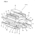
Figure 4 is an exploded perspective view of the crosspiece assembly in accordance with the invention; -
Figures 5 and 6 are respectively a side and a front view with some parts cut away to better illustrate others of the crosspiece assembly ofFigure 4 ; -
Figure 7 is a perspective view with some parts cut away and others in cross-section of a detail of the crosspiece assembly fromFigures 4 to 6 ; -
Figure 8 is a schematic front view of a sliding window or door obtained with the crosspiece assembly in accordance with the present invention. - With reference to the accompanying drawings, and in particular with reference to
Figures 3 and4 , the accessory, labelled 11 as a whole, is applied onprofiles 7 used to make frames for sliding windows or doors 1 comprising, amongst other things, (Figure 7 ) afixed frame 2 formed by twocrosspieces 3 and 4 and twostiles - As
Figure 3 clearly shows, theprofile 7, forming at least the firstlower crosspiece 3, comprises twosliding tracks lower base body 10, and also comprisesheat insulation elements 12. - Positioned on the two
tracks movable frame 50 and a second frame (movable or static) 51 which completes the structure of the sliding window or door 1. -
Figure 3 also shows how theprofile 7 forming thelower crosspiece 3 has anelement 11 for connecting and joining twohalves profile 7, separated transversally relative to the length of thetracks lower crosspiece 3. - In addition, the connecting and joining
element 11 has heat insulation properties. - Obviously, the profile 7' forming the upper crosspiece 4 also has a second element 11' for connecting and joining the two halves 7'a and 7'b forming the profile 7', again separated transversally relative to the length of the
tracks - Again, the connecting and joining element 11' has heat insulation properties.
- To simplify the description, reference is made to one
element 11 or 11', since these accessory elements are both the same in terms of architecture and structural equipment. - This connecting and joining
element 11, 11' forms the central portion of theprofile 7, 7' where thehalves - As illustrated in
Figures 4 to 6 , each connecting and joiningelement 11, 11' comprises: - a
base portion 13 which can be connected with a matching fit, on both sides, with the respective base ends of eachhalf profile 7, 7' byrelative connection elements 14 projecting from both sides of thebase portion 13; - two pairs of
upper projections second tracks half longitudinal track profile 7, 7'. - In more detail, for each end side in contact with the
halves base portion 13 comprises at least onevertical surface 17 for contact with the heat insulation orthermal break elements 12, 12' positioned on thecorresponding halves profile 7, 7' (for example, one or more flat rods extending below thetracks 8 and 9). - In addition, the
base portion 13 may comprise, on the upper surface inserted between the two pairs ofupper projections seal element 18 or seal (for example made of rubber) between the two upper zones of eachhalf - An additional feature of this
element 11, 11' is the presence, on one or, preferably, both end sides of thebase portion 13, of an opening orslot 19 for the passage, in practice, of fluid, that is to say rain, so as to collect the latter in a lower part of thebase portion 13, having a reservoir-styleinner zone 20 for collecting the water. - Connected on one side of the lower part, in practice positioned towards the outside of the environment in which it is mounted, there is a
valve element 21 designed to allow the water collected to be emptied to the outside. - In more detail, the valve element consists of a
rigid wall 21 pivoting at both sides in the lower part of thebase portion 13. - The
rigid wall 21, substantially forming a door, is positioned close to an opening 13a made on the side part of thebase portion 13 so that, when therigid wall 21 is rotated (due to the quantity of water present in the reservoir 20), the water collected is emptied out (see arrows F20 and F21 inFigures 6 and 7 ) . - In order to correctly apply the
rigid wall 21 inside the connecting and joiningelement 11, 11', thebase portion 13 may be divided into two halves, upper 13b and lower 13c, which can be connected during assembly to form theelement 11, 11'. - The
connection elements 14 may vary in shape and number depending on the type of cross-section of thehalves profile 7, 7'. - In the case illustrated, by way of example only and without limiting the scope of the invention, the
connection elements 14 consist of ahorizontal projection 22 projecting from each of the end sides of thebase portion 13 and connecting, with a matching fit, by sliding, with a portion of therelative half profile 7, 7'. - In addition there is a pair of
second rods base portion 13, eachpair horizontal projection 22 and designed to connect with a matching fit, by sliding, in a relative portion of acorresponding half profile 7, 7'. - Therefore, with an accessory structured in this way the preset aims are achieved with a simple architectural variation of the conventional type of profiles and the addition of the connecting and joining
element 11, 11'. - The presence of the accessory allows heat seal results to be achieved which are better than those on conventional profiles.
- Interrupting the lower and, if necessary, upper tracks, connecting with the insertion of the joining accessory or plug, allows the creation of an effective thermal barrier which, for each surface facing the outside, has a thermal break system without any uninterrupted element between the inside and the outside.
- Finally, with this accessory, the profile made in this way achieves a plurality of advantages which may be summarised as follows:
- improved overall thermal performance of the sliding window or door mounted;
- reduced working on the frame profile;
- improved resistance to infiltration by water thanks to the increase in the capacity of the drainage devices and the structuring of the joining plug, without the need for additional work on the profile;
- improved frame transportability thanks to the possibility of assembling the plugs on site and therefore with greatly reduced crosspiece sizing;
- simplification of the process for making the window or door as a whole.
- The invention described above is susceptible of industrial application and may be modified and adapted in several ways without thereby departing from the scope of the inventive concept. Moreover, all details of the invention may be substituted by technically equivalent elements.
Claims (12)
- A crosspiece assembly for frames for sliding windows or doors (1) comprising at least one fixed frame (2) formed by two crosspieces (3, 4) and two stiles (5, 6); the crosspiece assembly comprising- a profile (7) forming at least a lower crosspiece (3); said profile (7) having:- two sliding tracks (8, 9), parallel with one another;- a lower base aluminium body (10) of the thermal break type, this is with heat insulation connecting elements (12), presenting said sliding tracks (8, 9); and- an accessory (11);
said crosspiece assembly being characterised in that
said profile (7) forming said lower crosspiece (3) is separated transversally relative to the length of the tracks (8, 9) into two halves (7a, 7b); and- said accessory (11) is defined by an element (11) connecting and joining the two halves (7a, 7b) in order to form the whole first lower crosspiece (3); said accessory (11) having heat insulation properties. - The crosspiece assembly according to claim 1, characterised in that at least the profile (7') forming the upper crosspiece (4) has a second element (11') for connecting and joining two halves (7'a, 7'b) of the profile (7'), separated transversally relative to the length of the tracks (8, 9) and forming the entire upper crosspiece (4); the connecting and joining element (11') having heat insulation properties.
- The crosspiece assembly according to claim 1 or 2, characterised in that the connecting and joining element (11, 11') forms the central portion of the profile (7, 7') in which the halves (7a, 7b, 7'a, 7'b) are separated transversally and with equal length.
- The crosspiece assembly according to claim 1 or 2, characterised in that each connecting and joining element (11, 11') comprises:- a base portion (13) which can be connected with a matching fit, on both sides, with the respective base ends of each half (7a, 7b, 7'a, 7'b) of the profile (7, 7') by relative connection elements (14) projecting from both sides of the base portion (13);- two pairs of upper projections (15, 16), parallel with one another, forming relative connections or joins for the first and second tracks (8, 9) of each half (7a, 7b, 7'a, 7'b), and so as to obtain, in practice, a relative first and second longitudinal track (8, 9) without interruption along the entire length of the profile (7, 7').
- The crosspiece assembly according to claim 4, characterised in that, for each end side in contact with the halves (7a, 7b, 7'a, 7'b) the base portion (13) comprises at least one vertical surface (17) for contact with heat insulation or thermal break elements (12, 12') positioned on the corresponding halves (7a, 7b, 7'a, 7'b) of the profile (7, 7').
- The crosspiece assembly according to claim 4, characterised in that the base portion (13) comprises, on the upper surface inserted between the two pairs of upper projections (15, 16), a seal element (18) or seal between the two upper zones of each half (7a, 7b, 7'a, 7'b).
- The crosspiece assembly according to claim 4, characterised in that at least on one end side of the base portion (13) there is an opening or slot (19) for the passage, in practice, of fluid, that is to say rain, so as to collect the latter in a lower part of the base portion (13), having a reservoir-style inner zone (20) for collecting the water; there being connected on one side of the lower part, positioned towards the outside of the environment in which it is mounted, a valve element (21) designed to allow the water collected to be emptied to the outside.
- The crosspiece assembly according to claim 7, characterised in that the valve element consists of a rigid wall (21) pivoting at both sides in the lower part of the base portion (13); the rigid wall (21) being positioned close to an opening (13a) made on the side part of the base portion (13) so that, when the rigid wall (21) is rotated, the water collected is emptied out.
- The crosspiece assembly according to claim 4, characterised in that on both end sides of the base portion (13) there is an opening or slot (19) for the passage, in practice, of fluid, that is to say rain, so as to collect the latter in a lower part of the base portion (13), having a reservoir-style inner zone (20) for collecting the water.
- The crosspiece assembly according to claim 4, characterised in that the connection elements (14) consist of at least one horizontal projection (22) projecting from each of the end sides of the base portion (13) and connecting with a matching fit with a portion of the relative half (7a, 7b, 7'a, 7'b) of the profile (7, 7').
- The crosspiece assembly according to claim 4, characterised in that the connection elements (14) consist of a first horizontal projection (22) projecting from each of the end sides of the base portion (13) and connecting with a matching fit with a portion of the relative half (7a, 7b, 7'a, 7'b) of the profile (7, 7'); there being a pair of second rods (23, 24), projecting from the relative end sides of the base portion (13), each pair of second rods (23, 24 being positioned on both sides of the first horizontal projection (22) and designed to connect with a matching fit in a relative portion of a corresponding half (7a, 7b, 7'a, 7'b) of the profile (7, 7').
- The crosspiece assembly according to claim 4, characterised in that the base portion (13) is divided into two halves, upper (13b) and lower (13c), which can be connected during assembly.
Applications Claiming Priority (1)
| Application Number | Priority Date | Filing Date | Title |
|---|---|---|---|
| IT000243A ITBO20070243A1 (en) | 2007-04-03 | 2007-04-03 | ACCESSORY FOR PROFILES FOR SLIDING DOORS. |
Publications (2)
| Publication Number | Publication Date |
|---|---|
| EP1978198A1 EP1978198A1 (en) | 2008-10-08 |
| EP1978198B1 true EP1978198B1 (en) | 2012-04-18 |
Family
ID=38753519
Family Applications (1)
| Application Number | Title | Priority Date | Filing Date |
|---|---|---|---|
| EP07113799A Active EP1978198B1 (en) | 2007-04-03 | 2007-08-03 | Crosspiece assembly for sliding windows or doors |
Country Status (5)
| Country | Link |
|---|---|
| US (1) | US8001743B2 (en) |
| EP (1) | EP1978198B1 (en) |
| CN (1) | CN101280660B (en) |
| AT (1) | ATE554258T1 (en) |
| IT (1) | ITBO20070243A1 (en) |
Families Citing this family (11)
| Publication number | Priority date | Publication date | Assignee | Title |
|---|---|---|---|---|
| US8857129B2 (en) | 2011-11-03 | 2014-10-14 | Proformance Maufacturing, Inc. | Frame assembly having a corner key |
| US8511011B2 (en) * | 2011-11-03 | 2013-08-20 | James Hardie Technology Limited | Structural frame member having a capped corner key passage |
| US20140053488A1 (en) * | 2012-08-22 | 2014-02-27 | Alcoa Inc. | Inserts for hollow structural members |
| US9234380B2 (en) | 2013-03-13 | 2016-01-12 | Technoform Bautec North America, Inc. | Thermally insulating composite frame apparatus with slide-in thermal isolator and method for making same |
| US9127498B1 (en) * | 2014-03-07 | 2015-09-08 | Jintian Ye | Insulating window frame |
| EP3034745B1 (en) * | 2014-12-18 | 2020-02-12 | dormakaba Deutschland GmbH | Slidable wall system |
| KR20170133190A (en) * | 2016-05-25 | 2017-12-05 | 주식회사 필로브 | Installation Structure for Connecting Modulized Windows |
| WO2019018454A1 (en) | 2017-07-18 | 2019-01-24 | Cohen Shmulik | Thermally-efficient slidable fenestration assembly |
| DE102017123074A1 (en) * | 2017-10-05 | 2019-04-11 | Agtatec Ag | Automatic door system, in particular in the form of a sliding door or a telescopic sliding door or a folding door |
| IT201800009914A1 (en) * | 2018-10-30 | 2020-04-30 | Effegi Brevetti Srl | SUPPORT AND / OR GUIDE SYSTEM FOR DOORS FOR WARDROBES WITH SLIDING DOORS |
| JP7071610B2 (en) * | 2020-02-09 | 2022-05-19 | ケージーパルテック株式会社 | Single rail connecting member, parallel rail connecting member, single rail installation structure for floor, and parallel rail installation structure for floor |
Family Cites Families (99)
| Publication number | Priority date | Publication date | Assignee | Title |
|---|---|---|---|---|
| US2067118A (en) * | 1936-03-27 | 1937-01-05 | Luzerne Rubber Company | Sliding door for display cases |
| CH321043A (en) * | 1954-01-05 | 1957-04-30 | Lehni Rudolf | frame |
| US2931434A (en) * | 1957-08-27 | 1960-04-05 | John F Steel | Sliding glass door construction |
| US3106754A (en) * | 1960-09-26 | 1963-10-15 | Grossman Abraham | Dual movable sash window |
| US3114943A (en) * | 1960-11-10 | 1963-12-24 | Ralph T Casebolt | Sliding door assembly |
| US3114179A (en) * | 1960-12-01 | 1963-12-17 | Window Products Inc | Heat-insulated metal-framed closure |
| US3136396A (en) * | 1962-09-10 | 1964-06-09 | Jack G Sullivan | Reversible sliding door panels |
| US3340663A (en) | 1965-06-17 | 1967-09-12 | Earl W Collard | Interlocking window framing system |
| US3402510A (en) | 1966-04-22 | 1968-09-24 | Weather Seal Inc | Combined metal and wood side jambs for a window and sash assembly |
| US3403490A (en) * | 1966-07-18 | 1968-10-01 | Roy H. Luedtke | Metal window construction |
| US3420026A (en) * | 1966-10-06 | 1969-01-07 | Reynolds Metals Co | Thermal insulating apparatus and method of making same |
| US3393487A (en) * | 1966-10-06 | 1968-07-23 | Reynolds Metals Co | Thermally insulating joint construction |
| US3503169A (en) * | 1968-02-05 | 1970-03-31 | Vac Inc De | Self-draining window sill |
| US3487580A (en) | 1968-03-15 | 1970-01-06 | Reynolds Metals Co | Thermal break window construction |
| US3462884A (en) * | 1968-04-30 | 1969-08-26 | Alpana Aluminum Prod | Insulated metal frame and sliding closure |
| US3600857A (en) | 1969-06-11 | 1971-08-24 | Aluminum Co Of America | Insulated window assembly with movable sash |
| US3628289A (en) * | 1970-05-25 | 1971-12-21 | Beverage Air Co | Sliding door construction |
| DE2143698A1 (en) * | 1971-09-01 | 1973-07-26 | Dynamit Nobel Ag | EXTRUDED PROFILES, PREFERABLY MADE OF A THERMOPLASTIC PLASTIC, FOR FRAMES AND SASH FRAMES OF SLIDING WINDOWS, SLIDING DOORS OR THE LIKE |
| US3818666A (en) * | 1972-03-17 | 1974-06-25 | Metalume Mfg Co Inc | Thermal barrier for frame structures |
| US3823524A (en) * | 1973-01-12 | 1974-07-16 | Alusuisse | Thermal break type architectural extrusions |
| US3925953A (en) * | 1974-04-08 | 1975-12-16 | Ethyl Corp | Method of making a thermal break construction element |
| US3947998A (en) * | 1974-09-19 | 1976-04-06 | Yoshida Kogyo Kabushiki Kaisha | Dual sash window assembly with weathertight sealing means |
| DE2608686A1 (en) * | 1976-03-03 | 1977-09-08 | Erbsloeh Julius & August | Insulated sliding window or door blind frame - has insulating pieces and part bars connecting centre rail breaks |
| US4257202A (en) | 1976-03-10 | 1981-03-24 | Armcor Industries, Inc. | Aluminum frame window with improved thermal insulation and method of making same |
| US4064653A (en) * | 1976-10-29 | 1977-12-27 | Three Rivers Aluminum Company | Sliding window |
| US4114317A (en) * | 1976-12-20 | 1978-09-19 | Crawley Richard K | Window and door construction |
| SE437395B (en) * | 1977-05-12 | 1985-02-25 | Hueck Fa E | COMPOSITION PROFILE FOR WINDOWS AND DORRAMS AND PROCEDURE FOR PRODUCING ITS |
| US4164830A (en) * | 1977-12-16 | 1979-08-21 | Bierlich J H | Double-glazed doors or windows and frame assemblies therefor |
| DE2839740C2 (en) | 1978-09-13 | 1986-04-30 | SCHÜCO Heinz Schürmann & Co, 4800 Bielefeld | Sliding, lift and slide window or door |
| DE2842884A1 (en) * | 1978-10-02 | 1980-04-17 | Dynamit Nobel Ag | KIT FOR VERTICAL OR HORIZONTAL SLIDING WINDOWS |
| US4280309A (en) * | 1978-11-06 | 1981-07-28 | Huelsekopf Alfred G | Window frame assembly |
| US4222200A (en) | 1979-02-05 | 1980-09-16 | Beirnes James R | Combination window casing and storm window frame |
| US4304072A (en) * | 1979-10-24 | 1981-12-08 | Pegg Owen C | Double-hung replacement window unit |
| NO145021C (en) | 1979-11-13 | 1981-12-28 | Voss L L Mobel & Trevare | PUSHING DOER FRAME. |
| US4483099A (en) | 1980-01-21 | 1984-11-20 | Capitol Products Corporation | Window assembly |
| DE3024555A1 (en) * | 1980-06-28 | 1982-01-21 | Dynamit Nobel Ag, 5210 Troisdorf | SLIDING WINDOW |
| SE445751B (en) | 1981-11-09 | 1986-07-14 | Lindstroem Wictor Carl Olof | BACK PROFILE FOR WINDOWS AND DOORS |
| GB2110283B (en) | 1981-11-27 | 1986-08-13 | Lb | Frame for patio doors |
| US4478020A (en) | 1981-12-15 | 1984-10-23 | The Standard Products Company | Window reveal molding |
| US4447985A (en) | 1982-06-16 | 1984-05-15 | Wausau Metals Corporation | Window structure |
| GB2127470B (en) | 1982-09-23 | 1985-09-11 | Schnicks Gmbh & Co Carl | A composite window frame |
| CA1234510A (en) | 1983-02-07 | 1988-03-29 | Jean-Paul Giguere | Double glazed sealed sliding window |
| US4569154A (en) | 1983-11-28 | 1986-02-11 | Thermal-Barrier Products, Inc. | Thermally insulating window assembly |
| US4554770A (en) | 1984-01-11 | 1985-11-26 | National Gypsum Company | Horizontal sliding window with removable fixed sash |
| US4624091A (en) * | 1984-07-20 | 1986-11-25 | Winchester Industries, Inc. | Thermally insulated window sash construction |
| US4686805A (en) * | 1985-02-21 | 1987-08-18 | Jarl Extrusions, Inc. | Panel support |
| US4680905A (en) * | 1985-08-26 | 1987-07-21 | Ppg Industries, Inc. | Rafter with internal drainage feature and sloped glazing system incorporating same |
| US4704839A (en) * | 1985-12-06 | 1987-11-10 | Products Research & Chemical Corporation | Thermal barrier extrusion |
| US4922658A (en) * | 1986-04-11 | 1990-05-08 | Therm-O-Loc, Inc. | Sliding storm door or window assembly |
| US4958468A (en) * | 1986-05-07 | 1990-09-25 | United Technologies Automotive, Inc. | Combination support and attachment bar for a window |
| US4725324A (en) * | 1986-07-25 | 1988-02-16 | Capitol Products Corporation | Method of making a thermal barrier construction element |
| US4691487A (en) * | 1986-07-31 | 1987-09-08 | Gerald Kessler | Drain tube for windows |
| CA1295189C (en) * | 1986-08-28 | 1992-02-04 | Viceroy Homes Limited | Sliding door |
| US4763446A (en) | 1986-09-05 | 1988-08-16 | Kelly Donald V | Low sound, thermal and air penetration sliding window |
| GB2197903A (en) | 1986-11-24 | 1988-06-02 | Austria Metall | A window assembly |
| CA1259858A (en) | 1986-12-09 | 1989-09-26 | Fred Haas | Picture or casement window |
| US4875316A (en) | 1987-03-27 | 1989-10-24 | Johnston Bernard A | Combination metal and wood window frame assembly |
| CA1292912C (en) * | 1987-07-23 | 1991-12-10 | Fred Haas | Sliding window |
| US5038538A (en) | 1988-10-06 | 1991-08-13 | Rozon David P | Door frame |
| US4922666A (en) | 1989-02-02 | 1990-05-08 | Rotter Bernard J | Porch with recessible windows |
| US5099624A (en) | 1990-06-18 | 1992-03-31 | L.B. Plastics Limited | Window systems |
| US5065544A (en) * | 1990-10-10 | 1991-11-19 | Thomas B. Nuckolls | Window assembly |
| CH682341A5 (en) * | 1990-12-20 | 1993-08-31 | Formplast Ag | Connector for joining two corner profile rails - involves insertion of connector in hollow space of rails which aligns two ends exactly with each other |
| CA2059505A1 (en) | 1991-01-17 | 1992-07-18 | Thomas J. Heppner | Sliding door sill construction |
| CA2062285A1 (en) | 1991-03-07 | 1992-09-08 | Lawrence W. Davies | Sliding window or door arrangement |
| US5103589A (en) | 1991-04-22 | 1992-04-14 | Crawford Ralph E | Sliding panel security assembly and method |
| US5285606A (en) * | 1991-11-18 | 1994-02-15 | Pella Corporation | Window and door assembly manufactured in half sections and method of installing same |
| US5363628A (en) * | 1992-02-05 | 1994-11-15 | Alumax Extrusions, Inc. | Thermal barrier apparatus and process for fabricating same |
| NL191028C (en) | 1993-02-17 | 1994-12-16 | Handelsonderneming Pega Best B | Sliding door. |
| US5603585A (en) * | 1994-05-17 | 1997-02-18 | Andersen Corporation | Joint structure and method of manufacture |
| US5553420A (en) * | 1994-08-29 | 1996-09-10 | Sne Enterprises, Inc. | Casement window |
| US5653060A (en) | 1994-08-31 | 1997-08-05 | Ykk Architectural Products Inc. | Sliding window structure |
| US5555684A (en) * | 1994-10-19 | 1996-09-17 | Andersen Corporation | Method and apparatus for securing interior trim to a window frame |
| TW289780B (en) * | 1994-11-30 | 1996-11-01 | Ykk Architecture Product Kk | |
| CN2260157Y (en) * | 1996-05-24 | 1997-08-20 | 孙玉琦 | Energy-saving sealing type thermal insulation aluminium alloy sliding window |
| DE29609762U1 (en) * | 1996-06-01 | 1996-08-14 | Magna Zippex Autotechnik Gmbh | Border and frame for built-in windows |
| US5713167A (en) * | 1996-07-23 | 1998-02-03 | Durham; Robert C. | Glazing system |
| US5799449A (en) * | 1996-09-26 | 1998-09-01 | Excel Industries, Inc. | Snap-fit sliding window assembly |
| US6393778B1 (en) * | 1997-07-03 | 2002-05-28 | Raymond M. L. Ting | Airloop window system |
| US6311439B1 (en) * | 1997-09-26 | 2001-11-06 | Thomas Arcati | Window frame |
| US6094874A (en) | 1998-03-26 | 2000-08-01 | Thermo-Roll Window Corp. | Window mount system |
| US6098355A (en) * | 1998-12-09 | 2000-08-08 | Li; Ching-Chi | Sliding-type window frame for mounting a window panel assembly |
| US6243999B1 (en) | 1999-05-04 | 2001-06-12 | Silver Line Building Products Corporation | Blow-out prevention mechanism for windows |
| US6209269B1 (en) * | 1999-05-06 | 2001-04-03 | Mario Valderrama | Assembly system for thermoacoustic windows |
| US6318036B1 (en) * | 1999-11-12 | 2001-11-20 | Dayton Technologies, L.L.C. | Patio door assembly with extruded plastics components |
| DE10015986C2 (en) * | 2000-03-31 | 2002-08-01 | Schueco Int Kg | Composite profile and method for producing a composite profile |
| US6360498B1 (en) * | 2000-06-30 | 2002-03-26 | Certainteed Corp. | Two-piece mullion reinforcement |
| WO2002044506A1 (en) * | 2000-12-01 | 2002-06-06 | Tateyama Aluminium Industry Co., Ltd. | Outdoor sash structure having lower frame with flat upper surface |
| US20030084622A1 (en) * | 2001-11-05 | 2003-05-08 | Sashlite, Llc | Components for multipane window unit sash assemblies |
| IE20020111A1 (en) * | 2002-02-14 | 2003-08-20 | Architectural & Metal Systems | Manufacture of thermally insulated frame members |
| ATE403057T1 (en) * | 2002-04-10 | 2008-08-15 | Guhl Beat | FRAME CONSTRUCTION OF A SLIDING DOOR |
| CA2384213C (en) | 2002-04-30 | 2008-10-07 | Tetsuya Kobayashi | Sliding door assembly |
| FR2844825B1 (en) | 2002-09-19 | 2005-10-28 | Jean Paul Tisserand | WINDOW OR WINDOW DOOR, SLIDING WITH BLOCKABLE VENTS IN SEALED SUPPORT ON THE DORMANT |
| CA2462409C (en) * | 2003-03-27 | 2005-09-13 | Alpa Lumber Inc. | Improved frame assembly for windows or doors |
| US7065929B2 (en) | 2003-08-12 | 2006-06-27 | Francis Manzella | Two part window and door assembly and coupling for interconnecting components thereof |
| DE10353822A1 (en) * | 2003-11-18 | 2005-06-23 | Eduard Hueck Gmbh & Co Kg | Sill profile for sliding door or sliding window has three metal profile beams separated by insulating strips and has void in region where door edges overlap when door is closed |
| US7520093B2 (en) * | 2004-01-13 | 2009-04-21 | Beat Guhl | Frame construction of a sliding door |
| US7246466B2 (en) | 2004-07-21 | 2007-07-24 | Hi-Tech Energy Windows Ltd. | Extruded profile system for forming sliding fenestration products |
| US7637058B2 (en) * | 2005-03-09 | 2009-12-29 | Chin-Ming Lai | Wind and rain preventing device for aluminum doors and windows |
-
2007
- 2007-04-03 IT IT000243A patent/ITBO20070243A1/en unknown
- 2007-08-03 AT AT07113799T patent/ATE554258T1/en active
- 2007-08-03 EP EP07113799A patent/EP1978198B1/en active Active
- 2007-08-27 US US11/845,562 patent/US8001743B2/en active Active
- 2007-08-30 CN CN2007101596290A patent/CN101280660B/en active Active
Also Published As
| Publication number | Publication date |
|---|---|
| CN101280660A (en) | 2008-10-08 |
| EP1978198A1 (en) | 2008-10-08 |
| US20080245000A1 (en) | 2008-10-09 |
| ITBO20070243A1 (en) | 2008-10-04 |
| US8001743B2 (en) | 2011-08-23 |
| ATE554258T1 (en) | 2012-05-15 |
| CN101280660B (en) | 2012-12-05 |
Similar Documents
| Publication | Publication Date | Title |
|---|---|---|
| EP1978198B1 (en) | Crosspiece assembly for sliding windows or doors | |
| EP1978197B1 (en) | Profile for sliding windows or doors, method for making the profile, and window or door obtained with the profile | |
| KR101339951B1 (en) | Lift-and-sliding system window having aluminum window frame for high thermal insulating | |
| KR101217766B1 (en) | A Curtain Wall Window Frame | |
| CN210178201U (en) | Heat insulation single side fixed screen window rail-changing sliding window | |
| KR101872970B1 (en) | Structure of window frame | |
| KR200482596Y1 (en) | Insulated windows and doors frames | |
| KR101765548B1 (en) | the zigzag assembly type structure of insulation window frames as well as window and doors | |
| EP2137369B1 (en) | Profile for sliding doors and windows, method for making the profile and door or window made with the profile | |
| JPH0726843A (en) | Heat insulating sash | |
| KR101471244B1 (en) | Double sliding window | |
| KR101234273B1 (en) | Window and door frame | |
| KR101783753B1 (en) | Insulated windows and doors frames | |
| KR102325103B1 (en) | Heat-insulating window frame being capable of preventing rainwater from backflowing | |
| WO2014182113A1 (en) | Window with detachably mounted insulation reinforcing member | |
| CN218150457U (en) | Novel integrated structure of mullion-free split window screen | |
| EP1967682B1 (en) | Elevating sliding window or door with sealing arrangements | |
| KR100538008B1 (en) | A double-glazed window frame structure | |
| KR102030411B1 (en) | Window System | |
| KR102330056B1 (en) | Insulation window with multiple insulation chamber for improve insulation performance | |
| JP6918034B2 (en) | Joinery | |
| GB2371074A (en) | Glazing frame | |
| CN209413684U (en) | Drift about window mullion and drift window | |
| KR102600327B1 (en) | Sliding double windows for smoke exhaust and ventilation with built-in window opening and closing devices | |
| JP7296816B2 (en) | Fire prevention structure of hidden frame outside sliding single sliding window |
Legal Events
| Date | Code | Title | Description |
|---|---|---|---|
| PUAI | Public reference made under article 153(3) epc to a published international application that has entered the european phase |
Free format text: ORIGINAL CODE: 0009012 |
|
| 17P | Request for examination filed |
Effective date: 20080618 |
|
| AK | Designated contracting states |
Kind code of ref document: A1 Designated state(s): AT BE BG CH CY CZ DE DK EE ES FI FR GB GR HU IE IS IT LI LT LU LV MC MT NL PL PT RO SE SI SK TR |
|
| AX | Request for extension of the european patent |
Extension state: AL BA HR MK RS |
|
| AKX | Designation fees paid |
Designated state(s): AT BE BG CH CY CZ DE DK EE ES FI FR GB GR HU IE IS IT LI LT LU LV MC MT NL PL PT RO SE SI SK TR |
|
| RTI1 | Title (correction) |
Free format text: CROSSPIECE ASSEMBLY FOR SLIDING WINDOWS OR DOORS |
|
| GRAP | Despatch of communication of intention to grant a patent |
Free format text: ORIGINAL CODE: EPIDOSNIGR1 |
|
| GRAS | Grant fee paid |
Free format text: ORIGINAL CODE: EPIDOSNIGR3 |
|
| GRAA | (expected) grant |
Free format text: ORIGINAL CODE: 0009210 |
|
| AK | Designated contracting states |
Kind code of ref document: B1 Designated state(s): AT BE BG CH CY CZ DE DK EE ES FI FR GB GR HU IE IS IT LI LT LU LV MC MT NL PL PT RO SE SI SK TR |
|
| REG | Reference to a national code |
Ref country code: GB Ref legal event code: FG4D |
|
| REG | Reference to a national code |
Ref country code: CH Ref legal event code: EP |
|
| REG | Reference to a national code |
Ref country code: IE Ref legal event code: FG4D |
|
| REG | Reference to a national code |
Ref country code: AT Ref legal event code: REF Ref document number: 554258 Country of ref document: AT Kind code of ref document: T Effective date: 20120515 |
|
| REG | Reference to a national code |
Ref country code: DE Ref legal event code: R096 Ref document number: 602007022062 Country of ref document: DE Effective date: 20120614 |
|
| REG | Reference to a national code |
Ref country code: NL Ref legal event code: VDEP Effective date: 20120418 |
|
| REG | Reference to a national code |
Ref country code: AT Ref legal event code: MK05 Ref document number: 554258 Country of ref document: AT Kind code of ref document: T Effective date: 20120418 |
|
| LTIE | Lt: invalidation of european patent or patent extension |
Effective date: 20120418 |
|
| PG25 | Lapsed in a contracting state [announced via postgrant information from national office to epo] |
Ref country code: SE Free format text: LAPSE BECAUSE OF FAILURE TO SUBMIT A TRANSLATION OF THE DESCRIPTION OR TO PAY THE FEE WITHIN THE PRESCRIBED TIME-LIMIT Effective date: 20120418 Ref country code: IS Free format text: LAPSE BECAUSE OF FAILURE TO SUBMIT A TRANSLATION OF THE DESCRIPTION OR TO PAY THE FEE WITHIN THE PRESCRIBED TIME-LIMIT Effective date: 20120818 Ref country code: CY Free format text: LAPSE BECAUSE OF FAILURE TO SUBMIT A TRANSLATION OF THE DESCRIPTION OR TO PAY THE FEE WITHIN THE PRESCRIBED TIME-LIMIT Effective date: 20120418 Ref country code: FI Free format text: LAPSE BECAUSE OF FAILURE TO SUBMIT A TRANSLATION OF THE DESCRIPTION OR TO PAY THE FEE WITHIN THE PRESCRIBED TIME-LIMIT Effective date: 20120418 Ref country code: PL Free format text: LAPSE BECAUSE OF FAILURE TO SUBMIT A TRANSLATION OF THE DESCRIPTION OR TO PAY THE FEE WITHIN THE PRESCRIBED TIME-LIMIT Effective date: 20120418 Ref country code: LT Free format text: LAPSE BECAUSE OF FAILURE TO SUBMIT A TRANSLATION OF THE DESCRIPTION OR TO PAY THE FEE WITHIN THE PRESCRIBED TIME-LIMIT Effective date: 20120418 |
|
| PG25 | Lapsed in a contracting state [announced via postgrant information from national office to epo] |
Ref country code: GR Free format text: LAPSE BECAUSE OF FAILURE TO SUBMIT A TRANSLATION OF THE DESCRIPTION OR TO PAY THE FEE WITHIN THE PRESCRIBED TIME-LIMIT Effective date: 20120719 Ref country code: SI Free format text: LAPSE BECAUSE OF FAILURE TO SUBMIT A TRANSLATION OF THE DESCRIPTION OR TO PAY THE FEE WITHIN THE PRESCRIBED TIME-LIMIT Effective date: 20120418 Ref country code: LV Free format text: LAPSE BECAUSE OF FAILURE TO SUBMIT A TRANSLATION OF THE DESCRIPTION OR TO PAY THE FEE WITHIN THE PRESCRIBED TIME-LIMIT Effective date: 20120418 Ref country code: PT Free format text: LAPSE BECAUSE OF FAILURE TO SUBMIT A TRANSLATION OF THE DESCRIPTION OR TO PAY THE FEE WITHIN THE PRESCRIBED TIME-LIMIT Effective date: 20120820 |
|
| PG25 | Lapsed in a contracting state [announced via postgrant information from national office to epo] |
Ref country code: BE Free format text: LAPSE BECAUSE OF FAILURE TO SUBMIT A TRANSLATION OF THE DESCRIPTION OR TO PAY THE FEE WITHIN THE PRESCRIBED TIME-LIMIT Effective date: 20120418 |
|
| PG25 | Lapsed in a contracting state [announced via postgrant information from national office to epo] |
Ref country code: EE Free format text: LAPSE BECAUSE OF FAILURE TO SUBMIT A TRANSLATION OF THE DESCRIPTION OR TO PAY THE FEE WITHIN THE PRESCRIBED TIME-LIMIT Effective date: 20120418 Ref country code: NL Free format text: LAPSE BECAUSE OF FAILURE TO SUBMIT A TRANSLATION OF THE DESCRIPTION OR TO PAY THE FEE WITHIN THE PRESCRIBED TIME-LIMIT Effective date: 20120418 Ref country code: DK Free format text: LAPSE BECAUSE OF FAILURE TO SUBMIT A TRANSLATION OF THE DESCRIPTION OR TO PAY THE FEE WITHIN THE PRESCRIBED TIME-LIMIT Effective date: 20120418 Ref country code: SK Free format text: LAPSE BECAUSE OF FAILURE TO SUBMIT A TRANSLATION OF THE DESCRIPTION OR TO PAY THE FEE WITHIN THE PRESCRIBED TIME-LIMIT Effective date: 20120418 Ref country code: AT Free format text: LAPSE BECAUSE OF FAILURE TO SUBMIT A TRANSLATION OF THE DESCRIPTION OR TO PAY THE FEE WITHIN THE PRESCRIBED TIME-LIMIT Effective date: 20120418 Ref country code: CZ Free format text: LAPSE BECAUSE OF FAILURE TO SUBMIT A TRANSLATION OF THE DESCRIPTION OR TO PAY THE FEE WITHIN THE PRESCRIBED TIME-LIMIT Effective date: 20120418 Ref country code: RO Free format text: LAPSE BECAUSE OF FAILURE TO SUBMIT A TRANSLATION OF THE DESCRIPTION OR TO PAY THE FEE WITHIN THE PRESCRIBED TIME-LIMIT Effective date: 20120418 |
|
| PLBE | No opposition filed within time limit |
Free format text: ORIGINAL CODE: 0009261 |
|
| STAA | Information on the status of an ep patent application or granted ep patent |
Free format text: STATUS: NO OPPOSITION FILED WITHIN TIME LIMIT |
|
| 26N | No opposition filed |
Effective date: 20130121 |
|
| REG | Reference to a national code |
Ref country code: CH Ref legal event code: PL |
|
| PG25 | Lapsed in a contracting state [announced via postgrant information from national office to epo] |
Ref country code: MC Free format text: LAPSE BECAUSE OF NON-PAYMENT OF DUE FEES Effective date: 20120831 |
|
| GBPC | Gb: european patent ceased through non-payment of renewal fee |
Effective date: 20120803 |
|
| PG25 | Lapsed in a contracting state [announced via postgrant information from national office to epo] |
Ref country code: CH Free format text: LAPSE BECAUSE OF NON-PAYMENT OF DUE FEES Effective date: 20120831 Ref country code: LI Free format text: LAPSE BECAUSE OF NON-PAYMENT OF DUE FEES Effective date: 20120831 |
|
| REG | Reference to a national code |
Ref country code: DE Ref legal event code: R097 Ref document number: 602007022062 Country of ref document: DE Effective date: 20130121 |
|
| REG | Reference to a national code |
Ref country code: IE Ref legal event code: MM4A |
|
| PG25 | Lapsed in a contracting state [announced via postgrant information from national office to epo] |
Ref country code: GB Free format text: LAPSE BECAUSE OF NON-PAYMENT OF DUE FEES Effective date: 20120803 Ref country code: BG Free format text: LAPSE BECAUSE OF FAILURE TO SUBMIT A TRANSLATION OF THE DESCRIPTION OR TO PAY THE FEE WITHIN THE PRESCRIBED TIME-LIMIT Effective date: 20120718 Ref country code: IE Free format text: LAPSE BECAUSE OF NON-PAYMENT OF DUE FEES Effective date: 20120803 |
|
| PG25 | Lapsed in a contracting state [announced via postgrant information from national office to epo] |
Ref country code: ES Free format text: LAPSE BECAUSE OF FAILURE TO SUBMIT A TRANSLATION OF THE DESCRIPTION OR TO PAY THE FEE WITHIN THE PRESCRIBED TIME-LIMIT Effective date: 20120729 |
|
| PG25 | Lapsed in a contracting state [announced via postgrant information from national office to epo] |
Ref country code: MT Free format text: LAPSE BECAUSE OF FAILURE TO SUBMIT A TRANSLATION OF THE DESCRIPTION OR TO PAY THE FEE WITHIN THE PRESCRIBED TIME-LIMIT Effective date: 20120418 |
|
| PG25 | Lapsed in a contracting state [announced via postgrant information from national office to epo] |
Ref country code: TR Free format text: LAPSE BECAUSE OF FAILURE TO SUBMIT A TRANSLATION OF THE DESCRIPTION OR TO PAY THE FEE WITHIN THE PRESCRIBED TIME-LIMIT Effective date: 20120418 |
|
| PG25 | Lapsed in a contracting state [announced via postgrant information from national office to epo] |
Ref country code: LU Free format text: LAPSE BECAUSE OF NON-PAYMENT OF DUE FEES Effective date: 20120803 |
|
| PG25 | Lapsed in a contracting state [announced via postgrant information from national office to epo] |
Ref country code: HU Free format text: LAPSE BECAUSE OF FAILURE TO SUBMIT A TRANSLATION OF THE DESCRIPTION OR TO PAY THE FEE WITHIN THE PRESCRIBED TIME-LIMIT Effective date: 20070803 |
|
| REG | Reference to a national code |
Ref country code: FR Ref legal event code: PLFP Year of fee payment: 10 |
|
| REG | Reference to a national code |
Ref country code: FR Ref legal event code: PLFP Year of fee payment: 11 |
|
| REG | Reference to a national code |
Ref country code: FR Ref legal event code: PLFP Year of fee payment: 12 |
|
| P01 | Opt-out of the competence of the unified patent court (upc) registered |
Effective date: 20230506 |
|
| PGFP | Annual fee paid to national office [announced via postgrant information from national office to epo] |
Ref country code: IT Payment date: 20230809 Year of fee payment: 17 |
|
| PGFP | Annual fee paid to national office [announced via postgrant information from national office to epo] |
Ref country code: FR Payment date: 20230824 Year of fee payment: 17 Ref country code: DE Payment date: 20230828 Year of fee payment: 17 |