EP1982927A1 - An airtight bag with single opening - Google Patents
An airtight bag with single opening Download PDFInfo
- Publication number
- EP1982927A1 EP1982927A1 EP08104302A EP08104302A EP1982927A1 EP 1982927 A1 EP1982927 A1 EP 1982927A1 EP 08104302 A EP08104302 A EP 08104302A EP 08104302 A EP08104302 A EP 08104302A EP 1982927 A1 EP1982927 A1 EP 1982927A1
- Authority
- EP
- European Patent Office
- Prior art keywords
- container
- bag
- opening
- main opening
- air
- Prior art date
- Legal status (The legal status is an assumption and is not a legal conclusion. Google has not performed a legal analysis and makes no representation as to the accuracy of the status listed.)
- Withdrawn
Links
Images

Classifications
-
- B—PERFORMING OPERATIONS; TRANSPORTING
- B65—CONVEYING; PACKING; STORING; HANDLING THIN OR FILAMENTARY MATERIAL
- B65D—CONTAINERS FOR STORAGE OR TRANSPORT OF ARTICLES OR MATERIALS, e.g. BAGS, BARRELS, BOTTLES, BOXES, CANS, CARTONS, CRATES, DRUMS, JARS, TANKS, HOPPERS, FORWARDING CONTAINERS; ACCESSORIES, CLOSURES, OR FITTINGS THEREFOR; PACKAGING ELEMENTS; PACKAGES
- B65D81/00—Containers, packaging elements, or packages, for contents presenting particular transport or storage problems, or adapted to be used for non-packaging purposes after removal of contents
- B65D81/18—Containers, packaging elements, or packages, for contents presenting particular transport or storage problems, or adapted to be used for non-packaging purposes after removal of contents providing specific environment for contents, e.g. temperature above or below ambient
- B65D81/20—Containers, packaging elements, or packages, for contents presenting particular transport or storage problems, or adapted to be used for non-packaging purposes after removal of contents providing specific environment for contents, e.g. temperature above or below ambient under vacuum or superatmospheric pressure, or in a special atmosphere, e.g. of inert gas
- B65D81/2007—Containers, packaging elements, or packages, for contents presenting particular transport or storage problems, or adapted to be used for non-packaging purposes after removal of contents providing specific environment for contents, e.g. temperature above or below ambient under vacuum or superatmospheric pressure, or in a special atmosphere, e.g. of inert gas under vacuum
- B65D81/2038—Containers, packaging elements, or packages, for contents presenting particular transport or storage problems, or adapted to be used for non-packaging purposes after removal of contents providing specific environment for contents, e.g. temperature above or below ambient under vacuum or superatmospheric pressure, or in a special atmosphere, e.g. of inert gas under vacuum with means for establishing or improving vacuum
-
- B—PERFORMING OPERATIONS; TRANSPORTING
- B65—CONVEYING; PACKING; STORING; HANDLING THIN OR FILAMENTARY MATERIAL
- B65D—CONTAINERS FOR STORAGE OR TRANSPORT OF ARTICLES OR MATERIALS, e.g. BAGS, BARRELS, BOTTLES, BOXES, CANS, CARTONS, CRATES, DRUMS, JARS, TANKS, HOPPERS, FORWARDING CONTAINERS; ACCESSORIES, CLOSURES, OR FITTINGS THEREFOR; PACKAGING ELEMENTS; PACKAGES
- B65D33/00—Details of, or accessories for, sacks or bags
- B65D33/16—End- or aperture-closing arrangements or devices
- B65D33/25—Riveting; Dovetailing; Screwing; using press buttons or slide fasteners
- B65D33/2508—Riveting; Dovetailing; Screwing; using press buttons or slide fasteners using slide fasteners with interlocking members having a substantially uniform section throughout the length of the fastener; Sliders therefor
- B65D33/2566—Riveting; Dovetailing; Screwing; using press buttons or slide fasteners using slide fasteners with interlocking members having a substantially uniform section throughout the length of the fastener; Sliders therefor using two or more independently operable slide fasteners
Definitions
- the present invention relates to the packaging field. More specifically, the present invention relates to an airtight bag. The invention also relates to a corresponding method for vacuum storing an article.
- Airtight bags are commonly used for vacuum storing articles of different types.
- An airtight bag consists of a flexible container. An article to be preserved is inserted into the container through an opening thereof, which opening is then sealed hermetically. At this point, the air is removed from the container through a suction mouth; the suction mouth is then sealed hermetically in the same way.
- the hermetic sealing of both the main opening and the suction mouth is realized using a corresponding pair of interlocking rods.
- a drawback of the airtight bags known in the art consists of the fact that the systems used for sealing the suction mouth (and also the main opening of the container) are quite complex and difficult to use.
- a further problem of the airtight bags is that of hanging them (once sealed). Indeed, most airtight bags lack any hook.
- Different solutions have been proposed in an attempt to solve that problem. For example, some airtight bags available on the market are provided with a hook consisting of an element that is welded to the container; this solution risks weakening the welds of the container, thereby compromising its air-tightness.
- the application of the hook by means of clips has been proposed; in this case, however, the airtight bag is very unbalanced when hanged.
- an aspect of the solution according to an embodiment of the invention proposes an airtight bag for vacuum storing an article.
- the bag includes a container, which has a main opening for inserting the article into the container.
- Fast pressure sealing means (such as one or more pressure zips) is provided for hermetically sealing the main opening.
- a suction opening is used for removing air from the container, so as to create a substantial vacuum condition in the container.
- the suction opening consists of at least a portion of the main opening.
- a further aspect of the solution proposes an airtight bag including a container for vacuum storing an article, the container having an opening for removing air from the container, and sealing means for hermetically sealing the opening, characterized in that the sealing means includes a fast pressure sealing system.
- the sealing system proposed for the opening of the container is simple and easy to use.
- This solution allows reducing (or even removing) any human intervention during the operation of sealing the opening (after removing the air from the container).
- the devised structure strongly simplifies the automation of the sealing operation for possible industrial applications.
- the container has a further opening for inserting the article into the container and further sealing means for hermetically sealing the further opening, the further sealing means including a further fast pressure sealing system.
- the opening is further used for inserting the article into the container, a first portion of the opening being sealed for sucking the air through a second remaining portion of the opening.
- the first portion and the second portion extend from a first end and from a second end, respectively, of the opening.
- At least one fast pressure sealing system includes at least one pressure zip.
- the devised solution offers the surprising advantage that the pressure zips tend to close automatically under the action of the depression created as a consequence of the removal of the air from the container.
- the at least one pressure zip consists of a plurality of pressure zips arranged parallel to the corresponding opening.
- This structure guarantees a better air-tightness of the bag.
- At least one fast pressure sealing system includes at least one adhesive strip for fastening a corresponding folding of the container.
- This structure is very simple and inexpensive.
- the at least one adhesive strip consists of a plurality of adhesive strips.
- the plurality of adhesive strips consists of at least one pair of adhesive strips formed by a first strip for fastening a first folding and by a second strip for fastening a second folding embedding the first folding.
- the proposed solution guarantees a better air-tightness of the bag.
- the container has a first and a second external surfaces opposite to each other, the first strip being arranged on the first surface and the second strip being arranged on the second surface.
- each adhesive strip is a bi-adhesive strip.
- the container includes a flap opposite the opening, a handle for the bag being formed in said flap.
- the proposed additional feature is very safe and practical, either for carrying (for example, in a shopping center) or for hanging (for example, in a wardrobe) the bag.
- Another aspect of the present invention provides a corresponding method for vacuum storing an article.
- a further aspect of the solution proposes a method for vacuum storing an article in an airtight bag, the method including the steps of: inserting the article into a container of the airtight bag, removing air from the container through an opening of the container, and hermetically sealing the opening, characterized in that the step of hermetically sealing the opening is performed by means of a fast pressure sealing system.
- the article is inserted into the container through the opening, the step of removing the air from the container including: sealing a first portion of the opening, and sucking the air through a remaining second portion of the opening.
- the article is inserted into the container through the opening, the step of removing the air from the container including: pressing the container by means of a press.
- the proposed bag leads itself to be used in industrial applications (for example, by the producers of the articles to store). This allows achieving a drastic reduction of the space occupied by the articles; at the same time, the airtight bag can be re-used by end consumers more times.
- an airtight bag 100 is shown.
- the bag 100 is used for vacuum storing different articles, like a blanket 105.
- the word vacuum is intended to denote a condition (more or less high) of rarefaction of the air (with a consequent pressure lower than the atmospheric one).
- the bag 100 consists of a flexible container 110.
- the container 110 is made of a material (for example, polythene) so as to guarantee its air-tightness; preferably, the material of the container 110 exhibits a high adhesion, thereby facilitating the sealing of the bag 110 under the action of the depression created inside it (as described in detail in the following).
- the container 110 is provided with a tubular projection 115 that extends upwards at a corner of the container 110.
- a main opening 120 (used to insert the blanket 105 into the container 110) is realized along a lower edge of the container 110.
- the bag 100 is provided with a hermetic sealing system 125 for the main opening 120.
- Another opening 130 is realized in the same way along a free edge of the tubular projection 115; the opening 130 is used as a suction mouth to remove the air from the inside of the container 110 (with the main opening 120 sealed).
- the bag 100 is provided with a further hermetic sealing system 135 for the suction mouth 130.
- the blanket 105 is inserted into the container 110 (through the main opening 120).
- the main opening 120 is then hermetically sealed using the system 125.
- the suction mouth 130 is then hermetically sealed using the system 135.
- the bag has a different structure or it is used to preserve other articles (such as clothes, towels, and the like).
- the concepts of the present invention are also applicable when the container is made with equivalent materials (for example, polypropylene or PVC), when the suction mouth is placed in another position or it is made with an applied element, and the like.
- the sealing system of the suction mouth 130 consists of a double pressure zip (each one made of a pair of interlocking elements).
- an external pressure zip includes a track 205a and a rib 210a (suitable to press-fit into the track 205a).
- the interlocking elements 205a and 210a are welded on internal surfaces (facing to each other) of the tubular projection 115, and they extend parallel to an edge of the suction mouth 130.
- the interlocking elements 205a and 210a exhibit a high accuracy and they are welded with techniques that guarantee the air-tightness of the sealing.
- An internal pressure zip is formed in a similar manner by a track 205b and a rib 210b; the interlocking elements 205b,210b extend parallel to the interlocking elements 205a,205b (at a larger distance from the suction mouth 130).
- a pipe 215 of a vacuum-cleaner (not shown in the figure) is inserted into the suction mouth 130.
- the vacuum-cleaner is actuated, the air is removed from the container along the flux indicated by the arrow in the figure.
- the resulting depression crushes the tubular projection 115. Therefore, the rib 210b is pushed towards the corresponding track 205b; in this way, the rib 210b fits into the track 205b tending to close the internal pressure zip 205b,210b. As the pipe 215 of the vacuum-cleaner is extracted from the tubular projection 115, also the external pressure zip 205a,210a will tend to close in a similar manner. For greater safety, it is possible to push the tubular projection 115 by hand, so as to guarantee the complete closing of the pressure zips 205a,210a and 205b,210b.
- the internal pressure zip 205a,210a is generally enough to seal hermetically the suction mouth 130. However, any leak of air through the internal pressure zip 205a,210a is intercepted by the external pressure zip 205b,210b. In this way, it is possible to guarantee the complete airtight of the bag.
- the concepts of the present invention are also applicable when the air is sucked from the bag in a different way (for example, using a dedicated machine in an industrial packaging process); alternatively, the sealing system can include a different number of pressure zips, or every pressure zip can be made in another way.
- the sealing system of the main opening 120 of the container 110 consists of three pairs of bi-adhesive strips (while the sealing system of the suction mouth again consists of the double pressure zip described above). Particularly, an external pair is formed by a bi-adhesive strip 305a and a bi-adhesive strip 310a (parallel to the edge of the main opening 120).
- the bi-adhesive strips 305a,310a are stuck on external surfaces of the container 110 opposite to each other (with each bi-adhesive strip 305a,310a that is covered by a protective film); particularly, the bi-adhesive strip 305a and the bi-adhesive strip 310a are placed on an upper surface and on a lower surface, respectively, of the container 110 (so that they are opposite to each other).
- An internal pair is likewise formed by a bi-adhesive strip 305b and a bi-adhesive strip 310b; the bi-adhesive strips 305b,310b extend parallel to the bi-adhesive strips 305a,310a (at a larger distance from the main opening 120).
- a further internal pair is formed by a bi-adhesive strip 305c and a bi-adhesive strip 310c (placed at a far larger distance from the main opening 120).
- FIGS 4a-4d A sequence of operations performed during the use of the bag described above is shown in Figures 4a-4d .
- the blanket is inserted into the container 110 through the main opening 120.
- the main opening 120 is sealed by removing the protective film of the bi-adhesive strip 305a and then folding up an edge of the container 110 on itself (close to the main opening 120).
- the bi-adhesive strip 305a sticks on the upper surface of the container 110, thereby fastening the folding so obtained.
- the bi-adhesive strip 310a (opposite the bi-adhesive strip 305a) turns upwards.
- the container 110 is folded again on itself (after removing the protective film of the bi-adhesive strip 310a).
- the bi-adhesive strip 310a sticks on the upper surface of the container 110 and fastens the corresponding folding (which embeds the folding created beforehand).
- the folding fastened by the bi-adhesive strip 305a is generally enough to seal hermetically the main opening 120. However, any leak of air through this folding is intercepted by the further folding fastened by the bi-adhesive strip 310a (so as to guarantee the complete air-tightness of the bag).
- the air is then removed from the container through the suction mouth, which is afterwards sealed hermetically as described above.
- the container 110 is cut just inside the folding formed to seal its main opening; this cut creates a new main opening 120n. The blanket is then extracted from the container 110 through the new main opening 110n.
- a different blanket (or any other article) can be inserted into the container 110, thus hermetically sealing the new main opening 120n.
- the sealing of the new main opening 120n is performed repeating the same operations described above (using the next corresponding pair of bi-adhesive strips).
- the new main opening 120n is sealed by means of a further folding fastened by the bi-adhesive strip 310b (which embeds the preceding folding). The air is then removed from the container through the suction mouth, which is afterwards sealed hermetically.
- the bag according to the present invention leads itself to the made using the same sealing system based on the bi-adhesive strips for the suction mouth as well.
- FIG. 5a A further embodiment of the invention is illustrated in Figure 5a (the elements corresponding to the ones shown in the Figure 1 are denoted with the same references, and their explanation is omitted for the sake of brevity).
- the figure illustrates a bag 500, which consists of a container 510.
- the container 510 is only provided with the (main) opening 120, which is sealed by the double pressure zip 125; conversely, no distinct suction mouth is provided.
- the container 510 also has a welded flap 515, which extends from an upper edge 520u (opposite the opening 120).
- a handle 525 is formed in the flap 515 (for example, through a cutting or punching operation).
- the above-described structure is obtained by means of a weld 530, which extends along this upper edge 520u and two side edges 5201 and 520r of the container 510 (between the opening 120 and the flap 515).
- the bag 500 is used by inserting the blanket 105 into the container 510 (through the opening 120).
- the pipe 215 of the vacuum-cleaner is inserted into a portion 120a of the opening 120 (which extends from its right end).
- a remaining portion 120p of the opening 120 (extending from its left end) is then sealed using the zip 125, so that the portion 120a defines a suction mouth.
- the sealing of the opening 120 is completed by acting on the zip 125 corresponding to the portion 120a.
- the zip 125 is generally enough to maintain the portion 120p closed during the operation of sucking the air; for greater safety, however, it is possible to press the container 510 so as to prevent any opening of the portion 120p.
- the above-described bag 500 leads itself to be used in an industrial packaging system 600, which consists of a press (for example, of the pneumatic type).
- the press 600 is formed by a stationary bearing base 610; a movable plate 620 is used to exercise a pressure on the base 610.
- the bag 500 is placed onto the base 610.
- the plate 620 is then lowered so as to crush the bag 500.
- the pressure exerted by the plate 620 quickly removes the air from the container 510 (and also from the blanket 105) through the opening 120.
- the zip 125 then closes automatically, under the action of the depression created inside the container 510 (or through the application of an additional pressure). In this way, the volume of the blanket 105 is substantially reduced (for example, by more than 50%).
- the bag has a different structure or it is used to store other articles; alternatively, the opening has a different shape, it is placed in another position, or it is sealed through equivalent means.
- the concepts of the present invention are also applicable when the press is of a different type or it has another structure.
- the bag of the present invention leads itself to be implemented also using the fast pressure sealing system for the suction mouth only.
- a single pressure zip is provided, or other fast pressure sealing systems are used (for example, Velcro strips).
- the suction mouth can be defined in the center of the main opening (which is closed at both sides of the area where the pipe of the vacuum-cleaner is inserted), or in whatever other position.
- the solution of the invention leads itself to be implemented using a different number of adhesive strips (down to a single one), or forming a single folding at every sealing.
- the adhesive strips can be placed all on the same surface, or they can also be formed directly on the container (for example, through a printing process).
- the implementation of the bag with a single opening is also possible with different means for sealing this opening hermetically, even not of the pressure type (although its use is less practical).
Abstract
Description
- The present invention relates to the packaging field. More specifically, the present invention relates to an airtight bag. The invention also relates to a corresponding method for vacuum storing an article.
- Airtight bags are commonly used for vacuum storing articles of different types. An airtight bag consists of a flexible container. An article to be preserved is inserted into the container through an opening thereof, which opening is then sealed hermetically. At this point, the air is removed from the container through a suction mouth; the suction mouth is then sealed hermetically in the same way. Typically, the hermetic sealing of both the main opening and the suction mouth is realized using a corresponding pair of interlocking rods.
- A drawback of the airtight bags known in the art consists of the fact that the systems used for sealing the suction mouth (and also the main opening of the container) are quite complex and difficult to use.
- Moreover, the operation of sealing the suction mouth needs a heavy manual intervention. As a consequence, this operation is difficult to automate for industrial applications (for example, when the articles are packed in the airtight bags in a factory).
- A further problem of the airtight bags is that of hanging them (once sealed). Indeed, most airtight bags lack any hook. Different solutions have been proposed in an attempt to solve that problem. For example, some airtight bags available on the market are provided with a hook consisting of an element that is welded to the container; this solution risks weakening the welds of the container, thereby compromising its air-tightness. Alternatively, the application of the hook by means of clips (far away from critical areas of the container) has been proposed; in this case, however, the airtight bag is very unbalanced when hanged.
- Different aspects of the solution according to an embodiment of the invention are set out in the independent claims. Advantageous features of the same solution are set out in the dependent claims.
- More specifically, an aspect of the solution according to an embodiment of the invention proposes an airtight bag for vacuum storing an article. The bag includes a container, which has a main opening for inserting the article into the container. Fast pressure sealing means (such as one or more pressure zips) is provided for hermetically sealing the main opening. A suction opening is used for removing air from the container, so as to create a substantial vacuum condition in the container. In the solution according to an embodiment of the invention, the suction opening consists of at least a portion of the main opening.
- A further aspect of the solution proposes an airtight bag including a container for vacuum storing an article, the container having an opening for removing air from the container, and sealing means for hermetically sealing the opening, characterized in that the sealing means includes a fast pressure sealing system.
- The sealing system proposed for the opening of the container is simple and easy to use.
- This solution allows reducing (or even removing) any human intervention during the operation of sealing the opening (after removing the air from the container).
- Besides, the devised structure strongly simplifies the automation of the sealing operation for possible industrial applications.
- In an embodiment of the bag, the container has a further opening for inserting the article into the container and further sealing means for hermetically sealing the further opening, the further sealing means including a further fast pressure sealing system.
- This allows exploiting the advantages offered by the proposed solution at its best.
- In an embodiment of the bag, the opening is further used for inserting the article into the container, a first portion of the opening being sealed for sucking the air through a second remaining portion of the opening.
- The devised solution drastically reduces the cost of the bag.
- In an embodiment of the bag, the first portion and the second portion extend from a first end and from a second end, respectively, of the opening.
- This further facilitates the use of the bag.
- In an embodiment of the bag, at least one fast pressure sealing system includes at least one pressure zip.
- The devised solution offers the surprising advantage that the pressure zips tend to close automatically under the action of the depression created as a consequence of the removal of the air from the container.
- In an embodiment of the bag, the at least one pressure zip consists of a plurality of pressure zips arranged parallel to the corresponding opening.
- This structure guarantees a better air-tightness of the bag.
- In an embodiment of the bag, at least one fast pressure sealing system includes at least one adhesive strip for fastening a corresponding folding of the container.
- This structure is very simple and inexpensive.
- In an embodiment of the bag, the at least one adhesive strip consists of a plurality of adhesive strips.
- In this case, it is possible to reuse the airtight bag without any problem.
- In an embodiment of the bag, the plurality of adhesive strips consists of at least one pair of adhesive strips formed by a first strip for fastening a first folding and by a second strip for fastening a second folding embedding the first folding.
- The proposed solution guarantees a better air-tightness of the bag.
- In an embodiment of the bag, the container has a first and a second external surfaces opposite to each other, the first strip being arranged on the first surface and the second strip being arranged on the second surface.
- This allows having the same configuration at every step of the sealing operation.
- In an embodiment of the bag, each adhesive strip is a bi-adhesive strip.
- In this way, their fastening on the container is very simple; moreover, it is also possible to distribute the bag with one or more spare pairs of bi-adhesive strips (for their manual fastening when the bag is re-used).
- In an embodiment of the bag, the container includes a flap opposite the opening, a handle for the bag being formed in said flap.
- The proposed additional feature is very safe and practical, either for carrying (for example, in a shopping center) or for hanging (for example, in a wardrobe) the bag.
- Another aspect of the present invention provides a corresponding method for vacuum storing an article.
- A further aspect of the solution proposes a method for vacuum storing an article in an airtight bag, the method including the steps of: inserting the article into a container of the airtight bag, removing air from the container through an opening of the container, and hermetically sealing the opening, characterized in that the step of hermetically sealing the opening is performed by means of a fast pressure sealing system.
- In an embodiment of the method, the article is inserted into the container through the opening, the step of removing the air from the container including: sealing a first portion of the opening, and sucking the air through a remaining second portion of the opening.
- In an embodiment of the method, the article is inserted into the container through the opening, the step of removing the air from the container including: pressing the container by means of a press.
- As a consequence, the proposed bag leads itself to be used in industrial applications (for example, by the producers of the articles to store). This allows achieving a drastic reduction of the space occupied by the articles; at the same time, the airtight bag can be re-used by end consumers more times.
- Further features and advantages of the solution according to the present invention will be made clear by the following description of a preferred embodiment thereof, given purely by way of a non-restrictive indication, with reference to the attached figures. It should be understood that the figures are not necessary drawn to scale and that, unless otherwise indicated, they are merely intended to conceptually illustrate the structures and procedures described herein.
-
-
Figure 1 is an illustrative representation of an airtight bag according to an embodiment of the present invention; -
Figures 2a and 2b are cross-sectional views of a sealing system of the bag in different operative conditions; -
Figure 3 shows an alternative embodiment of the sealing system; -
Figures 4a-4c depict a sequence of operations performed during the use of the bag; -
Figure 5a is an illustrative representation of a further embodiment of the bag of the invention; -
Figure 5b illustrates an example of use of the bag ofFigure 5a ; and -
Figure 6 schematically shows an industrial packaging system for that bag. - With reference in particular to
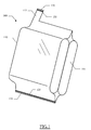
Figure 1 , anairtight bag 100 is shown. Thebag 100 is used for vacuum storing different articles, like ablanket 105. In the context of the present invention, the word vacuum is intended to denote a condition (more or less high) of rarefaction of the air (with a consequent pressure lower than the atmospheric one). - The
bag 100 consists of aflexible container 110. Thecontainer 110 is made of a material (for example, polythene) so as to guarantee its air-tightness; preferably, the material of thecontainer 110 exhibits a high adhesion, thereby facilitating the sealing of thebag 110 under the action of the depression created inside it (as described in detail in the following). Thecontainer 110 is provided with atubular projection 115 that extends upwards at a corner of thecontainer 110. - A main opening 120 (used to insert the
blanket 105 into the container 110) is realized along a lower edge of thecontainer 110. As described in detail in the following, thebag 100 is provided with ahermetic sealing system 125 for themain opening 120. - Another
opening 130 is realized in the same way along a free edge of thetubular projection 115; theopening 130 is used as a suction mouth to remove the air from the inside of the container 110 (with themain opening 120 sealed). Thebag 100 is provided with a furtherhermetic sealing system 135 for thesuction mouth 130. - In order to use the
bag 100 described above, theblanket 105 is inserted into the container 110 (through the main opening 120). Themain opening 120 is then hermetically sealed using thesystem 125. At this point, it is possible to remove the air from thecontainer 110 through the suction mouth 130 (for example, by means of a vacuum-cleaner). Thesuction mouth 130 is then hermetically sealed using thesystem 135. - Similar considerations apply if the bag has a different structure or it is used to preserve other articles (such as clothes, towels, and the like). In any case, the concepts of the present invention are also applicable when the container is made with equivalent materials (for example, polypropylene or PVC), when the suction mouth is placed in another position or it is made with an applied element, and the like.
- In a preferred embodiment of the present invention, as shown in
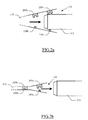
Figure 2a , the sealing system of thesuction mouth 130 consists of a double pressure zip (each one made of a pair of interlocking elements). Particularly, an external pressure zip includes atrack 205a and arib 210a (suitable to press-fit into thetrack 205a). The interlockingelements tubular projection 115, and they extend parallel to an edge of thesuction mouth 130. The interlockingelements track 205b and arib 210b; the interlockingelements elements - In order to create the desired vacuum condition into the container, a
pipe 215 of a vacuum-cleaner (not shown in the figure) is inserted into thesuction mouth 130. When the vacuum-cleaner is actuated, the air is removed from the container along the flux indicated by the arrow in the figure. - As shown in
Figure 2b , the resulting depression crushes thetubular projection 115. Therefore, therib 210b is pushed towards the correspondingtrack 205b; in this way, therib 210b fits into thetrack 205b tending to close theinternal pressure zip pipe 215 of the vacuum-cleaner is extracted from thetubular projection 115, also theexternal pressure zip tubular projection 115 by hand, so as to guarantee the complete closing of the pressure zips 205a,210a and 205b,210b. - The
internal pressure zip suction mouth 130. However, any leak of air through theinternal pressure zip external pressure zip - Similar considerations apply to the sealing system used for the main opening of the container.
- In any case, the concepts of the present invention are also applicable when the air is sucked from the bag in a different way (for example, using a dedicated machine in an industrial packaging process); alternatively, the sealing system can include a different number of pressure zips, or every pressure zip can be made in another way.
- Passing now to
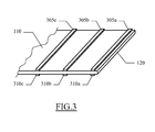
Figure 3 , in an alternative embodiment of the present invention, the sealing system of themain opening 120 of thecontainer 110 consists of three pairs of bi-adhesive strips (while the sealing system of the suction mouth again consists of the double pressure zip described above). Particularly, an external pair is formed by abi-adhesive strip 305a and abi-adhesive strip 310a (parallel to the edge of the main opening 120). Thebi-adhesive strips container 110 opposite to each other (with eachbi-adhesive strip bi-adhesive strip 305a and thebi-adhesive strip 310a are placed on an upper surface and on a lower surface, respectively, of the container 110 (so that they are opposite to each other). An internal pair is likewise formed by abi-adhesive strip 305b and abi-adhesive strip 310b; thebi-adhesive strips bi-adhesive strips bi-adhesive strip 305c and abi-adhesive strip 310c (placed at a far larger distance from the main opening 120). - A sequence of operations performed during the use of the bag described above is shown in
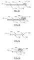
Figures 4a-4d . Considering in particularFigure 4a , the blanket is inserted into thecontainer 110 through themain opening 120. Themain opening 120 is sealed by removing the protective film of thebi-adhesive strip 305a and then folding up an edge of thecontainer 110 on itself (close to the main opening 120). As a consequence, thebi-adhesive strip 305a sticks on the upper surface of thecontainer 110, thereby fastening the folding so obtained. At the same time, thebi-adhesive strip 310a (opposite thebi-adhesive strip 305a) turns upwards. - With reference now to
Figure 4b , thecontainer 110 is folded again on itself (after removing the protective film of thebi-adhesive strip 310a). As a consequence, thebi-adhesive strip 310a sticks on the upper surface of thecontainer 110 and fastens the corresponding folding (which embeds the folding created beforehand). - The folding fastened by the
bi-adhesive strip 305a is generally enough to seal hermetically themain opening 120. However, any leak of air through this folding is intercepted by the further folding fastened by thebi-adhesive strip 310a (so as to guarantee the complete air-tightness of the bag). - The air is then removed from the container through the suction mouth, which is afterwards sealed hermetically as described above.
- Passing to
Figure 4c , if it is necessary to use the blanket stored in the bag thecontainer 110 is cut just inside the folding formed to seal its main opening; this cut creates a newmain opening 120n. The blanket is then extracted from thecontainer 110 through the new main opening 110n. - A different blanket (or any other article) can be inserted into the
container 110, thus hermetically sealing the newmain opening 120n. The sealing of the newmain opening 120n is performed repeating the same operations described above (using the next corresponding pair of bi-adhesive strips). Particularly, as shown inFigure 4d , the newmain opening 120n is sealed by means of a further folding fastened by thebi-adhesive strip 310b (which embeds the preceding folding). The air is then removed from the container through the suction mouth, which is afterwards sealed hermetically. - Similar considerations apply if the bi-adhesive strips of each pair are staggered among them, if a different number of pairs of bi-adhesive strips is provided, and the like. In any case, the bag according to the present invention leads itself to the made using the same sealing system based on the bi-adhesive strips for the suction mouth as well.
- A further embodiment of the invention is illustrated in
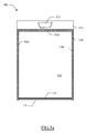
Figure 5a (the elements corresponding to the ones shown in theFigure 1 are denoted with the same references, and their explanation is omitted for the sake of brevity). The figure illustrates abag 500, which consists of acontainer 510. In this case, thecontainer 510 is only provided with the (main) opening 120, which is sealed by thedouble pressure zip 125; conversely, no distinct suction mouth is provided. - The
container 510 also has a weldedflap 515, which extends from anupper edge 520u (opposite the opening 120). Ahandle 525 is formed in the flap 515 (for example, through a cutting or punching operation). Particularly, the above-described structure is obtained by means of aweld 530, which extends along thisupper edge 520u and twoside edges opening 120 and the flap 515). - With reference to
Figure 5b , thebag 500 is used by inserting theblanket 105 into the container 510 (through the opening 120). Thepipe 215 of the vacuum-cleaner is inserted into aportion 120a of the opening 120 (which extends from its right end). A remainingportion 120p of the opening 120 (extending from its left end) is then sealed using thezip 125, so that theportion 120a defines a suction mouth. At this point, it is possible to remove the air from thecontainer 510 by actuating the vacuum-cleaner (not shown in the figure). As thepipe 215 of the vacuum-cleaner is extracted from theopening 120, the sealing of theopening 120 is completed by acting on thezip 125 corresponding to theportion 120a. - The
zip 125 is generally enough to maintain theportion 120p closed during the operation of sucking the air; for greater safety, however, it is possible to press thecontainer 510 so as to prevent any opening of theportion 120p. - Alternatively, as shown in
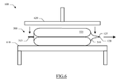
Figure 6 , the above-describedbag 500 leads itself to be used in anindustrial packaging system 600, which consists of a press (for example, of the pneumatic type). Thepress 600 is formed by astationary bearing base 610; amovable plate 620 is used to exercise a pressure on thebase 610. Once theblanket 105 has been inserted into thecontainer 510, thebag 500 is placed onto thebase 610. Theplate 620 is then lowered so as to crush thebag 500. The pressure exerted by theplate 620 quickly removes the air from the container 510 (and also from the blanket 105) through theopening 120. Thezip 125 then closes automatically, under the action of the depression created inside the container 510 (or through the application of an additional pressure). In this way, the volume of theblanket 105 is substantially reduced (for example, by more than 50%). - The above-described procedure is made possible by the fact that the
bag 500 lacks any valve (which would be broken off under the action of the press 600). Moreover, the single opening 120 (being wide and easy to seal) makes this procedure very fast. - Similar considerations apply if the bag has a different structure or it is used to store other articles; alternatively, the opening has a different shape, it is placed in another position, or it is sealed through equivalent means. In any case, the concepts of the present invention are also applicable when the press is of a different type or it has another structure.
- Although the present invention has been described above with a certain degree of particularity with reference to preferred embodiment(s) thereof, it should be understood that various omissions, substitutions and changes in the form and details as well as other embodiments are possible. Particularly, it is expressly intended that all combinations of those elements and/or method steps that substantially perform the same function in the same way to achieve the same results are within the scope of the invention. Moreover, it should be understood that specific elements and/or method steps described in connection with any disclosed embodiment of the invention may be incorporated in any other embodiment as a general matter of design choice. It will also be apparent to those skilled in the art that the additional features providing further advantages are not essential for carrying out the invention, and may be omitted or replaced with different features.
- For example, the bag of the present invention leads itself to be implemented also using the fast pressure sealing system for the suction mouth only. Alternatively, a single pressure zip is provided, or other fast pressure sealing systems are used (for example, Velcro strips).
- Alternatively, the suction mouth can be defined in the center of the main opening (which is closed at both sides of the area where the pipe of the vacuum-cleaner is inserted), or in whatever other position.
- In any case, the solution of the invention leads itself to be implemented using a different number of adhesive strips (down to a single one), or forming a single folding at every sealing. Besides, the adhesive strips can be placed all on the same surface, or they can also be formed directly on the container (for example, through a printing process).
- In addition, the implementation of the bag with a different handle or even without any hook is not excluded.
- It should also be noted that the implementation of the bag with a single opening (i.e., without the suction mouth) is also possible with different means for sealing this opening hermetically, even not of the pressure type (although its use is less practical).
- Naturally, in order to satisfy local and specific requirements, a person skilled in the art may apply to the solution described above many modifications and alterations all of which, however, are included within the scope of protection of the invention as defined by the following claims.
Claims (15)
- An airtight bag (500) for vacuum storing an article (105), the bag including a container (510) having a main opening (120) for inserting the article into the container, sealing means (125) for hermetically sealing the main opening, and a suction opening for removing air from the container to create a substantial vacuum condition in the container,
characterized in that
the suction opening consists of at least a portion (120a;120) of the main opening. - The bag (500) according to claim 1, wherein the suction opening consists of a first portion (120a) of the main opening (120), the first portion having a variable extension defined by sealing a remaining second portion (120p) of the main opening with the sealing means (125).
- The bag (500) according to claim 2, wherein the first portion (120a) and the second portion (120p) extend from a first end and from a second end, respectively, of the main opening (120).
- The bag (500) according to claim 1, wherein the suction opening consists of the whole main opening (120).
- The bag (500) according to any claim from 1 to 4, wherein the sealing means (125) includes fast pressure sealing means.
- The bag (500) according to claim 5, wherein the fast pressure sealing means (125) includes at least one pressure zip (205a-205,210a-210b).
- The bag (500) according to claim 6, wherein the at least one pressure zip consists of a plurality of pressure zips (205a-205,210a-210b) arranged parallel to the main opening (120).
- The bag (500) according to any claim from 1 to 7, wherein the sealing means (125) includes at least one adhesive strip (305a-305c,310a-310c) for fastening a corresponding folding of the container (110).
- The bag (500) according to claim 8, wherein the at least one adhesive strip consists of at least one pair of adhesive strips (305a-310a,305b-310b,305c-310c) each one formed by a first strip (305a-305c) attached to a first outer surface of the container (110) for fastening a first folding of the container and a second strip (310a-310c) attached to a second outer surface of the container opposite the first surface for fastening a second folding of the container embedding the first strip.
- The bag (500) according to any claim from 1 to 9, wherein the container (510) includes a flap (515) opposite the main opening (120), a handle (525) for the bag being formed in said flap.
- A method for vacuum storing an article (105) in an airtight bag (500), the method including the steps of:inserting the article into a container (510) of the bag through a main opening (120) of the container,removing air from the container to create a substantial vacuum condition in the container, andhermetically sealing the main opening,characterized in that
the step of removing air includes:removing the air through at least a portion (120a;120) of the main opening. - The method according to claim 11, wherein the step of removing air includes:creating a suction opening as a first portion (120a) of the main opening (120), the first portion having a variable extension defined by sealing a remaining second portion (120p) of the main opening, andremoving the air through the suction opening.
- The method according to claim 12, wherein the step of removing air includes:inserting a pipe (215) of a vacuum-cleaner into the main opening (120) before creating the suction opening (120a), andactuating the vacuum-cleaner to remove the air through the suction opening.
- The method according to claim 11, wherein the step of removing air includes:removing the air through the whole main opening (120).
- The method according to claim 14, wherein the step of removing the air through the whole main opening (120) includes:pressing the container (510) with a press (620).
Applications Claiming Priority (3)
| Application Number | Priority Date | Filing Date | Title |
|---|---|---|---|
| ITMI20031895 | 2003-10-03 | ||
| ITMI20040280 ITMI20040280A1 (en) | 2004-02-19 | 2004-02-19 | AIR-SEALING BAG WITH IMPROVED CLOSING SYSTEM |
| EP20040104699 EP1520801B1 (en) | 2003-10-03 | 2004-09-27 | An airtight bag for vacuum storing an article |
Related Parent Applications (1)
| Application Number | Title | Priority Date | Filing Date |
|---|---|---|---|
| EP20040104699 Division EP1520801B1 (en) | 2003-10-03 | 2004-09-27 | An airtight bag for vacuum storing an article |
Publications (1)
| Publication Number | Publication Date |
|---|---|
| EP1982927A1 true EP1982927A1 (en) | 2008-10-22 |
Family
ID=34315477
Family Applications (2)
| Application Number | Title | Priority Date | Filing Date |
|---|---|---|---|
| EP20040104699 Expired - Fee Related EP1520801B1 (en) | 2003-10-03 | 2004-09-27 | An airtight bag for vacuum storing an article |
| EP08104302A Withdrawn EP1982927A1 (en) | 2003-10-03 | 2004-09-27 | An airtight bag with single opening |
Family Applications Before (1)
| Application Number | Title | Priority Date | Filing Date |
|---|---|---|---|
| EP20040104699 Expired - Fee Related EP1520801B1 (en) | 2003-10-03 | 2004-09-27 | An airtight bag for vacuum storing an article |
Country Status (2)
| Country | Link |
|---|---|
| EP (2) | EP1520801B1 (en) |
| DE (1) | DE602004017687D1 (en) |
Families Citing this family (1)
| Publication number | Priority date | Publication date | Assignee | Title |
|---|---|---|---|---|
| WO2007131273A1 (en) * | 2006-05-11 | 2007-11-22 | Mark Amit Robinson | Vacuum stabilized carry bag |
Citations (7)
| Publication number | Priority date | Publication date | Assignee | Title |
|---|---|---|---|---|
| DE2036432A1 (en) * | 1969-08-14 | 1971-02-25 | Kabushiki Kaisha Seisan Nipponsha, Tokio | Airtight bag with detachable closure |
| GB2250011A (en) * | 1990-11-21 | 1992-05-27 | Decoflex Ltd | Bag with reinforced handle |
| US5701996A (en) * | 1994-05-17 | 1997-12-30 | Idemitsu Petrochemical Co., Ltd. | Snap-fastener bag |
| EP0827912A2 (en) * | 1996-09-06 | 1998-03-11 | Fres-Co System Usa, Inc. | Resealable package |
| US6045264A (en) * | 1998-01-29 | 2000-04-04 | Miniea; Stephen H. | Self-sealing, disposable storage bag |
| US6085906A (en) * | 1998-12-18 | 2000-07-11 | Lambert; Francis | Vacuum sealing system |
| US20030183550A1 (en) * | 2002-03-26 | 2003-10-02 | Diliberto Samuel L. | Disaster pack and method for making same |
Family Cites Families (5)
| Publication number | Priority date | Publication date | Assignee | Title |
|---|---|---|---|---|
| US2225810A (en) * | 1937-05-15 | 1940-12-24 | Harry F Waters | Packaging method |
| CA2054114C (en) * | 1990-11-05 | 2003-03-25 | Todd Steven Marnocha | Multi-seal recloseable flexible package |
| US5240112A (en) * | 1992-02-25 | 1993-08-31 | Newburger Bronson E | Evacuatable or inflatable plastic bag |
| CA2086477A1 (en) * | 1992-08-03 | 1994-02-04 | Donald B. Moore, Jr. | Shrink bag with integral handle |
| JP2003072855A (en) * | 2001-08-27 | 2003-03-12 | Ishizaki Shizai Kk | Deaeration bag having suction nozzle, suction nozzle, and deaeration bag |
-
2004
- 2004-09-27 EP EP20040104699 patent/EP1520801B1/en not_active Expired - Fee Related
- 2004-09-27 EP EP08104302A patent/EP1982927A1/en not_active Withdrawn
- 2004-09-27 DE DE200460017687 patent/DE602004017687D1/en active Active
Patent Citations (7)
| Publication number | Priority date | Publication date | Assignee | Title |
|---|---|---|---|---|
| DE2036432A1 (en) * | 1969-08-14 | 1971-02-25 | Kabushiki Kaisha Seisan Nipponsha, Tokio | Airtight bag with detachable closure |
| GB2250011A (en) * | 1990-11-21 | 1992-05-27 | Decoflex Ltd | Bag with reinforced handle |
| US5701996A (en) * | 1994-05-17 | 1997-12-30 | Idemitsu Petrochemical Co., Ltd. | Snap-fastener bag |
| EP0827912A2 (en) * | 1996-09-06 | 1998-03-11 | Fres-Co System Usa, Inc. | Resealable package |
| US6045264A (en) * | 1998-01-29 | 2000-04-04 | Miniea; Stephen H. | Self-sealing, disposable storage bag |
| US6085906A (en) * | 1998-12-18 | 2000-07-11 | Lambert; Francis | Vacuum sealing system |
| US20030183550A1 (en) * | 2002-03-26 | 2003-10-02 | Diliberto Samuel L. | Disaster pack and method for making same |
Also Published As
| Publication number | Publication date |
|---|---|
| DE602004017687D1 (en) | 2008-12-24 |
| EP1520801A1 (en) | 2005-04-06 |
| EP1520801B1 (en) | 2008-11-12 |
Similar Documents
| Publication | Publication Date | Title |
|---|---|---|
| US6986605B1 (en) | Multiwall vented bag, vented bag forming apparatus, and associated methods | |
| US5333736A (en) | Self-sealing compression packaging bag and compression packaging bag | |
| US6021624A (en) | Vented pouch arrangement and method | |
| US6085906A (en) | Vacuum sealing system | |
| US5059036A (en) | Vented pouch arrangement and method | |
| AU2001274878B2 (en) | Reclosable bag | |
| US5147272A (en) | Method of making a vented pouch | |
| US7524110B2 (en) | Reclosable package with slider zipper shielded for high pressure pasteurization | |
| EP0626312B1 (en) | Method and apparatus for making a vacuum package filled with granular material | |
| CN100465071C (en) | Apparatus and method for vacuum packing products | |
| US20030219177A1 (en) | Bag for vacuum packaging | |
| EP1520801B1 (en) | An airtight bag for vacuum storing an article | |
| CA2345510C (en) | Bag for automated filling and sealing machine | |
| WO2007027425A1 (en) | Method of forming and using a vented bag | |
| US7223222B2 (en) | Slider zipper assembly and shroud with high pressure pasteurization protection system | |
| CN106275577A (en) | A kind of package sealing machine and packaging bag enclosing method | |
| WO1992022474A1 (en) | Improvements relating to the packaging of tea | |
| JPH06263117A (en) | Packaging method with inside air let out of bag in vertical bag-forming, filling and packaging method | |
| JPH0551040A (en) | Packaging bag | |
| EP4082399A1 (en) | Method of packing a mattress | |
| CA1082142A (en) | Seal for self-welding bag | |
| EP0250149A1 (en) | Improvements in or relating to seals | |
| JP2515561Y2 (en) | Vacuum compression sealed bag | |
| JP3092768U (en) | Apparatus for continuously forming vacuum packages | |
| US20010054274A1 (en) | Bag for automated filling and sealing machine |
Legal Events
| Date | Code | Title | Description |
|---|---|---|---|
| PUAI | Public reference made under article 153(3) epc to a published international application that has entered the european phase |
Free format text: ORIGINAL CODE: 0009012 |
|
| AC | Divisional application: reference to earlier application |
Ref document number: 1520801 Country of ref document: EP Kind code of ref document: P |
|
| AK | Designated contracting states |
Kind code of ref document: A1 Designated state(s): DE ES FR GB IT |
|
| 17P | Request for examination filed |
Effective date: 20090422 |
|
| AKX | Designation fees paid |
Designated state(s): DE ES FR GB IT |
|
| 17Q | First examination report despatched |
Effective date: 20090921 |
|
| RAP1 | Party data changed (applicant data changed or rights of an application transferred) |
Owner name: SALDOPLAST S.R.L. |
|
| STAA | Information on the status of an ep patent application or granted ep patent |
Free format text: STATUS: THE APPLICATION IS DEEMED TO BE WITHDRAWN |
|
| 18D | Application deemed to be withdrawn |
Effective date: 20130403 |