EP1988408A1 - Positioning system, positioning method and car navigation system - Google Patents
Positioning system, positioning method and car navigation system Download PDFInfo
- Publication number
- EP1988408A1 EP1988408A1 EP07714276A EP07714276A EP1988408A1 EP 1988408 A1 EP1988408 A1 EP 1988408A1 EP 07714276 A EP07714276 A EP 07714276A EP 07714276 A EP07714276 A EP 07714276A EP 1988408 A1 EP1988408 A1 EP 1988408A1
- Authority
- EP
- European Patent Office
- Prior art keywords
- navigation
- unit
- positioning
- point
- satellite
- Prior art date
- Legal status (The legal status is an assumption and is not a legal conclusion. Google has not performed a legal analysis and makes no representation as to the accuracy of the status listed.)
- Granted
Links
- 238000000034 method Methods 0.000 title claims description 17
- 238000012937 correction Methods 0.000 claims description 12
- 238000010586 diagram Methods 0.000 description 2
- 238000012545 processing Methods 0.000 description 2
- 230000001755 vocal effect Effects 0.000 description 2
- 230000005540 biological transmission Effects 0.000 description 1
- 230000007423 decrease Effects 0.000 description 1
- 238000001514 detection method Methods 0.000 description 1
- 238000006073 displacement reaction Methods 0.000 description 1
- 230000000694 effects Effects 0.000 description 1
- 230000004907 flux Effects 0.000 description 1
- 239000004973 liquid crystal related substance Substances 0.000 description 1
- 238000013507 mapping Methods 0.000 description 1
- 238000005259 measurement Methods 0.000 description 1
- 238000012986 modification Methods 0.000 description 1
- 230000004048 modification Effects 0.000 description 1
- 230000001360 synchronised effect Effects 0.000 description 1
Images


Classifications
-
- G—PHYSICS
- G01—MEASURING; TESTING
- G01C—MEASURING DISTANCES, LEVELS OR BEARINGS; SURVEYING; NAVIGATION; GYROSCOPIC INSTRUMENTS; PHOTOGRAMMETRY OR VIDEOGRAMMETRY
- G01C21/00—Navigation; Navigational instruments not provided for in groups G01C1/00 - G01C19/00
- G01C21/26—Navigation; Navigational instruments not provided for in groups G01C1/00 - G01C19/00 specially adapted for navigation in a road network
- G01C21/28—Navigation; Navigational instruments not provided for in groups G01C1/00 - G01C19/00 specially adapted for navigation in a road network with correlation of data from several navigational instruments
-
- G—PHYSICS
- G01—MEASURING; TESTING
- G01S—RADIO DIRECTION-FINDING; RADIO NAVIGATION; DETERMINING DISTANCE OR VELOCITY BY USE OF RADIO WAVES; LOCATING OR PRESENCE-DETECTING BY USE OF THE REFLECTION OR RERADIATION OF RADIO WAVES; ANALOGOUS ARRANGEMENTS USING OTHER WAVES
- G01S19/00—Satellite radio beacon positioning systems; Determining position, velocity or attitude using signals transmitted by such systems
- G01S19/38—Determining a navigation solution using signals transmitted by a satellite radio beacon positioning system
- G01S19/39—Determining a navigation solution using signals transmitted by a satellite radio beacon positioning system the satellite radio beacon positioning system transmitting time-stamped messages, e.g. GPS [Global Positioning System], GLONASS [Global Orbiting Navigation Satellite System] or GALILEO
- G01S19/42—Determining position
- G01S19/48—Determining position by combining or switching between position solutions derived from the satellite radio beacon positioning system and position solutions derived from a further system
- G01S19/49—Determining position by combining or switching between position solutions derived from the satellite radio beacon positioning system and position solutions derived from a further system whereby the further system is an inertial position system, e.g. loosely-coupled
Definitions
- the present invention generally relates to a positioning system, a positioning method, and a car navigation system for estimating the current position of a mobile body based on radio signals from multiple radio stations such as global positioning system (GPS) satellites. More particularly, the present invention relates to a positioning system, a positioning method, and a car navigation system that can accurately estimate the current position of a mobile body even when radio signals are not available from a sufficient number of radio stations.
- GPS global positioning system
- GPS devices used to detect the current position of a vehicle and to show the user a route to a destination.
- a GPS device installed in a vehicle receives a carrier wave modulated by a pseudorandom code from a GPS satellite and calculates the distance from the GPS satellite by multiplying light velocity and propagation time of the carrier wave obtained in the demodulation process.
- the position of a vehicle on the Earth is determined in a three-dimensional space defined by latitude, longitude, and altitude (hereafter, these are simply called coordinates). Therefore, a GPS device receives times of origin from three GPS satellites and obtains the coordinates of the vehicle by calculating an intersection point of spheres each having a radius that is the distance between the vehicle and the corresponding one of the three GPS satellites.
- a GPS device normally uses a fourth GPS satellite to correct a time error and thereby to accurately detect the position of a vehicle.
- the GPS device may not always be able to receive radio signals carrying times of origin from all four GPS satellites.
- the current position of a vehicle is estimated by autonomous navigation and/or a map matching method when radio signals from GPS satellites are not available.
- the accuracy of the estimated position decreases if GPS satellite signals are not available for a long time.
- Patent document 1 discloses a method that enables detection of the position of a vehicle even when a radio signal is only available from one GPS satellite.
- a circle supposedly including the current position of a vehicle is calculated based on a radio signal from a GPS satellite.
- a current travel direction of the vehicle is obtained by updating the direction of the vehicle with, for example, a gyro sensor.
- the current position of the vehicle is obtained by calculating an intersection point of the circle and the current travel direction.
- Patent document 1 Japanese Patent Application Publication No. 8-75479
- Embodiments of the present invention provide a positioning system and a car navigation system that solve or reduce one or more problems caused by the limitations and disadvantages of the related art and that can accurately estimate the position of a mobile body even when radio signals are not available from a sufficient number of GPS satellites.
- An embodiment of the present invention provides a positioning system including a positioning unit configured to perform position estimation based on radio signals from artificial satellites; and an autonomous navigation unit (e.g., INS unit 14) configured to perform position estimation by autonomous navigation.
- the positioning unit and the autonomous navigation unit estimate a position of a mobile body in cooperation with each other; and when the number of the artificial satellites available is less than three, the positioning unit determines a point in an area calculated based on the radio signals which point is closest to an inertial-navigation-based position calculated by the autonomous navigation and uses the determined point as a satellite-based position estimated based on the radio signals.
- the area when the number of the artificial satellites available is one, the area is defined as a sphere, with every point on the sphere being at an equal distance from the one of the artificial satellites; and when the number of the artificial satellites available is two, the area is defined as a curved line where two spheres intersect, with every point on each of the two spheres being at an equal distance from the corresponding one of the two of the artificial satellites.
- This configuration makes it possible to determine a satellite-based position on a sphere or a curved line.
- the satellite-based position is corrected based on the inertial-navigation-based position calculated by autonomous navigation to estimate the position of the mobile body.
- This configuration makes it possible to estimate the position of a mobile body by correcting a satellite-based position based on an inertial-navigation-based position calculated by autonomous navigation even when the number of GPS satellites available is insufficient.
- Embodiments of the present invention provide a positioning system and a car navigation system that can accurately estimate the position of a mobile body even when radio signals are not available from a sufficient number of GPS satellites.
- FIG. 1 is a block diagram illustrating a configuration of a car navigation system 1 including a positioning system 10 according to an embodiment of the present invention.
- the car navigation system 1 provides various services to the driver. For example, the car navigation system 1 displays the current position of a vehicle detected by the positioning system 10 on a map or shows a route to a destination based on the detected position.
- a car navigation ECU 19 retrieves a road map from a map database 20 based on the current position of a vehicle estimated as described later and displays the retrieved road map on an output unit 18.
- the output unit 18 is, for example, implemented by a liquid crystal display (LCD), an organic light emitting diode (OLED) display, or a heads-up display (HUD).
- the output unit 18 is connected to a speaker (not shown) for outputting audio guidance, for example, on the route at an intersection.
- An input unit 17 is implemented, for example, by a keyboard, buttons, a remote control, an arrow key, or a touch panel, and is used by the driver as an interface for inputting commands.
- the car navigation system 1 may also include a microphone for inputting vocal commands and a voice recognition circuit for processing the vocal commands.
- the driver When searching for a route to a destination, the driver specifies the destination, for example, with an address, a place name, a landmark name, or a postal code.
- the car navigation system 1 may further include a TV, a radio, and a media player for playing recording media such as a DVD, which are operated by the input unit 17.
- the map database 20 is, for example, stored in a hard disk, a CD-ROM, or a DVD-ROM, and contains road map data defining roads and intersections in relation to latitude and longitude.
- the map database 20 is a tabular database containing road map data where an actual road network is represented by nodes (intersections of roads) and links (roads connecting the nodes).
- a node table in the map database 20 contains, for each node, a node number, coordinates, the number of links extending from the node, and link numbers of the links.
- a link table contains, for each link, a link number, an initial node and a terminal node of the link, and a link length. Node numbers and link numbers are determined so as not to overlap each other. Thus, a road network can be traced by following the node numbers and the link numbers.
- the positioning system 10 includes a GPS receiver 11 for receiving radio signals from GPS satellites, an inertial navigation system (INS) unit 14 for estimating the position of a vehicle by autonomous navigation, a positioning unit 15 for estimating the position of a vehicle based on radio signals from GPS satellites and on the position estimated by the INS unit 14, and an estimation unit 16 that calculates a correction value by estimating an error in the position estimated by the positioning unit 15.
- INS inertial navigation system
- the positioning system 10 combines a position calculated based on radio signals from GPS satellites and a position calculated by the INS unit 14 to estimate the most probable position of a vehicle.
- GPS satellites e.g., 24 GPS satellites
- multiple orbits e.g., 6 orbits
- Approximate orbits of GPS satellites are known and more precise orbits can be obtained from ephemerides in navigation messages transmitted from the GPS satellites.
- the GPS receiver 11 Based on the obtained orbits of GPS satellites, the GPS receiver 11 selects preferably four or more GPS satellites within a predetermined elevation angle from the current position of a vehicle, and receives radio signals from the selected GPS satellites.
- Each GPS satellite sends a radio signal generated by modulating a carrier wave L1 having a frequency of 1575.42 MHz with a coarse/acquisition (C/A) code assigned to the GPS satellite.
- the GPS receiver 11 generates the C/A code for each selected GPS satellite and tries to demodulate the radio signal from the GPS satellite.
- a C/A code is composed of 1023 bits of "1" and "0".
- the carrier wave L1 is modulated repeatedly by the C/A code.
- the GPS receiver 11 adjusts the phase ("1" or "0") of 1023 bits of the generated C/A code in order to demodulate the radio signal, in other words, to capture the radio signal from the GPS satellite.
- the phase of the C/A code of the carrier wave L1 generated by the GPS satellite and demodulated by the positioning system 10 are shifted by an amount corresponding to the travel time of the radio signal.
- the positioning unit 15 calculates the travel time of the radio signal based on the amount of shift, and obtains the distance from the GPS satellite based on the calculated travel time and the speed of light c.
- FIG. 2 is a drawing illustrating a relationship between a vehicle and GPS satellites St1 to St4.
- the positioning unit 15 sets up simultaneous equations as described below, solves the equations for variables (X, Y, and Z), and thereby obtains latitude X, longitude Y, and altitude Z of a vehicle (hereafter, coordinates of a vehicle estimated based on GPS satellite signals are called satellite-based coordinates).
- X1, Y1, and Z1 indicate coordinates of the GPS satellite St1; X2, Y2, and Z2 indicate coordinates of the GPS satellite St2; and X3, Y3, and Z3 indicate coordinates of the GPS satellite St3.
- the coordinates of the GPS satellites St1 to St3 can be obtained from their ephemerides. Therefore, the position of a vehicle, or three variables, can be obtained by using three GPS satellites. Solving the simultaneous equations is to obtain an intersection point of surfaces of three spheres each having a GPS satellite at its center, which intersection point is used as the satellite-based coordinates of a vehicle.
- the relative velocity of the vehicle with respect to each GPS satellite can be obtained by differentiating the distance ⁇ of the GPS satellite with time, and the speed of the vehicle can be obtained from the relative velocity.
- the speed of a vehicle may be obtained based on the Doppler shift of the carrier wave L1.
- the Doppler shift is proportional to the difference between the speed of a vehicle and the speed of a GPS satellite. Therefore, the speed of a vehicle can be obtained based on the known speed of a GPS satellite and the Doppler shift.
- the Doppler shift can be calculated based on the change in the frequency of the carrier wave L1.
- an embodiment of the present invention provides a positioning system that can accurately estimate the position of a vehicle even when less than three GPS satellites are available.
- the coordinates obtained from the above simultaneous equations are based on a reference frame called the world geodetic system (WGS).
- the positioning unit 15 converts the obtained coordinates into the earth-fixed orthogonal coordinate system.
- the position of a vehicle represented by the converted coordinates is called a satellite-based position.
- the positioning unit 15 is connected to a speed sensor 12 and a gyro sensor 13 of the INS unit 14.
- the speed sensor 12 detects pulses, i.e., changes in magnetic flux caused when protrusions, which are disposed at regular intervals along the circumference of a rotor of each wheel, pass through a detector, and measures the speed of the vehicle based on the number of pulses per unit time.
- the gyro sensor 13 is a yaw rate sensor, such as a fiber-optic gyroscope or a vibratory gyroscope, that detects the angular speed of the rotation of a vehicle and obtains the angle or the traveling direction of the vehicle by integrating the detected angular speed.
- the gyro sensor 13 is preferably capable of detecting a three-axis direction or a three-dimensional direction of a vehicle.
- the INS unit 14 estimates the current position of a vehicle by autonomous navigation, i.e., by updating the satellite-based position of the vehicle based on the travel distance obtained by the speed sensor 12 and the traveling direction obtained by the gyro sensor 13 (hereafter, the position of a vehicle estimated by autonomous navigation is called an inertial-navigation-based position).
- the positioning unit 15 can estimate the current position of a vehicle based on the speed and direction of the vehicle detected by the INS unit 14 by autonomous navigation even when no radio signal is available from GPS satellites.
- the satellite-based position and the inertial-navigation-based position are input into the estimation unit 16. Based on the input positions and previously detected positions, the estimation unit 16 estimates errors in the input positions and thereby calculates a correction value for the inertial-navigation-based position.
- the correction value for the inertial-navigation-based position is input into the INS unit 14.
- the INS unit 14 corrects the inertial-navigation-based position with the correction value and outputs the corrected inertial-navigation-based position to the positioning unit 15.
- the estimation unit 16 calculates the correction value for the inertial-navigation-based position using, for example, the Kalman filter.
- the Kalman filter is an algorithm that estimates a most provable value from a measured value(s) including noise.
- the Kalman filter calculates a correction value so as to minimize the mean square error of an estimate obtained by processing inertial-navigation-based positions input in succession.
- the INS unit 14 accurately corrects the inertial-navigation-based position and outputs the corrected inertial-navigation-based position to the positioning unit 15.
- the estimation unit 16 may be configured to estimate an error in the inertial-navigation-based position based on the input satellite-based position.
- the estimation unit 16 may be configured to correct the satellite-based position based on atmospheric conditions and/or the elevation angle when four or more GPS satellites are available, and to estimate an error in the inertial-navigation-based position estimated by the INS unit 14 based on the corrected satellite-based position.
- the estimation unit 16 is configured not to estimate an error in the satellite-based position, or configured to estimate an error in the satellite-based position but not to input a correction value for the satellite-based position to the positioning unit 15.
- the Kalman filter is designed to estimate an error based on the tendency of previous measurements, and is therefore not suitable to estimate an error in the satellite-based position that is an instantaneously detected value. For example, if radio signals from GPS satellites are displaced greatly because of, for example, multipath transmission, the Kalman filter has to calculate correction values based on a satellite-based position having a large error for a substantial period of time after the displacement occurs. Therefore, in terms of accuracy of the satellite-based position, it is preferable not to correct the satellite-based position using a correction value obtained by the Kalman filter.
- the position of a vehicle can be accurately estimated by obtaining a satellite-based position of the vehicle in a three-dimensional space based on radio signals from the GPS satellites and by correcting the obtained satellite-based position by autonomous navigation provided by the INS unit 14.
- FIG. 3A is a drawing illustrating an area that can be identified when one GPS satellite is available
- FIG. 3B is a drawing illustrating an area that can be identified when two GPS satellites are available.
- the positioning system 10 of this embodiment determines a point in an area (defined as a sphere or a curved line) calculated based on the radio signals which point is closest to an inertial-navigation-based position obtained by autonomous navigation, and uses the determined point as a satellite-based position.
- the GPS receiver 11 tries to receive radio signals from GPS satellites (S1). If no GPS satellite is available, autonomous navigation by the INS unit 14 is continued.
- the positioning unit 15 compares the number of available GPS satellites and the number of variables necessary to calculate the position of a vehicle by the simultaneous equations described above (S2). As described above, four variables are necessary to correct even the time error of a clock, and three variables are necessary when the time error of a clock is corrected by a different method. In this embodiment, it is assumed that the number of variables is three. If the number of available GPS satellites is less than three, the process goes to step S3; and if the number of available GPS satellites is three or more, the process goes to step 4.
- the positioning unit 15 calculates a satellite-based position based on distances from the three or more GPS satellites (S4).
- the positioning unit 15 determines a position on a sphere or a curved line as shown in FIGS. 3A and 3B which position is closest to an inertial-navigation-based position obtained by the INS unit 14, and uses the determined position as a satellite-based position (S3).
- the positioning unit 15 corrects the satellite-based position with the inertial-navigation-based position as in a normal position estimating process, and thereby estimates the position of the vehicle (S5).
- the positioning unit 15 may be configured to more accurately determine the position of a vehicle by mapping the estimated position of the vehicle onto a road map in the map database 20.
- the estimated position of the vehicle is sent to the car navigation ECU 19.
- the estimation unit 16 estimates a true value of the inertial-navigation-based position and feeds back a correction value for the inertial-navigation-based position to the INS unit 14 (S6).
- a positioning system selects a satellite-based position closest to an inertial-navigation-based position from possible satellite-based positions defined as a sphere or a curved line, corrects the selected satellite-based position by autonomous navigation, and thereby estimates the position of a vehicle.
- This configuration makes it possible to accurately estimate the position of a vehicle even when only one or two GPS satellites are available.
- the inertial-navigation-based position is corrected by the estimation unit 16. This configuration further improves the accuracy of the selected satellite-based position that is closest to the inertial-navigation-based position.
- the present invention may also be applied to a positioning system for estimating the position of other mobile bodies such as a ship and an aircraft. Further, although GPS satellites are used as radio stations in the above embodiments, radio stations on the ground may also be used.
Abstract
Description
- The present invention generally relates to a positioning system, a positioning method, and a car navigation system for estimating the current position of a mobile body based on radio signals from multiple radio stations such as global positioning system (GPS) satellites. More particularly, the present invention relates to a positioning system, a positioning method, and a car navigation system that can accurately estimate the current position of a mobile body even when radio signals are not available from a sufficient number of radio stations.
- There are GPS devices used to detect the current position of a vehicle and to show the user a route to a destination. A GPS device installed in a vehicle receives a carrier wave modulated by a pseudorandom code from a GPS satellite and calculates the distance from the GPS satellite by multiplying light velocity and propagation time of the carrier wave obtained in the demodulation process. The position of a vehicle on the Earth is determined in a three-dimensional space defined by latitude, longitude, and altitude (hereafter, these are simply called coordinates). Therefore, a GPS device receives times of origin from three GPS satellites and obtains the coordinates of the vehicle by calculating an intersection point of spheres each having a radius that is the distance between the vehicle and the corresponding one of the three GPS satellites. Meanwhile, although a GPS satellite is equipped with an extremely high-precision clock, a clock in a vehicle is less precise. Therefore, the obtained propagation time necessarily includes an error and the calculated distance from the GPS satellite becomes inaccurate. To solve or reduce this problem, a GPS device normally uses a fourth GPS satellite to correct a time error and thereby to accurately detect the position of a vehicle.
- However, in the case of a GPS device installed in a mobile body such as a vehicle, the GPS device may not always be able to receive radio signals carrying times of origin from all four GPS satellites. In an in-vehicle positioning system, the current position of a vehicle is estimated by autonomous navigation and/or a map matching method when radio signals from GPS satellites are not available. However, the accuracy of the estimated position decreases if GPS satellite signals are not available for a long time.
-
Patent document 1 discloses a method that enables detection of the position of a vehicle even when a radio signal is only available from one GPS satellite. In the disclosed method, a circle supposedly including the current position of a vehicle is calculated based on a radio signal from a GPS satellite. Also, a current travel direction of the vehicle is obtained by updating the direction of the vehicle with, for example, a gyro sensor. The current position of the vehicle is obtained by calculating an intersection point of the circle and the current travel direction. - [Patent document 1] Japanese Patent Application Publication No.
8-75479 - When a radio signal is only available from one GPS satellite, it is only possible to determine that a vehicle is at a certain position on a sphere, with every point on the sphere at an equal distance from the GPS satellite. In this case, if the altitude of the Earth's surface is known, the current position of the vehicle can be obtained by calculating an intersection line of the sphere and the Earth's surface and by calculating an intersection point of the intersection line and the travel direction of the vehicle. However, because the altitude varies from point to point on the Earth's surface, the method disclosed in
patent document 1 can be used only if the altitude is known or fixed to be a predetermined value. In other words, with the disclosed method, it is not possible to accurately detect the position of a vehicle without a precise altitude. - Embodiments of the present invention provide a positioning system and a car navigation system that solve or reduce one or more problems caused by the limitations and disadvantages of the related art and that can accurately estimate the position of a mobile body even when radio signals are not available from a sufficient number of GPS satellites.
- An embodiment of the present invention provides a positioning system including a positioning unit configured to perform position estimation based on radio signals from artificial satellites; and an autonomous navigation unit (e.g., INS unit 14) configured to perform position estimation by autonomous navigation. In the positioning system, the positioning unit and the autonomous navigation unit estimate a position of a mobile body in cooperation with each other; and when the number of the artificial satellites available is less than three, the positioning unit determines a point in an area calculated based on the radio signals which point is closest to an inertial-navigation-based position calculated by the autonomous navigation and uses the determined point as a satellite-based position estimated based on the radio signals.
- With this configuration, because a point closest to an inertial-navigation-based position is used as a satellite-based position, it is possible to accurately estimate the position of a vehicle even when the number of GPS satellites available is insufficient.
- According to another embodiment of the present invention, when the number of the artificial satellites available is one, the area is defined as a sphere, with every point on the sphere being at an equal distance from the one of the artificial satellites; and when the number of the artificial satellites available is two, the area is defined as a curved line where two spheres intersect, with every point on each of the two spheres being at an equal distance from the corresponding one of the two of the artificial satellites.
- This configuration makes it possible to determine a satellite-based position on a sphere or a curved line.
- According to still another embodiment of the present invention, the satellite-based position is corrected based on the inertial-navigation-based position calculated by autonomous navigation to estimate the position of the mobile body.
- This configuration makes it possible to estimate the position of a mobile body by correcting a satellite-based position based on an inertial-navigation-based position calculated by autonomous navigation even when the number of GPS satellites available is insufficient.
- Embodiments of the present invention provide a positioning system and a car navigation system that can accurately estimate the position of a mobile body even when radio signals are not available from a sufficient number of GPS satellites.
-
-
FIG. 1 is a block diagram illustrating a configuration of a car navigation system including a positioning system; -
FIG. 2 is a drawing illustrating a relationship between a vehicle and GPS satellites St1 to St4; -
FIG. 3A is a drawing illustrating an area that can be identified when one GPS satellite is available, andFIG. 3B is a drawing illustrating an area that can be identified when two GPS satellites are available; and -
FIG. 4 is a flowchart showing an exemplary process of estimating the position of a vehicle by a positioning system. -
- 1
- Car navigation system
- 10
- Positioning system
- 11
- GPS receiver
- 12
- Speed sensor
- 13
- Gyro sensor
- 14
- INS unit
- 15
- Positioning unit
- 16
- Estimation unit
- 17
- Input unit
- 18
- Output unit
- 19
- Car navigation ECU
- 20
- Map database
- The best mode for carrying out the invention is described based on the following embodiments with reference to the accompanying drawings.
FIG. 1 is a block diagram illustrating a configuration of acar navigation system 1 including apositioning system 10 according to an embodiment of the present invention. Thecar navigation system 1 provides various services to the driver. For example, thecar navigation system 1 displays the current position of a vehicle detected by thepositioning system 10 on a map or shows a route to a destination based on the detected position. - A
car navigation ECU 19 retrieves a road map from amap database 20 based on the current position of a vehicle estimated as described later and displays the retrieved road map on anoutput unit 18. Theoutput unit 18 is, for example, implemented by a liquid crystal display (LCD), an organic light emitting diode (OLED) display, or a heads-up display (HUD). Theoutput unit 18 is connected to a speaker (not shown) for outputting audio guidance, for example, on the route at an intersection. - An
input unit 17 is implemented, for example, by a keyboard, buttons, a remote control, an arrow key, or a touch panel, and is used by the driver as an interface for inputting commands. Thecar navigation system 1 may also include a microphone for inputting vocal commands and a voice recognition circuit for processing the vocal commands. When searching for a route to a destination, the driver specifies the destination, for example, with an address, a place name, a landmark name, or a postal code. - The
car navigation system 1 may further include a TV, a radio, and a media player for playing recording media such as a DVD, which are operated by theinput unit 17. - The
map database 20 is, for example, stored in a hard disk, a CD-ROM, or a DVD-ROM, and contains road map data defining roads and intersections in relation to latitude and longitude. Specifically, themap database 20 is a tabular database containing road map data where an actual road network is represented by nodes (intersections of roads) and links (roads connecting the nodes). - A node table in the
map database 20 contains, for each node, a node number, coordinates, the number of links extending from the node, and link numbers of the links. A link table contains, for each link, a link number, an initial node and a terminal node of the link, and a link length. Node numbers and link numbers are determined so as not to overlap each other. Thus, a road network can be traced by following the node numbers and the link numbers. - Next, the
positioning system 10 is described in detail. Thepositioning system 10 includes aGPS receiver 11 for receiving radio signals from GPS satellites, an inertial navigation system (INS)unit 14 for estimating the position of a vehicle by autonomous navigation, apositioning unit 15 for estimating the position of a vehicle based on radio signals from GPS satellites and on the position estimated by theINS unit 14, and anestimation unit 16 that calculates a correction value by estimating an error in the position estimated by thepositioning unit 15. Thus, thepositioning system 10 combines a position calculated based on radio signals from GPS satellites and a position calculated by theINS unit 14 to estimate the most probable position of a vehicle. - Meanwhile, multiple GPS satellites (e.g., 24 GPS satellites) are going around the Earth in multiple orbits (e.g., 6 orbits). Approximate orbits of GPS satellites are known and more precise orbits can be obtained from ephemerides in navigation messages transmitted from the GPS satellites. Based on the obtained orbits of GPS satellites, the
GPS receiver 11 selects preferably four or more GPS satellites within a predetermined elevation angle from the current position of a vehicle, and receives radio signals from the selected GPS satellites. - Each GPS satellite sends a radio signal generated by modulating a carrier wave L1 having a frequency of 1575.42 MHz with a coarse/acquisition (C/A) code assigned to the GPS satellite. The
GPS receiver 11 generates the C/A code for each selected GPS satellite and tries to demodulate the radio signal from the GPS satellite. A C/A code is composed of 1023 bits of "1" and "0". The carrier wave L1 is modulated repeatedly by the C/A code. TheGPS receiver 11 adjusts the phase ("1" or "0") of 1023 bits of the generated C/A code in order to demodulate the radio signal, in other words, to capture the radio signal from the GPS satellite. - Assuming that a clock of the GPS satellite and a clock of the
GPS receiver 11 are completely synchronized (actually, the clock of theGPS receiver 11 may not always be accurate), the phase of the C/A code of the carrier wave L1 generated by the GPS satellite and demodulated by thepositioning system 10, and the phase of the C/A code generated by thepositioning system 10 are shifted by an amount corresponding to the travel time of the radio signal. - The
positioning unit 15 calculates the travel time of the radio signal based on the amount of shift, and obtains the distance from the GPS satellite based on the calculated travel time and the speed of light c. -
FIG. 2 is a drawing illustrating a relationship between a vehicle and GPS satellites St1 to St4. Thepositioning unit 15 sets up simultaneous equations as described below, solves the equations for variables (X, Y, and Z), and thereby obtains latitude X, longitude Y, and altitude Z of a vehicle (hereafter, coordinates of a vehicle estimated based on GPS satellite signals are called satellite-based coordinates). - In the equations below, X1, Y1, and Z1 indicate coordinates of the GPS satellite St1; X2, Y2, and Z2 indicate coordinates of the GPS satellite St2; and X3, Y3, and Z3 indicate coordinates of the GPS satellite St3. The coordinates of the GPS satellites St1 to St3 can be obtained from their ephemerides. Therefore, the position of a vehicle, or three variables, can be obtained by using three GPS satellites. Solving the simultaneous equations is to obtain an intersection point of surfaces of three spheres each having a GPS satellite at its center, which intersection point is used as the satellite-based coordinates of a vehicle.

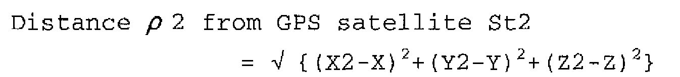

- When the time error of the clock of the
GPS receiver 11 is Δ t, a correct distance from each GPS satellite can be obtained by adding "light speed c x Δ t" to the result of each equation. In this case, the number of variables becomes four including Δ t, and therefore four GPS satellites are necessary to obtain the position of a vehicle. - Also, the relative velocity of the vehicle with respect to each GPS satellite can be obtained by differentiating the distance ρ of the GPS satellite with time, and the speed of the vehicle can be obtained from the relative velocity. Alternatively, the speed of a vehicle may be obtained based on the Doppler shift of the carrier wave L1. The Doppler shift is proportional to the difference between the speed of a vehicle and the speed of a GPS satellite. Therefore, the speed of a vehicle can be obtained based on the known speed of a GPS satellite and the Doppler shift. The Doppler shift can be calculated based on the change in the frequency of the carrier wave L1.
- As described above, using three or more GPS satellites is preferable to accurately detect the position of a vehicle. However, an embodiment of the present invention provides a positioning system that can accurately estimate the position of a vehicle even when less than three GPS satellites are available.
- The coordinates obtained from the above simultaneous equations are based on a reference frame called the world geodetic system (WGS). The
positioning unit 15 converts the obtained coordinates into the earth-fixed orthogonal coordinate system. In the present application, the position of a vehicle represented by the converted coordinates is called a satellite-based position. - The
positioning unit 15 is connected to aspeed sensor 12 and a gyro sensor 13 of theINS unit 14. Thespeed sensor 12, for example, detects pulses, i.e., changes in magnetic flux caused when protrusions, which are disposed at regular intervals along the circumference of a rotor of each wheel, pass through a detector, and measures the speed of the vehicle based on the number of pulses per unit time. - The gyro sensor 13 is a yaw rate sensor, such as a fiber-optic gyroscope or a vibratory gyroscope, that detects the angular speed of the rotation of a vehicle and obtains the angle or the traveling direction of the vehicle by integrating the detected angular speed. The gyro sensor 13 is preferably capable of detecting a three-axis direction or a three-dimensional direction of a vehicle.
- The
INS unit 14 estimates the current position of a vehicle by autonomous navigation, i.e., by updating the satellite-based position of the vehicle based on the travel distance obtained by thespeed sensor 12 and the traveling direction obtained by the gyro sensor 13 (hereafter, the position of a vehicle estimated by autonomous navigation is called an inertial-navigation-based position). - In other words, the
positioning unit 15 can estimate the current position of a vehicle based on the speed and direction of the vehicle detected by theINS unit 14 by autonomous navigation even when no radio signal is available from GPS satellites. - The satellite-based position and the inertial-navigation-based position are input into the
estimation unit 16. Based on the input positions and previously detected positions, theestimation unit 16 estimates errors in the input positions and thereby calculates a correction value for the inertial-navigation-based position. The correction value for the inertial-navigation-based position is input into theINS unit 14. TheINS unit 14 corrects the inertial-navigation-based position with the correction value and outputs the corrected inertial-navigation-based position to thepositioning unit 15. - The
estimation unit 16 calculates the correction value for the inertial-navigation-based position using, for example, the Kalman filter. The Kalman filter is an algorithm that estimates a most provable value from a measured value(s) including noise. The Kalman filter calculates a correction value so as to minimize the mean square error of an estimate obtained by processing inertial-navigation-based positions input in succession. Thus, theINS unit 14 accurately corrects the inertial-navigation-based position and outputs the corrected inertial-navigation-based position to thepositioning unit 15. - Alternatively, the
estimation unit 16 may be configured to estimate an error in the inertial-navigation-based position based on the input satellite-based position. In this case, theestimation unit 16 may be configured to correct the satellite-based position based on atmospheric conditions and/or the elevation angle when four or more GPS satellites are available, and to estimate an error in the inertial-navigation-based position estimated by theINS unit 14 based on the corrected satellite-based position. - Meanwhile, in this embodiment, the
estimation unit 16 is configured not to estimate an error in the satellite-based position, or configured to estimate an error in the satellite-based position but not to input a correction value for the satellite-based position to thepositioning unit 15. The Kalman filter is designed to estimate an error based on the tendency of previous measurements, and is therefore not suitable to estimate an error in the satellite-based position that is an instantaneously detected value. For example, if radio signals from GPS satellites are displaced greatly because of, for example, multipath transmission, the Kalman filter has to calculate correction values based on a satellite-based position having a large error for a substantial period of time after the displacement occurs. Therefore, in terms of accuracy of the satellite-based position, it is preferable not to correct the satellite-based position using a correction value obtained by the Kalman filter. - When three or more GPS satellites are available, even with a time error of the clock of the GPS receiver 11 (when the number of available GPS satellites is three), the position of a vehicle can be accurately estimated by obtaining a satellite-based position of the vehicle in a three-dimensional space based on radio signals from the GPS satellites and by correcting the obtained satellite-based position by autonomous navigation provided by the
INS unit 14. - However, when less than three GPS satellites are available, only a broad area including a vehicle position can be determined based on the distances from the GPS satellites.
FIG. 3A is a drawing illustrating an area that can be identified when one GPS satellite is available, andFIG. 3B is a drawing illustrating an area that can be identified when two GPS satellites are available. When only one GPS satellite is available, it is only possible to determine that a vehicle is at a certain position on a sphere, with every point on the sphere being at an equal distance from the GPS satellite. When only two GPS satellites are available, it is only possible to determine that a vehicle is at a certain position on a curved line where two spheres around the respective GPS satellites intersect, every point on the curved line being at an equal distance from the two GPS satellites. - When less than three GPS satellites are available, the
positioning system 10 of this embodiment determines a point in an area (defined as a sphere or a curved line) calculated based on the radio signals which point is closest to an inertial-navigation-based position obtained by autonomous navigation, and uses the determined point as a satellite-based position. - An exemplary process of estimating the position of a vehicle by the
positioning system 10 is described below with reference to a flowchart ofFIG. 4 . First, theGPS receiver 11 tries to receive radio signals from GPS satellites (S1). If no GPS satellite is available, autonomous navigation by theINS unit 14 is continued. - If radio signals from GPS satellites are received, the
positioning unit 15 compares the number of available GPS satellites and the number of variables necessary to calculate the position of a vehicle by the simultaneous equations described above (S2). As described above, four variables are necessary to correct even the time error of a clock, and three variables are necessary when the time error of a clock is corrected by a different method. In this embodiment, it is assumed that the number of variables is three. If the number of available GPS satellites is less than three, the process goes to step S3; and if the number of available GPS satellites is three or more, the process goes to step 4. - If the number of available GPS satellites is three or more, the
positioning unit 15 calculates a satellite-based position based on distances from the three or more GPS satellites (S4). - If the number of available GPS satellites is less than three, the
positioning unit 15 determines a position on a sphere or a curved line as shown inFIGS. 3A and 3B which position is closest to an inertial-navigation-based position obtained by theINS unit 14, and uses the determined position as a satellite-based position (S3). - Then, the
positioning unit 15 corrects the satellite-based position with the inertial-navigation-based position as in a normal position estimating process, and thereby estimates the position of the vehicle (S5). Thepositioning unit 15 may be configured to more accurately determine the position of a vehicle by mapping the estimated position of the vehicle onto a road map in themap database 20. The estimated position of the vehicle is sent to thecar navigation ECU 19. - Also, the
estimation unit 16 estimates a true value of the inertial-navigation-based position and feeds back a correction value for the inertial-navigation-based position to the INS unit 14 (S6). - Thus, according to an embodiment of the present invention, when less than three GPS satellites are available, a positioning system selects a satellite-based position closest to an inertial-navigation-based position from possible satellite-based positions defined as a sphere or a curved line, corrects the selected satellite-based position by autonomous navigation, and thereby estimates the position of a vehicle. This configuration makes it possible to accurately estimate the position of a vehicle even when only one or two GPS satellites are available. According to another embodiment of the present invention, the inertial-navigation-based position is corrected by the
estimation unit 16. This configuration further improves the accuracy of the selected satellite-based position that is closest to the inertial-navigation-based position. - Although the above embodiments of the present invention are described using a vehicle, the present invention may also be applied to a positioning system for estimating the position of other mobile bodies such as a ship and an aircraft. Further, although GPS satellites are used as radio stations in the above embodiments, radio stations on the ground may also be used.
- The present invention is not limited to the specifically disclosed embodiments, and variations and modifications may be made without departing from the scope of the present invention.
- The present international application claims priority from Japanese Patent Application No.
2006-042826 filed on June 20, 2006
Claims (5)
- A positioning system, comprising:a positioning unit configured to perform position estimation based on radio signals from artificial satellites; andan autonomous navigation unit configured to perform position estimation by autonomous navigation; whereinthe positioning unit and the autonomous navigation unit are configured to estimate a position of a mobile body in cooperation with each other; andwhen the number of the artificial satellites available is less than three, the positioning unit is configured to determine a point in an area calculated based on the radio signals which point is closest to an inertial-navigation-based position calculated by the autonomous navigation and to use the determined point as a satellite-based position estimated based on the radio signals.
- The positioning system as claimed in claim 1, wherein
when the number of the artificial satellites available is one, the area is defined as a sphere, with every point on the sphere being at an equal distance from the one of the artificial satellites; and
when the number of the artificial satellites available is two, the area is defined as a curved line where two spheres intersect, with every point on each of the two spheres being at an equal distance from the corresponding one of the two of the artificial satellites. - The positioning system as claimed in claim 1, further comprising:an estimation unit configured to calculate a correction value for the inertial-navigation-based position from previous values of the inertial-navigation-based position; whereinthe autonomous navigation unit is configured to correct the inertial-navigation-based position based on the correction value calculated by the estimation unit; andthe positioning unit is configured to determine the point in the area which point is closest to the corrected inertial-navigation-based position and to use the determined point as the satellite-based position.
- A positioning method using a positioning unit for performing position estimation based on radio signals from artificial satellites and an autonomous navigation unit for performing position estimation by autonomous navigation, where the positioning unit and the autonomous navigation unit estimate a position of a mobile body in cooperation with each other, the positioning method comprising the steps of:determining, by the positioning unit, whether the number of the artificial satellites available is less than three; anddetermining, by the positioning unit, a point in an area calculated based on the radio signals which point is closest to an inertial-navigation-based position calculated by the autonomous navigation and using the determined point as a satellite-based position estimated based on the radio signals when the number of the artificial satellites available is less than three.
- A car navigation system capable of displaying a road map together with a position of a vehicle which position is estimated by the positioning system of any one of claims 1 through 3.
Applications Claiming Priority (2)
| Application Number | Priority Date | Filing Date | Title |
|---|---|---|---|
| JP2006042826A JP4020143B2 (en) | 2006-02-20 | 2006-02-20 | Positioning system, positioning method and car navigation system |
| PCT/JP2007/052746 WO2007097245A1 (en) | 2006-02-20 | 2007-02-15 | Positioning system, positioning method and car navigation system |
Publications (3)
| Publication Number | Publication Date |
|---|---|
| EP1988408A1 true EP1988408A1 (en) | 2008-11-05 |
| EP1988408A4 EP1988408A4 (en) | 2012-11-21 |
| EP1988408B1 EP1988408B1 (en) | 2017-06-21 |
Family
ID=38437283
Family Applications (1)
| Application Number | Title | Priority Date | Filing Date |
|---|---|---|---|
| EP07714276.8A Expired - Fee Related EP1988408B1 (en) | 2006-02-20 | 2007-02-15 | Positioning system, positioning method and car navigation system |
Country Status (5)
| Country | Link |
|---|---|
| US (1) | US7869950B2 (en) |
| EP (1) | EP1988408B1 (en) |
| JP (1) | JP4020143B2 (en) |
| CN (1) | CN101384919B (en) |
| WO (1) | WO2007097245A1 (en) |
Cited By (1)
| Publication number | Priority date | Publication date | Assignee | Title |
|---|---|---|---|---|
| WO2018087257A1 (en) * | 2016-11-14 | 2018-05-17 | Volkswagen Aktiengesellschaft | Estimation of an individual position |
Families Citing this family (19)
| Publication number | Priority date | Publication date | Assignee | Title |
|---|---|---|---|---|
| CN101809409B (en) * | 2007-09-10 | 2012-06-13 | 三菱电机株式会社 | Navigation device |
| AU2008303078B2 (en) | 2007-09-28 | 2012-06-21 | Leica Geosystems Ag | A positioning system and method |
| US8190312B2 (en) * | 2008-03-13 | 2012-05-29 | General Electric Company | System and method for determining a quality of a location estimation of a powered system |
| US8965604B2 (en) | 2008-03-13 | 2015-02-24 | General Electric Company | System and method for determining a quality value of a location estimation of a powered system |
| JP5566039B2 (en) * | 2009-03-13 | 2014-08-06 | 富士通株式会社 | Positioning device |
| JP4968320B2 (en) | 2009-12-25 | 2012-07-04 | カシオ計算機株式会社 | Information acquisition device, position information storage method and program |
| US20110313650A1 (en) * | 2010-06-21 | 2011-12-22 | Qualcomm Incorporated | Inertial sensor orientation detection and measurement correction for navigation device |
| CN102023305A (en) * | 2010-08-05 | 2011-04-20 | 深圳市赛格导航科技股份有限公司 | Positioning method and device as well as vehicle-mounted terminal |
| JP2012122819A (en) * | 2010-12-08 | 2012-06-28 | Casio Comput Co Ltd | Positioning device, positioning method and program |
| KR20130035483A (en) * | 2011-09-30 | 2013-04-09 | 삼성전자주식회사 | Apparatus and method for perceiving heading change in mobile terminal |
| CN102621570B (en) * | 2012-04-11 | 2013-10-23 | 清华大学 | Automobile dynamic parameter measuring method based on double global positioning and inertia measurement |
| US10012736B2 (en) * | 2013-03-12 | 2018-07-03 | Lockheed Martin Corporation | System and process of determining vehicle attitude |
| US20150149085A1 (en) * | 2013-11-27 | 2015-05-28 | Invensense, Inc. | Method and system for automatically generating location signatures for positioning using inertial sensors |
| CN104008652B (en) * | 2014-06-16 | 2016-08-24 | 上海萃智工业技术有限公司 | A kind of vehicle monitoring system based on integrated navigation |
| CN104697536A (en) * | 2015-02-12 | 2015-06-10 | 奇瑞汽车股份有限公司 | Vehicle positioning method and apparatus |
| US9964949B2 (en) * | 2015-12-18 | 2018-05-08 | Gm Global Technology Operation Llc | Operating modes for autonomous driving |
| DE102017100060A1 (en) * | 2017-01-03 | 2018-07-05 | Valeo Schalter Und Sensoren Gmbh | Determination of motion information with environmental sensors |
| US11447134B2 (en) * | 2019-09-18 | 2022-09-20 | Aptiv Technologies Limited | Vehicle route modification to improve vehicle location information |
| CN110631588B (en) * | 2019-09-23 | 2022-11-18 | 电子科技大学 | Unmanned aerial vehicle visual navigation positioning method based on RBF network |
Citations (4)
| Publication number | Priority date | Publication date | Assignee | Title |
|---|---|---|---|---|
| US4731613A (en) * | 1984-12-07 | 1988-03-15 | Nissan Motor Company, Limited | Positioning system for a vehicle |
| US6249246B1 (en) * | 1996-11-04 | 2001-06-19 | Robert Bosch Gmbh | Location sensor having a satellite receiver for position determination |
| US20030055561A1 (en) * | 2001-09-18 | 2003-03-20 | Fujitsu Limited | Position measurement device, terminal provided therewith, and position measurement method |
| WO2004070318A1 (en) * | 2003-02-06 | 2004-08-19 | Nordnav Technologies Ab | A navigation method and apparatus |
Family Cites Families (16)
| Publication number | Priority date | Publication date | Assignee | Title |
|---|---|---|---|---|
| JPS63247613A (en) * | 1987-04-02 | 1988-10-14 | Mazda Motor Corp | Navigation device for vehicle |
| JPH0247577A (en) * | 1988-08-09 | 1990-02-16 | Nissan Motor Co Ltd | Position measuring apparatus for vehicle |
| JPH02159590A (en) * | 1988-12-12 | 1990-06-19 | Japan Radio Co Ltd | Measuring apparatus of own position |
| JP2916708B2 (en) * | 1990-10-26 | 1999-07-05 | 本田技研工業株式会社 | Current position measurement device for moving objects |
| JP3303175B2 (en) * | 1993-03-17 | 2002-07-15 | アイシン精機株式会社 | On-board positioning device |
| JPH0760175A (en) | 1993-08-30 | 1995-03-07 | Mitsubishi Heavy Ind Ltd | Method and device for controlling fountain production |
| JPH0875479A (en) | 1994-09-06 | 1996-03-22 | Matsushita Electric Ind Co Ltd | Radio navigation device |
| JPH1019580A (en) * | 1996-06-28 | 1998-01-23 | Mitsubishi Electric Corp | Gps receiver |
| JP3833786B2 (en) * | 1997-08-04 | 2006-10-18 | 富士重工業株式会社 | 3D self-position recognition device for moving objects |
| US6278945B1 (en) * | 1997-11-24 | 2001-08-21 | American Gnc Corporation | Fully-coupled positioning process and system thereof |
| EP1130358B1 (en) * | 2000-03-01 | 2006-06-28 | Matsushita Electric Industrial Co., Ltd. | Navigation device |
| CN1285518A (en) * | 2000-09-05 | 2001-02-28 | 泉州海洋高科技电子有限公司 | Positioning communication assembling system |
| CN1361430A (en) * | 2000-12-23 | 2002-07-31 | 林清芳 | Enhanced motion body pisition and navigation method and system |
| US20040234983A1 (en) | 2001-06-12 | 2004-11-25 | Pierre Cosson | Method for assessing the virulence of pathogens and uses thereof |
| CN1235017C (en) * | 2002-10-08 | 2006-01-04 | 曲声波 | Vehicle position detection apparatus and treatment method |
| WO2021124379A1 (en) * | 2019-12-16 | 2021-06-24 | Tdk株式会社 | Reservoir element |
-
2006
- 2006-02-20 JP JP2006042826A patent/JP4020143B2/en active Active
-
2007
- 2007-02-15 CN CN2007800015128A patent/CN101384919B/en not_active Expired - Fee Related
- 2007-02-15 EP EP07714276.8A patent/EP1988408B1/en not_active Expired - Fee Related
- 2007-02-15 US US12/089,645 patent/US7869950B2/en active Active
- 2007-02-15 WO PCT/JP2007/052746 patent/WO2007097245A1/en active Application Filing
Patent Citations (4)
| Publication number | Priority date | Publication date | Assignee | Title |
|---|---|---|---|---|
| US4731613A (en) * | 1984-12-07 | 1988-03-15 | Nissan Motor Company, Limited | Positioning system for a vehicle |
| US6249246B1 (en) * | 1996-11-04 | 2001-06-19 | Robert Bosch Gmbh | Location sensor having a satellite receiver for position determination |
| US20030055561A1 (en) * | 2001-09-18 | 2003-03-20 | Fujitsu Limited | Position measurement device, terminal provided therewith, and position measurement method |
| WO2004070318A1 (en) * | 2003-02-06 | 2004-08-19 | Nordnav Technologies Ab | A navigation method and apparatus |
Non-Patent Citations (1)
| Title |
|---|
| See also references of WO2007097245A1 * |
Cited By (1)
| Publication number | Priority date | Publication date | Assignee | Title |
|---|---|---|---|---|
| WO2018087257A1 (en) * | 2016-11-14 | 2018-05-17 | Volkswagen Aktiengesellschaft | Estimation of an individual position |
Also Published As
| Publication number | Publication date |
|---|---|
| US20100169006A1 (en) | 2010-07-01 |
| WO2007097245A1 (en) | 2007-08-30 |
| CN101384919B (en) | 2012-01-04 |
| JP2007218865A (en) | 2007-08-30 |
| US7869950B2 (en) | 2011-01-11 |
| JP4020143B2 (en) | 2007-12-12 |
| CN101384919A (en) | 2009-03-11 |
| EP1988408B1 (en) | 2017-06-21 |
| EP1988408A4 (en) | 2012-11-21 |
Similar Documents
| Publication | Publication Date | Title |
|---|---|---|
| EP1988408B1 (en) | Positioning system, positioning method and car navigation system | |
| US7756639B2 (en) | System and method for augmenting a satellite-based navigation solution | |
| JP4550255B2 (en) | Method and apparatus for improving dead reckoning distance calculations for vehicle navigation systems | |
| US10267920B2 (en) | Positioning method | |
| WO2014002211A1 (en) | Positioning device | |
| EP1457946A1 (en) | Apparatus for detecting location of mobile body in navigation system and method thereof | |
| EP2146217A1 (en) | Integrity of differential gps corrections in navigation devices using military type gps receivers | |
| EP2219044A1 (en) | Navigation method, navigation system, navigation device, vehicle provided therewith and group of vehicles | |
| JP2011209268A (en) | Position estimating device and program | |
| JP2015230218A (en) | Moving distance estimation apparatus | |
| US7184887B2 (en) | Method and apparatus for calculating a figure of merit for GPS position using NMEA 0183 output | |
| KR100526571B1 (en) | Off-board navigation system and method for calibrating error using the same | |
| US20100299059A1 (en) | Method for operating a navigation system and a navigation system | |
| JPH10111137A (en) | Gps navigator | |
| JP4646720B2 (en) | Navigation device | |
| JP2783924B2 (en) | Vehicle position detection device | |
| JP2009036651A (en) | Navigation apparatus, navigation method and navigation program | |
| US5928295A (en) | Method and apparatus for automatic calibration of the wheel track of a movable vehicle | |
| KR100572317B1 (en) | Navigation system using global positioning system located at crossroads | |
| JP2008249614A (en) | Onboard navigation device, navigation system, and computer program | |
| JP2007155644A (en) | Gps receiver, and car navigation system | |
| Kealy et al. | Improving the performance of satellite navigation systems for land mobile applications through the integration of MEMS inertial sensors | |
| JP2013083464A (en) | Navigation device | |
| KR100491168B1 (en) | Measuring system for position and posture using multi-GPS constrained geometricaly | |
| KR20090049501A (en) | Method and apparatus for complementing position in vehicle |
Legal Events
| Date | Code | Title | Description |
|---|---|---|---|
| PUAI | Public reference made under article 153(3) epc to a published international application that has entered the european phase |
Free format text: ORIGINAL CODE: 0009012 |
|
| 17P | Request for examination filed |
Effective date: 20080410 |
|
| AK | Designated contracting states |
Kind code of ref document: A1 Designated state(s): DE FR |
|
| RBV | Designated contracting states (corrected) |
Designated state(s): DE FR |
|
| DAX | Request for extension of the european patent (deleted) | ||
| A4 | Supplementary search report drawn up and despatched |
Effective date: 20121019 |
|
| RIC1 | Information provided on ipc code assigned before grant |
Ipc: G01S 5/14 20060101AFI20121015BHEP Ipc: G01C 21/28 20060101ALI20121015BHEP Ipc: G01S 19/49 20100101ALI20121015BHEP Ipc: G01C 21/00 20060101ALI20121015BHEP |
|
| RAP1 | Party data changed (applicant data changed or rights of an application transferred) |
Owner name: TOYOTA JIDOSHA KABUSHIKI KAISHA |
|
| 17Q | First examination report despatched |
Effective date: 20130924 |
|
| GRAP | Despatch of communication of intention to grant a patent |
Free format text: ORIGINAL CODE: EPIDOSNIGR1 |
|
| INTG | Intention to grant announced |
Effective date: 20170209 |
|
| GRAS | Grant fee paid |
Free format text: ORIGINAL CODE: EPIDOSNIGR3 |
|
| GRAA | (expected) grant |
Free format text: ORIGINAL CODE: 0009210 |
|
| AK | Designated contracting states |
Kind code of ref document: B1 Designated state(s): DE FR |
|
| REG | Reference to a national code |
Ref country code: DE Ref legal event code: R096 Ref document number: 602007051395 Country of ref document: DE |
|
| REG | Reference to a national code |
Ref country code: DE Ref legal event code: R084 Ref document number: 602007051395 Country of ref document: DE |
|
| REG | Reference to a national code |
Ref country code: FR Ref legal event code: PLFP Year of fee payment: 12 |
|
| REG | Reference to a national code |
Ref country code: DE Ref legal event code: R097 Ref document number: 602007051395 Country of ref document: DE |
|
| PLBE | No opposition filed within time limit |
Free format text: ORIGINAL CODE: 0009261 |
|
| STAA | Information on the status of an ep patent application or granted ep patent |
Free format text: STATUS: NO OPPOSITION FILED WITHIN TIME LIMIT |
|
| 26N | No opposition filed |
Effective date: 20180322 |
|
| PGFP | Annual fee paid to national office [announced via postgrant information from national office to epo] |
Ref country code: DE Payment date: 20211230 Year of fee payment: 16 |
|
| PGFP | Annual fee paid to national office [announced via postgrant information from national office to epo] |
Ref country code: FR Payment date: 20220118 Year of fee payment: 16 |
|
| P01 | Opt-out of the competence of the unified patent court (upc) registered |
Effective date: 20230427 |
|
| REG | Reference to a national code |
Ref country code: DE Ref legal event code: R119 Ref document number: 602007051395 Country of ref document: DE |
|
| PG25 | Lapsed in a contracting state [announced via postgrant information from national office to epo] |
Ref country code: FR Free format text: LAPSE BECAUSE OF NON-PAYMENT OF DUE FEES Effective date: 20230228 Ref country code: DE Free format text: LAPSE BECAUSE OF NON-PAYMENT OF DUE FEES Effective date: 20230901 |