EP1990709A2 - Device for identifying a hand-written user entry electronically - Google Patents
Device for identifying a hand-written user entry electronically Download PDFInfo
- Publication number
- EP1990709A2 EP1990709A2 EP08003984A EP08003984A EP1990709A2 EP 1990709 A2 EP1990709 A2 EP 1990709A2 EP 08003984 A EP08003984 A EP 08003984A EP 08003984 A EP08003984 A EP 08003984A EP 1990709 A2 EP1990709 A2 EP 1990709A2
- Authority
- EP
- European Patent Office
- Prior art keywords
- housing
- edge
- input field
- input
- user input
- Prior art date
- Legal status (The legal status is an assumption and is not a legal conclusion. Google has not performed a legal analysis and makes no representation as to the accuracy of the status listed.)
- Granted
Links
Images


Classifications
-
- G—PHYSICS
- G06—COMPUTING; CALCULATING OR COUNTING
- G06F—ELECTRIC DIGITAL DATA PROCESSING
- G06F3/00—Input arrangements for transferring data to be processed into a form capable of being handled by the computer; Output arrangements for transferring data from processing unit to output unit, e.g. interface arrangements
- G06F3/01—Input arrangements or combined input and output arrangements for interaction between user and computer
- G06F3/048—Interaction techniques based on graphical user interfaces [GUI]
- G06F3/0487—Interaction techniques based on graphical user interfaces [GUI] using specific features provided by the input device, e.g. functions controlled by the rotation of a mouse with dual sensing arrangements, or of the nature of the input device, e.g. tap gestures based on pressure sensed by a digitiser
- G06F3/0488—Interaction techniques based on graphical user interfaces [GUI] using specific features provided by the input device, e.g. functions controlled by the rotation of a mouse with dual sensing arrangements, or of the nature of the input device, e.g. tap gestures based on pressure sensed by a digitiser using a touch-screen or digitiser, e.g. input of commands through traced gestures
- G06F3/04883—Interaction techniques based on graphical user interfaces [GUI] using specific features provided by the input device, e.g. functions controlled by the rotation of a mouse with dual sensing arrangements, or of the nature of the input device, e.g. tap gestures based on pressure sensed by a digitiser using a touch-screen or digitiser, e.g. input of commands through traced gestures for inputting data by handwriting, e.g. gesture or text
-
- G—PHYSICS
- G06—COMPUTING; CALCULATING OR COUNTING
- G06F—ELECTRIC DIGITAL DATA PROCESSING
- G06F3/00—Input arrangements for transferring data to be processed into a form capable of being handled by the computer; Output arrangements for transferring data from processing unit to output unit, e.g. interface arrangements
- G06F3/01—Input arrangements or combined input and output arrangements for interaction between user and computer
- G06F3/03—Arrangements for converting the position or the displacement of a member into a coded form
- G06F3/033—Pointing devices displaced or positioned by the user, e.g. mice, trackballs, pens or joysticks; Accessories therefor
- G06F3/0354—Pointing devices displaced or positioned by the user, e.g. mice, trackballs, pens or joysticks; Accessories therefor with detection of 2D relative movements between the device, or an operating part thereof, and a plane or surface, e.g. 2D mice, trackballs, pens or pucks
- G06F3/03547—Touch pads, in which fingers can move on a surface
-
- G—PHYSICS
- G06—COMPUTING; CALCULATING OR COUNTING
- G06F—ELECTRIC DIGITAL DATA PROCESSING
- G06F3/00—Input arrangements for transferring data to be processed into a form capable of being handled by the computer; Output arrangements for transferring data from processing unit to output unit, e.g. interface arrangements
- G06F3/01—Input arrangements or combined input and output arrangements for interaction between user and computer
- G06F3/03—Arrangements for converting the position or the displacement of a member into a coded form
- G06F3/041—Digitisers, e.g. for touch screens or touch pads, characterised by the transducing means
-
- G—PHYSICS
- G06—COMPUTING; CALCULATING OR COUNTING
- G06V—IMAGE OR VIDEO RECOGNITION OR UNDERSTANDING
- G06V40/00—Recognition of biometric, human-related or animal-related patterns in image or video data
- G06V40/30—Writer recognition; Reading and verifying signatures
Definitions
- a real-time clock can be integrated in the present device 1 for the electronic detection of a user input, so that each recorded record of the lettering coordinates and / or the actuating pressure can be assigned a time stamp generated by the real-time clock.
- an identification code is added to each recorded data set of the lettering coordinates and / or of the actuating pressure, which is individualized for the device used for the detection.
- This identification code can be stored in a memory chip arranged in the housing 2, preferably designed as a ROM.
- a further improvement in data security is achieved if a processor arranged in the housing 2 generates a process-identification code individualizing the input with each user input and adds it to the data record of the lettering coordinates and / or the actuating pressure.
- the operational readiness of the device according to the invention is shown by an LED lamp 32, which is indicated in the left lower portion of the housing 2 as a horizontal elongate member.
- This LED light 32 may, for example, light green if a signature is to be detected, orange / yellow, if the operational readiness is given, it may glow red if there is a fault.
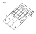
- Fig. 7 shows the inside of the housing back 4 shown. This is designed here as a plastic injection molded part.
- Fig. 8 shows the inside of the front part 3 of the housing. 1
Abstract
Description
Die vorliegende Erfindung betrifft eine Vorrichtung zur elektronischen Erfassung einer handschriftlichen Benutzereingabe wie beispielsweise eine Signatur bzw. Unterschrift. Derartige Vorrichtungen sind auch unter dem Begriff "Signaturpads" bekannt.The present invention relates to a device for the electronic detection of a handwritten user input, such as a signature or signature. Such devices are also known by the term "signature pads".
Vorrichtungen der eingangs genannten Art werden beispielsweise von der Fa. StepOver GmbH / Deutschland u.a. unter den Markennamen: blueMobile Pad, plusPad, blueM Pad und +Pad II/III, vertrieben. Auch die
Bei den eingangs genannten Vorrichtungen bzw. Signaturpads ist das Eingabefeld, auf dem ein Benutzer mit Hilfe einer Schreibeinrichtung eine handschriftliche Benutzereingabe leisten kann, die dann elektronisch erfasst wird, gegenüber den rechten und linken Gehäuserändern dieser Vorrichtung zentriert bzw. mittig angeordnet. Man hat nun festgestellt, dass ein Benutzer auf dem Eingabefeld derartiger bekannter Vorrichtungen nicht optimal unterschreiben kann, da die Geräte bzw. die Gehäuse relativ kleine Außenabmessungen haben, aber aufgrund deren technischen Aufbaus auch eine Mindestdicke von mehr als 1,6 cm oder sogar mehr als 2,0 cm aufweisen. Dadurch kann ein Benutzer einerseits beim Unterschreiben auf dem Eingabefeld seine Schreibhand nicht vollständig auf dem Gehäuse auflegen, andererseits ist es dem Benutzer aufgrund der Mindestdicke nicht zumutbar, weil unbequem beim Schreiben, die Schreibhand zum Teil auf dem Gehäuse und zum Teil auf der Unterlage oder der Wand abzustützen.In the case of the devices or signature pads mentioned at the outset, the input field on which a user can make a handwritten user input with the aid of a writing device, which is then detected electronically, is centered or centered relative to the right and left housing edges of this device. It has now been found that a user can not optimally sign on the input field of such known devices, since the devices or the housing have relatively small outer dimensions, but due whose technical construction also has a minimum thickness of more than 1.6 cm or even more than 2.0 cm. As a result, a user on the one hand when signing on the input field not completely put his writing hand on the case, on the other hand, it is the user due to the minimum thickness unreasonable because inconvenient in writing, the writing hand partly on the housing and partly on the pad or the Support wall.
Insgesamt ist festzustellen, dass die bekannten Vorrichtungen der eingangs genannten Art zur elektronischen Erfassung einer handschriftlichen Benutzereingabe im Hinblick auf die von einem Benutzer zu leistende Eingabe auf dem Eingabefeld derartiger Vorrichtungen zu verbessern sind.Overall, it should be noted that the known devices of the type mentioned above for the electronic detection of a handwritten user input with regard to the input to be made by a user on the input field of such devices are to be improved.
Das der Erfindung zugrundeliegende technische Problem besteht darin, eine Vorrichtung zur elektronischen Erfassung einer handschriftlichen Benutzereingabe benutzerfreundlicher zu gestalten.The technical problem underlying the invention is to make a device for the electronic detection of a handwritten user input user-friendly.
Dieses technische Problem wird gemäß einem ersten Aspekt der vorliegenden Erfindung durch eine Vorrichtung zur elektronischen Erfassung einer handschriftlichen Benutzereingabe gelöst, die ein Gehäuse und ein in dem Gehäuse angeordnetes Eingabefeld aufweist. Das Gehäuse besitzt eine Vorderseite, eine der Vorderseite gegenüberliegende Rückseite, einen rechten Gehäuserand, einen dem rechten Gehäuserand gegenüberliegenden linken Gehäuserand, einen unteren Gehäuserand und einen dem unteren Gehäuserand gegenüberliegenden oberen Gehäuserand. Das Eingabefeld ist dazu ausgebildet, eine handschriftliche Benutzereingabe, die ein Benutzer mit Hilfe einer Schreibeinrichtung auf dem Benutzereingabefeld leistet, elektronisch zu erfassen. In dem Gehäuse ist selbstverständlich die für die elektronische Erfassung und eventuelle Abspeicherung der entsprechenden digitalen Daten, die der durch den Benutzer getätigten Eingabe entsprechen, untergebracht. Das Eingabefeld ist auf der Vorderseite des Gehäuses asymmetrisch zwischen dem rechten Gehäuserand und dem linken Gehäuserand angeordnet. Das Eingabefeld kann zudem dazu ausgebildet sein, die handschriftliche Benutzereingabe und/oder Eingabeelemente etc. darzustellen.This technical problem is solved according to a first aspect of the present invention by a device for electronically detecting a handwritten user input, which has a housing and an input field arranged in the housing. The housing has a front side, a rear side opposite the front side, a right housing edge, a left housing edge opposite the right housing edge, a lower housing edge and an upper housing edge opposite the lower housing edge. The input field is designed to electronically record a handwritten user input, which a user makes using a writing device on the user input field. The housing accommodates, of course, the electronic detection and eventual storage of the corresponding digital data corresponding to the input made by the user. The input field is arranged asymmetrically on the front of the housing between the right edge of the housing and the left housing edge. The input field can also be designed to represent the handwritten user input and / or input elements, etc.
Der Erfindung gemäß dem ersten Aspekt liegt der Gedanke zugrunde, das Eingebefeld derart außermittig anzuordnen, dass für einen Benutzer, trotz der im Vergleich mit bisherigen Vorrichtungen grundsätzlich gleichen Abmessungen der Gehäuse, die Fläche, die einem Benutzer während der Eingabe zur Auflage der Schreibhand zur Verfügung steht, vergrößert ist. Die asymmetrische Anordnung ermöglicht zudem eine natürlichere Schreibhaltung des Benutzers während der Eingabe.The invention according to the first aspect is based on the idea to arrange the input field off-center so that, for a user, despite the basically same dimensions of the housing in comparison with previous devices, the area available to a user during the input to rest the writing hand stands, is enlarged. The asymmetric arrangement also allows a more natural writing posture of the user during input.
Erfindungsgemäß kann also für einen Rechtshänder bei der Eingabe mittels der Schreibeinrichtung auf dem Eingabefeld eine größere Fläche zwischen dem rechten Rand des Eingabefelds und dem rechten Gehäuserand geschaffen werden, wenn das Eingabefeld gegenüber der mittigen Platzierung mehr zum linken Gehäuserand versetzt angeordnet ist. Gleichzeitig kann in diesem Fall der rechtshändige Benutzer, der die Schreibeinrichtung bei der Eingabe in der rechten Hand hält, die rechte Hand bei der Eingabe wie beim Schreiben auf einem großen Blatt Papier in natürlicherer Haltung auf dem Gehäuse auflegen.Thus, according to the invention, a larger area between the right edge of the input field and the right edge of the housing can be created for a right-handed user when entering by means of the writing device when the input field is more offset relative to the central placement to the left edge of the housing. At the same time, in this case, the right-handed user who holds the writing device in the right hand input can rest his right hand on the case as typed on a large sheet of paper on the case as typed.
Im Fall einer Ausführung für einen Linkshänder kann erfindungsgemäß das Eingabefeld gegenüber der mittigen Anordnung mehr nach rechts versetzt angeordnet sein, so dass eine größere Auflagefläche für die Schreibhand zwischen dem linken Rand des Eingabefelds und dem linken Gehäuserand geschaffen ist. Auch in diesem Fall kann der linkshändige Benutzer, der die Schreibeinrichtung bei der Eingabe in der linken Hand hält, die linke Hand bei der Eingabe wie beim Schreiben auf einem Blatt Papier in natürlicherer Haltung auf dem Gehäuse auflegen.In the case of a version for a left-handed person, according to the invention, the input field can be arranged more offset to the right with respect to the central arrangement, so that a larger support surface is created for the writing hand between the left edge of the input field and the left housing edge. Also in this case, the left-handed user holding the writing device in the input in the left hand can put the left hand in the input as in writing on a sheet of paper in a more natural attitude on the housing.
Gemäß einer beispielhaften Ausführungsform der vorliegenden Erfindung ist es möglich, die Vorrichtung sowohl für Rechts- und Linkshänder einzusetzen. Dazu ist das Gehäuse von der Position für einen Rechtshänder um 180° um eine imaginäre Symmetrieachse (Achse, die vertikal zur Vorderseite des Gehäuses steht) der Vorrichtung zu drehen. Damit hat auch ein Linkshänder mehr Auflagefläche für seine linke Hand auf der Vorderseite des Gehäuses bei der Eingabe auf dem Eingabefeld, wenn er den Stift in der linken Hand hält.According to an exemplary embodiment of the present invention, it is possible to use the device for both right and left handed users. For this purpose, the housing is to be rotated 180 ° from the right-handed position about an imaginary axis of symmetry (axis vertical to the front of the housing) of the device. Thus, a left-hander has more support surface for his left hand on the front of the case when typing on the input field when he holds the pen in his left hand.
Die für einen Benutzer beim Unterschreiben auf dem Eingabefeld zur Verfügung stehende Fläche auf der Vorderseite des Gehäuses kann noch weiter vergrößert werden, wenn das Eingabefeld asymmetrisch zwischen dem unteren Gehäuserand und dem oberen Gehäuserand angeordnet ist. Mit anderen Worten: Das Eingabefeld ist in der Schreibposition für einen Rechtshänder näher zum oberen Gehäuserand hin verlagert, so dass der Abstand zwischen dem oberen Rand des Eingabefelds und dem oberen Gehäuserand kleiner ist als der Abstand zwischen dem unteren Gehäuserand und dem unteren Rand des Eingabefelds. Damit wird gewährleistet, dass die Handauflagefläche auf der Vorderseite des Gehäuses für einen Rechtshänder, das heißt also die Fläche zwischen dem unteren Gehäuserand und dem unteren Rand des Eingabefelds, größer ist als bisher; auch wenn man beispielsweise die Gesamtabmessungen des Gehäuses gegenüber den bekannten Gehäusen derartiger Vorrichtungen bzw. Signaturpads unverändert lässt.The area available to a user when signing on the input field on the front of the housing can be further increased if the input field is arranged asymmetrically between the lower edge of the housing and the upper edge of the housing. In other words, in the writing position for a right-handed person, the input field is shifted closer to the upper edge of the housing so that the distance between the upper edge of the input field and the upper edge of the housing is smaller than the distance between the lower edge of the housing and the lower edge of the input field. This ensures that the palm rest area on the front of the housing for a right-handed person, that is, the area between the lower edge of the housing and the lower edge of the input field, is greater than previously; even if, for example, leaves the overall dimensions of the housing over the known housings such devices or signature pads unchanged.
Wie oben bereits erwähnt, ist es aufgrund der erfindungsgemäßen asymmetrischen Anordnung des Eingabefelds gegenüber zumindest einem Paar von Gehäuserändern möglich, die Handauflagefläche für einen Benutzer trotz beispielsweise unveränderter Gesamtabmessungen des Gehäuses zu vergrößern und eine derartige Vorrichtung sowohl für Rechts- als auch Linkshänder einzusetzen. Gemäß einer beispielhaften Ausführungsform der vorliegenden Erfindung ist es möglich, das Benutzereingabefeld umschaltbar auszugestalten, so dass in einer ersten Benutzungsposition eine Benutzereingabe lagegerecht elektronisch erfassbar ist, nämlich beispielsweise in der Lageposition, die für einen Rechtshänder bestimmt ist, und in einer zweiten Benutzungsposition, die von der ersten Benutzungsposition verschieden ist, nämlich beispielsweise um 180° und für einen Linkshänder bestimmt ist, wiederum eine Benutzereingabe lagegerecht elektronisch erfassbar ist. Es wird z.B. eine auf dem Eingabefeld angezeigte Unterschriftslinie sowohl in der ersten als auch in der zweiten Benutzungsposition immer für den Benutzer symbolisch korrekt im unteren Bereich des Eingabefelds angezeigt, damit der Benutzer in der ersten und der zweiten Benutzungsposition auf dieser Linie seine Unterschrift tätigt.As already mentioned above, due to the inventive asymmetric arrangement of the input field compared to at least one pair of housing edges, it is possible to enlarge the palm rest area for a user despite, for example, unchanged overall dimensions of the housing and to use such a device for both right and left-handers. According to an exemplary embodiment of the present invention, it is possible to make the user input field switchable, so that in a first use position, a user input is electronically detectable, namely, for example, in the position of position that is intended for a right-handed person, and in a second position of use the first use position is different, namely, for example, by 180 ° and is intended for a left-hander, in turn, a user input is electronically detected positionally correct. It is e.g. a signature line displayed on the input field in both the first and in the second use position always displayed to the user symbolically correct in the lower part of the input field, so that the user in the first and the second use position on this line makes his signature.
Zudem kann es gemäß einer weiteren beispielhaften Ausführungsform der vorliegenden Erfindung vorteilhaft sein, die Umschaltbarkeit des Eingabefelds so auszugestalten, dass die zu leistende Eingabe (z.B. eine Unterschrift oder Signatur) lagegerecht korrekt erfasst wird. Mit anderen Worten: Das dem Eingabefeld zuzuordnenden Koordinatensystem wird in Abhängigkeit der Benutzungsposition geändert, so dass unabhängig davon, in welcher Benutzungsposition die Eingabe getätigt wurde, die erfassten zugehörigen Daten gleich sind.In addition, according to a further exemplary embodiment of the present invention, it may be advantageous to configure the switchability of the input field in such a way that the input to be made (for example a signature or signature) is recorded correctly in the correct position. In other words, the coordinate system to be assigned to the input field is changed as a function of the use position, so that regardless of the position in which the input was made, the acquired associated data is the same.
In einer weiteren beispielhaften Ausführungsform der vorliegenden Erfindung ist auf dem Benutzereingabefeld ein visuelles Symbol angezeigt, das aktivierbar ist. Die Aktivierbarkeit kann so ausgebildet sein, dass durch Tippen auf das Symbol mittels dem Schreibelement eine Umschaltung des Benutzereingabefelds von einer Benutzungsposition in eine andere Benutzungsposition erfolgt, beispielsweise von einer Rechtshänderbenutzerposition in eine Benutzungsposition für einen Linkshänder. Gleichzeitig wird elektronisch geschaltet, dass die Unterschrift dann beispielsweise um 180° verdreht durch einen Linkshänder erfolgt. Die Abspeicherung der erfassten Daten wird dann umgerechnet in ein allgemeines Koordinatensystem, das auch für die Unterschrift eines Rechtshänders gilt.In another exemplary embodiment of the present invention, a visual icon that is activatable is displayed on the user input field. The activatability may be such that by tapping the symbol by means of the write element, the user input field is switched from one use position to another use position, for example from a right-handed user position to a use position for a left-hander. At the same time electronically switched that the signature is then rotated, for example, by 180 ° by a left-handed. The storage of the recorded data is then converted into a general coordinate system, which also applies to the signature of a right-hander.
Gemäß einem weiteren Aspekt der vorliegenden Erfindung wird die Benutzerfreundlichkeit einer elektronischen Vorrichtung der eingangs genannten Art bzw. eines Signaturpads dadurch verbessert, dass die elektronischen Bauelemente, die zum Betrieb des Benutzereingabefelds und für die elektronische Erfassung der Benutzereingabe notwendig sind, im Gehäuseinnern zwischen dem unteren Gehäuserand und dem Benutzereingabefeld platziert sind. Entgegen den bisherigen Ausgestaltungen von Signaturpads mit Bildschirm (wie beispielsweise LCD-Display, TFT-Display etc.), bei denen diese elektronischen Bauelemente unterhalb des Benutzerfelds platziert waren, ist es nunmehr möglich, die Gesamtdicke des Gehäuses und somit der Vorrichtung an sich zu verringern. Beispielsweise ist es möglich, die Gesamt- oder Maximaldicke des Gehäuses bzw. der Vorrichtung auf ca. 1,3 cm oder sogar weniger als ca. 1,1 cm zu verringern. Für einen Benutzer kann es weitaus angenehmer sein, auf einem derart flachen Gehäuse beim Unterschreiben seine Hand auf dem Gehäuse bzw. essen Auflagefläche abzulegen als bisher, da dann die "Abstufung" zur Unterlage weniger spürbar und damit für den Benutzer weniger unangenehm ist. Hierzu ist ergänzend anzumerken, dass die Verlagerung der elektronischen Bauelemente, die die Verringerung der Gesamtdicke der Vorrichtung bzw. des Gehäuses der Vorrichtung ermöglichen kann, auch unabhängig von der asymmetrischen Anordnung des Benutzereingabefelds gegenüber dem Gehäuse vorgesehen werden kann.In accordance with another aspect of the present invention, the ease of use of an electronic device of the type mentioned above or of a signature pad is improved by virtue of the fact that the electronic components necessary for operating the user input field and for electronically detecting the user input are located inside the housing between the lower edge of the housing and the user input field. Contrary to the previous embodiments of signature pads with screen (such as LCD display, TFT display, etc.) in which these electronic components were placed below the user field, it is now possible to reduce the overall thickness of the housing and thus the device itself , For example, it is possible to reduce the total or maximum thickness of the housing or device to about 1.3 cm or even less than about 1.1 cm. For a user, it can be far more pleasant to place his hand on the housing or eat support surface on such a flat housing when signing than before, since then the "gradation" to the pad less noticeable and thus less unpleasant for the user. It should additionally be noted that the displacement of the electronic components, which may allow the reduction of the total thickness of the device or of the housing of the device, can also be provided independently of the asymmetrical arrangement of the user input field relative to the housing.
Gemäß einem weiteren Aspekt der vorliegenden Erfindung wird somit eine Vorrichtung zur elektronischen Erfassung einer Benutzereingabe wie beispielsweise eine Unterschrift vorgeschlagen, bei dem ein Gehäuse und ein Benutzereingabefeld vorhanden sind. Das Gehäuse besitzt einen Gehäuseinnenraum, eine Vorderseite, eine der Vorderseite gegenüberliegende Rückseite, einen rechten Gehäuserand, einen dem rechten Gehäuserand gegenüberliegenden linken Gehäuserand, einen unteren Gehäuserand und einen dem unteren Gehäuserand gegenüberliegenden oberen Gehäuserand. Das Benutzereingabefeld ist dazu ausgebildet, eine handschriftliche Benutzereingabe, die ein Benutzer mit Hilfe einer Schreibeinrichtung auf dem Benutzereingabefeld leistet, elektronisch zu erfassen. Die Elektronik bzw. die elektronischen Bauelemente, die zum Betrieb des Benutzereingabefelds und für die elektronische Erfassung der Benutzereingabe erforderlich sind, sind im Gehäuseinnenraum zwischen dem unteren Gehäuserand und dem Benutzereingabefeld platziert, so dass die Dicke des Gehäuses zwischen der Vorderseite und der gegenüberliegenden Rückseite des Gehäuses weniger als ca. 1,3 cm, insbesondere ca. 1,1 cm oder sogar ca. 1,0 cm beträgt.Thus, according to another aspect of the present invention, there is provided a device for electronically detecting a user input, such as a signature, in which a housing and a user input field are present. The housing has a housing interior, a front side, a rear side opposite the front side, a right housing edge, a left housing edge opposite the right housing edge, a lower housing edge and an upper housing edge opposite the lower housing edge. The user input field is adapted to electronically capture a handwritten user input that a user makes on the user input field by means of a writing device. The electronics or electronic components required to operate the user input field and to electronically detect the user input are placed in the housing interior between the lower edge of the housing and the user input field such that the thickness of the housing is between the front and the opposite rear of the housing less than about 1.3 cm, in particular about 1.1 cm or even about 1.0 cm.
Der guten Ordnung halber ist anzumerken, dass die Begriffe "rechts", "links", "unten", "oben" nur beispielhaft zur Kennzeichnung der jeweiligen Bauteile eingeführt sind. Sie beziehen sich insbesondere auf eine Draufsicht auf eine erfindungsgemäße Vorrichtung, wie sie z.B. in der
- Fig. 1Fig. 1
- zeigt eine Draufsicht einer ersten beispielhaften Ausführungsform einer erfindungsgemäßen Vorrichtung zur elektronischen Erfassung einer Benutzereingabe wie beispielsweise eine Unterschrift in einer für einen Rechtshänder bestimmten Schreibposition,FIG. 12 shows a top view of a first exemplary embodiment of a device according to the invention for electronically detecting a user input, such as a signature in a right-handed writing position; FIG.
- Fig. 2Fig. 2
-
zeigt eine Draufsicht der in der
Fig. 1 gezeigten erfindungsgemäßen Vorrichtung zur elektronischen Erfassung einer Benutzereingabe wie beispielsweise eine Unterschrift in einer zweiten Schreibposition, die für einen Linkshänder geeignet ist,shows a plan view of the in theFig. 1 shown inventive device for electronically detecting a user input such as a signature in a second writing position, which is suitable for a left-hander, - Fig. 3Fig. 3
-
zeigt eine Seitenansicht von rechts der in der
Fig. 1 gezeigten erfindungsgemäßen Vorrichtung zur elektronischen Erfassung einer Benutzereingabe wie beispielsweise eine Unterschrift,shows a side view from the right in theFig. 1 shown inventive device for the electronic detection of a user input such as a signature, - Fig. 4Fig. 4
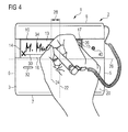
-
zeigt eine Draufsicht der von einem Rechtshänder benutzten beispielhaften Ausführungsform der erfindungsgemäßen Vorrichtung gemäß der
Fig. 1 ,shows a plan view of the example used by a right-handed exemplary embodiment of the inventive device according to theFig. 1 . - Fig. 5Fig. 5
-
zeigt eine Draufsicht der von einem Linkshänder benutzten beispielhaften Ausführungsform der erfindungsgemäßen Vorrichtung gemäß der
Fig. 2 ,shows a plan view of the example used by a left-handed exemplary embodiment of the device according to the invention according to theFig. 2 . - Fig. 6Fig. 6
-
zeigt eine Draufsicht der in der
Fig. 1 und2 gezeigten Vorrichtung zur elektronischen Erfassung einer Benutzereingabe wie beispielsweise eine Unterschrift, wobei das vordere Gehäuseteil entfernt ist und die einzelnen Baugruppen, die im Gehäuseinneren untergebracht sind, ersichtlich sind,shows a plan view of the in theFig. 1 and2 a device for electronically detecting a user input, such as a signature, shown, wherein the front housing part is removed and the individual components which are accommodated inside the housing are visible, - Fig. 7Fig. 7
-
zeigt eine perspektivische Ansicht eines Gehäuserückteils der in den
Fig. 1 und2 gezeigten Vorrichtung gemäß der vorliegenden Erfindung,shows a perspective view of a housing back of the in theFig. 1 and2 shown device according to the present invention, - Fig. 8Fig. 8
-
zeigt eine perspektivische Ansicht der Innenseite des Gehäusevorderteils der in den
Fig. 1 und2 gezeigten Vorrichtung gemäß der vorliegenden Erfindung,shows a perspective view of the inside of the housing front part of the in theFig. 1 and2 shown device according to the present invention, - Fig. 9Fig. 9
- zeigt eine Vorderansicht einer weiteren beispielhaften Ausführungsform einer erfindungsgemäßen Vorrichtung zur elektronischen Erfassung einer Benutzereingabe wie beispielsweise eine Unterschrift, undshows a front view of another exemplary embodiment of an inventive device for electronically detecting a user input such as a signature, and
- Fig. 10Fig. 10
-
zeigt eine Seitenansicht von rechts der in der
Fig. 9 gezeigten erfindungsgemäßen Vorrichtung.shows a side view from the right in theFig. 9 shown device according to the invention.
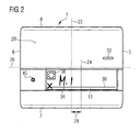
Die in der
Das Gehäuse 2 hat in der gezeigten Draufsicht einen rechten Rand 5, einen linken Rand 6, einen unteren Rand 7 und einen oberen Rand 8. diese Nomenklatur für die Ränder 5-8 des Gehäuses 2 kann ohne weiteres auch auf die Ränder der Rechtecköffnung verwendet werden.The
Das Eingabefeld 13 ist von an sich bekannter Bauart, so dass grundsätzlich keine weiteren Erläuterungen zu dessen Aufbau und Funktionsweise notwendig sind. Der guten Ordnung halber wird auf bisherige Veröffentlichungen der StepOver GmbH / Deutschland verwiesen, die beispielsweise unter den Markennamen: blueMobile Pad, plusPad, blueM Pad und +Pad II/III sogenannte Signaturpads mit entsprechendem Eingabefeld vertreibt. Das Eingabefeld 13 kann in Form einer Abtastvorrichtung ausgebildet sein, die mittels eines Stifts 33, wie er beispielsweise in der
Wie in der
Die Betriebsbereitschaft der erfindungsgemäßen Vorrichtung, wie sie in der
Die elektrische Versorgung der in der
Wie in der
Aus der
In der
In beiden Ausführungsformen der
Bei der für einen Linkshänder geeigneten Positionierung der erfindungsgemäßen Vorrichtung 1, wie sie in der
Wie in den
Die
Der Vollständigkeit halber ist in der
Bei der in der
Die größere Ausgestaltung der Handauflagefläche 71 hat den Vorteil, dass eine Person, die eine Unterschrift 34 auf dem Eingabefeld 13 zu leisten hat, sich mit der ganzen Hand auf dem Gehäuse und insbesondere der Handauflagefläche 71 abstützen kann und nicht ein Teil auf dem darunter liegenden Tisch oder dergleichen ablegen muss. Somit kann das Abstützen und Schreiben noch bequemer sein als bei der Ausführungsform gemäß den
Claims (10)
Applications Claiming Priority (1)
| Application Number | Priority Date | Filing Date | Title |
|---|---|---|---|
| US92819407P | 2007-05-08 | 2007-05-08 |
Publications (3)
| Publication Number | Publication Date |
|---|---|
| EP1990709A2 true EP1990709A2 (en) | 2008-11-12 |
| EP1990709A3 EP1990709A3 (en) | 2008-12-03 |
| EP1990709B1 EP1990709B1 (en) | 2010-09-22 |
Family
ID=39645315
Family Applications (1)
| Application Number | Title | Priority Date | Filing Date |
|---|---|---|---|
| EP08003984A Active EP1990709B1 (en) | 2007-05-08 | 2008-03-04 | Device for identifying a hand-written user entry electronically |
Country Status (5)
| Country | Link |
|---|---|
| US (1) | US8378977B2 (en) |
| EP (1) | EP1990709B1 (en) |
| JP (1) | JP2008282395A (en) |
| AT (1) | ATE482423T1 (en) |
| DE (1) | DE502008001356D1 (en) |
Cited By (3)
| Publication number | Priority date | Publication date | Assignee | Title |
|---|---|---|---|---|
| DE102009044138B3 (en) * | 2009-09-30 | 2011-06-16 | Signotec Gmbh | Device e.g. mobile signature pad, for attaching e.g. capacitive touch-sensitive detection panel for detecting user input in laptop, has film glued for attachment of detecting unit in housings, where housings receive detecting unit |
| CN103888260A (en) * | 2014-03-13 | 2014-06-25 | 北京数字认证股份有限公司 | Digital signature device corresponding to handwritten signature reliably |
| EP2662753B1 (en) * | 2012-05-09 | 2018-10-17 | Stepover GmbH | Pen barrel for holding a pen |
Families Citing this family (2)
| Publication number | Priority date | Publication date | Assignee | Title |
|---|---|---|---|---|
| WO2011020178A1 (en) * | 2009-08-17 | 2011-02-24 | Thomas Matthew Mann Gibson | Method, system and computer program for generating authenticated documents |
| ITRM20130579A1 (en) * | 2013-10-21 | 2015-04-22 | Prb S R L | METHOD FOR THE ACQUISITION OF THE NATURAL SIGNATURE BY MEANS OF A DIGITIZING TABLET OF THE ¿TOUCH SCREEN¿ TYPE. |
Citations (4)
| Publication number | Priority date | Publication date | Assignee | Title |
|---|---|---|---|---|
| DE19859932A1 (en) | 1998-12-24 | 2000-06-29 | Soft Edv Gmbh H | Arrangement and method for electronically recording a lettering, in particular a signature |
| US6177926B1 (en) | 1996-10-22 | 2001-01-23 | Intermec Ip Corp. | Hand-held computer having input screen and means for preventing inadvertent actuation of keys |
| US20020129257A1 (en) | 2001-03-07 | 2002-09-12 | Diebold, Incorporated | Automated transaction machine digital signature system and method |
| US20060138228A1 (en) | 2002-10-04 | 2006-06-29 | David Sanders | Recording writing movements |
Family Cites Families (11)
| Publication number | Priority date | Publication date | Assignee | Title |
|---|---|---|---|---|
| USD307134S (en) | 1986-10-17 | 1990-04-10 | Sharp Corporation | Data entry writing pad for electronic filing system |
| CA2006788C (en) | 1988-12-29 | 1999-07-27 | Shigeaki Sano | Portable type data input terminal |
| US5103486A (en) | 1990-04-19 | 1992-04-07 | Grippi Victor J | Fingerprint/signature synthesis |
| JP3190074B2 (en) * | 1991-09-11 | 2001-07-16 | 株式会社東芝 | Handwriting input device |
| DE19811930A1 (en) | 1998-03-19 | 1999-09-23 | Soft Edv Gmbh H | Portable computer for electronic signature detection, esp. a notebook |
| ES2245642T3 (en) | 1999-05-14 | 2006-01-16 | Identcom Gmbh | PORTABLE DATA RECORDING DEVICE FOR DELIVERY. |
| US7479946B2 (en) | 2002-01-11 | 2009-01-20 | Hand Held Products, Inc. | Ergonomically designed multifunctional transaction terminal |
| US6757156B2 (en) | 2002-03-06 | 2004-06-29 | Xybernaut Corporation | Ergonomic hand held display |
| EP1489481A1 (en) * | 2003-06-18 | 2004-12-22 | Identification Systems DERMALOG GmbH | Computer Input device with user identification |
| USD532009S1 (en) | 2005-11-07 | 2006-11-14 | Topaz Systems, Inc. | Integrated signature pad and fingerprint reader |
| DE102006000859A1 (en) | 2006-01-05 | 2007-07-19 | Stepover Gmbh | Device and method for detecting a signature |
-
2008
- 2008-03-04 DE DE502008001356T patent/DE502008001356D1/en active Active
- 2008-03-04 EP EP08003984A patent/EP1990709B1/en active Active
- 2008-03-04 AT AT08003984T patent/ATE482423T1/en active
- 2008-04-30 JP JP2008119370A patent/JP2008282395A/en not_active Withdrawn
- 2008-05-07 US US12/151,523 patent/US8378977B2/en active Active
Patent Citations (4)
| Publication number | Priority date | Publication date | Assignee | Title |
|---|---|---|---|---|
| US6177926B1 (en) | 1996-10-22 | 2001-01-23 | Intermec Ip Corp. | Hand-held computer having input screen and means for preventing inadvertent actuation of keys |
| DE19859932A1 (en) | 1998-12-24 | 2000-06-29 | Soft Edv Gmbh H | Arrangement and method for electronically recording a lettering, in particular a signature |
| US20020129257A1 (en) | 2001-03-07 | 2002-09-12 | Diebold, Incorporated | Automated transaction machine digital signature system and method |
| US20060138228A1 (en) | 2002-10-04 | 2006-06-29 | David Sanders | Recording writing movements |
Cited By (4)
| Publication number | Priority date | Publication date | Assignee | Title |
|---|---|---|---|---|
| DE102009044138B3 (en) * | 2009-09-30 | 2011-06-16 | Signotec Gmbh | Device e.g. mobile signature pad, for attaching e.g. capacitive touch-sensitive detection panel for detecting user input in laptop, has film glued for attachment of detecting unit in housings, where housings receive detecting unit |
| EP2662753B1 (en) * | 2012-05-09 | 2018-10-17 | Stepover GmbH | Pen barrel for holding a pen |
| CN103888260A (en) * | 2014-03-13 | 2014-06-25 | 北京数字认证股份有限公司 | Digital signature device corresponding to handwritten signature reliably |
| CN103888260B (en) * | 2014-03-13 | 2017-11-14 | 北京数字认证股份有限公司 | One kind can establish reliable corresponding digital signature device with handwriting |
Also Published As
| Publication number | Publication date |
|---|---|
| EP1990709B1 (en) | 2010-09-22 |
| JP2008282395A (en) | 2008-11-20 |
| US20080277170A1 (en) | 2008-11-13 |
| EP1990709A3 (en) | 2008-12-03 |
| US8378977B2 (en) | 2013-02-19 |
| DE502008001356D1 (en) | 2010-11-04 |
| ATE482423T1 (en) | 2010-10-15 |
Similar Documents
| Publication | Publication Date | Title |
|---|---|---|
| DE112007002130B4 (en) | Computer system indicator panel with exposed indicator edge | |
| AT507762B1 (en) | DEVICE FOR PROTECTING MONEY OUTPUT AUTOMATES | |
| DE202007002776U1 (en) | Device for detecting an object | |
| EP1990709B1 (en) | Device for identifying a hand-written user entry electronically | |
| DE69727091T2 (en) | Portable calculator | |
| CH641099A5 (en) | CONTAINER AGGREGATE SUITABLE FOR INSTALLATION ON A LEVEL SURFACE, e.g. DESK TOP. | |
| DE202012102459U1 (en) | Electronic torque wrench | |
| DE202007018958U1 (en) | touch screen | |
| DE102018130600A1 (en) | Magnetic privacy filter | |
| EP2662753B1 (en) | Pen barrel for holding a pen | |
| DE102011001324A1 (en) | Device for attaching a tablet computer to a VESA mount | |
| DE10149743B4 (en) | server | |
| DE102005045637B3 (en) | Notebook computer, has housing and motherboard and housing has opening in which USB port is arranged, which is electrically connected with motherboard and opening is designed on housing plane of notebook-keyboard | |
| EP2560148B1 (en) | Device for the mounting of peripheral devices to automated check-out systems | |
| DE102018009011A1 (en) | Lottery or cash register terminal | |
| EP3884481B1 (en) | Smartboard and set for digitalizing workshop results | |
| DE202005019325U1 (en) | Side part for dartboard has side part, which can be attached to edge of dartboard by means of which dartboard can have different forms whereby one projection of side part attaches it to recess of dartboard | |
| EP2801288A1 (en) | Sheet music holder, in particular for portable musical instruments | |
| DE102005004028A1 (en) | Three pin DIN-socket cover for electronic device e.g. keyboard, has fixing section including fixing spikes and inserted into DIN-socket, and cylindrical cover section connected with fixing section such that cover is fixed at socket | |
| DE102013104125B4 (en) | Portable computer with a housing base part and a housing cover part | |
| DE202006002456U1 (en) | Climbing route marking device for climbing wall has information carrier fastened to the climbing projection which is fixed on climbing wall | |
| DE102010004813A1 (en) | Multimedia reproducing apparatus for use with e.g. photo album, has retention device attached and/or sticked on cover and/or pages of printed product, and action board rotatably secured at retention device over ball joint | |
| DE4418255A1 (en) | Multi-functional domestic remote control device | |
| DE3511601A1 (en) | Signal-processing device | |
| DE3318227A1 (en) | Keyboard for a typewriter |
Legal Events
| Date | Code | Title | Description |
|---|---|---|---|
| PUAI | Public reference made under article 153(3) epc to a published international application that has entered the european phase |
Free format text: ORIGINAL CODE: 0009012 |
|
| AK | Designated contracting states |
Kind code of ref document: A2 Designated state(s): AT BE BG CH CY CZ DE DK EE ES FI FR GB GR HR HU IE IS IT LI LT LU LV MC MT NL NO PL PT RO SE SI SK TR |
|
| AX | Request for extension of the european patent |
Extension state: AL BA MK RS |
|
| PUAL | Search report despatched |
Free format text: ORIGINAL CODE: 0009013 |
|
| AK | Designated contracting states |
Kind code of ref document: A3 Designated state(s): AT BE BG CH CY CZ DE DK EE ES FI FR GB GR HR HU IE IS IT LI LT LU LV MC MT NL NO PL PT RO SE SI SK TR |
|
| AX | Request for extension of the european patent |
Extension state: AL BA MK RS |
|
| 17P | Request for examination filed |
Effective date: 20081107 |
|
| 17Q | First examination report despatched |
Effective date: 20090309 |
|
| AKX | Designation fees paid |
Designated state(s): AT BE BG CH CY CZ DE DK EE ES FI FR GB GR HR HU IE IS IT LI LT LU LV MC MT NL NO PL PT RO SE SI SK TR |
|
| GRAP | Despatch of communication of intention to grant a patent |
Free format text: ORIGINAL CODE: EPIDOSNIGR1 |
|
| GRAS | Grant fee paid |
Free format text: ORIGINAL CODE: EPIDOSNIGR3 |
|
| GRAA | (expected) grant |
Free format text: ORIGINAL CODE: 0009210 |
|
| AK | Designated contracting states |
Kind code of ref document: B1 Designated state(s): AT BE BG CH CY CZ DE DK EE ES FI FR GB GR HR HU IE IS IT LI LT LU LV MC MT NL NO PL PT RO SE SI SK TR |
|
| REG | Reference to a national code |
Ref country code: GB Ref legal event code: FG4D Free format text: NOT ENGLISH |
|
| REG | Reference to a national code |
Ref country code: CH Ref legal event code: EP |
|
| REG | Reference to a national code |
Ref country code: IE Ref legal event code: FG4D Free format text: LANGUAGE OF EP DOCUMENT: GERMAN |
|
| REF | Corresponds to: |
Ref document number: 502008001356 Country of ref document: DE Date of ref document: 20101104 Kind code of ref document: P |
|
| PG25 | Lapsed in a contracting state [announced via postgrant information from national office to epo] |
Ref country code: LT Free format text: LAPSE BECAUSE OF FAILURE TO SUBMIT A TRANSLATION OF THE DESCRIPTION OR TO PAY THE FEE WITHIN THE PRESCRIBED TIME-LIMIT Effective date: 20100922 Ref country code: NO Free format text: LAPSE BECAUSE OF FAILURE TO SUBMIT A TRANSLATION OF THE DESCRIPTION OR TO PAY THE FEE WITHIN THE PRESCRIBED TIME-LIMIT Effective date: 20101222 Ref country code: FI Free format text: LAPSE BECAUSE OF FAILURE TO SUBMIT A TRANSLATION OF THE DESCRIPTION OR TO PAY THE FEE WITHIN THE PRESCRIBED TIME-LIMIT Effective date: 20100922 |
|
| REG | Reference to a national code |
Ref country code: NL Ref legal event code: VDEP Effective date: 20100922 |
|
| LTIE | Lt: invalidation of european patent or patent extension |
Effective date: 20100922 |
|
| PG25 | Lapsed in a contracting state [announced via postgrant information from national office to epo] |
Ref country code: SI Free format text: LAPSE BECAUSE OF FAILURE TO SUBMIT A TRANSLATION OF THE DESCRIPTION OR TO PAY THE FEE WITHIN THE PRESCRIBED TIME-LIMIT Effective date: 20100922 Ref country code: PL Free format text: LAPSE BECAUSE OF FAILURE TO SUBMIT A TRANSLATION OF THE DESCRIPTION OR TO PAY THE FEE WITHIN THE PRESCRIBED TIME-LIMIT Effective date: 20100922 Ref country code: HR Free format text: LAPSE BECAUSE OF FAILURE TO SUBMIT A TRANSLATION OF THE DESCRIPTION OR TO PAY THE FEE WITHIN THE PRESCRIBED TIME-LIMIT Effective date: 20100922 |
|
| PG25 | Lapsed in a contracting state [announced via postgrant information from national office to epo] |
Ref country code: GR Free format text: LAPSE BECAUSE OF FAILURE TO SUBMIT A TRANSLATION OF THE DESCRIPTION OR TO PAY THE FEE WITHIN THE PRESCRIBED TIME-LIMIT Effective date: 20101223 Ref country code: LV Free format text: LAPSE BECAUSE OF FAILURE TO SUBMIT A TRANSLATION OF THE DESCRIPTION OR TO PAY THE FEE WITHIN THE PRESCRIBED TIME-LIMIT Effective date: 20100922 Ref country code: SE Free format text: LAPSE BECAUSE OF FAILURE TO SUBMIT A TRANSLATION OF THE DESCRIPTION OR TO PAY THE FEE WITHIN THE PRESCRIBED TIME-LIMIT Effective date: 20100922 |
|
| REG | Reference to a national code |
Ref country code: IE Ref legal event code: FD4D |
|
| PG25 | Lapsed in a contracting state [announced via postgrant information from national office to epo] |
Ref country code: IE Free format text: LAPSE BECAUSE OF FAILURE TO SUBMIT A TRANSLATION OF THE DESCRIPTION OR TO PAY THE FEE WITHIN THE PRESCRIBED TIME-LIMIT Effective date: 20100922 |
|
| PG25 | Lapsed in a contracting state [announced via postgrant information from national office to epo] |
Ref country code: NL Free format text: LAPSE BECAUSE OF FAILURE TO SUBMIT A TRANSLATION OF THE DESCRIPTION OR TO PAY THE FEE WITHIN THE PRESCRIBED TIME-LIMIT Effective date: 20100922 Ref country code: CZ Free format text: LAPSE BECAUSE OF FAILURE TO SUBMIT A TRANSLATION OF THE DESCRIPTION OR TO PAY THE FEE WITHIN THE PRESCRIBED TIME-LIMIT Effective date: 20100922 Ref country code: RO Free format text: LAPSE BECAUSE OF FAILURE TO SUBMIT A TRANSLATION OF THE DESCRIPTION OR TO PAY THE FEE WITHIN THE PRESCRIBED TIME-LIMIT Effective date: 20100922 Ref country code: EE Free format text: LAPSE BECAUSE OF FAILURE TO SUBMIT A TRANSLATION OF THE DESCRIPTION OR TO PAY THE FEE WITHIN THE PRESCRIBED TIME-LIMIT Effective date: 20100922 Ref country code: IS Free format text: LAPSE BECAUSE OF FAILURE TO SUBMIT A TRANSLATION OF THE DESCRIPTION OR TO PAY THE FEE WITHIN THE PRESCRIBED TIME-LIMIT Effective date: 20110122 Ref country code: IT Free format text: LAPSE BECAUSE OF FAILURE TO SUBMIT A TRANSLATION OF THE DESCRIPTION OR TO PAY THE FEE WITHIN THE PRESCRIBED TIME-LIMIT Effective date: 20100922 Ref country code: PT Free format text: LAPSE BECAUSE OF FAILURE TO SUBMIT A TRANSLATION OF THE DESCRIPTION OR TO PAY THE FEE WITHIN THE PRESCRIBED TIME-LIMIT Effective date: 20110124 Ref country code: SK Free format text: LAPSE BECAUSE OF FAILURE TO SUBMIT A TRANSLATION OF THE DESCRIPTION OR TO PAY THE FEE WITHIN THE PRESCRIBED TIME-LIMIT Effective date: 20100922 |
|
| PG25 | Lapsed in a contracting state [announced via postgrant information from national office to epo] |
Ref country code: ES Free format text: LAPSE BECAUSE OF FAILURE TO SUBMIT A TRANSLATION OF THE DESCRIPTION OR TO PAY THE FEE WITHIN THE PRESCRIBED TIME-LIMIT Effective date: 20110102 |
|
| PLBE | No opposition filed within time limit |
Free format text: ORIGINAL CODE: 0009261 |
|
| STAA | Information on the status of an ep patent application or granted ep patent |
Free format text: STATUS: NO OPPOSITION FILED WITHIN TIME LIMIT |
|
| 26N | No opposition filed |
Effective date: 20110623 |
|
| PG25 | Lapsed in a contracting state [announced via postgrant information from national office to epo] |
Ref country code: DK Free format text: LAPSE BECAUSE OF FAILURE TO SUBMIT A TRANSLATION OF THE DESCRIPTION OR TO PAY THE FEE WITHIN THE PRESCRIBED TIME-LIMIT Effective date: 20100922 |
|
| BERE | Be: lapsed |
Owner name: STEPOVER G.M.B.H. Effective date: 20110331 |
|
| REG | Reference to a national code |
Ref country code: DE Ref legal event code: R097 Ref document number: 502008001356 Country of ref document: DE Effective date: 20110623 |
|
| PG25 | Lapsed in a contracting state [announced via postgrant information from national office to epo] |
Ref country code: MC Free format text: LAPSE BECAUSE OF NON-PAYMENT OF DUE FEES Effective date: 20110331 |
|
| PG25 | Lapsed in a contracting state [announced via postgrant information from national office to epo] |
Ref country code: MT Free format text: LAPSE BECAUSE OF FAILURE TO SUBMIT A TRANSLATION OF THE DESCRIPTION OR TO PAY THE FEE WITHIN THE PRESCRIBED TIME-LIMIT Effective date: 20100922 Ref country code: BE Free format text: LAPSE BECAUSE OF NON-PAYMENT OF DUE FEES Effective date: 20110331 |
|
| REG | Reference to a national code |
Ref country code: CH Ref legal event code: PL |
|
| PG25 | Lapsed in a contracting state [announced via postgrant information from national office to epo] |
Ref country code: LI Free format text: LAPSE BECAUSE OF NON-PAYMENT OF DUE FEES Effective date: 20120331 Ref country code: CH Free format text: LAPSE BECAUSE OF NON-PAYMENT OF DUE FEES Effective date: 20120331 |
|
| PG25 | Lapsed in a contracting state [announced via postgrant information from national office to epo] |
Ref country code: LU Free format text: LAPSE BECAUSE OF NON-PAYMENT OF DUE FEES Effective date: 20110304 Ref country code: CY Free format text: LAPSE BECAUSE OF FAILURE TO SUBMIT A TRANSLATION OF THE DESCRIPTION OR TO PAY THE FEE WITHIN THE PRESCRIBED TIME-LIMIT Effective date: 20100922 |
|
| PG25 | Lapsed in a contracting state [announced via postgrant information from national office to epo] |
Ref country code: BG Free format text: LAPSE BECAUSE OF FAILURE TO SUBMIT A TRANSLATION OF THE DESCRIPTION OR TO PAY THE FEE WITHIN THE PRESCRIBED TIME-LIMIT Effective date: 20101222 Ref country code: TR Free format text: LAPSE BECAUSE OF FAILURE TO SUBMIT A TRANSLATION OF THE DESCRIPTION OR TO PAY THE FEE WITHIN THE PRESCRIBED TIME-LIMIT Effective date: 20100922 |
|
| PG25 | Lapsed in a contracting state [announced via postgrant information from national office to epo] |
Ref country code: HU Free format text: LAPSE BECAUSE OF FAILURE TO SUBMIT A TRANSLATION OF THE DESCRIPTION OR TO PAY THE FEE WITHIN THE PRESCRIBED TIME-LIMIT Effective date: 20100922 |
|
| REG | Reference to a national code |
Ref country code: AT Ref legal event code: MM01 Ref document number: 482423 Country of ref document: AT Kind code of ref document: T Effective date: 20130304 |
|
| PG25 | Lapsed in a contracting state [announced via postgrant information from national office to epo] |
Ref country code: AT Free format text: LAPSE BECAUSE OF NON-PAYMENT OF DUE FEES Effective date: 20130304 |
|
| REG | Reference to a national code |
Ref country code: FR Ref legal event code: PLFP Year of fee payment: 9 |
|
| REG | Reference to a national code |
Ref country code: FR Ref legal event code: PLFP Year of fee payment: 10 |
|
| REG | Reference to a national code |
Ref country code: FR Ref legal event code: PLFP Year of fee payment: 11 |
|
| PGFP | Annual fee paid to national office [announced via postgrant information from national office to epo] |
Ref country code: FR Payment date: 20230320 Year of fee payment: 16 |
|
| PGFP | Annual fee paid to national office [announced via postgrant information from national office to epo] |
Ref country code: GB Payment date: 20230323 Year of fee payment: 16 Ref country code: DE Payment date: 20230308 Year of fee payment: 16 |
|
| REG | Reference to a national code |
Ref country code: DE Ref legal event code: R082 Ref document number: 502008001356 Country of ref document: DE Representative=s name: ALPSPITZ IP ALLGAYER UND PARTNER PATENTANWAELT, DE |