EP1991432B1 - Distance indicating system and method - Google Patents
Distance indicating system and method Download PDFInfo
- Publication number
- EP1991432B1 EP1991432B1 EP07716847.4A EP07716847A EP1991432B1 EP 1991432 B1 EP1991432 B1 EP 1991432B1 EP 07716847 A EP07716847 A EP 07716847A EP 1991432 B1 EP1991432 B1 EP 1991432B1
- Authority
- EP
- European Patent Office
- Prior art keywords
- transceiver
- electromagnetic wave
- distance
- operative
- antenna
- Prior art date
- Legal status (The legal status is an assumption and is not a legal conclusion. Google has not performed a legal analysis and makes no representation as to the accuracy of the status listed.)
- Active
Links
- 238000000034 method Methods 0.000 title claims description 13
- 238000004891 communication Methods 0.000 claims description 38
- 239000012530 fluid Substances 0.000 claims description 33
- 238000012545 processing Methods 0.000 claims description 31
- 230000001939 inductive effect Effects 0.000 claims description 7
- 230000008878 coupling Effects 0.000 claims description 2
- 238000010168 coupling process Methods 0.000 claims description 2
- 238000005859 coupling reaction Methods 0.000 claims description 2
- 239000000725 suspension Substances 0.000 description 15
- 239000004020 conductor Substances 0.000 description 11
- 230000000712 assembly Effects 0.000 description 9
- 238000000429 assembly Methods 0.000 description 9
- 230000001143 conditioned effect Effects 0.000 description 9
- 239000006096 absorbing agent Substances 0.000 description 3
- 238000010276 construction Methods 0.000 description 3
- 230000004044 response Effects 0.000 description 3
- 230000035939 shock Effects 0.000 description 3
- 230000001133 acceleration Effects 0.000 description 2
- 230000008859 change Effects 0.000 description 2
- 238000004519 manufacturing process Methods 0.000 description 2
- 238000005259 measurement Methods 0.000 description 2
- 239000000853 adhesive Substances 0.000 description 1
- 230000001070 adhesive effect Effects 0.000 description 1
- 230000008901 benefit Effects 0.000 description 1
- 238000013016 damping Methods 0.000 description 1
- 230000001419 dependent effect Effects 0.000 description 1
- 238000013461 design Methods 0.000 description 1
- 230000007613 environmental effect Effects 0.000 description 1
- 238000007689 inspection Methods 0.000 description 1
- 238000012544 monitoring process Methods 0.000 description 1
- 238000000465 moulding Methods 0.000 description 1
- 230000002093 peripheral effect Effects 0.000 description 1
- 230000010363 phase shift Effects 0.000 description 1
- 230000008569 process Effects 0.000 description 1
- 150000003839 salts Chemical class 0.000 description 1
- 239000004065 semiconductor Substances 0.000 description 1
- 238000012546 transfer Methods 0.000 description 1
- 238000013022 venting Methods 0.000 description 1
- XLYOFNOQVPJJNP-UHFFFAOYSA-N water Substances O XLYOFNOQVPJJNP-UHFFFAOYSA-N 0.000 description 1
Images

Classifications
-
- B—PERFORMING OPERATIONS; TRANSPORTING
- B60—VEHICLES IN GENERAL
- B60G—VEHICLE SUSPENSION ARRANGEMENTS
- B60G17/00—Resilient suspensions having means for adjusting the spring or vibration-damper characteristics, for regulating the distance between a supporting surface and a sprung part of vehicle or for locking suspension during use to meet varying vehicular or surface conditions, e.g. due to speed or load
- B60G17/015—Resilient suspensions having means for adjusting the spring or vibration-damper characteristics, for regulating the distance between a supporting surface and a sprung part of vehicle or for locking suspension during use to meet varying vehicular or surface conditions, e.g. due to speed or load the regulating means comprising electric or electronic elements
- B60G17/019—Resilient suspensions having means for adjusting the spring or vibration-damper characteristics, for regulating the distance between a supporting surface and a sprung part of vehicle or for locking suspension during use to meet varying vehicular or surface conditions, e.g. due to speed or load the regulating means comprising electric or electronic elements characterised by the type of sensor or the arrangement thereof
- B60G17/01933—Velocity, e.g. relative velocity-displacement sensors
-
- B—PERFORMING OPERATIONS; TRANSPORTING
- B60—VEHICLES IN GENERAL
- B60G—VEHICLE SUSPENSION ARRANGEMENTS
- B60G17/00—Resilient suspensions having means for adjusting the spring or vibration-damper characteristics, for regulating the distance between a supporting surface and a sprung part of vehicle or for locking suspension during use to meet varying vehicular or surface conditions, e.g. due to speed or load
- B60G17/02—Spring characteristics, e.g. mechanical springs and mechanical adjusting means
- B60G17/04—Spring characteristics, e.g. mechanical springs and mechanical adjusting means fluid spring characteristics
- B60G17/052—Pneumatic spring characteristics
-
- F—MECHANICAL ENGINEERING; LIGHTING; HEATING; WEAPONS; BLASTING
- F16—ENGINEERING ELEMENTS AND UNITS; GENERAL MEASURES FOR PRODUCING AND MAINTAINING EFFECTIVE FUNCTIONING OF MACHINES OR INSTALLATIONS; THERMAL INSULATION IN GENERAL
- F16F—SPRINGS; SHOCK-ABSORBERS; MEANS FOR DAMPING VIBRATION
- F16F9/00—Springs, vibration-dampers, shock-absorbers, or similarly-constructed movement-dampers using a fluid or the equivalent as damping medium
- F16F9/02—Springs, vibration-dampers, shock-absorbers, or similarly-constructed movement-dampers using a fluid or the equivalent as damping medium using gas only or vacuum
- F16F9/04—Springs, vibration-dampers, shock-absorbers, or similarly-constructed movement-dampers using a fluid or the equivalent as damping medium using gas only or vacuum in a chamber with a flexible wall
- F16F9/05—Springs, vibration-dampers, shock-absorbers, or similarly-constructed movement-dampers using a fluid or the equivalent as damping medium using gas only or vacuum in a chamber with a flexible wall the flexible wall being of the rolling diaphragm type
-
- G—PHYSICS
- G01—MEASURING; TESTING
- G01S—RADIO DIRECTION-FINDING; RADIO NAVIGATION; DETERMINING DISTANCE OR VELOCITY BY USE OF RADIO WAVES; LOCATING OR PRESENCE-DETECTING BY USE OF THE REFLECTION OR RERADIATION OF RADIO WAVES; ANALOGOUS ARRANGEMENTS USING OTHER WAVES
- G01S13/00—Systems using the reflection or reradiation of radio waves, e.g. radar systems; Analogous systems using reflection or reradiation of waves whose nature or wavelength is irrelevant or unspecified
- G01S13/74—Systems using reradiation of radio waves, e.g. secondary radar systems; Analogous systems
- G01S13/82—Systems using reradiation of radio waves, e.g. secondary radar systems; Analogous systems wherein continuous-type signals are transmitted
- G01S13/825—Systems using reradiation of radio waves, e.g. secondary radar systems; Analogous systems wherein continuous-type signals are transmitted with exchange of information between interrogator and responder
-
- B—PERFORMING OPERATIONS; TRANSPORTING
- B60—VEHICLES IN GENERAL
- B60G—VEHICLE SUSPENSION ARRANGEMENTS
- B60G2202/00—Indexing codes relating to the type of spring, damper or actuator
- B60G2202/10—Type of spring
- B60G2202/15—Fluid spring
- B60G2202/152—Pneumatic spring
-
- B—PERFORMING OPERATIONS; TRANSPORTING
- B60—VEHICLES IN GENERAL
- B60G—VEHICLE SUSPENSION ARRANGEMENTS
- B60G2204/00—Indexing codes related to suspensions per se or to auxiliary parts
- B60G2204/10—Mounting of suspension elements
- B60G2204/11—Mounting of sensors thereon
- B60G2204/111—Mounting of sensors thereon on pneumatic springs
-
- B—PERFORMING OPERATIONS; TRANSPORTING
- B60—VEHICLES IN GENERAL
- B60G—VEHICLE SUSPENSION ARRANGEMENTS
- B60G2400/00—Indexing codes relating to detected, measured or calculated conditions or factors
- B60G2400/25—Stroke; Height; Displacement
- B60G2400/252—Stroke; Height; Displacement vertical
-
- B—PERFORMING OPERATIONS; TRANSPORTING
- B60—VEHICLES IN GENERAL
- B60G—VEHICLE SUSPENSION ARRANGEMENTS
- B60G2401/00—Indexing codes relating to the type of sensors based on the principle of their operation
- B60G2401/17—Magnetic/Electromagnetic
- B60G2401/174—Radar
-
- B—PERFORMING OPERATIONS; TRANSPORTING
- B60—VEHICLES IN GENERAL
- B60G—VEHICLE SUSPENSION ARRANGEMENTS
- B60G2401/00—Indexing codes relating to the type of sensors based on the principle of their operation
- B60G2401/17—Magnetic/Electromagnetic
- B60G2401/176—Radio or audio sensitive means, e.g. Ultrasonic
-
- F—MECHANICAL ENGINEERING; LIGHTING; HEATING; WEAPONS; BLASTING
- F16—ENGINEERING ELEMENTS AND UNITS; GENERAL MEASURES FOR PRODUCING AND MAINTAINING EFFECTIVE FUNCTIONING OF MACHINES OR INSTALLATIONS; THERMAL INSULATION IN GENERAL
- F16F—SPRINGS; SHOCK-ABSORBERS; MEANS FOR DAMPING VIBRATION
- F16F2230/00—Purpose; Design features
- F16F2230/08—Sensor arrangement
Definitions
- the present novel concept broadly relates to the art of distance measurement and, more particularly, to a system and method for indicating the distance between associated structural members using electromagnetic wave modulation in an air spring system.
- the subject system and method are amenable to broad use in a wide variety of applications and environments.
- One example of a suitable application is the use of the subject system and method on and with an associated fluid suspension member, such as an air spring of a vehicle, for example.
- the subject system and method will be discussed in detail hereinafter with specific reference to use on such an associated fluid suspension member.
- the subject system and method are capable of broader application and are not intended to be limited to the specific examples shown and discussed herein, which are merely examples of suitable applications.
- a variety of well known and commonly used devices and arrangements have been and are currently used to monitor the relative position of one structural member to another.
- mechanical linkage sensors that include one or more linkage members are often used to connect between adjacent structural members, such as a suspension component of a vehicle and the corresponding frame or body of the same.
- the linkage members typically act through a variable resistor or other suitable component that changes in response to the movement of the linkage.
- An electronic control unit (ECU) or other suitable device determines the relative position of one structural member to the other based upon a corresponding change in voltage across the variable resistor or a corresponding change in current through the resistor.
- ECU electronice control unit
- mechanical linkage sensors Another problem with mechanical linkage sensors is that the electronic components thereof are typically exposed to harsh environmental conditions (e.g., temperature extremes, water, dirt, salt) normally experienced by a vehicle traveling along a roadway. As a result of such exposure, the electronic components of the sensors can become corroded and fail to function properly. Due to one or both of these or other problems, one or more of the mechanical linkage sensors may be non-operational at any given time. Thus, regular inspection and replacement of such sensors is typically required.
- harsh environmental conditions e.g., temperature extremes, water, dirt, salt
- non-contact sensors that utilize sound or pressure waves traveling through a fluid medium, typically at an ultrasonic frequency, have been used in determining the relative position of one structural member to another.
- a fluid suspension member such as an air spring.
- the ultrasonic sensor is supported on one end member of the air spring and sends ultrasonic waves through the spring chamber of the air spring toward the opposing end member. The waves are reflected back by a suitable feature of the opposing end member and the distance therebetween is determined in a conventional manner.
- ultrasonic sensor is at least partially sheltered from impacts and exposure.
- numerous disadvantages also exist with the use of ultrasonic sensors.
- One such disadvantage is that such sensors are relatively expensive which tends to undesirably increase production costs.
- the replacement cost of a sensor that does get damaged by an impact or from exposure is likewise increased.
- ultrasonic sensors require a target that is suitable to reflect the ultrasonic waves back to the sensor for determining the distance therebetween. If such a target is not provided, the ultrasonic waves will not be reflected back properly and, thus, a correct determination of distance will not be possible. Thus, a target area must be provided for the proper operation of ultrasonic sensors. This can be particularly problematic, however, where the design constraints of a product limit the possibilities for including a target area. This is also a problem for existing products are being outfitted with ultrasonic sensors, where the existing products do not have a suitable target area.
- An air spring according to the preamble of independent claim 1 is known from DE 197 01 530 C1 .
- a similar air spring assemblies are known from WO 2006/073717 A1 and WO 2006/115747 A2 which, however, only constitute state of the art under Art. 54(3), (4) EPC.
- an air spring assembly as defined in independent claim 1 and a method of determining a distance between first and second end members of an air spring as defined in independent claim 5 are provided.
- the dependent claims define preferred or advantageous embodiments of the invention.
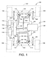
- FIGURE 1 illustrates a vehicle 100 having a sprung mass, such as a vehicle body 102 , for example, and an unsprung mass, such as axles 104 and wheels 106 , for example.
- a plurality of damping members such as shock absorbers 108 , for example, are secured between the sprung and unsprung masses of the vehicle in a suitable manner.
- a plurality of fluid spring members such as air spring assemblies 110 , for example, are disposed between the sprung and unsprung masses of the vehicle adjacent wheels 106 and shock absorbers 108.
- Vehicle 100 also includes a fluid supply system 112 that is in communication with air spring assemblies 110 and is operative to selectively supply and exhaust pressurized fluid therefrom.
- Fluid supply system 112 includes a pressurized fluid source, such as a compressor 114 , and can optionally include a storage vessel, such as reservoir 116 , for example, for receiving and storing pressurized fluid from the pressurized fluid source.
- System 112 can further include a suitable fluid exhaust, such as a muffler 118 , for example, for venting pressurized fluid from the system.
- Fluid supply system 112 can be in communication with the fluid spring members in any suitable manner.
- system 112 can include a valve assembly 120 or other suitable device or arrangement for selectively distributing pressurized fluid between the pressurized fluid source or sources and the fluid spring members.
- compressor 114 , reservoir 116 and muffler 118 are in fluid communication with valve assembly 120.
- air spring assemblies 110 are in fluid communication with valve assembly 120 via fluid lines 122.
- valve assembly 120 can be selectively actuated to transfer pressurized fluid from the compressor and/or reservoir to one or more of the air spring assemblies.
- valve assembly 120 can be selectively actuated to exhaust pressurized fluid from one or more of the air spring assemblies by way of muffler 118 or another suitable arrangement. It will be appreciated that the foregoing fluid supply system and operation thereof are merely exemplary and that any other suitable fluid source, system and/or method of operation can alternately be used.
- Vehicle 100 also includes a suspension control system 124 for selectively operating one or more suspension system components, such as shock absorbers 108 , air spring assemblies 110 and/or pressurized fluid supply system 112 , for example.
- Suspension control system 124 includes an electronic control unit 126 in communication with one or more components of valve assembly 120 , such as through a communication line 128 , for example, for selective actuation and/or operation thereof. Additionally, electronic control unit 126 is in communication with air spring assemblies 110 in a suitable manner, such as through communication lines 130 , for example.
- Suspension control systems such as control system 124 , for example, are operable in a wide variety of manners.
- suspension control systems such as control system 124 , for example, can be used for height adjustment (i.e., to selectively raise or lower the sprung mass of a vehicle).
- suspension control systems such as control system 124 , for example, can be used for leveling operations (i.e., to maintain the sprung mass of a vehicle in a substantially level orientation).
- suspension control systems typically utilize one or more height or distance sensors to monitor the vehicle height and/or orientation.
- a wide variety of height sensors and/or distance determining devices are known and commonly used, as discussed in one of the foregoing sections hereof.
- air spring assemblies 110 include distance indicating systems in accordance with the present novel concept that transmit electromagnetic waves 132 and 134 to determine and communicate a height of the vehicle or distance between two vehicle or suspension system components.
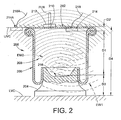
- FIGURE 2 One exemplary embodiment of a fluid suspension member in accordance with the present novel concept is shown in FIGURE 2 as air spring assembly 200 that includes a first or upper end member 202 , a second or lower end member 204 and a flexible spring wall 206 secured therebetween.
- First or upper end member 202 is shown disposed along an associated upper vehicle component UVC and second or lower end member 204 is shown disposed along an associated lower vehicle component LVC .
- the upper and lower vehicle components could, for example, be parts of or associated with the respective sprung and unsprung masses of the vehicle.
- the first and second end members can be respectively secured on the upper and lower vehicle components in any suitable manner, such as by using fasteners (not shown), for example.
- air spring assembly 200 is shown in FIGURE 2 of a rolling-lobe construction. It is to be understood, however, that this construction is merely exemplary and that any other suitable construction can alternately be used.
- Flexible spring wall 206 at least partially defines a spring chamber 208 extending between end members 202 and 204 .
- a suitable fluid line FLN such as one of fluid lines 122 in FIGURE 1 , for example, is in communication with spring chamber 208 through an opening formed through one of the end members of the air spring assembly, such as passage 210 formed through first end member 202 , for example.
- a suitable connector or fitting 212 can be used to maintain fluid line FLN in operative association with spring chamber 208 through passage 210 .
- Air spring assembly 200 also includes a distance indicating system (not numbered) that includes a first transceiver 214 and a second transceiver 216 spaced a distance D1 from the first transceiver.
- First transceiver 214 can be in communication with one or more devices or components through a conductive lead 218 .
- conductive lead 218 can be representative of communication line 130 in FIGURE 1 extending between an air spring assembly 110 and electronic control unit 126 .
- electrical power can be supplied from an external power source (not shown), such as a battery or vehicle alternator, for example.
- second transceiver 216 is preferably wireless. Thus, communication to and from second transceiver 216 occurs using a first electromagnetic wave EW1 and a second electromagnetic wave EW2.
- first transceiver 214 is supported on first end member 202 and second transceiver 216 is supported on second end member 204 .
- the first and second transceivers can be secured on the end members in any suitable manner, such as by using suitable fasteners, adhesives, bracketry or by manufacturing (e.g., molding) a transceiver or component thereof into or onto the end member. Additionally, it is to be understood that such an arrangement is merely exemplary and that any components of a distance indicating system in accordance with the present novel concept can be mounting in other positions, orientations and/or arrangements.
- first and second transceivers can be used in a non-aligned orientation. That is, in the exemplary embodiment shown in FIGURE 2 , second transceiver 216 is disposed approximately centrally on the second end member whereas first transceiver 214 is disposed outwardly toward a peripheral edge of the first end member.
- first transceiver 214 could optionally include a second portion 214A that is separately mountable from the first portion and in communication with one or more other devices or components through a conductive lead 218A .
- the first portion could be a transmitting portion and the second portion could be a receiving portion.
- any other suitable configuration, arrangement or method of operation could alternately be used.
- distance D2 between first transceiver 214 and first end member 202 and distance D3 between second transceiver 216 and second end member 204 will normally be fixed distances.
- the distance between the transceivers which is represented by dimension D1 in FIGURE 2
- the distance between the transceivers can also be representative of the height of air spring assembly 200, as indicated by dimension D4 , and that other dimensions or distances could be similarly determined.
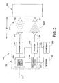
- a distance indicating system 300 is schematically illustrated in FIGURE 3 and includes a first transceiver 302 and a second transceiver 304 spaced a distance D1 from first transceiver 302 .
- First transceiver 302 is in communication with a suitable external power source, such as a battery or an alternator of a vehicle, for example, through a conductive lead 306 .
- first transceiver 302 can be in communication with one or more other systems and/or components 308 , such as through a suitable conductive lead 310 , for example.
- First transceiver 302 includes a transmitter 312 and a first antenna 314 in communication with the transmitter. Suitably conditioned electrical power can be provided to transmitter 312 from an external power source (not shown) through lead 306. Alternately, first transceiver 302 can include a power supply circuit 316 in communication with conductive lead 306 for receiving electrical energy from a suitable electrical power source. Circuit 316 can output conditioned electrical power of appropriate voltages and/or current levels for use and operation of other components of transceiver 302 . For example, power supply circuit 316 is shown in FIGURE 3 in electrical communication with transmitter 312 and provides conditioned electrical power thereto.
- Transmitter 312 is operative to output a carrier wave signal that is broadcast as a first electromagnetic wave EW1 using first antenna 314 .
- Transceiver 302 also includes a receiver 318 in electrical communication with power supply circuit 316 and a second antenna 320 in electrical communication with receiver 318.
- Second transceiver 304 includes a first antenna 322 operative to receive first electromagnetic wave EW1 .
- the second transceiver also includes a second antenna 324 operative to transmit a second electromagnetic wave EW2 , which is received at second antenna 320 of first transceiver 302 and communicated to receiver 318 thereof.
- Second transceiver 304 can generate a modulation signal corresponding to an input acting on an associated component of the distance indicating system, such as a structural component upon which the second transceiver is supported, for example, and utilize the modulation signal to modulate a characteristic, such as frequency or amplitude, for example, of second electromagnetic wave EW2 .
- the receiver is operative to recover a modulating signal from the second electromagnetic wave and generate an output signal related thereto to other devices and/or systems in a suitable manner, such as to component or device 308 through conductive lead 310, for example.
- first transceiver 302 can include a processing device 326 in communication withpower supply circuit 316 that receives conditioned electrical power therefrom. Additionally, processing device 326 is in electrical communication with receiver 318 and can receive the output signal generated thereby. The processing device can then decode or translate the output signal into data and/or other information, such as data related to a distance, acceleration value, temperature level, pressure level or other input, for example. The data and/or other information can be communicated to other devices or systems, such as a system or vehicle network 328 through a conductive lead 330 , for example.
- first electromagnetic wave EW1 is transmitted from first transceiver 302 using first antenna 314 and is received by first antenna 322 of second transceiver 304.
- first antenna 322 of second transceiver 304 includes an inductive element (not shown) or other suitable feature or component, and first electromagnetic wave EW1 induces an electrical output across or along this inductive element to provide electrical power to second transceiver 304 .
- a separate electrical power source could be provided on second transceiver 304 to provide electrical power thereto, rather than utilizing inductive coupling with first transceiver 302.
- the distance of travel of first electromagnetic wave EW1 i.e., the distance D1 between the first and second transceivers
- the distance D1 between the first and second transceivers can be determined by the second transceiver and communicated to the first transceiver or another component.
- a signal corresponding to the distance of travel of first electromagnetic wave EW1 and/or other data or information can be communicated from the second transceiver to a suitable device or component for receiving wave EW1 and determining the distance and/or other data or information therefrom, such suitable components can include receiver 318 and/or processing device 326 of the first transceiver, for example.
- Transmitting portion 402 includes a transmitter 408 and an antenna 410 in communication with the transmitter, which is operative to generate a carrier wave signal that is broadcast as a first electromagnetic wave EW1 using antenna 410 .
- Transmitter 408 can receive conditioned electrical power from an external power source through a suitable conductive lead, such as lead 412 , for example.
- transmitting portion 402 can include a power supply circuit 414 that can receive electrical power from an external power source and output conditioned electrical power to transmitter 408 .
- Receiving portion 404 includes a receiver 416 and an antenna 418 in electrical communication with receiver 416 .
- Conditioned electrical power can be provided from an external electrical power source through a conductive lead, such as lead 420 , for example.
- a power supply circuit 422 can be included on receiving portion 404 that can receive electrical power from an external power source and output conditioned electrical power to the receiver.
- Receiver 416 is shown in FIGURE 4 as being in electrical communication with a component or device 424 through a conductive lead 426 , and is operative to output communication signals thereto.
- a processing device 428 can be included on receiving portion 404 that is in electrical communication with power supply circuit 422 and receiver 416 .
- Processing device 428 can be operative to output data, signals and/or other information to other components or systems, such as a vehicle or system network 430 , for example, through a suitable connecting device, such as conductive lead 432 , for example.
- Transceiver 406 is shown in FIGURE 4 as being spaced a distance D1 from transmitting portion 402 .
- first electromagnetic wave EW1 travels across distance D1 and is received along a first antenna 434 of transceiver 406 .
- Transceiver 406 is operative to output a second electromagnetic wave EW2 from a second antenna 436 that is modulated to communicate signals, data and/or other information to receiving portion 404 , in a manner similar to that discussed above with regard to distance indicating system 300.
- System 400 differs from distance indicating system 300 , however, in that receiving portion 404 can be positioned and secured separately from transmitting portion 402 .
- receiving portion 404 is shown a being spaced a distance D5 from transceiver 406 , which is shown as being of a greater magnitude than distance D1 . It will be appreciated, however, that distance D5 is merely representative of a distance that can be different from distance D1 , and that a greater or lesser distance than that of distance D1 can be represented thereby.
- transceiver 500 which includes a first antenna 502 and a second antenna 504 .
- First antenna 502 is operative to receive first electromagnetic wave EW1 , and can include an inductive element (not shown) or other suitable device or component.
- First electromagnetic wave EW1 induces an electrical output across or along this inductive element to provide electrical power to the transceiver.
- Transceiver 500 also includes a power circuit 506 in electrical communication with first antenna 502 .
- Power circuit 506 can operate to collect electrical energy induced on or along antenna 502 by first electromagnetic wave EW1 .
- a separate power source such as a battery (not shown), for example, could be used.
- a processing device 508 is in electrical communication with antenna 502 and power circuit 506 through electrical conductors 510 and 512 , respectively.
- Power circuit 506 outputs electrical energy to the processing device that is suitably condition for the operation thereof.
- an electrical signal output from antenna 502 is communicated to processing device 508 along electrical conductor 510 , and the processing device is operative to output a modulation signal to a transmitter 514 along an electrical conductor 516 .
- the modulation signal output by the processing device has a relationship to the distance between the device or component that is broadcasting the first electromagnetic wave (e.g., transceiver 302 or transmitter portion 402 ) and transceiver 500 .
- Power circuit 506 is also in communication with transmitter 514 through electrical conductor 518 and supplies electrical power thereto.
- Transmitter 514 is operative to generate a carrier wave signal and combine the carrier wave signal with the modulation signal from processing device 508 to transmit second electromagnetic wave EW2 using second antenna 504 .
- processing device 508 can be operative to translate or convert an electrical signal from antenna 502 into an amplitude and/or frequency varied modulation signal in which the variations in amplitude and/or frequency correspond to the voltage or current level of the electrical signal from the antenna.
- the voltage and/or current level of the electrical signal from the antenna will vary with the distance of travel of the first electromagnetic wave, which corresponds to the distance between the transceivers or other components.
- a distance measurement can be communicated as variations in frequency and/or amplitude of an electromagnetic wave. Therefore, electromagnetic wave EW2 is modulated in relation to the distance between the first and second transceivers.
- the modulated electromagnetic wave can be received by a receiving device or component, such as first transceiver 302 or receiver portion 404 , for example, which can recover the modulation signal and output the same to a different component or system, which can determine the distance based thereon.
- the receiving device or component can convert the modulation signal or otherwise determine the distance based on the modulation of the second electromagnetic wave EW2 and output data and/or information corresponding to the distance.
- a suitable component for use as processing device 508 is a voltage controlled oscillator or voltage-to-frequency converter that is operative to provide a variable frequency output in response to variations in input voltage.
- a suitable voltage-to-frequency converter is available from National Semiconductor Corp. of Santa Clara, California under the product designation LM231AN.
- transceiver 600 which includes a first antenna 602 and a second antenna 604.
- Transceiver 600 also includes a power circuit 606 in electrical communication with antenna 602 and is operable to collect electrical energy induced on or along the first antenna as discussed above in detail.
- a processing device 608 is in electrical communication with power circuit 606 through an electrical conductor 610 and receives electrical energy therefrom that is suitably conditioned for operation of the processing device.
- a first sensor 612 is in electrical communication between antenna 602 and processing device 608 through electrical conductors 614 and 616. In one exemplary embodiment, sensor 612 is operative to output a signal related to the distance of travel of first electromagnetic wave EW1, as discussed above, and to communicate the sensor output signal to processing device 608.
- first sensor 612 can be operative to vary the frequency and/or amplitude of the output signal thereof in response to variations in the voltage and/or current from antenna 602 along conductor 614.
- an analog-to-digital converter or other suitable device can be used as sensor 612 to receive the input from along conductor 614 and transmit a digitized output signal to processing device 608 along conductor 616.
- processing device 608 includes a device, such as a programmable microprocessor, microcontroller or microcomputer, for example, that is capable of receiving the digitized sensor input signal and generating a modulation signal corresponding to the distance of travel of the first electromagnetic wave.
- the processing device outputs the modulation signal to transmitter 618 through an electrical conductor 620 .
- Transmitter 618 is in electrical communication with power circuit 606 through electrical conductor 622 .
- the transmitter generates a second carrier wave signal and combines the same with the modulation signal to create modulated second electromagnetic wave EW2 that is transmitted by second antenna 604.
- transceiver 600 can also include one or more additional components, such as sensors 624 and 626.
- sensors 624 and 626 components of any suitable number, type and/or kind can be used, such as sensors operative to output sensor signals indicative of an input acting on another portion or component, such as an acceleration, a fluid pressure, or a component or fluid temperature, for example.
- sensor 624 is in electrical communication between power circuit 606 and processing device 608 through conductive elements 628 and 630.
- sensor 626 is in electrical communication between the power circuit and the processing device through conductive elements 632 and 634 .
- suitable sensors include accelerometers, such as single and multi-axis accelerometers, for example; temperature sensors, such as thermocouples, for example; and pressure sensors, such as pressure transducers, for example.
- processing device 608 will preferably be operative to receive output signals from these components as well as from sensor 612 .
- the processing device can then communicate the signals or data and/or information corresponding thereto to the receiving device or component.
- One example of suitable operation includes processing device 608 combining or encoding the various output signals and generating a modulation signal suitable for communicating the data and/or information from the sensors or other components.
- signal encoding schemes can be used, such a frequency-shift keying, phase-shift keying, for example.
- Transmitter 618 then modulates the carrier wave using the modulation signal and the data and/or information is communicated to the first transceiver using second electromagnetic wave EW2 , as discussed above.
- the first transceiver or receiving portion can thereafter recover and decode the modulation signal to output signals, data and/or information related to the output from the one or more sensors.
- First electromagnetic wave EW1 and second electromagnetic wave EW2 are respectively based upon first and second unmodulated carrier wave signals.
- the unmodulated carrier wave signals can be generated in any suitable manner and in one exemplary embodiment are generated by a corresponding transmitter.
- the first carrier wave signal can be generated by transmitter 312 or 408.
- the second carrier wave signal can be generated by transmitter 514 or 618 , for example.
- the carrier wave signals can have any suitable frequency, such as from about 20 kHz to about 30 GHz.
- first electromagnetic wave EW1 is based upon a first carrier wave signal having a frequency within a range of from about 30 kHz to about 300 MHz.
- such an exemplary embodiment includes a second electromagnetic wave EW2 based upon a second carrier wave signal having a frequency within a range of from about 300 kHz to about 6 GHz. It is to be distinctly understood, however, that any suitable frequency or range of frequencies can alternately be used.
Description
- The present novel concept broadly relates to the art of distance measurement and, more particularly, to a system and method for indicating the distance between associated structural members using electromagnetic wave modulation in an air spring system.
- The subject system and method are amenable to broad use in a wide variety of applications and environments. One example of a suitable application is the use of the subject system and method on and with an associated fluid suspension member, such as an air spring of a vehicle, for example. The subject system and method will be discussed in detail hereinafter with specific reference to use on such an associated fluid suspension member. However, it is to be specifically understood that the subject system and method are capable of broader application and are not intended to be limited to the specific examples shown and discussed herein, which are merely examples of suitable applications.
- A variety of well known and commonly used devices and arrangements have been and are currently used to monitor the relative position of one structural member to another. For example, mechanical linkage sensors that include one or more linkage members are often used to connect between adjacent structural members, such as a suspension component of a vehicle and the corresponding frame or body of the same. The linkage members typically act through a variable resistor or other suitable component that changes in response to the movement of the linkage. An electronic control unit (ECU) or other suitable device then determines the relative position of one structural member to the other based upon a corresponding change in voltage across the variable resistor or a corresponding change in current through the resistor.
- Unfortunately, such arrangements have a number of problems and/or disadvantages that are commonly associated with their continued use. One problem with the use of mechanical linkages, particularly those used in association with the suspension system of a vehicle is that the linkages are frequently subjected to physical impacts, such as may be caused by debris from a roadway, for example. This can result in the linkage being significantly damaged or broken, such that the device no longer operates properly, if it operates at all.
- Another problem with mechanical linkage sensors is that the electronic components thereof are typically exposed to harsh environmental conditions (e.g., temperature extremes, water, dirt, salt) normally experienced by a vehicle traveling along a roadway. As a result of such exposure, the electronic components of the sensors can become corroded and fail to function properly. Due to one or both of these or other problems, one or more of the mechanical linkage sensors may be non-operational at any given time. Thus, regular inspection and replacement of such sensors is typically required.
- Still another disadvantage of mechanical linkage sensors is that the same are mounted separately from the other suspension components. As a result, additional time and effort is typically spent installing these components during the assembly process. Furthermore, additional effort is typically involved in creating a clearance area for mounting and operation of the mechanical linkage. Thus, such sensors disadvantageously require a significant amount of effort and space for mounting and operation.
- As an alternative to mechanical linkage sensors, non-contact sensors that utilize sound or pressure waves traveling through a fluid medium, typically at an ultrasonic frequency, have been used in determining the relative position of one structural member to another. One example of such an application includes an ultrasonic sensor being used to determine a height of a fluid suspension member, such as an air spring. In such a use, the ultrasonic sensor is supported on one end member of the air spring and sends ultrasonic waves through the spring chamber of the air spring toward the opposing end member. The waves are reflected back by a suitable feature of the opposing end member and the distance therebetween is determined in a conventional manner.
- One advantage of such an arrangement over mechanical linkages is that the ultrasonic sensor is at least partially sheltered from impacts and exposure. However, numerous disadvantages also exist with the use of ultrasonic sensors. One such disadvantage is that such sensors are relatively expensive which tends to undesirably increase production costs. Also, the replacement cost of a sensor that does get damaged by an impact or from exposure is likewise increased.
- Another disadvantage is that ultrasonic sensors require a target that is suitable to reflect the ultrasonic waves back to the sensor for determining the distance therebetween. If such a target is not provided, the ultrasonic waves will not be reflected back properly and, thus, a correct determination of distance will not be possible. Thus, a target area must be provided for the proper operation of ultrasonic sensors. This can be particularly problematic, however, where the design constraints of a product limit the possibilities for including a target area. This is also a problem for existing products are being outfitted with ultrasonic sensors, where the existing products do not have a suitable target area.
- An air spring according to the preamble of
independent claim 1 is known fromDE 197 01 530 C1 . A similar air spring assemblies are known fromWO 2006/073717 A1 andWO 2006/115747 A2 which, however, only constitute state of the art under Art. 54(3), (4) EPC. - According to the present invention, an air spring assembly as defined in
independent claim 1 and a method of determining a distance between first and second end members of an air spring as defined in independent claim 5 are provided. The dependent claims define preferred or advantageous embodiments of the invention. -
-
FIGURE 1 is a representation of a distance indicating system in accordance with the present novel concept shown in operative association with a vehicle. -
FIGURE 2 is a side view, in partial cross section, of one exemplary embodiment of an air spring assembly including a distance indicating system in accordance with the present novel concept. -
FIGURE 3 is a schematic representation of a distance indicating system which is not part of the claimed invention. -
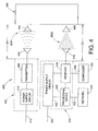
FIGURE 4 is a schematic representation of another distance indicating system which is not part of the claimed invention. -
FIGURE 5 is a schematic representation of a transceiver which is also not part of the claimed invention. -
FIGURE 6 is a schematic representation of an exemplary embodiment of a transceiver in accordance with the present novel concept. - Turning now to the drawings wherein the showings are for the purpose of illustrating exemplary embodiments of the present novel concept and not for limiting the same,
FIGURE 1 illustrates avehicle 100 having a sprung mass, such as avehicle body 102, for example, and an unsprung mass, such asaxles 104 andwheels 106, for example. A plurality of damping members, such as shock absorbers 108, for example, are secured between the sprung and unsprung masses of the vehicle in a suitable manner. Additionally, a plurality of fluid spring members, such asair spring assemblies 110, for example, are disposed between the sprung and unsprung masses of the vehicleadjacent wheels 106 andshock absorbers 108. -
Vehicle 100 also includes afluid supply system 112 that is in communication withair spring assemblies 110 and is operative to selectively supply and exhaust pressurized fluid therefrom.Fluid supply system 112 includes a pressurized fluid source, such as acompressor 114, and can optionally include a storage vessel, such asreservoir 116, for example, for receiving and storing pressurized fluid from the pressurized fluid source.System 112 can further include a suitable fluid exhaust, such as amuffler 118, for example, for venting pressurized fluid from the system. -
Fluid supply system 112 can be in communication with the fluid spring members in any suitable manner. For example,system 112 can include avalve assembly 120 or other suitable device or arrangement for selectively distributing pressurized fluid between the pressurized fluid source or sources and the fluid spring members. As shown in the exemplary embodiment inFIGURE 1 ,compressor 114,reservoir 116 andmuffler 118 are in fluid communication withvalve assembly 120. Additionally,air spring assemblies 110 are in fluid communication withvalve assembly 120 viafluid lines 122. Thus,valve assembly 120 can be selectively actuated to transfer pressurized fluid from the compressor and/or reservoir to one or more of the air spring assemblies. Additionally,valve assembly 120 can be selectively actuated to exhaust pressurized fluid from one or more of the air spring assemblies by way ofmuffler 118 or another suitable arrangement. It will be appreciated that the foregoing fluid supply system and operation thereof are merely exemplary and that any other suitable fluid source, system and/or method of operation can alternately be used. -
Vehicle 100 also includes asuspension control system 124 for selectively operating one or more suspension system components, such asshock absorbers 108,air spring assemblies 110 and/or pressurizedfluid supply system 112, for example.Suspension control system 124 includes anelectronic control unit 126 in communication with one or more components ofvalve assembly 120, such as through acommunication line 128, for example, for selective actuation and/or operation thereof. Additionally,electronic control unit 126 is in communication withair spring assemblies 110 in a suitable manner, such as throughcommunication lines 130, for example. - Suspension control systems, such as
control system 124, for example, are operable in a wide variety of manners. For example, suspension control systems, such ascontrol system 124, for example, can be used for height adjustment (i.e., to selectively raise or lower the sprung mass of a vehicle). As another example, suspension control systems, such ascontrol system 124, for example, can be used for leveling operations (i.e., to maintain the sprung mass of a vehicle in a substantially level orientation). Given this common association with height monitoring and adjustment, suspension control systems typically utilize one or more height or distance sensors to monitor the vehicle height and/or orientation. A wide variety of height sensors and/or distance determining devices are known and commonly used, as discussed in one of the foregoing sections hereof. As an alternative arrangement,air spring assemblies 110 include distance indicating systems in accordance with the present novel concept that transmitelectromagnetic waves - One exemplary embodiment of a fluid suspension member in accordance with the present novel concept is shown in
FIGURE 2 asair spring assembly 200 that includes a first orupper end member 202, a second orlower end member 204 and aflexible spring wall 206 secured therebetween. First orupper end member 202 is shown disposed along an associated upper vehicle component UVC and second orlower end member 204 is shown disposed along an associated lower vehicle component LVC. The upper and lower vehicle components could, for example, be parts of or associated with the respective sprung and unsprung masses of the vehicle. Additionally, it will be appreciated that the first and second end members can be respectively secured on the upper and lower vehicle components in any suitable manner, such as by using fasteners (not shown), for example. Furthermore, it will be appreciated thatair spring assembly 200 is shown inFIGURE 2 of a rolling-lobe construction. It is to be understood, however, that this construction is merely exemplary and that any other suitable construction can alternately be used. -
Flexible spring wall 206 at least partially defines aspring chamber 208 extending betweenend members fluid lines 122 inFIGURE 1 , for example, is in communication withspring chamber 208 through an opening formed through one of the end members of the air spring assembly, such aspassage 210 formed throughfirst end member 202, for example. A suitable connector or fitting 212 can be used to maintain fluid line FLN in operative association withspring chamber 208 throughpassage 210. -
Air spring assembly 200 also includes a distance indicating system (not numbered) that includes afirst transceiver 214 and asecond transceiver 216 spaced a distance D1 from the first transceiver.First transceiver 214 can be in communication with one or more devices or components through aconductive lead 218. For example,conductive lead 218 can be representative ofcommunication line 130 inFIGURE 1 extending between anair spring assembly 110 andelectronic control unit 126. Additionally, electrical power can be supplied from an external power source (not shown), such as a battery or vehicle alternator, for example. As shown inFIGURE 2 , however,second transceiver 216 is preferably wireless. Thus, communication to and fromsecond transceiver 216 occurs using a first electromagnetic wave EW1 and a second electromagnetic wave EW2. - In the exemplary embodiment shown in
FIGURE 2 ,first transceiver 214 is supported onfirst end member 202 andsecond transceiver 216 is supported onsecond end member 204. The first and second transceivers can be secured on the end members in any suitable manner, such as by using suitable fasteners, adhesives, bracketry or by manufacturing (e.g., molding) a transceiver or component thereof into or onto the end member. Additionally, it is to be understood that such an arrangement is merely exemplary and that any components of a distance indicating system in accordance with the present novel concept can be mounting in other positions, orientations and/or arrangements. - It will be recognized from
FIGURE 2 that the first and second transceivers can be used in a non-aligned orientation. That is, in the exemplary embodiment shown inFIGURE 2 ,second transceiver 216 is disposed approximately centrally on the second end member whereasfirst transceiver 214 is disposed outwardly toward a peripheral edge of the first end member. As such,first transceiver 214 could optionally include asecond portion 214A that is separately mountable from the first portion and in communication with one or more other devices or components through aconductive lead 218A. In such an arrangement, the first portion could be a transmitting portion and the second portion could be a receiving portion. However, any other suitable configuration, arrangement or method of operation could alternately be used. - Furthermore, it will be appreciated that distance D2 between
first transceiver 214 andfirst end member 202 and distance D3 betweensecond transceiver 216 andsecond end member 204 will normally be fixed distances. As such, one of skill in the art will recognize that the distance between the transceivers, which is represented by dimension D1 inFIGURE 2 , can also be representative of the height ofair spring assembly 200, as indicated by dimension D4, and that other dimensions or distances could be similarly determined. - One exemplary embodiment of a
distance indicating system 300 is schematically illustrated inFIGURE 3 and includes afirst transceiver 302 and asecond transceiver 304 spaced a distance D1 fromfirst transceiver 302.First transceiver 302 is in communication with a suitable external power source, such as a battery or an alternator of a vehicle, for example, through aconductive lead 306. Additionally,first transceiver 302 can be in communication with one or more other systems and/orcomponents 308, such as through a suitableconductive lead 310, for example. -
First transceiver 302 includes atransmitter 312 and afirst antenna 314 in communication with the transmitter. Suitably conditioned electrical power can be provided totransmitter 312 from an external power source (not shown) throughlead 306. Alternately,first transceiver 302 can include apower supply circuit 316 in communication withconductive lead 306 for receiving electrical energy from a suitable electrical power source.Circuit 316 can output conditioned electrical power of appropriate voltages and/or current levels for use and operation of other components oftransceiver 302. For example,power supply circuit 316 is shown inFIGURE 3 in electrical communication withtransmitter 312 and provides conditioned electrical power thereto. -
Transmitter 312 is operative to output a carrier wave signal that is broadcast as a first electromagnetic wave EW1 usingfirst antenna 314.Transceiver 302 also includes areceiver 318 in electrical communication withpower supply circuit 316 and asecond antenna 320 in electrical communication withreceiver 318.Second transceiver 304 includes afirst antenna 322 operative to receive first electromagnetic wave EW1. The second transceiver also includes asecond antenna 324 operative to transmit a second electromagnetic wave EW2, which is received atsecond antenna 320 offirst transceiver 302 and communicated toreceiver 318 thereof.Second transceiver 304 can generate a modulation signal corresponding to an input acting on an associated component of the distance indicating system, such as a structural component upon which the second transceiver is supported, for example, and utilize the modulation signal to modulate a characteristic, such as frequency or amplitude, for example, of second electromagnetic wave EW2. The receiver is operative to recover a modulating signal from the second electromagnetic wave and generate an output signal related thereto to other devices and/or systems in a suitable manner, such as to component ordevice 308 throughconductive lead 310, for example. - Optionally,
first transceiver 302 can include aprocessing device 326 in communicationwithpower supply circuit 316 that receives conditioned electrical power therefrom. Additionally,processing device 326 is in electrical communication withreceiver 318 and can receive the output signal generated thereby. The processing device can then decode or translate the output signal into data and/or other information, such as data related to a distance, acceleration value, temperature level, pressure level or other input, for example. The data and/or other information can be communicated to other devices or systems, such as a system orvehicle network 328 through aconductive lead 330, for example. - In operation, first electromagnetic wave EW1 is transmitted from
first transceiver 302 usingfirst antenna 314 and is received byfirst antenna 322 ofsecond transceiver 304. In one exemplary embodiment,first antenna 322 ofsecond transceiver 304 includes an inductive element (not shown) or other suitable feature or component, and first electromagnetic wave EW1 induces an electrical output across or along this inductive element to provide electrical power tosecond transceiver 304. Alternately, a separate electrical power source could be provided onsecond transceiver 304 to provide electrical power thereto, rather than utilizing inductive coupling withfirst transceiver 302. - Those of skill in the art will recognize that one or more properties of electromagnetic waves vary with the distance of travel of the electromagnetic wave, according to well-known relationships. Thus, by using a suitable calculation, device or comparison, the distance of travel of first electromagnetic wave EW1 (i.e., the distance D1 between the first and second transceivers) can be determined by the second transceiver and communicated to the first transceiver or another component. Alternately, a signal corresponding to the distance of travel of first electromagnetic wave EW1 and/or other data or information can be communicated from the second transceiver to a suitable device or component for receiving wave EW1 and determining the distance and/or other data or information therefrom, such suitable components can include
receiver 318 and/orprocessing device 326 of the first transceiver, for example. - Another exemplary embodiment of a
distance indicating system 400 is shown inFIGURE 4 and includes a transmittingportion 402, a receivingportion 404, and atransceiver 406. Transmittingportion 402 includes atransmitter 408 and anantenna 410 in communication with the transmitter, which is operative to generate a carrier wave signal that is broadcast as a first electromagnetic waveEW1 using antenna 410.Transmitter 408 can receive conditioned electrical power from an external power source through a suitable conductive lead, such aslead 412, for example. Alternately, transmittingportion 402 can include apower supply circuit 414 that can receive electrical power from an external power source and output conditioned electrical power totransmitter 408. - Receiving
portion 404 includes areceiver 416 and anantenna 418 in electrical communication withreceiver 416. Conditioned electrical power can be provided from an external electrical power source through a conductive lead, such aslead 420, for example. Alternately, apower supply circuit 422 can be included on receivingportion 404 that can receive electrical power from an external power source and output conditioned electrical power to the receiver.Receiver 416 is shown inFIGURE 4 as being in electrical communication with a component or device 424 through aconductive lead 426, and is operative to output communication signals thereto. Optionally, aprocessing device 428 can be included on receivingportion 404 that is in electrical communication withpower supply circuit 422 andreceiver 416.Processing device 428, if provided, can be operative to output data, signals and/or other information to other components or systems, such as a vehicle orsystem network 430, for example, through a suitable connecting device, such asconductive lead 432, for example. -
Transceiver 406 is shown inFIGURE 4 as being spaced a distance D1 from transmittingportion 402. As such, first electromagnetic wave EW1 travels across distance D1 and is received along afirst antenna 434 oftransceiver 406.Transceiver 406 is operative to output a second electromagnetic wave EW2 from asecond antenna 436 that is modulated to communicate signals, data and/or other information to receivingportion 404, in a manner similar to that discussed above with regard to distance indicatingsystem 300.System 400 differs fromdistance indicating system 300, however, in that receivingportion 404 can be positioned and secured separately from transmittingportion 402. As such, receivingportion 404 is shown a being spaced a distance D5 fromtransceiver 406, which is shown as being of a greater magnitude than distance D1. It will be appreciated, however, that distance D5 is merely representative of a distance that can be different from distance D1, and that a greater or lesser distance than that of distance D1 can be represented thereby. - One exemplary embodiment of a transceiver, such as
transceivers FIGURES 2-4 , is shown inFIGURE 5 astransceiver 500, which includes afirst antenna 502 and asecond antenna 504.First antenna 502 is operative to receive first electromagnetic wave EW1, and can include an inductive element (not shown) or other suitable device or component. First electromagnetic wave EW1 induces an electrical output across or along this inductive element to provide electrical power to the transceiver.Transceiver 500 also includes apower circuit 506 in electrical communication withfirst antenna 502.Power circuit 506 can operate to collect electrical energy induced on or alongantenna 502 by first electromagnetic wave EW1. Alternately, a separate power source, such as a battery (not shown), for example, could be used. - A
processing device 508 is in electrical communication withantenna 502 andpower circuit 506 throughelectrical conductors Power circuit 506 outputs electrical energy to the processing device that is suitably condition for the operation thereof. Additionally, an electrical signal output fromantenna 502 is communicated toprocessing device 508 alongelectrical conductor 510, and the processing device is operative to output a modulation signal to atransmitter 514 along anelectrical conductor 516. In one exemplary embodiment, the modulation signal output by the processing device has a relationship to the distance between the device or component that is broadcasting the first electromagnetic wave (e.g.,transceiver 302 or transmitter portion 402) andtransceiver 500.Power circuit 506 is also in communication withtransmitter 514 throughelectrical conductor 518 and supplies electrical power thereto.Transmitter 514 is operative to generate a carrier wave signal and combine the carrier wave signal with the modulation signal from processingdevice 508 to transmit second electromagnetic wave EW2 usingsecond antenna 504. - According to one exemplary embodiment,
processing device 508 can be operative to translate or convert an electrical signal fromantenna 502 into an amplitude and/or frequency varied modulation signal in which the variations in amplitude and/or frequency correspond to the voltage or current level of the electrical signal from the antenna. Again, it will be recognized that the voltage and/or current level of the electrical signal from the antenna will vary with the distance of travel of the first electromagnetic wave, which corresponds to the distance between the transceivers or other components. Thus, a distance measurement can be communicated as variations in frequency and/or amplitude of an electromagnetic wave. Therefore, electromagnetic wave EW2 is modulated in relation to the distance between the first and second transceivers. The modulated electromagnetic wave can be received by a receiving device or component, such asfirst transceiver 302 orreceiver portion 404, for example, which can recover the modulation signal and output the same to a different component or system, which can determine the distance based thereon. Alternately, the receiving device or component can convert the modulation signal or otherwise determine the distance based on the modulation of the second electromagnetic wave EW2 and output data and/or information corresponding to the distance. - One example of a suitable component for use as
processing device 508 is a voltage controlled oscillator or voltage-to-frequency converter that is operative to provide a variable frequency output in response to variations in input voltage. One example of a suitable voltage-to-frequency converter is available from National Semiconductor Corp. of Santa Clara, California under the product designation LM231AN. - Another exemplary embodiment of a transceiver, such as
transceivers FIGURES 2-5 , is shown inFIGURE 6 astransceiver 600, which includes afirst antenna 602 and asecond antenna 604.Transceiver 600 also includes apower circuit 606 in electrical communication withantenna 602 and is operable to collect electrical energy induced on or along the first antenna as discussed above in detail. Aprocessing device 608 is in electrical communication withpower circuit 606 through anelectrical conductor 610 and receives electrical energy therefrom that is suitably conditioned for operation of the processing device. Afirst sensor 612 is in electrical communication betweenantenna 602 andprocessing device 608 throughelectrical conductors sensor 612 is operative to output a signal related to the distance of travel of first electromagnetic wave EW1, as discussed above, and to communicate the sensor output signal toprocessing device 608. - Similar to
processing device 508 intransceiver 500,first sensor 612 can be operative to vary the frequency and/or amplitude of the output signal thereof in response to variations in the voltage and/or current fromantenna 602 alongconductor 614. Alternately, an analog-to-digital converter or other suitable device can be used assensor 612 to receive the input from alongconductor 614 and transmit a digitized output signal toprocessing device 608 alongconductor 616. As such,processing device 608 includes a device, such as a programmable microprocessor, microcontroller or microcomputer, for example, that is capable of receiving the digitized sensor input signal and generating a modulation signal corresponding to the distance of travel of the first electromagnetic wave. - The processing device, outputs the modulation signal to
transmitter 618 through anelectrical conductor 620.Transmitter 618 is in electrical communication withpower circuit 606 throughelectrical conductor 622. The transmitter generates a second carrier wave signal and combines the same with the modulation signal to create modulated second electromagnetic wave EW2 that is transmitted bysecond antenna 604. - In one exemplary embodiment,
transceiver 600 can also include one or more additional components, such assensors FIGURE 6 ,sensor 624 is in electrical communication betweenpower circuit 606 andprocessing device 608 throughconductive elements sensor 626 is in electrical communication between the power circuit and the processing device throughconductive elements - If additional components, such as
sensors 624 and/or 626, for example, are provided,processing device 608 will preferably be operative to receive output signals from these components as well as fromsensor 612. The processing device can then communicate the signals or data and/or information corresponding thereto to the receiving device or component. One example of suitable operation includesprocessing device 608 combining or encoding the various output signals and generating a modulation signal suitable for communicating the data and/or information from the sensors or other components. Optionally, signal encoding schemes can be used, such a frequency-shift keying, phase-shift keying, for example.Transmitter 618 then modulates the carrier wave using the modulation signal and the data and/or information is communicated to the first transceiver using second electromagnetic wave EW2, as discussed above. The first transceiver or receiving portion can thereafter recover and decode the modulation signal to output signals, data and/or information related to the output from the one or more sensors. - First electromagnetic wave EW1 and second electromagnetic wave EW2 are respectively based upon first and second unmodulated carrier wave signals. The unmodulated carrier wave signals can be generated in any suitable manner and in one exemplary embodiment are generated by a corresponding transmitter. For example, the first carrier wave signal can be generated by
transmitter transmitter
Claims (6)
- An air spring assembly (110) including:a first end member (202);a second end member (204) spaced from said first end member (202);a flexible spring wall (206) supported between said first and second end members (202, 206) and at least partially forming a fluid chamber therebetween;a first transceiver (214; 302; 402) supported on said first end member (202), said first transceiver operative to transmit a first electromagnetic wave (EW1) and operative to receive a second electromagnetic wave (EW2); anda second transceiver (600) supported on said second end member (204) at a distance (D1) from said first transceiver (214; 302; 402), said second transceiver (600) operative to receive by means of a first antenna (322; 434; 502; 602) said first electromagnetic wave (EW1) and transmit by means of a second antenna (324; 436; 504; 604) said second electromagnetic wave (EW2),said second transceiver (600) including a processing device (608) operative to receive an electrical signal from the first antenna (322,; 434; 502; 602) having an induced voltage or current level in relation to said distance (D1),characterized in that
said second transceiver (600) includes a sensor (624, 626) in electrical communication with said processing device (608), said sensor (624, 626) being operative to output a sensor signal to said processing device (608) indicative of an input acting on one of said second transceiver (600) and said second end member (204),
whereby said second electromagnetic wave (EW2) is modulated in said second transceiver (600) in relation to said second electrical signal from the first antenna (322; 434; 502; 602) and the sensor signal from said sensor (624, 626). - An air spring assembly (110) according to claim 1,
wherein said first transceiver (214; 302; 402) includes a receiver (318; 416) in electrical communication with an antenna (320; 418) thereof and operative to generate an output signal having a relation to said distance (D1) and a processing device (326; 428) receiving said output signal and determining said distance (D1) based on said output signal. - An air spring assembly (110) according to claim 1 or claim 2,
wherein said second transceiver (600) is inductively coupled to said first transceiver (214; 302; 402), and said second transceiver (600) includes a power circuit (606) operative to collect electrical energy due to said inductive coupling with said first transceiver (214; 302; 402). - An air spring assembly (110) according to any one of claims 1-3,
wherein said sensor (624, 626) is one of an accelerometer, a thermocouple and a pressure transducer. - A method of determining a distance between first and second end members (202, 204) of an air spring (110), said method including:a) providing a first transceiver (214; 302; 402) supported adjacent the first end member (202) and comprising a transmitter (312; 408) broadcasting a first electromagnetic wave (EW1);b) providing a second transceiver (600) supported in spaced relation to said first transceiver (214; 302; 402) adjacent said second end member (204) and operative to receive by means of an antenna (322; 434; 502; 602) said first electromagnetic wave (EW1) and transmitting a modulated second electromagnetic wave (EW2);c) inducing an electrical signal in said second transceiver (600) using said first electromagnetic wave (EW1);d) including a sensor (624, 626) outputting a sensor signal related to an input acting on one of said second transceiver (600) and said second end member (204);e) transmitting said second electromagnetic wave (EW2) which has been modulated by said induced electrical signal having a voltage or a current level in relation to a distance (D1) between said first transceiver (214; 302; 402) and said second transceiver (600), and by said sensor signal from said sensor (624, 626); andf) determining in said first transceiver (214; 302; 402) said distance (D1) between said first transceiver (214; 302; 402) and said second transceiver (600) based on said modulated second electromagnetic wave (EW2).
- A method according to claim 5,
wherein e) includes modulating said second electromagnetic wave (EW2) using one of amplitude modulation and frequency modulation to generate said modulated second electromagnetic wave (EW2).
Applications Claiming Priority (2)
| Application Number | Priority Date | Filing Date | Title |
|---|---|---|---|
| US11/337,746 US7420462B2 (en) | 2006-01-23 | 2006-01-23 | Air spring distance indicating system and method |
| PCT/US2007/001532 WO2007087235A1 (en) | 2006-01-23 | 2007-01-19 | Distance indicating system and method |
Publications (2)
| Publication Number | Publication Date |
|---|---|
| EP1991432A1 EP1991432A1 (en) | 2008-11-19 |
| EP1991432B1 true EP1991432B1 (en) | 2015-04-22 |
Family
ID=37964636
Family Applications (1)
| Application Number | Title | Priority Date | Filing Date |
|---|---|---|---|
| EP07716847.4A Active EP1991432B1 (en) | 2006-01-23 | 2007-01-19 | Distance indicating system and method |
Country Status (8)
| Country | Link |
|---|---|
| US (2) | US7420462B2 (en) |
| EP (1) | EP1991432B1 (en) |
| JP (1) | JP2009524062A (en) |
| CN (1) | CN101405156B (en) |
| AU (1) | AU2007208409B2 (en) |
| HK (1) | HK1128261A1 (en) |
| RU (1) | RU2407655C2 (en) |
| WO (1) | WO2007087235A1 (en) |
Families Citing this family (31)
| Publication number | Priority date | Publication date | Assignee | Title |
|---|---|---|---|---|
| GB2406548A (en) * | 2003-10-03 | 2005-04-06 | Trelleborg Ab | Air suspension system |
| US7643796B2 (en) * | 2006-04-12 | 2010-01-05 | Honeywell International Inc. | System and method for process control using wireless devices with multiple transceivers and at least one process element |
| US7894473B2 (en) * | 2006-04-12 | 2011-02-22 | Honeywell International Inc. | System and method for monitoring valve status and performance in a process control system |
| US7733239B2 (en) * | 2006-05-08 | 2010-06-08 | Bfs Diversified Products, Llc | Distance determining system and method |
| US8160774B2 (en) * | 2008-10-15 | 2012-04-17 | GM Global Technology Operations LLC | Vehicular actuator system |
| US8174377B2 (en) * | 2008-11-14 | 2012-05-08 | GM Global Technology Operations LLC | Suspension height sensor |
| US8175770B2 (en) * | 2008-11-17 | 2012-05-08 | GM Global Technology Operations LLC | Height sensing system for a vehicular suspension assembly |
| US9191263B2 (en) * | 2008-12-23 | 2015-11-17 | Keyssa, Inc. | Contactless replacement for cabled standards-based interfaces |
| US9219956B2 (en) | 2008-12-23 | 2015-12-22 | Keyssa, Inc. | Contactless audio adapter, and methods |
| SE533463C2 (en) * | 2009-02-26 | 2010-10-05 | Stroemsholmen Ab | Balancing device for balancing two relatively moving parts including a gas spring and method for balancing |
| US8063498B2 (en) * | 2009-02-27 | 2011-11-22 | GM Global Technology Operations LLC | Harvesting energy from vehicular vibrations |
| US7936113B2 (en) * | 2009-02-27 | 2011-05-03 | GM Global Technology Operations LLC | Harvesting energy from vehicular vibrations using piezoelectric devices |
| US8143766B2 (en) * | 2009-02-27 | 2012-03-27 | GM Global Technology Operations LLC | Harvesting energy from vehicular vibrations using piezoelectric devices |
| US8253281B2 (en) * | 2009-02-27 | 2012-08-28 | GM Global Technology Operations LLC | Energy harvesting apparatus incorporated into shock absorber |
| US7956797B2 (en) * | 2009-03-09 | 2011-06-07 | GM Global Technology Operations LLC | System and method for measuring a relative distance between vehicle components using ultra-wideband techniques |
| CN101905694B (en) * | 2009-06-04 | 2012-12-26 | 品秀橡胶股份有限公司 | Intelligent electronic suspension system capable of adjusting air pressure automatically |
| US8614518B2 (en) * | 2009-10-14 | 2013-12-24 | GM Global Technology Operations LLC | Self-powered vehicle sensor systems |
| US8905071B2 (en) | 2010-10-26 | 2014-12-09 | Air Lift Company | Integrated manifold system for controlling an air suspension |
| DE102012213697A1 (en) * | 2012-08-02 | 2014-02-06 | Robert Bosch Gmbh | Sensor device and method for determining a pressure of a medium located within an electrochemical energy store, electrochemical energy store and method for producing the same |
| DE102013215360B4 (en) * | 2012-09-10 | 2015-09-10 | Ford Global Technologies, Llc | Height adjustment device for vehicles with air spring and vibration damper |
| EP2724877B1 (en) | 2012-10-29 | 2019-03-20 | ContiTech USA, Inc. | Air spring with a sensor arrangement |
| EP2728217B1 (en) * | 2012-11-02 | 2019-08-21 | ContiTech USA, Inc. | Air spring height measurement arrangement |
| JP6345450B2 (en) * | 2014-03-14 | 2018-06-20 | 住友電気工業株式会社 | Air spring |
| DE102015002167A1 (en) * | 2015-02-24 | 2016-08-25 | Wabco Gmbh | Method and system for altitude measurement in a vehicle |
| DE102016218603A1 (en) * | 2016-09-27 | 2018-03-29 | Jost-Werke Deutschland Gmbh | Device for detecting the position of a first or second vehicle to be coupled together |
| MX2019015275A (en) | 2017-06-16 | 2020-07-20 | Base Air Man Limited | Symmetrically dynamic equalized volume and pressure air management system. |
| US10220665B2 (en) | 2017-06-16 | 2019-03-05 | BASE Air Management, Inc. | Symmetrically dynamic equalized volume and pressure air management system |
| TWI775965B (en) | 2017-10-17 | 2022-09-01 | 澳洲商巴斯空氣管理有限公司 | Symmetrically dynamic equalized volume and pressure air management system |
| MX2020003625A (en) * | 2017-10-19 | 2020-12-10 | Saf Holland Inc | Dynamic heavy-duty vehicle suspension arrangement. |
| EP3849831A1 (en) * | 2018-09-13 | 2021-07-21 | Firestone Industrial Products Company, LLC | Communication modules as well as gas spring assemblies and vehicle systems including same |
| DE102021214579A1 (en) * | 2021-12-17 | 2023-06-22 | Contitech Ag | air spring arrangement |
Citations (1)
| Publication number | Priority date | Publication date | Assignee | Title |
|---|---|---|---|---|
| WO2006115747A2 (en) * | 2005-04-27 | 2006-11-02 | Bfs Diversified Products, Llc | Sensing and communication system and method |
Family Cites Families (78)
| Publication number | Priority date | Publication date | Assignee | Title |
|---|---|---|---|---|
| US3780370A (en) * | 1971-03-11 | 1973-12-18 | Brown & Root | Electronic range measuring method and apparatus |
| US3859624A (en) * | 1972-09-05 | 1975-01-07 | Thomas A Kriofsky | Inductively coupled transmitter-responder arrangement |
| JPS5916229B2 (en) * | 1972-09-26 | 1984-04-13 | クリスチアン ハイゲン ラボラトリウム ビ− ブイ | Data transfer method and device between two stations |
| GB1511354A (en) * | 1975-05-07 | 1978-05-17 | Nat Res Dev | Distance measuring apparatus |
| US4183022A (en) * | 1976-06-03 | 1980-01-08 | Electronique Marcel Dassault | Transponder for radiocommunication system, particularly for measuring the distance between two stations |
| US4041490A (en) | 1976-06-25 | 1977-08-09 | Cubic Corporation | Measurement system calibrated to be insensitive to temperature variation induced changes in internal phase shifts present in the system |
| US4307397A (en) * | 1977-12-05 | 1981-12-22 | The South African Inventions Development Corporation | Method of and apparatus for measuring distance |
| US4278977A (en) * | 1979-05-04 | 1981-07-14 | Rca Corporation | Range determining system |
| US4646092A (en) * | 1982-06-07 | 1987-02-24 | Plessey South Africa Limited | Method of and apparatus for continuous wave electromagnetic distance measurement of positioning |
| JPS60121130A (en) * | 1983-12-06 | 1985-06-28 | Nissan Motor Co Ltd | Vehicle travel control device |
| DE3423602A1 (en) | 1984-06-27 | 1986-01-09 | Robert Bosch Gmbh, 7000 Stuttgart | Device for measuring the distance between the chassis and the axle of a vehicle |
| FR2574188B1 (en) | 1984-11-30 | 1987-02-27 | Inst Selskokhozyaistvennogo | METHOD FOR MEASURING THE DISTANCE UP TO A CONTROLLED TOOL CARRIER TRACTOR AND DEVICE FOR CARRYING OUT SAID METHOD |
| GB8516765D0 (en) | 1985-07-02 | 1985-08-07 | Dunlop Ltd | Suspension systems |
| SE456118B (en) * | 1985-12-12 | 1988-09-05 | Stiftelsen Inst Mikrovags | PROCEDURE AND DEVICE FOR MEASURING DISTANCE BETWEEN A SUBSTANCE AND ANOTHER FORM WITH SIGNALS OF MICROWAVE FREQUENCY |
| US4757315A (en) * | 1986-02-20 | 1988-07-12 | The United States Of America As Represented By The Administrator Of The National Aeronautics And Space Administration | Method and apparatus for measuring distance |
| DE3614744C2 (en) * | 1986-04-30 | 1994-11-10 | Koenig & Bauer Ag | Device for controlling a rotary printing machine |
| US4739328A (en) | 1986-07-14 | 1988-04-19 | Amtech Corporation | System for identifying particular objects |
| US4737705A (en) * | 1986-11-05 | 1988-04-12 | Caterpillar Inc. | Linear position sensor using a coaxial resonant cavity |
| US4817922A (en) * | 1987-10-23 | 1989-04-04 | The Goodyear Tire & Rubber Company | Airspring height sensor |
| US4798369A (en) * | 1987-11-03 | 1989-01-17 | The Firestone Tire & Rubber Company | Ultrasonic air spring system |
| US5701121A (en) * | 1988-04-11 | 1997-12-23 | Uniscan Ltd. | Transducer and interrogator device |
| US4939328A (en) * | 1988-12-23 | 1990-07-03 | Judco Manufacturing, Incorporated | Quiet switching apparatus and method of operation |
| US5285189A (en) * | 1991-05-14 | 1994-02-08 | Epic Technologies, Inc. | Abnormal tire condition warning system |
| US5266926A (en) * | 1991-05-31 | 1993-11-30 | Avid Marketing, Inc. | Signal transmission and tag power consumption measurement circuit for an inductive reader |
| US6738697B2 (en) * | 1995-06-07 | 2004-05-18 | Automotive Technologies International Inc. | Telematics system for vehicle diagnostics |
| JP3069408B2 (en) * | 1991-08-09 | 2000-07-24 | 株式会社ブリヂストン | Height sensor and air spring |
| JP3187496B2 (en) * | 1992-01-09 | 2001-07-11 | スタンレー電気株式会社 | Height sensor and air spring |
| JP3599336B2 (en) * | 1992-02-18 | 2004-12-08 | シチズン時計株式会社 | Data carrier systems and antennas in fixed facilities |
| US5373445A (en) * | 1992-03-05 | 1994-12-13 | Ford Motor Company | Method and apparatus for determining dynamic force within an air spring suspension |
| US5298904A (en) * | 1992-08-04 | 1994-03-29 | Olich Kirk J | Distance measuring system |
| US5450088A (en) * | 1992-11-25 | 1995-09-12 | Texas Instruments Deutschland Gmbh | Transponder arrangement |
| EP0650074A1 (en) * | 1993-10-22 | 1995-04-26 | Texas Instruments Holland B.V. | Highly accurate RF-ID positioning system |
| JPH07181254A (en) | 1993-12-22 | 1995-07-21 | Hitachi Constr Mach Co Ltd | Safety system of construction machine |
| US5552789A (en) * | 1994-02-14 | 1996-09-03 | Texas Instruments Deutschland Gmbh | Integrated vehicle communications system |
| DE4413341C2 (en) * | 1994-04-18 | 1999-08-26 | Continental Ag | Measuring device with a magnetic field sensor for contactless detection of the clear distance between two components and their use |
| US5731754A (en) * | 1994-06-03 | 1998-03-24 | Computer Methods Corporation | Transponder and sensor apparatus for sensing and transmitting vehicle tire parameter data |
| US5500065A (en) * | 1994-06-03 | 1996-03-19 | Bridgestone/Firestone, Inc. | Method for embedding a monitoring device within a tire during manufacture |
| US5550536A (en) * | 1994-08-17 | 1996-08-27 | Texas Instruments Deutschland Gmbh | Circuit frequency following technique transponder resonant |
| JPH0962816A (en) * | 1994-10-06 | 1997-03-07 | Mitsubishi Electric Corp | Non-contact ic card and non-contact ic card system including the same |
| US5589821A (en) * | 1994-12-13 | 1996-12-31 | Secure Technologies, Inc. | Distance determination and alarm system |
| US5707045A (en) * | 1996-09-05 | 1998-01-13 | Bridgestone/Firestone, Inc. | Air spring system having an integral height sensor |
| DE19648112C1 (en) * | 1996-11-21 | 1998-03-05 | Contitech Luftfedersyst Gmbh | Device for contactless distance measurement |
| DE19701530C1 (en) | 1997-01-17 | 1998-08-06 | Contitech Luftfedersyst Gmbh | Axial distance determination between end members of compressed gas spring for vehicle |
| US5859692A (en) * | 1997-05-16 | 1999-01-12 | Rochester Gauges, Inc. | Height sensor and air spring apparatus incorporating the same in the air chamber |
| US6036179A (en) | 1997-12-22 | 2000-03-14 | Bridgestone/Firestone, Inc. | Air spring containing an active device and a suspension assembly and method using |
| US6122329A (en) | 1998-02-06 | 2000-09-19 | Intermec Ip Corp. | Radio frequency identification interrogator signal processing system for reading moving transponders |
| DE19820877C2 (en) * | 1998-05-09 | 2002-09-19 | Contitech Luftfedersyst Gmbh | Non-contact distance and pressure measurement within an air spring |
| US6111536A (en) | 1998-05-26 | 2000-08-29 | Time Domain Corporation | System and method for distance measurement by inphase and quadrature signals in a radio system |
| JP3916328B2 (en) * | 1998-07-27 | 2007-05-16 | ローム株式会社 | Contactless communication system |
| US6249673B1 (en) * | 1998-11-09 | 2001-06-19 | Philip Y. W. Tsui | Universal transmitter |
| US6309494B1 (en) | 1998-12-04 | 2001-10-30 | Bridgestone/Firestone Research, Inc. | Method of attaching sensitive electronic equipment to the inner surface of a tire |
| US6356738B1 (en) * | 1999-02-18 | 2002-03-12 | Gary W. Schneider | Method and apparatus for communicating data with a transponder |
| FR2792134B1 (en) * | 1999-04-07 | 2001-06-22 | St Microelectronics Sa | DISTANCE DETECTION BETWEEN AN ELECTROMAGNETIC TRANSPONDER AND A TERMINAL |
| IL129651A (en) * | 1999-04-28 | 2004-08-31 | Nexense Ltd | High-precision measuring method and apparatus |
| US6474380B1 (en) | 1999-04-29 | 2002-11-05 | Bridgestone/Firestone North American Tire, Llc | Pneumatic tire and monitoring device including dipole antenna |
| US6414626B1 (en) | 1999-08-20 | 2002-07-02 | Micron Technology, Inc. | Interrogators, wireless communication systems, methods of operating an interrogator, methods of operating a wireless communication system, and methods of determining range of a remote communication device |
| WO2001084518A1 (en) | 2000-05-01 | 2001-11-08 | Isc/Us, Inc. | Data capture and logging with passive rf transmission |
| US6469590B1 (en) * | 2000-06-20 | 2002-10-22 | Shakespeare Company | Marine antenna with an integral filter |
| JP2004502177A (en) * | 2000-06-27 | 2004-01-22 | シーメンス アクチエンゲゼルシヤフト | Method for measuring the distance between two objects, and for controlling access control to an object or for controlling the use of an object, especially an access control and travel authentication device for a motor vehicle |
| WO2002029435A1 (en) | 2000-10-04 | 2002-04-11 | Siemens Aktiengesellschaft | Method and device for the wireless measurement of a movement of at least one object |
| DE10051825A1 (en) | 2000-10-19 | 2002-04-25 | Contitech Luftfedersyst Gmbh | Motor vehicle air spring system with ultrasound measuring arrangement |
| US7243852B2 (en) | 2000-11-13 | 2007-07-17 | Bridgestone Firestone North American Tire, Llc | Wheel assembly identification device |
| JP4152595B2 (en) * | 2001-01-11 | 2008-09-17 | 横浜ゴム株式会社 | Transponder and its system |
| ITTO20010035A1 (en) * | 2001-01-19 | 2002-07-19 | Comau Systems Spa | PROCEDURE AND SYSTEM FOR MEASURING THE DISTANCE OF A MOBILE BODY FROM A FIXED PART. |
| JP3461498B2 (en) * | 2001-03-01 | 2003-10-27 | 徹志 上保 | Distance measuring device, distance measuring equipment and distance measuring method |
| DE10126087A1 (en) * | 2001-05-29 | 2002-12-05 | Sick Ag | Distance determination method and device |
| MXPA03010783A (en) | 2001-06-01 | 2004-03-02 | Boler Co | Radio frequency-controlled axle/suspension lift system. |
| DE10151593A1 (en) * | 2001-10-18 | 2003-04-30 | Contitech Luftfedersyst Gmbh | Air spring interior space pressure determining method for motor vehicle, involves providing ultrasonic pulse measuring arrangement with transmitter circuit, transducer with adaption layer of fixed constant, and reflector |
| DE10155251A1 (en) * | 2001-11-09 | 2003-06-18 | Siemens Ag | Transponder system and method for distance measurement |
| US7139581B2 (en) * | 2002-05-02 | 2006-11-21 | Aeroscout, Inc. | Method and system for distance measurement in a low or zero intermediate frequency half-duplex communications loop |
| US6963301B2 (en) * | 2002-08-19 | 2005-11-08 | G-Track Corporation | System and method for near-field electromagnetic ranging |
| DE10253278B4 (en) * | 2002-11-15 | 2009-10-08 | Continental Automotive Gmbh | Tire measurement with an energy self-modulated backscatter transponder |
| DE10325396A1 (en) * | 2003-05-28 | 2004-12-23 | Atmel Germany Gmbh | Circuit arrangement for phase modulation for backscatter-based transponder has control unit that can selectively connect voltage sources to varactor connection(s) depending on desired phase angle |
| JP2005092343A (en) * | 2003-09-12 | 2005-04-07 | Amplet:Kk | Rfid system |
| JP2005112155A (en) | 2003-10-08 | 2005-04-28 | Hitachi Ltd | Suspension device |
| US7310044B2 (en) * | 2004-05-17 | 2007-12-18 | Denso Corporation | Tire condition monitoring system and method |
| US7490817B2 (en) | 2005-01-04 | 2009-02-17 | Bfs Diversified Products Llc | Distance indicating system and method |
| US20070013544A1 (en) * | 2005-07-14 | 2007-01-18 | Shin-Yung Chiu | Wireless transceiver with multiple independent modulating transmitters |
-
2006
- 2006-01-23 US US11/337,746 patent/US7420462B2/en active Active
-
2007
- 2007-01-19 AU AU2007208409A patent/AU2007208409B2/en not_active Ceased
- 2007-01-19 EP EP07716847.4A patent/EP1991432B1/en active Active
- 2007-01-19 CN CN2007800084715A patent/CN101405156B/en not_active Expired - Fee Related
- 2007-01-19 WO PCT/US2007/001532 patent/WO2007087235A1/en active Application Filing
- 2007-01-19 RU RU2008134330/11A patent/RU2407655C2/en not_active IP Right Cessation
- 2007-01-19 JP JP2008551434A patent/JP2009524062A/en active Pending
-
2008
- 2008-06-23 US US12/144,286 patent/US7532110B2/en active Active
-
2009
- 2009-07-03 HK HK09105976.8A patent/HK1128261A1/en not_active IP Right Cessation
Patent Citations (1)
| Publication number | Priority date | Publication date | Assignee | Title |
|---|---|---|---|---|
| WO2006115747A2 (en) * | 2005-04-27 | 2006-11-02 | Bfs Diversified Products, Llc | Sensing and communication system and method |
Also Published As
| Publication number | Publication date |
|---|---|
| CN101405156B (en) | 2010-09-01 |
| EP1991432A1 (en) | 2008-11-19 |
| US7420462B2 (en) | 2008-09-02 |
| AU2007208409A1 (en) | 2007-08-02 |
| HK1128261A1 (en) | 2009-10-23 |
| RU2407655C2 (en) | 2010-12-27 |
| WO2007087235A1 (en) | 2007-08-02 |
| AU2007208409B2 (en) | 2010-09-02 |
| RU2008134330A (en) | 2010-02-27 |
| US20070171036A1 (en) | 2007-07-26 |
| JP2009524062A (en) | 2009-06-25 |
| US20080246596A1 (en) | 2008-10-09 |
| CN101405156A (en) | 2009-04-08 |
| US7532110B2 (en) | 2009-05-12 |
Similar Documents
| Publication | Publication Date | Title |
|---|---|---|
| EP1991432B1 (en) | Distance indicating system and method | |
| US7733239B2 (en) | Distance determining system and method | |
| EP2735760B1 (en) | Air spring with a height sensor | |
| EP1834190B1 (en) | Distance indicating system and method | |
| EP1888358B1 (en) | Air spring assembly with localized signal processing, system and method utilizing same, as well as operating module therefor | |
| EP1878125B1 (en) | Sensing and communication system and method | |
| CA2256655C (en) | Air spring containing an active device and a suspension assembly and method using same | |
| EP0828087B1 (en) | Air spring system having an integral height sensor | |
| EP1602906A1 (en) | Reducing coupling of SAW | |
| JP5075623B2 (en) | Tire sensor system and body mounted with the same |
Legal Events
| Date | Code | Title | Description |
|---|---|---|---|
| PUAI | Public reference made under article 153(3) epc to a published international application that has entered the european phase |
Free format text: ORIGINAL CODE: 0009012 |
|
| 17P | Request for examination filed |
Effective date: 20080814 |
|
| AK | Designated contracting states |
Kind code of ref document: A1 Designated state(s): AT BE BG CH CY CZ DE DK EE ES FI FR GB GR HU IE IS IT LI LT LU LV MC NL PL PT RO SE SI SK TR |
|
| 17Q | First examination report despatched |
Effective date: 20090219 |
|
| DAX | Request for extension of the european patent (deleted) | ||
| GRAP | Despatch of communication of intention to grant a patent |
Free format text: ORIGINAL CODE: EPIDOSNIGR1 |
|
| RIC1 | Information provided on ipc code assigned before grant |
Ipc: B60G 17/019 20060101AFI20141028BHEP Ipc: G01S 13/82 20060101ALI20141028BHEP Ipc: G06K 7/08 20060101ALN20141028BHEP Ipc: B60G 17/052 20060101ALI20141028BHEP Ipc: H04B 5/00 20060101ALN20141028BHEP Ipc: F16F 9/05 20060101ALI20141028BHEP Ipc: G01S 13/75 20060101ALI20141028BHEP |
|
| INTG | Intention to grant announced |
Effective date: 20141112 |
|
| GRAS | Grant fee paid |
Free format text: ORIGINAL CODE: EPIDOSNIGR3 |
|
| GRAA | (expected) grant |
Free format text: ORIGINAL CODE: 0009210 |
|
| AK | Designated contracting states |
Kind code of ref document: B1 Designated state(s): AT BE BG CH CY CZ DE DK EE ES FI FR GB GR HU IE IS IT LI LT LU LV MC NL PL PT RO SE SI SK TR |
|
| REG | Reference to a national code |
Ref country code: GB Ref legal event code: FG4D |
|
| REG | Reference to a national code |
Ref country code: CH Ref legal event code: EP |
|
| REG | Reference to a national code |
Ref country code: AT Ref legal event code: REF Ref document number: 722985 Country of ref document: AT Kind code of ref document: T Effective date: 20150515 |
|
| REG | Reference to a national code |
Ref country code: IE Ref legal event code: FG4D |
|
| REG | Reference to a national code |
Ref country code: DE Ref legal event code: R096 Ref document number: 602007041145 Country of ref document: DE Effective date: 20150603 |
|
| REG | Reference to a national code |
Ref country code: NL Ref legal event code: VDEP Effective date: 20150422 |
|
| REG | Reference to a national code |
Ref country code: AT Ref legal event code: MK05 Ref document number: 722985 Country of ref document: AT Kind code of ref document: T Effective date: 20150422 |
|
| REG | Reference to a national code |
Ref country code: LT Ref legal event code: MG4D |
|
| PG25 | Lapsed in a contracting state [announced via postgrant information from national office to epo] |
Ref country code: NL Free format text: LAPSE BECAUSE OF FAILURE TO SUBMIT A TRANSLATION OF THE DESCRIPTION OR TO PAY THE FEE WITHIN THE PRESCRIBED TIME-LIMIT Effective date: 20150422 |
|
| PG25 | Lapsed in a contracting state [announced via postgrant information from national office to epo] |
Ref country code: PT Free format text: LAPSE BECAUSE OF FAILURE TO SUBMIT A TRANSLATION OF THE DESCRIPTION OR TO PAY THE FEE WITHIN THE PRESCRIBED TIME-LIMIT Effective date: 20150824 Ref country code: FI Free format text: LAPSE BECAUSE OF FAILURE TO SUBMIT A TRANSLATION OF THE DESCRIPTION OR TO PAY THE FEE WITHIN THE PRESCRIBED TIME-LIMIT Effective date: 20150422 Ref country code: LT Free format text: LAPSE BECAUSE OF FAILURE TO SUBMIT A TRANSLATION OF THE DESCRIPTION OR TO PAY THE FEE WITHIN THE PRESCRIBED TIME-LIMIT Effective date: 20150422 Ref country code: ES Free format text: LAPSE BECAUSE OF FAILURE TO SUBMIT A TRANSLATION OF THE DESCRIPTION OR TO PAY THE FEE WITHIN THE PRESCRIBED TIME-LIMIT Effective date: 20150422 |
|
| PG25 | Lapsed in a contracting state [announced via postgrant information from national office to epo] |
Ref country code: AT Free format text: LAPSE BECAUSE OF FAILURE TO SUBMIT A TRANSLATION OF THE DESCRIPTION OR TO PAY THE FEE WITHIN THE PRESCRIBED TIME-LIMIT Effective date: 20150422 Ref country code: LV Free format text: LAPSE BECAUSE OF FAILURE TO SUBMIT A TRANSLATION OF THE DESCRIPTION OR TO PAY THE FEE WITHIN THE PRESCRIBED TIME-LIMIT Effective date: 20150422 Ref country code: IS Free format text: LAPSE BECAUSE OF FAILURE TO SUBMIT A TRANSLATION OF THE DESCRIPTION OR TO PAY THE FEE WITHIN THE PRESCRIBED TIME-LIMIT Effective date: 20150822 Ref country code: GR Free format text: LAPSE BECAUSE OF FAILURE TO SUBMIT A TRANSLATION OF THE DESCRIPTION OR TO PAY THE FEE WITHIN THE PRESCRIBED TIME-LIMIT Effective date: 20150723 |
|
| REG | Reference to a national code |
Ref country code: DE Ref legal event code: R097 Ref document number: 602007041145 Country of ref document: DE |
|
| PG25 | Lapsed in a contracting state [announced via postgrant information from national office to epo] |
Ref country code: EE Free format text: LAPSE BECAUSE OF FAILURE TO SUBMIT A TRANSLATION OF THE DESCRIPTION OR TO PAY THE FEE WITHIN THE PRESCRIBED TIME-LIMIT Effective date: 20150422 Ref country code: DK Free format text: LAPSE BECAUSE OF FAILURE TO SUBMIT A TRANSLATION OF THE DESCRIPTION OR TO PAY THE FEE WITHIN THE PRESCRIBED TIME-LIMIT Effective date: 20150422 |
|
| PLBE | No opposition filed within time limit |
Free format text: ORIGINAL CODE: 0009261 |
|
| STAA | Information on the status of an ep patent application or granted ep patent |
Free format text: STATUS: NO OPPOSITION FILED WITHIN TIME LIMIT |
|
| PG25 | Lapsed in a contracting state [announced via postgrant information from national office to epo] |
Ref country code: SK Free format text: LAPSE BECAUSE OF FAILURE TO SUBMIT A TRANSLATION OF THE DESCRIPTION OR TO PAY THE FEE WITHIN THE PRESCRIBED TIME-LIMIT Effective date: 20150422 Ref country code: PL Free format text: LAPSE BECAUSE OF FAILURE TO SUBMIT A TRANSLATION OF THE DESCRIPTION OR TO PAY THE FEE WITHIN THE PRESCRIBED TIME-LIMIT Effective date: 20150422 Ref country code: RO Free format text: LAPSE BECAUSE OF NON-PAYMENT OF DUE FEES Effective date: 20150422 Ref country code: CZ Free format text: LAPSE BECAUSE OF FAILURE TO SUBMIT A TRANSLATION OF THE DESCRIPTION OR TO PAY THE FEE WITHIN THE PRESCRIBED TIME-LIMIT Effective date: 20150422 |
|
| 26N | No opposition filed |
Effective date: 20160125 |
|
| PG25 | Lapsed in a contracting state [announced via postgrant information from national office to epo] |
Ref country code: IT Free format text: LAPSE BECAUSE OF FAILURE TO SUBMIT A TRANSLATION OF THE DESCRIPTION OR TO PAY THE FEE WITHIN THE PRESCRIBED TIME-LIMIT Effective date: 20150422 |
|
| PG25 | Lapsed in a contracting state [announced via postgrant information from national office to epo] |
Ref country code: SI Free format text: LAPSE BECAUSE OF FAILURE TO SUBMIT A TRANSLATION OF THE DESCRIPTION OR TO PAY THE FEE WITHIN THE PRESCRIBED TIME-LIMIT Effective date: 20150422 Ref country code: BE Free format text: LAPSE BECAUSE OF NON-PAYMENT OF DUE FEES Effective date: 20160131 |
|
| PG25 | Lapsed in a contracting state [announced via postgrant information from national office to epo] |
Ref country code: LU Free format text: LAPSE BECAUSE OF FAILURE TO SUBMIT A TRANSLATION OF THE DESCRIPTION OR TO PAY THE FEE WITHIN THE PRESCRIBED TIME-LIMIT Effective date: 20160119 Ref country code: BE Free format text: LAPSE BECAUSE OF FAILURE TO SUBMIT A TRANSLATION OF THE DESCRIPTION OR TO PAY THE FEE WITHIN THE PRESCRIBED TIME-LIMIT Effective date: 20150422 |
|
| REG | Reference to a national code |
Ref country code: CH Ref legal event code: PL |
|
| GBPC | Gb: european patent ceased through non-payment of renewal fee |
Effective date: 20160119 |
|
| PG25 | Lapsed in a contracting state [announced via postgrant information from national office to epo] |
Ref country code: MC Free format text: LAPSE BECAUSE OF FAILURE TO SUBMIT A TRANSLATION OF THE DESCRIPTION OR TO PAY THE FEE WITHIN THE PRESCRIBED TIME-LIMIT Effective date: 20150422 |
|
| REG | Reference to a national code |
Ref country code: FR Ref legal event code: ST Effective date: 20160930 |
|
| PG25 | Lapsed in a contracting state [announced via postgrant information from national office to epo] |
Ref country code: GB Free format text: LAPSE BECAUSE OF NON-PAYMENT OF DUE FEES Effective date: 20160119 Ref country code: LI Free format text: LAPSE BECAUSE OF NON-PAYMENT OF DUE FEES Effective date: 20160131 Ref country code: CH Free format text: LAPSE BECAUSE OF NON-PAYMENT OF DUE FEES Effective date: 20160131 |
|
| REG | Reference to a national code |
Ref country code: IE Ref legal event code: MM4A |
|
| PG25 | Lapsed in a contracting state [announced via postgrant information from national office to epo] |
Ref country code: FR Free format text: LAPSE BECAUSE OF NON-PAYMENT OF DUE FEES Effective date: 20160201 |
|
| PG25 | Lapsed in a contracting state [announced via postgrant information from national office to epo] |
Ref country code: IE Free format text: LAPSE BECAUSE OF NON-PAYMENT OF DUE FEES Effective date: 20160119 |
|
| PG25 | Lapsed in a contracting state [announced via postgrant information from national office to epo] |
Ref country code: SE Free format text: LAPSE BECAUSE OF FAILURE TO SUBMIT A TRANSLATION OF THE DESCRIPTION OR TO PAY THE FEE WITHIN THE PRESCRIBED TIME-LIMIT Effective date: 20150422 |
|
| PG25 | Lapsed in a contracting state [announced via postgrant information from national office to epo] |
Ref country code: CY Free format text: LAPSE BECAUSE OF FAILURE TO SUBMIT A TRANSLATION OF THE DESCRIPTION OR TO PAY THE FEE WITHIN THE PRESCRIBED TIME-LIMIT Effective date: 20150422 Ref country code: HU Free format text: LAPSE BECAUSE OF FAILURE TO SUBMIT A TRANSLATION OF THE DESCRIPTION OR TO PAY THE FEE WITHIN THE PRESCRIBED TIME-LIMIT; INVALID AB INITIO Effective date: 20070119 |
|
| PG25 | Lapsed in a contracting state [announced via postgrant information from national office to epo] |
Ref country code: TR Free format text: LAPSE BECAUSE OF FAILURE TO SUBMIT A TRANSLATION OF THE DESCRIPTION OR TO PAY THE FEE WITHIN THE PRESCRIBED TIME-LIMIT Effective date: 20150422 |
|
| PG25 | Lapsed in a contracting state [announced via postgrant information from national office to epo] |
Ref country code: BG Free format text: LAPSE BECAUSE OF FAILURE TO SUBMIT A TRANSLATION OF THE DESCRIPTION OR TO PAY THE FEE WITHIN THE PRESCRIBED TIME-LIMIT Effective date: 20150422 |
|
| REG | Reference to a national code |
Ref country code: DE Ref legal event code: R082 Ref document number: 602007041145 Country of ref document: DE Representative=s name: KRAUS & WEISERT PATENTANWAELTE PARTGMBB, DE Ref country code: DE Ref legal event code: R081 Ref document number: 602007041145 Country of ref document: DE Owner name: FIRESTONE INDUSTRIAL PRODUCTS COMPANY, LLC, NA, US Free format text: FORMER OWNER: BFS DIVERSIFIED PRODUCTS, LLC., INDIANAPOLIS, IND., US |
|
| PGFP | Annual fee paid to national office [announced via postgrant information from national office to epo] |
Ref country code: DE Payment date: 20221220 Year of fee payment: 17 |
|
| P01 | Opt-out of the competence of the unified patent court (upc) registered |
Effective date: 20230524 |