EP1995205A1 - Hoisting gear with a single-phase electric motor - Google Patents
Hoisting gear with a single-phase electric motor Download PDFInfo
- Publication number
- EP1995205A1 EP1995205A1 EP07405144A EP07405144A EP1995205A1 EP 1995205 A1 EP1995205 A1 EP 1995205A1 EP 07405144 A EP07405144 A EP 07405144A EP 07405144 A EP07405144 A EP 07405144A EP 1995205 A1 EP1995205 A1 EP 1995205A1
- Authority
- EP
- European Patent Office
- Prior art keywords
- phase
- semiconductor relay
- switch
- electric motor
- starting capacitor
- Prior art date
- Legal status (The legal status is an assumption and is not a legal conclusion. Google has not performed a legal analysis and makes no representation as to the accuracy of the status listed.)
- Granted
Links
Images


Classifications
-
- B—PERFORMING OPERATIONS; TRANSPORTING
- B66—HOISTING; LIFTING; HAULING
- B66D—CAPSTANS; WINCHES; TACKLES, e.g. PULLEY BLOCKS; HOISTS
- B66D3/00—Portable or mobile lifting or hauling appliances
- B66D3/18—Power-operated hoists
- B66D3/20—Power-operated hoists with driving motor, e.g. electric motor, and drum or barrel contained in a common housing
-
- H—ELECTRICITY
- H02—GENERATION; CONVERSION OR DISTRIBUTION OF ELECTRIC POWER
- H02K—DYNAMO-ELECTRIC MACHINES
- H02K11/00—Structural association of dynamo-electric machines with electric components or with devices for shielding, monitoring or protection
- H02K11/20—Structural association of dynamo-electric machines with electric components or with devices for shielding, monitoring or protection for measuring, monitoring, testing, protecting or switching
-
- H—ELECTRICITY
- H02—GENERATION; CONVERSION OR DISTRIBUTION OF ELECTRIC POWER
- H02K—DYNAMO-ELECTRIC MACHINES
- H02K11/00—Structural association of dynamo-electric machines with electric components or with devices for shielding, monitoring or protection
- H02K11/30—Structural association with control circuits or drive circuits
- H02K11/33—Drive circuits, e.g. power electronics
-
- H—ELECTRICITY
- H02—GENERATION; CONVERSION OR DISTRIBUTION OF ELECTRIC POWER
- H02K—DYNAMO-ELECTRIC MACHINES
- H02K17/00—Asynchronous induction motors; Asynchronous induction generators
- H02K17/02—Asynchronous induction motors
- H02K17/30—Structural association of asynchronous induction motors with auxiliary electric devices influencing the characteristics of the motor or controlling the motor, e.g. with impedances or switches
Definitions
- the invention relates to a hoist with a single-phase, consisting of main and auxiliary winding electric motor, a switchable connected to the auxiliary winding by means of control via a switch start-up capacitor for simulating a phase shift in a start phase, wherein the starting capacitor is switched off at the end of the start phase by the switch.
- said switch for switching off the starting capacitor is designed as a centrifugal force switch. This is built on a drive axle. If the drive axle reaches a predetermined speed, then the centrifugal force switch automatically shuts off the starting capacitor. The shutdown speed is for example 2'500 revolutions per minute. In practice, this Einphasenhubwerk has proven itself.
- the life of the centrifugal switch in such a Einphasenhubwerk is much shorter than the life of conventional Einphasenhubwerke.
- the centrifugal force switches must therefore be replaced comparatively frequently.
- the contacts can be welded, and as a result, the starting capacitor can be overloaded and destroyed. The defective components must be replaced in this case before further use.
- adjustable time relay which switch off the starting capacitor in the startup phase after a certain period of time, for example, 0.5 seconds.
- time relays have the same Disadvantages such as centrifugal force switches and thus must also be replaced frequently.
- the invention has for its object to provide a hoist with single-phase motor of the type mentioned, which avoids the disadvantages mentioned.
- the hoist should still be inexpensive to produce and have high reliability.
- the object is achieved in a hoist of the type mentioned in that the switch is designed as a semiconductor relay.
- Such relays are also referred to as Solid State Relays (SSR). These are not damaged even with frequent switching of high currents and are therefore functional even when used in a Einphasenhubwerk over the usual life of such Einphasenhubwerke addition. Replacement is unnecessary.
- SSR Solid State Relays
- the semiconductor relay switches off the starting capacitor after the expiration of a certain period of time.
- This time period is for example about 0.5 seconds. But it is also conceivable here another shorter or longer shutdown period. Alternatively, an embodiment is possible in which the semiconductor relay switches off the starting capacitor when a certain speed is reached.
- the semiconductor relay is coupled to a drive shaft.
- a speed sensor is arranged on the drive shaft, which is connected to the semiconductor relay. The speed sensor transmits the control or the semiconductor relay the speed of the drive shaft, so that the controller automatically switches off the starting capacitor after reaching a predetermined speed.
- the speed sensor is preferably arranged between the single-phase hoist motor and a transmission.
- the single-phase hoist according to the present application is particularly suitable as a chain hoist.
- Einphasenhubtechnik 1 has a housing 15, wherein in FIG. 3 The front cover is omitted for illustrative reasons.
- an electric motor 8 is arranged, which is a single-phase lifting motor and which has a drive shaft 10 which drives a chain drive 12 via a gear 11. With the chain drive 12, a load hook 13 can be lowered and lifted with a load, not shown here.
- the Einphasenhubtechnik 1 is connected to the power supply in the usual way to a power line 2.
- a control 3 is also arranged in the housing 15, according to FIG. 1 is connected to a control switch 9.
- Such control switches 9 are known per se and enable manual control by actuating two or more keys 17.
- the load hook 13 is raised and lowered in the other case.
- Said gear 11 is housed in a gear box 16.
- the Elekromotor 8 is about in FIG. 1 shown control 3, which is connected to the control switch 9.
- the controller 3 forms a start-up control with a semiconductor relay 4, a starting capacitor 5 and an auxiliary winding 6.
- the auxiliary winding 6 is thus connected via the starting capacitor 5 and the semiconductor relay 4 to the controller 3.
- the starting capacitor 5 is also called starting capacitor and is known per se. When switched on, the starting capacitor 5 simulates a phase shift, which provides the electric motor 8 with an increased starting torque. This makes it possible to drive even with a partially or fully lifted load. After a comparatively short period of time for example, 0.5 seconds, the starting capacitor 5 is switched off by the semiconductor relay 4.
- the electric motor 8 now only works via a main winding 7. With the shutdown of the starting capacitor 5 prevents the starting capacitor 5 is overloaded.
- the known per se semiconductor relay 4 has no moving parts and in particular no contacts that could melt or weld. With the semiconductor relay 4 can thus be switched with a large current, without a failure of the semiconductor relay would have to be feared. Thus, it can be expected that the life of the semiconductor relay 4 is higher than the life of the single-phase hoist 1 as a whole.
- the semiconductor relay 4 can be produced in a conventional manner with transistors or thyristors.
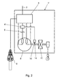
- the FIG. 2 shows a variant of an inventive Einphasenhubwerks 1 '.
- a semiconductor relay 4 ' is provided, which is speed-coupled to a rotating part.
- the semiconductor relay 4 ' is connected for signal transmission with a Drehbaum tone 14, which is arranged on the drive shaft 10 or other suitable rotating part.
- the speed pickup 14 is disposed between the electric motor (8) and the transmission 11. The speed pickup 14 determines the speed of the drive shaft 10 and transmits it to the semiconductor relay 4 'and the controller 3. If a predetermined speed of, for example, 2,500 per minute is reached, the semiconductor relay 4' automatically switches off the starting capacitor 5.
- a speed clutch is preferred over a time-delayed shutdown, but means by the installation of a Drehiere mecanics 14 a higher effort.
- the speed pickup 14 may be customary, for example, it can record the speed mechanically, electrically or, for example, magnetically or optically. Also in this embodiment, there is the advantage that the semiconductor relay 4 'switches without mechanically moving parts and therefore the life is much higher than in a mechanical switch, such as a centrifugal switch.
Abstract
Description
Die Erfindung betrifft ein Hubwerk mit einem einphasigen, aus Haupt- und Hilfswicklung bestehenden Elektromotor, einem mit der Hilfswicklung mittels Steuerung über einen Schalter zuschaltbar verbundenen Anlaufkondensator zur Simulation einer Phasenverschiebung in einer Startphase, wobei der Anlaufkondensator am Ende der Startphase durch den Schalter abgeschaltet wird.The invention relates to a hoist with a single-phase, consisting of main and auxiliary winding electric motor, a switchable connected to the auxiliary winding by means of control via a switch start-up capacitor for simulating a phase shift in a start phase, wherein the starting capacitor is switched off at the end of the start phase by the switch.
Hubwerke mit einphasigen Elektromotoren sind seit langem bekannt. Sie werden beispielsweise in Werkstätten zum Umschlag von Waren mit vergleichsweise geringem Gewicht verwendet. Sie kommen vor allem dort zum Einsatz, wo nur Einphasennetze vorhanden sind und somit die an sich vorteilhafteren Hubwerke mit dreiphasigen Motoren, auch Einphasenhubwerk genannt, nicht verwendet werden können. Dies ist weiterhin in verschiedenen Ländern der Fall.Hoists with single-phase electric motors have long been known. They are used for example in workshops for the handling of goods with relatively low weight. They are mainly used where only single-phase networks are available and thus the more advantageous hoists with three-phase motors, also called single-phase hoists, can not be used. This continues to be the case in different countries.
Gegenüber Hubwerken mit dreiphasigen Motoren besteht bei einfachen Hubwerken die Schwierigkeit, dass sie in der Regel einen Anlaufkondensator benötigen, der in der Startphase des Hubmotors eine Phasenverschiebung simuliert, die dem Motor ein erhöhtes Anlaufmoment zur Verfügung stellt. Ein Anfahren ist damit auch bei teilweise oder ganz angehobener Last möglich. Nach dem Anfahren muss dann jedoch der Anlaufkondensator mit einem geeigneten Schalter weggeschaltet werden, damit dieser nicht überladen wird und möglicherweise sogar explodiert.Compared to hoists with three-phase motors is the difficulty in simple hoists that they usually need a starting capacitor, which in the starting phase of the Stroke motor simulates a phase shift, which provides the motor an increased starting torque available. A start is thus possible even with partially or fully lifted load. After starting, however, then the starting capacitor must be switched off with a suitable switch so that it is not overloaded and may even explode.
Bei einem bekannten Einphasenhubwerk ist der genannte Schalter zum Wegschalten des Anlaufkondensators als Fliehkraftschalter ausgebildet. Dieser ist auf eine Antriebsachse aufgebaut. Erreicht die Antriebsachse eine vorbestimmte Drehzahl, so schaltet der Fliehkraftschalter den Anlaufkondensator selbsttätig ab. Die Abschaltdrehzahl beträgt beispielsweise 2'500 Umdrehungen pro Minute. In der Praxis hat sich dieses Einphasenhubwerk an sich bewährt.In a known Einphasenhubwerk said switch for switching off the starting capacitor is designed as a centrifugal force switch. This is built on a drive axle. If the drive axle reaches a predetermined speed, then the centrifugal force switch automatically shuts off the starting capacitor. The shutdown speed is for example 2'500 revolutions per minute. In practice, this Einphasenhubwerk has proven itself.
Aufgrund der grossen Ströme, die vom Fliehkraftschalter geschaltet werden müssen, ist die Lebensdauer des Fliehkraftschalters in einem solchen Einphasenhubwerk wesentlich kürzer als die Lebensdauer üblicher Einphasenhubwerke. Die Fliehkraftschalter müssen deshalb vergleichsweise häufig ausgewechselt werden. Beispielsweise können in einem Fliehkraftschalter die Kontakte verschweisst werden, und in der Folge kann der Anlaufkondensator überlastet und zerstört werden. Die defekten Bauteile müssen in diesem Fall vor dem weiteren Gebrauch ausgetauscht werden.Due to the large currents that must be switched by the centrifugal switch, the life of the centrifugal switch in such a Einphasenhubwerk is much shorter than the life of conventional Einphasenhubwerke. The centrifugal force switches must therefore be replaced comparatively frequently. For example, in a centrifugal switch, the contacts can be welded, and as a result, the starting capacitor can be overloaded and destroyed. The defective components must be replaced in this case before further use.
Bekannt ist auch die Verwendung von einstellbaren Zeitschaltrelais, welche in der Startphase nach einer bestimmten Zeitdauer von beispielsweise 0,5 Sekunden den Anlaufkondensator wegschalten. Solche Zeitrelais besitzen jedoch die gleichen Nachteile wie Fliehkraftschalter und müssen somit ebenfalls häufig ausgetauscht werden.Also known is the use of adjustable time relay, which switch off the starting capacitor in the startup phase after a certain period of time, for example, 0.5 seconds. However, such time relays have the same Disadvantages such as centrifugal force switches and thus must also be replaced frequently.
Der Erfindung liegt die Aufgabe zugrunde, ein Hubwerk mit einphasigem Motor der genannten Art zu schaffen, das die genannten Nachteile vermeidet. Das Hubwerk soll trotzdem kostengünstig herstellbar sein und eine hohe Funktionssicherheit aufweisen.The invention has for its object to provide a hoist with single-phase motor of the type mentioned, which avoids the disadvantages mentioned. The hoist should still be inexpensive to produce and have high reliability.
Die Aufgabe ist bei einem Hubwerk der genannten Art dadurch gelöst, dass der Schalter als Halbleiterrelais ausgebildet ist. Solche Relais werden auch als Solid State Relais (SSR) bezeichnet. Diese werden auch bei häufigem Schalten von hohen Strömen nicht beschädigt und sind damit auch bei einer Verwendung in einem Einphasenhubwerk über die übliche Lebensdauer solcher Einphasenhubwerke hinaus funktionstüchtig. Ein Auswechseln erübrigt sich damit. Solche Relais sind wesentlich kostengünstiger herstellbar als Fliehkraftschalter, so dass die Herstellungskosten von Einphasenhubwerken wesentlich gesenkt werden können.The object is achieved in a hoist of the type mentioned in that the switch is designed as a semiconductor relay. Such relays are also referred to as Solid State Relays (SSR). These are not damaged even with frequent switching of high currents and are therefore functional even when used in a Einphasenhubwerk over the usual life of such Einphasenhubwerke addition. Replacement is unnecessary. Such relays are much cheaper to produce than centrifugal switches, so that the manufacturing cost of Einphasenhubwerken can be significantly reduced.
Nach einer Weiterbildung der Erfindung ist vorgesehen, dass das Halbleiterrelais den Anlaufkondensator nach dem Ablauf einer bestimmten Zeitdauer wegschaltet. Diese Zeitdauer beträgt beispielsweise etwa 0,5 Sekunden. Es ist hier aber auch eine andere kürzere bzw. längere Abschaltzeitdauer denkbar. Alternativ ist auch eine Ausführung möglich, bei welcher das Halbleiterrelais den Anlaufkondensator beim Erreichen einer bestimmten Drehzahl wegschaltet.According to a development of the invention it is provided that the semiconductor relay switches off the starting capacitor after the expiration of a certain period of time. This time period is for example about 0.5 seconds. But it is also conceivable here another shorter or longer shutdown period. Alternatively, an embodiment is possible in which the semiconductor relay switches off the starting capacitor when a certain speed is reached.
Nach einer Weiterbildung der Erfindung ist vorgesehen, dass das Halbleiterrelais mit einer Antriebswelle gekoppelt ist. Vorzugsweise ist hierbei auf der Antriebswelle ein Drehzahlnehmer angeordnet, der mit dem Halbleiterrelais verbunden ist. Der Drehzahlnehmer übermittelt der Steuerung bzw. dem Halbleiterrelais die Drehzahl der Antriebswelle, so dass die Steuerung nach Erreichen einer vorbestimmten Drehzahl automatisch den Anlaufkondensator wegschaltet.According to a development of the invention, it is provided that the semiconductor relay is coupled to a drive shaft. Preferably, a speed sensor is arranged on the drive shaft, which is connected to the semiconductor relay. The speed sensor transmits the control or the semiconductor relay the speed of the drive shaft, so that the controller automatically switches off the starting capacitor after reaching a predetermined speed.
Der Drehzahlnehmer ist vorzugsweise zwischen dem einphasigen Hubmotor und einem Getriebe angeordnet. Das Einphasenhubwerk gemäss der vorliegenden Anmeldung eignet sich insbesondere als Kettenhubwerk.The speed sensor is preferably arranged between the single-phase hoist motor and a transmission. The single-phase hoist according to the present application is particularly suitable as a chain hoist.
Weitere vorteilhafte Merkmale ergeben sich aus den abhängigen Patentansprüchen, der nachfolgenden Beschreibung sowie der Zeichnung.Further advantageous features emerge from the dependent claims, the following description and the drawings.
Ausführungsbeispiele der Erfindung werden nachfolgend anhand der Zeichnung näher erläutert. Es zeigen:
- Fig. 1
- schematisch die Anlaufsteuerung eines erfindungsgemässen Hubwerks mit einphasigem Elektromotor,
- Fig. 2
- eine erfindungsgemässe Anlaufsteuerung gemäss einer Variante und
- Fig. 3
- eine räumliche Ansicht eines erfindungsgemässen Einphasenhubwerks, wobei Gehäuse weggelassen und die Steuerung ausgebaut ist.
- Fig. 1
- schematically the start-up control of a hoist according to the invention with a single-phase electric motor,
- Fig. 2
- an inventive start-up control according to a variant and
- Fig. 3
- a spatial view of an inventive Einphasenhubwerks, with housing omitted and the controller is removed.
Das in den
Zur Steuerung des Elektromotors 8 ist im Gehäuse 15 zudem eine Steuerung 3 angeordnet, die gemäss
Der Elekromotor 8 ist über die in
Die
Claims (6)
Priority Applications (1)
| Application Number | Priority Date | Filing Date | Title |
|---|---|---|---|
| EP07405144A EP1995205B1 (en) | 2007-05-21 | 2007-05-21 | Hoisting gear with a single-phase electric motor |
Applications Claiming Priority (1)
| Application Number | Priority Date | Filing Date | Title |
|---|---|---|---|
| EP07405144A EP1995205B1 (en) | 2007-05-21 | 2007-05-21 | Hoisting gear with a single-phase electric motor |
Publications (2)
| Publication Number | Publication Date |
|---|---|
| EP1995205A1 true EP1995205A1 (en) | 2008-11-26 |
| EP1995205B1 EP1995205B1 (en) | 2012-07-11 |
Family
ID=38582287
Family Applications (1)
| Application Number | Title | Priority Date | Filing Date |
|---|---|---|---|
| EP07405144A Not-in-force EP1995205B1 (en) | 2007-05-21 | 2007-05-21 | Hoisting gear with a single-phase electric motor |
Country Status (1)
| Country | Link |
|---|---|
| EP (1) | EP1995205B1 (en) |
Cited By (2)
| Publication number | Priority date | Publication date | Assignee | Title |
|---|---|---|---|---|
| EP2405567A1 (en) | 2010-07-09 | 2012-01-11 | Müller Martini Holding AG | Switch for operating a hoisting gear |
| DE102016116980B3 (en) * | 2016-09-09 | 2017-10-19 | Stahl Cranesystems Gmbh | Arrangement of a speed converter gear and at least one centrifugal switch, hoist with such an arrangement and method for testing a centrifugal switch |
Citations (5)
| Publication number | Priority date | Publication date | Assignee | Title |
|---|---|---|---|---|
| US3971971A (en) * | 1974-11-15 | 1976-07-27 | Ingersoll-Rand Company | Electric hoist control and braking system |
| GB2175467A (en) * | 1985-05-21 | 1986-11-26 | Pt Components Inc | Motor control circuit with automatic restart or cut-in |
| US4670697A (en) * | 1986-07-14 | 1987-06-02 | Pt Components, Inc. | Low cost, load and speed sensitive motor control starting circuit |
| US4751449A (en) * | 1986-09-24 | 1988-06-14 | Pt Components, Inc. | Start from coast protective circuit |
| EP0575045A2 (en) * | 1992-06-15 | 1993-12-22 | Elephant Chain Block Company Limited | Hoist machine |
-
2007
- 2007-05-21 EP EP07405144A patent/EP1995205B1/en not_active Not-in-force
Patent Citations (5)
| Publication number | Priority date | Publication date | Assignee | Title |
|---|---|---|---|---|
| US3971971A (en) * | 1974-11-15 | 1976-07-27 | Ingersoll-Rand Company | Electric hoist control and braking system |
| GB2175467A (en) * | 1985-05-21 | 1986-11-26 | Pt Components Inc | Motor control circuit with automatic restart or cut-in |
| US4670697A (en) * | 1986-07-14 | 1987-06-02 | Pt Components, Inc. | Low cost, load and speed sensitive motor control starting circuit |
| US4751449A (en) * | 1986-09-24 | 1988-06-14 | Pt Components, Inc. | Start from coast protective circuit |
| EP0575045A2 (en) * | 1992-06-15 | 1993-12-22 | Elephant Chain Block Company Limited | Hoist machine |
Cited By (2)
| Publication number | Priority date | Publication date | Assignee | Title |
|---|---|---|---|---|
| EP2405567A1 (en) | 2010-07-09 | 2012-01-11 | Müller Martini Holding AG | Switch for operating a hoisting gear |
| DE102016116980B3 (en) * | 2016-09-09 | 2017-10-19 | Stahl Cranesystems Gmbh | Arrangement of a speed converter gear and at least one centrifugal switch, hoist with such an arrangement and method for testing a centrifugal switch |
Also Published As
| Publication number | Publication date |
|---|---|
| EP1995205B1 (en) | 2012-07-11 |
Similar Documents
| Publication | Publication Date | Title |
|---|---|---|
| DE102010014644B4 (en) | Self-propelled work machine with an electric drive system and a method for operating such a system | |
| EP1901411B1 (en) | Method for actuating the motor of a battery driven tool | |
| DE102004021930A1 (en) | Method for operating a shut-off screwdriver and shut-off screwdriver | |
| AT398611B (en) | ELECTRIC MOTOR DRIVE FOR AN ACTUATOR | |
| DE2819942A1 (en) | ELECTRIC BRAKE MOTOR | |
| EP1995205B1 (en) | Hoisting gear with a single-phase electric motor | |
| DE3735396A1 (en) | PAPER SHREDDER | |
| WO2015082150A1 (en) | Electric lubricant pump comprising a connectable drive | |
| DE1155950B (en) | Electric motor drive for valves, slides or the like. | |
| DE69628673T2 (en) | ACTUATING DEVICE FOR AN ELECTRICAL SWITCHING DEVICE | |
| DE19811992A1 (en) | Circuit arrangement for controlling electric motor | |
| DE60025909T2 (en) | AN IMPROVEMENT IN A HOME SYSTEM FOR AN ELECTRIC ENGINE | |
| DE4119941A1 (en) | Protecting drive motor of electrical power tool - controlling zero voltage releaser and excess current releaser by drive current | |
| DE102017114316A1 (en) | Method for avoiding or delaying a short circuit in an electric motor | |
| DE3219633C2 (en) | ||
| EP2405567B1 (en) | Switch for operating a hoisting gear | |
| DE4008002C2 (en) | Method and device for controlling a motor-operated actuator | |
| DE2942793C2 (en) | Adjustment device driven by an electric motor | |
| EP2501938B1 (en) | Rotary pump arrangement having a controller and/or regulator | |
| DE19911429A1 (en) | Stopping electric motor operated with d.c. and/or a.c. current, especially for elevator, involves exchanging rotor winding connections within series circuit, short circuiting series windings | |
| DE545484C (en) | Device to prevent impermissible overloading of electrically driven hoists | |
| DE102005049351B4 (en) | Electromechanical overload protection and stroke limitation with limit switches for an electrically driven chain hoist | |
| EP0739086A1 (en) | Method and device for driving synchronous motors | |
| DE10226152A1 (en) | Circuit arrangement for operating a DC motor and adjusting device with such | |
| DE957496C (en) | Start-up and brake control for DC motors operated in Leonard circuit |
Legal Events
| Date | Code | Title | Description |
|---|---|---|---|
| PUAI | Public reference made under article 153(3) epc to a published international application that has entered the european phase |
Free format text: ORIGINAL CODE: 0009012 |
|
| AK | Designated contracting states |
Kind code of ref document: A1 Designated state(s): AT BE BG CH CY CZ DE DK EE ES FI FR GB GR HU IE IS IT LI LT LU LV MC MT NL PL PT RO SE SI SK TR |
|
| AX | Request for extension of the european patent |
Extension state: AL BA HR MK RS |
|
| 17P | Request for examination filed |
Effective date: 20090206 |
|
| 17Q | First examination report despatched |
Effective date: 20090302 |
|
| AKX | Designation fees paid |
Designated state(s): AT BE BG CH CY CZ DE DK EE ES FI FR GB GR HU IE IS IT LI LT LU LV MC MT NL PL PT RO SE SI SK TR |
|
| GRAP | Despatch of communication of intention to grant a patent |
Free format text: ORIGINAL CODE: EPIDOSNIGR1 |
|
| GRAS | Grant fee paid |
Free format text: ORIGINAL CODE: EPIDOSNIGR3 |
|
| GRAA | (expected) grant |
Free format text: ORIGINAL CODE: 0009210 |
|
| AK | Designated contracting states |
Kind code of ref document: B1 Designated state(s): AT BE BG CH CY CZ DE DK EE ES FI FR GB GR HU IE IS IT LI LT LU LV MC MT NL PL PT RO SE SI SK TR |
|
| REG | Reference to a national code |
Ref country code: GB Ref legal event code: FG4D Free format text: NOT ENGLISH |
|
| REG | Reference to a national code |
Ref country code: CH Ref legal event code: EP |
|
| REG | Reference to a national code |
Ref country code: AT Ref legal event code: REF Ref document number: 566030 Country of ref document: AT Kind code of ref document: T Effective date: 20120715 |
|
| REG | Reference to a national code |
Ref country code: IE Ref legal event code: FG4D Free format text: LANGUAGE OF EP DOCUMENT: GERMAN |
|
| REG | Reference to a national code |
Ref country code: DE Ref legal event code: R096 Ref document number: 502007010192 Country of ref document: DE Effective date: 20120906 |
|
| REG | Reference to a national code |
Ref country code: NL Ref legal event code: VDEP Effective date: 20120711 |
|
| REG | Reference to a national code |
Ref country code: LT Ref legal event code: MG4D Effective date: 20120711 |
|
| PG25 | Lapsed in a contracting state [announced via postgrant information from national office to epo] |
Ref country code: LT Free format text: LAPSE BECAUSE OF FAILURE TO SUBMIT A TRANSLATION OF THE DESCRIPTION OR TO PAY THE FEE WITHIN THE PRESCRIBED TIME-LIMIT Effective date: 20120711 Ref country code: FI Free format text: LAPSE BECAUSE OF FAILURE TO SUBMIT A TRANSLATION OF THE DESCRIPTION OR TO PAY THE FEE WITHIN THE PRESCRIBED TIME-LIMIT Effective date: 20120711 Ref country code: IS Free format text: LAPSE BECAUSE OF FAILURE TO SUBMIT A TRANSLATION OF THE DESCRIPTION OR TO PAY THE FEE WITHIN THE PRESCRIBED TIME-LIMIT Effective date: 20121111 Ref country code: CY Free format text: LAPSE BECAUSE OF FAILURE TO SUBMIT A TRANSLATION OF THE DESCRIPTION OR TO PAY THE FEE WITHIN THE PRESCRIBED TIME-LIMIT Effective date: 20120711 |
|
| PG25 | Lapsed in a contracting state [announced via postgrant information from national office to epo] |
Ref country code: PL Free format text: LAPSE BECAUSE OF FAILURE TO SUBMIT A TRANSLATION OF THE DESCRIPTION OR TO PAY THE FEE WITHIN THE PRESCRIBED TIME-LIMIT Effective date: 20120711 Ref country code: SI Free format text: LAPSE BECAUSE OF FAILURE TO SUBMIT A TRANSLATION OF THE DESCRIPTION OR TO PAY THE FEE WITHIN THE PRESCRIBED TIME-LIMIT Effective date: 20120711 Ref country code: LV Free format text: LAPSE BECAUSE OF FAILURE TO SUBMIT A TRANSLATION OF THE DESCRIPTION OR TO PAY THE FEE WITHIN THE PRESCRIBED TIME-LIMIT Effective date: 20120711 Ref country code: PT Free format text: LAPSE BECAUSE OF FAILURE TO SUBMIT A TRANSLATION OF THE DESCRIPTION OR TO PAY THE FEE WITHIN THE PRESCRIBED TIME-LIMIT Effective date: 20121112 Ref country code: GR Free format text: LAPSE BECAUSE OF FAILURE TO SUBMIT A TRANSLATION OF THE DESCRIPTION OR TO PAY THE FEE WITHIN THE PRESCRIBED TIME-LIMIT Effective date: 20121012 Ref country code: SE Free format text: LAPSE BECAUSE OF FAILURE TO SUBMIT A TRANSLATION OF THE DESCRIPTION OR TO PAY THE FEE WITHIN THE PRESCRIBED TIME-LIMIT Effective date: 20120711 |
|
| PG25 | Lapsed in a contracting state [announced via postgrant information from national office to epo] |
Ref country code: NL Free format text: LAPSE BECAUSE OF FAILURE TO SUBMIT A TRANSLATION OF THE DESCRIPTION OR TO PAY THE FEE WITHIN THE PRESCRIBED TIME-LIMIT Effective date: 20120711 |
|
| PG25 | Lapsed in a contracting state [announced via postgrant information from national office to epo] |
Ref country code: CZ Free format text: LAPSE BECAUSE OF FAILURE TO SUBMIT A TRANSLATION OF THE DESCRIPTION OR TO PAY THE FEE WITHIN THE PRESCRIBED TIME-LIMIT Effective date: 20120711 Ref country code: RO Free format text: LAPSE BECAUSE OF FAILURE TO SUBMIT A TRANSLATION OF THE DESCRIPTION OR TO PAY THE FEE WITHIN THE PRESCRIBED TIME-LIMIT Effective date: 20120711 Ref country code: EE Free format text: LAPSE BECAUSE OF FAILURE TO SUBMIT A TRANSLATION OF THE DESCRIPTION OR TO PAY THE FEE WITHIN THE PRESCRIBED TIME-LIMIT Effective date: 20120711 Ref country code: DK Free format text: LAPSE BECAUSE OF FAILURE TO SUBMIT A TRANSLATION OF THE DESCRIPTION OR TO PAY THE FEE WITHIN THE PRESCRIBED TIME-LIMIT Effective date: 20120711 Ref country code: ES Free format text: LAPSE BECAUSE OF FAILURE TO SUBMIT A TRANSLATION OF THE DESCRIPTION OR TO PAY THE FEE WITHIN THE PRESCRIBED TIME-LIMIT Effective date: 20121022 |
|
| PLBE | No opposition filed within time limit |
Free format text: ORIGINAL CODE: 0009261 |
|
| STAA | Information on the status of an ep patent application or granted ep patent |
Free format text: STATUS: NO OPPOSITION FILED WITHIN TIME LIMIT |
|
| PG25 | Lapsed in a contracting state [announced via postgrant information from national office to epo] |
Ref country code: IT Free format text: LAPSE BECAUSE OF FAILURE TO SUBMIT A TRANSLATION OF THE DESCRIPTION OR TO PAY THE FEE WITHIN THE PRESCRIBED TIME-LIMIT Effective date: 20120711 Ref country code: SK Free format text: LAPSE BECAUSE OF FAILURE TO SUBMIT A TRANSLATION OF THE DESCRIPTION OR TO PAY THE FEE WITHIN THE PRESCRIBED TIME-LIMIT Effective date: 20120711 |
|
| 26N | No opposition filed |
Effective date: 20130412 |
|
| PG25 | Lapsed in a contracting state [announced via postgrant information from national office to epo] |
Ref country code: BG Free format text: LAPSE BECAUSE OF FAILURE TO SUBMIT A TRANSLATION OF THE DESCRIPTION OR TO PAY THE FEE WITHIN THE PRESCRIBED TIME-LIMIT Effective date: 20121011 |
|
| REG | Reference to a national code |
Ref country code: DE Ref legal event code: R097 Ref document number: 502007010192 Country of ref document: DE Effective date: 20130412 |
|
| BERE | Be: lapsed |
Owner name: MULLER MARTINI HOLDING A.G. Effective date: 20130531 |
|
| PG25 | Lapsed in a contracting state [announced via postgrant information from national office to epo] |
Ref country code: MC Free format text: LAPSE BECAUSE OF FAILURE TO SUBMIT A TRANSLATION OF THE DESCRIPTION OR TO PAY THE FEE WITHIN THE PRESCRIBED TIME-LIMIT Effective date: 20120711 |
|
| REG | Reference to a national code |
Ref country code: IE Ref legal event code: MM4A |
|
| PG25 | Lapsed in a contracting state [announced via postgrant information from national office to epo] |
Ref country code: BE Free format text: LAPSE BECAUSE OF NON-PAYMENT OF DUE FEES Effective date: 20130531 |
|
| PG25 | Lapsed in a contracting state [announced via postgrant information from national office to epo] |
Ref country code: IE Free format text: LAPSE BECAUSE OF NON-PAYMENT OF DUE FEES Effective date: 20130521 |
|
| REG | Reference to a national code |
Ref country code: AT Ref legal event code: MM01 Ref document number: 566030 Country of ref document: AT Kind code of ref document: T Effective date: 20130521 |
|
| PG25 | Lapsed in a contracting state [announced via postgrant information from national office to epo] |
Ref country code: AT Free format text: LAPSE BECAUSE OF NON-PAYMENT OF DUE FEES Effective date: 20130521 |
|
| PG25 | Lapsed in a contracting state [announced via postgrant information from national office to epo] |
Ref country code: MT Free format text: LAPSE BECAUSE OF FAILURE TO SUBMIT A TRANSLATION OF THE DESCRIPTION OR TO PAY THE FEE WITHIN THE PRESCRIBED TIME-LIMIT Effective date: 20120711 |
|
| PG25 | Lapsed in a contracting state [announced via postgrant information from national office to epo] |
Ref country code: TR Free format text: LAPSE BECAUSE OF FAILURE TO SUBMIT A TRANSLATION OF THE DESCRIPTION OR TO PAY THE FEE WITHIN THE PRESCRIBED TIME-LIMIT Effective date: 20120711 |
|
| PG25 | Lapsed in a contracting state [announced via postgrant information from national office to epo] |
Ref country code: LU Free format text: LAPSE BECAUSE OF NON-PAYMENT OF DUE FEES Effective date: 20130521 Ref country code: HU Free format text: LAPSE BECAUSE OF FAILURE TO SUBMIT A TRANSLATION OF THE DESCRIPTION OR TO PAY THE FEE WITHIN THE PRESCRIBED TIME-LIMIT; INVALID AB INITIO Effective date: 20070521 |
|
| REG | Reference to a national code |
Ref country code: FR Ref legal event code: PLFP Year of fee payment: 10 |
|
| REG | Reference to a national code |
Ref country code: FR Ref legal event code: PLFP Year of fee payment: 11 |
|
| REG | Reference to a national code |
Ref country code: FR Ref legal event code: PLFP Year of fee payment: 12 |
|
| PGFP | Annual fee paid to national office [announced via postgrant information from national office to epo] |
Ref country code: DE Payment date: 20190524 Year of fee payment: 13 |
|
| PGFP | Annual fee paid to national office [announced via postgrant information from national office to epo] |
Ref country code: FR Payment date: 20190524 Year of fee payment: 13 |
|
| PGFP | Annual fee paid to national office [announced via postgrant information from national office to epo] |
Ref country code: GB Payment date: 20190524 Year of fee payment: 13 |
|
| PGFP | Annual fee paid to national office [announced via postgrant information from national office to epo] |
Ref country code: CH Payment date: 20190823 Year of fee payment: 13 |
|
| REG | Reference to a national code |
Ref country code: DE Ref legal event code: R119 Ref document number: 502007010192 Country of ref document: DE |
|
| PG25 | Lapsed in a contracting state [announced via postgrant information from national office to epo] |
Ref country code: LI Free format text: LAPSE BECAUSE OF NON-PAYMENT OF DUE FEES Effective date: 20200531 Ref country code: CH Free format text: LAPSE BECAUSE OF NON-PAYMENT OF DUE FEES Effective date: 20200531 |
|
| GBPC | Gb: european patent ceased through non-payment of renewal fee |
Effective date: 20200521 |
|
| PG25 | Lapsed in a contracting state [announced via postgrant information from national office to epo] |
Ref country code: GB Free format text: LAPSE BECAUSE OF NON-PAYMENT OF DUE FEES Effective date: 20200521 Ref country code: FR Free format text: LAPSE BECAUSE OF NON-PAYMENT OF DUE FEES Effective date: 20200531 |
|
| PG25 | Lapsed in a contracting state [announced via postgrant information from national office to epo] |
Ref country code: DE Free format text: LAPSE BECAUSE OF NON-PAYMENT OF DUE FEES Effective date: 20201201 |