EP1995434A1 - Control method in the case of a fault in an internal combustion engine fitted with a servo-assisted butterfly valve - Google Patents
Control method in the case of a fault in an internal combustion engine fitted with a servo-assisted butterfly valve Download PDFInfo
- Publication number
- EP1995434A1 EP1995434A1 EP07425324A EP07425324A EP1995434A1 EP 1995434 A1 EP1995434 A1 EP 1995434A1 EP 07425324 A EP07425324 A EP 07425324A EP 07425324 A EP07425324 A EP 07425324A EP 1995434 A1 EP1995434 A1 EP 1995434A1
- Authority
- EP
- European Patent Office
- Prior art keywords
- electric drive
- control unit
- electronic control
- case
- butterfly valve
- Prior art date
- Legal status (The legal status is an assumption and is not a legal conclusion. Google has not performed a legal analysis and makes no representation as to the accuracy of the status listed.)
- Withdrawn
Links
Images

Classifications
-
- F—MECHANICAL ENGINEERING; LIGHTING; HEATING; WEAPONS; BLASTING
- F02—COMBUSTION ENGINES; HOT-GAS OR COMBUSTION-PRODUCT ENGINE PLANTS
- F02D—CONTROLLING COMBUSTION ENGINES
- F02D11/00—Arrangements for, or adaptations to, non-automatic engine control initiation means, e.g. operator initiated
- F02D11/06—Arrangements for, or adaptations to, non-automatic engine control initiation means, e.g. operator initiated characterised by non-mechanical control linkages, e.g. fluid control linkages or by control linkages with power drive or assistance
- F02D11/10—Arrangements for, or adaptations to, non-automatic engine control initiation means, e.g. operator initiated characterised by non-mechanical control linkages, e.g. fluid control linkages or by control linkages with power drive or assistance of the electric type
- F02D11/107—Safety-related aspects
-
- F—MECHANICAL ENGINEERING; LIGHTING; HEATING; WEAPONS; BLASTING
- F02—COMBUSTION ENGINES; HOT-GAS OR COMBUSTION-PRODUCT ENGINE PLANTS
- F02D—CONTROLLING COMBUSTION ENGINES
- F02D11/00—Arrangements for, or adaptations to, non-automatic engine control initiation means, e.g. operator initiated
- F02D11/06—Arrangements for, or adaptations to, non-automatic engine control initiation means, e.g. operator initiated characterised by non-mechanical control linkages, e.g. fluid control linkages or by control linkages with power drive or assistance
- F02D11/10—Arrangements for, or adaptations to, non-automatic engine control initiation means, e.g. operator initiated characterised by non-mechanical control linkages, e.g. fluid control linkages or by control linkages with power drive or assistance of the electric type
- F02D2011/101—Arrangements for, or adaptations to, non-automatic engine control initiation means, e.g. operator initiated characterised by non-mechanical control linkages, e.g. fluid control linkages or by control linkages with power drive or assistance of the electric type characterised by the means for actuating the throttles
- F02D2011/102—Arrangements for, or adaptations to, non-automatic engine control initiation means, e.g. operator initiated characterised by non-mechanical control linkages, e.g. fluid control linkages or by control linkages with power drive or assistance of the electric type characterised by the means for actuating the throttles at least one throttle being moved only by an electric actuator
-
- F—MECHANICAL ENGINEERING; LIGHTING; HEATING; WEAPONS; BLASTING
- F02—COMBUSTION ENGINES; HOT-GAS OR COMBUSTION-PRODUCT ENGINE PLANTS
- F02D—CONTROLLING COMBUSTION ENGINES
- F02D41/00—Electrical control of supply of combustible mixture or its constituents
- F02D41/22—Safety or indicating devices for abnormal conditions
- F02D2041/227—Limping Home, i.e. taking specific engine control measures at abnormal conditions
-
- F—MECHANICAL ENGINEERING; LIGHTING; HEATING; WEAPONS; BLASTING
- F02—COMBUSTION ENGINES; HOT-GAS OR COMBUSTION-PRODUCT ENGINE PLANTS
- F02D—CONTROLLING COMBUSTION ENGINES
- F02D2200/00—Input parameters for engine control
- F02D2200/60—Input parameters for engine control said parameters being related to the driver demands or status
- F02D2200/602—Pedal position
Definitions
- the present invention concerns a control method in the case of a fault in an internal combustion engine fitted with a servo-assisted butterfly valve.
- the present invention finds useful application in the control of an internal combustion engine of a motor vehicle (or rather, a two-wheeled vehicle), to which the following description will make explicit reference, but without any loss in generality.
- DBW Drive By Wire
- an electronic control unit which receives readings from a position sensor that detects the position of the accelerator and operates an electric actuator that controls an electric drive that pilots the butterfly valve's actuator.
- a particularly dangerous fault that would normally impose immediate switching off of the engine (or rather the halting of the motor vehicle) is the disconnection of the cable that connects the electronic control unit to the electric drive that pilots the butterfly valve's actuator, as in this situation the electronic control unit is no longer able to control the position of the butterfly valve.
- the object of the present invention is to provide a control method in the case of a fault in an internal combustion engine fitted with a servo-assisted butterfly valve, this control method being of easy and economic embodiment and allowing the vehicle to continue to be driven with reduced performance in order to autonomously reach a service centre.
- a control method is provided in the case of a fault in an internal combustion engine fitted with a servo-assisted butterfly valve according to that claimed in the attached claims.
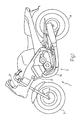
- reference numeral 1 indicates a motorcycle as a whole, comprising a chassis 2 that supports a front wheel 3 via a front suspension, a rear wheel 4 via a rear suspension and a petrol-fuelled internal combustion engine 5.
- the internal combustion engine 5 is fitted with a number of cylinders 6 (only one of which is shown in Figure 2 ), each of which is connected to an intake manifold 7 via two intake valves 8 (only one of which is shown in Figure 2 ) and an exhaust manifold 9 via two exhaust valves 10 (only one of which is shown in Figure 2 ).
- the intake manifold 7 receives fresh air (or rather air coming from the outside environment) through a feed duct 11 regulated by a butterfly valve 12 and is connected to the cylinders 6 via respective intake ports 13 (only one of which is shown in Figure 2 ), each of which is regulated by the corresponding intake valves 8.
- the exhaust manifold 9 is connected to the cylinders 6 via respective exhaust ports 14 (only one of which is shown in Figure 2 ), each of which is regulated by the corresponding exhaust valves 10; an exhaust pipe 15, terminating in a silencer, runs from the exhaust manifold 9 to discharge the gases produced by combustion into the atmosphere.
- Each cylinder 6 includes a spark plug 16, which is positioned at the top the cylinder 6 and is cyclically piloted to ignite the mixture at the end of the compression phase (that is in correspondence to TDC - Top Dead Centre).
- the fuel or rather the petrol
- the injectors 17 are positioned in a manner to inject fuel directly into each cylinder 6.
- An electronic control unit 18 superintends the running of the internal combustion engine 5, piloting the injectors 17 and the spark plugs 16.
- the electronic control unit 18 implements a DBW (Drive By Wire) system; in consequence, the butterfly valve 12 is servo-controlled and is operated by an electric actuator 19 that is controlled by the electronic control unit 18 according to the signals received from a position sensor 20, which detects the position of an accelerator 21 of the motorcycle 1 in real time.
- the position sensor 20 has at least two mutually redundant potentiometers, so that the reading provided by a potentiometer can always be confirmed by the reading provided by the other potentiometer.
- the electronic control unit 18 is connected by an electric cable 22 to the position sensor 20 and is connected by a CAN/BUS type electric cable 23 to an electric drive 24 that pilots the electric actuator 19; in other words, the electronic control unit 18 sends the desired position for the butterfly valve 12 to the electric drive 24 via the AN/BUS type electric cable 23 and the electric drive 24 supplies the necessary electric current (via a feedback control) to the electric actuator 19 to set the butterfly valve 12 in the desired position.
- the electronic control unit 18 is connected to the electric drive 24 via an additional electric cable 25 that the switching on and off of the electric drive 24.
- the electronic control unit 18 is also connected to a speed sensor 26, which determines the speed (or rather the number of revolutions) of the internal combustion engine 5.
- the electronic control unit 18 includes a plurality of diagnostic algorithms that are cyclically executed to determine the onset of possible faults in components of the motorcycle 1. Some faults do not involve the main components of the motorcycle 1 and are therefore just signalled to the rider of the motorcycle 1 by the turning on of a specially provided warning light on the instrument panel 27. Instead, other faults involve the main components of the motorcycle 1 and render driving at full performance dangerous for the rider and/or mechanics, whilst driving the motorcycle 1 with reduced performance is possible (or rather, fairly safe) in order to reach a service centre with the motorcycle 1.
- the electronic control unit 18 and possibly the electric drive 24 as well cyclically check the correct functioning of the connection between the electronic control unit 18 and the electric drive 24. If an interruption in the connection between the electronic control unit 18 and the electric drive 24 occurs, the electronic control unit 18 is no longer able to communicate the desired position for the butterfly valve 12 to the electric drive 24; in this situation, the electric drive 24 is switched off so that the butterfly valve 12 sets itself in a predefined limp-home position and the internal combustion engine 5 is piloted to keep the number of revs constant and equal to a predefined and calibratable emergency value (for example, between 2000 and 3000 rpm).
- a predefined and calibratable emergency value for example, between 2000 and 3000 rpm
- the electronic control unit 18 With respect to normal running, to keep the number of revs constant and equal to the predefined emergency value, the electronic control unit 18 normally cuts the injection of fuel (i.e. it acts on the injectors 17) and/or stops the ignition spark for the mixture inside the cylinder 6 (i.e. it acts on the spark plugs 16).
- the quantity of limp-home air that is made to pass through the butterfly valve 12 in the limp-home position is determined in advance and this quantity of limp-home air is stored in the electronic control unit 18; therefore, in the case of interruption of the connection between the electronic control unit 18 and the electric drive 24, the quantity of fuel to inject via the injectors 17 is determined in function of the effective number of revs (or rather, the difference between the effective number of revs and the desired number of revs, equal to the predefined emergency value) and in function of the quantity of limp-home air. In this way, it is possible to avoid feeding the cylinders 6 with an excessively rich mixture (i.e. with too much fuel in relation to the air present) or an excessively lean (i.e. with too little fuel in relation to the air present) mixture.
- the electronic control unit 18 sends a switch-off command to the electric drive 24 using the electric cable 25 that controls the switching on and off of the electric drive 24.
- the electric drive 24 could autonomously switch itself off without requiring and/or awaiting a special command from the electronic control unit 18; this possibility renders the system more robust, as it is unaffected by a possible break in the electric cable 25 as well.
- the electric drive 24 could require a non-zero electrical voltage on the electric cable 25 and therefore, in the case of the electric cable 25 breaking, the electric drive 24 would autonomously and automatically switch itself off.
- the above-described control method for the internal combustion engine 5 in the case of interruption of the connection between the electronic control unit 18 and the electric drive 24 offers numerous advantages, as it is simple and economic to produce, provides a high level of safety for the rider of the motorcycle 1 and allows the rider of the motorcycle 1 to ride the motorcycle 1 (obviously at reduced speed) to a service centre without needing to call a tow truck.
Abstract
Control method in the case of a fault in an internal combustion engine (5); the control method provides for the phases of: cyclically checking the correct functioning of a connection between an electronic control unit (18) and an electric drive (24) of an electric actuator (19) coupled to a butterfly valve (12) to control the position of the same butterfly valve (12), switching off the electric drive (24) in the case of interruption in the connection between the electronic control unit (18) and the electric drive (24) so that the butterfly valve (12) sets itself in a predefined limp-home position, and piloting the engine (5) in the case of interruption in the connection between the electronic control unit (18) and the electric drive (24) to keep the number of revs constant and equal to a predefined emergency value.
The electric drive switches off autonomously or via a second electric cable between the ECU and the electric drive.
The electric drive switches off autonomously or via a second electric cable between the ECU and the electric drive.
Description
- The present invention concerns a control method in the case of a fault in an internal combustion engine fitted with a servo-assisted butterfly valve.
- The present invention finds useful application in the control of an internal combustion engine of a motor vehicle (or rather, a two-wheeled vehicle), to which the following description will make explicit reference, but without any loss in generality.
- Electronics, both passive (sensors to detect control quantities) and active (actuators for directly operating mechanical components), are increasingly present in modern motor vehicles. For example, virtually all motor vehicles have electronic injection, namely fuel injectors that are operated by electric actuators piloted by an electronic control unit, and are fitted with a lambda sensor, or rather a probe able to detect the composition of the exhaust gas. Recently, the application of DBW (Drive By Wire) systems has been proposed, in which the accelerator is no longer mechanically connected to the engine throttle control, but is only connected to a position sensor that detects the position of the accelerator and, in consequence, pilots an actuator that mechanically operated the butterfly valve.
- DBW (Drive By Wire) systems are provided with an electronic control unit, which receives readings from a position sensor that detects the position of the accelerator and operates an electric actuator that controls an electric drive that pilots the butterfly valve's actuator. A particularly dangerous fault that would normally impose immediate switching off of the engine (or rather the halting of the motor vehicle) is the disconnection of the cable that connects the electronic control unit to the electric drive that pilots the butterfly valve's actuator, as in this situation the electronic control unit is no longer able to control the position of the butterfly valve.
- The object of the present invention is to provide a control method in the case of a fault in an internal combustion engine fitted with a servo-assisted butterfly valve, this control method being of easy and economic embodiment and allowing the vehicle to continue to be driven with reduced performance in order to autonomously reach a service centre.
- In accordance with the present invention, a control method is provided in the case of a fault in an internal combustion engine fitted with a servo-assisted butterfly valve according to that claimed in the attached claims.
- The present invention shall now be described with reference to the attached drawings, which illustrate a non-limitative example of embodiment, in which:
-
Figure 1 is a schematic view of a motorcycle that implements the present invention's control method in the case of a fault, and -
Figure 2 is a schematic view of an internal combustion engine of the motorcycle inFigure 1 . - In
Figure 1 , reference numeral 1 indicates a motorcycle as a whole, comprising achassis 2 that supports a front wheel 3 via a front suspension, a rear wheel 4 via a rear suspension and a petrol-fuelledinternal combustion engine 5. - As shown in
Figure 2 , theinternal combustion engine 5 is fitted with a number of cylinders 6 (only one of which is shown inFigure 2 ), each of which is connected to an intake manifold 7 via two intake valves 8 (only one of which is shown inFigure 2 ) and anexhaust manifold 9 via two exhaust valves 10 (only one of which is shown inFigure 2 ). - The intake manifold 7 receives fresh air (or rather air coming from the outside environment) through a
feed duct 11 regulated by abutterfly valve 12 and is connected to thecylinders 6 via respective intake ports 13 (only one of which is shown inFigure 2 ), each of which is regulated by thecorresponding intake valves 8. Similarly, theexhaust manifold 9 is connected to thecylinders 6 via respective exhaust ports 14 (only one of which is shown inFigure 2 ), each of which is regulated by thecorresponding exhaust valves 10; anexhaust pipe 15, terminating in a silencer, runs from theexhaust manifold 9 to discharge the gases produced by combustion into the atmosphere. - Each
cylinder 6 includes aspark plug 16, which is positioned at the top thecylinder 6 and is cyclically piloted to ignite the mixture at the end of the compression phase (that is in correspondence to TDC - Top Dead Centre). According to the embodiment shown inFigure 2 , the fuel (or rather the petrol) is injected inside eachintake port 13 via arespective injector 17 positioned close to thecorresponding intake valves 8. According to another embodiment, not shown, theinjectors 17 are positioned in a manner to inject fuel directly into eachcylinder 6. - An
electronic control unit 18 superintends the running of theinternal combustion engine 5, piloting theinjectors 17 and thespark plugs 16. In addition, theelectronic control unit 18 implements a DBW (Drive By Wire) system; in consequence, thebutterfly valve 12 is servo-controlled and is operated by anelectric actuator 19 that is controlled by theelectronic control unit 18 according to the signals received from aposition sensor 20, which detects the position of anaccelerator 21 of the motorcycle 1 in real time. For safety reasons, theposition sensor 20 has at least two mutually redundant potentiometers, so that the reading provided by a potentiometer can always be confirmed by the reading provided by the other potentiometer. - According to the embodiment shown in
Figure 2 , theelectronic control unit 18 is connected by anelectric cable 22 to theposition sensor 20 and is connected by a CAN/BUS typeelectric cable 23 to anelectric drive 24 that pilots theelectric actuator 19; in other words, theelectronic control unit 18 sends the desired position for thebutterfly valve 12 to theelectric drive 24 via the AN/BUS typeelectric cable 23 and theelectric drive 24 supplies the necessary electric current (via a feedback control) to theelectric actuator 19 to set thebutterfly valve 12 in the desired position. According to the embodiment shown inFigure 2 , theelectronic control unit 18 is connected to theelectric drive 24 via an additionalelectric cable 25 that the switching on and off of theelectric drive 24. Theelectronic control unit 18 is also connected to aspeed sensor 26, which determines the speed (or rather the number of revolutions) of theinternal combustion engine 5. - The
electronic control unit 18 includes a plurality of diagnostic algorithms that are cyclically executed to determine the onset of possible faults in components of the motorcycle 1. Some faults do not involve the main components of the motorcycle 1 and are therefore just signalled to the rider of the motorcycle 1 by the turning on of a specially provided warning light on theinstrument panel 27. Instead, other faults involve the main components of the motorcycle 1 and render driving at full performance dangerous for the rider and/or mechanics, whilst driving the motorcycle 1 with reduced performance is possible (or rather, fairly safe) in order to reach a service centre with the motorcycle 1. - In particular, the
electronic control unit 18 and possibly theelectric drive 24 as well, cyclically check the correct functioning of the connection between theelectronic control unit 18 and theelectric drive 24. If an interruption in the connection between theelectronic control unit 18 and theelectric drive 24 occurs, theelectronic control unit 18 is no longer able to communicate the desired position for thebutterfly valve 12 to theelectric drive 24; in this situation, theelectric drive 24 is switched off so that thebutterfly valve 12 sets itself in a predefined limp-home position and theinternal combustion engine 5 is piloted to keep the number of revs constant and equal to a predefined and calibratable emergency value (for example, between 2000 and 3000 rpm). - With respect to normal running, to keep the number of revs constant and equal to the predefined emergency value, the
electronic control unit 18 normally cuts the injection of fuel (i.e. it acts on the injectors 17) and/or stops the ignition spark for the mixture inside the cylinder 6 (i.e. it acts on the spark plugs 16). - During the design phase of the
internal combustion engine 5 the quantity of limp-home air that is made to pass through thebutterfly valve 12 in the limp-home position is determined in advance and this quantity of limp-home air is stored in theelectronic control unit 18; therefore, in the case of interruption of the connection between theelectronic control unit 18 and theelectric drive 24, the quantity of fuel to inject via theinjectors 17 is determined in function of the effective number of revs (or rather, the difference between the effective number of revs and the desired number of revs, equal to the predefined emergency value) and in function of the quantity of limp-home air. In this way, it is possible to avoid feeding thecylinders 6 with an excessively rich mixture (i.e. with too much fuel in relation to the air present) or an excessively lean (i.e. with too little fuel in relation to the air present) mixture. - Normally, in the case of interruption of the connection between the
electronic control unit 18 and the electric drive 24 (i.e. in the case of interruption of the CAN/BUS type electric cable 23), theelectronic control unit 18 sends a switch-off command to theelectric drive 24 using theelectric cable 25 that controls the switching on and off of theelectric drive 24. Obviously, in the case of interruption of the connection between theelectronic control unit 18 and the electric drive 24 (i.e. in the case of interruption of the CAN/BUS type electric cable 23), theelectric drive 24 could autonomously switch itself off without requiring and/or awaiting a special command from theelectronic control unit 18; this possibility renders the system more robust, as it is unaffected by a possible break in theelectric cable 25 as well. Alternatively, in order to remain on, theelectric drive 24 could require a non-zero electrical voltage on theelectric cable 25 and therefore, in the case of theelectric cable 25 breaking, theelectric drive 24 would autonomously and automatically switch itself off. - The above-described control method for the
internal combustion engine 5 in the case of interruption of the connection between theelectronic control unit 18 and theelectric drive 24 offers numerous advantages, as it is simple and economic to produce, provides a high level of safety for the rider of the motorcycle 1 and allows the rider of the motorcycle 1 to ride the motorcycle 1 (obviously at reduced speed) to a service centre without needing to call a tow truck.
Claims (8)
- Control method in the case of a fault on an internal combustion engine (5) comprising:at least one cylinder (6),at least one injector (17) to inject fuel,at least one butterfly valve (12) to regulate the flow of air sucked into the cylinder (6),a position sensor (20) to determine the position of an accelerator control,an electric actuator (19) coupled to the butterfly valve (12) to control the position of the butterfly valve (12),an electric drive (24) to pilot the electric actuator (19), andan electronic control unit (18), which is connected to the position sensor (20) for reading the position of the accelerator control and is connected to the electric drive (24) to send a desired position value for the butterfly valve (12) to the same electric drive (24);the control method is characterized in comprising the phases of:cyclically checking the correct functioning of the connection between the electronic control unit (18) and the electric drive (24);switching off the electric drive (24), in the case of interruption in the connection between the electronic control unit (18) and the electric drive (24), so that the butterfly valve (12) sets itself in a predefined limp-home position; andpiloting the engine (5), in the case of interruption in the connection between the electronic control unit (18) and the electric drive (24), to keep the number of revs constant and equal to a predefined emergency value.
- Control method according to claim 1 and including the additional phases of:determining in advance a quantity of limp-home air that is made to pass through the butterfly valve (12) in the limp-home position; anddetermining, in the case of interruption in the connection between the electronic control unit (18) and the electric drive (24), a quantity of fuel to inject in function of the number of revs and in function of the quantity of limp-home air.
- Control method according to claim 1 or 2, wherein the electronic control unit (18) is connected to the electric drive (24) via a first electric cable (23) of the CAN/BUS type.
- Control method according to claim 3, wherein the electronic control unit (18) is also connected to the electric drive (24) via a second electric cable (25) that controls the switching on and off of the electric drive (24).
- Control method according to one of the claims 1 to 4, wherein, in the case of interruption in the connection between the electronic control unit (18) and the electric drive (24), the electronic control unit (18) sends a switch-off command to the electric drive (24).
- Control method according to one of the claims 1 to 4, wherein, in the case of interruption in the connection between the electronic control unit (18) and the electric drive (24), the electric drive (24) autonomously switches itself off.
- Control method according to one of the claims 1 to 6, wherein, in the case of interruption in the connection between the electronic control unit (18) and the electric drive (24), the number of revs is kept constant and equal to the predefined emergency value by cutting the injection of fuel.
- Control method according to one of the claims 1 to 7, wherein, in the case of interruption in the connection between the electronic control unit (18) and the electric drive (24), the number of revs is kept constant and equal to the predefined emergency value by interrupting the ignition spark for the mixture inside the cylinder (6).
Priority Applications (4)
| Application Number | Priority Date | Filing Date | Title |
|---|---|---|---|
| EP07425324A EP1995434A1 (en) | 2007-05-25 | 2007-05-25 | Control method in the case of a fault in an internal combustion engine fitted with a servo-assisted butterfly valve |
| US12/125,286 US7789067B2 (en) | 2007-05-25 | 2008-05-22 | Control method in the case of a fault in an internal combustion engine fitted with a servo-assisted butterfly valve |
| BRPI0801632-1A BRPI0801632A2 (en) | 2007-05-25 | 2008-05-23 | control method in the event of a failure in an internal combustion engine equipped with a servo-assisted butterfly valve |
| CNA2008100989916A CN101311514A (en) | 2007-05-25 | 2008-05-26 | Control method in the case of a fault in an internal combustion engine fitted with a servo-assisted butterfly valve |
Applications Claiming Priority (1)
| Application Number | Priority Date | Filing Date | Title |
|---|---|---|---|
| EP07425324A EP1995434A1 (en) | 2007-05-25 | 2007-05-25 | Control method in the case of a fault in an internal combustion engine fitted with a servo-assisted butterfly valve |
Publications (1)
| Publication Number | Publication Date |
|---|---|
| EP1995434A1 true EP1995434A1 (en) | 2008-11-26 |
Family
ID=39370955
Family Applications (1)
| Application Number | Title | Priority Date | Filing Date |
|---|---|---|---|
| EP07425324A Withdrawn EP1995434A1 (en) | 2007-05-25 | 2007-05-25 | Control method in the case of a fault in an internal combustion engine fitted with a servo-assisted butterfly valve |
Country Status (4)
| Country | Link |
|---|---|
| US (1) | US7789067B2 (en) |
| EP (1) | EP1995434A1 (en) |
| CN (1) | CN101311514A (en) |
| BR (1) | BRPI0801632A2 (en) |
Families Citing this family (3)
| Publication number | Priority date | Publication date | Assignee | Title |
|---|---|---|---|---|
| EP1995436B1 (en) * | 2007-05-25 | 2010-07-07 | Magneti Marelli S.p.A. | Control method for a motorized vehicle in the case of a fault that advices/imposes driving the vehicle with reduced performance |
| US11552582B2 (en) | 2020-06-15 | 2023-01-10 | Woodward, Inc. | Setpoint identification on retrofit electric actuation |
| US11694876B2 (en) | 2021-12-08 | 2023-07-04 | Applied Materials, Inc. | Apparatus and method for delivering a plurality of waveform signals during plasma processing |
Citations (6)
| Publication number | Priority date | Publication date | Assignee | Title |
|---|---|---|---|---|
| GB2226658A (en) * | 1988-12-30 | 1990-07-04 | Bosch Gmbh Robert | Controlling vehicle engine after malfunction |
| US5601063A (en) * | 1995-02-02 | 1997-02-11 | Nippondenso Co., Ltd. | Fail-safe engine accelerator-throttle control |
| US6230094B1 (en) * | 1998-04-13 | 2001-05-08 | Denso Corporation | Electronic control system and method having monitor program |
| US6267099B1 (en) * | 1996-09-03 | 2001-07-31 | Hitachi, Ltd. | Throttle valve control device for an internal combustion engine |
| EP1178204A2 (en) * | 2000-08-03 | 2002-02-06 | Honda Giken Kogyo Kabushiki Kaisha | Controller for controlling an internal combustion engine in emergency driving |
| US20030094157A1 (en) * | 2001-11-20 | 2003-05-22 | Honda Giken Kogyo Kabushiki Kaisha | Power output control system for internal combustion engine |
Family Cites Families (5)
| Publication number | Priority date | Publication date | Assignee | Title |
|---|---|---|---|---|
| US5629852A (en) * | 1993-02-26 | 1997-05-13 | Mitsubishi Denki Kabushiki Kaisha | Vehicle control device for controlling output power of multi-cylinder engine upon emergency |
| US5857998A (en) * | 1994-06-30 | 1999-01-12 | Boston Scientific Corporation | Stent and therapeutic delivery system |
| NL1005174C2 (en) * | 1997-02-04 | 1998-08-06 | Oce Tech Bv | Ink composition for a fusible ink. |
| US20020107504A1 (en) * | 2001-02-06 | 2002-08-08 | Gordon Lucas S. | Apparatus for local drug delivery in limb |
| US8876754B2 (en) * | 2006-08-31 | 2014-11-04 | Bayer Medical Care Inc. | Catheter with filtering and sensing elements |
-
2007
- 2007-05-25 EP EP07425324A patent/EP1995434A1/en not_active Withdrawn
-
2008
- 2008-05-22 US US12/125,286 patent/US7789067B2/en not_active Expired - Fee Related
- 2008-05-23 BR BRPI0801632-1A patent/BRPI0801632A2/en not_active Application Discontinuation
- 2008-05-26 CN CNA2008100989916A patent/CN101311514A/en active Pending
Patent Citations (6)
| Publication number | Priority date | Publication date | Assignee | Title |
|---|---|---|---|---|
| GB2226658A (en) * | 1988-12-30 | 1990-07-04 | Bosch Gmbh Robert | Controlling vehicle engine after malfunction |
| US5601063A (en) * | 1995-02-02 | 1997-02-11 | Nippondenso Co., Ltd. | Fail-safe engine accelerator-throttle control |
| US6267099B1 (en) * | 1996-09-03 | 2001-07-31 | Hitachi, Ltd. | Throttle valve control device for an internal combustion engine |
| US6230094B1 (en) * | 1998-04-13 | 2001-05-08 | Denso Corporation | Electronic control system and method having monitor program |
| EP1178204A2 (en) * | 2000-08-03 | 2002-02-06 | Honda Giken Kogyo Kabushiki Kaisha | Controller for controlling an internal combustion engine in emergency driving |
| US20030094157A1 (en) * | 2001-11-20 | 2003-05-22 | Honda Giken Kogyo Kabushiki Kaisha | Power output control system for internal combustion engine |
Also Published As
| Publication number | Publication date |
|---|---|
| BRPI0801632A2 (en) | 2010-01-12 |
| US7789067B2 (en) | 2010-09-07 |
| US20090000594A1 (en) | 2009-01-01 |
| CN101311514A (en) | 2008-11-26 |
Similar Documents
| Publication | Publication Date | Title |
|---|---|---|
| US6647959B2 (en) | Fail-safe device for electronic throttle control system | |
| US6073610A (en) | Control apparatus of internal combustion engine equipped with electronic throttle control device | |
| US6047679A (en) | Control apparatus for an internal combustion engine | |
| US6964260B2 (en) | Electronic engine control device | |
| US7997251B2 (en) | Systems and methods for electronic throttle control | |
| KR100318527B1 (en) | Control unit of vehicle | |
| JP3694406B2 (en) | Fail-safe control device for electric throttle type internal combustion engine | |
| JP2005155339A (en) | Control device for internal combustion engine | |
| JP2007092623A (en) | Engine for leisure vehicle | |
| US7789067B2 (en) | Control method in the case of a fault in an internal combustion engine fitted with a servo-assisted butterfly valve | |
| US20140366835A1 (en) | Avoidance of a safety fuel cut-off during partial engine operation | |
| US6295967B1 (en) | Powertrain output monitor | |
| KR20130107773A (en) | System and control method of the diesel-gas dual-fuel engine | |
| JP2009036036A (en) | Ignition timing control device of internal combustion engine | |
| EP1995436B1 (en) | Control method for a motorized vehicle in the case of a fault that advices/imposes driving the vehicle with reduced performance | |
| US8843297B2 (en) | Rpm control device and rpm control method for a general-purpose engine | |
| KR102012337B1 (en) | Apparatus for diagnosing malfunction of internal combustion engine and method thereof | |
| JP2000054867A (en) | Fail-safe control device for electronically controlled throttle type internal combustion engine | |
| JP2003083137A (en) | Control device for internal combustion engine | |
| JP2535799B2 (en) | Output control device for internal combustion engine | |
| JP2005009365A (en) | Cylinder deactivation control device | |
| JP3967423B2 (en) | Vehicle control device | |
| KR100929454B1 (en) | Method for controlling internal combustion engine | |
| JP2009162140A (en) | Aircraft engine having electronic throttle | |
| JP2017115694A (en) | Control mechanism of purge valve |
Legal Events
| Date | Code | Title | Description |
|---|---|---|---|
| PUAI | Public reference made under article 153(3) epc to a published international application that has entered the european phase |
Free format text: ORIGINAL CODE: 0009012 |
|
| AK | Designated contracting states |
Kind code of ref document: A1 Designated state(s): AT BE BG CH CY CZ DE DK EE ES FI FR GB GR HU IE IS IT LI LT LU LV MC MT NL PL PT RO SE SI SK TR |
|
| AX | Request for extension of the european patent |
Extension state: AL BA HR MK RS |
|
| AKX | Designation fees paid | ||
| REG | Reference to a national code |
Ref country code: DE Ref legal event code: 8566 |
|
| STAA | Information on the status of an ep patent application or granted ep patent |
Free format text: STATUS: THE APPLICATION IS DEEMED TO BE WITHDRAWN |
|
| 18D | Application deemed to be withdrawn |
Effective date: 20090527 |