EP1995781A2 - Method for manufacturing a condenser device and condenser device - Google Patents
Method for manufacturing a condenser device and condenser device Download PDFInfo
- Publication number
- EP1995781A2 EP1995781A2 EP08160938A EP08160938A EP1995781A2 EP 1995781 A2 EP1995781 A2 EP 1995781A2 EP 08160938 A EP08160938 A EP 08160938A EP 08160938 A EP08160938 A EP 08160938A EP 1995781 A2 EP1995781 A2 EP 1995781A2
- Authority
- EP
- European Patent Office
- Prior art keywords
- electrode
- layer
- dielectric layer
- dielectric
- capacitor
- Prior art date
- Legal status (The legal status is an assumption and is not a legal conclusion. Google has not performed a legal analysis and makes no representation as to the accuracy of the status listed.)
- Ceased
Links
Images


Classifications
-
- H—ELECTRICITY
- H01—ELECTRIC ELEMENTS
- H01L—SEMICONDUCTOR DEVICES NOT COVERED BY CLASS H10
- H01L27/00—Devices consisting of a plurality of semiconductor or other solid-state components formed in or on a common substrate
- H01L27/02—Devices consisting of a plurality of semiconductor or other solid-state components formed in or on a common substrate including semiconductor components specially adapted for rectifying, oscillating, amplifying or switching and having at least one potential-jump barrier or surface barrier; including integrated passive circuit elements with at least one potential-jump barrier or surface barrier
- H01L27/04—Devices consisting of a plurality of semiconductor or other solid-state components formed in or on a common substrate including semiconductor components specially adapted for rectifying, oscillating, amplifying or switching and having at least one potential-jump barrier or surface barrier; including integrated passive circuit elements with at least one potential-jump barrier or surface barrier the substrate being a semiconductor body
- H01L27/08—Devices consisting of a plurality of semiconductor or other solid-state components formed in or on a common substrate including semiconductor components specially adapted for rectifying, oscillating, amplifying or switching and having at least one potential-jump barrier or surface barrier; including integrated passive circuit elements with at least one potential-jump barrier or surface barrier the substrate being a semiconductor body including only semiconductor components of a single kind
- H01L27/0805—Capacitors only
Definitions
- Such capacitors are referred to in integrated circuit arrangements as MIM capacitors (metal-insulator metal), wherein the electrode layers or the electrodes need not necessarily be made of a metal or a metal alloy.
- MIM capacitors metal-insulator metal
- the electrode layers or the electrodes need not necessarily be made of a metal or a metal alloy.
- the electrodes usually have a resistivity of less than 10 -3 ⁇ cm.
- a dielectric is arranged, which usually has a specific electrical resistance which is greater than 10 12 ⁇ cm.
- the area capacity per required chip area should be as large as possible. From the technical paper "High performance, low complexity 0.18 ⁇ m SiGe BiCMOS Technology for Wireless Circuit Applications ", N. Feilchenfeld et al., IEEE BCTM 11.3, page 197 to page 200 , a so-called dual MIM capacitor with a doubled area capacitance is known.
- the invention is based on the consideration that the goal of technology development is to provide the highest possible capacity per unit area. This can be achieved, for example, by selecting dielectrics whose dielectric constants are as large as possible. However, a minimum permissible thickness and thus also the maximum area capacity is determined by the product requirement for service life and dielectric strength. For example, with a thickness of approximately 45 nm silicon nitride SiN, a capacitance of approximately 1.30 fF / ⁇ m 2 (femtofarad per square micrometer) is achieved with a service life of 15 years, a total surface area of 2.3 mm 2 in the product and an operating voltage of 3.6 V. A further reduction in thickness would lead to product failures within the underlying 15 years and is therefore not possible. Higher total capacities lead to further space requirements in the product and thus to higher chip costs.
- the invention is based on the consideration that an increase in the number of electrodes, which are arranged between two metallization layers, precludes the effort for the structuring of each individual electrode. This effort increases without additional measures linear to the number of electrodes.
- a center electrode layer and a cover dielectric layer are arranged.
- the top electrode layer and the center electrode layer are patterned by a first lithography method.
- the prestructured cover electrode layer and the base electrode layer are patterned by a second lithography method.
- the basic idea of the method according to the invention is first to produce a layer stack with electrode layers for the required electrodes. After that, in the first lithographic process, an upper part of the layer stack is structured, for example the two upper electrode layers or an upper layer stack comprising more than two electrode layers. In the second lithographic process, both electrode layers in the upper layer stack, i. Electrode layers that have already been patterned using the first lithography process, as well as structured electrode layers that have not yet been structured using the first lithography process.
- a stack with at least two center electrode layers is produced between the base dielectric layer and the top electrode layer.
- a center dielectric layer is generated in each case, which lies between two adjacent central electrode layers.
- the capacitor arrangement thus contains at least four electrodes.
- Each center electrode is used for capacities above and below the center electrode. For example, using five electrodes doubles the capacitance of the array as compared to a three-electrode array which, in turn, has twice the capacitance as compared to a two-electrode array. For example, only three lithography processes are required to fabricate a five electrode capacitor array.
- At least one electrode layer arranged between the cover electrode layer and the middle electrode layer is patterned together with the cover electrode layer.
- at least one electrode layer arranged between the center electrode layer and the base electrode layer is patterned together with the center electrode layer, for example, an electrode layer adjacent to the center electrode layer.
- the base electrode layer itself is not patterned in the first lithography process.
- the cover electrode layer and the electrode layer arranged between the cover electrode layer and the center electrode layer are patterned. Also in the second lithography method, the base electrode layer and at least one electrode layer arranged between the base electrode layer and the center electrode are patterned.
- the structured electrode layer except the base electrode layer was also not structured in the first lithography process.
- the capacitor arrangement contains at least six electrodes.
- a third lithography process is carried out at least once in which at least two nonadjacent electrode layers of the layer stack are patterned.
- the electrode layers lying between the electrode layers structured in the third lithography method are not patterned in the third lithography method.
- the etching is stopped on at least one dielectric layer, which is below the last electrode layer etched in this lithography method.
- the entire etching is carried out dry-chemically or chemically-physically, for example using a plasma method or an RIE method (Reactive Ion Etching).
- the etching in the last electrode etched in this lithography process is stopped when carrying out a lithography process.
- the remaining part of this electrode is wet chemically etched.
- wet-chemical etching the dielectric is not attacked as strongly as in the dry-chemical etching.
- etched or etch stop regions of dielectric layers in the vicinity of an electrode last patterned in a lithography process are covered with a resist in the next and also in the following lithography process, so that the dielectric is not further damaged in these regions .
- Electrode layer edge regions that lie in the vicinity of a dielectric etched through in a lithography process are removed in a subsequent lithography process.
- the damaged dielectric for the capacitor arrangement no longer has electrical functions.
- the layer stack of the capacitor arrangement is free from in the stacking direction, i. in the normal direction to the wafer surface, aligned electrode edges. This measure ensures that no etched-through dielectric layers are located on the outer edges of the electrodes.
- the electrode terminals of each second electrode are arranged on a stack side.
- the electrode terminals of the other electrodes are arranged on another stack side.
- the electrodes of the layer stack are produced with the same layer thickness. This leads to a low height of the layer stack compared to different thickness layers within a layer stack.
- an electrode structured earlier than another electrode is made thicker than the other electrode.
- the thicker electrode is preferably the cover electrode.
- connections are lined up on at least one side, on at least two sides, on at least three sides or on at least four sides of an electrode. This measure can reduce connection resistance. This leads to a high quality of the capacitor arrangement.
- an electrode layer is structured into a plurality of sub-electrodes, preferably the cover electrode layer.
- the sub-electrodes are connected so that they can be connected together to increase the capacitance of the capacitor arrangement.
- modeling capabilities could be used, for example, in dual or triple band mobile radio circuits.
- the capacitor arrangement contains three center electrodes, five center electrodes or seven center electrodes, etc.
- the effects mentioned for the method according to the invention also apply.
- the capacitor arrangement can be used to adapt the target capacity in high-frequency products. For example, they are used for GSM (Global System for Mobile Communication) or in UMTS applications (Universal Mobile Telecommunication System), in particular in so-called cell phones or mobile phones, but also in the WLAN (Wireless Local Area Network).
- GSM Global System for Mobile Communication
- UMTS Universal Mobile Telecommunication System
- WLAN Wireless Local Area Network
- an additional capacitance contained in the capacitor arrangement is connected to a main capacitance contained in the capacitor arrangement or separated from the main capacitance by circuitry.
- the chip size can be significantly reduced. Typical values for the area fraction of capacitor arrays in a high-frequency product are currently, for example, 50%. Because of the feedback and couplings, these areas and the immediate environment in the chip are not suitable for active components. Any reduction of the area by the capacitor arrangement according to the invention therefore leads to considerable savings in the chip area.
- the capacitor arrangement according to the invention is either located between two metallization layers which contain interconnects which serve to connect the capacitor arrangements or to connect electronic components.
- the capacitor arrangements according to the invention are also arranged between more than two metallization layers, in particular exactly one above the other and with electrically conductive connections with each other.
- Integrated circuit arrangement comprising a capacitor arrangement and capacitor arrangements
- the invention relates to an integrated circuit arrangement which, for example, contains a semiconductor substrate which contains a multiplicity of active areas of electronic components.
- the semiconductor substrate is, for example, a silicon chip.
- the active regions are, for example, channel regions of field-effect transistors or active regions of bipolar transistors.
- a metallization layer usually extends in a plane.
- the metallization layer contains interconnects that serve to connect the electronic components.
- the integrated circuit assembly includes electrically conductive contact sections that are transversely, i. in the direction of the normal of a semiconductor substrate, lie to the metallization. These contact sections are also referred to as so-called vias.
- Capacitor arrangements are given which contain at least one capacitor arrangement according to the invention.
- circuit arrangement having the features specified in patent claim 15. Further developments are specified in the subclaims.
- the second aspect of the invention is based on the consideration that merely by using dielectrics with high dielectric constants and minimum layer thicknesses, the increase of the area capacitance has reached a limit.
- the second aspect of the invention is based on the consideration that even when using MIM capacitors with more than two electrodes between two metallization layers, a limit in the number of electrodes is quickly achieved. For example, the distance between different metallization layers is 1 ⁇ m.
- the circuit arrangement according to the invention comprises a capacitor arrangement which contains electrodes connected to two intermeshing capacitor plates via contact sections.
- the electrodes of the capacitor arrangement are arranged in at least two intermediate layers.
- the capacitor arrangement according to the invention extends over a plurality of intermediate layers or over a plurality of metallization layers.
- the area capacity can be increased using the usual measures even with the use of only one electrode per liner with inclusion of, for example, five intermediate layers to five times the value compared to a single-MIM capacitor. If three or even more electrodes are arranged in an intermediate layer, the area capacity increases by ten times when, for example, five intermediate layers are included. As the area capacity increases, so does it decrease the chip area required for a capacitor arrangement of predetermined capacity.
- the capacitor arrangement according to the invention offers the possibility of producing at least one electrode per intermediate layer according to the same layout. This reduces the additional cost of developing masks.
- each electrode of the capacitor arrangement can be electrically connected with a high density of contact holes in a simple way and with a small required chip area. The consequence of this is a high quality of the capacity. Further, the effect of the dependence of the capacitance on the voltage and the polarity of the electrodes is reduced. This is a crucial advantage for high frequency products, e.g. for mobile applications or wireless local area networks.
- At least one electrode or a partial electrode of the capacitor arrangement is in a metallization position.
- the number of electrodes of the superimposed electrodes in the capacitor arrangement is increased in a simple manner.
- At least one electrode of the capacitor arrangement contains a partial electrode lying in a metallization plane and a partial electrode lying between two metallization planes.
- the two partial electrodes are electrically conductively connected to one another via at least one contact section, but preferably via a plurality of contact sections.
- electrodes of the capacitor arrangement are arranged in at least three or in more than three intermediate layers.
- At least one electrode arranged in an intermediate layer has the same outline as another electrode arranged in another intermediate layer.
- the electrodes with the same outline are arranged exactly one above the other, i. they are aligned along their entire edge in the normal direction of a substrate surface carrying the capacitor assembly, e.g. a semiconductor substrate.
- At least two electrodes or at least three electrodes are arranged between two metallization layers.
- the term electrode in the context of this description also refers to a partial electrode, unless stated otherwise.
- the capacitor arrangement there are at least three successive electrodes in the capacitor arrangement which have been patterned with a number of lithography processes which is smaller than the number of successive electrodes.
- three electrodes can be structured with only two lithographic processes, if in a first Lithography process the two upper electrodes and in the second lithographic process the top and the bottom electrode are structured.
- the outlay for the masks continues to decrease because fewer masks are required, which, if appropriate, can also be used in several intermediate layers.
- each electrode is connected to multiple contact sections. By this measure, the contact resistance is reduced. The quality of the capacitor and its linearity increase.
- the contact surface of at least one partial electrode located in an intermediate layer is more than 30% (percent) or more than 50% of the base area of this partial electrode.
- the partial electrodes can be connected in the capacitor arrangement without additional chip area with a very large contact area.
- the contact surface for the connection of at least one further electrode is equal to the contact surface for the connection of the partial electrode.
- all electrodes of the capacitor arrangement are connected via identical contact surfaces. This measure increases the linearity. The dependence on voltage or polarity is reduced, so that the capacitor arrangement is particularly suitable for high-frequency applications, i. for applications with reloading on the capacitor array in the upper kilohertz range or even in the megahertz range.
- the metallic portions of the metallization layers are made of copper, aluminum, a copper alloy or an aluminum alloy.
- the metallization layers have a thickness greater than 100 nm or greater than 150 nm.
- metallization layers having a thickness of 500 nm are used.
- the metallic portions of the metallization layers in particular the electrodes or partial electrodes, can be bonded to two surfaces, i. contact from above and from below.
- electrodes in intermediate layers are only contacted on their upper electrode surface.
- the electrodes in intermediate layers As a material for the electrodes in intermediate layers, a metal or a metal alloy is used in one embodiment. Especially when using metal nitrides, e.g. of titanium nitride, tantalum nitride or tungsten nitride, the electrodes can be made very thin in intermediate layers. In a further development, the electrodes in intermediate layers are thinner than 100 nm or even thinner than 60 nm, for example 45 nm. By using such thin electrode layers, the height of the capacitor arrangement can be kept small. This is especially true if more than one electrode is formed per intermediate layer.
- metal nitrides e.g. of titanium nitride, tantalum nitride or tungsten nitride
- the electrodes in intermediate layers are thinner than 100 nm or even thinner than 60 nm, for example 45 nm.
- the dielectric between the electrodes is an oxide, in particular silicon dioxide.
- oxide in particular silicon dioxide.
- nitrides are also used as an alternative, for example silicon nitride. Double or multiple layers of dielectric materials are also used.
- the invention also relates to capacitor arrangements, ie a set of at least two capacitor arrangements.
- the capacitor arrangements have been made to geometric designs for determining the position of the contact portions according to the same geometric designs.
- the electrodes in intermediate layers in both capacitor arrangements are the same.
- At least one of the capacitor arrangements is constructed like a capacitor arrangement according to the invention or one of its developments.
- for connection of an electrode in the one capacitor arrangement at least one contact section is present, which is not present in the other capacitor arrangement, ie missing, so that at least one electrode is not connected in the other capacitor array.
- capacitor arrangements of different capacitance can be manufactured in a simple manner by inserting or omitting a contact section or several contact sections with an otherwise identical manufacturing process.
- the connected electrode has the same position relative to the one capacitor arrangement as the non-connected electrode with respect to the other capacitor arrangement.
- an integrated circuit arrangement containing the capacitor arrangement should also be able to be manufactured with a high yield.
- an integrated capacitor arrangement is to be specified.
- the invention contemplates that lifetime testing of metal-insulator-metal capacitors, i. so-called MIMCAPs, show that the structuring of the metal electrodes, in particular during plasma etching, directly influences the quality of the capacitor.
- MIMCAPs metal-insulator-metal capacitors
- an optimally adapted plasma etching process would lead to significantly increased lifetimes of the capacitor arrangement, but only at the expense of a sufficient process window for the etching process.
- the risk of product failures in particular due to short circuits, which are generated by residues of the metal of the electrode, increases. In other words, the lower the overetching, the greater the life of the capacitor arrangement.
- the invention is based on the consideration that "directional" etches with a perpendicular preferred direction are used for structuring the metallic electrodes, ie with a preferred direction in the normal direction of a semiconductor substrate surface with active areas.
- each etch has an isotropic, in this case a lateral portion.
- a lateral etching attack will occur at the boundary layer between the dielectric and the electrode. During operation, voltage peaks develop at these points, leading to premature product failure.
- the lateral component of a dry etch is small in relation to the lateral component of an anisotropic wet etch.
- the electrode layer is structured with a strongly isotropic and a high dimensional stability ensuring dry etching process so far that only a few residues remain on the dielectric layer. Subsequently, these radicals are removed by wet-chemical means, for example in a wet-chemical etching process or in a purification step.
- the leaving of residues in the dry etching and the subsequent wet-chemical removal of the residues ensure that despite the long life, the production can be carried out with a high yield.
- the wet-chemical step may be very short, for example less than 30 seconds, due to the small thickness of the residues. This makes the anisotropy of the wet chemical process acceptable.
- a thin continuous layer without holes remains of the electrode layer in the regions attacked during dry etching and wet-chemically removes those regions of the electrode layer which have already been thinned in the dry etching process.
- the dielectric is not damaged by the dry etching process.
- the electrode layer is thinned to a thickness of only 2 nm (nanometers) or 3 nm prior to wet etching.
- the wet-chemical removal of the residues is carried out selectively with respect to the material of the dielectric layer, preferably with a selectivity which is greater than 4: 1 or even greater than 10: 1.
- a selectivity which is greater than 4: 1 or even greater than 10: 1.
- the electrode layer is etched time-controlled.
- no endpoint detection is used, which would require a significant etching of the dielectric.
- the etching time can be calculated in a simple manner on the basis of the then still applicable linear relationships, in which, for example, the very precisely adjustable process layer thickness divided by the etching rate.
- the etching rate was previously determined empirically, for example.
- the thus calculated etching time is shortened by several seconds to thin the electrode layer only.
- the electrode layer consists, for example, of a metal nitride, in particular of titanium nitride, tungsten nitride or tantalum nitride. These materials are sufficiently conductive and let Deposits in very small layer thicknesses with reasonable effort.
- the electrode layer consists of titanium nitride.
- Titanium nitride can be dry etched with nitrogen trifluoride NF 3 or with sulfur hexafluoride SF 6 .
- an aqueous basic solution is used in one development, which contains, for example, hydrogen peroxide H 2 O 2 , ammonia NH 3 and water H 2 O.
- Hydrogen peroxide H 2 0 2 serves as an oxidizing agent, which brings forming TiO 2 into solution.
- an acid is used for wet cleaning, in particular a solution of nitric acid HNO 3 and hydrofluoric HF.
- the dielectric layer contains silicon nitride or silicon dioxide.
- suitable dielectrics e.g. Dielectrics whose relative dielectric constants are greater than 8.
- a high surface capacity can be achieved only with very thin dielectrics, but a minimum thickness should not be undershot in order to achieve a high yield in the production.
- the dielectric layer is patterned, in particular with a chemical or with a chemical-physical etching process. Alternatively or cumulatively, the dielectric layer is patterned at a distance from the electrode, in particular at a distance of greater than 5 nm or greater than 50 nm or greater than 100 nm, so that damage to the high-quality dielectric in the vicinity of the electrode edge is avoided.
- the electrode layer with the dry etching is only slightly or not over-etched, the overetching less than 6 seconds or less than 3 seconds, preferably 0 seconds. The smaller the overetching time, the higher the life of the capacitor arrangement.
- a lateral etching of the electrode during the dry etching and in particular during the wet etching is compensated by a Voraufeworth a mask, which is used in a lithography process for patterning the electrode.
- the method according to the invention or one of its developments is used for the production of a circuit arrangement whose service life is at least 7 years or at least 10 years under the conditions of use which are typical for them.
- the life of the circuit is largely determined by the life of the capacitor assembly.
- the invention also relates to an integrated capacitor arrangement which has been produced by the method according to the invention.
- the thickness of a dielectric layer of the capacitor array in at least one area not covered by the electrode differs by less than 5 nm or less than 1 nm from the thickness of the dielectric layer below the electrode.
- the dielectric layer is also free of residues of an electrode layer that has been patterned to make the electrode at the portions not covered by the electrode. Due to these features, the technical effects of the method according to the invention and its developments apply to the capacitor arrangement according to the invention.
- An electrode-near boundary of the section is at least 3 nm (nanometers) away from the electrode in a further development.
- the section is also at least 5 nm wide. Within the section, the thickness of the dielectric layer, for example, only varies by a maximum of 1 nm.
- the dielectric layer is penetrated by at least one contact section or by a multiplicity of contact sections, so-called vias.
- this is the case when the electrode located immediately below the dielectric layer is contacted from above.
- FIG. 1 shows an intermediate stage in the manufacture of a capacitor arrangement 10 which is arranged on a dielectric layer 12.
- the dielectric layer 12 forms the dielectric between different interconnects of a metallization layer in the interior of an integrated circuit arrangement.
- the dielectric layer 21 has a thickness of 300 nm and consists of silicon dioxide.
- a base electrode layer is deposited, e.g. sputtered.
- all electrode layers consist of titanium nitride TiN.
- the electrode layers have a thickness of 50 nm, for example.
- the base dielectric layer 16 consists, for example, of silicon nitride SiN and is deposited, for example, from the gas phase.
- the thickness of the base dielectric layer 16 is also 50 nm in the exemplary embodiment.
- a center electrode layer 18 of titanium nitride TiN is deposited, which also has a thickness of 50 nm.
- a cover dielectric layer 20 of silicon nitride in a thickness of 50 nm is applied.
- a top electrode layer 22 of titanium nitride having a thickness of 50 nm is formed.
- the completion of a layer stack 24 containing layers 14 to 22 is accompanied by a silicon nitride layer 23 a thickness of 50 nm.
- the layers of the layer stack 24 are parallel to a wafer surface of an in FIG. 1 Wafers not shown, which also carries the dielectric layer 12.
- a photoresist layer 26 is applied and exposed according to the patterns of a photomask.
- the exposed photoresist layer 26 is developed leaving a photoresist layer region 26a on the layer stack 24.
- the layer stack 24 is subsequently etched using a dry etching process, in which case the silicon nitride layer 23, then the cover electrode layer 22, the cover dielectric layer 20 and the central electrode layer 18 are patterned according to the photoresist layer region 26a.
- the dry etching of the center electrode 18a is selectively guided to the base dielectric layer 16, so that the base dielectric layer 16 is hardly attacked by the etching. In the figures, the etching attack is exaggerated.
- the dielectric layer 23a and the cover dielectric layer 20 are etched without changing the etching conditions or changing the etching conditions.
- This procedure ensures a sufficiently large process window.
- a photoresist layer 50 is applied to the already pre-structured layer stack 24a and the exposed areas of the base dielectric layer 16.
- the photoresist layer 50 is exposed and developed according to a second photomask. After development, photoresist regions 52 to 58 remain from photoresist layer 50.
- Photoresist region 52 rests on base dielectric layer 16 and adjoins the left side of layer stack 24a and determines how far a base electrode to be generated overlies center electrode 18a on the left side of layer Capacitor assembly 10 protrudes.
- the photoresist region 54 lies on the already pre-structured dielectric layer 23a in a middle region. The photoresist region 54 determines the position of the cover electrode and at the same time the projection of the center electrode 18a with respect to the finished cover electrode.
- a photoresist area 56 is located on the base dielectric layer 16 on the right side of the layer stack 24a.
- the photoresist region 56 protects an edge region 60 of the base dielectric layer 16 from further etching attacks.
- the photoresist area 56 defines the projection of the base electrode to be generated with respect to the center electrode 18a on the right stack side.
- the photoresist region 58 is separated from the photoresist region 56 by a recess 62 and serves to define the structure of a conductive path in the base electrode layer 16. This interconnect should not belong to the capacitor arrangement 10.
- the base dielectric layer 16 and then the base electrode layer 14 are patterned.
- FIG. 3 shows capacitor assembly 110 except for minor differences.
- the base electrode is designated by reference numeral 114a.
- a conductive track 114b structured by a photoresist area corresponding to the photoresist area 58 is also in FIG FIG. 3 shown.
- base electrode 114a On the base electrode 114a, there is a base dielectric layer 116a which is only lightly attacked by the etching for producing the layer stack 124b. Above the interconnect 114b there is a remaining region 116b of the dielectric layer from which the dielectric layer 116a is also formed.
- the top electrode 122b and the center electrode 118a were formed at their left edge in register with each other in a normal of the semiconductor wafer. This is achieved in that the lacquer covering the dielectric layer 123a reaches as far as the left edge of the dielectric layer 123a after development, see dashed line 130 in FIG FIG. 2 .
- a shortening of the photoresist region can achieve structuring in which damage in the edge region of the cover dielectric 120a is rendered ineffective in circuit technology by a shortening of the cover electrode 122b on the left side, see dashed line 132 in FIG FIG. 2 ,
- a dielectric layer 140 was deposited on the layer stack 124b, for example of silicon dioxide.
- the dielectric layer 140 forms a dielectric between the metallization layers 142 and 144.
- the metallization layer 142 includes, for example, the base electrode 114a and the conductive line 114b.
- the metallization layer 144 contains inter alia three interconnects 150 to 154, for example made of aluminum. The thickness of the metallization layer 144 is greater than the thickness of the metallization layer 142 in the exemplary embodiment.
- the conductive track 150 serves to electrically connect the base electrode 114a and the cover electrode 122b. From the track 150 lead three Via bendungen 160 to 164 to the base electrode 114a.
- the vias 160 to 164 belong to three rows of vias which extend on the left portion of the bottom electrode 114a.
- the capacitor assembly 110a includes two capacitors C1 and C2 connected in parallel, see circuit diagram 192 in FIG. 3 ,
- FIG. 4A shows a sectional view through a capacitor array 220 along a sectional plane II, see FIG. 4B .
- the capacitor arrangement 220 has been described with reference to the above FIGS. 1 to 3 prepared methods.
- the capacitor array 220 includes a rectangular base electrode 214a, a center electrode 218a, and a top electrode 222b.
- An upper metallization level 244 contains inter alia three interconnects 250, 252 and 254.
- the interconnect 250 serves to connect the base electrode 214a and cover electrode 222b.
- the conductive track 252 serves to connect the center electrode 218a.
- the interconnect 258 serves to connect a conductive path in the metallization layer 242.
- FIG. 4B shows a plan view of the capacitor assembly 210 cut in a sectional plane I, whose location in FIG. 4A is registered.
- the bottom electrode 214a has the largest one Area.
- the center electrode 218a has a smaller area than the base electrode 214a.
- the cover electrode 222b has a smaller area than the center electrode 218a.
- the center electrode 218a is closer to the right edge of the base electrode 214a than to the left edge of the base electrode 214.
- vias 230 may be disposed at the lower edge of the base electrode 214a, at the left edge of the base electrode 214a, and at the upper edge of the base electrode 214a.
- the cover electrode 222b is located closer to the left edge of the center electrode 218a than to the right edge of the center electrode 218a.
- vias 238 can be arranged at the lower edge of the center electrode 218a, at the right edge of the center electrode 218a and at the upper edge of the center electrode 218a.
- the cover electrode 222b is contacted in the exemplary embodiment with six vias 234, which terminate either in a corner or in the middle of a longitudinal side of the cover electrode 222b.
- FIG. 4C shows a plan view of the capacitor assembly 220a. Good to see the leadership of the interconnects 250 and 252 in the metallization 244th In FIG. 4C
- a circuit diagram 260 is shown, which shows the connection of capacitors C10 and C20 of the capacitor arrangement 220a. The two capacitors C10 and C20 are electrically connected in parallel with each other.
- the base electrode 214a is connected via the metallization layer 242 or a metallization layer underlying this metallization layer 242.
- an oxide etching is carried out for the vias, which is highly selective with respect to the electrode material or with respect to the dielectric.
- an endpoint-controlled etching is used, since the depth of the contact holes is different for each electrode.
- FIGS. 5A to 5C show intermediate stages in a second lithography method according to a further embodiment.
- a capacitor array 310 is formed on a dielectric layer 312 which forms the dielectric between two adjacent metallization levels and includes, for example, silicon dioxide.
- a titanium nitride layer 314, a silicon nitride layer 316, a titanium nitride layer 318, a silicon nitride layer 320, and a titanium nitride layer 322 are sequentially deposited to form a layer stack 313.
- the layers 314 to 320 all have the same thickness of 50 nm or 45 nm (nanometers).
- the upper titanium nitride layer 322 of the layer stack 313 is more than twice as thick as the titanium nitride layer 318, namely approximately 200 nm in the exemplary embodiment.
- the upper titanium nitride layer 322 Due to the increased thickness of the upper titanium nitride layer 322, no further dielectric layer is to be applied to the layer stack 313 before the structuring of the layer stack 313 is begun.
- the upper titanium nitride layer 322, the dielectric layer 320 and the titanium nitride layer 318 are sequentially patterned. This is how, as above on hand of Figures 1 and 2 explained, proceeded.
- the titanium nitride layers 322 and 318 are etched using endpoint detectors. This means that traces of the material of the dielectric layer 320 or 316 or of a characteristic reaction product of this material with an etching gas are present in the etching gas be detected, for example by means of a spectral analysis.
- a photoresist layer 350 is applied to the pre-patterned layer stack 313 and to the exposed portions of the silicon nitride layer 316.
- photoresist regions 352 to 358 are produced, which are arranged in this sequence with respect to the layer stack 313 at the same locations as the photoresist layer regions 52 to 58 with respect to the layer stack 24a.
- the photoresist area 354 is located directly on the upper pre-patterned titanium nitride layer 322.
- the photoresist layer 350 is made thicker than the photoresist layer 50 so that the edges of the layer stack 313 are completely covered by the photoresist regions 352 and 356.
- the lower silicon nitride layer 316 is patterned to form a base dielectric 316a and a dielectric 316b. This etching is carried out, for example, time-controlled. Thereafter, the lower titanium nitride layer 314 is patterned to form a base electrode 314a and a conductive line 314b.
- This etching is carried out by means of an end point detection, in which the material of the dielectric layer 312 or of a characteristic etching product of this material is detected by means of a spectral analysis.
- the titanium nitride layer 322 is only partially structured, see titanium nitride layer 322a. In particular, the prestructured silicon nitride layer 320 is not yet exposed.
- a cover electrode 322b is formed from the already pre-structured titanium nitride layer 322a.
- the structuring of the cover electrode 322b is terminated by means of an end point detection as soon as material of the dielectric layer 320 or of a characteristic etching product of this material is detected in the etching gas.
- the bottom of the recess 362 already reaches far into the dielectric layer 312.
- the cover electrode 322b is thicker than the base electrode 314a. This measure ensures that after the complete structuring of the cover electrode 322b, the base electrode 314a is completely structured. In particular, there are no material residues of the titanium nitride layer 314 between the base electrode 314a and the interconnect 314b.
- FIG. 6A shows a reference capacitor 400, which contains only two electrodes, namely a lower rectangular base electrode 402 and a rectangular top electrode arranged above 404.
- Base electrode 402 and cover electrode 404 are arranged concentrically to each other.
- the base electrode 402 is 150 ⁇ m long and 100 ⁇ m wide.
- the cover electrode 404 is only 145 ⁇ m long and 95 ⁇ m wide. This results in an effective surface area of 145 ⁇ m ⁇ 95 ⁇ m for the capacitance of the reference capacitor 400.
- FIG. 6B shows a capacitor 410, which includes a base electrode 412, a center electrode 414 and a top electrode 416, which in the order given have the following dimensions 150 microns x 100 microns, 145 microns x 95 microns and 140 microns x 90 microns.
- the required area for the capacitor 412 can thus be almost halved compared to the area required for the capacitor 400.
- the vias are in the FIGS. 6A to 6C exaggeratedly large in relation to the electrodes shown.
- the diameter is, for example, only 0.4 microns.
- the distance between the edges of two adjacent vias is, for example, also only 0.4 ⁇ m.
- FIG. 6C shows a capacitor 420, which includes a base electrode 422 with a length of 150 microns and a width of 100 microns.
- a center electrode 424 arranged above the base electrode 422 is 145 ⁇ m long and 95 ⁇ m wide.
- three cover electrodes 426 to 430 are arranged side by side in a plane parallel to a wafer surface or chip surface.
- the cover electrodes 426 to 430 are each 90 ⁇ m long and 30 ⁇ m wide.
- the capacitor 420 requires the same area.
- the three top electrodes 426-430 may optionally be added to the main capacitance between the bottom electrode 422 and center electrode 424. For example, only one cover electrode is connected, eg the cover electrode 426. However, two or all three cover electrodes 426 to 430 can also be added to the main capacitance.
- the basic concept of the invention can also be extended to capacitor arrangements which contain more than three electrodes, for example a capacitor arrangement 500 nine electrodes S1 to S9. Between the electrodes S1 to S9 there are dielectric layers D1 to D8 in this order. On the electrode S9, a dielectric layer D9 is arranged.
- the electrodes S1 to S9 and the dielectric layers D1 to D9 have the same thickness of, for example, 45 nm in the exemplary embodiment explained below FIGS. 7A to 7D only the left side of a layer stack 502 to be structured is shown. The right side of the layer stack is structured in the same way as the left side.
- the electrode layers for the electrodes S4 to S9 and the dielectric layers D4 to D9 are patterned.
- the dielectric layer D3 serves as etch stop.
- the dielectric layer D3 itself as well as the electrode layers for the electrodes S1 to S3 and the dielectric layers D1 and D2 remain unstructured in the first lithography process.
- a photoresist layer 504 is applied on the layer stack 502 thus produced.
- the photoresist layer 504 is patterned in a second lithographic process, producing two photoresist regions 506 and 508.
- the photoresist area 506 is applied to a part of the exposed area of the dielectric layer D3.
- the photoresist region 506 defines the left edge for structuring the electrode layers for the electrodes S1 to S3.
- the photoresist region 506 connects to the electrode layers for the electrodes S4 and S5 and to the intervening dielectric layer D4.
- the photoresist region 508 lies on the dielectric layer D9 in a central region, so that an edge region of the dielectric layer D9 remains free. The position of the edges of a stack of the electrode layers for the electrodes S7 to S9 and the interposed dielectric layers D7 and D8 is determined by the left edge of the photoresist region 508.
- FIG. 7B shown layer stack 520 with triplicate gradation, see arrows 522 to 526th
- a photoresist layer 530 is applied, exposed and patterned to form four photoresist areas 532 to 538.
- the photoresist region 532 rests on the dielectric 501 that supports the layer stack 520, so that the dielectric 501 is protected from further structuring.
- the photoresist region 534 is located on the right 2/3 of the exposed region of the dielectric layer D3 in the left-hand part of the layer stack 520 and adjoins with its right side the electrode layers for the electrodes S4 and S5 and the interposed dielectric layer D4.
- the left side of the photoresist region 534 defines the position of the edges of the electrode layers for the electrodes S2 and S3 in the next patterning.
- the photoresist region 536 rests on the dielectric layer D6.
- Photoresist area 536 covers the right 2/3 of the exposed area of dielectric layer D6 on the left side of layer stack 520.
- the left edge of photoresist area 536 defines the location of the edges of electrode layers for electrodes S5 and S6 after the next patterning step.
- the right edge of the photoresist region 536 adjoins the electrode layers for the electrodes S5 and S8 as well as the intermediate dielectric layer D7.
- the photoresist region 538 lies in a central part of the dielectric layer D9.
- the left edge of the photoresist area 538 defines the location of the left edges of the electrode layers for the electrodes S8 and S9 and the intervening dielectric layer D8 after the next patterning.
- etching is carried out by means of a chemical-physical etching method.
- the stop layer is an end point detection of the material of the dielectric layer D1, D4 and D7, respectively, all of which are achieved substantially simultaneously.
- FIG. 7C shows a layer stack 550, as it is present on the layer 501 after this etching.
- a photoresist layer 560 is applied to the layer stack 550, exposed and developed to form photoresist areas 562-568.
- the photoresist region 562 covers the dielectric layer 501 and the exposed portion of the dielectric layer D1.
- the photoresist area 564 covers approximately half of the exposed area of the dielectric layer D3 on the left side of the layer stack 550 as well as the exposed portion of the dielectric layer D4.
- the resist region 566 covers the right half of the exposed portion of the dielectric layer D6 on the left side of the layer stack 550 and the exposed portion of the dielectric layer D7.
- the photoresist area 568 is located in a central area on the dielectric layer D9. A left edge region on the dielectric layer D9 remains uncovered.
- Figure 7D shows the result after the next etching step.
- a layer stack 570 is pyramid-shaped and has steps of the same height and the same width. Due to this gradation, the electrodes S1 to S9 can be easily contacted from above. Due to the gradation, there are also no etchings of dielectric layers D1 to D9 directly on the edge of two aligned to each other electrodes S1 to S9. The dielectric strength of the capacitor 500 is therefore very high.
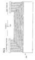
- FIG. 8 shows a capacitor arrangement 600, which also contains nine electrodes.
- the capacitor arrangement 600 is asymmetrically structured such that only electrodes S1, S3, S5, S7 and S9 can be contacted at the steps of the left side, ie only every second electrode.
- the electrodes S2, S4, S6 and S8 can be contacted.
- the method steps for producing the capacitor arrangement 600 are similar to those in the production of the capacitor arrangement 500.
- the depth of focus is 1 ⁇ m.
- the lower electrode of the capacitor arrangement lies above the lower metallization layer in relation to the two metallization layers, between which the capacitor arrangement is arranged.
- the lower electrode of the capacitor assembly is already formed in the metallization layer, e.g. by a damascene process followed by a polishing step.
- the other electrodes of the capacitor arrangement are then produced.
- the lower electrode of the capacitor arrangement is connected in alternative embodiments via at least one metallization layer lying deeper than this electrode.
- FIG. 9 shows a capacitor arrangement 700, which contains four metallization layers Me1 to Me4 above a semiconductor substrate, not shown.
- Each metallization layer Me1 to Me4 contains a plurality of aluminum alloy interconnects with an addition of copper of less than 2%.
- FIG. 9 however, only the interconnects of the metallization layers are Me1 to Me4, which belong to the capacitor arrangement 700. Interconnects for connecting active components in the semiconductor substrate are therefore not shown.
- the metallization layers Me1 to Me4 are electrically insulated from one another in this order by means of interlayers ILD1 to ILD3, for example silicon dioxide.
- interlayers ILD1 to ILD3 for example silicon dioxide.
- the metallization layers Me1 to Me4 each have a thickness of 500 nm.
- the spacings of adjacent metallization layers Me1 to Me4 are, for example, at 800 nm in each case.
- a lower electrode 710 is located in the metallization layer Me1. Between the electrode 710 and an overlying partial electrode 712 is a dielectric 714.
- the partial electrode 712 is formed by a 45 nm thick titanium nitride layer.
- the dielectric 714 is a 45 nm thick silicon nitride layer.
- the electrodes of the capacitor arrangement 700 have a rectangular base area, wherein a length L lies in the longitudinal direction of the rectangles.
- the length L of the partial electrode 712 is for example 150 ⁇ m.
- the lower electrode 710 and the dielectric 714 protrude beyond the sub-electrode 712.
- the dielectric 714 served as an etching stop in the patterning of the partial electrode 712 and was only slightly etched, so that the illustration in FIG FIG. 9 is exaggerated.
- the lower electrode 710 extends further beyond the partial electrode 712 than on the right side. This results in a connection area for a contact section Via1, which lies between a conductive track 718 of the metallization layer Me2 and the electrode 710.
- the contact section Via1 is part of a Row of contact sections between a conductive track 718 in the metallization Me2 and the base electrode 710th
- a partial electrode 720 connected to the partial electrode 712 via contact sections Via2 and Via3 likewise lies in the metallization layer Me2.
- the contact sections Via2 and Via3 are part of two rows between the sub-electrodes 712 and 720.
- the sub-electrodes 712 and 720 form a center electrode of the capacitor arrangement 700.
- a partial electrode 722 Adjacent to the partial electrode 720 in the intermediate layer ILD2 is a partial electrode 722, which is separated from the partial electrode 720 by a dielectric 724.
- the partial electrode 722 consists of a 45 nm thick titanium nitride layer.
- the dielectric 724 again consists of a 45 nm thick silicon nitride layer.
- the partial electrode 722 also has the length L.
- the partial electrode 720 and the dielectric 724 project beyond the partial electrode 722 on the right and left. Also, the dielectric 724 served as an etch stop in generating the partial electrode 722 and was only slightly attacked. As a result of these measures, the dielectric 724 is not damaged on the sensitive edge region of the electrode 722.
- the partial electrode 720 protrudes more strongly beyond the partial electrode 722 than on the left side, so that a contact area for a contact section Via4 arises, which extends between the partial electrode 720 and a conductive track 728 in the metallization layer Me3.
- the contact section Via4 is also part of a series of contact sections between the conductive track 728 and the partial electrode 720.
- a partial electrode 730 which forms the second center electrode of the capacitor arrangement 700 together with the partial electrode 722, lies in the metallization layer Me3.
- the sub-electrodes 722 and 730 are interconnected via two via rows, of which in FIG. 9 two contact sections Via5 and Via6 are shown.
- the sub-electrode 730 is separated from the conductive line 728 by parts of the interlayer ILD3, see gap 731.
- the upper center electrode of the sub-electrodes 722 and 730 is electrically connected to the lower electrode 710 via two superimposed rows of contact portions.
- the upper row leads from the partial electrode 730 to the conductive track 718 FIG. 9 a contact section Via7 of this series of contact sections is shown. To the lower row belongs the contact section Via1.
- the capacitor arrangement 700 also contains an upper electrode 732, which is separated from the partial electrode 730 by a dielectric 734.
- the partial electrode 732 is also made of titanium nitride and has a thickness of 45 nm.
- the dielectric 734 is made of silicon nitride and has a thickness of 45 nm.
- the dielectric 734 was used as an etch stop and only slightly etched, cf. exaggerated representation in FIG. 9 ,
- the partial electrode 730 protrudes beyond the upper electrode 732 on the left and right together with the dielectric 734. At the left edge, the partial electrode 730 projects more strongly beyond the upper electrode 732 than at the right edge, so that a connection possibility for the row of contact sections is formed, to which also the contact section Via7 belongs.
- Top electrode 732 is also of length L. All electrodes 732, 722, and 712 in shims ILD3, ILD2, and ILD1, respectively, are aligned one above the other, as shown in dashed lines 736 and 738, and have similar contours.
- the upper electrode 732 is connected by two rows of contact portions to a conductive track 740 located in the metallization layer Me4. In FIG. 9 two contact sections Via8 and Via9 of these two rows are shown. From the right-hand part of the interconnect 740, a number of contact sections extend to the interconnect 728, see contact section Via10. Thus, the upper electrode 732 is electrically connected to the lower center electrode, ie, the sub-electrodes 712 and 720 of the capacitor array 700.
- the left parts of the conductive track 740 and the partial electrode 730 serve to connect the capacitor arrangement, so that a total capacitance Cges is created between these parts.
- FIG. 9 a circuit diagram 750 is shown, from which the interconnection of capacitances C1, C2 and C3 of the capacitor arrangement 700 can be seen.
- the capacitance C1 is formed by the lower electrode 710 and by the partial electrode 712.
- the capacitance C2 is formed by the partial electrode 720 and the partial electrode 722.
- the capacitance C3 is formed by the partial electrode 730 and the upper electrode 732.
- the capacitances C1 to C3 are electrically connected in parallel to one another, which is achieved by the toothed arrangement of the electrodes in the capacitor arrangement 700.
- the capacitor array 700 includes only two MIM capacitors so that, for example, only the metallization layers Me1 to Me3 are included in the capacitor array.
- the area capacitance is not tripled, but only doubled, see dashed line 752 in the circuit diagram 750.
- the capacitor arrangement only contains the capacitances C1 and C2.
- the capacitor arrangement extends over more than four metallization levels. In this way, a quadruple, a fivefold, etc. of the area capacity can be achieved.
- the metallization layer Me4 would be structured like the metallization layer Me2. Above the metallization layer Me4 there would be a metallization layer Me5, which would be structured like the metallization layer Me3.
- contact portions Via1, Via7, etc. would be superposed with each other, to which the lower electrode 710, the second center electrode, the fourth center electrode, etc. are connected.
- the structures of the electrodes in the capacitor arrangement are repeated.
- identical subsections of masks can be used for lithography.
- all the electrodes 712, 722, 732 are made in intermediate layers ILD1 to ILD3 according to the same layout.
- the lower electrode 820 and the partial electrode 828 are located in the metallization layer 802 or 804 and consist in the exemplary embodiment of an aluminum alloy with less than 5% additions of copper and / or silicon.
- the metallization layers 802 to 806 are 500 nm thick. The distance between adjacent metallization layers is in the exemplary embodiment 750 nm.
- the electrodes 822, 824, the sub-electrode 826, the electrodes 830, 832 and the sub-electrode 834 are made of titanium nitride, each having a thickness of 45 nm.
- Dielectrics 840 to 852 are located in this order between the electrodes 820 to 834.
- a dielectric 854 is also located on the upper electrode 824.
- the dielectrics 840 to 854 are made of silicon nitride and have a layer thickness of 45 nm in the exemplary embodiment.
- the dielectric 846 is located on the partial electrode 826.
- each second electrode of the capacitor array 800 begins from the lower electrode 820.
- Three right hand contact sections Via15 to Via17 and a conductive trace 864 in the metallization layer 804 electrically connect the electrodes 822, an electrode made up of the subelectrodes 826 and 828 and the electrode 832, i.
- Each second electrode of the capacitor arrangement begins with the electrode 822 adjacent to the lower electrode 820.
- the contact sections Via11 to Via17 are each part of a series of contact sections that extend into the leaf plane respectively out of the leaf plane.
- the electrode 822, the dielectric 842, the electrode 824, the dielectric 844, the sub-electrode 826 and the dielectric 846 form a layer stack 870.
- the layers of the layer stack 870 are deposited successively and subsequently by means of only two lithography processes structured. With a first lithography process, the electrode 824 and the dielectric 844 are patterned, and the partial electrode 826 and the dielectric 846 are pre-structured. With the second lithography process, the electrode 822 and the dielectric 842 are patterned. In addition, the sub-electrode 826 and the dielectric 846 are patterned using the second lithography process. A third lithography process is needed to pattern the electrode 828 and thus also the dielectric 848.
- the intermediate layer 812 is produced and planarized. Subsequently, vial holes for the contact sections Via11, Via12 and Via15 as well as for contact sections Via18 and Via19 are etched and filled. The contact sections Via18 and Via19 lead to the partial electrode 826 and are part of two mutually parallel rows of contact sections.
- a layer stack 872 is formed that includes layers for the electrode 830, for the dielectric 850, for the electrode 832, for the dielectric 852, for the top electrode 834, and for the dielectric 854.
- the layer stack 872 is also patterned by the same method as the layer stack 870. Another lithography method is required to pattern the electrode 828 and thus also the dielectric 848.
- the material of the intermediate layer 814 is deposited.
- contact holes are produced for the contact sections Via13, Via14, Via16 and Via17 and for two contact sections Via20 and Via21.
- the contact sections Via20 and Via21 lie in the finished capacitor arrangement 800 between the conductor track 862 and the upper electrode 854.
- the contact sections Via20 and Via21 are also components of two rows of contact sections between the conductive track 862 and the upper electrode 854.
- a circuit diagram 880 shows the interconnection of capacitances C1a to C6a of the circuit arrangement 800.
- the area capacitance is multiplied sixfold by the arrangement of the capacitances C1a to C6a.
- the sub-electrode 826 and the sub-electrode 834 are aligned.
- the electrodes 824 and the dielectric 844 are not present in the layer stack 870, see curly bracket 881a. Also, the electrode 830 and the dielectric 850 are not included in the layer stack 872, see curly bracket 881b.
- the contact sections Via12 and Via14 omitted.
- the conductor track 860 is electrically conductively connected to the sub-electrode 828.
- the right part of the sub-electrode 828 is designed as a separate interconnect and connected to the contact portions Via15 and Via17.
- the contact section Via15 serves to connect the electrode 824 extended to the right.
- copper metallization layers are used in capacitor arrays 700 and 800 rather than aluminum metallization layers.
- a so-called damascene method is used in this case, which ends in each case with a chemical-mechanical polishing step.
- tantalum nitride is used instead of the titanium nitride.
- TiN or TaN liners are used as intermediaries between the electrodes and the dielectric, for example to reduce roughness or increase adhesion.
- the illustrated capacitor arrangements are deposited in design libraries as standard components for the chip designer. This allows the designer to choose between single MIM capacitors, dual capacitors, triple capacitors, etc., or between capacitor arrays spanning multiple metallization layers, and in turn multiple single, dual or triple MIM capacitors, etc., or a combination contained from these capacitors.
- measures are also taken in the capacitor arrangements 700 and 800 to avoid damage to the edge of the dielectric, for example the use of a supernatant and / or the combination of dry etching and wet etching or wet cleaning.
- sets of capacitor arrays 700 and 800, respectively, are made in which certain contact portions are omitted to reduce the overall capacitance.
- the contact section Via11 is omitted, so that the capacitance C1a no longer contributes to the total capacitance C.
- Figure 11A shows an integrated circuit arrangement 1100, which includes a semiconductor wafer, not shown, for example.
- a silicon wafer wafer
- In or on the semiconductor wafer are active areas of a variety of electronic components, such as transistors.
- a dielectric layer ILD is optionally applied after the deposition of further layers, which in the exemplary embodiment lies between two metallization layers.
- the upper of these two metallization layers is formed in a titanium nitride layer 1102 which has been deposited on the dielectric layer ILD.
- the titanium nitride layer 1102 has a thickness D1 of 45 nm in the exemplary embodiment.
- a silicon nitride layer 1104 is applied as a dielectric layer having a thickness D2 of, for example, 100 nm. Subsequently, on the silicon nitride layer 1104, a further titanium nitride layer 1106 is applied, which has a thickness D3 of 45 nm.
- a photoresist layer 1110 is deposited. Subsequently, the photoresist layer 1110 is exposed by means of a mask. After exposure, the photoresist layer 1110 is developed to form a photoresist region 1112.
- a plasma etching process is performed, in which the titanium nitride layer 1106 is patterned.
- a cover electrode 1120 of the capacitor arrangement to be generated is formed below the photoresist area 1112.
- the thickness of the cover electrode 1120 is equal to the thickness D3, ie 45 nm.
- the titanium nitride layer is almost completely removed.
- the residues 1122 and 1124 have, for example, only a thickness of 1 nm or 2 nm.
- the titanium nitride layer 1106 is time-etched during plasma etching so that the thickness of the dielectric layer 1104 remains substantially unchanged.
- the etch removal on the dielectric layer 1104 caused by the dry etching is below 1 nm.
- the aim is a dry etching of the titanium nitride layer 1106 without overetching or an overetching of 0 s (seconds). This means that only material of the titanium nitride layer 1106 is to be removed, but no material of the dielectric layer 1104. Therefore, when calculating the etching time, the thinnest points of the titanium nitride layer 1106 must be assumed.
- the remaining remnants of the photoresist layer 1110 are removed again.
- the photoresist area 1112 is removed.
- a wet cleaning step is performed in which residues 1122 and 1124 are removed.
- the wet cleaning is highly selective to the silicon nitride of the silicon nitride layer 1104, so that the thickness of the silicon nitride layer 1104 decreases only slightly to a thickness D2a.
- a wet-chemical etching bath As a wet-chemical etching bath, a mixture of a 35% aqueous hydrogen peroxide solution and an approximately 28% aqueous ammonia solution is used. The volume ratio of hydrogen peroxide solution to ammonia solution is 20: 1. The wet-chemical etching is carried out at room temperature.
- Such etching of titanium nitride is highly selective to silicon nitride.
- there is a slight edge etching of the electrode 1120 which however is not disturbing if the electrode 1120 has previously been structured slightly larger than actually required.
- a photoresist layer 1130 is then deposited, exposed and developed according to a predetermined mask, a photoresist region 1132 being formed above a portion B1 of a region of the silicon nitride layer 1104 not covered by the cover electrode 1120 and above the cover electrode 1120.
- the silicon nitride layer 1104 and the underlying titanium nitride layer 1102 are patterned according to the photoresist region 1132.
- conductive tracks are produced in the titanium nitride layer 1102, which serve to connect the active components.
- a dielectric layer 1140 which consists, for example, of silicon dioxide and has a thickness of several hundred nanometers, is applied to the capacitor arrangement 1136.
- the dielectric layer 1140 is planarized and forms the dielectric to the next higher metallization layer, i. a metallization layer farther from the semiconductor substrate than the metallization layer formed from the titanium nitride layer 1102.
- contact portion holes 1142 and 1144 for contact portion are produced by means of another lithography process, i. for so-called vias.
- contact portion hole 1142 through the dielectric layers 1140 and 1104 to the bottom electrode 1134 and in the case of the contact hole 1144 only through the dielectric layer 1140 to the top electrode 1120 is etched.
- the contact portion holes 1142 and 1144 are then optionally filled with the introduction of suitable intermediate layers with an electrically conductive material, for example. With tungsten. Of the right edge of the contact hole 1142 has a distance A from the left edge of the cover electrode 1120 of, for example, 400 nm.
- dielectric double or multiple layers are used in place of the dielectric layer 1104.
- dielectric layers 1104. instead of the titanium nitride layers 1102 and 1106, double or multiple layers of electrically conductive materials are also used.
- the explained methods at the boundary between the upper layer stack of electrically conductive layers and a layer stack of dielectric layers remain as described above with reference to FIGS FIGS. 11A to 11D explained.
- the dielectric layer 1104 is not penetrated by a contact portion, for example, when the bottom electrode is in a metallization layer and connected from below. Nevertheless, the dielectric of the capacitor and the bottom electrode are beyond the cover electrode in order to avoid damage to the dielectric when structuring the dielectric layer and the bottom electrode in sensitive edge regions of the cover electrode.
- the supernatant dielectric is neither appreciably etched by the procedure outlined above, nor does it leave residues of the layer used for the production of the cover electrode on the dielectric. In particular, there are no residues on the edge of the electrode in areas where the top electrode has been patterned by the dry etching process.
- the lower electrode is contacted only on a lateral side of the capacitor.
- a via penetrates the dielectric.
- the dielectric and the bottom electrode protrude beyond the cover electrode without a via being attached there. Thus damage to the dielectric at the sensitive electrode edge region is also avoided on this side.
- FIGS. 11A to 11D The on hand of the FIGS. 11A to 11D The described methods are also used in capacitors which contain a plurality of dielectric layers between three or more than three electrodes, in particular in capacitor arrangements which lie between two metallization layers or extend over a plurality of metallization layers.
Abstract
Description
Die Erfindung betrifft zum Herstellen einer Kondensatoranordnung ein Verfahren, bei dem ein Schichtstapel erzeugt wird. Der Schichtstapel enthält in der folgenden Reihenfolge:
- eine Grundelektrodenschicht für eine Grundelektrode,
- ein Grunddielektrikum, und
- eine Deckelektrodenschicht für eine Deckelektrode.
- a base electrode layer for a base electrode,
- a base dielectric, and
- a top electrode layer for a top electrode.
Solche Kondensatoren werden in integrierten Schaltungsanordnungen auch als MIM-Kondensatoren bezeichnet (Metall-Isolator-Metall), wobei die Elektrodenschichten bzw. die Elektroden nicht zwingend aus einem Metall oder aus einer Metalllegierung hergestellt sein müssen. So gibt es beispielsweise auch Elektroden aus dotiertem Polysilizium. Die Elektroden haben üblicherweise einen spezifischen Widerstand kleiner als 10-3 Ωcm. Zwischen den Elektroden wird ein Dielektrikum angeordnet, das üblicherweise einen spezifischen elektrischen Widerstand hat, der größer als 1012 Ωcm ist.Such capacitors are referred to in integrated circuit arrangements as MIM capacitors (metal-insulator metal), wherein the electrode layers or the electrodes need not necessarily be made of a metal or a metal alloy. For example, there are electrodes made of doped polysilicon. The electrodes usually have a resistivity of less than 10 -3 Ωcm. Between the electrodes, a dielectric is arranged, which usually has a specific electrical resistance which is greater than 10 12 Ωcm.
Für viele Anwendungen bestehen besondere Anforderungen hinsichtlich der Linearität und der Güte der Kondensatoren in den integrierten Schaltkreisen. Auch soll die Herstellung des integrierten Kondensators möglichst einfach sein.For many applications, there are special requirements in terms of linearity and the quality of the capacitors in the integrated circuits. Also, the production of the integrated capacitor should be as simple as possible.
Weiterhin soll die Flächenkapazität pro benötigter Chipfläche möglichst groß sein. Aus dem Fachaufsatz "
Es ist Aufgabe der Erfindung, zum Herstellen einer Kondensatoranordnung ein einfaches Verfahren anzugeben, mit dem sich insbesondere Kondensatoranordnungen herstellen lassen, die eine hohe Güte und eine hohe Linearität und/oder eine große Flächenkapazität haben. Außerdem soll eine Kondensatoranordnung mit diesen Eigenschaften angegeben werden.It is an object of the invention to provide a simple method for producing a capacitor arrangement with which In particular, it is possible to produce capacitor arrangements which have a high quality and a high linearity and / or a large area capacity. In addition, a capacitor arrangement with these properties should be specified.
Die auf das Verfahren bezogene Aufgabe wird durch das im Patentanspruch 1 angegebene Verfahren gelöst. Weiterbildungen sind in den Unteransprüchen angegeben.The object related to the method is achieved by the method specified in
Die Erfindung geht von der Überlegung aus, dass es das Ziel der Technologieentwicklung ist, eine möglichst hohe Kapazität pro Flächeneinheit bereitzustellen. Dies lässt sich beispielsweise dadurch erreichen, dass Dielektrika ausgewählt werden, deren Dielektrizitätskonstante möglichst groß sind. Eine minimale zulässige Dicke und damit auch die maximale Flächenkapazität wird jedoch durch die Produktanforderung an Lebensdauer und Spannungsfestigkeit bestimmt. Beispielsweise erzielt man bei einer Dicke von ca. 45 nm Siliziumnitrid SiN eine Kapazität von ca. 1.30 fF/µm2 (Femtofarad je Quadratmikrometer) bei einer Lebensdauer von 15 Jahren, 2,3 mm2 Gesamtfläche im Produkt und einer Betriebsspannung von 3,6 V. Eine weitere Reduzierung der Dicke würde zu Produktausfällen innerhalb der zugrundegelegten 15 Jahre führen und ist somit nicht möglich. Höhere Gesamtkapazitäten führen zu weiteren Flächenanforderungen im Produkt und damit zu höheren Chipkosten.The invention is based on the consideration that the goal of technology development is to provide the highest possible capacity per unit area. This can be achieved, for example, by selecting dielectrics whose dielectric constants are as large as possible. However, a minimum permissible thickness and thus also the maximum area capacity is determined by the product requirement for service life and dielectric strength. For example, with a thickness of approximately 45 nm silicon nitride SiN, a capacitance of approximately 1.30 fF / μm 2 (femtofarad per square micrometer) is achieved with a service life of 15 years, a total surface area of 2.3 mm 2 in the product and an operating voltage of 3.6 V. A further reduction in thickness would lead to product failures within the underlying 15 years and is therefore not possible. Higher total capacities lead to further space requirements in the product and thus to higher chip costs.
Andererseits geht die Erfindung von der Überlegung aus, dass einer Erhöhung der Anzahl der Elektroden, die zwischen zwei Metallisierungslagen angeordnet sind, der Aufwand für die Strukturierung jeder einzelnen Elektroden entgegensteht. Dieser Aufwand steigt ohne zusätzliche Maßnahmen linear zur Anzahl der Elektroden.On the other hand, the invention is based on the consideration that an increase in the number of electrodes, which are arranged between two metallization layers, precludes the effort for the structuring of each individual electrode. This effort increases without additional measures linear to the number of electrodes.
Deshalb werden beim erfindungsgemäßen Verfahren zusätzlich zu den eingangs genannten Verfahrensschritten zwischen der Grunddielektrikumschicht und der Deckelektrodenschicht mindestens eine Mittelelektrodenschicht und eine Deckdielektrikumschicht angeordnet. Die Deckelektrodenschicht und die Mittelelektrodenschicht werden mit einem ersten Lithografieverfahren strukturiert. Anschließend werden die vorstrukturierte Deckelektrodenschicht und die Grundelektrodenschicht mit einem zweiten Lithografieverfahren strukturiert.For this reason, in the method according to the invention, at least in addition to the above-mentioned method steps between the base dielectric layer and the top electrode layer a center electrode layer and a cover dielectric layer are arranged. The top electrode layer and the center electrode layer are patterned by a first lithography method. Subsequently, the prestructured cover electrode layer and the base electrode layer are patterned by a second lithography method.
Damit werden beim erfindungsgemäßen Verfahren für drei Elektroden nur zwei Lithografieverfahren benötigt. Die lineare Abhängigkeit von Anzahl der Elektroden zur Anzahl der für die Strukturierung der Kondensatoranordnung benötigten Lithografieverfahren ist damit durchbrochen. Damit wird die Anzahl der Lithografie- und Ätzschritte im Prozess deutlich reduziert. Dieser Effekt wird um so deutlicher, je mehr Elektroden übereinander für eine Kondensatoranordnung gestapelt werden.Thus, only two lithography processes are required in the method according to the invention for three electrodes. The linear dependence of the number of electrodes on the number of lithography processes required for structuring the capacitor arrangement is thus broken. This significantly reduces the number of lithography and etching steps in the process. This effect becomes all the clearer the more electrodes are stacked on top of each other for a capacitor arrangement.
Die Grundidee des erfindungsgemäßen Verfahrens besteht darin, zuerst einen Schichtstapel mit Elektrodenschichten für die benötigten Elektroden zu erzeugen. Danach wird im ersten Lithografieverfahren ein oberer Teil des Schichtstapels strukturiert, beispielsweise die beiden oberen Elektrodenschichten oder ein oberer Schichtstapel aus mehr als zwei Elektrodenschichten. In dem zweiten Lithografieverfahren werden dann gleichzeitig sowohl Elektrodenschichten in dem oberen Schichtstapel, d.h. Elektrodenschichten, die bereits mit Hilfe des ersten Lithografieverfahrens strukturiert worden sind, als auch Elektrodenschichten strukturiert, die mit Hilfe des ersten Lithografieverfahrens noch nicht strukturiert worden sind.The basic idea of the method according to the invention is first to produce a layer stack with electrode layers for the required electrodes. After that, in the first lithographic process, an upper part of the layer stack is structured, for example the two upper electrode layers or an upper layer stack comprising more than two electrode layers. In the second lithographic process, both electrode layers in the upper layer stack, i. Electrode layers that have already been patterned using the first lithography process, as well as structured electrode layers that have not yet been structured using the first lithography process.
Bei einer Weiterbildung des erfindungsgemäßen Verfahrens wird zwischen der Grunddielektrikumschicht und der Deckelektrodenschicht ein Stapel mit mindestens zwei Mittelelektrodenschichten erzeugt. Nach dem Erzeugen einer Mittelelektrodenschicht und vor dem Erzeugen der nächsten Mittelelektrodenschicht wird jeweils eine Mitteldielektrikumschicht erzeugt, die zwischen zwei benachbarten Mittelelektrodenschichten liegt. Im einfachsten Fall der Weiterbildung enthält die Kondensatoranordnung damit mindestens vier Elektroden. Jede Mittelelektrode wird für Kapazitäten oberhalb bzw. unterhalb der Mittelelektrode genutzt. Bei der Verwendung von fünf Elektroden verdoppelt sich beispielsweise die Kapazität der Anordnung im Vergleich zu einer Anordnung mit drei Elektroden, die ihrerseits im Vergleich zu einer Anordnung mit zwei Elektroden eine doppelt so hohe Kapazität bzw. flächenbezogene Kapazität hat. Zum Herstellen einer Kondensatoranordnung mit fünf Elektroden sind beispielsweise nur drei Lithografieverfahren erforderlich.In a development of the method according to the invention, a stack with at least two center electrode layers is produced between the base dielectric layer and the top electrode layer. After generating a center electrode layer and before generating the next center electrode layer, a center dielectric layer is generated in each case, which lies between two adjacent central electrode layers. In the simplest case of the development, the capacitor arrangement thus contains at least four electrodes. Each center electrode is used for capacities above and below the center electrode. For example, using five electrodes doubles the capacitance of the array as compared to a three-electrode array which, in turn, has twice the capacitance as compared to a two-electrode array. For example, only three lithography processes are required to fabricate a five electrode capacitor array.
Bei einer nächsten Weiterbildung des erfindungsgemäßen Verfahrens wird beim ersten Lithografieverfahren gemeinsam mit der Deckelektrodenschicht mindestens eine zwischen der Deck-elektrodenschicht und der Mittelelektrodenschicht angeordnete Elektrodenschicht strukturiert. Außerdem wird beim ersten Lithografieverfahren gemeinsam mit der Mittelelektrodenschicht mindestens eine zwischen der Mittelelektrodenschicht und der Grundelektrodenschicht angeordnete Elektrodenschicht strukturiert, beispielsweise eine der Mittelelektrodenschicht benachbarte Elektrodenschicht. Die Grundelektrodenschicht selbst wird jedoch beim ersten Lithografieverfahren nicht strukturiert.In a next development of the method according to the invention, in the first lithography method, at least one electrode layer arranged between the cover electrode layer and the middle electrode layer is patterned together with the cover electrode layer. In addition, in the first lithography method, at least one electrode layer arranged between the center electrode layer and the base electrode layer is patterned together with the center electrode layer, for example, an electrode layer adjacent to the center electrode layer. However, the base electrode layer itself is not patterned in the first lithography process.
Bei der Weiterbildung werden beim zweiten Lithografieverfahren die Deckelektrodenschicht und die zwischen der Deckelektrodenschicht und der Mittelelektrodenschicht angeordnete Elektrodenschicht strukturiert. Ebenfalls beim zweiten Lithografieverfahren werden die Grundelektrodenschicht und mindestens eine zwischen der Grundelektrodenschicht und der Mittelelektrode angeordnete Elektrodenschicht strukturiert. Die außer der Grundelektrodenschicht strukturierte Elektrodenschicht wurde dabei im ersten Lithografieverfahren ebenfalls nicht strukturiert.In the development, in the second lithography method, the cover electrode layer and the electrode layer arranged between the cover electrode layer and the center electrode layer are patterned. Also in the second lithography method, the base electrode layer and at least one electrode layer arranged between the base electrode layer and the center electrode are patterned. The structured electrode layer except the base electrode layer was also not structured in the first lithography process.
Bei dieser Weiterbildung enthält die Kondensatoranordnung mindestens sechs Elektroden. Zum Strukturieren von sechs Elektroden mit jeweils von den anderen Elektroden verschiedenen Elektrodenformen sind nur drei Lithografieverfahren erforderlich. Jedoch kann nach dem gleichen Verfahren auch eine Kondensatoranordnung erzeugt werden, die noch mehr Elektroden enthält, beispielsweise neun Elektroden. Im Fall von neun Elektroden sind zur individuellen Strukturierung jeder Elektrode nur vier Lithografieverfahren erforderlich.In this development, the capacitor arrangement contains at least six electrodes. For structuring six electrodes each having different electrode shapes from the other electrodes, only three lithography methods are required. However, according to the same method, it is also possible to produce a capacitor arrangement which contains even more electrodes, for example nine electrodes. In the case of nine electrodes, only four lithography techniques are required to individually pattern each electrode.
Bei einer nächsten Weiterbildung wird nach den ersten beiden Lithografieverfahren mindestens einmal ein drittes Lithografieverfahren ausgeführt, bei dem mindestens zwei nicht benachbarte Elektrodenschichten des Schichtstapels strukturiert werden. Die zwischen den in dem dritten Lithografieverfahren strukturierten Elektrodenschichten liegenden Elektrodenschichten werden in dem dritten Lithografieverfahren jedoch nicht strukturiert. Durch diese Maßnahmen lassen sich Abstufungen weiter verfeinern, die mit den beiden ersten Lithografieverfahren erzeugt worden sind.In a next development, after the first two lithography processes, a third lithography process is carried out at least once in which at least two nonadjacent electrode layers of the layer stack are patterned. However, the electrode layers lying between the electrode layers structured in the third lithography method are not patterned in the third lithography method. These measures further refine gradations produced by the first two lithographic processes.
Bei einer nächsten Weiterbildung des erfindungsgemäßen Verfahrens wird beim Durchführen der Lithografieverfahren die Ätzung auf mindestens einer Dielektrikumschicht gestoppt, die unter der in diesem Lithografieverfahrens zuletzt geätzten Elektrodenschicht liegt. Die gesamte Ätzung wird bei einer Ausgestaltung trocken-chemisch oder chemisch-physikalisch durchgeführt, z.B. mit einem Plasmaverfahren oder einem RIE-Verfahren (Reactive Ion Etching). Durch diese Maßnahme wird erreicht, dass das Dielektrikum im Bereich des Elektrodenrandes nicht übermäßig geschädigt wird. Besonders im Elektrodenrandbereich führen Beschädigungen des Dielektrikums zu erheblichen Einschränkungen bei der Linearität und der Güte der Kondensatoranordnung. Beispielsweise sind an diesen Bereichen Spannungsüberschläge möglich.In a next development of the method according to the invention, when carrying out the lithography method, the etching is stopped on at least one dielectric layer, which is below the last electrode layer etched in this lithography method. In one embodiment, the entire etching is carried out dry-chemically or chemically-physically, for example using a plasma method or an RIE method (Reactive Ion Etching). By this measure it is achieved that the dielectric in the region of the electrode edge is not excessively damaged. Damage to the dielectric, in particular in the electrode edge region, leads to considerable limitations in the linearity and the quality of the capacitor arrangement. For example, voltage flashovers are possible at these areas.
Bei einer alternativen Weiterbildung wird beim Durchführen eines Lithografieverfahrens die Ätzung in der in diesem Lithografieverfahren zuletzt geätzten Elektrode gestoppt. Der verbleibende Teil dieser Elektrode wird nass-chemisch geätzt. Beim nass-chemischen Ätzen wird das Dielektrikum nicht so stark angegriffen, wie beim trocken-chemischen Ätzen.In an alternative development, the etching in the last electrode etched in this lithography process is stopped when carrying out a lithography process. The remaining part of this electrode is wet chemically etched. In wet-chemical etching, the dielectric is not attacked as strongly as in the dry-chemical etching.
Bei einer nächsten Weiterbildung des erfindungsgemäßen Verfahrens werden angeätzte bzw. als Ätzstopp dienende Bereiche von Dielektrikumschichten in der Nähe einer in einem Lithografieverfahren zuletzt strukturierten Elektrode im nächsten und auch im folgenden Lithografieverfahren mit einem Resist bedeckt, so dass das Dielektrikum in diesen Bereichen nicht weiter geschädigt wird. Elektrodenschichtrandbereiche, die in der Nähe eines in einem Lithografieverfahren durchätzten Dielektrikums liegen, werden in einem folgenden Lithografieverfahren entfernt. Damit hat das geschädigte Dielektrikum für die Kondensatoranordnung keine elektrische Funktionen mehr.In a next development of the method according to the invention, etched or etch stop regions of dielectric layers in the vicinity of an electrode last patterned in a lithography process are covered with a resist in the next and also in the following lithography process, so that the dielectric is not further damaged in these regions , Electrode layer edge regions that lie in the vicinity of a dielectric etched through in a lithography process are removed in a subsequent lithography process. Thus, the damaged dielectric for the capacitor arrangement no longer has electrical functions.
Bei einer nächsten Weiterbildung ist der Schichtstapel der Kondensatoranordnung frei von in Stapelrichtung, d.h. in Normalenrichtung zur Waferoberfläche, fluchtenden Elektrodenkanten. Durch diese Maßnahme wird erreicht, dass an den Au-ßenkanten der Elektroden keine durchgeätzten Dielektrikumschichten liegen.In a next development, the layer stack of the capacitor arrangement is free from in the stacking direction, i. in the normal direction to the wafer surface, aligned electrode edges. This measure ensures that no etched-through dielectric layers are located on the outer edges of the electrodes.
Bei einer anderen Weiterbildung des erfindungsgemäßen Verfahrens werden die Elektrodenanschlüsse jeder zweiten Elektrode auf einer Stapelseite angeordnet. Die Elektrodenanschlüsse der anderen Elektroden werden dagegen auf einer anderen Stapelseite angeordnet. Durch diese Maßnahme ergibt sich eine sehr einfache Verdrahtung der Kondensatoranordnung in einer Metallisierungsebene ohne zu stark verzweigte Leitbahnstrukturen.In another development of the method according to the invention, the electrode terminals of each second electrode are arranged on a stack side. On the other hand, the electrode terminals of the other electrodes are arranged on another stack side. This measure results in a very simple wiring of the capacitor arrangement in a metallization without too much branched Leitbahnstrukturen.
Bei einer nächsten Weiterbildung werden die Elektroden des Schichtstapels mit gleicher Schichtdicke hergestellt. Dies führt zu einer geringen Höhe des Schichtstapels im Vergleich zu unterschiedlich dicken Schichten innerhalb eines Schichtstapels.In a next development, the electrodes of the layer stack are produced with the same layer thickness. This leads to a low height of the layer stack compared to different thickness layers within a layer stack.
Bei einer alternativen Weiterbildung wird dagegen eine früher als eine andere Elektrode strukturierte Elektrode dicker ausgeführt als die andere Elektrode. Die dickere Elektrode ist vorzugsweise die Deckelektrode. Das Verwenden von Elektroden unterschiedlicher Dicke ermöglicht es, die Prozessfenster beim dem Strukturieren des Schichtstapels zu vergrößern.In an alternative development, on the other hand, an electrode structured earlier than another electrode is made thicker than the other electrode. The thicker electrode is preferably the cover electrode. The use of electrodes of different thickness makes it possible to increase the process window when structuring the layer stack.
Bei einer nächsten Weiterbildung sind Elektrodenanschlüsse an mindestens einer Seite, an mindestens zwei Seiten, an mindestens drei Seiten oder an mindestens vier Seiten einer Elektrode aufgereiht. Durch diese Maßnahme lassen sich Anschlusswiderstände verringern. Dies führt zu einer hohen Güte der Kondensatoranordnung.In a next development electrode connections are lined up on at least one side, on at least two sides, on at least three sides or on at least four sides of an electrode. This measure can reduce connection resistance. This leads to a high quality of the capacitor arrangement.
Bei einer nächsten Weiterbildung wird eine Elektrodenschicht in mehrere Teilelektroden strukturiert, vorzugsweise die Deckelektrodenschicht. Die Teilelektroden werden so angeschlossen, dass sie sich zum Vergrößern der Kapazität der Kondensatoranordnung zusammenschalten lassen. Solche sogenannten Modellierungskapazitäten könnten beispielsweise in Dual- oder Tripelband-Mobilfunkschaltkreisen eingesetzt werden.In a next development, an electrode layer is structured into a plurality of sub-electrodes, preferably the cover electrode layer. The sub-electrodes are connected so that they can be connected together to increase the capacitance of the capacitor arrangement. Such so-called modeling capabilities could be used, for example, in dual or triple band mobile radio circuits.
Die Erfindung betrifft außerdem eine Kondensatoranordnung, die in der folgenden Reihenfolge enthält:
- eine Grundelektrode,
- ein Grunddielektrikum,
- mindestens zwei Mittelelektroden,
- ein Deckdielektrikum, und
- eine Deckelektrode.
- a base electrode,
- a basic dielectric,
- at least two center electrodes,
- a deck dielectric, and
- a cover electrode.
Bei einer Weiterbildung enthält die Kondensatoranordnung drei Mittelelektroden, fünf Mittelelektroden oder sieben Mittelelektroden usw. Für die Kondensatoranordnung und ihre Weiterbildung gelten die für das erfindungsgemäße Verfahren genannten Wirkungen ebenfalls.In a further development, the capacitor arrangement contains three center electrodes, five center electrodes or seven center electrodes, etc. For the capacitor arrangement and its development, the effects mentioned for the method according to the invention also apply.
Die Kondensatoranordnung lässt sich zur Anpassung der Zielkapazität in Hochfrequenzprodukten nutzen. Beispielsweise werden sie für GSM- (Global System for Mobile Communication) oder in UMTS-Anwendungen (Universal Mobile Telecommunication System), insbesondere bei sogenannten Handies bzw. Mobilfunktelefonen, aber auch im WLAN (Wireless Local Area Network) verwendet. Beispielsweise wird eine in der Kondensatoranordnung enthaltene Zusatzkapazität zu einer in der Kondensatoranordnung enthaltenen Hauptkapazität zugeschaltet bzw. von der Hauptkapazität schaltungstechnisch getrennt.The capacitor arrangement can be used to adapt the target capacity in high-frequency products. For example, they are used for GSM (Global System for Mobile Communication) or in UMTS applications (Universal Mobile Telecommunication System), in particular in so-called cell phones or mobile phones, but also in the WLAN (Wireless Local Area Network). For example, an additional capacitance contained in the capacitor arrangement is connected to a main capacitance contained in the capacitor arrangement or separated from the main capacitance by circuitry.
Auf Grund der erfindungsgemäßen Kondensatoranordnung lässt sich die Chipgröße erheblich reduzieren. Typische Werte für den Flächenanteil von Kondensatoranordnungen in einem Hochfrequenzprodukt liegen bisher beispielsweise bei 50 %. Wegen der Rück- und Einkopplungen sind diese Flächen und die unmittelbare Umgebung im Chip für aktive Bauelemente nicht geeignet. Jede Reduzierung der Fläche durch die erfindungsgemäße Kondensatoranordnung führt deshalb zu erheblichen Einsparungen bei der Chipfläche.Due to the capacitor arrangement according to the invention, the chip size can be significantly reduced. Typical values for the area fraction of capacitor arrays in a high-frequency product are currently, for example, 50%. Because of the feedback and couplings, these areas and the immediate environment in the chip are not suitable for active components. Any reduction of the area by the capacitor arrangement according to the invention therefore leads to considerable savings in the chip area.
Die erfindungsgemäße Kondensatoranordnung liegt entweder zwischen zwei Metallisierungslagen, die Leitbahnen enthalten, welche zum Anschluss der Kondensatoranordnungen bzw. zum Anschluss von elektronischen Bauelementen dienen. Jedoch werden die erfindungsgemäße Kondensatoranordnungen auch zwischen mehr als zwei Metallisierungslagen angeordnet, insbesondere genau übereinander und mit elektrisch leitenden Verbindungen untereinander.The capacitor arrangement according to the invention is either located between two metallization layers which contain interconnects which serve to connect the capacitor arrangements or to connect electronic components. However, the capacitor arrangements according to the invention are also arranged between more than two metallization layers, in particular exactly one above the other and with electrically conductive connections with each other.
Die Erfindung betrifft gemäß einem zweiten Aspekt eine integrierte Schaltungsanordnung, die bspw. ein Halbleitersubstrat enthält, das eine Vielzahl aktiver Gebiete von elektronischen Bauelementen enthält. Das Halbleitersubstrat ist beispielsweise ein Siliziumchip. Die aktiven Gebiete sind beispielsweise Kanalgebiete von Feldeffekttransistoren oder aktive Bereiche von Bipolartransistoren.According to a second aspect, the invention relates to an integrated circuit arrangement which, for example, contains a semiconductor substrate which contains a multiplicity of active areas of electronic components. The semiconductor substrate is, for example, a silicon chip. The active regions are, for example, channel regions of field-effect transistors or active regions of bipolar transistors.
Aufgrund der Vielzahl von elektronischen Bauelementen sind in der integrierten Schaltungsanordnung mindestens drei durch isolierende Zwischenlagen voneinander getrennte Metallisierungslagen enthalten. Eine Metallisierungslage erstreckt sich üblicherweise in einer Ebene. Die Metallisierungslage enthält Leitbahnen, die zum Anschluss der elektronischen Bauelemente dienen.Due to the large number of electronic components, at least three metallization layers separated from one another by insulating intermediate layers are contained in the integrated circuit arrangement. A metallization layer usually extends in a plane. The metallization layer contains interconnects that serve to connect the electronic components.
Außerdem enthält die integrierte Schaltungsanordnung elektrisch leitfähige Kontaktabschnitte, die quer, d.h. in Richtung der Normalen eines Halbleitersubstrates, zu den Metallisierungslagen liegen. Diese Kontaktabschnitte werden auch als sogenannte Vias bezeichnet.In addition, the integrated circuit assembly includes electrically conductive contact sections that are transversely, i. in the direction of the normal of a semiconductor substrate, lie to the metallization. These contact sections are also referred to as so-called vias.
Aus dem Fachaufsatz "
Es ist Aufgabe der Erfindung, eine einfach aufgebaute Schaltungsanordnung mit Kondensatoranordnung anzugeben, wobei die Kondensatoranordnung insbesondere eine hohe Flächenkapazität, eine große Güte bzw. eine hohe Linearität hat. Außerdem sollen Kondensatoranordnungen angegeben werden, die mindestens eine erfindungsgemäße Kondensatoranordnung enthalten.It is an object of the invention to provide a circuit arrangement with capacitor arrangement of simple design, wherein the capacitor arrangement in particular has a high area capacity, a high quality or a high linearity. In addition, should Capacitor arrangements are given which contain at least one capacitor arrangement according to the invention.
Die auf die Schaltungsanordnung bezogene Aufgabe wird durch eine Schaltungsanordnung mit den im Patentanspruch 15 angegebenen Merkmalen gelöst. Weiterbildungen sind in den Unteransprüchen angegeben.The object related to the circuit arrangement is achieved by a circuit arrangement having the features specified in patent claim 15. Further developments are specified in the subclaims.
Der zweite Aspekt der Erfindung geht von der Überlegungen aus, dass allein durch Verwenden von Dielektrika mit großen Dielektrizitätskonstanten und minimalen Schichtdicken die Erhöhung der Flächenkapazität an eine Grenze gestoßen ist. Außerdem geht der zweite Aspekt der Erfindung von der Überlegung aus, dass auch beim Verwenden von MIM-Kondensatoren mit mehr als zwei Elektroden zwischen zwei Metallisierungslagen schnell eine Grenze in der Anzahl der Elektroden erreicht wird. So ist der Abstand zwischen verschiedenen Metallisierungslagen beispielsweise 1 µm.The second aspect of the invention is based on the consideration that merely by using dielectrics with high dielectric constants and minimum layer thicknesses, the increase of the area capacitance has reached a limit. In addition, the second aspect of the invention is based on the consideration that even when using MIM capacitors with more than two electrodes between two metallization layers, a limit in the number of electrodes is quickly achieved. For example, the distance between different metallization layers is 1 μm.
Deshalb enthält die erfindungsgemäße Schaltungsanordnung eine Kondensatoranordnung, die zu zwei ineinandergreifenden Kondensatorplatten über Kontaktabschnitte verschaltete Elektroden enthält. Die Elektroden der Kondensatoranordnung sind in mindestens zwei Zwischenlagen angeordnet. Mit anderen Worten erstreckt sich die erfindungsgemäße Kondensatoranordnung über mehrere Zwischenlagen bzw. auch über mehrere Metallisierungslagen.Therefore, the circuit arrangement according to the invention comprises a capacitor arrangement which contains electrodes connected to two intermeshing capacitor plates via contact sections. The electrodes of the capacitor arrangement are arranged in at least two intermediate layers. In other words, the capacitor arrangement according to the invention extends over a plurality of intermediate layers or over a plurality of metallization layers.
Durch diese Maßnahme wird erreicht, dass sich die Flächenkapazität bei Verwendung der bisher üblichen Maßnahmen sogar bei Verwendung von nur einer Elektrode je Zwischenlage bei Einbeziehung von beispielsweise fünf Zwischenlagen auf den fünffachen Wert im Vergleich zu einem Einfach-MIM-Kondensator steigern lässt. Werden in einer Zwischenlage drei oder noch mehr Elektroden angeordnet, so steigt die Flächenkapazität bei Einbeziehung von beispielsweise fünf Zwischenlagen auf das Zehnfache. Steigt die Flächenkapazität so verringert sich die für eine Kondensatoranordnung vorgegebener Kapazität benötigte Chipfläche.By this measure it is achieved that the area capacity can be increased using the usual measures even with the use of only one electrode per liner with inclusion of, for example, five intermediate layers to five times the value compared to a single-MIM capacitor. If three or even more electrodes are arranged in an intermediate layer, the area capacity increases by ten times when, for example, five intermediate layers are included. As the area capacity increases, so does it decrease the chip area required for a capacitor arrangement of predetermined capacity.
Außerdem bietet die erfindungsgemäße Kondensatoranordnung die Möglichkeit, mindestens eine Elektrode je Zwischenlage nach demselben Layout zu fertigen. Dadurch werden die zusätzlichen Kosten zur Entwicklung von Masken gesenkt.In addition, the capacitor arrangement according to the invention offers the possibility of producing at least one electrode per intermediate layer according to the same layout. This reduces the additional cost of developing masks.
Ein anderer Vorteil der erfindungsgemäßen Schaltungsanordnung besteht darin, dass jede Elektrode der Kondensatoranordnung auf einfache Art und bei geringer benötigter Chipfläche mit einer hohen Dichte an Kontaktlöchern elektrisch angeschlossen werden kann. Die Folge davon ist eine hohe Güte der Kapazität. Ferner wird der Effekt der Abhängigkeit der Kapazität von der Spannung bzw. von der Polung der Elektroden verringert. Dies ist ein entscheidender Vorteil für Hochfrequenzprodukte, z.B. für Mobilfunkanwendungen oder drahtlose lokale Netze.Another advantage of the circuit arrangement according to the invention is that each electrode of the capacitor arrangement can be electrically connected with a high density of contact holes in a simple way and with a small required chip area. The consequence of this is a high quality of the capacity. Further, the effect of the dependence of the capacitance on the voltage and the polarity of the electrodes is reduced. This is a crucial advantage for high frequency products, e.g. for mobile applications or wireless local area networks.
Bei einer Weiterbildung der erfindungsgemäßen Schaltungsanordnung liegt mindestens eine Elektrode oder eine Teilelektrode der Kondensatoranordnung in einer Metallisierungslage. Damit wird die Elektrodenanzahl der übereinanderliegenden Elektroden in der Kondensatoranordnung auf einfache Art erhöht.In a development of the circuit arrangement according to the invention, at least one electrode or a partial electrode of the capacitor arrangement is in a metallization position. Thus, the number of electrodes of the superimposed electrodes in the capacitor arrangement is increased in a simple manner.
Bei einer Ausgestaltung enthält mindestens eine Elektrode der Kondensatoranordnung eine in einer Metallisierungsebene liegende Teil-Elektrode und eine zwischen zwei Metallisierungsebenen liegende Teil-Elektrode. Die beiden Teil-Elektroden sind über mindestens einen Kontaktabschnitt, vorzugsweise aber über mehrere Kontaktabschnitte miteinander elektrisch leitend verbunden. Durch diese Maßnahme wird erreicht, dass die aus Teil-Elektroden bestehende Elektrode Zwischenräume überbrückt, die in den Zwischenlagen nicht für die Kondensatoranordnung benötigt werden. Damit lassen sich Kondensatoranordnungen auf einfache Art herstellen, die in einer Zwischenlage einen Elektrodenstapel enthalten, dessen Höhe geringer als die Höhe der Zwischenlage ist.In one embodiment, at least one electrode of the capacitor arrangement contains a partial electrode lying in a metallization plane and a partial electrode lying between two metallization planes. The two partial electrodes are electrically conductively connected to one another via at least one contact section, but preferably via a plurality of contact sections. By this measure it is achieved that the electrode consisting of partial electrodes bridges gaps which are not required in the intermediate layers for the capacitor arrangement. This makes it possible to produce capacitor arrangements in a simple manner, in an intermediate position contain an electrode stack whose height is less than the height of the intermediate layer.
Bei einer anderen Weiterbildung sind Elektroden der Kondensatoranordnung in mindestens drei oder in mehr als drei Zwischenlagen angeordnet. Je mehr Zwischenlagen in die Kondensatoranordnung einbezogen werden, um so höher ist die Flächenkapazität und um so öfter lassen sich Maskenlayouts bzw. Teile von Maskenlayouts mehrfach nutzen.In another development, electrodes of the capacitor arrangement are arranged in at least three or in more than three intermediate layers. The more spacers are included in the capacitor arrangement, the higher the area capacitance and the more often mask layouts or parts of mask layouts can be used multiple times.
Bei einer nächsten Weiterbildung hat mindestens eine in einer Zwischenlage angeordnete Elektrode den gleichen Umriss wie eine andere in einer anderen Zwischenlage angeordnete Elektrode. Durch diese Maßnahmen lassen sich Teillayouts von Masken für diese Elektrode mehrfach bei der Herstellung einer Schaltungsanordnung nutzen.In a next development, at least one electrode arranged in an intermediate layer has the same outline as another electrode arranged in another intermediate layer. As a result of these measures, partial layouts of masks for this electrode can be used several times in the production of a circuit arrangement.
Bei einer nächsten Weiterbildung sind die Elektroden mit gleichem Umriss genau übereinander angeordnet, d.h. sie fluchten entlang ihres gesamten Randes in Normalenrichtung einer die Kondensatoranordnung tragenden Substratfläche, z.B. ein Halbleitersubstrat. Beim Übernehmen von Teillayout-Daten der Masken kann durch diese Maßnahme neben den Umrissen sogar die Position innerhalb einer Ebene beibehalten werden.In a next development, the electrodes with the same outline are arranged exactly one above the other, i. they are aligned along their entire edge in the normal direction of a substrate surface carrying the capacitor assembly, e.g. a semiconductor substrate. By adopting partial layout data of the masks, this measure can, in addition to the outlines, even maintain the position within a plane.
Bei einer nächsten Weiterbildung sind zwischen zwei Metallisierungslagen mindestens zwei Elektroden oder mindestens drei Elektroden angeordnet. Dabei bezieht sich der Begriff Elektrode im Rahmen diese Beschreibung auch auf eine Teilelektrode, sofern nichts anderes angegeben wird.In a next development, at least two electrodes or at least three electrodes are arranged between two metallization layers. The term electrode in the context of this description also refers to a partial electrode, unless stated otherwise.
Bei einer Weiterbildung gibt es mindestens drei in der Kondensatoranordnung aufeinanderfolge Elektroden, die mit einer Anzahl von Lithografieverfahren strukturiert worden sind, die kleiner als die Anzahl der aufeinanderfolgenden Elektroden ist. So lassen sich beispielsweise drei Elektroden mit nur zwei Lithografieverfahren strukturieren, wenn in einem ersten Lithografieverfahren die beiden oberen Elektroden und im zweiten Lithografieverfahren die oberste und die unterste Elektrode strukturiert werden. Durch diese Maßnahme sinkt der Aufwand für die Masken weiter, weil weniger Masken erforderlich sind, die gegebenenfalls auch in mehreren Zwischenlagen verwendet werden können.In a further development, there are at least three successive electrodes in the capacitor arrangement which have been patterned with a number of lithography processes which is smaller than the number of successive electrodes. Thus, for example, three electrodes can be structured with only two lithographic processes, if in a first Lithography process the two upper electrodes and in the second lithographic process the top and the bottom electrode are structured. As a result of this measure, the outlay for the masks continues to decrease because fewer masks are required, which, if appropriate, can also be used in several intermediate layers.
Bei einer nächsten Weiterbildung ist jede Elektrode mit mehreren Kontaktabschnitten angeschlossen. Durch diese Maßnahme verringert sich der Kontaktwiderstand. Die Güte des Kondensators und seine Linearität steigen.In a next development, each electrode is connected to multiple contact sections. By this measure, the contact resistance is reduced. The quality of the capacitor and its linearity increase.
Bei einer Ausgestaltung beträgt die Kontaktfläche mindestens einer in einer Zwischenlage liegenden Teil-Elektrode mehr als 30 % (Prozent) oder mehr als 50 % der Grundfläche dieser Teilelektrode. Die Teil-Elektroden lassen sich in der Kondensatoranordnung ohne zusätzliche Chipfläche mit einer sehr großen Kontaktfläche anschließen.In one embodiment, the contact surface of at least one partial electrode located in an intermediate layer is more than 30% (percent) or more than 50% of the base area of this partial electrode. The partial electrodes can be connected in the capacitor arrangement without additional chip area with a very large contact area.
Bei einer nächsten Weiterbildung ist die Kontaktfläche zum Anschluss mindestens einer weiteren Elektrode, die keine Teil-Elektrode ist, gleich der Kontaktfläche zum Anschluss der Teil-Elektrode. Vorzugsweise sind alle Elektroden der Kondensatoranordnung über gleiche Kontaktflächen angeschlossen. Durch diese Maßnahme erhöht sich die Linearität. Es verringert sich die Abhängigkeit von Spannung bzw. Polung, so dass die Kondensatoranordnung insbesondere für Hochfrequenzanwendungen geeignet ist, d.h. für Anwendungen mit Umladevorgängen auf der Kondensatoranordnung im oberen Kilohertzbereich oder sogar im Megahertzbereich.In a next development, the contact surface for the connection of at least one further electrode, which is not a partial electrode, is equal to the contact surface for the connection of the partial electrode. Preferably, all electrodes of the capacitor arrangement are connected via identical contact surfaces. This measure increases the linearity. The dependence on voltage or polarity is reduced, so that the capacitor arrangement is particularly suitable for high-frequency applications, i. for applications with reloading on the capacitor array in the upper kilohertz range or even in the megahertz range.
Bei einer nächsten Weiterbildung sind die metallischen Abschnitte der Metallisierungslagen aus Kupfer, aus Aluminium, aus einer Kupferlegierung oder aus einer Aluminiumlegierung hergestellt. Die Metallisierungslagen haben eine Dicke größer als 100 nm oder größer als 150 nm. Beispielsweise werden Metallisierungslagen mit einer Dicke von 500 nm verwendet.In a next development, the metallic portions of the metallization layers are made of copper, aluminum, a copper alloy or an aluminum alloy. The metallization layers have a thickness greater than 100 nm or greater than 150 nm. For example, metallization layers having a thickness of 500 nm are used.
Die metallischen Abschnitte der Metallisierungslagen, insbesondere die Elektroden bzw. Teil-Elektroden, lassen sich an zwei Flächen, d.h. von oben und von unten kontaktieren. Dagegen werden Elektroden in Zwischenlagen nur an ihrer oberen Elektrodenfläche kontaktiert.The metallic portions of the metallization layers, in particular the electrodes or partial electrodes, can be bonded to two surfaces, i. contact from above and from below. By contrast, electrodes in intermediate layers are only contacted on their upper electrode surface.
Als Material für die Elektroden in Zwischenlagen wird bei einer Ausgestaltung ein Metall oder eine Metalllegierung eingesetzt. Insbesondere bei Verwenden von Metallnitride, z.B. von Titannitrid, Tantalnitrid oder Wolframnitrid lassen sich die Elektroden in Zwischenlagen sehr dünn ausführen. Bei einer Weiterbildung sind die Elektroden in Zwischenlagen dünner als 100 nm oder sogar dünner als 60 nm, beispielsweise 45 nm. Durch Verwenden solch dünner Elektrodenschichten lässt sich die Höhe der Kondensatoranordnung klein halten. Dies gilt insbesondere dann, wenn mehr als eine Elektrode je Zwischenlage ausgebildet wird.As a material for the electrodes in intermediate layers, a metal or a metal alloy is used in one embodiment. Especially when using metal nitrides, e.g. of titanium nitride, tantalum nitride or tungsten nitride, the electrodes can be made very thin in intermediate layers. In a further development, the electrodes in intermediate layers are thinner than 100 nm or even thinner than 60 nm, for example 45 nm. By using such thin electrode layers, the height of the capacitor arrangement can be kept small. This is especially true if more than one electrode is formed per intermediate layer.
Das Dielektrikum zwischen den Elektroden ist bei einer Ausgestaltung ein Oxid, insbesondere Siliziumdioxid. Jedoch werden alternativ auch Nitride verwendet, beispielsweise Siliziumnitrid. Auch Doppel- oder Mehrfachschichten aus dielektrischen Materialien werden eingesetzt.In one embodiment, the dielectric between the electrodes is an oxide, in particular silicon dioxide. However, nitrides are also used as an alternative, for example silicon nitride. Double or multiple layers of dielectric materials are also used.
Die Erfindung betrifft außerdem Kondensatoranordnungen, d.h. einen Satz von mindestens zwei Kondensatoranordnungen. Die Kondensatoranordnungen sind bis auf geometrische Entwürfe zum Festlegen der Lage der Kontaktabschnitte nach den gleichen geometrischen Entwürfen gefertigt worden. So sind insbesondere die Elektroden in Zwischenlagen in beiden Kondensatoranordnungen gleich. Mindestens eine der Kondensatoranordnungen ist wie eine erfindungsgemäße Kondensatoranordnung oder eine ihrer Weiterbildungen aufgebaut. Außerdem ist zum Anschluss einer Elektrode in der einen Kondensatoranordnung mindestens ein Kontaktabschnitt vorhanden, der in der anderen Kondensatoranordnung nicht vorhanden ist, d.h. fehlt, so dass mindestens eine Elektrode in der anderen Kondensatoranordnung nicht angeschlossen ist.The invention also relates to capacitor arrangements, ie a set of at least two capacitor arrangements. The capacitor arrangements have been made to geometric designs for determining the position of the contact portions according to the same geometric designs. In particular, the electrodes in intermediate layers in both capacitor arrangements are the same. At least one of the capacitor arrangements is constructed like a capacitor arrangement according to the invention or one of its developments. In addition, for connection of an electrode in the one capacitor arrangement at least one contact section is present, which is not present in the other capacitor arrangement, ie missing, so that at least one electrode is not connected in the other capacitor array.
Durch diese Maßnahme wird erreicht, dass Kondensatoranordnungen unterschiedlicher Kapazität auf einfache Art und Weise durch Einfügen oder Weglassen eines Kontaktabschnitts oder mehrerer Kontaktabschnitte bei sonst gleichem Herstellungsprozess gefertigt werden können.By this measure it is achieved that capacitor arrangements of different capacitance can be manufactured in a simple manner by inserting or omitting a contact section or several contact sections with an otherwise identical manufacturing process.
Bei einer Weiterbildung hat die angeschlossene Elektrode bezüglich der einen Kondensatoranordnung die gleiche Lage wie die nicht angeschlossene Elektrode bezüglich der anderen Kondensatoranordnung.In a further development, the connected electrode has the same position relative to the one capacitor arrangement as the non-connected electrode with respect to the other capacitor arrangement.
Die Erfindung betrifft gemäß einem dritten Aspekt ein Verfahren mit den Schritten:
- Erzeugen einer dielektrischen Schicht,
- Erzeugen einer Elektrodenschicht auf der dielektrischen Schicht, und
- Strukturieren der Elektrodenschicht mit einem chemischen oder einem chemisch-physikalischen Trockenätzverfahren.
- Producing a dielectric layer,
- Forming an electrode layer on the dielectric layer, and
- Patterning the electrode layer with a chemical or dry-chemical dry etching method.
Es ist Aufgabe der Erfindung, zum Herstellen einer integrierten Kondensatoranordnung ein einfaches Verfahren anzugeben, das es insbesondere erlaubt, Kondensatoranordnungen hoher Güte, hoher Linearität, mit geringen Kapazitätstoleranzen bzw. mit langer Lebensdauer herzustellen. Insbesondere soll auch eine die Kondensatoranordnung enthaltende integrierte Schaltungsanordnung mit einer hohen Ausbeute gefertigt werden können. Außerdem soll eine integrierte Kondensatoranordnung angegeben werden.It is an object of the invention to provide a simple method for producing an integrated capacitor arrangement, which allows in particular to produce capacitor assemblies of high quality, high linearity, with low capacitance tolerances or with a long service life. In particular, an integrated circuit arrangement containing the capacitor arrangement should also be able to be manufactured with a high yield. In addition, an integrated capacitor arrangement is to be specified.
Die auf das Verfahren bezogene Aufgabe wird durch ein Verfahren mit den im Patentanspruch 26 angegebenen Verfahrensschritten gelöst. Weiterbildungen sind in den Unteransprüchen angegeben.The object related to the method is achieved by a method having the method steps specified in
Die Erfindung geht davon aus, dass Lebensdauertests von Metall-Isolator-Metall-Kondensatoren, d.h. sogenannten MIMCAPs, zeigen, dass über das Strukturieren der Metallelektroden insbesondere beim Plasmaätzen direkt Einfluss auf die Qualität des Kondensators genommen wird. Ein optimal angepasster Plasma-Ätzprozess würde zwar zu deutlich erhöhten Lebensdauern der Kondensatoranordnung führen, jedoch nur auf Kosten eines hinreichenden Prozessfensters für den Ätzprozess. Mit Rücknahme der das Dielektrikum schädigenden Metallätzung steigt nämlich gemeinsam mit der Qualität des Dielektrikums das Risiko von Produktausfällen, insbesondere durch Kurzschlüsse, die durch Reste des Metalls der Elektrode erzeugt werden. Mit anderen Worten gilt, je geringer die Überätzung, um so größer ist die Lebensdauer der Kondensatoranordnung.The invention contemplates that lifetime testing of metal-insulator-metal capacitors, i. so-called MIMCAPs, show that the structuring of the metal electrodes, in particular during plasma etching, directly influences the quality of the capacitor. Although an optimally adapted plasma etching process would lead to significantly increased lifetimes of the capacitor arrangement, but only at the expense of a sufficient process window for the etching process. With the withdrawal of the metal etching damaging the dielectric, namely, together with the quality of the dielectric, the risk of product failures, in particular due to short circuits, which are generated by residues of the metal of the electrode, increases. In other words, the lower the overetching, the greater the life of the capacitor arrangement.
Andererseits gilt jedoch, dass reale Halbleiterscheiben nicht ideal plan sind, sondern topologiebedingte Unebenheiten enthalten. Außerdem schwankt die Dicke der Elektrodenschicht, so dass eine "theoretische" Ätzdauer, die sich aus der Dicke der Elektrodenschicht dividiert durch die Ätzrate berechnet, zu Metallresten auf dem Dielektrikum führen würde. Die Folge sind Kurzschlüsse, z.B. zwischen benachbarten Kondensatoranordnungen oder zu sogenannten Vias. Auch treten Maskierungseffekte beim anschließenden Strukturieren der Elektrode auf. Weiterhin sind insbesondere hinsichtlich der erzielbaren Fertigungstoleranzen für die Kapazität des Kondensators Reste sehr störend, die sich an den durch den Trockenätzprozess schon vorstrukturierten Elektrodenrändern befinden und die über den vorstrukturierten Rand hinausragen.On the other hand, however, real semiconductor wafers are not ideally planar but contain topology-related imperfections. In addition, the thickness of the electrode layer varies so that a "theoretical" etch time, calculated from the thickness of the electrode layer divided by the etch rate, would result in metal residues on the dielectric. The result is shorts, e.g. between adjacent capacitor arrangements or so-called vias. Also, masking effects occur during subsequent patterning of the electrode. Furthermore, remnants are very disturbing, in particular with regard to the achievable manufacturing tolerances for the capacitance of the capacitor, which are located on the already pre-structured by the dry etching electrode electrode edges and which protrude beyond the prestructured edge.
Außerdem geht die Erfindung von der Überlegung aus, dass zur Strukturierung der metallischen Elektroden "gerichtete" Ätzungen mit senkrechter Vorzugsrichtung verwendet werden, d.h. mit Vorzugsrichtung in Normalenrichtung einer Halbleitersubstratfläche mit aktiven Bereichen. Allerdings besitzt jede Ätzung einen isotropen, in diesem Fall einen lateralen Anteil. Neben der senkrecht gerichteten Strukturierung der Elektrode wird an der Grenzschicht zwischen Dielektrikum und Elektrode ein lateraler Ätzangriff auftreten. An diesen Stellen bilden sich im Betrieb Spannungsspitzen aus, die zum verfrühten Produktausfall führen. Die laterale Komponente einer Trockenätzung ist aber klein im Verhältnis zur lateralen Komponente einer anisotropen Nassätzung.In addition, the invention is based on the consideration that "directional" etches with a perpendicular preferred direction are used for structuring the metallic electrodes, ie with a preferred direction in the normal direction of a semiconductor substrate surface with active areas. However, each etch has an isotropic, in this case a lateral portion. In addition to the perpendicular structuring of the electrode, a lateral etching attack will occur at the boundary layer between the dielectric and the electrode. During operation, voltage peaks develop at these points, leading to premature product failure. However, the lateral component of a dry etch is small in relation to the lateral component of an anisotropic wet etch.
Bei dem erfindungsgemäßen Verfahren wird deshalb die Elektrodenschicht mit einem stark isotropen und eine hohe Maßhaltigkeit gewährleistenden Trockenätzverfahren soweit strukturiert, dass nur noch wenige Reste auf der dielektrischen Schicht verbleiben. Anschließend werden diese Reste nasschemisch entfernt, bspw. in einem nasschemischen Ätzprozess oder in einem Reinigungsschritt.In the method according to the invention, therefore, the electrode layer is structured with a strongly isotropic and a high dimensional stability ensuring dry etching process so far that only a few residues remain on the dielectric layer. Subsequently, these radicals are removed by wet-chemical means, for example in a wet-chemical etching process or in a purification step.
Durch diese Maßnahme wird erreicht, dass das Dielektrikum beim Strukturieren der Elektrodenschicht, insbesondere beim Trockenätzen, nicht oder nur bezüglich der Auswirkungen auf die elektrischen Eigenschaften der Kondensatoranordnung in einem vernachlässigbaren Maße angeätzt wird. Das Stehenlassen von Resten beim Trockenätzen und das danach erfolgende nass-chemische Entfernen der Reste gewährleisten, dass trotz der langen Lebensdauer die Fertigung mit einer hohen Ausbeute durchgeführt werden kann. Der nasschemische Schritt kann auf Grund der geringen Dicken der Reste sehr kurz sein, bspw. weniger als 30 Sekunden. Dadurch ist die Anisotropie des nasschemischen Prozesses hinnehmbar.This measure ensures that the dielectric is not etched to a negligible extent when structuring the electrode layer, in particular during dry etching, or only with respect to the effects on the electrical properties of the capacitor arrangement. The leaving of residues in the dry etching and the subsequent wet-chemical removal of the residues ensure that despite the long life, the production can be carried out with a high yield. The wet-chemical step may be very short, for example less than 30 seconds, due to the small thickness of the residues. This makes the anisotropy of the wet chemical process acceptable.
Alternativ verbleibt von der Elektrodenschicht in den beim Trockenätzen angegriffenen Bereichen eine dünne durchgehende Schicht ohne Löcher und es werden nasschemisch diejenigen Bereiche der Elektrodenschicht entfernt, die beim Trockenätzverfahren bereits gedünnt worden sind. In diesem Fall wird das Dielektrikum durch das Trockenätzverfahren nicht geschädigt. Bspw. wird die Elektrodenschicht vor dem Nassätzen bis auf eine Dicke von nur 2 nm (Nanometer) oder 3 nm gedünnt.Alternatively, a thin continuous layer without holes remains of the electrode layer in the regions attacked during dry etching and wet-chemically removes those regions of the electrode layer which have already been thinned in the dry etching process. In this case, the dielectric is not damaged by the dry etching process. For example. For example, the electrode layer is thinned to a thickness of only 2 nm (nanometers) or 3 nm prior to wet etching.
Bei einer Weiterbildung des erfindungsgemäßen Verfahrens wird das nasschemische Entfernen der Reste selektiv zu dem Material der dielektrischen Schicht durchgeführt, vorzugsweise mit einer Selektivität, die größer als 4:1 oder sogar größer als 10:1 ist. Durch diese Maßnahme wird erreicht, dass beim Entfernen der Reste das Dielektrikum nicht beschädigt wird. Insbesondere wird eine Schädigung des Dielektrikums in der Nähe des empfindlichen Elektrodenrandes dadurch vermieden. Nassätzungen haben eine sehr hohe Selektivität im Vergleich zu Trockenätzungen, insb. im Vergleich zu chemisch-physikalischen Trockenätzungen. So sind bei Nassätzungen bzw. Nassreinigungen Selektivitäten von mindestens 100:1 oder 150:1 möglich.In a development of the method according to the invention, the wet-chemical removal of the residues is carried out selectively with respect to the material of the dielectric layer, preferably with a selectivity which is greater than 4: 1 or even greater than 10: 1. By this measure it is achieved that the removal of the residues, the dielectric is not damaged. In particular, damage to the dielectric in the vicinity of the sensitive electrode edge is thereby avoided. Wet etching has a very high selectivity compared to dry etching, in particular compared to chemical-physical dry etching. Thus, selectivities of at least 100: 1 or 150: 1 are possible for wet etching or wet cleaning.
Bei einer nächsten Weiterbildung des erfindungsgemäßen Verfahrens wird die Elektrodenschicht zeitgesteuert geätzt. Es wird also keine Endpunkterfassung eingesetzt, die eine deutliche Anätzung des Dielektrikums zur Voraussetzung hätte. Insbesondere bei sehr dünnen Elektrodenschichten, bspw. bei Elektrodenschichten mit einer Dicke, die 100 nm oder 60 nm nicht übersteigt, lässt sich die Ätzdauer auf Grund der dann noch geltenden linearen Zusammenhänge auf einfache Art berechnen, in dem bspw. die sehr genau prozesstechnisch einstellbare Schichtdicke durch die Ätzrate dividiert wird. Die Ätzrate wurde zuvor bspw. empirisch ermittelt. Bei der oben genanten zweiten Alternative wird die so berechnete Ätzdauer um einige Sekunden verkürzt, um die Elektrodenschicht nur zu dünnen.In a next development of the method according to the invention, the electrode layer is etched time-controlled. Thus, no endpoint detection is used, which would require a significant etching of the dielectric. Especially with very thin electrode layers, for example in the case of electrode layers having a thickness which does not exceed 100 nm or 60 nm, the etching time can be calculated in a simple manner on the basis of the then still applicable linear relationships, in which, for example, the very precisely adjustable process layer thickness divided by the etching rate. The etching rate was previously determined empirically, for example. In the above-mentioned second alternative, the thus calculated etching time is shortened by several seconds to thin the electrode layer only.
Die Elektrodenschicht besteht bspw. aus einem Metallnitrid, insbesondere aus Titannitrid, Wolframnitrid oder Tantalnitrid. Diese Materialien sind hinreichend gut leitend und lassen sich in sehr kleinen Schichtdicken mit vertretbarem Aufwand abscheiden.The electrode layer consists, for example, of a metal nitride, in particular of titanium nitride, tungsten nitride or tantalum nitride. These materials are sufficiently conductive and let Deposits in very small layer thicknesses with reasonable effort.
Bei einer nächsten Weiterbildung besteht die Elektrodenschicht aus Titannitrid. Bspw. lässt sich Titannitrid mit Stickstofftrifluorid NF3 oder mit Schwefelhexafluorid SF6 trockenätzen. Für die Nassreinigung bzw. das Nassätzen wird bei einer Weiterbildung eine wässrige basische Lösung verwendet, die bspw. Wasserstoffperoxid H202, Ammoniak NH3 und Wasser H20 enthält. Wasserstoffperoxid H202 dient als Oxidationsmittel, das sich bildendes TiO2 in Lösung bringt. Alternativ wird zur Nassreinigung auch ein Säure verwendet, insbesondere eine Lösung aus Salpetersäure HNO3 und Flusssäure HF.In a next development, the electrode layer consists of titanium nitride. For example. Titanium nitride can be dry etched with nitrogen trifluoride NF 3 or with sulfur hexafluoride SF 6 . For the wet cleaning or wet etching, an aqueous basic solution is used in one development, which contains, for example, hydrogen peroxide H 2 O 2 , ammonia NH 3 and water H 2 O. Hydrogen peroxide H 2 0 2 serves as an oxidizing agent, which brings forming TiO 2 into solution. Alternatively, an acid is used for wet cleaning, in particular a solution of nitric acid HNO 3 and hydrofluoric HF.
Bei einer Weiterbildung enthält die dielektrische Schicht Siliziumnitrid oder Siliziumdioxid. Es werden jedoch auch andere geeignete Dielektrika eingesetzt, z.B. Dielektrika deren relativen Dielektrizitätskonstanten größer als 8 sind. Eine hohe Flächenkapazität lässt sich nur mit sehr dünnen Dielektrikas erzielen, wobei jedoch eine Mindestdicke nicht unterschritten werden sollte, um eine große Ausbeute bei der Herstellung zu erzielen.In a further development, the dielectric layer contains silicon nitride or silicon dioxide. However, other suitable dielectrics are also used, e.g. Dielectrics whose relative dielectric constants are greater than 8. A high surface capacity can be achieved only with very thin dielectrics, but a minimum thickness should not be undershot in order to achieve a high yield in the production.
Bei einer anderen Weiterbildung der Erfindung wird nach dem nasschemischen Entfernen die dielektrische Schicht strukturiert, insbesondere mit einem chemischen oder mit einem chemisch-physikalischen Ätzverfahren. Alternativ oder kumulativ wird die dielektrische Schicht mit einem Abstand zur Elektrode strukturiert, insbesondere mit einem Abstand der größer als 5 nm oder größer als 50 nm oder größer als 100 nm ist, so dass Schädigungen des hochwertigen Dielektrikums in der Nähe des Elektrodenrandes vermieden werden.In another development of the invention, after the wet-chemical removal, the dielectric layer is patterned, in particular with a chemical or with a chemical-physical etching process. Alternatively or cumulatively, the dielectric layer is patterned at a distance from the electrode, in particular at a distance of greater than 5 nm or greater than 50 nm or greater than 100 nm, so that damage to the high-quality dielectric in the vicinity of the electrode edge is avoided.
Bei einer anderen Weiterbildung wird die Elektrodenschicht mit dem Trockenätzverfahren nur gering bzw. nicht überätzt, wobei die Überätzzeit kleiner als 6 Sekunden oder kleiner als 3 Sekunden ist, vorzugsweise 0 Sekunden. Je kleiner die Überätzzeit um so höher die Lebensdauer der Kondensatoranordnung.In another development, the electrode layer with the dry etching is only slightly or not over-etched, the overetching less than 6 seconds or less than 3 seconds, preferably 0 seconds. The smaller the overetching time, the higher the life of the capacitor arrangement.
Bei einer anderen Weiterbildung wird eine laterale Anätzung der Elektrode während der Trockenätzung und insbesondere während der Nassätzung durch ein Vorhaltemaß einer Maske ausgeglichen, die in einem Lithografieverfahren zum Strukturieren der Elektrode eingesetzt wird.In another development, a lateral etching of the electrode during the dry etching and in particular during the wet etching is compensated by a Voraufemaß a mask, which is used in a lithography process for patterning the electrode.
Bei einer Weiterbildung wird das erfindungsgemäße Verfahren oder eine seiner Weiterbildungen für die Herstellung einer Schaltungsanordnung verwendet, deren Lebensdauer unter den für sie typischen Anwendungsbedingungen mindestens 7 Jahre oder mindestens 10 Jahre ist. Die Lebensdauer der Schaltungsanordnung wird maßgeblich durch die Lebensdauer der Kondensatoranordnung bestimmt.In a further development, the method according to the invention or one of its developments is used for the production of a circuit arrangement whose service life is at least 7 years or at least 10 years under the conditions of use which are typical for them. The life of the circuit is largely determined by the life of the capacitor assembly.
Die Erfindung betrifft außerdem eine integrierte Kondensatoranordnung, die mit dem erfindungsgemäßen Verfahren hergestellt worden ist. Die Dicke einer dielektrischen Schicht der Kondensatoranordnung in mindestens einem nicht von der Elektrode bedeckten Bereich, weicht um weniger als 5 nm oder um weniger als 1 nm von der Dicke der dielektrischen Schicht unter der Elektrode ab. Die dielektrische Schicht ist außerdem an den nicht von der Elektrode bedeckten Breichen frei von Resten einer Elektrodenschicht, die zum Herstellen der Elektrode strukturiert worden ist. Auf Grund dieser Merkmale gelten für die erfindungsgemäße Kondensatoranordnung die technischen Wirkungen des erfindungsgemäßen Verfahrens und seiner Weiterbildungen.The invention also relates to an integrated capacitor arrangement which has been produced by the method according to the invention. The thickness of a dielectric layer of the capacitor array in at least one area not covered by the electrode differs by less than 5 nm or less than 1 nm from the thickness of the dielectric layer below the electrode. The dielectric layer is also free of residues of an electrode layer that has been patterned to make the electrode at the portions not covered by the electrode. Due to these features, the technical effects of the method according to the invention and its developments apply to the capacitor arrangement according to the invention.
Eine elektrodennahe Grenze des Abschnitts liegt bei einer Weiterbildung mindestens 3 nm (Nanometer) von der Elektrode entfernt. Der Abschnitt ist außerdem mindestens 5 nm breit. Innerhalb des Abschnitts variiert die Dicke der dielektrischen Schicht bspw. nur um höchsten 1 nm.An electrode-near boundary of the section is at least 3 nm (nanometers) away from the electrode in a further development. The section is also at least 5 nm wide. Within the section, the thickness of the dielectric layer, for example, only varies by a maximum of 1 nm.
Bei einer anderen Weiterbildung der Kondensatoranordnung wird die dielektrische Schicht von mindestens einem Kontaktabschnitt oder von einer Vielzahl von Kontaktabschnitten, sogenannten Vias, durchdrungen. Insbesondere ist dies dann der Fall, wenn die unmittelbar unter der dielektrischen Schicht liegende Elektrode von oben kontaktiert wird.In another development of the capacitor arrangement, the dielectric layer is penetrated by at least one contact section or by a multiplicity of contact sections, so-called vias. In particular, this is the case when the electrode located immediately below the dielectric layer is contacted from above.
Im Folgenden werden Ausführungsbeispiele der Erfindung an Hand der beiliegenden Zeichnungen erläutert. Darin zeigen:
Figur 1- eine Zwischenstufe bei der Herstellung einer Kondensatoranordnung mit drei Elektroden,
Figur 2- eine weitere Zwischenstufe bei der Herstellung der Kondensatoranordnung mit drei Elektroden,
- Figur 3
- einen Kondensator mit drei Elektroden,
- Figuren 4A bis 4C
- Ansichten eines weiteren Kondensators mit drei Elektroden,
- Figuren 5A bis 5C
- Zwischenstufen bei einem zweiten Lithografieverfahren zum Herstellen einer Kondensatoranordnung mit drei Elektroden unterschiedlicher Dicke,
- Figuren 6A bis 6C
- einen Vergleich des Flächenverbrauchs für verschiedene Kondensatoranordnungen,
- Figuren 7A bis 7D
- Herstellungsstufen bei der Herstellung einer Kondensatoranordnung mit neun Elektroden,
- Figur 8
- eine Kondensatoranordnung mit neun Elektroden,
- Figur 9
- eine sich über vier Metallisierungslagen erstreckende Kondensatoranordnung mit drei Einfach-MIM-Kondensatoren, und
Figur 10- eine sich über drei Metallisierungslagen erstreckende Kondensatoranordnung mit zwei Tripel-MIM-Kondensatoren,
- Figur 11A
- eine Herstellungsstufe bei der Herstellung einer Kondensatoranordnung,
- Figur 11B
- die Kondensatoranordnung nach dem Trockenätzen einer Elektrodenschicht,
- Figur 11C
- die Kondensatoranordnung nach einem nasschemischen Reinigungsschritt zum Entfernen von Resten der Elektrodenschicht, und
- Figur 11D
- weitere Herstellungsstufen der Kondensatoranordnung.
- FIG. 1
- an intermediate stage in the manufacture of a capacitor arrangement with three electrodes,
- FIG. 2
- another intermediate stage in the manufacture of the capacitor arrangement with three electrodes,
- FIG. 3
- a capacitor with three electrodes,
- FIGS. 4A to 4C
- Views of another capacitor with three electrodes,
- FIGS. 5A to 5C
- Intermediate stages in a second lithography process for producing a capacitor arrangement with three electrodes of different thickness,
- FIGS. 6A to 6C
- a comparison of the area consumption for different capacitor arrangements,
- FIGS. 7A to 7D
- Manufacturing stages in the production of a capacitor arrangement with nine electrodes,
- FIG. 8
- a capacitor arrangement with nine electrodes,
- FIG. 9
- a four-metallization layer extending capacitor arrangement with three single-MIM capacitors, and
- FIG. 10
- a capacitor arrangement with two triple-MIM capacitors extending over three metallization layers,
- Figure 11A
- a manufacturing stage in the manufacture of a capacitor arrangement,
- FIG. 11B
- the capacitor arrangement after the dry etching of an electrode layer,
- FIG. 11C
- the capacitor arrangement after a wet-chemical cleaning step for removing residues of the electrode layer, and
- Figure 11D
- further stages of manufacture of the capacitor arrangement.
Auf die Dielektrikumschicht 12 wird eine Grundelektrodenschicht aufgebracht, z.B. aufgesputtert. Im Ausführungsbeispiel bestehen sämtliche Elektrodenschichten aus Titannitrid TiN. Die Elektrodenschichten haben beispielsweise eine Dicke von jeweils 50 nm.On the
Nach dem Aufbringen der Grundelektrodenschicht 14 wird eine Grunddielektrikumschicht 16 aufgebracht. Die Grunddielektrikumschicht 16 besteht beispielsweise aus Siliziumnitrid SiN und wird beispielsweise aus der Gasphase abgeschieden. Die Dicke der Grunddielektrikumschicht 16 beträgt im Ausführungsbeispiel ebenfalls 50 nm.After applying the
Nach dem Abscheiden der Grunddielektrikumschicht 16 wird eine Mittelelektrodenschicht 18 aus Titannitrid TiN abgeschieden, die ebenfalls eine Dicke von 50 nm hat. Anschließend wird eine Deckdielektrikumschicht 20 aus Siliziumnitrid in einer Dicke von 50 nm aufgebracht. Dann wird eine Deckelektrodenschicht 22 aus Titannitrid mit einer Dicke von 50 nm erzeugt. Den Abschluss eines die Schichten 14 bis 22 enthaltenden Schichtstapels 24 bildet eine Siliziumnitridschicht 23 mit einer Dicke von 50 nm. Die Schichten des Schichtstapels 24 liegen parallel zu einer Waferoberfläche eines in
Auf den Schichtstapel 24 wird eine Fotolackschicht 26 aufgebracht und gemäß den Mustern einer Fotomaske belichtet. Die belichtete Fotolackschicht 26 wird entwickelt, wobei ein Fotolackschichtbereich 26a auf dem Schichtstapel 24 verbleibt.On the
Wie in
Beispielsweise wird der Ätzprozess unterteilt in:
- 1. zeitgesteuerte Ätzung der Dielektrikumschicht 23,
- 2.
Ätzung der Deckelektrodenschicht 18 mit einer Ätzung, die hochselektiv zur Deckdielektrikumschicht 20 ist. Erfassen dieses Endpunktes zum Beenden des Ätzens und zur Prozesskontrolle. - 3. Ausführen einer unselektiven zeitgesteuerten Ätzung der Deckdielektrikumschicht 20 unselektiv zur Mittelelektrodenschicht 18.
- 4. Danach wird wiederum eine hochselektive Ätzung mit Endpunkterkennung auf der Grunddielektrikumschicht 16 durchgeführt.
- 1. timed etching of the
dielectric layer 23, - 2. Etching the
top electrode layer 18 with an etching that is highly selective to thecover dielectric layer 20. Capturing this endpoint to complete the etch and process control. - 3. performing an unselective timed etching of the
cover dielectric layer 20 unselectively to thecentral electrode layer 18. - 4. Thereafter, in turn, a highly selective etching with end point detection is performed on the
base dielectric layer 16.
Durch diese Verfahrensweise ist ein hinreichend großes Prozessfenster sichergestellt.This procedure ensures a sufficiently large process window.
Wie in
Ein Fotolackbereich 56 liegt auf der Grunddielektrikumschicht 16 an der rechten Seite des Schichtstapels 24a. Durch den Fotolackbereich 56 wird ein Randbereich 60 der Grunddielektrikumschicht 16 vor weiteren Ätzangriffen geschützt. Außerdem legt der Fotolackbereich 56 den Überstand der zu erzeugenden Grundelektrode bezüglich der Mittelelektrode 18a auf der rechten Stapelseite fest.A
Der Fotolackbereich 58 ist durch eine Aussparung 62 vom Fotolackbereich 56 getrennt und dient zum Festlegen der Struktur einer Leitbahn in der Grundelektrodenschicht 16. Diese Leitbahn soll nicht zur Kondensatoranordnung 10 gehören.The
Anschließend werden mittels eines Trockenätzprozesses die vorstrukturierte Deckelektrode 52a und die Grundelektrodenschicht 14 geätzt. Dabei wird unter Ausnutzung der Selektivität der Metallätzung gegenüber den Dielektrika gezielt die folgende Stapelfolge geätzt:
- zeitgesteuertes Ätzen der vorstrukturierten Dielektrikumschicht 23a,
- Ätzen der metallischen vorstrukturierten Deckelektrode 22a mit Stopp
im vorstrukturierten Deckdielektrikum 20a.
- time-controlled etching of the pre-structured
dielectric layer 23a, - Etching the metallic
pre-patterned cover electrode 22a with stop in the pre-patterned cover dielectric 20a.
Dabei werden gleichzeitig die Grunddielektrikumschicht 16 und danach die Grundelektrodenschicht 14 strukturiert.At the same time, the
Gegebenenfalls wird gezielt überätzt, um sicher in die Dielektrikumschicht 12 zu gelangen. Eine andere Möglichkeit zur Vergrößerung des Prozessfensters wird unten an Hand der
Bei dem an Hand der
Auf der Grundelektrode 114a befindet sich eine durch die Ätzung zum Erzeugen des Schichtstapels 124b nur leicht angegriffene Grunddielektrikumschicht 116a. Über der Leitbahn 114b befindet sich ein verbliebener Bereich 116b der Dielektrikumschicht, aus der auch die Dielektrikumschicht 116a gebildet wird.On the
Beim Strukturieren des Schichtstapels 124b wurden die Deckelektrode 122b und die Mittelelektrode 118a an ihren linken Rand zueinander fluchtend in einer Normalen des Halbleiterwafers ausgebildet. Dies wird dadurch erreicht, dass der die Dielektrikumschicht 123a bedeckende Lack bis an die linke Kante der Dielektrikumschicht 123a nach dem Entwickeln heranreicht, siehe gestrichelte Linie 130 in
Wie in der Schnittdarstellung gemäß
Die Leitbahn 150 dient zum elektrischen Verbinden der Grundelektrode 114a und der Deckelektrode 122b. Von der Leitbahn 150 führen drei Viafüllungen 160 bis 164 zur Grundelektrode 114a. Die Viafüllungen 160 bis 164 gehören zu drei Reihen von Viafüllungen, die sich auf dem linken Bereich der Grundelektrode 114a erstrecken.The
Von der Leitbahn 150 bis zur Deckelektrode 122b führen drei Viafüllungen 170 bis 174, die Bestandteil von drei Reihen sich auf der Deckelektrode 122b erstreckenden Viafüllungen sind.From the
Von der Leitbahn 152 bis zur Mittelelektrode 118a führen drei Viafüllungen 180 bis 184, die Bestandteil von drei Viareihen sind, die sich auf einem rechten Bereich der Mittelelektrode 118a erstrecken. Dieser Bereich wird nicht von der Deckelektrode 122b bedeckt.From the
Von der Leitbahn 154 führt eine Viafüllung 190 zur Leitbahn 114b. Beim Ätzen von Kontaktlöchern für die Viafüllungen 160 bis 190 wurden die Dielektrikumschichten des Schichtstapels 124b bzw. die Dielektrikumschicht 116b vom Boden der Kontaktlöcher für die Viafüllungen 160 bis 190 durchdrungen.From the
Damit enthält die Kondensatoranordnung 110a zwei Kondensatoren C1 und C2, die parallel geschaltet sind, siehe Schaltskizze 192 in
Die Mittelelektrode 218a ist an den rechten Rand der Grundelektrode 214a näher rangerückt als an den linken Rand der Grundelektrode 214. Dadurch können Viafüllungen 230 am unteren Rand der Grundelektrode 214a, am linken Rand der Grundelektrode 214a und am oberen Rand der Grundelektrode 214a angeordnet werden.The
Die Deckelektrode 222b ist dagegen näher am linken Rand der Mittelelektrode 218a angeordnet als am rechten Rand der Mittelelektrode 218a. Dadurch lassen sich Viafüllungen 238 am unteren Rand der Mittelelektrode 218a, am rechten Rand der Mittelelektrode 218a und am oberen Rand der Mittelelektrode 218a anordnen.On the other hand, the
Die Deckelektrode 222b ist im Ausführungsbeispiel mit sechs Viafüllungen 234 kontaktiert, die entweder in einer Ecke oder in der Mitte einer Längsseite der Deckelektrode 222b enden.The
Bei einem anderen Ausführungsbeispiel wird die Grundelektrode 214a über die Metallisierungslage 242 oder eine unter dieser Metallisierungslage 242 liegende Metallisierungslage angeschlossen.In another embodiment, the
Bei der Herstellung der Kontaktlöcher wird für die Viafüllungen eine Oxidätzung durchgeführt, die hochselektiv gegenüber dem Elektrodenmaterial oder gegenüber dem Dielektrikum ist. Vorzugsweise wird eine endpunktgesteuerte Ätzung eingesetzt, da für jede Elektrode die Tiefe der Kontaktlöcher unterschiedlich ist.During the production of the contact holes, an oxide etching is carried out for the vias, which is highly selective with respect to the electrode material or with respect to the dielectric. Preferably, an endpoint-controlled etching is used, since the depth of the contact holes is different for each electrode.
Die
Aufgrund der vergrößerten Dicke der oberen Titannitridschicht 322 ist auf dem Schichtstapel 313 keine weitere Dielektrikumschicht aufzubringen, bevor mit der Strukturierung des Schichtstapels 313 begonnen wird. Mit Hilfe einer in
Anschließend wird eine Fotolackschicht 350 auf den vorstrukturierten Schichtstapel 313 und auf die freiliegenden Teile der Siliziumnitridschicht 316 aufgebracht. Mit Hilfe einer Belichtung und eines Entwicklungsvorganges werden Fotolackbereiche 352 bis 358 erzeugt, die in dieser Reihenfolge bezüglich des Schichtstapels 313 an den gleichen Stellen angeordnet sind, wie die Fotolackschichtbereiche 52 bis 58 bezüglich des Schichtstapels 24a. Jedoch liegt der Fotolackbereich 354 unmittelbar auf der oberen vorstrukturierten Titannitridschicht 322 auf. Die Fotolackschicht 350 ist dicker ausgebildet als die Fotolackschicht 50, damit die Kanten des Schichtstapels 313 durch die Fotolackbereiche 352 und 356 vollständig bedeckt sind.Subsequently, a
Nach dem Strukturieren der Fotolackschicht 350 wird, wie in
Diese Ätzung wird mit Hilfe einer Endpunkterfassung durchgeführt, bei der Material der Dielektrikumschicht 312 bzw. eines charakteristischen Ätzproduktes dieses Materials mittels einer Spektralanalyse erfasst wird. Zu dem Zeitpunkt, zu dem der Boden einer zwischen dem Fotolackbereich 356 und 358 liegenden Aussparung 362 die Dielektrikumschicht 312 erreicht, ist die Titannitridschicht 322 erst teilweise strukturiert, siehe Titannitridschicht 322a. Insbesondere liegt die vorstrukturierte Siliziumnitridschicht 320 noch nicht frei.This etching is carried out by means of an end point detection, in which the material of the
Danach wird eine weitere selektive Ätzung durchgeführt, bei der die Titannitridschicht 322a vollständig strukturiert wird. Wie in
Bei einem anderen Ausführungsbeispiel mit verschieden dicken Titannitridschichten 314, 318 und 322 wird nur die Ätzung der Deckelektrode 322b mit Hilfe einer Endpunkterfassung durchgeführt. Bei beiden Prozessvarianten ist jedoch die Deckelektrode 322b dicker als die Grundelektrode 314a. Durch diese Maßnahme wird gewährleistet, dass nach dem vollständigen Strukturieren der Deckelektrode 322b die Grundelektrode 314a vollständig strukturiert ist. Insbesondere gibt es zwischen der Grundelektrode 314a und der Leitbahn 314b keine Materialreste der Titannitridschicht 314 mehr.In another embodiment with different thickness titanium nitride layers 314, 318 and 322, only the etching of the
Das Grundkonzept der Erfindung lässt sich auch auf Kondensatoranordnungen erweitern, die mehr als drei Elektroden enthalten, beispielsweise auf eine Kondensatoranordnung 500 mit neun Elektroden S1 bis S9. Zwischen den Elektroden S1 bis S9 liegen in dieser Reihenfolge Dielektrikumschichten D1 bis D8. Auf der Elektrode S9 ist eine Dielektrikumschicht D9 angeordnet. Die Elektroden S1 bis S9 und die Dielektrikumschichten D1 bis D9 haben bei dem im Folgenden erläuterten Ausführungsbeispiel die gleiche Dicke von beispielsweise 45 nm. In den im Folgenden erläuterten
In einem ersten Lithografieverfahren werden die Elektrodenschichten für die Elektroden S4 bis S9 und die Dielektrikumschichten D4 bis D9 strukturiert. Als Ätzstopp dient die Dielektrikumschicht D3. Die Dielektrikumschicht D3 selbst sowie die Elektrodenschichten für die Elektroden S1 bis S3 sowie die Dielektrikumschichten D1 und D2 bleiben beim ersten Lithografieverfahren unstrukturiert. Auf dem so erzeugten Schichtstapel 502 wird eine Fotolackschicht 504 aufgebracht. Die Fotolackschicht 504 wird in einem zweiten lithografischen Verfahren strukturiert, wobei zwei Fotolackbereiche 506 und 508 erzeugt werden. Der Fotolackbereich 506 liegt auf einen Teil des freigelegten Bereiches der Dielektrikumschicht D3 auf. Linksseitig legt der Fotolackbereich 506 die linke Kante für die Strukturierung der Elektrodenschichten für die Elektroden S1 bis S3 fest. Rechtsseitig schließt der Fotolackbereich 506 an die Elektrodenschichten für die Elektroden S4 und S5 sowie an die dazwischenliegende Dielektrikumschicht D4 an. Der Fotolackbereich 508 liegt auf der Dielektrikumschicht D9 in einem zentralen Bereich, so dass ein Randbereich der Dielektrikumschicht D9 freibleibt. Durch die linke Kante des Fotolackbereiches 508 wird die Lage der Kanten eines Stapels aus den Elektrodenschichten für die Elektroden S7 bis S9 sowie der dazwischenliegenden Dielektrikumschichten D7 und D8 festgelegt.In a first lithography method, the electrode layers for the electrodes S4 to S9 and the dielectric layers D4 to D9 are patterned. The dielectric layer D3 serves as etch stop. The dielectric layer D3 itself as well as the electrode layers for the electrodes S1 to S3 and the dielectric layers D1 and D2 remain unstructured in the first lithography process. On the
Anschließend wird ein trocken-chemischer Ätzprozess durchgeführt, insbesondere ein chemisch-physikalischer Ätzprozess mit hoher Anisotropie. Es entsteht der in
Wie in
Der Fotolackbereich 536 liegt auf der Dielektrikumschicht D6 auf. Der Fotolackbereich 536 bedeckt die rechten 2/3 des freiliegenden Bereiches der Dielektrikumschicht D6 auf der linken Seite des Schichtstapels 520. Die linke Kante des Fotolackbereiches 536 legt die Lage der Kanten der Elektrodenschichten für die Elektroden S5 und S6 nach dem nächsten Strukturierungsschritt fest. Die rechte Kante des Fotolackbereiches 536 grenzt an die Elektrodenschichten für die Elektroden S5 und S8 sowie an die dazwischenliegende Dielektrikumschicht D7 an.The
Der Fotolackbereich 538 liegt in einem zentralen Teil der Dielektrikumschicht D9. Die linke Kante des Fotolackbereiches 538 legt die Lage der linken Kanten der Elektrodenschichten für die Elektroden S8 und S9 sowie der dazwischenliegenden Dielektrikumschicht D8 nach der nächsten Strukturierung fest.The
Bei der nächsten Strukturierung mit Hilfe der Fotolackbereiche 532 bis 538 wird mit Hilfe eines chemisch-physikalischen Ätzverfahrens gerichtet geätzt. Als Stoppschicht dient eine Endpunkterfassung des Materials der dielektrischen Schicht D1, D4 bzw. D7, die alle im Wesentlichen gleichzeitig erreicht werden.In the next structuring with the aid of the
Auch bei der Belichtung von Resist auf verschiedenen Stufen sehr großer Schichtstapel treten keine Probleme auf, wenn innerhalb der Grenzen der Fokustiefe gearbeitet wird. Beispielsweise beträgt die Fokustiefe 1 µm.Even when exposing resist to different levels of very large layer stacks, there are no problems when working within the limits of the depth of focus. For example, the depth of focus is 1 μm.
Die untere Elektrode der Kondensatoranordnung liegt bei einem anderen Ausführungsbeispiel oberhalb der unteren Metallisierungslage bezogen auf die beiden Metallisierungslagen, zwischen denen die Kondensatoranordnung angeordnet ist.In another exemplary embodiment, the lower electrode of the capacitor arrangement lies above the lower metallization layer in relation to the two metallization layers, between which the capacitor arrangement is arranged.
Bei einem nächsten Ausführungsbeispiel ist die untere Elektrode der Kondensatoranordnung vor Beginn schon in der Metallisierungslage ausgebildet, z.B. durch ein Damascene-Verfahren mit anschließendem Polierschritt. Im Rahmen des erläuterten Verfahrens werden dann die anderen Elektroden der Kondensatoranordnung hergestellt.In a next embodiment, the lower electrode of the capacitor assembly is already formed in the metallization layer, e.g. by a damascene process followed by a polishing step. In the context of the explained method, the other electrodes of the capacitor arrangement are then produced.
Die untere Elektrode der Kondensatoranordnung wird bei alternativen Ausführungsbeispielen über mindestens eine tiefer als diese Elektrode liegende Metallisierungslage angeschlossen.The lower electrode of the capacitor arrangement is connected in alternative embodiments via at least one metallization layer lying deeper than this electrode.
Die Metallisierungslagen Me1 bis Me4 sind in dieser Reihenfolge durch Zwischenlagen ILD1 bis ILD3 aus beispielsweise Siliziumdioxid voneinander elektrisch isoliert. Beispielsweise haben die Metallisierungslagen Me1 bis Me4 jeweils eine Dicke von 500 nm. Die Abstände benachbarter Metallisierungslagen Me1 bis Me4 liegen beispielsweise bei jeweils 800 nm.The metallization layers Me1 to Me4 are electrically insulated from one another in this order by means of interlayers ILD1 to ILD3, for example silicon dioxide. For example, the metallization layers Me1 to Me4 each have a thickness of 500 nm. The spacings of adjacent metallization layers Me1 to Me4 are, for example, at 800 nm in each case.
Zum Herstellen der Kondensatoranordnung 700 werden bisher übliche Schichtabscheidungs-, Lithografie- und Strukturierungsverfahren eingesetzt, so dass diese hier nicht näher erläutert werden. Eine untere Elektrode 710 liegt in der Metallisierungslage Me1. Zwischen der Elektrode 710 und einer darüber liegenden Teilelektrode 712 liegt ein Dielektrikum 714. Die Teilelektrode 712 wird durch eine 45 nm dicke Titannitridschicht gebildet. Das Dielektrikum 714 ist eine 45 nm dicke Siliziumnitridschicht. Im Ausführungsbeispiel haben die Elektroden der Kondensatoranordnung 700 eine rechteckförmige Grundfläche, wobei eine Länge L in Längsrichtung der Rechtecke liegt. Die Länge L der Teilelektrode 712 beträgt beispielsweise 150 µm.To produce the
Die untere Elektrode 710 und das Dielektrikum 714 ragen über die Teilelektrode 712 hinaus. Das Dielektrikum 714 diente bei der Strukturierung der Teilelektrode 712 als Ätzstopp und wurde nur leicht angeätzt, so dass die Darstellung in der
Eine mit der Teilelektrode 712 über Kontaktabschnitte Via2 und Via3 verbundene Teilelektrode 720 liegt ebenfalls in der Metallisierungslage Me2. Die Kontaktabschnitte Via2 und Via3 sind Bestandteil zweier Viareihen zwischen den Teilelektroden 712 und 720. Die Teilelektroden 712 und 720 bilden eine Mittelelektrode der Kondensatoranordnung 700.A
Der Teilelektrode 720 benachbart liegt in der Zwischenlage ILD2 eine Teilelektrode 722, die von der Teilelektrode 720 durch ein Dielektrikum 724 getrennt ist. Die Teilelektrode 722 besteht aus einer 45 nm dicken Titannitridschicht. Das Dielektrikum 724 besteht wiederum aus einer 45 nm dicken Siliziumnitridschicht. Auch die Teilelektrode 722 hat die Länge L. Die Teilelektrode 720 und das Dielektrikum 724 ragen rechts und links über die Teilelektrode 722 hinaus. Auch das Dielektrikum 724 diente als Ätzstopp beim Erzeugen der Teilelektrode 722 und wurde nur leicht angegriffen. Durch diese Maßnahmen wird das Dielektrikum 724 am empfindlichen Randbereich der Elektrode 722 nicht geschädigt.Adjacent to the
Auf der rechten Seite ragt die Teilelektrode 720 stärker über die Teilelektrode 722 hinaus als auf der linken Seite, so dass eine Anschlussfläche für einen Kontaktabschnitt Via4 entsteht, der sich zwischen der Teilelektrode 720 und einer Leitbahn 728 in der Metallisierungslage Me3 erstreckt. Auch der Kontaktabschnitt Via4 ist Teil einer Reihe von Kontaktabschnitten zwischen der Leitbahn 728 und der Teilelektrode 720.On the right side, the
In der Metallisierungslage Me3 liegt außerdem eine Teilelektrode 730, die gemeinsam mit der Teilelektrode 722 die zweite Mittelelektrode der Kondensatoranordnung 700 bildet. Die Teilelektroden 722 und 730 sind über zwei Via-Reihen miteinander verbunden, von denen in
Schließlich enthält die Kondensatoranordnung 700 noch eine obere Elektrode 732, die von der Teilelektrode 730 durch ein Dielektrikum 734 getrennt ist. Die Teilelektrode 732 besteht ebenfalls aus Titannitrid und hat eine Dicke von 45 nm. Das Dielektrikum 734 besteht aus Siliziumnitrid und hat eine Dicke von 45 nm. Beim Strukturieren der oberen Elektrode 732 wurde das Dielektrikum 734 als Ätzstopp verwendet und nur gering angeätzt, vgl. übertriebene Darstellung in
Die obere Elektrode 732 hat ebenfalls die Länge L. Alle Elektroden 732, 722 und 712 in Zwischenlagen ILD3, ILD2 bzw. ILD1 sind fluchtend zueinander übereinander ausgerichtet, siehe gestrichelte Linie 736 und 738, und haben gleiche Umrisse.
Die obere Elektrode 732 ist über zwei Reihen von Kontaktabschnitten mit einer Leitbahn 740 verbunden, die in der Metallisierungslage Me4 liegt. In
Die linken Teile der Leitbahn 740 und der Teilelektrode 730 dienen zum Anschluss der Kondensatoranordnung, so dass zwischen diesen Teilen eine Gesamtkapazität Cges entsteht.The left parts of the
In
Bei einem anderen Ausführungsbeispiel enthält die Kondensatoranordnung 700 nur zwei MIM-Kondensatoren, so dass beispielsweise nur die Metallisierungslagen Me1 bis Me3 in die Kondensatoranordnung einbezogen werden. In diesem Fall wird die Flächenkapazität nicht verdreifacht, sondern nur verdoppelt, siehe gestrichelte Linie 752 in der Schaltskizze 750. In diesem Fall enthält die Kondensatoranordnung nämlich nur die Kapazitäten C1 und C2.In another embodiment, the
Bei einem weiteren Ausführungsbeispiel erstreckt sich die Kondensatoranordnung über mehr als vier Metallisierungsebenen. Auf diese Weise lässt sich eine Vervierfachung, eine Verfünffachung usw. der Flächenkapazität erreichen. Beispielsweise wäre die Metallisierungslage Me4 so zu strukturieren, wie die Metallisierungslage Me2. Oberhalb der Metallisierungslage Me4 gäbe es eine Metallisierungslage Me5, die wie die Metallisierungslage Me3 strukturiert wäre. Auf der linken Seite der Kondensatoranordnung 700 würden Kontaktabschnitte Via1, Via7 usw. übereinanderliegen, mit denen die untere Elektrode 710, die zweite Mittelelektrode, die vierte Mittelelektrode usw. verbunden sind. Auf der rechten Seite der Kondensatoranordnung liegen Kontaktabschnitte Via4, Via10 usw., mit denen die erste Mittelelektrode, die dritte Mittelelektrode usw. und die Deckelektrode miteinander verbunden sind.In a further embodiment, the capacitor arrangement extends over more than four metallization levels. In this way, a quadruple, a fivefold, etc. of the area capacity can be achieved. For example, the metallization layer Me4 would be structured like the metallization layer Me2. Above the metallization layer Me4 there would be a metallization layer Me5, which would be structured like the metallization layer Me3. On the On the left side of the
Somit wiederholen sich die Strukturen der Elektroden in der Kondensatoranordnung. Dies führt dazu, dass gleiche Teilabschnitte von Masken für die Lithografie benutzt werden können. Insbesondere sind alle Elektroden 712, 722, 732 in Zwischenlagen ILD1 bis ILD3 gemäß dem gleichen Layout gefertigt.Thus, the structures of the electrodes in the capacitor arrangement are repeated. As a result, identical subsections of masks can be used for lithography. In particular, all the
eine Elektrode 822,eine Elektrode 824,eine Teilelektrode 826,eine Teilelektrode 828,eine Elektrode 830,eine Elektrode 832, undobere Elektrode 834.
- an
electrode 822, - an
electrode 824, - a
partial electrode 826, - a
partial electrode 828, - an
electrode 830, - an
electrode 832, and -
upper electrode 834.
Die untere Elektrode 820 und die Teilelektrode 828 liegen in der Metallisierungslage 802 bzw. 804 und bestehen im Ausführungsbeispiel aus einer Aluminiumlegierung mit weniger als 5 % Zusätzen an Kupfer und/oder Silizium. Im Ausführungsbeispiel sind die Metallisierungslagen 802 bis 806 beispielsweise 500 nm dick. Der Abstand zwischen benachbarten Metallisierungslagen beträgt im Ausführungsbeispiel 750 nm.The
Die Elektroden 822, 824, die Teilelektrode 826, die Elektroden 830, 832 sowie die Teilelektrode 834 bestehen aus Titannitrid mit jeweils einer Dicke von 45 nm.The
Zwischen den Elektroden 820 bis 834 liegen in dieser Reihenfolge Dielektrika 840 bis 852. Auch auf der oberen Elektrode 824 liegt ein Dielektrikum 854. Die Dielektrika 840 bis 854 bestehen aus Siliziumnitrid und haben eine Schichtdicke von 45 nm im Ausführungsbeispiel. Das Dielektrikum 846 liegt auf der Teilelektrode 826.
Über vier linksseitige Kontaktabschnitte Via11 bis Via14 sowie über eine Leitbahn 860 in der Metallisierungslage 804 und eine Leitbahn 862 in der Metallisierungslage 806 sind die untere Elektrode 820, die Elektrode 824, die Elektrode 830 und die obere Elektrode 834 miteinander elektrisch verbunden, d.h. jede zweite Elektrode der Kondensatoranordnung 800 beginnend von der unteren Elektrode 820. Drei rechtsseitige Kontaktabschnitte Via15 bis Via17 und eine Leitbahn 864 in der Metallisierungslage 804 verbinden die Elektroden 822, eine aus den Teilelektroden 826 und 828 bestehende Elektrode und die Elektrode 832 elektrisch miteinander, d.h. jede zweite Elektrode der Kondensatoranordnung beginnend mit der der unteren Elektrode 820 benachbarten Elektrode 822. Die Kontaktabschnitte Via11 bis Via17 sind jeweils Bestandteil einer Reihe von Kontaktabschnitten, die sich jeweils in die Blattebene hinein bzw. aus der Blattebene hinaus erstrecken.Via four left-hand contact sections Via11 to Via14 and via a
Die Elektrode 822, das Dielektrikum 842, die Elektrode 824, das Dielektrikum 844, die Teilelektrode 826 und das Dielektrikum 846 bilden einen Schichtstapel 870. Die Schichten des Schichtstapels 870 werden nacheinander abgeschieden und anschließend mit Hilfe von nur zwei Lithografieverfahren strukturiert. Mit einem ersten Lithografieverfahren werden die Elektrode 824 und das Dielektrikum 844 strukturiert sowie die Teilelektrode 826 und das Dielektrikum 846 vorstrukturiert. Mit dem zweiten Lithografieverfahren werden die Elektrode 822 und das Dielektrikum 842 strukturiert. Außerdem wird mit Hilfe des zweiten Lithografieverfahrens die Teilelektrode 826 und das Dielektrikum 846 strukturiert. Ein drittes Lithografieverfahren wird benötigt, um die Elektrode 828 und damit auch das Dielektrikum 848 zu strukturieren.The
Danach wird die Zwischenlage 812 erzeugt und planarisiert. Anschließend werden Vialöcher für die Kontaktabschnitte Via11, Via12 und Via15 sowie für Kontaktabschnitte Via18 und Via19 geätzt und gefüllt. Die Kontaktabschnitte Via18 und Via19 führen zur Teilelektrode 826 und sind Bestandteil von zwei zueinander parallelen Reihen aus Kontaktabschnitten.Thereafter, the
Auf die Zwischenlage 812 wird dann eine Aluminiumschicht und ein Dielektrikum 848 aufgebracht. Nach dem Abscheiden des Dielektrikums 848 wird ein Schichtstapel 872 erzeugt, der Schichten für die Elektrode 830, für das Dielektrikum 850, für die Elektrode 832, für das Dielektrikum 852, für die obere Elektrode 834 und für das Dielektrikum 854 enthält. Auch der Schichtstapel 872 wird nach dem gleichen Verfahren strukturiert wie der Schichtstapel 870. Ein weiteres Lithografieverfahren wird benötigt, um die Elektrode 828 und damit auch das Dielektrikum 848 zu strukturieren.On the
Anschließend wird das Material der Zwischenlage 814 abgeschieden. Nach einem Planarisierungsschritt werden Kontaktlöcher für die Kontaktabschnitte Via13, Via14, Via16 und Via17 sowie für zwei Kontaktabschnitte Via20 und Via21 erzeugt. Die Kontaktabschnitte Via20 und Via21 liegen in der fertiggestellten Kondensatoranordnung 800 zwischen der Leitbahn 862 und der oberen Elektrode 854. Auch die Kontaktabschnitte Via20 und Via21 sind Bestandteile von zwei Reihen von Kontaktabschnitten zwischen der Leitbahn 862 und der oberen Elektrode 854.Subsequently, the material of the
Eine Schaltskizze 880 zeigt die Verschaltung von Kapazitäten C1a bis C6a der Schaltungsanordnung 800. Die Flächenkapazität wird durch die Anordnung der Kapazitäten C1a bis C6a versechsfacht. Auch bei der Kondensatoranordnung 800 fluchten die Teilelektrode 826 und die Teilelektrode 834, d.h. die oberen Elektroden des Schichtstapels 870 bzw. 872, siehe gestrichelte Linie 882 und 884.A circuit diagram 880 shows the interconnection of capacitances C1a to C6a of the
Bei einem anderen Ausführungsbeispiel sind die Elektroden 824 und das Dielektrikum 844 nicht im Schichtstapel 870 vorhanden, siehe geschweifte Klammer 881a. Auch die Elektrode 830 und das Dielektrikum 850 ist nicht im Schichtstapel 872 enthalten, siehe geschweifte Klammer 881b. Die Kontaktabschnitte Via12 und Via14 entfallen. Die Leitbahn 860 ist mit der Teilelektrode 828 elektrisch leitend verbunden. Der rechte Teil der Teilelektrode 828 ist als eigene Leitbahn ausgeführt und mit den Kontaktabschnitten Via15 und Via17 verbunden. Der Kontaktabschnitt Via15 dient zum Anschluss der nach rechts verlängerten Elektrode 824.In another embodiment, the
Bei einem weiteren Ausführungsbeispiel werden bei den Kondensatoranordnungen 700 und 800 an Stelle von Aluminium-Metallisierungslagen Kupfer-Metallisierungslagen verwendet. Zur Herstellung einer Metallisierungslage wird in diesem Fall ein sogenanntes Damascene-Verfahren eingesetzt, das jeweils mit einem chemisch-mechanischen Polierschritt endet. Bei der Verwendung von Kupfer wird an Stelle des Titannitrids Tantalnitrid eingesetzt.In another embodiment, copper metallization layers are used in
Bei anderen Ausführungsbeispielen mit Aluminium- oder Kupferelektroden werden zwischen den Elektroden und dem Dielektrikum TiN- oder TaN Liner als Vermittler verwendet, um z.B. die Rauhigkeit zu reduzieren oder die Haftung zu erhöhen.In other embodiments with aluminum or copper electrodes, TiN or TaN liners are used as intermediaries between the electrodes and the dielectric, for example to reduce roughness or increase adhesion.
Die erläuterten Kondensatoranordnungen werden in Designbibliotheken als Standardbauteile für den Chipdesigner hinterlegt. Damit kann der Designer zwischen Einfach-MIM-Kondensatoren, Dual-Kondensatoren, Tripel-Kondensatoren usw. oder zwischen Kondensatoranordnungen wählen, die sich über mehrere Metallisierungslagen erstrecken und ihrerseits mehrere Einfach-, Dual- oder Tripel-MIM-Kondensatoren usw. oder eine Kombination aus diesen Kondensatoren enthalten.The illustrated capacitor arrangements are deposited in design libraries as standard components for the chip designer. This allows the designer to choose between single MIM capacitors, dual capacitors, triple capacitors, etc., or between capacitor arrays spanning multiple metallization layers, and in turn multiple single, dual or triple MIM capacitors, etc., or a combination contained from these capacitors.
Durch die Verfahren zur Herstellung der an Hand der
- mehrfache Integration von MIM-Kondensatoren in einem Metallisierungs-BEOL (Back End of Line),
- gegebenenfalls Verwendung von einer Teilmaske zur Strukturierung aller MIM-Kondensatoren,
- Erhöhung der erreichbaren Flächenkapazität eines Standard-MIM-Kondensators um ein Vielfaches, und
- mit den vorgeschlagenen Anordnungen können Kapazitäten mit hoher Güte und hoher Linearität hergestellt werden.
- multiple integration of MIM capacitors in a metallization BEOL (Back End of Line),
- if necessary, use of a sub-mask for structuring all MIM capacitors,
- Increasing the achievable area capacity of a standard MIM capacitor by a multiple, and
- With the proposed arrangements, high-Q, high-linearity capacities can be produced.
Insbesondere werden auch bei den Kondensatoranordnungen 700 und 800 Maßnahmen getroffen, um Schäden am Rand des Dielektrikums zu vermeiden, beispielsweise das Verwenden eines Überstandes und/oder der Kombination einer Trockenätzung und einer Nassätzung bzw. Nassreinigung.In particular, measures are also taken in the
Auch werden Sätze von Kondensatoranordnungen 700 bzw. 800 gefertigt, bei denen bestimmte Kontaktabschnitte weggelassen werden, um die Gesamtkapazität zu verringern. Beispielsweise wird bei der Kondensatoranordnung 800 der Kontaktabschnitt Via11 weggelassen, so dass die Kapazität C1a nicht mehr zur Gesamtkapazität C beiträgt.Also, sets of
Nach der Fertigung der aktiven elektronischen Bauelemente wird gegebenenfalls nach dem Abscheiden weiterer Schichten eine dielektrische Schicht ILD aufgebracht, die im Ausführungsbeispiel zwischen zwei Metallisierungslagen liegt. Die obere dieser beiden Metallisierungslagen wird in einer Titannitridschicht 1102 gebildet, die auf die dielektrische Schicht ILD aufgebracht worden ist. Die Titannitridschicht 1102 hat im Ausführungsbeispiel eine Dicke D1 von 45 nm.After the fabrication of the active electronic components, a dielectric layer ILD is optionally applied after the deposition of further layers, which in the exemplary embodiment lies between two metallization layers. The upper of these two metallization layers is formed in a
Auf die Titannitridschicht 1102 wird eine Siliziumnitridschicht 1104 als dielektrische Schicht mit einer Dicke D2 von bspw. 100 nm aufgebracht. Anschließend wird auf die Siliziumnitridschicht 1104 eine weitere Titannitridschicht 1106 aufgebracht, die eine Dicke D3 von 45 nm hat.On the
Nach dem Erzeugen der oberen Titannitridschicht 1106 wird eine Fotolackschicht 1110 aufgebracht. Anschließend wird die Fotolackschicht 1110 mittels einer Maske belichtet. Nach dem Belichten wird die Fotolackschicht 1110 entwickelt, wobei ein Fotolackbereich 1112 entsteht.After forming the upper
Wie in
Die Titannitridschicht 1106 wird beim Plasmaätzen zeitgesteuert so geätzt, dass die Dicke der dielektrischen Schicht 1104 im wesentlichen unverändert bleibt. Der durch die Trockenätzung verursachte Ätzabtrag an der dielektrischen Schicht 1104 liegt unter 1 nm. Ziel ist eine Trockenätzung der Titannitridschicht 1106 ohne Überätzung bzw. eine Überätzung von 0 s (Sekunden). Das bedeutet, dass nur Material der Titannitridschicht 1106 abgetragen werden soll aber kein Material der dielektrischen Schicht 1104. Beim Berechnen der Ätzzeit muss deshalb von den dünnsten Stellen der Titannitridschicht 1106 ausgegangen werden.The
Nach dem Durchführen des Trockenätzprozesses werden die verbliebenen Reste der Fotolackschicht 1110 wieder entfernt. Insbesondere wird der Fotolackbereich 1112 entfernt.After performing the dry etching process, the remaining remnants of the
Wie in
Als nass-chemisches Ätzbad wird eine Mischung aus einer 35%-igen wässrigen Wasserstoffperoxid-Lösung und einer etwa 28%-igen wässrigen Ammoniak-Lösung verwendet. Das Volumenverhältnis von Wasserstoffperoxid-Lösung zu Ammoniak-Lösung beträgt 20:1. Die nass-chemische Ätzung wird bei Raumtemperatur ausgeführt.As a wet-chemical etching bath, a mixture of a 35% aqueous hydrogen peroxide solution and an approximately 28% aqueous ammonia solution is used. The volume ratio of hydrogen peroxide solution to ammonia solution is 20: 1. The wet-chemical etching is carried out at room temperature.
Eine solche Ätzung von Titannitrid ist hochselektiv zum Siliziumnitrid. Während der nasschemischen Reinigung kommt es zu einer leichten Randanätzung der Elektrode 1120, die jedoch nicht störend ist, wenn die Elektrode 1120 zuvor etwas größer strukturiert worden ist, als eigentlich erforderlich.Such etching of titanium nitride is highly selective to silicon nitride. During the wet-chemical cleaning, there is a slight edge etching of the
Wie in
Auf die Kondensatoranordnung 1136 wird nach dem entfernen der Reste der Fotolackschicht 1130 eine dielektrische Schicht 1140 aufgebracht, die bspw. aus Siliziumdioxid besteht und eine Dicke von mehreren hundert Nanometern hat. Die dielektrische Schicht 1140 wird planarisiert und bildet das Dielektrikum zur nächst höher liegenden Metallisierungslage, d.h. einer Metallisierungslage, die weiter vom Halbleitersubstrat entfernt ist als die aus der Titannitridschicht 1102 erzeugte Metallisierungslage.After removing the remainders of the
Mit Hilfe eines weiteren Lithografieverfahrens werden anschließend Kontaktabschnittslöcher 1142 und 1144 für Kontaktabschnitt erzeugt, d.h. für sogenannte Vias. Dabei wird im Fall des Kontaktabschnittslochs 1142 durch die dielektrischen Schichten 1140 und 1104 hindurch bis zur Bodenelektrode 1134 und im Fall des Kontaktloches 1144 nur durch die dielektrische Schicht 1140 hindurch bis zur Deckelektrode 1120 geätzt.Next, contact portion holes 1142 and 1144 for contact portion are produced by means of another lithography process, i. for so-called vias. Here, in the case of the
Die Kontaktabschnittlöcher 1142 und 1144 werden danach ggf. unter Einbringung geeigneter Zwischenschichten mit einem elektrisch leitenden Material gefüllt, bspw. mit Wolfram. Der rechte Rand des Kontaktloches 1142 hat einen Abstand A vom linken Rand der Deckelektrode 1120 von bspw. 400 nm.The contact portion holes 1142 and 1144 are then optionally filled with the introduction of suitable intermediate layers with an electrically conductive material, for example. With tungsten. Of the right edge of the
Bei anderen Ausführungsbeispielen werden an Stelle der dielektrischen Schicht 1104 dielektrische Doppel- oder Mehrfachschichten verwendet. An Stelle der Titannitridschichten 1102 und 1106 werden ebenfalls Doppel- oder Mehrfachschichten aus elektrisch leitfähigen Materialien verwendet. Die erläuterten Verfahren an der Grenze zwischen dem oberen Schichtstapel aus elektrisch leitenden Schichten und einem Schichtstapel aus dielektrischen Schichten bleiben jedoch so, wie oben an Hand der
Bei einem weiteren Ausführungsbeispiel ist die dielektrische Schicht 1104 nicht von einem Kontaktabschnitt durchdrungen, bspw. dann, wenn die Bodenelektrode in einer Metallisierungslage liegt und von unten angeschlossen ist. Dennoch stehen das Dielektrikum des Kondensators und die Bodenelektrode über die Deckelektrode hinaus, um eine Schädigung des Dielektrikums beim Strukturieren der dielektrischen Schicht und der Bodenelektrode in sensiblen Randbereichen der Deckelektrode zu vermeiden. Das überstehende Dielektrikum wird durch die oben dargelegte Vorgehensweise weder nennenswert angeätzt noch verbleiben Reste der zum Herstellen der Deckelektrode verwendeten Schicht auf dem Dielektrikum. Insbesondere gibt es keine Reste am Rand der Elektrode in Bereichen, wo die Deckelektrode durch das Trockenätzverfahren strukturiert worden ist.In another embodiment, the
Bei anderen Ausführungsbeispielen ist die untere Elektrode nur auf einer lateralen Seite des Kondensators kontaktiert. An der kontaktierten Seite durchdringt ein Via das Dielektrikum. An der anderen Seite ragen das Dielektrikum und die Bodenelektrode über die Deckelektrode hinaus ohne dass dort ein Via angebracht wird. Somit werden auch an dieser Seite Schäden des Dielektrikums am empfindlichen Elektrodenrandbereich vermieden.In other embodiments, the lower electrode is contacted only on a lateral side of the capacitor. At the contacted side, a via penetrates the dielectric. On the other side, the dielectric and the bottom electrode protrude beyond the cover electrode without a via being attached there. Thus damage to the dielectric at the sensitive electrode edge region is also avoided on this side.
Die an Hand der
Die Überlegungen, die für einen Aspekt der Erfindung gelten auch für die jeweils anderen Aspekte. Auch werden die Maßnahmen der Ausführungsbeispiele aspektübergreifend angewendet.The considerations that apply to one aspect of the invention also apply to the other aspects. Also, the measures of the embodiments are applied across aspects.
Claims (11)
mit den Schritten:
with the steps:
und/oder dass die Elektrodenschicht (1106) ein Metallnitrid enthält oder aus einem Metallnitrid besteht, insbesondere Titannitrid oder Wolframnitrid oder Tantalnitrid,
und/oder dass die Elektrodenschicht (1106) dünner als 100 nm oder dünner als 60 nm ist.Method according to claim 1 or 2, characterized in that the electrode layer (1106) is time-controlled,
and / or that the electrode layer (1106) contains a metal nitride or consists of a metal nitride, in particular titanium nitride or tungsten nitride or tantalum nitride,
and / or that the electrode layer (1106) is thinner than 100 nm or thinner than 60 nm.
und dass zum nass-chemischen Entfernen eine wässrige basische Lösung verwendet wird, vorzugsweise eine Lösung, die ein Oxidationsmittel enthält, insbesondere Wasserstoffperoxid, und/oder die insbesondere Ammoniakwasser und/oder Amine enthält,
oder dass zum nass-chemischen Entfernen eine Säure verwendet wird, insbesondere eine Lösung aus Salpetersäure und Flusssäure.Method according to one of the preceding claims, characterized in that the electrode layer (1106) is made of titanium nitride or contains titanium nitride,
and that an aqueous basic solution is used for the wet-chemical removal, preferably a solution which contains an oxidizing agent, in particular hydrogen peroxide, and / or which in particular contains ammonia water and / or amines,
or that an acid is used for wet-chemical removal, in particular a solution of nitric acid and hydrofluoric acid.
und/oder dass die dielektrische Schicht (1104) eine Schichtdicke (D2) kleiner als 100 nm oder kleiner als 50 nm, vorzugsweise jedoch größer als 30 nm.Method according to one of the preceding claims, characterized in that the dielectric layer (1104) contains silicon nitride or silicon dioxide or consists of silicon nitride or silicon dioxide,
and / or that the dielectric layer (1104) has a layer thickness (D2) of less than 100 nm or less than 50 nm, but preferably greater than 30 nm.
und/oder dass die dielektrische Schicht (1104) mit einem chemischen oder einem chemisch-physikalischen Trockenätzverfahren geätzt wird,
und/oder dass die dielektrische Schicht (1104) mit einem Abstand (B1) zur Elektrodenschicht (1106) strukturiert wird, insbesondere mit einem Abstand größer als 5 nm oder größer als 50 nm oder größer als 100 nm.Method according to one of the preceding claims, characterized in that after the wet-chemical removal, the dielectric layer (1104) is patterned, in particular without between the wet-chemical removal and the structuring of the dielectric layer (1104) further layers on the electrode layer ( 1106) are generated,
and / or that the dielectric layer (1104) is etched by a chemical or chemical-physical dry etching method,
and / or that the dielectric layer (1104) is patterned at a distance (B1) from the electrode layer (1106), in particular at a distance greater than 5 nm or greater than 50 nm or greater than 100 nm.
und/oder dass eine laterale Anätzung einer aus der Elektrodenschicht (1106) erzeugten Elektrode (1120) während des nass-chemischen Entfernens durch vergrößerte Entwurfsmaße eines Entwurfs für eine Maske ausgeglichen wird, die in einem Lithografieverfahren zum Strukturieren der Elektrodenschicht (1106) eingesetzt wird.Method according to one of the preceding claims, characterized in that the electrode layer (1106) is over-etched using the dry etching method, the overetching time being less than 6 s or less than 3 s, preferably 0 s,
and / or that lateral etching of an electrode (1120) produced from the electrode layer (1106) during wet chemical removal is compensated for by increased design dimensions of a mask design used in a lithography process for patterning the electrode layer (1106).
mit einer das Dielektrikum eines Kondensators bildenden dielektrischen Schicht (1104), und mit einer an der dielektrischen Schicht (1104) angrenzenden Deckelektrode (1120) des Kondensators,
wobei die dielektrische Schicht (1104) an den nicht von der Elektrode (1120) bedeckten Bereichen frei von Resten einer Elektrodenschicht (1106) ist, die zum Herstellen der Elektrode (1120) strukturiert worden ist,
dadurch gekennzeichnet, dass die Dicke der dielektrischen Schicht (1104) in mindestens einem von der Elektrode (1120) nicht bedeckten Abschnitt (B1) um weniger als 5 nm oder um weniger als 1 nm von der Dicke der dielektrischen Schicht in dem von der Elektrode (1120) bedeckten Bereich abweicht,
und dass eine elektrodennahe Grenze des Abschnittes (B1) mindestens 10 nm von der Elektrode (1120) entfernt ist.An integrated capacitor arrangement (1134), in particular a capacitor arrangement (1134) produced by a method according to one of the preceding claims,
with a dielectric layer (1104) forming the dielectric of a capacitor, and with a cover electrode (1120) of the capacitor adjacent to the dielectric layer (1104),
wherein the dielectric layer (1104) at the regions not covered by the electrode (1120) is free from remnants of an electrode layer (1106) that has been patterned to make the electrode (1120),
characterized in that the thickness of the dielectric layer (1104) in at least one portion (B1) not covered by the electrode (1120) is less than 5 nm or less than 1 nm from the thickness of the dielectric layer in the electrode (1120). 1120) covered area deviates,
and that an electrode-near boundary of the portion (B1) is at least 10 nm away from the electrode (1120).
und/oder dass eine elektrodenferne Grenze des Abschnittes (B1) mindestens 5 nm oder mindestens 10 nm oder mindestens 20 nm weiter von der Elektrode (1120) entfernt ist als die elektrodennahe Grenze des Abschnittes (B1),
und/oder dass die Dicke der dielektrischen Schicht innerhalb des Abschnittes (B1) um höchstens 3 nm oder um höchstens 2 nm oder um höchstens 1 nm variiert.A capacitor arrangement (1134) according to claim 9, characterized in that an electrode-near boundary of the section (B1) is at least 5 nm away from the electrode (1120),
and / or that an electrode-distal boundary of the section (B1) is at least 5 nm or at least 10 nm or at least 20 nm farther from the electrode (1120) than the electrode-near boundary of the section (B1),
and / or that the thickness of the dielectric layer within the portion (B1) varies by at most 3 nm or at most 2 nm or at most 1 nm.
dadurch gekennzeichnet, dass die dielektrische Schicht (1104) von mindestens einem Kontaktabschnitt (1142) oder von einer Vielzahl von Kontaktabschnitten durchdrungen wird.A capacitor arrangement (1134) according to claim 9 or 10,
characterized in that the dielectric layer (1104) is penetrated by at least one contact portion (1142) or by a plurality of contact portions.
Applications Claiming Priority (2)
| Application Number | Priority Date | Filing Date | Title |
|---|---|---|---|
| DE10260352A DE10260352A1 (en) | 2002-12-20 | 2002-12-20 | Method of manufacturing a capacitor arrangement and capacitor arrangement |
| EP03782114A EP1573819B1 (en) | 2002-12-20 | 2003-11-27 | Method for producing a capacitor assembly, and a capacitor assembly |
Related Parent Applications (1)
| Application Number | Title | Priority Date | Filing Date |
|---|---|---|---|
| EP03782114A Division EP1573819B1 (en) | 2002-12-20 | 2003-11-27 | Method for producing a capacitor assembly, and a capacitor assembly |
Publications (2)
| Publication Number | Publication Date |
|---|---|
| EP1995781A2 true EP1995781A2 (en) | 2008-11-26 |
| EP1995781A3 EP1995781A3 (en) | 2009-03-18 |
Family
ID=32519267
Family Applications (3)
| Application Number | Title | Priority Date | Filing Date |
|---|---|---|---|
| EP03782114A Expired - Fee Related EP1573819B1 (en) | 2002-12-20 | 2003-11-27 | Method for producing a capacitor assembly, and a capacitor assembly |
| EP08160933A Expired - Fee Related EP1983573B1 (en) | 2002-12-20 | 2003-11-27 | Integrated circuit comprising a condenser device and condenser devices |
| EP08160938A Ceased EP1995781A3 (en) | 2002-12-20 | 2003-11-27 | Method for manufacturing a condenser device and condenser device |
Family Applications Before (2)
| Application Number | Title | Priority Date | Filing Date |
|---|---|---|---|
| EP03782114A Expired - Fee Related EP1573819B1 (en) | 2002-12-20 | 2003-11-27 | Method for producing a capacitor assembly, and a capacitor assembly |
| EP08160933A Expired - Fee Related EP1983573B1 (en) | 2002-12-20 | 2003-11-27 | Integrated circuit comprising a condenser device and condenser devices |
Country Status (7)
| Country | Link |
|---|---|
| US (1) | US8008161B2 (en) |
| EP (3) | EP1573819B1 (en) |
| JP (1) | JP4628794B2 (en) |
| CN (1) | CN100576543C (en) |
| DE (3) | DE10260352A1 (en) |
| TW (1) | TWI267948B (en) |
| WO (1) | WO2004059735A1 (en) |
Families Citing this family (141)
| Publication number | Priority date | Publication date | Assignee | Title |
|---|---|---|---|---|
| JP2004179419A (en) * | 2002-11-27 | 2004-06-24 | Toshiba Corp | Semiconductor device and manufacturing method thereof |
| US7208095B2 (en) * | 2004-12-15 | 2007-04-24 | Infineon Technologies Ag | Method for fabricating bottom electrodes of stacked capacitor memory cells and method for cleaning and drying a semiconductor wafer |
| JP5010939B2 (en) * | 2007-02-19 | 2012-08-29 | 株式会社東芝 | Manufacturing method of semiconductor device |
| US20100079929A1 (en) * | 2008-10-01 | 2010-04-01 | Peter Smeys | Cmos compatible integrated high density capacitor structure and process sequence |
| KR20100079081A (en) * | 2008-12-30 | 2010-07-08 | 주식회사 동부하이텍 | Mim capacitor and method for manufacturing the capacitor |
| JP5267268B2 (en) * | 2009-03-26 | 2013-08-21 | Tdk株式会社 | Thin film capacitor and manufacturing method thereof |
| US7989919B2 (en) * | 2009-06-03 | 2011-08-02 | Infineon Technologies Ag | Capacitor arrangement and method for making same |
| US9324576B2 (en) | 2010-05-27 | 2016-04-26 | Applied Materials, Inc. | Selective etch for silicon films |
| US8410579B2 (en) * | 2010-12-07 | 2013-04-02 | Xilinx, Inc. | Power distribution network |
| US10283321B2 (en) | 2011-01-18 | 2019-05-07 | Applied Materials, Inc. | Semiconductor processing system and methods using capacitively coupled plasma |
| US8999856B2 (en) | 2011-03-14 | 2015-04-07 | Applied Materials, Inc. | Methods for etch of sin films |
| US9064815B2 (en) | 2011-03-14 | 2015-06-23 | Applied Materials, Inc. | Methods for etch of metal and metal-oxide films |
| US8808563B2 (en) | 2011-10-07 | 2014-08-19 | Applied Materials, Inc. | Selective etch of silicon by way of metastable hydrogen termination |
| US9267739B2 (en) | 2012-07-18 | 2016-02-23 | Applied Materials, Inc. | Pedestal with multi-zone temperature control and multiple purge capabilities |
| US9373517B2 (en) | 2012-08-02 | 2016-06-21 | Applied Materials, Inc. | Semiconductor processing with DC assisted RF power for improved control |
| US9034770B2 (en) | 2012-09-17 | 2015-05-19 | Applied Materials, Inc. | Differential silicon oxide etch |
| US9023734B2 (en) | 2012-09-18 | 2015-05-05 | Applied Materials, Inc. | Radical-component oxide etch |
| US9390937B2 (en) | 2012-09-20 | 2016-07-12 | Applied Materials, Inc. | Silicon-carbon-nitride selective etch |
| US9132436B2 (en) | 2012-09-21 | 2015-09-15 | Applied Materials, Inc. | Chemical control features in wafer process equipment |
| US9299498B2 (en) * | 2012-11-15 | 2016-03-29 | Eulex Corp. | Miniature wire-bondable capacitor |
| US8969212B2 (en) | 2012-11-20 | 2015-03-03 | Applied Materials, Inc. | Dry-etch selectivity |
| US8921234B2 (en) | 2012-12-21 | 2014-12-30 | Applied Materials, Inc. | Selective titanium nitride etching |
| US10256079B2 (en) | 2013-02-08 | 2019-04-09 | Applied Materials, Inc. | Semiconductor processing systems having multiple plasma configurations |
| US9362130B2 (en) | 2013-03-01 | 2016-06-07 | Applied Materials, Inc. | Enhanced etching processes using remote plasma sources |
| US9040422B2 (en) | 2013-03-05 | 2015-05-26 | Applied Materials, Inc. | Selective titanium nitride removal |
| US20140271097A1 (en) | 2013-03-15 | 2014-09-18 | Applied Materials, Inc. | Processing systems and methods for halide scavenging |
| US9493879B2 (en) | 2013-07-12 | 2016-11-15 | Applied Materials, Inc. | Selective sputtering for pattern transfer |
| US9773648B2 (en) | 2013-08-30 | 2017-09-26 | Applied Materials, Inc. | Dual discharge modes operation for remote plasma |
| US9576809B2 (en) | 2013-11-04 | 2017-02-21 | Applied Materials, Inc. | Etch suppression with germanium |
| US9520303B2 (en) | 2013-11-12 | 2016-12-13 | Applied Materials, Inc. | Aluminum selective etch |
| US9245762B2 (en) | 2013-12-02 | 2016-01-26 | Applied Materials, Inc. | Procedure for etch rate consistency |
| US9287095B2 (en) | 2013-12-17 | 2016-03-15 | Applied Materials, Inc. | Semiconductor system assemblies and methods of operation |
| US9287134B2 (en) | 2014-01-17 | 2016-03-15 | Applied Materials, Inc. | Titanium oxide etch |
| US9396989B2 (en) | 2014-01-27 | 2016-07-19 | Applied Materials, Inc. | Air gaps between copper lines |
| US9293568B2 (en) | 2014-01-27 | 2016-03-22 | Applied Materials, Inc. | Method of fin patterning |
| US9385028B2 (en) | 2014-02-03 | 2016-07-05 | Applied Materials, Inc. | Air gap process |
| US9499898B2 (en) | 2014-03-03 | 2016-11-22 | Applied Materials, Inc. | Layered thin film heater and method of fabrication |
| US9299575B2 (en) | 2014-03-17 | 2016-03-29 | Applied Materials, Inc. | Gas-phase tungsten etch |
| US9299537B2 (en) | 2014-03-20 | 2016-03-29 | Applied Materials, Inc. | Radial waveguide systems and methods for post-match control of microwaves |
| US9903020B2 (en) | 2014-03-31 | 2018-02-27 | Applied Materials, Inc. | Generation of compact alumina passivation layers on aluminum plasma equipment components |
| US9309598B2 (en) | 2014-05-28 | 2016-04-12 | Applied Materials, Inc. | Oxide and metal removal |
| US9406523B2 (en) | 2014-06-19 | 2016-08-02 | Applied Materials, Inc. | Highly selective doped oxide removal method |
| US9378969B2 (en) | 2014-06-19 | 2016-06-28 | Applied Materials, Inc. | Low temperature gas-phase carbon removal |
| US9425058B2 (en) | 2014-07-24 | 2016-08-23 | Applied Materials, Inc. | Simplified litho-etch-litho-etch process |
| US9378978B2 (en) | 2014-07-31 | 2016-06-28 | Applied Materials, Inc. | Integrated oxide recess and floating gate fin trimming |
| US9496167B2 (en) | 2014-07-31 | 2016-11-15 | Applied Materials, Inc. | Integrated bit-line airgap formation and gate stack post clean |
| US9659753B2 (en) | 2014-08-07 | 2017-05-23 | Applied Materials, Inc. | Grooved insulator to reduce leakage current |
| US9553102B2 (en) | 2014-08-19 | 2017-01-24 | Applied Materials, Inc. | Tungsten separation |
| US9355856B2 (en) | 2014-09-12 | 2016-05-31 | Applied Materials, Inc. | V trench dry etch |
| US9355862B2 (en) | 2014-09-24 | 2016-05-31 | Applied Materials, Inc. | Fluorine-based hardmask removal |
| US9613822B2 (en) | 2014-09-25 | 2017-04-04 | Applied Materials, Inc. | Oxide etch selectivity enhancement |
| US9966240B2 (en) | 2014-10-14 | 2018-05-08 | Applied Materials, Inc. | Systems and methods for internal surface conditioning assessment in plasma processing equipment |
| US9355922B2 (en) | 2014-10-14 | 2016-05-31 | Applied Materials, Inc. | Systems and methods for internal surface conditioning in plasma processing equipment |
| US11637002B2 (en) | 2014-11-26 | 2023-04-25 | Applied Materials, Inc. | Methods and systems to enhance process uniformity |
| US9502258B2 (en) | 2014-12-23 | 2016-11-22 | Applied Materials, Inc. | Anisotropic gap etch |
| US9343272B1 (en) | 2015-01-08 | 2016-05-17 | Applied Materials, Inc. | Self-aligned process |
| US11257693B2 (en) | 2015-01-09 | 2022-02-22 | Applied Materials, Inc. | Methods and systems to improve pedestal temperature control |
| US9728437B2 (en) | 2015-02-03 | 2017-08-08 | Applied Materials, Inc. | High temperature chuck for plasma processing systems |
| US20160225652A1 (en) | 2015-02-03 | 2016-08-04 | Applied Materials, Inc. | Low temperature chuck for plasma processing systems |
| US9275834B1 (en) * | 2015-02-20 | 2016-03-01 | Applied Materials, Inc. | Selective titanium nitride etch |
| US9881805B2 (en) | 2015-03-02 | 2018-01-30 | Applied Materials, Inc. | Silicon selective removal |
| JP2016162904A (en) * | 2015-03-03 | 2016-09-05 | ルネサスエレクトロニクス株式会社 | Semiconductor device manufacturing method |
| US9741593B2 (en) | 2015-08-06 | 2017-08-22 | Applied Materials, Inc. | Thermal management systems and methods for wafer processing systems |
| US9691645B2 (en) | 2015-08-06 | 2017-06-27 | Applied Materials, Inc. | Bolted wafer chuck thermal management systems and methods for wafer processing systems |
| US9349605B1 (en) | 2015-08-07 | 2016-05-24 | Applied Materials, Inc. | Oxide etch selectivity systems and methods |
| US10504700B2 (en) | 2015-08-27 | 2019-12-10 | Applied Materials, Inc. | Plasma etching systems and methods with secondary plasma injection |
| US10522371B2 (en) | 2016-05-19 | 2019-12-31 | Applied Materials, Inc. | Systems and methods for improved semiconductor etching and component protection |
| US10504754B2 (en) | 2016-05-19 | 2019-12-10 | Applied Materials, Inc. | Systems and methods for improved semiconductor etching and component protection |
| US9865484B1 (en) | 2016-06-29 | 2018-01-09 | Applied Materials, Inc. | Selective etch using material modification and RF pulsing |
| US10297389B2 (en) * | 2016-07-28 | 2019-05-21 | Samsung Electro-Mechanics Co., Ltd. | Thin-film capacitor having asymmetric shaped vias |
| KR101853195B1 (en) * | 2016-09-01 | 2018-04-27 | 삼성전기주식회사 | Thin-film ceramic capacitor |
| US10629473B2 (en) | 2016-09-09 | 2020-04-21 | Applied Materials, Inc. | Footing removal for nitride spacer |
| US10062575B2 (en) | 2016-09-09 | 2018-08-28 | Applied Materials, Inc. | Poly directional etch by oxidation |
| US10062585B2 (en) | 2016-10-04 | 2018-08-28 | Applied Materials, Inc. | Oxygen compatible plasma source |
| US9934942B1 (en) | 2016-10-04 | 2018-04-03 | Applied Materials, Inc. | Chamber with flow-through source |
| US9721789B1 (en) | 2016-10-04 | 2017-08-01 | Applied Materials, Inc. | Saving ion-damaged spacers |
| US10546729B2 (en) | 2016-10-04 | 2020-01-28 | Applied Materials, Inc. | Dual-channel showerhead with improved profile |
| US10062579B2 (en) | 2016-10-07 | 2018-08-28 | Applied Materials, Inc. | Selective SiN lateral recess |
| US9947549B1 (en) | 2016-10-10 | 2018-04-17 | Applied Materials, Inc. | Cobalt-containing material removal |
| JP6737118B2 (en) | 2016-10-11 | 2020-08-05 | Tdk株式会社 | Thin film capacitors |
| JP2018063989A (en) | 2016-10-11 | 2018-04-19 | Tdk株式会社 | Thin film capacitor |
| JP6805702B2 (en) | 2016-10-11 | 2020-12-23 | Tdk株式会社 | Thin film capacitor |
| US9768034B1 (en) | 2016-11-11 | 2017-09-19 | Applied Materials, Inc. | Removal methods for high aspect ratio structures |
| US10163696B2 (en) | 2016-11-11 | 2018-12-25 | Applied Materials, Inc. | Selective cobalt removal for bottom up gapfill |
| US10026621B2 (en) | 2016-11-14 | 2018-07-17 | Applied Materials, Inc. | SiN spacer profile patterning |
| US10242908B2 (en) | 2016-11-14 | 2019-03-26 | Applied Materials, Inc. | Airgap formation with damage-free copper |
| KR101942729B1 (en) * | 2016-11-24 | 2019-01-28 | 삼성전기 주식회사 | Thin-film ceramic capacitor |
| US10566206B2 (en) | 2016-12-27 | 2020-02-18 | Applied Materials, Inc. | Systems and methods for anisotropic material breakthrough |
| US10403507B2 (en) | 2017-02-03 | 2019-09-03 | Applied Materials, Inc. | Shaped etch profile with oxidation |
| US10431429B2 (en) | 2017-02-03 | 2019-10-01 | Applied Materials, Inc. | Systems and methods for radial and azimuthal control of plasma uniformity |
| US10043684B1 (en) | 2017-02-06 | 2018-08-07 | Applied Materials, Inc. | Self-limiting atomic thermal etching systems and methods |
| US10319739B2 (en) | 2017-02-08 | 2019-06-11 | Applied Materials, Inc. | Accommodating imperfectly aligned memory holes |
| US10943834B2 (en) | 2017-03-13 | 2021-03-09 | Applied Materials, Inc. | Replacement contact process |
| US10319649B2 (en) | 2017-04-11 | 2019-06-11 | Applied Materials, Inc. | Optical emission spectroscopy (OES) for remote plasma monitoring |
| US11276559B2 (en) | 2017-05-17 | 2022-03-15 | Applied Materials, Inc. | Semiconductor processing chamber for multiple precursor flow |
| US11276590B2 (en) | 2017-05-17 | 2022-03-15 | Applied Materials, Inc. | Multi-zone semiconductor substrate supports |
| KR101952869B1 (en) | 2017-05-29 | 2019-02-27 | 삼성전기주식회사 | Capacitor |
| US10497579B2 (en) | 2017-05-31 | 2019-12-03 | Applied Materials, Inc. | Water-free etching methods |
| US10049891B1 (en) | 2017-05-31 | 2018-08-14 | Applied Materials, Inc. | Selective in situ cobalt residue removal |
| US10920320B2 (en) | 2017-06-16 | 2021-02-16 | Applied Materials, Inc. | Plasma health determination in semiconductor substrate processing reactors |
| US10541246B2 (en) | 2017-06-26 | 2020-01-21 | Applied Materials, Inc. | 3D flash memory cells which discourage cross-cell electrical tunneling |
| US10727080B2 (en) | 2017-07-07 | 2020-07-28 | Applied Materials, Inc. | Tantalum-containing material removal |
| US10541184B2 (en) | 2017-07-11 | 2020-01-21 | Applied Materials, Inc. | Optical emission spectroscopic techniques for monitoring etching |
| US10354889B2 (en) | 2017-07-17 | 2019-07-16 | Applied Materials, Inc. | Non-halogen etching of silicon-containing materials |
| US10043674B1 (en) | 2017-08-04 | 2018-08-07 | Applied Materials, Inc. | Germanium etching systems and methods |
| US10170336B1 (en) | 2017-08-04 | 2019-01-01 | Applied Materials, Inc. | Methods for anisotropic control of selective silicon removal |
| US10297458B2 (en) | 2017-08-07 | 2019-05-21 | Applied Materials, Inc. | Process window widening using coated parts in plasma etch processes |
| US10658455B2 (en) | 2017-09-28 | 2020-05-19 | Taiwan Semiconductor Manufacturing Co., Ltd. | Metal insulator metal capacitor structure having high capacitance |
| DE102018107387B4 (en) * | 2017-09-28 | 2022-08-25 | Taiwan Semiconductor Manufacturing Co. Ltd. | HIGH CAPACITY METAL-INSULATOR-METAL CAPACITOR STRUCTURE AND METHOD OF PRODUCTION THEREOF |
| US10283324B1 (en) | 2017-10-24 | 2019-05-07 | Applied Materials, Inc. | Oxygen treatment for nitride etching |
| US10128086B1 (en) | 2017-10-24 | 2018-11-13 | Applied Materials, Inc. | Silicon pretreatment for nitride removal |
| US10256112B1 (en) | 2017-12-08 | 2019-04-09 | Applied Materials, Inc. | Selective tungsten removal |
| US10903054B2 (en) | 2017-12-19 | 2021-01-26 | Applied Materials, Inc. | Multi-zone gas distribution systems and methods |
| US11328909B2 (en) | 2017-12-22 | 2022-05-10 | Applied Materials, Inc. | Chamber conditioning and removal processes |
| US10854426B2 (en) | 2018-01-08 | 2020-12-01 | Applied Materials, Inc. | Metal recess for semiconductor structures |
| US10679870B2 (en) | 2018-02-15 | 2020-06-09 | Applied Materials, Inc. | Semiconductor processing chamber multistage mixing apparatus |
| US10964512B2 (en) | 2018-02-15 | 2021-03-30 | Applied Materials, Inc. | Semiconductor processing chamber multistage mixing apparatus and methods |
| TWI716818B (en) | 2018-02-28 | 2021-01-21 | 美商應用材料股份有限公司 | Systems and methods to form airgaps |
| US10593560B2 (en) | 2018-03-01 | 2020-03-17 | Applied Materials, Inc. | Magnetic induction plasma source for semiconductor processes and equipment |
| US10319600B1 (en) | 2018-03-12 | 2019-06-11 | Applied Materials, Inc. | Thermal silicon etch |
| US10497573B2 (en) | 2018-03-13 | 2019-12-03 | Applied Materials, Inc. | Selective atomic layer etching of semiconductor materials |
| US10573527B2 (en) | 2018-04-06 | 2020-02-25 | Applied Materials, Inc. | Gas-phase selective etching systems and methods |
| US10490406B2 (en) | 2018-04-10 | 2019-11-26 | Appled Materials, Inc. | Systems and methods for material breakthrough |
| US10699879B2 (en) | 2018-04-17 | 2020-06-30 | Applied Materials, Inc. | Two piece electrode assembly with gap for plasma control |
| US10886137B2 (en) | 2018-04-30 | 2021-01-05 | Applied Materials, Inc. | Selective nitride removal |
| US10755941B2 (en) | 2018-07-06 | 2020-08-25 | Applied Materials, Inc. | Self-limiting selective etching systems and methods |
| US10872778B2 (en) | 2018-07-06 | 2020-12-22 | Applied Materials, Inc. | Systems and methods utilizing solid-phase etchants |
| US10672642B2 (en) | 2018-07-24 | 2020-06-02 | Applied Materials, Inc. | Systems and methods for pedestal configuration |
| US10892198B2 (en) | 2018-09-14 | 2021-01-12 | Applied Materials, Inc. | Systems and methods for improved performance in semiconductor processing |
| US11049755B2 (en) | 2018-09-14 | 2021-06-29 | Applied Materials, Inc. | Semiconductor substrate supports with embedded RF shield |
| US11062887B2 (en) | 2018-09-17 | 2021-07-13 | Applied Materials, Inc. | High temperature RF heater pedestals |
| US11417534B2 (en) | 2018-09-21 | 2022-08-16 | Applied Materials, Inc. | Selective material removal |
| US11682560B2 (en) | 2018-10-11 | 2023-06-20 | Applied Materials, Inc. | Systems and methods for hafnium-containing film removal |
| US11121002B2 (en) | 2018-10-24 | 2021-09-14 | Applied Materials, Inc. | Systems and methods for etching metals and metal derivatives |
| US11437242B2 (en) | 2018-11-27 | 2022-09-06 | Applied Materials, Inc. | Selective removal of silicon-containing materials |
| US11721527B2 (en) | 2019-01-07 | 2023-08-08 | Applied Materials, Inc. | Processing chamber mixing systems |
| US10920319B2 (en) | 2019-01-11 | 2021-02-16 | Applied Materials, Inc. | Ceramic showerheads with conductive electrodes |
| EP3796383A4 (en) * | 2019-07-26 | 2021-03-31 | Shenzhen Goodix Technology Co., Ltd. | Capacitance device and manufacturing method therefor |
| US20210305356A1 (en) | 2020-03-26 | 2021-09-30 | Taiwan Semiconductor Manufacturing Co., Ltd. | Barrier layer for metal insulator metal capacitors |
| US20230103003A1 (en) * | 2021-09-24 | 2023-03-30 | International Business Machines Corporation | Ferroelectric and paraelectric stack capacitors |
| US11869725B2 (en) * | 2021-11-30 | 2024-01-09 | Texas Instruments Incorporated | Multi-stacked capacitor |
Citations (17)
| Publication number | Priority date | Publication date | Assignee | Title |
|---|---|---|---|---|
| US5258093A (en) * | 1992-12-21 | 1993-11-02 | Motorola, Inc. | Procss for fabricating a ferroelectric capacitor in a semiconductor device |
| EP0786805A2 (en) * | 1996-01-26 | 1997-07-30 | Matsushita Electronics Corporation | Method of plasma etching a film made of one of a ferroelectric material, high dielectric constant material or platinum |
| US5679213A (en) | 1993-11-08 | 1997-10-21 | Fujitsu Limited | Method for patterning a metal film |
| EP0951058A2 (en) * | 1998-04-17 | 1999-10-20 | Symetrix Corporation | Method of fabricating ferroelectric integrated circuit using dry and wet etching |
| US6123088A (en) | 1999-12-20 | 2000-09-26 | Chartered Semiconducotor Manufacturing Ltd. | Method and cleaner composition for stripping copper containing residue layers |
| US6162738A (en) * | 1998-09-01 | 2000-12-19 | Micron Technology, Inc. | Cleaning compositions for high dielectric structures and methods of using same |
| US6246084B1 (en) * | 1997-12-05 | 2001-06-12 | Hyundai Electronics Industries Co., Ltd. | Method for fabricating semiconductor device comprising capacitor and resistor |
| US6258608B1 (en) * | 1999-01-20 | 2001-07-10 | Samsung Electronics Co., Ltd. | Method for forming a crystalline perovskite ferroelectric material in a semiconductor device |
| US20010017285A1 (en) | 2000-02-25 | 2001-08-30 | Fujitsu Limited | Method of manufacturing semiconductor device having ferro-dielectric material film |
| US20010053578A1 (en) * | 1998-06-15 | 2001-12-20 | Mitsubishi Denki Kabushiki Kaisha | Semiconductor device having high-density capacitor elements, and manufacturing method thereof |
| US20020006674A1 (en) | 1999-12-22 | 2002-01-17 | Shawming Ma | Hydrogen-free contact etch for ferroelectric capacitor formation |
| EP1195803A2 (en) * | 2000-08-31 | 2002-04-10 | Agilent Technologies Inc. (a Delaware Corporation) | Post-etch cleaning treatment |
| WO2002052631A2 (en) * | 2000-12-21 | 2002-07-04 | Infineon Technologies North America Corp. | An isotropic etch to form mim capacitor top plates |
| US20020127801A1 (en) * | 1999-11-22 | 2002-09-12 | Hyundai Electronics Industries Co., Ltd | Nonvolatile ferroelectric memory and method for fabricating the same |
| US6452779B1 (en) | 2002-03-25 | 2002-09-17 | International Business Machines Corporation | One-mask metal-insulator-metal capacitor and method for forming same |
| US20020160542A1 (en) | 2001-04-27 | 2002-10-31 | Hynix Semiconductor Inc. | FeRAM having BLT ferroelectric layer and method for forming the same |
| EP1278237A1 (en) * | 2001-07-17 | 2003-01-22 | Interuniversitair Microelektronica Centrum Vzw | Method for residue removal on ferroelectric materials |
Family Cites Families (24)
| Publication number | Priority date | Publication date | Assignee | Title |
|---|---|---|---|---|
| JPH0682783B2 (en) * | 1985-03-29 | 1994-10-19 | 三菱電機株式会社 | Capacity and manufacturing method thereof |
| JPH01120858A (en) * | 1987-11-04 | 1989-05-12 | Mitsubishi Electric Corp | Integrated circuit device |
| JP2579526B2 (en) * | 1988-04-30 | 1997-02-05 | 富士通株式会社 | Method for manufacturing capacitor |
| US5745335A (en) * | 1996-06-27 | 1998-04-28 | Gennum Corporation | Multi-layer film capacitor structures and method |
| EP0837504A3 (en) * | 1996-08-20 | 1999-01-07 | Ramtron International Corporation | Partially or completely encapsulated ferroelectric device |
| US6103633A (en) * | 1997-11-24 | 2000-08-15 | Taiwan Semiconductor Manufacturing Company | Method for cleaning metal precipitates in semiconductor processes |
| JP3148191B2 (en) * | 1998-12-09 | 2001-03-19 | 日本電気株式会社 | Semiconductor multilayer capacitor and manufacturing method thereof |
| US6198617B1 (en) * | 1999-01-12 | 2001-03-06 | United Microelectronics Corp. | Multi-layer metal capacitor |
| US7294544B1 (en) * | 1999-02-12 | 2007-11-13 | Taiwan Semiconductor Manufacturing Co., Ltd. | Method of making a metal-insulator-metal capacitor in the CMOS process |
| JP3495955B2 (en) * | 1999-03-26 | 2004-02-09 | シャープ株式会社 | Semiconductor memory device and method of manufacturing the same |
| JP2000294745A (en) * | 1999-04-09 | 2000-10-20 | Sony Corp | Method for forming capacitor |
| US6703319B1 (en) * | 1999-06-17 | 2004-03-09 | Micron Technology, Inc. | Compositions and methods for removing etch residue |
| US6411494B1 (en) * | 2000-04-06 | 2002-06-25 | Gennum Corporation | Distributed capacitor |
| US6437385B1 (en) * | 2000-06-29 | 2002-08-20 | International Business Machines Corporation | Integrated circuit capacitor |
| US6838717B1 (en) * | 2000-08-31 | 2005-01-04 | Agere Systems Inc. | Stacked structure for parallel capacitors and method of fabrication |
| TW589690B (en) * | 2001-03-07 | 2004-06-01 | United Microelectronics Corp | On-line monitoring silicon nitride loss method |
| US6479376B1 (en) * | 2001-03-16 | 2002-11-12 | Taiwan Semiconductor Manufacturing Company | Process improvement for the creation of aluminum contact bumps |
| US6549396B2 (en) * | 2001-04-19 | 2003-04-15 | Gennum Corporation | Multiple terminal capacitor structure |
| US6710425B2 (en) | 2001-04-26 | 2004-03-23 | Zeevo, Inc. | Structure to increase density of MIM capacitors between adjacent metal layers in an integrated circuit |
| DE10149736C1 (en) * | 2001-10-09 | 2003-04-17 | Infineon Technologies Ag | Etching of metal layer systems used in the production of strip conductors comprises switching between etching of an upper aluminum-containing layer and etching of a lower as soon as an intermediate layer has been reached |
| US6828245B2 (en) * | 2002-03-02 | 2004-12-07 | Taiwan Semiconductor Manufacturing Co. Ltd | Method of improving an etching profile in dual damascene etching |
| US6940117B2 (en) * | 2002-12-03 | 2005-09-06 | International Business Machines Corporation | Prevention of Ta2O5 mim cap shorting in the beol anneal cycles |
| DE10326087B4 (en) * | 2003-06-10 | 2008-03-20 | Infineon Technologies Ag | Component with a utility structure and an auxiliary structure |
| US6919244B1 (en) * | 2004-03-10 | 2005-07-19 | Motorola, Inc. | Method of making a semiconductor device, and semiconductor device made thereby |
-
2002
- 2002-12-20 DE DE10260352A patent/DE10260352A1/en not_active Withdrawn
-
2003
- 2003-11-24 TW TW092132969A patent/TWI267948B/en not_active IP Right Cessation
- 2003-11-27 JP JP2004562483A patent/JP4628794B2/en not_active Expired - Fee Related
- 2003-11-27 WO PCT/DE2003/003933 patent/WO2004059735A1/en active Application Filing
- 2003-11-27 EP EP03782114A patent/EP1573819B1/en not_active Expired - Fee Related
- 2003-11-27 DE DE50313644T patent/DE50313644D1/en not_active Expired - Lifetime
- 2003-11-27 EP EP08160933A patent/EP1983573B1/en not_active Expired - Fee Related
- 2003-11-27 DE DE50312856T patent/DE50312856D1/en not_active Expired - Lifetime
- 2003-11-27 EP EP08160938A patent/EP1995781A3/en not_active Ceased
- 2003-11-27 CN CN200380106835A patent/CN100576543C/en not_active Expired - Fee Related
-
2005
- 2005-06-20 US US11/156,908 patent/US8008161B2/en not_active Expired - Fee Related
Patent Citations (17)
| Publication number | Priority date | Publication date | Assignee | Title |
|---|---|---|---|---|
| US5258093A (en) * | 1992-12-21 | 1993-11-02 | Motorola, Inc. | Procss for fabricating a ferroelectric capacitor in a semiconductor device |
| US5679213A (en) | 1993-11-08 | 1997-10-21 | Fujitsu Limited | Method for patterning a metal film |
| EP0786805A2 (en) * | 1996-01-26 | 1997-07-30 | Matsushita Electronics Corporation | Method of plasma etching a film made of one of a ferroelectric material, high dielectric constant material or platinum |
| US6246084B1 (en) * | 1997-12-05 | 2001-06-12 | Hyundai Electronics Industries Co., Ltd. | Method for fabricating semiconductor device comprising capacitor and resistor |
| EP0951058A2 (en) * | 1998-04-17 | 1999-10-20 | Symetrix Corporation | Method of fabricating ferroelectric integrated circuit using dry and wet etching |
| US20010053578A1 (en) * | 1998-06-15 | 2001-12-20 | Mitsubishi Denki Kabushiki Kaisha | Semiconductor device having high-density capacitor elements, and manufacturing method thereof |
| US6162738A (en) * | 1998-09-01 | 2000-12-19 | Micron Technology, Inc. | Cleaning compositions for high dielectric structures and methods of using same |
| US6258608B1 (en) * | 1999-01-20 | 2001-07-10 | Samsung Electronics Co., Ltd. | Method for forming a crystalline perovskite ferroelectric material in a semiconductor device |
| US20020127801A1 (en) * | 1999-11-22 | 2002-09-12 | Hyundai Electronics Industries Co., Ltd | Nonvolatile ferroelectric memory and method for fabricating the same |
| US6123088A (en) | 1999-12-20 | 2000-09-26 | Chartered Semiconducotor Manufacturing Ltd. | Method and cleaner composition for stripping copper containing residue layers |
| US20020006674A1 (en) | 1999-12-22 | 2002-01-17 | Shawming Ma | Hydrogen-free contact etch for ferroelectric capacitor formation |
| US20010017285A1 (en) | 2000-02-25 | 2001-08-30 | Fujitsu Limited | Method of manufacturing semiconductor device having ferro-dielectric material film |
| EP1195803A2 (en) * | 2000-08-31 | 2002-04-10 | Agilent Technologies Inc. (a Delaware Corporation) | Post-etch cleaning treatment |
| WO2002052631A2 (en) * | 2000-12-21 | 2002-07-04 | Infineon Technologies North America Corp. | An isotropic etch to form mim capacitor top plates |
| US20020160542A1 (en) | 2001-04-27 | 2002-10-31 | Hynix Semiconductor Inc. | FeRAM having BLT ferroelectric layer and method for forming the same |
| EP1278237A1 (en) * | 2001-07-17 | 2003-01-22 | Interuniversitair Microelektronica Centrum Vzw | Method for residue removal on ferroelectric materials |
| US6452779B1 (en) | 2002-03-25 | 2002-09-17 | International Business Machines Corporation | One-mask metal-insulator-metal capacitor and method for forming same |
Also Published As
| Publication number | Publication date |
|---|---|
| WO2004059735A1 (en) | 2004-07-15 |
| DE10260352A1 (en) | 2004-07-15 |
| US8008161B2 (en) | 2011-08-30 |
| EP1983573A2 (en) | 2008-10-22 |
| EP1573819A1 (en) | 2005-09-14 |
| JP2006511088A (en) | 2006-03-30 |
| EP1983573A3 (en) | 2009-03-18 |
| EP1995781A3 (en) | 2009-03-18 |
| DE50312856D1 (en) | 2010-08-12 |
| DE50313644D1 (en) | 2011-06-01 |
| CN1729572A (en) | 2006-02-01 |
| TW200419722A (en) | 2004-10-01 |
| CN100576543C (en) | 2009-12-30 |
| EP1573819B1 (en) | 2011-04-20 |
| EP1983573B1 (en) | 2010-06-30 |
| JP4628794B2 (en) | 2011-02-09 |
| TWI267948B (en) | 2006-12-01 |
| US20050287755A1 (en) | 2005-12-29 |
Similar Documents
| Publication | Publication Date | Title |
|---|---|---|
| EP1983573B1 (en) | Integrated circuit comprising a condenser device and condenser devices | |
| DE4220497B4 (en) | Semiconductor memory device and method for its production | |
| DE3922456C2 (en) | ||
| DE4016686C2 (en) | Method of manufacturing a semiconductor memory | |
| DE4332074C2 (en) | Semiconductor memory device and method for its production | |
| DE19638684C2 (en) | Semiconductor device with a contact hole | |
| DE102008048651B4 (en) | Method of manufacturing a semiconductor device with two capacitors | |
| DE4224946A1 (en) | SEMICONDUCTOR COMPONENT WITH A CAPACITOR AND METHOD FOR THE PRODUCTION THEREOF | |
| DE4318660C2 (en) | Semiconductor device and manufacturing method therefor | |
| DE10007018A1 (en) | Semiconductor components with capacitor and manufacturing process therefor | |
| DE4341698B4 (en) | Semiconductor component with a storage capacitor and method for its production | |
| DE4328510C2 (en) | Method for producing a semiconductor memory component with a capacitor | |
| DE4203565C2 (en) | Method of manufacturing a semiconductor device | |
| WO2000019529A1 (en) | Integrated circuit comprising vertical transistors, and a method for the production thereof | |
| DE10012198B4 (en) | Cylindrical capacitor device with HSG silicon on the inside and process for its production | |
| DE10109564A1 (en) | Trench capacitor and process for its manufacture | |
| DE4102184C2 (en) | Method of making a DRAM cell | |
| DE10324055B4 (en) | Method for producing an integrated stacked capacitor | |
| EP1168443B1 (en) | Process for the manufacture of a dielectric antifuse structure | |
| DE10344273A1 (en) | Improved contact for memory cells | |
| DE4200284C2 (en) | Semiconductor device and method for its production | |
| DE4430963B4 (en) | Condenser for a dynamic random access memory and method of making the same | |
| DE19740534B4 (en) | Semiconductor device with at least two connection levels and method for their production | |
| DE10258412A1 (en) | Manufacture of semiconductor device, e.g., dynamic random access memory device, comprises forming mask-defining patterns on lower insulating film, and etching mask-defining patterns and lower insulating film | |
| DE10249216B3 (en) | Production of a contact hole in a semiconductor structure comprises forming an insulation made from silicon oxide for embedding first and second structural elements, forming a mask on the insulation, and further processing |
Legal Events
| Date | Code | Title | Description |
|---|---|---|---|
| PUAI | Public reference made under article 153(3) epc to a published international application that has entered the european phase |
Free format text: ORIGINAL CODE: 0009012 |
|
| AC | Divisional application: reference to earlier application |
Ref document number: 1573819 Country of ref document: EP Kind code of ref document: P |
|
| AK | Designated contracting states |
Kind code of ref document: A2 Designated state(s): DE FR |
|
| RIN1 | Information on inventor provided before grant (corrected) |
Inventor name: KRIZ, JAKOB Inventor name: FOESTE, BERND Inventor name: BACHMANN, JENS Inventor name: GOLLER, KLAUS |
|
| PUAL | Search report despatched |
Free format text: ORIGINAL CODE: 0009013 |
|
| AK | Designated contracting states |
Kind code of ref document: A3 Designated state(s): DE FR |
|
| 17P | Request for examination filed |
Effective date: 20090403 |
|
| 17Q | First examination report despatched |
Effective date: 20090617 |
|
| AKX | Designation fees paid |
Designated state(s): DE |
|
| STAA | Information on the status of an ep patent application or granted ep patent |
Free format text: STATUS: THE APPLICATION HAS BEEN REFUSED |
|
| 18R | Application refused |
Effective date: 20120702 |