EP1998138A1 - Methods and apparatus for an instrumented fastener - Google Patents
Methods and apparatus for an instrumented fastener Download PDFInfo
- Publication number
- EP1998138A1 EP1998138A1 EP08156872A EP08156872A EP1998138A1 EP 1998138 A1 EP1998138 A1 EP 1998138A1 EP 08156872 A EP08156872 A EP 08156872A EP 08156872 A EP08156872 A EP 08156872A EP 1998138 A1 EP1998138 A1 EP 1998138A1
- Authority
- EP
- European Patent Office
- Prior art keywords
- fastener
- instrumented
- assembly system
- light
- light beacon
- Prior art date
- Legal status (The legal status is an assumption and is not a legal conclusion. Google has not performed a legal analysis and makes no representation as to the accuracy of the status listed.)
- Granted
Links
Images


Classifications
-
- G—PHYSICS
- G05—CONTROLLING; REGULATING
- G05B—CONTROL OR REGULATING SYSTEMS IN GENERAL; FUNCTIONAL ELEMENTS OF SUCH SYSTEMS; MONITORING OR TESTING ARRANGEMENTS FOR SUCH SYSTEMS OR ELEMENTS
- G05B19/00—Programme-control systems
- G05B19/02—Programme-control systems electric
- G05B19/18—Numerical control [NC], i.e. automatically operating machines, in particular machine tools, e.g. in a manufacturing environment, so as to execute positioning, movement or co-ordinated operations by means of programme data in numerical form
- G05B19/401—Numerical control [NC], i.e. automatically operating machines, in particular machine tools, e.g. in a manufacturing environment, so as to execute positioning, movement or co-ordinated operations by means of programme data in numerical form characterised by control arrangements for measuring, e.g. calibration and initialisation, measuring workpiece for machining purposes
-
- B—PERFORMING OPERATIONS; TRANSPORTING
- B21—MECHANICAL METAL-WORKING WITHOUT ESSENTIALLY REMOVING MATERIAL; PUNCHING METAL
- B21J—FORGING; HAMMERING; PRESSING METAL; RIVETING; FORGE FURNACES
- B21J15/00—Riveting
- B21J15/10—Riveting machines
- B21J15/14—Riveting machines specially adapted for riveting specific articles, e.g. brake lining machines
- B21J15/142—Aerospace structures
-
- G—PHYSICS
- G01—MEASURING; TESTING
- G01B—MEASURING LENGTH, THICKNESS OR SIMILAR LINEAR DIMENSIONS; MEASURING ANGLES; MEASURING AREAS; MEASURING IRREGULARITIES OF SURFACES OR CONTOURS
- G01B11/00—Measuring arrangements characterised by the use of optical techniques
- G01B11/26—Measuring arrangements characterised by the use of optical techniques for measuring angles or tapers; for testing the alignment of axes
- G01B11/27—Measuring arrangements characterised by the use of optical techniques for measuring angles or tapers; for testing the alignment of axes for testing the alignment of axes
- G01B11/272—Measuring arrangements characterised by the use of optical techniques for measuring angles or tapers; for testing the alignment of axes for testing the alignment of axes using photoelectric detection means
-
- G—PHYSICS
- G05—CONTROLLING; REGULATING
- G05B—CONTROL OR REGULATING SYSTEMS IN GENERAL; FUNCTIONAL ELEMENTS OF SUCH SYSTEMS; MONITORING OR TESTING ARRANGEMENTS FOR SUCH SYSTEMS OR ELEMENTS
- G05B19/00—Programme-control systems
- G05B19/02—Programme-control systems electric
- G05B19/418—Total factory control, i.e. centrally controlling a plurality of machines, e.g. direct or distributed numerical control [DNC], flexible manufacturing systems [FMS], integrated manufacturing systems [IMS], computer integrated manufacturing [CIM]
- G05B19/41805—Total factory control, i.e. centrally controlling a plurality of machines, e.g. direct or distributed numerical control [DNC], flexible manufacturing systems [FMS], integrated manufacturing systems [IMS], computer integrated manufacturing [CIM] characterised by assembly
-
- G—PHYSICS
- G05—CONTROLLING; REGULATING
- G05B—CONTROL OR REGULATING SYSTEMS IN GENERAL; FUNCTIONAL ELEMENTS OF SUCH SYSTEMS; MONITORING OR TESTING ARRANGEMENTS FOR SUCH SYSTEMS OR ELEMENTS
- G05B2219/00—Program-control systems
- G05B2219/30—Nc systems
- G05B2219/31—From computer integrated manufacturing till monitoring
- G05B2219/31047—Display image of finished workpiece on screen, show how, where to mount next part
-
- G—PHYSICS
- G05—CONTROLLING; REGULATING
- G05B—CONTROL OR REGULATING SYSTEMS IN GENERAL; FUNCTIONAL ELEMENTS OF SUCH SYSTEMS; MONITORING OR TESTING ARRANGEMENTS FOR SUCH SYSTEMS OR ELEMENTS
- G05B2219/00—Program-control systems
- G05B2219/30—Nc systems
- G05B2219/50—Machine tool, machine tool null till machine tool work handling
- G05B2219/50125—Configurable fixture, jig
-
- G—PHYSICS
- G05—CONTROLLING; REGULATING
- G05B—CONTROL OR REGULATING SYSTEMS IN GENERAL; FUNCTIONAL ELEMENTS OF SUCH SYSTEMS; MONITORING OR TESTING ARRANGEMENTS FOR SUCH SYSTEMS OR ELEMENTS
- G05B2219/00—Program-control systems
- G05B2219/30—Nc systems
- G05B2219/50—Machine tool, machine tool null till machine tool work handling
- G05B2219/50127—Modular fixture, use of clamps and locators, the latter also for positioning
-
- Y—GENERAL TAGGING OF NEW TECHNOLOGICAL DEVELOPMENTS; GENERAL TAGGING OF CROSS-SECTIONAL TECHNOLOGIES SPANNING OVER SEVERAL SECTIONS OF THE IPC; TECHNICAL SUBJECTS COVERED BY FORMER USPC CROSS-REFERENCE ART COLLECTIONS [XRACs] AND DIGESTS
- Y02—TECHNOLOGIES OR APPLICATIONS FOR MITIGATION OR ADAPTATION AGAINST CLIMATE CHANGE
- Y02P—CLIMATE CHANGE MITIGATION TECHNOLOGIES IN THE PRODUCTION OR PROCESSING OF GOODS
- Y02P90/00—Enabling technologies with a potential contribution to greenhouse gas [GHG] emissions mitigation
- Y02P90/02—Total factory control, e.g. smart factories, flexible manufacturing systems [FMS] or integrated manufacturing systems [IMS]
-
- Y—GENERAL TAGGING OF NEW TECHNOLOGICAL DEVELOPMENTS; GENERAL TAGGING OF CROSS-SECTIONAL TECHNOLOGIES SPANNING OVER SEVERAL SECTIONS OF THE IPC; TECHNICAL SUBJECTS COVERED BY FORMER USPC CROSS-REFERENCE ART COLLECTIONS [XRACs] AND DIGESTS
- Y10—TECHNICAL SUBJECTS COVERED BY FORMER USPC
- Y10T—TECHNICAL SUBJECTS COVERED BY FORMER US CLASSIFICATION
- Y10T29/00—Metal working
- Y10T29/49—Method of mechanical manufacture
- Y10T29/49616—Structural member making
- Y10T29/49622—Vehicular structural member making
-
- Y—GENERAL TAGGING OF NEW TECHNOLOGICAL DEVELOPMENTS; GENERAL TAGGING OF CROSS-SECTIONAL TECHNOLOGIES SPANNING OVER SEVERAL SECTIONS OF THE IPC; TECHNICAL SUBJECTS COVERED BY FORMER USPC CROSS-REFERENCE ART COLLECTIONS [XRACs] AND DIGESTS
- Y10—TECHNICAL SUBJECTS COVERED BY FORMER USPC
- Y10T—TECHNICAL SUBJECTS COVERED BY FORMER US CLASSIFICATION
- Y10T29/00—Metal working
- Y10T29/49—Method of mechanical manufacture
- Y10T29/49764—Method of mechanical manufacture with testing or indicating
- Y10T29/49778—Method of mechanical manufacture with testing or indicating with aligning, guiding, or instruction
- Y10T29/4978—Assisting assembly or disassembly
-
- Y—GENERAL TAGGING OF NEW TECHNOLOGICAL DEVELOPMENTS; GENERAL TAGGING OF CROSS-SECTIONAL TECHNOLOGIES SPANNING OVER SEVERAL SECTIONS OF THE IPC; TECHNICAL SUBJECTS COVERED BY FORMER USPC CROSS-REFERENCE ART COLLECTIONS [XRACs] AND DIGESTS
- Y10—TECHNICAL SUBJECTS COVERED BY FORMER USPC
- Y10T—TECHNICAL SUBJECTS COVERED BY FORMER US CLASSIFICATION
- Y10T29/00—Metal working
- Y10T29/49—Method of mechanical manufacture
- Y10T29/49826—Assembling or joining
- Y10T29/49947—Assembling or joining by applying separate fastener
- Y10T29/49963—Threaded fastener
-
- Y—GENERAL TAGGING OF NEW TECHNOLOGICAL DEVELOPMENTS; GENERAL TAGGING OF CROSS-SECTIONAL TECHNOLOGIES SPANNING OVER SEVERAL SECTIONS OF THE IPC; TECHNICAL SUBJECTS COVERED BY FORMER USPC CROSS-REFERENCE ART COLLECTIONS [XRACs] AND DIGESTS
- Y10—TECHNICAL SUBJECTS COVERED BY FORMER USPC
- Y10T—TECHNICAL SUBJECTS COVERED BY FORMER US CLASSIFICATION
- Y10T29/00—Metal working
- Y10T29/49—Method of mechanical manufacture
- Y10T29/49998—Work holding
Definitions
- the embodiments described herein generally relate to assembly and testing of structures, and more particularly relate to methods and apparatus for providing information regarding location and orientation of an assembly system with respect to such structures using intelligent fasteners.
- Another common technique involves the use of a small magnet, which can be placed inside a hole of the internal structural component, along with a magnet centroid finder that is moved along the outer surface until the center (i.e., the magnet) is located. An "X" or other such indicia is then marked on the surface, which is then identified by a vision system camera on the external portion of the assembly unit.
- Such systems are somewhat imprecise and generally provide only two-dimensional guidance (e.g., x and y position). Furthermore, such passive tacks are not configured to identify the specific structural location in which they are placed.
- an instrumented fastener e.g., a "tack" fastener
- includes one or more light sources e.g., light-emitting diodes
- a light beacon that encodes information regarding the instrumented fastener (e.g., part number)
- the light beacon may be activated automatically, or via an instruction received from an external system.
- a plurality of such fasteners may be affixed to one or more airframe parts and used to autonomously assemble the various structures.
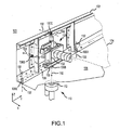
- an exemplary assembly task involves the joining of one or more components of a structure 102.
- a "skin" 104 of the box-type structure is shown in dotted lines, and generally defines an interior region 105 and exterior region 103. It will be understood that the particular beams, holes, and other components shown in FIG. 1 are merely examples, and in no way limits the range of applicable embodiments.
- FIG. 1 Two portions of an assembly system are illustrated in FIG. 1 : an external portion 110, and an internal portion 120.
- these two systems may be referred to herein as “external assembly system” 110 and “internal assembly system” 120, respectively, even though in practice they may be independent systems or two parts of the same system.
- Each assembly system 110 will typically include various end-effectors, actuators, and/or tools configured to perform the task at hand, and will also typically be attached to a robotic device and associated computer system (not shown in FIG. 1 ).
- fasteners 130 A number of instrumented fasteners (or simply “fasteners”) 130 have been attached to structure 102 at various points. In the illustrated embodiment, five such fasteners (130A, 130B, 130C, 130D, and 130E) are shown. In order to illustrate operation of the various embodiments, it is assumed that these fasteners 130 are "tack" fasteners - i.e., fasteners that help stabilize structure 102 temporarily, and which are replaced with a second, likely stronger, more permanent type of fastener, and which help with installing such permanent type fasteners in adjacent holes. Alternatively, fasteners 130 may be permanent fasteners.
- FIG. 1 shows internal assembly system 120 located above fastener 130B, and external assembly system 110 located below fastener 130B.
- each fastener 130 is configured to produce one or more light beacons 132 that can be sensed by assembly systems 110 and 120.
- This light beacon in addition to providing a reference for alignment, may also include encoded information (encoded by controller 230) regarding the nature and/or location of the respective fastener 130.
- fasteners 130 when activated, produce antipodal light beacons projecting outward along their major axes.
- external assembly system 110 When moving into position, external assembly system 110 receives beacon 132 through a port or lens 112. At the same time, internal assembly system 120 receives the antipodal beacon 132 within a sensor along underside 122 of the structure (not shown). Assembly systems 120 may then iteratively move themselves into the correct position and alignment based on the location of the received light on the sensor (i.e., aligned with the z axis as defined in this figure). That is, known techniques may be used to align the sensor such that it is centered and exhibits normality with respect to beacon 132.
- assembly systems 110 and 120 may then complete the required task before moving on to the next position (e.g., the next fastener 130).
- the next position e.g., the next fastener 130
- the position of known fastener locations between neighboring fasteners 130 may be computed, followed by installation of permanent fasteners therein.
- fastener 130 includes a body 202 encasing a light source 210, another light source 212, one or more power sources 220, and a controller 230.
- Body 202 which has a major axis corresponding in this figure to the z-axis, may include a generally hollow, cylindrical cavity 240 large enough to fit the power source(s) 220 and controller 230.
- Body 202 may be threaded as shown to receive a corresponding nut 204, thus securing the components of structure 102.
- Body 202 may comprise any suitable material or combination of materials, including various plastics, ceramics, metals, and composites. Furthermore, body 202 may have any configuration and size, and is not limited to the tack fastener shown in FIG. 2 . In one embodiment, body 202 is generally cylindrical and has a diameter between approximately 0.15 - 0.50 inches
- Light sources 210 and 212 are oriented such that, when activated by controller 230, and powered by power source 220, they produce opposing beacons 132A and 132B, respectively, which have maximum intensity in antipodal directions.
- External cavities 242 and 244 are shown adjacent to light sources 210 and 212, and function to protect light sources 210 and 212 from external impact and other forces.
- Light sources 210 and 212 may comprise any suitable light-emitting component, for example, a conventional light-emitting diode (LED). Furthermore, other parts of the electromagnetic spectrum other than visible light may be used.
- Power source 220 may include one or more batteries, such as various small conventional lithium-ion batteries known in the art.
- FIG. 3 shows a simplified block diagram of instrumented fastener 130.
- Controller 230 which receives a suitable voltage V from power source 220, selectively provides a current through resistor 310 to LED 210.
- Controller 230 may include any combination of hardware, software, and firmware configured to suitably control light sources 210 and 212.
- controller 230 may include a microprocessor, memory, I/O as is conventionally known.
- Controller 230 (or other components provided within body 202) may also be configured to receive external commands through, for example, a wireless communication protocol.
- Controller 230 may activate light sources 210 and 212 periodically, at predetermined times, or in response to an external instruction or stimulus. That is, assembly systems 110 and/or 120 (or the computer systems attached thereto) may be configured to wirelessly issue an instruction to controller 230 such that controller 230 activates the light sources only when the assembly systems are proximate to the fastener 130. Alternatively, controller 230 may sense the presence of the assembly system (e.g., via a conventional passive or active RFID scheme) and activate the light sources only when the assembly system is within a predetermined distance of fastener 130.
- beacons 132 it is desirable for beacons 132 to encode information relating to the nature and/or position of fastener 130.
- certain data 235 is preferably stored within controller 230 a priori. This data may include information regarding, for example, the part ID of fastener 130, its intended location within the structure (i.e., the particular airframe structure to which it is affixed), or any other such information.
- the data may be encoded and communicated in any desired manner.
- the data is stored as a digital word, and is communicated as a serial bit stream within beacon 132 by modulating the intensity of the beacon at a suitable clock rate. This modulation of intensity can then be read by sensors incorporated into the end-effectors of the assembly systems.
- a method of using an exemplary instrumented fastener to align an assembly system includes affixing an instrumented fastener to a structure (block 410), sending an instruction to the instrumented fastener to activate the instrumented fastener (block 420).
- the instrumented fastener produces a first light beacon along a first direction.
- the first light beacon may include information regarding the instrumented fastener.
- the instrumented fastener may also produce a second light beacon along a second direction antipodal to the first direction.
- the light beacon(s) are detected at the assembly system (block 430).
- the assembly system is aligned adjacent the instrumented fastener based on the direction of the light beacon(s) (block 440). For example, an external portion of the assembly system is aligned based on the first direction of the first light beacon, and an internal portion of the assembly system is aligned based on the second direction of the second light beacon.
- aligning the external portion of the assembly system includes alignment of an end-effector exhibiting four degrees of freedom.
- aligning the external portion of the assembly system includes determining a part number of the instrumented fastener based on the information included in the first light beacon.
- the method may further include utilizing the assembly system to replace the instrumented fastener with a permanent fastener (block 460).
Abstract
Description
- The embodiments described herein generally relate to assembly and testing of structures, and more particularly relate to methods and apparatus for providing information regarding location and orientation of an assembly system with respect to such structures using intelligent fasteners.
- During the assembly of aircraft airframe structures and other such box-type structures - in which one portion of an assembly system operates on the outside of the structure and another portion of the assembly system operates on the inside of the structure - it is desirable for the various components of the assembly system to be accurately positioned and aligned, facilitating the synchronous performance of assembly tasks. Such tasks include, for example, installing rivets and other fasteners, tasks that may be accomplished manually or through the use of automated assembly systems.
- In automated assembly systems, detailed information regarding the location and orientation of the assembly system and its various end-effectors with respect to the structure is preferably generated and maintained. One common method of addressing this positioning problem involves coordinating the position of the internal and external assembly system using "tack" fasteners, which are installed at structural interfaces to stabilize components during assembly. The location of these fasteners can be detected by both the internal and external portions of the assembly system using conventional vision system cameras.
- Another common technique involves the use of a small magnet, which can be placed inside a hole of the internal structural component, along with a magnet centroid finder that is moved along the outer surface until the center (i.e., the magnet) is located. An "X" or other such indicia is then marked on the surface, which is then identified by a vision system camera on the external portion of the assembly unit.
- Such systems, however, are somewhat imprecise and generally provide only two-dimensional guidance (e.g., x and y position). Furthermore, such passive tacks are not configured to identify the specific structural location in which they are placed.
- Accordingly, it is desirable to provide improved fasteners and aligning methods for such fasteners during joining and testing operations. Other desirable features and characteristics of the various embodiments will become apparent from the subsequent detailed description and the appended claims, taken in conjunction with the accompanying drawings and the foregoing technical field and background.
- The invention is set out in the independent claims. Preferred or optional features are set out in the dependent claims thereto.
- Methods and apparatus are provided for improved assembly methods using intelligent fasteners. In one embodiment, an instrumented fastener (e.g., a "tack" fastener) includes one or more light sources (e.g., light-emitting diodes) configured to produce a light beacon that encodes information regarding the instrumented fastener (e.g., part number), wherein the direction of the light beacon can be used to align external and/or internal assembly systems to the instrumented fastener. The light beacon may be activated automatically, or via an instruction received from an external system. In the context of aircraft assembly, a plurality of such fasteners may be affixed to one or more airframe parts and used to autonomously assemble the various structures.
- Various embodiments will hereinafter be described in conjunction with the following drawing figures, wherein like numerals denote like elements, and
-
FIG. 1 is an isometric partial cut-away view of an assembly useful in describing various embodiments; -
FIG. 2 is a conceptual cross-section view of an instrumented fastener in accordance with an exemplary embodiment; -
FIG. 3 is a schematic block diagram of an exemplary instrumented fastener; and -
FIG. 4 is an illustration of a method of using an exemplary instrumental fastener. - The following detailed description is merely exemplary in nature and is not intended to limit the described embodiments or the application and uses of the described embodiments. Furthermore, there is no intention to be bound by any expressed or implied theory presented in the preceding technical field, background, brief summary or the following detailed description.
- For simplicity and clarity of illustration, the drawing figures depict the general structure and/or manner of construction of the various embodiments. Descriptions and details of well-known features and techniques may be omitted to avoid unnecessarily obscuring other features. Elements in the drawings figures are not necessarily drawn to scale: the dimensions of some features may be exaggerated relative to other elements to improve understanding of the example embodiments.
- Terms of enumeration such as "first," "second," "third," and the like may be used for distinguishing between similar elements and not necessarily for describing a particular spatial or chronological order. These terms, so used, are interchangeable under appropriate circumstances. The embodiments described herein are, for example, capable of use in sequences other than those illustrated or otherwise described herein. Unless expressly stated otherwise, "connected" means that one element/node/feature is directly joined to (or directly communicates with) another element/node/feature, but not necessarily mechanically. Likewise, unless expressly stated otherwise, "coupled" means that one element/node/feature is directly or indirectly joined to (or directly or indirectly communicates with) another element/node/feature, but not necessarily mechanically.
- The terms "comprise," "include," "have" and any variations thereof are used synonymously to denote non-exclusive inclusion. The terms "left," right," "in," "out," "front," "back," "up," "down," and other such directional terms are used to describe relative positions, not necessarily absolute positions in space. The term "exemplary" is used in the sense of "example," rather than "ideal."
- In the interest of conciseness, conventional techniques, structures, and principles known by those skilled in the art may not be described herein, including, for example, conventional structural design, basic principles of electronics, light sources, LEDs, sensors, and the like.
- In general, the various embodiments described herein relate to a form of intelligent fastener that assists with guiding an assembly system into proper position and alignment. More particularly, referring to
FIG. 1 , an exemplary assembly task involves the joining of one or more components of astructure 102. In this figure, a "skin" 104 of the box-type structure is shown in dotted lines, and generally defines aninterior region 105 andexterior region 103. It will be understood that the particular beams, holes, and other components shown inFIG. 1 are merely examples, and in no way limits the range of applicable embodiments. - Two portions of an assembly system are illustrated in
FIG. 1 : anexternal portion 110, and aninternal portion 120. For ease of reference, these two systems may be referred to herein as "external assembly system" 110 and "internal assembly system" 120, respectively, even though in practice they may be independent systems or two parts of the same system. Eachassembly system 110 will typically include various end-effectors, actuators, and/or tools configured to perform the task at hand, and will also typically be attached to a robotic device and associated computer system (not shown inFIG. 1 ). - A number of instrumented fasteners (or simply "fasteners") 130 have been attached to
structure 102 at various points. In the illustrated embodiment, five such fasteners (130A, 130B, 130C, 130D, and 130E) are shown. In order to illustrate operation of the various embodiments, it is assumed that thesefasteners 130 are "tack" fasteners - i.e., fasteners that help stabilizestructure 102 temporarily, and which are replaced with a second, likely stronger, more permanent type of fastener, and which help with installing such permanent type fasteners in adjacent holes. Alternatively,fasteners 130 may be permanent fasteners. - It is desirable for
internal assembly system 120 andexternal assembly system 110 to work synchronously to locate eachfastener 130 and align themselves correctly such that any subsequent processing can be precisely performed - e.g., between two adjacent or neighboring tag fasteners. The scenario illustrated inFIG. 1 showsinternal assembly system 120 located abovefastener 130B, andexternal assembly system 110 located belowfastener 130B. - To achieve this alignment, and as described in further detail below, each
fastener 130 is configured to produce one ormore light beacons 132 that can be sensed byassembly systems respective fastener 130. In the illustrated embodiment, for example,fasteners 130, when activated, produce antipodal light beacons projecting outward along their major axes. - When moving into position,
external assembly system 110 receivesbeacon 132 through a port orlens 112. At the same time,internal assembly system 120 receives theantipodal beacon 132 within a sensor alongunderside 122 of the structure (not shown).Assembly systems 120 may then iteratively move themselves into the correct position and alignment based on the location of the received light on the sensor (i.e., aligned with the z axis as defined in this figure). That is, known techniques may be used to align the sensor such that it is centered and exhibits normality with respect tobeacon 132. - Once in the correct position and orientation,
assembly systems fasteners 130 may be computed, followed by installation of permanent fasteners therein. - Referring to
FIG. 2 , an exemplary instrumentedfastener 130 will now be described. In this embodiment,fastener 130 includes abody 202 encasing alight source 210, anotherlight source 212, one ormore power sources 220, and acontroller 230.Body 202, which has a major axis corresponding in this figure to the z-axis, may include a generally hollow,cylindrical cavity 240 large enough to fit the power source(s) 220 andcontroller 230.Body 202 may be threaded as shown to receive acorresponding nut 204, thus securing the components ofstructure 102. -
Body 202 may comprise any suitable material or combination of materials, including various plastics, ceramics, metals, and composites. Furthermore,body 202 may have any configuration and size, and is not limited to the tack fastener shown inFIG. 2 . In one embodiment,body 202 is generally cylindrical and has a diameter between approximately 0.15 - 0.50 inches -
Light sources controller 230, and powered bypower source 220, they produce opposingbeacons External cavities light sources light sources -
Light sources Power source 220 may include one or more batteries, such as various small conventional lithium-ion batteries known in the art. -
FIG. 3 shows a simplified block diagram of instrumentedfastener 130.Controller 230, which receives a suitable voltage V frompower source 220, selectively provides a current throughresistor 310 toLED 210.Controller 230 may include any combination of hardware, software, and firmware configured to suitably controllight sources controller 230 may include a microprocessor, memory, I/O as is conventionally known. Controller 230 (or other components provided within body 202) may also be configured to receive external commands through, for example, a wireless communication protocol. -
Controller 230 may activatelight sources assembly systems 110 and/or 120 (or the computer systems attached thereto) may be configured to wirelessly issue an instruction tocontroller 230 such thatcontroller 230 activates the light sources only when the assembly systems are proximate to thefastener 130. Alternatively,controller 230 may sense the presence of the assembly system (e.g., via a conventional passive or active RFID scheme) and activate the light sources only when the assembly system is within a predetermined distance offastener 130. - Furthermore, as mentioned above, it is desirable for
beacons 132 to encode information relating to the nature and/or position offastener 130. Accordingly,certain data 235 is preferably stored within controller 230 a priori. This data may include information regarding, for example, the part ID offastener 130, its intended location within the structure (i.e., the particular airframe structure to which it is affixed), or any other such information. The data may be encoded and communicated in any desired manner. In one embodiment, for example, the data is stored as a digital word, and is communicated as a serial bit stream withinbeacon 132 by modulating the intensity of the beacon at a suitable clock rate. This modulation of intensity can then be read by sensors incorporated into the end-effectors of the assembly systems. - Referring to
FIG. 4 , a method of using an exemplary instrumented fastener to align an assembly system includes affixing an instrumented fastener to a structure (block 410), sending an instruction to the instrumented fastener to activate the instrumented fastener (block 420). When activated, the instrumented fastener produces a first light beacon along a first direction. The first light beacon may include information regarding the instrumented fastener. The instrumented fastener may also produce a second light beacon along a second direction antipodal to the first direction. - The light beacon(s) are detected at the assembly system (block 430). The assembly system is aligned adjacent the instrumented fastener based on the direction of the light beacon(s) (block 440). For example, an external portion of the assembly system is aligned based on the first direction of the first light beacon, and an internal portion of the assembly system is aligned based on the second direction of the second light beacon. In some embodiments, aligning the external portion of the assembly system includes alignment of an end-effector exhibiting four degrees of freedom. In some embodiments, aligning the external portion of the assembly system includes determining a part number of the instrumented fastener based on the information included in the first light beacon.
- The method may further include utilizing the assembly system to replace the instrumented fastener with a permanent fastener (block 460).
- While at least one exemplary embodiment has been presented in the foregoing detailed description, it should be appreciated that a vast number of variations exist. It should also be appreciated that the exemplary embodiment or exemplary embodiments are only examples, and are not intended to limit the scope, applicability, or configuration of the described embodiments in any way. Rather, the foregoing detailed description will provide those skilled in the art with a convenient road map for implementing the exemplary embodiment or exemplary embodiments. It should be understood that various changes can be made in the function and arrangement of elements without departing from the scope as set forth in the appended claims and the legal equivalents thereof.
Claims (20)
- An instrumented fastener comprising:a fastener body having a first end and a second end;a power source within the fastener body;a controller within the fastener body, the controller electrically coupled to the power source;a first light source fixed to the first end of the fastener body and communicatively coupled to the controller, the first light source configured to produce a first light beacon along a first direction when activated;wherein the controller is configured to activate the first light source such that the first light beacon includes information regarding the instrumented fastener.
- The instrumented fastener of claim 1, further including a second light source fixed to the second end of the fastener body and communicatively coupled to the controller, the second light source configured to produce a second light beacon along a second direction when activated.
- The instrumented fastener of claim 2, wherein the first direction and second direction are substantially antipodal.
- The instrumented fastener of claim 1, wherein the first light beacon includes information utilizing a serial bit stream comprising one or more digital words.
- The instrumented fastener of claim 1, wherein the first light beacon includes information regarding a part ID of the instrumented fastener.
- The instrumented fastener of claim 1, wherein the first light source is a light emitting diode.
- The instrumented fastener of claim 1, wherein the first or second end of the fastener body is externally threaded and configured to receive a corresponding nut.
- The instrumented fastener of claim 1, wherein the power source is a battery.
- The instrumented fastener of claim 1, wherein the fastener body has a diameter between approximately 0.15 - 0.50 inches.
- The instrumented fastener of claim 1, wherein the controller is configured to activate the first light source in response to an external command.
- The instrumented fastener of claim 10, wherein the controller is configured to receive the external command from an assembly system.
- A method of aligning an assembly system, the method comprising:affixing an instrumented fastener to the structure, the instrumented fastener configured to produce a first light beacon along a first direction when activated, wherein the first light beacon includes information regarding the instrumented fastener;detecting, at an assembly system, the first light beacon; andaligning the assembly system adjacent the instrumented fastener based on the direction of the first light beacon.
- The method of claim 12, further including, after the aligning step, utilizing the assembly system to replace the instrumented fastener with a permanent fastener.
- The method of claim 12, wherein the instrumented fastener is further configured to produce a second light beacon along a second direction antipodal to the first direction, and wherein the aligning step further includes aligning an external portion of the assembly system based on the first direction of the first light beacon, and aligning an internal portion of the assembly system based on the second direction of the second light beacon.
- The method of claim 12, further including:sending an instruction to the instrumented fastener; andactivating the instrumented fastener in response to the instruction.
- A method for assembling an aircraft, the method comprising:affixing an instrumented fastener to an airframe structure of the aircraft, the instrumented fastener configured to produce, when activated, a first light beacon along a first direction, and a second light beacon along a second direction antipodal to the first direction, wherein the first and second light beacons include information regarding the instrumented fastener;detecting, at an external portion of an assembly system, the first light beacon;detecting, at an internal portion of the assembly system, the second light beacon;aligning the external portion of the assembly system adjacent the instrumented fastener based on the first direction of the first light beacon; andaligning the internal portion of the assembly system adjacent the instrumented based on the second direction of the second light beacon.
- The method of claim 16, further including, after the aligning step, utilizing the external and internal portions of the assembly system to replace the instrumented fastener with a permanent fastener.
- The method of claim 16, further including:sending an instruction to the instrumented fastener; andactivating the instrumented fastener in response to the instruction.
- The method of claim 16, wherein aligning the external portion of the assembly system includes alignment of an end-effector exhibiting four degrees of freedom.
- The method of claim 16, wherein aligning the external portion of the assembly system includes determining a part number of the instrumented fastener based on the information included in the first light beacon.
Applications Claiming Priority (1)
| Application Number | Priority Date | Filing Date | Title |
|---|---|---|---|
| US11/756,447 US7937817B2 (en) | 2007-05-31 | 2007-05-31 | Methods and apparatus for an instrumented fastener |
Publications (2)
| Publication Number | Publication Date |
|---|---|
| EP1998138A1 true EP1998138A1 (en) | 2008-12-03 |
| EP1998138B1 EP1998138B1 (en) | 2012-03-07 |
Family
ID=39714193
Family Applications (1)
| Application Number | Title | Priority Date | Filing Date |
|---|---|---|---|
| EP08156872A Active EP1998138B1 (en) | 2007-05-31 | 2008-05-23 | Method and apparatus for an instrumented fastener |
Country Status (7)
| Country | Link |
|---|---|
| US (1) | US7937817B2 (en) |
| EP (1) | EP1998138B1 (en) |
| JP (1) | JP5114296B2 (en) |
| CN (1) | CN101315273B (en) |
| AT (1) | ATE548631T1 (en) |
| ES (1) | ES2383839T3 (en) |
| HK (1) | HK1122612A1 (en) |
Families Citing this family (7)
| Publication number | Priority date | Publication date | Assignee | Title |
|---|---|---|---|---|
| US8301302B2 (en) | 2008-05-08 | 2012-10-30 | The Boeing Company | Synchronous robotic operation on a structure having a confined space |
| US20100217437A1 (en) * | 2009-02-24 | 2010-08-26 | Branko Sarh | Autonomous robotic assembly system |
| US8666546B2 (en) * | 2009-07-10 | 2014-03-04 | The Boeing Company | Autonomous robotic platform |
| US8544163B2 (en) | 2011-04-30 | 2013-10-01 | The Boeing Company | Robot having obstacle avoidance mechanism |
| US9764464B2 (en) | 2011-08-03 | 2017-09-19 | The Boeing Company | Robot including telescopic assemblies for positioning an end effector |
| US10386254B2 (en) * | 2016-04-25 | 2019-08-20 | The Boeing Company | Fastener Status Detection System |
| US10873357B2 (en) | 2017-05-02 | 2020-12-22 | Deere & Company | Smart attachment for a work vehicle |
Citations (3)
| Publication number | Priority date | Publication date | Assignee | Title |
|---|---|---|---|---|
| US20010024283A1 (en) | 2000-03-21 | 2001-09-27 | Romain Granger | System for identifying the position of a three-dimensional machine in a fixed frame of reference |
| US20030038933A1 (en) | 2001-04-19 | 2003-02-27 | Dimensional Photonics Inc. | Calibration apparatus, system and method |
| US20070262933A1 (en) * | 2006-05-11 | 2007-11-15 | Advanced Lighting Systems, Inc. A Minnesota Corporation | System and method for mounting LED's on a display surface |
Family Cites Families (17)
| Publication number | Priority date | Publication date | Assignee | Title |
|---|---|---|---|---|
| US2206036A (en) * | 1938-07-27 | 1940-07-02 | Herson Jacob | Distance measuring apparatus and system |
| US4277170A (en) * | 1979-11-01 | 1981-07-07 | Miles Richard B | Laser beacon and optical detector system for aircraft collision hazard determination |
| US4934885A (en) * | 1985-02-25 | 1990-06-19 | The Boeing Company | Tack fastener |
| KR950005415B1 (en) * | 1986-09-19 | 1995-05-24 | 텍사스 인스트루먼츠 인코포레이티드 | Mobile robot system |
| US5202568A (en) * | 1991-09-03 | 1993-04-13 | Central Ohio Plastic Corporation | Determining the presence, position, and integrity of reinforcing mounting clips by utilizing photoelectric means |
| US5549803A (en) * | 1994-01-14 | 1996-08-27 | Honeywell Inc. | Smart fastener |
| FR2721395B1 (en) * | 1994-06-17 | 1996-08-14 | Homer Eaton | Method for locating a trihedron in space and device for implementing this method. |
| US5577829A (en) * | 1995-01-09 | 1996-11-26 | Hall; Timothy E. | Flashlight with tool bit attachment |
| US6056283A (en) * | 1999-02-08 | 2000-05-02 | The Boeing Company | Tack fastener |
| US6196779B1 (en) * | 1999-02-11 | 2001-03-06 | The Boeing Company | Temporary fastener with projecting tool-guide bushing |
| US6643019B1 (en) * | 2000-04-13 | 2003-11-04 | Jack D. Jeanneret | Laser alignment device |
| US6741364B2 (en) * | 2002-08-13 | 2004-05-25 | Harris Corporation | Apparatus for determining relative positioning of objects and related methods |
| TWM242685U (en) * | 2003-03-04 | 2004-09-01 | Quarton Inc | Three-direction laser indicator |
| AU2003902259A0 (en) * | 2003-05-13 | 2003-05-29 | Telezygology Inc. | Improved assembly system |
| US7216436B2 (en) * | 2004-08-24 | 2007-05-15 | Bell Helicopter Textron Inc. | Method and apparatus for locating and aligning fasteners |
| US20070204473A1 (en) * | 2006-03-03 | 2007-09-06 | Honda Motor Co., Ltd. | Spindle locating laser for nut runner |
| US7557936B2 (en) * | 2006-04-12 | 2009-07-07 | Toyota Motor Engineering & Manufacturing North America, Inc. | Digitizer adapter |
-
2007
- 2007-05-31 US US11/756,447 patent/US7937817B2/en active Active
-
2008
- 2008-05-23 AT AT08156872T patent/ATE548631T1/en active
- 2008-05-23 EP EP08156872A patent/EP1998138B1/en active Active
- 2008-05-23 ES ES08156872T patent/ES2383839T3/en active Active
- 2008-06-02 JP JP2008144312A patent/JP5114296B2/en active Active
- 2008-06-02 CN CN2008101087967A patent/CN101315273B/en active Active
-
2009
- 2009-01-21 HK HK09100672.6A patent/HK1122612A1/en unknown
Patent Citations (3)
| Publication number | Priority date | Publication date | Assignee | Title |
|---|---|---|---|---|
| US20010024283A1 (en) | 2000-03-21 | 2001-09-27 | Romain Granger | System for identifying the position of a three-dimensional machine in a fixed frame of reference |
| US20030038933A1 (en) | 2001-04-19 | 2003-02-27 | Dimensional Photonics Inc. | Calibration apparatus, system and method |
| US20070262933A1 (en) * | 2006-05-11 | 2007-11-15 | Advanced Lighting Systems, Inc. A Minnesota Corporation | System and method for mounting LED's on a display surface |
Also Published As
| Publication number | Publication date |
|---|---|
| EP1998138B1 (en) | 2012-03-07 |
| US20080295314A1 (en) | 2008-12-04 |
| ES2383839T3 (en) | 2012-06-26 |
| JP2009078347A (en) | 2009-04-16 |
| JP5114296B2 (en) | 2013-01-09 |
| CN101315273A (en) | 2008-12-03 |
| ATE548631T1 (en) | 2012-03-15 |
| HK1122612A1 (en) | 2009-05-22 |
| US7937817B2 (en) | 2011-05-10 |
| CN101315273B (en) | 2011-12-28 |
Similar Documents
| Publication | Publication Date | Title |
|---|---|---|
| EP1998138A1 (en) | Methods and apparatus for an instrumented fastener | |
| CN106477068A (en) | Robot system and the method for operation robot system | |
| US11042074B2 (en) | Flying camera with string assembly for localization and interaction | |
| CA2657085C (en) | Synchronous robotic operation on a structure having a confined space | |
| JP7236640B2 (en) | tool system | |
| ES2818918T3 (en) | Component connection without mounting frames | |
| JP6671113B2 (en) | Measurement-based system for operating flexible manufacturing systems | |
| US10435143B1 (en) | Unmanned aerial vehicle with ports configured to receive swappable components | |
| CN104827482A (en) | Robotic platform capable of moving automatically | |
| ATE445172T1 (en) | THREE-DIMENSIONAL ROOM MONITORING WITH CONFIGURATION MODE TO DETERMINE THE PROTECTIVE FIELDS | |
| US11014243B1 (en) | System and method for instructing a device | |
| KR101614620B1 (en) | Aerial Robot System Based on Multi-rotor for Mechanical Tasks | |
| CN112571415A (en) | Robot autonomous door opening method and system based on visual guidance | |
| CN109958589A (en) | For safeguarding the device and method of wind turbine blade | |
| CN205343173U (en) | Trick coordinate system calibration device of robot | |
| CN106347708A (en) | Method and system for controlling automated operations on a workpiece | |
| CN204640230U (en) | A kind of can the robot platform of autonomous | |
| EP3289858B1 (en) | Robotic arm and preparation cup system | |
| TW202119055A (en) | Systems and methods for calibrating nonvisible light emitting sensors using alignment targets | |
| US11235396B2 (en) | System and method for self contained through sensor for determining an actuation position for a machine | |
| US20200264581A1 (en) | System and method for automated aperture alignment in response to detecting an object | |
| Jain et al. | Design and development of underwater vehicle: ANAHITA | |
| KR102658278B1 (en) | Mobile robot and method of aligning robot arm thereof | |
| Sharma et al. | Design of an intelligent security robot for collision free navigation applications | |
| Sharma et al. | Design and implementation of obstacle detection algorithm in robotics |
Legal Events
| Date | Code | Title | Description |
|---|---|---|---|
| PUAI | Public reference made under article 153(3) epc to a published international application that has entered the european phase |
Free format text: ORIGINAL CODE: 0009012 |
|
| 17P | Request for examination filed |
Effective date: 20080527 |
|
| AK | Designated contracting states |
Kind code of ref document: A1 Designated state(s): AT BE BG CH CY CZ DE DK EE ES FI FR GB GR HR HU IE IS IT LI LT LU LV MC MT NL NO PL PT RO SE SI SK TR |
|
| AX | Request for extension of the european patent |
Extension state: AL BA MK RS |
|
| 17Q | First examination report despatched |
Effective date: 20090128 |
|
| AKX | Designation fees paid |
Designated state(s): AT BE BG CH CY CZ DE DK EE ES FI FR GB GR HR HU IE IS IT LI LT LU LV MC MT NL NO PL PT RO SE SI SK TR |
|
| GRAP | Despatch of communication of intention to grant a patent |
Free format text: ORIGINAL CODE: EPIDOSNIGR1 |
|
| RTI1 | Title (correction) |
Free format text: METHOD AND APPARATUS FOR AN INSTRUMENTED FASTENER |
|
| GRAS | Grant fee paid |
Free format text: ORIGINAL CODE: EPIDOSNIGR3 |
|
| GRAA | (expected) grant |
Free format text: ORIGINAL CODE: 0009210 |
|
| AK | Designated contracting states |
Kind code of ref document: B1 Designated state(s): AT BE BG CH CY CZ DE DK EE ES FI FR GB GR HR HU IE IS IT LI LT LU LV MC MT NL NO PL PT RO SE SI SK TR |
|
| REG | Reference to a national code |
Ref country code: GB Ref legal event code: FG4D |
|
| REG | Reference to a national code |
Ref country code: AT Ref legal event code: REF Ref document number: 548631 Country of ref document: AT Kind code of ref document: T Effective date: 20120315 Ref country code: CH Ref legal event code: EP |
|
| REG | Reference to a national code |
Ref country code: IE Ref legal event code: FG4D |
|
| REG | Reference to a national code |
Ref country code: DE Ref legal event code: R096 Ref document number: 602008013885 Country of ref document: DE Effective date: 20120503 |
|
| REG | Reference to a national code |
Ref country code: ES Ref legal event code: FG2A Ref document number: 2383839 Country of ref document: ES Kind code of ref document: T3 Effective date: 20120626 |
|
| REG | Reference to a national code |
Ref country code: NL Ref legal event code: VDEP Effective date: 20120307 |
|
| PG25 | Lapsed in a contracting state [announced via postgrant information from national office to epo] |
Ref country code: LT Free format text: LAPSE BECAUSE OF FAILURE TO SUBMIT A TRANSLATION OF THE DESCRIPTION OR TO PAY THE FEE WITHIN THE PRESCRIBED TIME-LIMIT Effective date: 20120307 Ref country code: NL Free format text: LAPSE BECAUSE OF FAILURE TO SUBMIT A TRANSLATION OF THE DESCRIPTION OR TO PAY THE FEE WITHIN THE PRESCRIBED TIME-LIMIT Effective date: 20120307 Ref country code: NO Free format text: LAPSE BECAUSE OF FAILURE TO SUBMIT A TRANSLATION OF THE DESCRIPTION OR TO PAY THE FEE WITHIN THE PRESCRIBED TIME-LIMIT Effective date: 20120607 Ref country code: HR Free format text: LAPSE BECAUSE OF FAILURE TO SUBMIT A TRANSLATION OF THE DESCRIPTION OR TO PAY THE FEE WITHIN THE PRESCRIBED TIME-LIMIT Effective date: 20120307 |
|
| LTIE | Lt: invalidation of european patent or patent extension |
Effective date: 20120307 |
|
| PG25 | Lapsed in a contracting state [announced via postgrant information from national office to epo] |
Ref country code: GR Free format text: LAPSE BECAUSE OF FAILURE TO SUBMIT A TRANSLATION OF THE DESCRIPTION OR TO PAY THE FEE WITHIN THE PRESCRIBED TIME-LIMIT Effective date: 20120608 Ref country code: FI Free format text: LAPSE BECAUSE OF FAILURE TO SUBMIT A TRANSLATION OF THE DESCRIPTION OR TO PAY THE FEE WITHIN THE PRESCRIBED TIME-LIMIT Effective date: 20120307 Ref country code: LV Free format text: LAPSE BECAUSE OF FAILURE TO SUBMIT A TRANSLATION OF THE DESCRIPTION OR TO PAY THE FEE WITHIN THE PRESCRIBED TIME-LIMIT Effective date: 20120307 |
|
| REG | Reference to a national code |
Ref country code: AT Ref legal event code: MK05 Ref document number: 548631 Country of ref document: AT Kind code of ref document: T Effective date: 20120307 |
|
| PG25 | Lapsed in a contracting state [announced via postgrant information from national office to epo] |
Ref country code: CY Free format text: LAPSE BECAUSE OF FAILURE TO SUBMIT A TRANSLATION OF THE DESCRIPTION OR TO PAY THE FEE WITHIN THE PRESCRIBED TIME-LIMIT Effective date: 20120307 |
|
| PG25 | Lapsed in a contracting state [announced via postgrant information from national office to epo] |
Ref country code: IS Free format text: LAPSE BECAUSE OF FAILURE TO SUBMIT A TRANSLATION OF THE DESCRIPTION OR TO PAY THE FEE WITHIN THE PRESCRIBED TIME-LIMIT Effective date: 20120707 Ref country code: EE Free format text: LAPSE BECAUSE OF FAILURE TO SUBMIT A TRANSLATION OF THE DESCRIPTION OR TO PAY THE FEE WITHIN THE PRESCRIBED TIME-LIMIT Effective date: 20120307 Ref country code: PL Free format text: LAPSE BECAUSE OF FAILURE TO SUBMIT A TRANSLATION OF THE DESCRIPTION OR TO PAY THE FEE WITHIN THE PRESCRIBED TIME-LIMIT Effective date: 20120307 Ref country code: CZ Free format text: LAPSE BECAUSE OF FAILURE TO SUBMIT A TRANSLATION OF THE DESCRIPTION OR TO PAY THE FEE WITHIN THE PRESCRIBED TIME-LIMIT Effective date: 20120307 Ref country code: SE Free format text: LAPSE BECAUSE OF FAILURE TO SUBMIT A TRANSLATION OF THE DESCRIPTION OR TO PAY THE FEE WITHIN THE PRESCRIBED TIME-LIMIT Effective date: 20120307 Ref country code: BE Free format text: LAPSE BECAUSE OF FAILURE TO SUBMIT A TRANSLATION OF THE DESCRIPTION OR TO PAY THE FEE WITHIN THE PRESCRIBED TIME-LIMIT Effective date: 20120307 Ref country code: SI Free format text: LAPSE BECAUSE OF FAILURE TO SUBMIT A TRANSLATION OF THE DESCRIPTION OR TO PAY THE FEE WITHIN THE PRESCRIBED TIME-LIMIT Effective date: 20120307 Ref country code: RO Free format text: LAPSE BECAUSE OF FAILURE TO SUBMIT A TRANSLATION OF THE DESCRIPTION OR TO PAY THE FEE WITHIN THE PRESCRIBED TIME-LIMIT Effective date: 20120307 |
|
| PG25 | Lapsed in a contracting state [announced via postgrant information from national office to epo] |
Ref country code: SK Free format text: LAPSE BECAUSE OF FAILURE TO SUBMIT A TRANSLATION OF THE DESCRIPTION OR TO PAY THE FEE WITHIN THE PRESCRIBED TIME-LIMIT Effective date: 20120307 Ref country code: PT Free format text: LAPSE BECAUSE OF FAILURE TO SUBMIT A TRANSLATION OF THE DESCRIPTION OR TO PAY THE FEE WITHIN THE PRESCRIBED TIME-LIMIT Effective date: 20120709 |
|
| PG25 | Lapsed in a contracting state [announced via postgrant information from national office to epo] |
Ref country code: MC Free format text: LAPSE BECAUSE OF NON-PAYMENT OF DUE FEES Effective date: 20120531 |
|
| REG | Reference to a national code |
Ref country code: CH Ref legal event code: PL |
|
| PLBE | No opposition filed within time limit |
Free format text: ORIGINAL CODE: 0009261 |
|
| STAA | Information on the status of an ep patent application or granted ep patent |
Free format text: STATUS: NO OPPOSITION FILED WITHIN TIME LIMIT |
|
| PG25 | Lapsed in a contracting state [announced via postgrant information from national office to epo] |
Ref country code: DK Free format text: LAPSE BECAUSE OF FAILURE TO SUBMIT A TRANSLATION OF THE DESCRIPTION OR TO PAY THE FEE WITHIN THE PRESCRIBED TIME-LIMIT Effective date: 20120307 Ref country code: AT Free format text: LAPSE BECAUSE OF FAILURE TO SUBMIT A TRANSLATION OF THE DESCRIPTION OR TO PAY THE FEE WITHIN THE PRESCRIBED TIME-LIMIT Effective date: 20120307 Ref country code: LI Free format text: LAPSE BECAUSE OF NON-PAYMENT OF DUE FEES Effective date: 20120531 Ref country code: CH Free format text: LAPSE BECAUSE OF NON-PAYMENT OF DUE FEES Effective date: 20120531 |
|
| 26N | No opposition filed |
Effective date: 20121210 |
|
| REG | Reference to a national code |
Ref country code: IE Ref legal event code: MM4A |
|
| REG | Reference to a national code |
Ref country code: DE Ref legal event code: R097 Ref document number: 602008013885 Country of ref document: DE Effective date: 20121210 |
|
| PG25 | Lapsed in a contracting state [announced via postgrant information from national office to epo] |
Ref country code: IE Free format text: LAPSE BECAUSE OF NON-PAYMENT OF DUE FEES Effective date: 20120523 |
|
| PG25 | Lapsed in a contracting state [announced via postgrant information from national office to epo] |
Ref country code: BG Free format text: LAPSE BECAUSE OF FAILURE TO SUBMIT A TRANSLATION OF THE DESCRIPTION OR TO PAY THE FEE WITHIN THE PRESCRIBED TIME-LIMIT Effective date: 20120607 Ref country code: MT Free format text: LAPSE BECAUSE OF FAILURE TO SUBMIT A TRANSLATION OF THE DESCRIPTION OR TO PAY THE FEE WITHIN THE PRESCRIBED TIME-LIMIT Effective date: 20120307 |
|
| PG25 | Lapsed in a contracting state [announced via postgrant information from national office to epo] |
Ref country code: TR Free format text: LAPSE BECAUSE OF FAILURE TO SUBMIT A TRANSLATION OF THE DESCRIPTION OR TO PAY THE FEE WITHIN THE PRESCRIBED TIME-LIMIT Effective date: 20120307 |
|
| PG25 | Lapsed in a contracting state [announced via postgrant information from national office to epo] |
Ref country code: LU Free format text: LAPSE BECAUSE OF NON-PAYMENT OF DUE FEES Effective date: 20120523 |
|
| PG25 | Lapsed in a contracting state [announced via postgrant information from national office to epo] |
Ref country code: HU Free format text: LAPSE BECAUSE OF FAILURE TO SUBMIT A TRANSLATION OF THE DESCRIPTION OR TO PAY THE FEE WITHIN THE PRESCRIBED TIME-LIMIT Effective date: 20080523 |
|
| REG | Reference to a national code |
Ref country code: FR Ref legal event code: PLFP Year of fee payment: 9 |
|
| REG | Reference to a national code |
Ref country code: FR Ref legal event code: PLFP Year of fee payment: 10 |
|
| REG | Reference to a national code |
Ref country code: FR Ref legal event code: PLFP Year of fee payment: 11 |
|
| P01 | Opt-out of the competence of the unified patent court (upc) registered |
Effective date: 20230516 |
|
| PGFP | Annual fee paid to national office [announced via postgrant information from national office to epo] |
Ref country code: IT Payment date: 20230519 Year of fee payment: 16 Ref country code: FR Payment date: 20230525 Year of fee payment: 16 Ref country code: ES Payment date: 20230601 Year of fee payment: 16 Ref country code: DE Payment date: 20230530 Year of fee payment: 16 |
|
| PGFP | Annual fee paid to national office [announced via postgrant information from national office to epo] |
Ref country code: GB Payment date: 20230529 Year of fee payment: 16 |