EP1998145A2 - Microsensor capable of detecting a distance change or a series of distance changes between two points or zones of a structure when placed under stress - Google Patents
Microsensor capable of detecting a distance change or a series of distance changes between two points or zones of a structure when placed under stress Download PDFInfo
- Publication number
- EP1998145A2 EP1998145A2 EP08290493A EP08290493A EP1998145A2 EP 1998145 A2 EP1998145 A2 EP 1998145A2 EP 08290493 A EP08290493 A EP 08290493A EP 08290493 A EP08290493 A EP 08290493A EP 1998145 A2 EP1998145 A2 EP 1998145A2
- Authority
- EP
- European Patent Office
- Prior art keywords
- tooth
- support
- toothed wheel
- parts
- gear
- Prior art date
- Legal status (The legal status is an assumption and is not a legal conclusion. Google has not performed a legal analysis and makes no representation as to the accuracy of the status listed.)
- Granted
Links
- 238000004873 anchoring Methods 0.000 claims abstract description 20
- 238000001514 detection method Methods 0.000 claims abstract description 12
- 238000012423 maintenance Methods 0.000 claims description 3
- 230000002441 reversible effect Effects 0.000 claims description 3
- 238000006073 displacement reaction Methods 0.000 description 27
- 238000010586 diagram Methods 0.000 description 19
- 238000005530 etching Methods 0.000 description 18
- 239000000463 material Substances 0.000 description 9
- 230000002093 peripheral effect Effects 0.000 description 8
- 230000035882 stress Effects 0.000 description 8
- 238000000034 method Methods 0.000 description 4
- 230000035945 sensitivity Effects 0.000 description 4
- 230000004308 accommodation Effects 0.000 description 3
- 238000004026 adhesive bonding Methods 0.000 description 3
- 238000005452 bending Methods 0.000 description 3
- 210000004027 cell Anatomy 0.000 description 3
- 230000006835 compression Effects 0.000 description 3
- 238000007906 compression Methods 0.000 description 3
- 230000006866 deterioration Effects 0.000 description 3
- 239000003292 glue Substances 0.000 description 3
- 238000009434 installation Methods 0.000 description 3
- 229910052710 silicon Inorganic materials 0.000 description 3
- 239000010703 silicon Substances 0.000 description 3
- 230000010339 dilation Effects 0.000 description 2
- 230000000694 effects Effects 0.000 description 2
- 230000005672 electromagnetic field Effects 0.000 description 2
- 238000004519 manufacturing process Methods 0.000 description 2
- 230000003287 optical effect Effects 0.000 description 2
- 240000008042 Zea mays Species 0.000 description 1
- 239000000853 adhesive Substances 0.000 description 1
- 230000001070 adhesive effect Effects 0.000 description 1
- XAGFODPZIPBFFR-UHFFFAOYSA-N aluminium Chemical compound [Al] XAGFODPZIPBFFR-UHFFFAOYSA-N 0.000 description 1
- 229910052782 aluminium Inorganic materials 0.000 description 1
- 230000015572 biosynthetic process Effects 0.000 description 1
- 230000015556 catabolic process Effects 0.000 description 1
- 230000000295 complement effect Effects 0.000 description 1
- 238000006731 degradation reaction Methods 0.000 description 1
- 238000005553 drilling Methods 0.000 description 1
- 238000005516 engineering process Methods 0.000 description 1
- 238000004880 explosion Methods 0.000 description 1
- 230000014759 maintenance of location Effects 0.000 description 1
- 238000004806 packaging method and process Methods 0.000 description 1
- 230000003071 parasitic effect Effects 0.000 description 1
- 238000007747 plating Methods 0.000 description 1
- 230000036316 preload Effects 0.000 description 1
- 238000010079 rubber tapping Methods 0.000 description 1
- 230000008646 thermal stress Effects 0.000 description 1
- 238000002604 ultrasonography Methods 0.000 description 1
Images


Classifications
-
- G—PHYSICS
- G01—MEASURING; TESTING
- G01D—MEASURING NOT SPECIALLY ADAPTED FOR A SPECIFIC VARIABLE; ARRANGEMENTS FOR MEASURING TWO OR MORE VARIABLES NOT COVERED IN A SINGLE OTHER SUBCLASS; TARIFF METERING APPARATUS; MEASURING OR TESTING NOT OTHERWISE PROVIDED FOR
- G01D1/00—Measuring arrangements giving results other than momentary value of variable, of general application
- G01D1/04—Measuring arrangements giving results other than momentary value of variable, of general application giving integrated values
-
- G—PHYSICS
- G01—MEASURING; TESTING
- G01B—MEASURING LENGTH, THICKNESS OR SIMILAR LINEAR DIMENSIONS; MEASURING ANGLES; MEASURING AREAS; MEASURING IRREGULARITIES OF SURFACES OR CONTOURS
- G01B5/00—Measuring arrangements characterised by the use of mechanical techniques
- G01B5/30—Measuring arrangements characterised by the use of mechanical techniques for measuring the deformation in a solid, e.g. mechanical strain gauge
-
- G—PHYSICS
- G01—MEASURING; TESTING
- G01D—MEASURING NOT SPECIALLY ADAPTED FOR A SPECIFIC VARIABLE; ARRANGEMENTS FOR MEASURING TWO OR MORE VARIABLES NOT COVERED IN A SINGLE OTHER SUBCLASS; TARIFF METERING APPARATUS; MEASURING OR TESTING NOT OTHERWISE PROVIDED FOR
- G01D5/00—Mechanical means for transferring the output of a sensing member; Means for converting the output of a sensing member to another variable where the form or nature of the sensing member does not constrain the means for converting; Transducers not specially adapted for a specific variable
- G01D5/02—Mechanical means for transferring the output of a sensing member; Means for converting the output of a sensing member to another variable where the form or nature of the sensing member does not constrain the means for converting; Transducers not specially adapted for a specific variable using mechanical means
- G01D5/04—Mechanical means for transferring the output of a sensing member; Means for converting the output of a sensing member to another variable where the form or nature of the sensing member does not constrain the means for converting; Transducers not specially adapted for a specific variable using mechanical means using levers; using cams; using gearing
-
- G—PHYSICS
- G06—COMPUTING; CALCULATING OR COUNTING
- G06M—COUNTING MECHANISMS; COUNTING OF OBJECTS NOT OTHERWISE PROVIDED FOR
- G06M1/00—Design features of general application
- G06M1/04—Design features of general application for driving the stage of lowest order
- G06M1/041—Design features of general application for driving the stage of lowest order for drum-type indicating means
-
- G—PHYSICS
- G01—MEASURING; TESTING
- G01D—MEASURING NOT SPECIALLY ADAPTED FOR A SPECIFIC VARIABLE; ARRANGEMENTS FOR MEASURING TWO OR MORE VARIABLES NOT COVERED IN A SINGLE OTHER SUBCLASS; TARIFF METERING APPARATUS; MEASURING OR TESTING NOT OTHERWISE PROVIDED FOR
- G01D2205/00—Indexing scheme relating to details of means for transferring or converting the output of a sensing member
- G01D2205/10—Detecting linear movement
- G01D2205/14—Detecting linear movement by converting the linear movement into a rotary movement
Abstract
Description
La présente invention concerne le domaine des microcapteurs et a plus particulièrement pour objet un microcapteur apte à détecter et, préférentiellement aussi à compter, le nombre de cycles de variations de distance entre deux points ou zones d'une structure soumise à une action extérieure répétée, par exemple des cycles de températures ou de contraintes mécaniques comme par exemple le nombre de passages de véhicules sur un pont, générant un niveau de contrainte connu dans la structure.The present invention relates to the field of microsensors and more particularly to a microsensor capable of detecting, and preferably also counting, the number of cycles of variations in distance between two points or zones of a structure subjected to a repeated external action, for example temperature cycles or mechanical stresses such as the number of vehicle passes on a bridge, generating a known level of stress in the structure.
Dans le domaine des infrastructures routières, telle par exemple qu'un pont, il est important de connaître le nombre de véhicules l'ayant franchi afin d'en déterminer l'évolution structurelle.In the field of road infrastructure, such as a bridge, it is important to know the number of vehicles that have crossed over to determine its structural evolution.
A ce titre, on connaît le brevet
On connaît aussi d'autres dispositifs fonctionnant à l'aide d'ultrasons, de capteurs de pression ou de capteurs d'images et auxquels sont associés des moyens de traitement.Other devices operating using ultrasound, pressure sensors or image sensors and associated with processing means are also known.
Ces dispositifs présentent plusieurs inconvénients.These devices have several disadvantages.
Le premier d'entre eux concerne leur durée de vie : elle est limitée, au plus, à la durée de vie des moyens d'alimentation, à savoir des piles, soit environ un ou deux ans.The first of these concerns their life span: it is limited, at most, to the lifetime of the power supply means, namely batteries, ie about one or two years.
Le second d'entre eux concerne l'impossibilité de les utiliser en complète sécurité pyrotechnique. En effet, la présence d'une différence de potentiel et donc d'un courant électrique génère un risque de formation d'étincelle ou de court-circuit pouvant engendrer un incendie voire une explosion en présence de matières détonantes.The second of them concerns the impossibility of using them in complete pyrotechnic safety. Indeed, the presence of a potential difference and therefore of an electric current generates a risk of spark formation or short circuit that can cause a fire or explosion in the presence of detonating materials.
Le troisième d'entre eux concerne leur sensibilité aux champs magnétiques à cause, notamment, de la génération de courants induits dans les circuits électriques et de la dégradation des composants électroniques qui en résulte.The third of these relates to their sensitivity to magnetic fields due, in particular, to the generation of induced currents in the electrical circuits and the degradation of the electronic components that results.
De plus, ces capteurs et les moyens de traitement associés sont de grande taille, typiquement de plusieurs dizaines de centimètres ce qui les rend très visibles et explique qu'ils sont l'objet d'actes de vandalisme.In addition, these sensors and associated processing means are large, typically several tens of centimeters which makes them very visible and explains that they are subject to acts of vandalism.
Le but de l'invention est de résoudre ces inconvénients en proposant un dispositif de comptage du nombre de cycles de sollicitations subis par une structure pouvant par exemple correspondre au nombre de cycles de température, de sollicitations mécaniques en traction, compression et/ou flexion engendré, par exemple, par le passages de mobiles sur cette structure dont, avantageusement, la taille n'excède pas 5 cm pour sa plus grande dimension, et préférablement 2 cm, et présentant une durée de vie quasiment illimitée, pouvant être utilisé en sécurité pyrotechnique, ne présentant aucune sensibilité aux champs électromagnétiques et qui permette un comptage sans erreur de ce nombre de cycles ou de passages.The object of the invention is to overcome these drawbacks by proposing a device for counting the number of stress cycles experienced by a structure that can for example correspond to the number of temperature cycles, mechanical stresses in traction, compression and / or bending generated. for example, by the mobile passages on this structure, the size of which advantageously does not exceed 5 cm for its largest dimension, and preferably 2 cm, and having an almost unlimited life, which can be used in pyrotechnic safety , having no sensitivity to electromagnetic fields and which allows an error-free count of this number of cycles or passages.
La solution apportée est, selon une première caractéristique, Capteur passif et réversible de déformations selon une direction OX d'une structure notamment lors de cycles de températures ou de contraintes mécaniques subis par cette structure, ce capteur comportant des moyens de détection et des moyens de comptage, caractérisé en ce qu'il comporte des moyens de détection et de comptage des cycles de variations de distance entre deux points ou zones d'une structure, ces moyens comportant un support possédant une première et une seconde partie possédant chacune une zone d'ancrage, ces zones d'ancrage étant aptes à être fixées respectivement à l'une et à l'autre desdits deux points ou zones de la structure et étant constituées par des plots, des encoches et/ou des alésages et étant de dimensions plus faibles que celles des première et seconde parties, les moyens de comptage étant associés à chacune des dites première et seconde parties du support.The solution provided is, according to a first characteristic, a passive and reversible sensor for deformations along a direction OX of a structure, in particular during temperature cycles or mechanical stresses to which said structure is subjected, this sensor comprising detection means and means of counting, characterized in that it comprises means for detecting and counting cycles of variation in distance between two points or zones of a structure, these means comprising a support having a first and a second part each having a zone of anchoring, these anchoring zones being able to be respectively fixed to one and the other of said two points or zones of the structure and being constituted by studs, notches and / or bores and being of smaller dimensions than those of the first and second parts, the counting means being associated with each of said first and second parts of the support.
Par réversible, il faut entendre un capteur apte à détecter un cycle de variations de distance sans se détériorer, donc apte ensuite à détecter un autre cycle.By reversible, is meant a sensor capable of detecting a cycle of distance variations without deterioration, so able to detect another cycle.
Par moyens passifs, il faut comprendre des moyens fonctionnant sans source d'énergie contrairement aux moyens, dits actifs, utilisés dans les demandes de brevets susmentionnées et qui utilisent une source d'énergie, à savoir une alimentation électrique.By passive means must be understood means operating without energy source unlike the means, said assets, used in the aforementioned patent applications and using a power source, namely a power supply.
Selon une caractéristique particulière, les plots, les encoches et/ou les alésages ont, selon ladite direction OX, des dimensions plus faibles que celles des première et seconde parties.According to a particular characteristic, the studs, the notches and / or the bores have, in said direction OX, smaller dimensions than those of the first and second parts.
Selon une autre caractéristique, ce capteur est un microcapteurAccording to another characteristic, this sensor is a microsensor
Selon une caractéristique avantageuse, un capteur selon l'invention comporte au moins l'une des caractéristiques suivantes :
- les première et seconde parties du support sont reliées entre-elles par au moins un élément élastique,
- les première et seconde parties du support sont reliées entre-elles par une troisième partie intermédiaire en forme de U,
- les première et seconde parties sont indépendantes,
- moyens de détection et de comptage comportent des moyens mécaniques de comptage possédant au moins une première roue dentée.
- the first and second parts of the support are connected to each other by at least one elastic element,
- the first and second parts of the support are connected to each other by a third U-shaped intermediate portion,
- the first and second parts are independent,
- detection and counting means comprise mechanical counting means having at least one first toothed wheel.
Selon une caractéristique particulière, cette première roue dentée est disposée sur un premier support ou sur une première partie d'un support et au moins une poutre d'entraînement est solidaire, à l'une de ses extrémités à un deuxième support ou à une deuxième partie dudit support et comporte, à son autre extrémité, au moins une dent apte à s'engrener sur ladite première roue dentée.According to a particular characteristic, this first gear is disposed on a first support or on a first part of a support and at least one drive beam is secured at one of its ends to a second support or a second support. part of said support and comprises, at its other end, at least one tooth capable of meshing with said first toothed wheel.
Selon une autre caractéristique, un microcapteur selon l'invention comporte un dispositif anti-retour associé à ladite première roue dentée, ce dispositif pouvant par exemple être constitué par une poutre solidaire, à l'une de ses extrémités, du premier support ou de la première partie du support et comportant, à son autre extrémité, au moins une dent apte à s'engrener sur ladite première roue dentée ou en des lames coopérant avec une surface périphérique interne de la première roue dentée.According to another characteristic, a microsensor according to the invention comprises a non-return device associated with said first toothed wheel, this device being able for example to be constituted by a fixed beam, at one of its ends, of the first support or the first part of the support and comprising, at its other end, at least one tooth capable of meshing with said first toothed wheel or with blades cooperating with an inner peripheral surface of the first toothed wheel.
Selon une autre caractéristique le dispositif anti-retour comporte une dent apte à s'engrener sur ladite première roue dentée, cette dent ainsi que celle de la poutre d'entraînement et celles de ladite roue dentée comportant chacune une surface radiale et une surface inclinée reliant l'extrémités de la surface radiale de cette dent à la base de la surface radiale de la dent suivante.According to another characteristic, the anti-return device comprises a tooth capable of meshing with said first toothed wheel, this tooth as well as that of the driving beam, and those of said toothed wheel each comprising a radial surface and an inclined surface connecting the ends of the radial surface of this tooth at the base of the radial surface of the next tooth.
Selon une caractéristique particulière, un microcapteur passif de détection et de comptage comporte un support, principalement en forme de U comportant ainsi une première partie et une deuxième partie reliées par une troisième partie constituant la base du U, et des moyens de comptage disposés sur le support et comportant au moins une première roue dentée disposée sur l'une des première ou deuxième parties et, d'une part, une poutre d'entraînement de cette roue dentée fixée, à l'une de ses extrémités, à l'autre des première ou deuxième parties et comportant, à son autre extrémité, une dent apte à constituer un engrenage avec les dents de la première roue dentée, et d'autre part, un dispositif anti-retour de la première roue dentée et de telle sorte que le rapprochement des première et seconde parties produit un entraînement de la roue dentée par la dent de la poutre d'entraînement tandis que l'éloignement de ces deux parties produit un maintien de la roue dentée par le dispositif anti-retour et un escamotage de la dent de la poutre d'entraînement sur une dent de la première roue dentée.According to one particular characteristic, a passive detection and counting microsensor comprises a support, mainly U-shaped, thus comprising a first part and a second part connected by a third part constituting the base of the U, and counting means arranged on the support and having at least one first gear disposed on one of the first or second parts and, on the one hand, a driving beam of the toothed wheel fixed at one end to the other of first or second parts and having, at its other end, a tooth capable of constituting a gear with the teeth of the first toothed wheel, and secondly, a non-return device of the first toothed wheel and such that the approximation of the first and second parts produces a drive of the toothed wheel by the tooth of the beam of drive while the removal of these two parts produces a maintenance of the toothed wheel by the non-return device and a retraction of the tooth of the driving beam on a tooth of the first toothed wheel.
Selon une autre caractéristique, un microcapteur selon l'invention comporte des moyens aptes à limiter le déplacement de la poutre d'entraînement, par exemple constitués par des butées.According to another characteristic, a microsensor according to the invention comprises means capable of limiting the displacement of the driving beam, for example consisting of stops.
D'autres avantages et caractéristiques de l'invention apparaîtront dans la description de plusieurs variantes de réalisation de l'invention et au regard des figures annexées parmi lesquelles :
- la
figure 1 présente un schéma de l'une des deux faces principales du support d'un microcapteur selon une première variante de réalisation de l'invention, - la
figure 2 montre un schéma de l'autre face principale du support d'un microcapteur ainsi que des moyens de comptage selon cette variante de réalisation, - la
figure 3 présente un schéma simplifié d'une coupe selon le plan AA' de lafigure 1 , - la
figure 4 montre plus précisément les moyens de comptage dans ce mode de réalisation de l'invention, - La
figure 5 présente les déformations subies par un capteur selon ce mode de réalisation de l'invention lorsque la structure, sur laquelle il est fixé, est soumise à une sollicitation, - La
figure 6 montre plus particulièrement des moyens de comptage selon un deuxième mode de réalisation de l'invention, - La
figure 7 présente un schéma explicitant le mode de fonctionnement de ce second mode de réalisation de l'invention, - la
figure 8 présente un schéma de l'une des deux faces principales du support d'un microcapteur selon une troisième variante de réalisation de l'invention, - la
figure 9 montre un schéma de l'autre face principale du support d'un microcapteur ainsi que des moyens de comptage selon cette variante de réalisation, - la
figure 10 présente un schéma simplifié d'une partie des moyens de comptage et d'un dispositif anti-retour et comportant notamment une première roue de comptage, - la
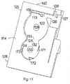
figure 11 montre un schéma du support selon lafigure 2 mais sans les moyens de comptage, - La
figure 12 présente un schéma de la partie intermédiaire de la poutre d'entraînement, - la
figure 13 montre un schéma d'une seconde roue de comptage des moyens de comptage, - La
figure 14 présente un schéma des moyens de numérotation d'une première roue de comptage dans le cadre de cette variante de réalisation, - Les
figures 15a et15b montrent un schéma des moyens de numérotation d'une seconde roue de comptage dans le cadre de cette variante de réalisation, - La
figure 16 présente un exemple de positionnement d'un microcapteur selon cette variante de réalisation sur une structure apte à fléchir, - Les
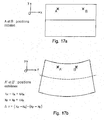
figures 17a et 17b présentent le principe de fonctionnement du microcapteur selon l'invention, - Les
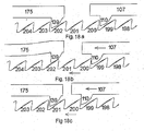
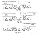
figures 18a à 18e montrent des schémas de différents positionnements successifs des dents d'entraînement et anti-retour par rapport à celles de la première roue de comptage lors de la détection du passage d'un véhicule sur la structure fléchie, - la
figure 19 présente un schéma de l'une des deux faces principales du support d'un microcapteur selon une quatrième variante de réalisation de l'invention, - la
figure 20 présente les moyens de détection et de comptage selon cette variante de réalisation de l'invention, - la
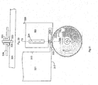
figure 21 présente les moyens de comptage selon cette variante de réalisation de l'invention, - La
figure 22 montre une variante de réalisation d'une partie d'un microcapteur selon lafigure 19 .
- the
figure 1 shows a diagram of one of the two main faces of the support of a microsensor according to a first embodiment of the invention, - the
figure 2 shows a diagram of the other main face of the support of a microsensor as well as counting means according to this variant embodiment, - the
figure 3 presents a simplified diagram of a section according to plane AA 'of thefigure 1 , - the
figure 4 shows more precisely the counting means in this embodiment of the invention, - The
figure 5 presents the deformations undergone by a sensor according to this embodiment of the invention when the structure, to which it is attached, is subjected to a stress, - The
figure 6 more particularly shows counting means according to a second embodiment of the invention, - The
figure 7 presents a diagram explaining the mode of operation of this second embodiment of the invention, - the
figure 8 shows a diagram of one of the two main faces of the support of a microsensor according to a third embodiment of the invention, - the
figure 9 shows a diagram of the other main face of the support of a microsensor as well as counting means according to this variant embodiment, - the
figure 10 shows a simplified diagram of part of the counting means and a non-return device and comprising in particular a first counting wheel, - the
figure 11 shows a diagram of the support according to thefigure 2 but without the counting means, - The
figure 12 presents a diagram of the intermediate part of the driving beam, - the
figure 13 shows a diagram of a second counting wheel of the counting means, - The
figure 14 presents a diagram of the numbering means of a first counting wheel in the context of this variant embodiment, - The
figures 15a and15b show a diagram of the numbering means of a second counting wheel in the context of this variant embodiment, - The
figure 16 shows an example of positioning of a microsensor according to this embodiment variant on a structure able to flex, - The
Figures 17a and 17b present the principle of operation of the microsensor according to the invention, - The
Figures 18a to 18e show diagrams of different successive positioning of the drive and non-return teeth with respect to those of the first counting wheel when detecting the passage of a vehicle on the flexed structure, - the
figure 19 shows a diagram of one of the two main faces of the support of a microsensor according to a fourth embodiment of the invention, - the
figure 20 presents the detection and counting means according to this variant embodiment of the invention, - the
figure 21 presents the counting means according to this variant embodiment of the invention, - The
figure 22 shows an alternative embodiment of a portion of a microsensor according to thefigure 19 .
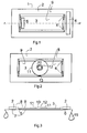
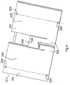
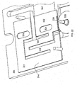
Les
Ce capteur 1 comporte un support S comportant une première partie 2 en forme de cadre et sur laquelle est fixé un premier plot 6 destiné à être fixé sur une structure 15 soumise à des cycles de déformations notamment en traction, en compression ou en flexion par exemple dues à une sollicitation mécanique et/ou thermique.This
Le support S comporte aussi une seconde partie 3, aussi appelé navette dans la suite, de forme rectangulaire et de dimensions plus faibles que l'intérieur dudit cadre 2. Le première et le seconde parties 2, 3 sont solidarisées l'une à l'autre par quatre ressorts 4 disposés dans l'espace libre entre ces deux parties 2, 3 et au niveau de chacun des quatre coins de la seconde partie 3. Cette seconde partie 3 comporte aussi un second plot 5 disposé, dans cet exemple de réalisation, du côté opposé au montant du cadre 2 qui supporte le premier plot 6 et destiné lui aussi à être fixé sur ladite structure 15.The support S also comprises a
Les plots 5 et 6 constituent donc des zones d'ancrage du capteur 1 sur la structure 15 à surveiller. La surface interne 14 du cadre 2 constitue une butée pour la navette 3.The
Comme, montré sur les
Comme montré sur la
Au moins une poutre d'entraînement 20, appelée poutre dans la suite, solidaire de la première partie 2 du support S comporte une dent 21 au niveau de son extrémité libre 22, cette dent 21 étant apte à former un engrenage, de type cliquet, avec celles de ladite roue dentée 11.At least one
Sur cette figure, la direction OX indique la direction des déplacements relatifs de la première partie 2 du support par rapport à la seconde partie 3 aptes à être comptés par les moyens de comptage tandis que la flèche indique le sens normal de rotation de la roue 11 de comptage. Selon cette direction, chacune des dents 16 de cette première roue dentée 11 comporte une première surface radiale 23 et une surface inclinée 24 reliant l'extrémité supérieure 25 de ladite première surface radiale à la base 26 de la surface radiale de la dent suivante. Selon cette même direction, la dent 21 solidaire de la poutre d'entraînement 20 comporte une surface inclinée 27 et une surface radiale 28, cette dernière se trouvant en vis-à-vis avec ladite première surface radiale 23 d'une dent 16 de la première roue 11 de comptage.In this figure, the direction OX indicates the direction of relative displacements of the
Ainsi la dent 21 de la poutre d'entraînement présente une face d'entraînement qui vient en contact avec la dent de la roue de comptage pour tracter cette roue lors d'un déplacement dans un sens de l'élément entraînant et une face de guidage autorisant le glissement, et donc l'escamotage, de l'élément entraînant sur la dent de la roue de comptage lors d'un déplacement dans le sens opposé au précédent de l'élément entraînant.Thus the
La poutre d'entraînement présente une élasticité suffisante pour permettre l'escamotage d'une dent 16 sans détérioration.The driving beam has sufficient elasticity to allow the retraction of a
Comme montré sur la
La différence de coordonnées entre la position initiale et la position extrême est donnée par l'expression suivante : ![]()
![]()
Cette différence d'écartement entre les plots 5 et 6 entraîne une variation de positionnement entre les première et seconde parties, respectivement 2 et 3. Comme la roue dentée 11 est solidaire de la seconde partie 3 et que la poutre d'entraînement 20, dont la dent 21 est engrenée sur la roue dentée 11, est solidaire de la première partie 2 du support S, ladite variation de positionnement produit un entraînement de la roue dentée 11 par la poutre d'entraînement 20 dans le sens de la flèche. Comme, dans cet exemple de réalisation, le déplacement relatif de la dent 21 de la poutre d'entraînement 20 par rapport à la deuxième partie 3 est de l'ordre de grandeur du pas des dents 16 de la roue dentée 11, à savoir, une fois et demi plus grand, la roue dentée 11 va être entraînée en rotation par la dent 21 de la poutre d'entraînement 20, les faces radiales respectives 23 et 28 de la dent n de la roue dentée 11 et de la dent 21 de la poutre d'entraînement 20 étant en contact. A la fin de la sollicitation, ou un certain temps après, les plots, et donc les supports correspondant reviendront dans leur position initiale mais le dispositif anti-retour, constitué des lames 12 et des secondes dents 18 de la roue dentée 11, empêche la roue dentée 11 de tourner dans le sens opposé à celui de la flèche tandis que, de part son élasticité, la face inclinée 27 de la dent 21 de la poutre d'entraînement glisse sur celle de la dent n+1 de la roue dentée 11 avec laquelle elle est en contact jusqu'à dépasser le sommet 25 de cette dent, la face radiale 28 de la dent 21 de la poutre d'entraînement se trouvant alors en regard de la face radiale 23 de la dent n+1 de la roue dentée 11.This spacing difference between the
A l'issue de ce cycle, les plots 5 et 6 sont revenus à leur position initiale tandis que la roue dentée 11 a tourné d'un pas de ses dents 16 dans le sens de la flèche.At the end of this cycle, the
En résumé, l'éloignement des plots 5 et 6, suite à une sollicitation, produit un entraînement de la roue dentée 11 par la dent d'entraînement 21 de la poutre d'entraînement 20 tandis que le rapprochement de ces deux parties, à la fin de la sollicitation, produit un maintien de la première roue dentée 11 par le dispositif anti-retour 12, 19 et un escamotage de la dent 21 de la poutre d'entraînement 20 sur une dent 16 de la première roue dentée 11.In summary, the spacing of the
Ainsi, la détection par le microcapteur d'un cycle de variations de distance se traduit par une rotation de la roue dentée 11, des repères associés à cette roue permettant ensuite de déterminer le nombre de cycles subis par la structure depuis une origine, où entre deux temps donnés.Thus, the detection by the microsensor of a cycle of distance variations results in a rotation of the
Par ailleurs, il ressort de ce qui précède que pour permettre le comptage du nombre de cycles de déformations subis par une structure, il est nécessaire d'avoir une distance L entre les plots déterminée avec précision. C'est pour cette raison qu'il est nécessaire d'avoir des zones d'ancrage de faible dimension dans la direction OX de détection des déformations. Ceci est assuré par la présence des plots 5 et 6 qui permettent un collage de faible épaisseur e dans la direction OX et de hauteur h plus importante selon la direction Y perpendiculaire à OX, la faible épaisseur des plots 5 et 6 permettant de déterminer la dite distance L avec précision tandis que la hauteur h est suffisante pour permettre une bonne résistance du collage du microcapteur sur la structure.Furthermore, it follows from the foregoing that to allow counting the number of deformation cycles experienced by a structure, it is necessary to have a distance L between the studs determined with precision. It is for this reason that it is necessary to have small anchoring zones in the OX direction of deformation detection. This is ensured by the presence of the
Pour permettre un résultat similaire par collage, les plots peuvent aussi être remplacés par des encoches ou par des alésages.To allow a similar result by gluing, the studs can also be replaced by notches or by bores.
En l'absence de zone d'ancrage constituées par des plots, des encoches ou des alésages, lors du placage du microcapteur sur la structure, les plots de colle s'étaleraient de façon aléatoire et la longueur L entre les deux zones d'ancrage pourrait prendre n'importe quelle valeur. Il ne serait donc pas possible de prévoir le fonctionnement du microcapteur pour le comptage des cycles de variations de distance entre deux points A et B d'une structure.In the absence of anchoring zone constituted by studs, notches or bores, during the plating of the microsensor on the structure, the adhesive studs would spread randomly and the length L between the two anchoring zones. could take any value. It would therefore not be possible to predict the operation of the microsensor for counting cycles of distance variations between two points A and B of a structure.
Par ailleurs d'autres modes de fixation que le collage peuvent être envisagés tels que la fixation du microcapteur sur la structure par vis ou par goupille. Pour cela chacun des plots est remplacé par au moins un alésage et préférablement deux alésages positionnés de sorte que leur diamètre d soit très inférieure à la distance D séparant leur axe, par exemple d/D<0,2.Moreover, other methods of attachment than gluing can be envisaged such as the fixing of the microsensor on the structure by screw or pin. For this purpose each of the pads is replaced by at least one bore and preferably two bores positioned so that their diameter d is much smaller than the distance D separating their axis, for example d / D <0.2.
Il peut notamment être envisagé de fixer le capteur à l'aide de goupilles précontraintes Pour cela, le capteur est précontraint en usine par un cadre extérieur qui peut d'ailleurs faire office de packaging du capteur. On réalise d'une part un alésage sur le support, de diamètre légèrement inférieur à celui de la goupille, de façon à garantir un ajustement serré entre la goupille et le support, et, d'autre part, un alésage sur la structure, cette fois-ci de diamètre légèrement supérieur à celui de la goupille pour permettre la mise en place du capteur et le rattrapage du jeu.It can in particular be envisaged to fix the sensor using prestressed pins For this, the sensor is preloaded at the factory by an outer frame that can also act as a packaging sensor. On the one hand, a bore is made on the support, with a diameter slightly smaller than that of the pin, so as to ensure a tight fit between the pin and the support, and, on the other hand, a bore on the structure, this this time slightly larger than the diameter of the pin to allow the installation of the sensor and the catch of the game.
Après fixation sur la structure, avec un gabarit de perçage présentant un entraxe ad hoc, la précontrainte est relâchée. Les génératrices "extérieures" des goupilles viennent alors en contact avec les génératrices des trous préalablement percés dans la structure permettant un rattrapage de jeu.After fixing on the structure, with a drilling template having an appropriate spacing, the prestress is released. The "outer" generators of the pins then come into contact with the generatrices of the holes previously drilled in the structure allowing a catch of play.
Les déplacements induits par la structure sont alors intégralement transférés au capteur.The displacements induced by the structure are then entirely transferred to the sensor.
Naturellement, le signe de la précontrainte peut être inversée si le signe des sollicitations induites par la structure est lui même inversé.Naturally, the sign of the prestressing can be reversed if the sign of the stresses induced by the structure is itself reversed.
Il peut aussi notamment être envisagé de fixer le capteur sur la structure à l'aide de vis. Cette solution implique de réaliser un alésage sur le support, de diamètre légèrement supérieur à celui de la vis, pour permettre son passage, et un taraudage sur la structure pour visser la vis.It can also be considered in particular to fix the sensor on the structure using screws. This solution involves making a bore on the support, of diameter slightly greater than that of the screw, to allow its passage, and a tapping on the structure to screw the screw.
Ce mode de fixation ne nécessite pas obligatoirement de précontrainte. Il exige en revanche d'immobiliser les parties mobiles pendant le serrage des vis car celui-ci peut induire des déplacements parasites par friction. Il peut donc être opportun d'utiliser un capot extérieur de maintien de la forme du capteur. Ce capot immobilise les parties mobiles pendant la pose.This method of attachment does not necessarily require prestressing. It requires, however, to immobilize the moving parts during the tightening of the screws because it can induce parasitic displacements by friction. It may therefore be appropriate use an outer cover to maintain the shape of the sensor. This hood immobilizes moving parts during installation.
Il ressort de ce qui précède que la réalisation de plots, d'encoches ou d'alésage comme zone d'ancrage permet de connaître avec précision la distance L séparant les zones d'ancrage et donc de permettre le comptage des cycles de variations de distance entre deux points A et B d'une structure. Connaissant les caractéristiques de la déformation de la structure, et compte tenu du pas P des dents de la roue de comptage, on détermine la distance L entre les points d'ancrage de sorte que lors de la déformation de la structure, la variation de distance entre les zones d'ancrage 5 et 6 soit supérieure au pas P des dents de la roue de comptage et préférentiellement voisine ou égale à 1,5. P.It follows from the foregoing that the realization of studs, notches or boring as anchoring zone makes it possible to accurately know the distance L separating the anchoring zones and thus to allow the counting of the cycles of variations in distance. between two points A and B of a structure. Knowing the characteristics of the deformation of the structure, and taking into account the pitch P of the teeth of the counting wheel, the distance L between the anchoring points is determined so that during the deformation of the structure, the variation of distance between the anchoring
De cette description, il ressort que d'une part la distance entre les zones d'ancrage doit être déterminée avec précision et d'autre part que le pas de la denture de la première roue d'entrée doit être de l'ordre de grandeur du déplacement relatif desdites parties 2 et 3 du support S. Les techniques traditionnelles permettent de réaliser des dentures de quelques microns mais celles-ci peuvent s'avérer insuffisantes pour capter des déplacements submicroniques. Or, les déplacements relatifs mis en jeu dans des phénomènes de compression mécanique ou de dilatation thermique peuvent être submicroniques.From this description, it appears that on the one hand the distance between the anchoring zones must be determined accurately and on the other hand that the pitch of the toothing of the first input wheel must be of the order of magnitude. the relative displacement of said
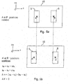
Un principe de subdivision du pas est proposé de manière à pouvoir enregistrer un déplacement relatif inférieur au pas de la denture de la roue dentée, et ce, dans le cadre d'un capteur 30 selon un second mode de réalisation de l'invention. Ce principe permet d'une part d'accroître la sensibilité du capteur puisqu'il permet d'accéder à des niveaux de sensibilité plus grands que la périodicité des motifs géométriques à laquelle la technologie de fabrication permet d'arriver et d'autre part l'utilisation de techniques moins sophistiquées pour la réalisation du composant donc se traduire par un coût de fabrication inférieur et par une meilleure robustesse du capteur. Les
Comme montré sur la
Cette roue dentée 35 comporte des dents 36 sur sa surface périphérique externe 37 et une surface périphérique interne 38 de forme cylindrique.This
Cinq poutres d'entraînement 40, solidaires de la première partie 32 du support S1 et disposées sensiblement parallèlement les unes par rapport aux autres comportent, chacune une dent 41 au niveau de leur extrémité libre 42, ces dents 41 étant disposées entre-elles à une distance multiple du pas P de la denture de la roue plus une fraction de ce pas, à savoir un cinquième de ce pas de sorte que l'une seulement de ces dents constitue un engrenage avec des dents 36 de ladite roue dentée 35. D'une manière générale, l'écartement entre deux dents successives des poutres 40 sera : ![]()
- m est le nombre de poutres,
- I1 et I2 sont des nombres entiers
- P est le pas des dents 36 de la roue 35

- m est le nombre de poutres,
- I1 et I2 sont des nombres entiers naturels et :

- m is the number of beams,
- I 1 and I 2 are integers
- P is the pitch of the
teeth 36 of the wheel 35 - m is the number of beams,
- I 1 and I 2 are natural whole numbers and:
Et préférentiellement, pour permettre une indexation en vernier, I2 ≠ m.And preferably, to allow indexing vernier, I 2 ≠ m.
Sur cette figure, la direction OX', opposée à OX, indique la direction des mouvements ou déplacements relatifs de la première partie 32 du support par rapport à la seconde partie 33 aptes à être comptés par les moyens de comptage tandis que la flèche indique le sens normal de rotation de la roue 35 de comptage. Selon cette direction, chacune des dents 36 de cette première roue dentée 11 comporte une première surface radiale 43 et une surface inclinée 42 reliant l'extrémité supérieure 44 de ladite première surface radiale à la base 48 de la surface radiale 43 de la dent suivante. Selon cette même direction, chacune des dents 41 solidaires de la poutre d'entraînement 40 comporte une surface inclinée 46 et une surface radiale 45, cette dernière se trouvant, pour l'une des dents 41, en vis-à-vis à face avec ladite première surface radiale 43 d'une dent 36 de la première roue 35 de comptage.In this figure, the direction OX ', opposite to OX, indicates the direction of movements or relative displacements of the
Les poutres d'entraînement 40 présentent une élasticité suffisante pour permettre l'escamotage de leur dent 41 sur une dent 36 de la première roue 35 de comptage, et ce, sans détérioration.The drive beams 40 have sufficient elasticity to allow the retraction of their
La surface périphérique interne 38 de la roue dentée 35 et l'extrémité des dites lames 39 sont destinées à coopérer pour former un moyen d'accommodation élastique de la roue dentée 35 sur le moyeu 34, la force de frottement de l'extrémité des lames 39 sur la surface périphérique interne 38 de la roue 35 étant, d'une part, supérieure à celle que peuvent engendrer les poutres d'entraînement lorsqu'elles sont dirigées dans une première direction OX, entraînant alors un glissement des dents 41 des poutres 40 sur la roue 35 et, d'autre part, inférieure à celle que peuvent engendrer les poutres d'entraînement lorsqu'elles sont dans une seconde direction OX', opposée à ladite direction OX, entraînant alors un glissement de la surface périphérique interne 38 de la roue 35 sur les extrémités des lames 39. Le glissement de la roue sur les extrémités des lames 39 est autorisé par un dimensionnement correct du moyen d'accommodation élastique du couple résistant par rapport au cisaillement possible de la dent 41 de la poutre 40 ou de celle, 36, de la roue dentée 35.The inner
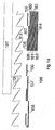
La
Les différentes phases sont respectivement numérotées de 1 à 5 et de A à E.The different phases are respectively numbered from 1 to 5 and from A to E.
Dans la phase A, la roue dentée 35 s'est déplacée par rapport aux poutres 40 fixes. La poutre 3 franchit la dent représentée en sombre de la roue dentée 35, et de part la configuration géométrique des dentures, interdit le retour de la dent, les poutres 40 étant représentées sur ce premier schéma juste avant le passage de la dent pour bien identifier les séquences, au lieu de les représenter après le franchissement. Les poutres 4 et 5 sont mises en flexion par la denture. Les poutres 1 et 2 seront également mises en flexion lors du prochain déplacement relatif de la roue.In phase A, the
L'application du cycle de chargement suivant de la phase B provoque, un deuxième déplacement relatif de la première roue par rapport aux poutres fixes. Cette fois ci, c'est la poutre 4 qui se retrouve à passer une autre dent de la roue dentée 35 et à interdire le retour de cette roue en un autre point de la denture de la roue que celui de la phase A.Applying the next loading cycle of phase B causes a second relative displacement of the first wheel relative to the fixed beams. This time, it is the
De même, lors de la phase C, la poutre 5 vient de franchir la denture de la roue et interdit son retour en autre endroit que celui de la phase B. Il en est de même des phases D et E.Similarly, during phase C, the
Lors de la prochaine phase A, la poutre 3 franchit de nouveau une dent de la roue dentée. Cette dent est celle qui est consécutive à celle représentée en sombre sur tous les schémas. Par conséquent, les cinq cycles de sollicitation se sont traduits au niveau de la première roue par l'engrènement d'une dent, illustrant le principe de subdivision du pas, donc la possibilité de détecter et d'enregistrer une information avec une résolution supérieure à celle intrinsèque du système.In the next phase A, the
Un tel dispositif permet de détecter et de compter des cycles de variations de distance inférieures à 5µm. En augmentant le nombre de poutres, des variations de distances inférieures à 1µm peuvent être détectées et comptées.Such a device makes it possible to detect and count cycles of distance variations of less than 5 μm. By increasing the number of beams, variations of distances smaller than 1 μm can be detected and counted.
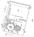
Les
Les
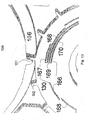
Selon ce mode de réalisation, un microcapteur passif de détection et de comptage du nombre de passage de véhicules comprend un support 101, principalement en forme de U comportant ainsi une première partie 102 et une deuxième partie 103 reliées entre-elles par une troisième partie 104 constituant la base du U, et des moyens de comptage 105 disposés sur le support et comportant au moins une première roue dentée 106 disposée sur ladite première partie 102 du support 101 et, d'une part, une poutre d'entraînement 107 de cette première roue dentée 106 fixée, à l'une, 108, de ses extrémités 108, 109, à ladite deuxième partie 103 et comportant, à son autre extrémité 109, une dent 110, montrée sur la
Comme montré sur la
Dans cet exemple de réalisation, les premières et secondes zones d'ancrage 224, 225 sont disposées respectivement selon un premier axe Y1 et un second axe Y2 parallèles entre eux et séparés par une distance L. D'une manière préférentielle permettant de réduire au minimum la taille du capteur, ces zones d'ancrages sont disposées de telle sorte que la longueur L soit la plus grande possible et de telle sorte que la déformation de la structure entre les axes Y1 et Y2 soit au moins égale à P. En effet, lorsque le microcapteur est fixé sur une structure soumise à une déformation, la variation de distance entre les deux zones d'ancrage 224 et 225, donc entre les axes Y1 et Y2 est proportionnelle à cette longueur L. Par conséquent, pour un pas P donné des dents de la roue de comptage, et dans le cas de l'utilisation d'une seule poutre d'entraînement, la déformation de la structure entre les axes Y1 et Y2 doit au moins être égale à P et préférentiellement inférieure ou égale à 1,5.P.In this embodiment, the first and
Comme montré sur la
Dans cet exemple de réalisation la troisième partie 104 du support a elle-même une forme de U inversé avec une base 136 épaisse. Cette forme permet d'avoir des sections plus petites au niveau des branches du U de cette poutre que de la base 136 et dans le cas où une force importante était exercée au niveau de cette troisième partie une cassure surviendrait au niveau de l'une des branches et donc dans une direction parallèle à celle du déplacement normal des premières et secondes parties, ce qui permet d'éviter tout déplacement relatif entre ces parties dans la direction normale du déplacement et d'éviter un éventuel décalage entre la roue dentée 106 et la dent 110 de la poutre d'entraînement 107.In this embodiment, the
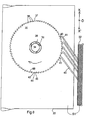
Sur la
Cette première roue dentée 106 comporte 512 dents soit 29.This
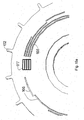
La
La première gravure 120 est disposée dans la partie supérieure 125 de la première partie et du côté de la première partie 102 du support. Elle a la forme d'un U à base épaisse et l'une des branches 126 est plus longue que l'autre 127.The
La seconde gravure 121 est de forme rectangulaire allongée et disposée dans la continuité de la première et en direction du côté opposé à la troisième partie 104 du support 101. Toutefois, cette gravure n'est pas complète car il reste un dispositif anti-retour 113 disposé longitudinalement sur moins de la moitié de la longueur de la gravure et fixé à la première partie 102 du support 101 par son extrémité située au niveau du côté transversal 170 de la gravure qui est à l'opposé de la première gravure 120.The
La troisième gravure 122 est de forme cylindrique et disposée dans la continuité de la seconde et en dessous, c'est-à-dire en direction de la partie basse 128 de la première partie 102 du support 101. Toutefois, la gravure n'est pas complète car il reste une partie centrale cylindrique 129. Cette gravure 122 est destinée à recevoir la première roue de comptage 106 et son diamètre est légèrement supérieur à celui de cette dernière. De plus, la première roue de comptage 106 comporte un alésage central et la partie centrale cylindrique 129 constitue un axe pour cette première roue dentée 106.The
La quatrième gravure 123 est de forme rectangulaire et comporte une partie inférieure 31 de la troisième gravure 122 et une partie supérieure 132 de la cinquième gravure 124.The
La cinquième gravure 124 est de forme cylindrique de diamètre légèrement inférieur à celui de la troisième gravure 122 et disposée tangentiellement à cette dernière et dans la direction de la partie inférieure 128 de cette première partie 123 du support. Cette gravure 124 est destinée à recevoir une seconde roue dentée de comptage 130 et n'est pas complète car il reste d'une part une partie centrale cylindrique destinée à servir d'axe de rotation 155 à la seconde roue dentée de comptage 130 et d'autre part trois poutres 171, 172 et 173 disposées respectivement à π/2 Rd et aptes à maintenir en position et à servir de dispositif anti-retour à la seconde roue dentée 30. Cette dernière comporte 16 dents soit 24.The
La
- la première roue dentée 106 disposée sur l'axe 129,
- la poutre d'entraînement 107 solidaire de la deuxième partie 103 du support 101 et comportant une
dent 110 apte à constituerun engrenage 111 avec celles 112, de la première roue dentée 106, - un dispositif anti-retour 113 de la première roue dentée 106 constituée
par une poutre 175 solidaire par l'une de ses extrémités 137 de la première partie 102 du support 101 et comportant, àson autre extrémité 138une dent 139 apte à constituer un engrenage avec celles, 112, de la première roue dentée 106. La flèche indiquant le sens normal de rotation de la première roue dentée de comptage 106,la dent 139 du dispositif anti-retour comporte, selon cette direction,une surface inclinée 140 et unesurface radiale 141,la surface radiale 140 se trouvant en face à face avec une surfaceradiale d'une dent 112 de la première roue dentée 106.
- the
first gear 106 disposed on theaxis 129, - the
driving beam 107 integral with thesecond portion 103 of the support 101 and comprising atooth 110 capable of constituting agear 111 with those 112, of thefirst gear wheel 106, - a
non-return device 113 of thefirst gear wheel 106 constituted by abeam 175 secured by one of itsends 137 of thefirst portion 102 of the support 101 and having at its other end 138 atooth 139 adapted to constitute a gear with those, 112, of the firsttoothed wheel 106. The arrow indicating the normal direction of rotation of thefirst counting gear 106, thetooth 139 of the non-return device comprises, in this direction, aninclined surface 140 and asurface radial 141, theradial surface 140 being in face to face with a radial surface of atooth 112 of thefirst gear wheel 106.
Comme montré sur cette figure, la poutre d'entraînement 107 et celle, 75, du dispositif anti-retour sont mises en précontrainte en flexion sur la roue dentée 106 de par leur positionnement. En effet l'extrémité des dents n'est pas tangentielle à la base des dents de la première roue dentée 106 mais tangentielle à une position située plus proche de l'axe de cette roue, Comme ces poutres ne peuvent aller au-delà de ladite base, elles sont automatiquement soumises à ladite précontrainte exercée par la première roue dentée 106.As shown in this figure, the
La
Cette partie intermédiaire 143 est en forme de U dont la base 144, et les deux branches 145, 146 ont sensiblement la même épaisseur, l'une, 145 ,des branches étant plus longue que l'autre et destinée à pénétrer dans la partie plus longue de la branche 126 de la première gravure du premier support 101 et qui, comme on peut le voir sur cette figure, comporte deux butées 147, 148 faisant chacune face à l'un des côté de la partie plus longue 149 de la branche 145 de la poutre d'entraînement.This
La fonction de ces excroissances est de limiter le déplacement de la poutre d'entraînement en direction de la première partie du support, d'une valeur calibrée et correspondant sensiblement à la valeur d'un pas et demi des dents 112 de la première roue dentée 106. Ces excroissances constituent ainsi des moyens de limitation de course de la dent 110 de la poutre d'entraînement 107, ou, en d'autres termes, des butées.The function of these protrusions is to limit the displacement of the drive beam towards the first part of the support, a calibrated value and corresponding substantially to the value of a step and a half of the
On constate par ailleurs que l'épaisseur de la poutre d'entraînement au delà de cette partie intermédiaire est d'abord équivalente à celle de cette partie puis plus faible jusqu'à son extrémité comportant la dent d'entraînement 110, cette faible épaisseur étant apte à lui assurer une élasticité suffisante pour permettre l'entraînement de la roue dentée 106 par la dent d'entraînement 110 dans un sens aller et l'escamotage de cette dent 110 d'entraînement sur celles, 112, de la première roue dentée 106 dans le sens retour.Furthermore, it can be seen that the thickness of the driving beam beyond this intermediate portion is initially equivalent to that of this portion and then lower to its end comprising the driving
Comme montré sur les
Comme montré sur la
Cette troisième roue dentée de comptage 150 comporte une seule dent 151 en forme d'arche gothique apte à constituer un engrenage avec celles 152, en forme d'arche romane, de la seconde roue de comptage 130, ces deux roues 130, 150 ayant la même épaisseur et étant disposées dans un même plan. Cette troisième roue dentée 150 est disposée dans la quatrième gravure 123 de la première partie 102 du support 101 et comporte un alésage de diamètre sensiblement égale à l'axe 155 émergeant de la quatrième gravure. La longueur des dents 152 et 151 des seconde et troisième roues dentées 130 et 150 est telle que lorsque la dent 51 de la troisième roue dentée 150 entre en contact avec une dent 152 de la seconde roue dentée 130, ce contact perdure sur une longueur sensiblement égale au pas des dents 152 de la seconde roue dentée 130.This third
Des moyens de lecture optiques de type lecteur de codes barres sont associés aux moyens de comptage afin de faciliter la lecture.Bar code reader optical reading means are associated with the counting means in order to facilitate reading.
Comme montré sur la
Comme montré sur la
Pour effectuer la lecture du nombre de passages de véhicule entre un temps t0 et un temps t1, on effectue une lecture optique de la numérotation des dents sur chacune des première et seconde roues dentées 106 et 130 à l'instant to puis à l'instant t1, le lecteur ayant la même position à ces deux instants. L'image de la première lecture au temps t0 est celle de référence qui permet de déterminer quelle dent était engagée au moment de l'installation du dispositif. La deuxième image sert à identifier la dent engagée au moment t1, choisi par l'opérateur. L'identification de la dent engagée peut se faire de manière automatisée en important les deux images dans un logiciel de traitement d'images en générant un masque 177 délimitant les zones de lecture comme montré sur les
Tous les éléments de ce microcapteur sont réalisés en silicium ce qui lui permet de fonctionner correctement qu'elle que soit sa température de fonctionnement puisque les dilatations ou les constrictions qui en résultent seront les mêmes dans toutes les direction pour tous les composants.All elements of this microsensor are made of silicon which allows it to work properly regardless of its operating temperature since the resulting dilations or constrictions will be the same in all directions for all components.
Le fonctionnement du dispositif décrit précédemment est le suivant :
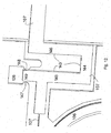
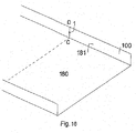
- Il est tout d'abord fixé, comme montré sur la
figure 16 , par exemple avec de la colle et par ses surfaces planes 133 et 134 des premières et secondes parties du support 101 sur le parapet 181d'un pont 100 comportant une chaussée 180 sur laquelle circule des véhicules.
- It is first fixed, as shown on the
figure 16 , for example with glue and by itsplane surfaces 133 and 134 of the first and second parts of the support 101 on theparapet 181 of abridge 100 having aroadway 180 on which vehicles circulate.
Ce microcapteur est positionné sur le parapet de part et d'autre d'une droite virtuelle CD verticale. Pour une position donnée du capteur sur le parapet, le microcapteur ne comptera le passage du véhicule en fonction d'une valeur seuil correspondant à la masse du véhicule. Il sera ainsi par exemple possible de détecter, avec trois capteurs identiques mais disposés à des endroits différents du parapet, le nombre de véhicule passant d'une masse supérieure à 500kg pour l'un, le nombre de véhicule de plus de 3500kg pour le second et tous les véhicules de plus de 10000kg pour l'autre.This microsensor is positioned on the parapet on either side of a virtual straight line CD. For a given position of the sensor on the parapet, the microsensor will not count the passage of the vehicle according to a threshold value corresponding to the mass of the vehicle. It will thus be possible for example to detect, with three identical sensors but arranged at different places of the parapet, the number of vehicle passing from a mass greater than 500kg for one, the number of vehicle of more than 3500kg for the second. and all vehicles over 10,000kg for each other.
Comme montré sur les
Dans le cadre de l'exemple de réalisation précité, c'est la différence de déplacement des points A et B selon l'axe Ox, à savoir Δx = (xA'-xA) - (xB'-xB) qui est mise en jeu pour actionner les moyens passifs de comptage, le point A se trouvant sur la première partie 102 du support 101 et la point B se trouvant sur la seconde partie 103 du support 101. Ainsi, Δx est supérieur au pas des dents 112 de la première roue dentée 106 et préférablement inférieur à 2 fois ce pas. Dans tous les cas, les butées 147, 148 sont aptes à limiter le déplacement de la première partie du support 101 par rapport à le second partie d'une distance Δx, par rapport à leur position de repos, supérieure au pas des dents 112 de la première roue 106, mais inférieure à deux fois ce pas.In the context of the aforementioned embodiment, it is the difference in displacement of the points A and B along the Ox axis, namely Δx = (x A ' -x A ) - (x B' -x B ) which is used to actuate the passive counting means, the point A being on the
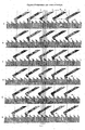
Les
Sur la
Lorsqu'un véhicule commence à passer sur la chaussée 180 à la droite de la droite CD, les première et seconde parties 102, 103 du support 101 commencent à se rapprocher comme montré sur la
A cet instant, soit naturellement, soit du fait des butées 147 et 148, ledit rapprochement s'arrête et l'on constate que la dent 200 de la roue dentée a pris la position initiale de la dent 201, la roue 106 ayant donc tourné d'une distance sensiblement égale à un pas des dents de cette roue 106.At this moment, either naturally or because of
Lorsque le véhicule a dépassé la droite de la droite CD, les première et seconde parties 102, 103 du support 101 commencent à s'éloigner pour revenir à leur position de repos. La face inclinée de la dent d'entraînement va entrer en contact avec la face inclinée de la dent 199 et commencer à faire tourner la première roue dentée 106 dans le sens inverse à la flèche et ce jusqu'à ce que la face radiale de la dent anti-retour 139 entre en contact avec la face radiale de la dent 202. A cet instant le dispositif anti-retour va empêcher toute rotation supplémentaire de la première roue dentée 106 dans le sens opposé à celui de la flèche. Comme montré sur la
A la fin de ce cycle, montré sur la
La
Les première et seconde encoches sont destinées à recevoir de la colle afin de fixer le support 301 sur la structure d'accueil et d'obtenir ainsi des zones fixes de faible largeur et situées à des endroits prédéterminés et permettant un fonctionnement optimal du capteur.The first and second notches are intended to receive glue in order to fix the
Deux plots cylindriques 311, 312 sont chacun fixés dans un alésage pratiqué dans la deuxième partie du support. Leur fonction est de guider le positionnement d'une plaque 314, réalisée ici en silicium et de forme carrée. Cette plaque comporte une ouverture 315 en forme de L dont l'une de ses extrémités 316 débouche vers le milieu d'un premier côté 317 du carré tandis que son autre extrémité 318 se trouve au niveau du milieu d'un second côté 319 du carré adjacent audit premier côté 317 mais sans déboucher sur ce second côté de sorte qu'une fine largeur de matière 320 subsiste à ce niveau. Ainsi, cette plaque est constituée par une première et une seconde partie, respectivement 321 et 322, seconde partie dont la largeur est sensiblement égale à celle de la partie intermédiaire 307 de la troisième partie 306 et destinée à être fixée sur cette dernière.Two
Chacune des première et seconde parties 321, 322 de la plaque comporte une ouverture 324 de forme oblongue disposée d'axe transversale confondu avec l'axe Y2 de fixation de la deuxième partie 304 du support 301 selon ledit axe Y2 comme montré sur la
Comme montré sur la
Comme montré sur la
Avec un tel capteur, une déformation de la structure d'accueil dans la direction X produit une déformation similaire du support du capteur donc un éloignement (ou un rapprochement) des axes Y1 et Y2. Cet éloignement (ou ce rapprochement) produit un déplacement relatif de la première partie du support par rapport à la seconde partie et donc un déplacement de la dent 330 de la poutre d'entraînement 329 solidaire de la première partie 302 du support 301 par rapport à la roue dentée 328, ce déplacement produisant un entraînement de la roue dentée 328 dans le sens indiqué par la flèche. Lors du retour de la structure d'accueil dans sa position initiale, du fait de la présence du patin 335 et des formes des dents de la poutre d'entraînement 329 et de la roue dentée 328, la dent 330 de la poutre d'entraînement 329 escamote celle de la roue dentée, cette dernière restant ainsi dans la position prise à l'issue de la rotation dans le sens de la flèche, d'où l'analogie avec un cliquet.With such a sensor, a deformation of the host structure in the X direction produces a similar deformation of the sensor support, thus a distance (or approximation) of the axes Y1 and Y2. This distance (or this approximation) produces a relative displacement of the first part of the support relative to the second part and therefore a displacement of the tooth 330 of the
Dans le cas où le matériau du support serait différent de celui de la structure d'accueil, la compensation de la température peut être effectuée en adaptant la longueur de la première partie du support et/ou de ladite partie intermédiaire de sorte que le produit de la distance séparant les deux axes de collage Y1 ,Y2 du capteur sur la structure d'accueil par le coefficient de dilatation du matériau constitutif de la structure d'accueil soit égal au produit de la distance séparant ledit axe Y1 de collage à la dent de la poutre d'entraînement par le coefficient de dilatation thermique du support du capteur.In the case where the material of the support is different from that of the host structure, the compensation of the temperature can be carried out by adapting the length of the first part of the support and / or of said intermediate part so that the product of the distance separating the two bonding axes Y1, Y2 of the sensor on the receiving structure by the coefficient of expansion of the material constituting the receiving structure is equal to the product of the distance separating said Y1 axis of bonding to the tooth of the driving beam by the coefficient of thermal expansion of the sensor support.
Par ailleurs, en plaçant plusieurs capteurs identiques à des hauteurs différentes de la surface latérale du parapet, il est possible de discriminer les types de véhicule passant sur le pont en fonction de leur masse. A titre d'exemple, un premier capteur positionné le plus bas pourra compter le passage de tous les véhicules dont la masse est supérieure à 500kg, un second capteur placé dans une position intermédiaire pourra compter le passage de tous les véhicules de plus de 3 tonnes et un troisième capteur situé encore plus haut ne comptera le passage que des véhicules de plus de 10 tonnes.Moreover, by placing several identical sensors at different heights of the lateral surface of the parapet, it is possible to discriminate the types of vehicle passing on the bridge according to their mass. For example, a first sensor positioned the lowest can count the passage of all vehicles whose mass is greater than 500kg, a second sensor placed in an intermediate position can count the passage of all vehicles over 3 tons and a third sensor located even higher will only count the passage of vehicles over 10 tons.
La
Les modes de réalisation précédemment décrits présentent, par rapport à l'état de la technique, de nombreux avantages. Ainsi, le microcapteur est totalement passif, et c'est l'événement lui-même (action d'un objet apte à fléchir une structure) qui fourni l'énergie nécessaire à l'activation des fonctions de détection et de comptage.The previously described embodiments have numerous advantages over the state of the art. Thus, the microsensor is totally passive, and it is the event itself (action of an object capable of bending a structure) that provides the energy necessary to activate the detection and counting functions.
Dans le cas présent, le microcapteur est mis en service pour une durée qui n'est pas limitée par la durée de vie de la source d'énergie. Compte tenu de la nature même des matériaux utilisés, en l'occurrence du silicium, l'espérance de vie du capteur est dans tous les cas très supérieure à celle de tous les systèmes d'arme y compris pour des systèmes passifs stockés pour de très longues périodes.In this case, the microsensor is put into operation for a time that is not limited by the life of the energy source. Given the nature of the materials used, in this case silicon, the life expectancy of the sensor is in all cases much greater than that of all weapon systems, including passive systems stored for very short periods of time. long periods.
Dans le cas présent, le caractère inerte du compteur permet d'envisager de l'appliquer sur un système fonctionnant en sécurité pyrotechnique, ce qui procure une avancée considérable par rapport aux capacités actuelles. De plus, un microcapteur selon l'invention est totalement insensible aux champs électromagnétiques.In this case, the inert nature of the meter makes it possible to consider applying it to a system operating in pyrotechnic security, which provides a considerable advance over the current capabilities. In addition, a microsensor according to the invention is totally insensitive to electromagnetic fields.
En outre, la solution proposée est très simple à mettre en oeuvre et son fonctionnement très fiable. Il est indépendant d'une source d'énergie, discret, et d'un coût unitaire faible.In addition, the proposed solution is very simple to implement and its operation very reliable. It is independent of a source of energy, discreet, and a low unit cost.
Par ailleurs, lorsque les moyens de comptage comporte plusieurs poutres aptes à entraîner, successivement, la roue dentée selon une même direction, ces poutres peuvent être disposées du même côté de la roue dentée comme sur la
En outre, la dent de la poutre anti-retour telle que montré sur la
Par ailleurs, dans le cas où l'on souhaite compenser les différences de dilatations thermiques entre le capteur et la structure, il est, d'une part, préférable de réaliser les supports du capteur en une matière dont le coefficient de dilatation thermique est proche de celui du matériau de la structure, et, d'autre part, de compenser géométriquement, via la forme des dites première et seconde partie du support et le positionnement de la roue de comptage, cette dilatation thermique.Moreover, in the case where it is desired to compensate for the differences in thermal expansion between the sensor and the structure, it is, on the one hand, preferable to produce the sensor supports in a material whose thermal expansion coefficient is close of that of the material of the structure, and, secondly, to compensate geometrically, via the shape of said first and second part of the support and the positioning of the counting wheel, this thermal expansion.
Claims (11)
Applications Claiming Priority (1)
| Application Number | Priority Date | Filing Date | Title |
|---|---|---|---|
| FR0703754A FR2916843A1 (en) | 2007-05-29 | 2007-05-29 | MICROSCOPTER FOR DETECTING DISTANCE VARIATION OR CYCLE OF DISTANCE VARIATIONS BETWEEN TWO POINTS OR ZONES OF A STRUCTURE DURING SOLICITATION. |
Publications (4)
| Publication Number | Publication Date |
|---|---|
| EP1998145A2 true EP1998145A2 (en) | 2008-12-03 |
| EP1998145A3 EP1998145A3 (en) | 2013-06-19 |
| EP1998145B1 EP1998145B1 (en) | 2019-03-27 |
| EP1998145B8 EP1998145B8 (en) | 2019-06-26 |
Family
ID=38935777
Family Applications (2)
| Application Number | Title | Priority Date | Filing Date |
|---|---|---|---|
| EP08290493.9A Active EP1998145B8 (en) | 2007-05-29 | 2008-05-28 | Microsensor capable of detecting a distance change or a series of distance changes between two points or zones of a structure when placed under stress |
| EP08290492.1A Active EP1998144B8 (en) | 2007-05-29 | 2008-05-28 | Device for transmitting to a first mobile element comprising teeth, a relative movement between second and third elements of a system |
Family Applications After (1)
| Application Number | Title | Priority Date | Filing Date |
|---|---|---|---|
| EP08290492.1A Active EP1998144B8 (en) | 2007-05-29 | 2008-05-28 | Device for transmitting to a first mobile element comprising teeth, a relative movement between second and third elements of a system |
Country Status (4)
| Country | Link |
|---|---|
| EP (2) | EP1998145B8 (en) |
| DK (2) | DK1998145T3 (en) |
| ES (2) | ES2737424T3 (en) |
| FR (3) | FR2916843A1 (en) |
Cited By (3)
| Publication number | Priority date | Publication date | Assignee | Title |
|---|---|---|---|---|
| FR2974410A1 (en) * | 2011-04-22 | 2012-10-26 | France Etat | PASSIVE AND REVERSIBLE DEFORMATION SENSOR |
| FR3048500A1 (en) * | 2016-03-02 | 2017-09-08 | Etat Francais Represente Par Le Delegue General Pour L'armement | DEFORMATION SENSOR PERMITTING DISCRIMINATION OF MEASUREMENT ACCORDING TO THE DIRECTION OF THE DEFORMATION |
| US10654564B2 (en) | 2016-12-15 | 2020-05-19 | Safran Landing Systems Uk Ltd | Aircraft assembly including deflection sensor |
Families Citing this family (3)
| Publication number | Priority date | Publication date | Assignee | Title |
|---|---|---|---|---|
| WO2010095008A1 (en) * | 2009-02-18 | 2010-08-26 | Aktiebolaget Skf | Contactless sensor and detecting assembly comprising such a contactless sensor |
| FR3008179B1 (en) | 2013-07-02 | 2015-06-12 | France Etat | PASSIVE MICROSCOPTER AND REVERSIBLE DEFORMATION |
| FR3025599B1 (en) | 2014-09-10 | 2019-05-31 | Direction Generale De L'armement -Ds/Sdpa/Bpi - Dga/Ds/Sdpa/Bpi | METHOD FOR COUNTING EVENTS DURING TIME T AND MECHANICAL COUNTERS OF ASSOCIATED EVENTS |
Citations (3)
| Publication number | Priority date | Publication date | Assignee | Title |
|---|---|---|---|---|
| US5452335A (en) | 1992-12-31 | 1995-09-19 | Symbiosis Corporation | Temperature cycle counter |
| US6617963B1 (en) | 1999-02-26 | 2003-09-09 | Sri International | Event-recording devices with identification codes |
| FR2875324A1 (en) | 2004-09-13 | 2006-03-17 | Parifex | Motor vehicles ` e.g. gasoline vehicle, passage detecting and counting system, has filters filtering signals received by microphone and amplified by amplifier, and computing equipment interrogating system to know vehicles` passage and flow |
Family Cites Families (4)
| Publication number | Priority date | Publication date | Assignee | Title |
|---|---|---|---|---|
| FR703754A (en) | 1930-10-16 | 1931-05-06 | Manuf De Machines Modernes | Improvements in the assembly of cliché cylinders in printing machines |
| CH497725A (en) * | 1962-01-31 | 1964-12-31 | Straumann Inst Ag | Drive for a timing device driven by audio-frequency, translational oscillations |
| FR2893139B1 (en) * | 2005-09-13 | 2008-08-08 | France Etat | MICRO SENSOR FOR DETECTION AND DETECTION OF SHOCKS OR ACCELERATIONS / DECELERATIONS. |
| FR2890748A1 (en) * | 2005-09-13 | 2007-03-16 | France Etat Armement | Micro sensor for detecting and calculating e.g. shocks, has passive shock calculating unit associated to displacement unit, and inertial mass and passive unit`s toothed wheel concentrically disposed to engage tooth with toothed wheel |
-
2007
- 2007-05-29 FR FR0703754A patent/FR2916843A1/en active Pending
-
2008
- 2008-05-28 ES ES08290492T patent/ES2737424T3/en active Active
- 2008-05-28 DK DK08290493.9T patent/DK1998145T3/en active
- 2008-05-28 EP EP08290493.9A patent/EP1998145B8/en active Active
- 2008-05-28 ES ES08290493T patent/ES2729924T3/en active Active
- 2008-05-28 DK DK08290492.1T patent/DK1998144T3/en active
- 2008-05-28 EP EP08290492.1A patent/EP1998144B8/en active Active
- 2008-05-29 FR FR0802917A patent/FR2916882A1/en active Pending
- 2008-05-29 FR FR0802916A patent/FR2916844A1/en active Pending
Patent Citations (3)
| Publication number | Priority date | Publication date | Assignee | Title |
|---|---|---|---|---|
| US5452335A (en) | 1992-12-31 | 1995-09-19 | Symbiosis Corporation | Temperature cycle counter |
| US6617963B1 (en) | 1999-02-26 | 2003-09-09 | Sri International | Event-recording devices with identification codes |
| FR2875324A1 (en) | 2004-09-13 | 2006-03-17 | Parifex | Motor vehicles ` e.g. gasoline vehicle, passage detecting and counting system, has filters filtering signals received by microphone and amplified by amplifier, and computing equipment interrogating system to know vehicles` passage and flow |
Cited By (7)
| Publication number | Priority date | Publication date | Assignee | Title |
|---|---|---|---|---|
| FR2974410A1 (en) * | 2011-04-22 | 2012-10-26 | France Etat | PASSIVE AND REVERSIBLE DEFORMATION SENSOR |
| WO2012143627A1 (en) | 2011-04-22 | 2012-10-26 | ÉTAT FRANÇAIS représenté par LE DÉLÉGUÉ GÉNÉRAL POUR L'ARMEMENT | Passive, reversible deformation sensor |
| US9140584B2 (en) | 2011-04-22 | 2015-09-22 | Etat Francais Represente Par Le Delegue General Pour L'armement | Passive, reversible deformation sensor |
| FR3048500A1 (en) * | 2016-03-02 | 2017-09-08 | Etat Francais Represente Par Le Delegue General Pour L'armement | DEFORMATION SENSOR PERMITTING DISCRIMINATION OF MEASUREMENT ACCORDING TO THE DIRECTION OF THE DEFORMATION |
| WO2017149211A1 (en) | 2016-03-02 | 2017-09-08 | Etat Français Represente Par Le Delegue General Pour L'armement | Strain sensor with measurement discrimination according to the deformation direction |
| US10704883B2 (en) | 2016-03-02 | 2020-07-07 | Etat Français Represente Par Le Delegue General Pour L'armement | Strain sensor with measurement discrimination according to the deformation direction |
| US10654564B2 (en) | 2016-12-15 | 2020-05-19 | Safran Landing Systems Uk Ltd | Aircraft assembly including deflection sensor |
Also Published As
| Publication number | Publication date |
|---|---|
| FR2916844A1 (en) | 2008-12-05 |
| FR2916843A1 (en) | 2008-12-05 |
| EP1998144A3 (en) | 2013-10-30 |
| ES2737424T3 (en) | 2020-01-14 |
| FR2916882A1 (en) | 2008-12-05 |
| DK1998144T3 (en) | 2019-07-29 |
| EP1998145B1 (en) | 2019-03-27 |
| EP1998145B8 (en) | 2019-06-26 |
| EP1998144B1 (en) | 2019-05-01 |
| EP1998144A2 (en) | 2008-12-03 |
| EP1998145A3 (en) | 2013-06-19 |
| EP1998144B8 (en) | 2019-06-26 |
| DK1998145T3 (en) | 2019-06-24 |
| ES2729924T3 (en) | 2019-11-07 |
Similar Documents
| Publication | Publication Date | Title |
|---|---|---|
| EP1998145B1 (en) | Microsensor capable of detecting a distance change or a series of distance changes between two points or zones of a structure when placed under stress | |
| EP1056985B1 (en) | Tensile testing sensor for measuring mechanical jamming deformations on first installation and automatic calibrating based on said jamming | |
| EP1599766B1 (en) | Method of producing a mems device | |
| EP2801868B1 (en) | Escapement wheel | |
| EP3766830B1 (en) | Mechanical link for mechanical mems and nems structure, and mems and nems structure comprising such a mechanical link | |
| EP2705330B1 (en) | Passive, reversible deformation sensor | |
| EP3242168A1 (en) | Electromechanical clock movement comprising a device for detecting the angular position of a wheel | |
| EP3017278B1 (en) | Amplified passive and reversible micro-sensor of deformations | |
| EP3423780B1 (en) | Strain sensor with measurement discrimination according to the deformation direction | |
| EP3306416B1 (en) | Mechanical clock movement with power-reserve detection | |
| CA2478960A1 (en) | Strain-measuring device | |
| EP2802852B1 (en) | Passive indexing of a movable element having teeth | |
| FR2893139A1 (en) | Silicon microsensor for e.g. weapon, has inertial mass and toothed wheel disposed in concentric manner such that tooth engages with toothed wheel, and elastic anchoring device limiting rotation of toothed wheel during detection of shock | |
| EP1771741B1 (en) | Device and method for testing at least one conducting joint forming an electrical connection between an electric component and a printed circuit | |
| CH715505A1 (en) | Micromechanical device with local electromagnetic actuation. | |
| EP3982203B1 (en) | Timepiece escapement with semi-direct pulse | |
| FR2890748A1 (en) | Micro sensor for detecting and calculating e.g. shocks, has passive shock calculating unit associated to displacement unit, and inertial mass and passive unit`s toothed wheel concentrically disposed to engage tooth with toothed wheel | |
| CA2321134A1 (en) | Tensile testing sensor for measuring mechanical jamming deformations on first installation and automatic calibrating based on said jamming | |
| CH703476A2 (en) | Method for improving wear and impact resistance of pallet of escape mechanism timepiece movement, involves providing flexibility to horn in landscaping by making slot or chamber close to contact surface to delimit elastic lever | |
| EP3364254A1 (en) | Shock-absorbing mechanical device, in particular for clockmaking | |
| CH343898A (en) | Timepiece exhaust | |
| FR2778458A1 (en) | Optical interferometer for measurement of the relative displacement between two elements of which at least one moves relative to the other | |
| EP2175244A1 (en) | Optical system for reading the position of a moving body | |
| CH707270A2 (en) | Mechanism for driving needle and/or disk of day of month of electromechanical watch, has piezoelectric actuator allowing all of gear wheels connected to motor to advance or move back needles and/or disk of day of month |
Legal Events
| Date | Code | Title | Description |
|---|---|---|---|
| PUAI | Public reference made under article 153(3) epc to a published international application that has entered the european phase |
Free format text: ORIGINAL CODE: 0009012 |
|
| AK | Designated contracting states |
Kind code of ref document: A2 Designated state(s): AT BE BG CH CY CZ DE DK EE ES FI FR GB GR HR HU IE IS IT LI LT LU LV MC MT NL NO PL PT RO SE SI SK TR |
|
| AX | Request for extension of the european patent |
Extension state: AL BA MK RS |
|
| RIN1 | Information on inventor provided before grant (corrected) |
Inventor name: WALTER, VINCENT Inventor name: VESCOVO, PAUL Inventor name: HELIN, PHILIPPE Inventor name: LOUVIGNE, PIERRE-FRANCOIS Inventor name: JOSEPH, ERIC Inventor name: MINOTTI, PATRICE |
|
| PUAL | Search report despatched |
Free format text: ORIGINAL CODE: 0009013 |
|
| AK | Designated contracting states |
Kind code of ref document: A3 Designated state(s): AT BE BG CH CY CZ DE DK EE ES FI FR GB GR HR HU IE IS IT LI LT LU LV MC MT NL NO PL PT RO SE SI SK TR |
|
| AX | Request for extension of the european patent |
Extension state: AL BA MK RS |
|
| RIC1 | Information provided on ipc code assigned before grant |
Ipc: G06M 1/04 20060101ALI20130513BHEP Ipc: G01D 1/04 20060101AFI20130513BHEP Ipc: G01B 5/30 20060101ALI20130513BHEP Ipc: G01D 5/04 20060101ALI20130513BHEP |
|
| 17P | Request for examination filed |
Effective date: 20130913 |
|
| AKX | Designation fees paid |
Designated state(s): AT BE BG CH CY CZ DE DK EE ES FI FR GB GR HR HU IE IS IT LI LT LU LV MC MT NL NO PL PT RO SE SI SK TR |
|
| RAP1 | Party data changed (applicant data changed or rights of an application transferred) |
Owner name: ETAT FRANCAIS REPRESENTE PAR LE DELEGUE GENERAL PO |
|
| STAA | Information on the status of an ep patent application or granted ep patent |
Free format text: STATUS: EXAMINATION IS IN PROGRESS |
|
| 17Q | First examination report despatched |
Effective date: 20161202 |
|
| GRAP | Despatch of communication of intention to grant a patent |
Free format text: ORIGINAL CODE: EPIDOSNIGR1 |
|
| STAA | Information on the status of an ep patent application or granted ep patent |
Free format text: STATUS: GRANT OF PATENT IS INTENDED |
|
| GRAS | Grant fee paid |
Free format text: ORIGINAL CODE: EPIDOSNIGR3 |
|
| INTG | Intention to grant announced |
Effective date: 20181002 |
|
| GRAJ | Information related to disapproval of communication of intention to grant by the applicant or resumption of examination proceedings by the epo deleted |
Free format text: ORIGINAL CODE: EPIDOSDIGR1 |
|
| GRAL | Information related to payment of fee for publishing/printing deleted |
Free format text: ORIGINAL CODE: EPIDOSDIGR3 |
|
| STAA | Information on the status of an ep patent application or granted ep patent |
Free format text: STATUS: EXAMINATION IS IN PROGRESS |
|
| GRAR | Information related to intention to grant a patent recorded |
Free format text: ORIGINAL CODE: EPIDOSNIGR71 |
|
| STAA | Information on the status of an ep patent application or granted ep patent |
Free format text: STATUS: GRANT OF PATENT IS INTENDED |
|
| GRAA | (expected) grant |
Free format text: ORIGINAL CODE: 0009210 |
|
| STAA | Information on the status of an ep patent application or granted ep patent |
Free format text: STATUS: THE PATENT HAS BEEN GRANTED |
|
| INTG | Intention to grant announced |
Effective date: 20181002 |
|
| INTC | Intention to grant announced (deleted) | ||
| AK | Designated contracting states |
Kind code of ref document: B1 Designated state(s): AT BE BG CH CY CZ DE DK EE ES FI FR GB GR HR HU IE IS IT LI LT LU LV MC MT NL NO PL PT RO SE SI SK TR |
|
| INTG | Intention to grant announced |
Effective date: 20190218 |
|
| REG | Reference to a national code |
Ref country code: GB Ref legal event code: FG4D Free format text: NOT ENGLISH |
|
| REG | Reference to a national code |
Ref country code: CH Ref legal event code: EP |
|
| REG | Reference to a national code |
Ref country code: AT Ref legal event code: REF Ref document number: 1113633 Country of ref document: AT Kind code of ref document: T Effective date: 20190415 |
|
| REG | Reference to a national code |
Ref country code: IE Ref legal event code: FG4D Free format text: LANGUAGE OF EP DOCUMENT: FRENCH |
|
| REG | Reference to a national code |
Ref country code: DE Ref legal event code: R096 Ref document number: 602008059489 Country of ref document: DE |
|
| GRAT | Correction requested after decision to grant or after decision to maintain patent in amended form |
Free format text: ORIGINAL CODE: EPIDOSNCDEC |
|
| REG | Reference to a national code |
Ref country code: CH Ref legal event code: PK Free format text: RECTIFICATION B8 |
|
| RAP2 | Party data changed (patent owner data changed or rights of a patent transferred) |
Owner name: ETAT FRANCAIS REPRESENTE PAR LE DELEGUE GENERAL PO Owner name: SILMACH |
|
| REG | Reference to a national code |
Ref country code: DK Ref legal event code: T3 Effective date: 20190619 |
|
| REG | Reference to a national code |
Ref country code: DE Ref legal event code: R082 Ref document number: 602008059489 Country of ref document: DE Representative=s name: CABINET CHAILLOT, FR |
|
| REG | Reference to a national code |
Ref country code: NL Ref legal event code: FP |
|
| REG | Reference to a national code |
Ref country code: SE Ref legal event code: TRGR |
|
| PG25 | Lapsed in a contracting state [announced via postgrant information from national office to epo] |
Ref country code: LT Free format text: LAPSE BECAUSE OF FAILURE TO SUBMIT A TRANSLATION OF THE DESCRIPTION OR TO PAY THE FEE WITHIN THE PRESCRIBED TIME-LIMIT Effective date: 20190327 |
|
| PG25 | Lapsed in a contracting state [announced via postgrant information from national office to epo] |
Ref country code: BG Free format text: LAPSE BECAUSE OF FAILURE TO SUBMIT A TRANSLATION OF THE DESCRIPTION OR TO PAY THE FEE WITHIN THE PRESCRIBED TIME-LIMIT Effective date: 20190627 Ref country code: HR Free format text: LAPSE BECAUSE OF FAILURE TO SUBMIT A TRANSLATION OF THE DESCRIPTION OR TO PAY THE FEE WITHIN THE PRESCRIBED TIME-LIMIT Effective date: 20190327 Ref country code: LV Free format text: LAPSE BECAUSE OF FAILURE TO SUBMIT A TRANSLATION OF THE DESCRIPTION OR TO PAY THE FEE WITHIN THE PRESCRIBED TIME-LIMIT Effective date: 20190327 |
|
| REG | Reference to a national code |
Ref country code: NO Ref legal event code: T2 Effective date: 20190327 |
|
| REG | Reference to a national code |
Ref country code: GR Ref legal event code: EP Ref document number: 20190401942 Country of ref document: GR Effective date: 20191016 |
|
| PG25 | Lapsed in a contracting state [announced via postgrant information from national office to epo] |
Ref country code: CZ Free format text: LAPSE BECAUSE OF FAILURE TO SUBMIT A TRANSLATION OF THE DESCRIPTION OR TO PAY THE FEE WITHIN THE PRESCRIBED TIME-LIMIT Effective date: 20190327 Ref country code: RO Free format text: LAPSE BECAUSE OF FAILURE TO SUBMIT A TRANSLATION OF THE DESCRIPTION OR TO PAY THE FEE WITHIN THE PRESCRIBED TIME-LIMIT Effective date: 20190327 Ref country code: SK Free format text: LAPSE BECAUSE OF FAILURE TO SUBMIT A TRANSLATION OF THE DESCRIPTION OR TO PAY THE FEE WITHIN THE PRESCRIBED TIME-LIMIT Effective date: 20190327 Ref country code: EE Free format text: LAPSE BECAUSE OF FAILURE TO SUBMIT A TRANSLATION OF THE DESCRIPTION OR TO PAY THE FEE WITHIN THE PRESCRIBED TIME-LIMIT Effective date: 20190327 Ref country code: PT Free format text: LAPSE BECAUSE OF FAILURE TO SUBMIT A TRANSLATION OF THE DESCRIPTION OR TO PAY THE FEE WITHIN THE PRESCRIBED TIME-LIMIT Effective date: 20190727 |
|
| REG | Reference to a national code |
Ref country code: ES Ref legal event code: FG2A Ref document number: 2729924 Country of ref document: ES Kind code of ref document: T3 Effective date: 20191107 |
|
| PG25 | Lapsed in a contracting state [announced via postgrant information from national office to epo] |
Ref country code: PL Free format text: LAPSE BECAUSE OF FAILURE TO SUBMIT A TRANSLATION OF THE DESCRIPTION OR TO PAY THE FEE WITHIN THE PRESCRIBED TIME-LIMIT Effective date: 20190327 |
|
| PG25 | Lapsed in a contracting state [announced via postgrant information from national office to epo] |
Ref country code: IS Free format text: LAPSE BECAUSE OF FAILURE TO SUBMIT A TRANSLATION OF THE DESCRIPTION OR TO PAY THE FEE WITHIN THE PRESCRIBED TIME-LIMIT Effective date: 20190727 |
|
| REG | Reference to a national code |
Ref country code: DE Ref legal event code: R097 Ref document number: 602008059489 Country of ref document: DE |
|
| PG25 | Lapsed in a contracting state [announced via postgrant information from national office to epo] |
Ref country code: MC Free format text: LAPSE BECAUSE OF FAILURE TO SUBMIT A TRANSLATION OF THE DESCRIPTION OR TO PAY THE FEE WITHIN THE PRESCRIBED TIME-LIMIT Effective date: 20190327 |
|
| PLBE | No opposition filed within time limit |
Free format text: ORIGINAL CODE: 0009261 |
|
| STAA | Information on the status of an ep patent application or granted ep patent |
Free format text: STATUS: NO OPPOSITION FILED WITHIN TIME LIMIT |
|
| PG25 | Lapsed in a contracting state [announced via postgrant information from national office to epo] |
Ref country code: LU Free format text: LAPSE BECAUSE OF NON-PAYMENT OF DUE FEES Effective date: 20190528 Ref country code: SI Free format text: LAPSE BECAUSE OF FAILURE TO SUBMIT A TRANSLATION OF THE DESCRIPTION OR TO PAY THE FEE WITHIN THE PRESCRIBED TIME-LIMIT Effective date: 20190327 |
|
| 26N | No opposition filed |
Effective date: 20200103 |
|
| PG25 | Lapsed in a contracting state [announced via postgrant information from national office to epo] |
Ref country code: TR Free format text: LAPSE BECAUSE OF FAILURE TO SUBMIT A TRANSLATION OF THE DESCRIPTION OR TO PAY THE FEE WITHIN THE PRESCRIBED TIME-LIMIT Effective date: 20190327 |
|
| PG25 | Lapsed in a contracting state [announced via postgrant information from national office to epo] |
Ref country code: IE Free format text: LAPSE BECAUSE OF NON-PAYMENT OF DUE FEES Effective date: 20190528 |
|
| REG | Reference to a national code |
Ref country code: AT Ref legal event code: UEP Ref document number: 1113633 Country of ref document: AT Kind code of ref document: T Effective date: 20190327 |
|
| PG25 | Lapsed in a contracting state [announced via postgrant information from national office to epo] |
Ref country code: CY Free format text: LAPSE BECAUSE OF FAILURE TO SUBMIT A TRANSLATION OF THE DESCRIPTION OR TO PAY THE FEE WITHIN THE PRESCRIBED TIME-LIMIT Effective date: 20190327 |
|
| PG25 | Lapsed in a contracting state [announced via postgrant information from national office to epo] |
Ref country code: HU Free format text: LAPSE BECAUSE OF FAILURE TO SUBMIT A TRANSLATION OF THE DESCRIPTION OR TO PAY THE FEE WITHIN THE PRESCRIBED TIME-LIMIT; INVALID AB INITIO Effective date: 20080528 Ref country code: MT Free format text: LAPSE BECAUSE OF FAILURE TO SUBMIT A TRANSLATION OF THE DESCRIPTION OR TO PAY THE FEE WITHIN THE PRESCRIBED TIME-LIMIT Effective date: 20190327 |
|
| PGFP | Annual fee paid to national office [announced via postgrant information from national office to epo] |
Ref country code: SE Payment date: 20230314 Year of fee payment: 16 |
|
| PGFP | Annual fee paid to national office [announced via postgrant information from national office to epo] |
Ref country code: NO Payment date: 20230512 Year of fee payment: 16 Ref country code: NL Payment date: 20230516 Year of fee payment: 16 Ref country code: IT Payment date: 20230526 Year of fee payment: 16 Ref country code: FR Payment date: 20230515 Year of fee payment: 16 Ref country code: ES Payment date: 20230602 Year of fee payment: 16 Ref country code: DK Payment date: 20230511 Year of fee payment: 16 Ref country code: DE Payment date: 20230525 Year of fee payment: 16 Ref country code: CH Payment date: 20230602 Year of fee payment: 16 |
|
| PGFP | Annual fee paid to national office [announced via postgrant information from national office to epo] |
Ref country code: GR Payment date: 20230530 Year of fee payment: 16 Ref country code: FI Payment date: 20230515 Year of fee payment: 16 Ref country code: AT Payment date: 20230525 Year of fee payment: 16 |
|
| PGFP | Annual fee paid to national office [announced via postgrant information from national office to epo] |
Ref country code: BE Payment date: 20230511 Year of fee payment: 16 |
|
| PGFP | Annual fee paid to national office [announced via postgrant information from national office to epo] |
Ref country code: GB Payment date: 20230511 Year of fee payment: 16 |