EP1998158A2 - Method for estimating magnitude of back-and-forth-direction force exerted on tire - Google Patents
Method for estimating magnitude of back-and-forth-direction force exerted on tire Download PDFInfo
- Publication number
- EP1998158A2 EP1998158A2 EP08004592A EP08004592A EP1998158A2 EP 1998158 A2 EP1998158 A2 EP 1998158A2 EP 08004592 A EP08004592 A EP 08004592A EP 08004592 A EP08004592 A EP 08004592A EP 1998158 A2 EP1998158 A2 EP 1998158A2
- Authority
- EP
- European Patent Office
- Prior art keywords
- strain
- tire
- forth
- magnitude
- sensors
- Prior art date
- Legal status (The legal status is an assumption and is not a legal conclusion. Google has not performed a legal analysis and makes no representation as to the accuracy of the status listed.)
- Ceased
Links
Images


Classifications
-
- G—PHYSICS
- G01—MEASURING; TESTING
- G01L—MEASURING FORCE, STRESS, TORQUE, WORK, MECHANICAL POWER, MECHANICAL EFFICIENCY, OR FLUID PRESSURE
- G01L25/00—Testing or calibrating of apparatus for measuring force, torque, work, mechanical power, or mechanical efficiency
-
- G—PHYSICS
- G01—MEASURING; TESTING
- G01L—MEASURING FORCE, STRESS, TORQUE, WORK, MECHANICAL POWER, MECHANICAL EFFICIENCY, OR FLUID PRESSURE
- G01L5/00—Apparatus for, or methods of, measuring force, work, mechanical power, or torque, specially adapted for specific purposes
- G01L5/16—Apparatus for, or methods of, measuring force, work, mechanical power, or torque, specially adapted for specific purposes for measuring several components of force
- G01L5/164—Apparatus for, or methods of, measuring force, work, mechanical power, or torque, specially adapted for specific purposes for measuring several components of force using variations in inductance
Definitions
- the present invention relates to a method for estimating the magnitude of a back-and-forth-direction force exerted on a pneumatic tire, more particularly to a method capable of estimating the magnitude even if not all of sensors work in order.
- ABS anti lock brake system
- an object of the present invention to provide a method specialized for estimating the magnitude of a back-and-forth-direction force exerted on a pneumatic tire during running, which can continue to output the estimated magnitude date as far as at least one sensor works in order, and which can improve the precision of the estimated magnitude when multiple sensors work in order.
- a method for estimating the magnitude of a back-and-forth-direction force comprises:
- the magnitude of the back-and-forth-direction force can be estimated. Further, by increasing the number of the sensors, the precision of estimation is improved, and the reliability of a system adopting this method such as ABS can be increased, contributing to safe driving.
- a further advantageous aspect is that, although the date processing is completely different from that of u.s. patent No. 7249498 , there is a possibility that the raw date obtained from the sensors can be used in common with the method of U.S. patent No. 7249498 . This means that, without the need for additional physical equipments, it is possible to implement both methods with one computer device, and as to the back-and-forth-direction force, the result obtained by the present invention is employed instead of the result obtained by u.s. patent No. 7249498 .
- the present invention can be applied to pneumatic tires of various types with respect to the internal structure, tire size, intended end-usage and the like as far as the tire sidewalls are deformed according to a force in the back-and-forth direction applied between the ground contacting patch of the tire and the tire rotational axis (more precisely the wheel rim on which the tire is mounted).
- a pneumatic tire 1 comprises: a tread 2, a pair of axially spaced beads 4 each with a bead core 5 therein, a pair of sidewalls 3 extending between the tread edges and the beads 4, a carcass 6 extending between the beads 4, and a tread reinforcing belt 7 disposed radially outside the carcass 6.
- the carcass 6 is composed of at least one ply 6A of cords arranged radially at an angle in the range of from 70 to 90 degrees with respect to the tire equator, extending between the beads 4 through the tread 2 and sidewalls 3 and turned up around the bead core 5 in each bead 4 from the axially inside to the axially outside of the tire to form a pair of turnup portions 6b and a main portion 6a therebetween.
- a bead apex 8 made of a hard rubber is disposed so as to extend radially outwardly from the bead core while tapering towards its radially outer end.
- the belt comprises a breaker 7 and optionally a band 9.
- the breaker 7 comprises: at least two cross plies 7A and 7B of high modulus cords laid at an angle of from 10 to 35 degrees with respect to the tire equator CO.
- the band 9 is disposed on the radially outside of the breaker 7 and composed of a cord or cords wound at a small angle of at most about 5 degrees with respect to the tire equator.
- the magnitude F of the above-mentioned force in the back-and-forth direction exerted on the ground contacting patch during running is estimated based on the magnitude of a strain occurred in the tire sidewall 3 as a result of the tire deformation.
- the magnitude of the surface strain in a specific region Y has a substantially linear correlation with the magnitude F of the force in the back-and-forth direction, therefore, the surface strain is utilized in this embodiment.
- the region Y lies in the middle of the sidewall 3 and extends radially inward and outward from a midpoint M at 50% of the tire section height H by a radial distance L of 25% of the tire section height H.
- the distance L is 20%, more preferably 15% of the tire section height H, wherein the tire section height H is measured from the bead base line BL to the tread surface at the tire equator C.
- a plurality of strain sensors 10 are mounted at circumferentially different positions.
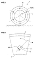
- all of the sensors 10 are arranged equiangularly around the tire rotational axis (i) at the same radial height (j) as shown in Fig.2 .
- the type of the strain sensor 10 various types can be used as far as the sensor 10 can sense the strain and output an electronic data indicative of the magnitude of the strain in this embodiment.
- the sensor should be heat-stable and mechanically stable and durable.
- piezoelectric element, wire resistance strain gauge and the like may be used, but a combination of a magnet 11 and an magnetometric sensor element 12 is preferably used.
- at least one magnet 11 and at least one magnetometric sensor element 12 are embedded in a molded resilient body 13 as one unit 20.
- the resilient body 13 has to deform following the deformation of the tire sidewall 3, therefore, an elastomer material is used.
- thermoplastic elastomer TPE
- various types of elements for example, hall element, MR element, TMF-MI sensor, TMF-FG sensor, amorphous sensor and the like can be used.
- Figs.3 to 5 show examples of such magnet type sensor unit 20.
- the sensor unit 20 includes a single magnetometric sensor element 12 and a single magnet 11.
- the sensor unit 20 includes a plurality of magnetometric sensor elements 12 and a single magnet 11.
- the sensor unit 20 includes a single magnetometric sensor element 12 and a plurality of magnets 11.
- the sensor units 20 each have a directional sensibility, and the maximum sensibility occurs in a direction N.
- the sensor unit 20 in each of the mounting positions, is oriented such that the angle theta between the maximum sensibility direction N and the tire radial direction becomes in a range of 10 to 80 degrees, preferably 20 to 70 degrees in view of the overall accuracy, more preferably 30 to 60 degrees, still more preferably 40 to 50 degrees when viewed from the side of the tire.
- all of the sensors 10 are oriented toward the same direction at the same angle theta.
- the magnitude F of the back-and-forth-direction force and the magnitude E of the surface strain have a linear correlation
- the sensors 10 are fixed to the tire sidewall 3, the sensors 10 are moved around the tire rotational axis as the tire rotates.
- the above-mentioned measuring positions are fixed to a static polar coordinate system having the origin set at the tire rotational axis and being parallel with the tire equatorial plane C.
- the polar angle of zero can be set at any direction, but in this embodiment, for the sake of convenience, it is set at the vertically upward direction as shown in Figs.7 and 8 .
- the number of the measuring positions is preferably an integral multiple of the number of the strain sensors 10 on the basis that the arrangement of the measuring positions and the arrangement of the strain sensors are both equiangular arrangements around the tire rotational axis.
- the angular intervals of the measuring positions are not more than 30 degrees, more preferably not more than 20 degrees, still more preferably not more than 15 degrees, most preferably not more than 10 degrees.
- the number of the measuring positions is preferably not less than 12, more preferably not less than 18, still more preferably not less than 24, most preferably not less than 36.
- the sensor can output data indicative of the magnitude E[n,m] of the strain at the measuring position "m”; the data is fetched and the magnitude E[n,m] is decoded; and using the obtained magnitude E[n,m] and the above-mentioned predefined relational expression, the target force F[n,m] is computed.
- the target force is computed in the same way as above.
- the target force F is once computed based on the output data of one sensor at one measuring position.
- the multiple sensors are provided on the tire sidewall, such computation of the target force F is performed with respect to each of the sensors. More specifically, at a certain point of time during running, when the multiple sensors come to the predetermined fixed measuring positions respectively, the output data of all of the sensors which are indicative of the magnitudes of strain at the respective measuring positions are read and the magnitudes of the strain are obtained. Then, with respect to each of the sensors, in other words, with respect to each of the fixed measuring positions, the target force is computed by the use of a relational expression effectual at the measuring position. Accordingly, on the magnitude of the target force, a plurality of intermediate results are obtained from the multiple sensors.
- a check is performed if each of the intermediate results is within a range of values expected for the measuring position. If out of the expected range, for example very large or vary small, the intermediate result is omitted and not counted in the number of the date. And using the remaining effective intermediate results within the respective expected ranges, the arithmetic mean value is computed.
- Such data validation check can be made at the stage of the magnitude E[n,m] of the strain or the raw data output from the sensor. Namely, with respect to each measuring position "m", a maximum value Emax[m] and a minimum value Emin[m] are determined in advance for example through an experiment. In the checking process, the magnitude E[n,m] is compared with Emax[m] and Emin[m] to determine whether E[n,m] is within the valid range between Emax[m] and Emin[m] or not. If not, the data is not used in the estimation.
- an angle sensor e.g. an encoder, resolver and the like
- the rotational angle (0 to 360 degrees) of the tire is detected to determine the polar angle of a reference point of the tire, and then the positions of the sensors 10 are determined.
- the above-mentioned sensor unit 20 contains a transponder which can transmit the date indicative of the magnitude of the sensed strain towards the electrical control unit in response to a query signal sent via an electromagnetic wave from the electrical control unit on the vehicle body side.
- the transponder comprises a receiver, transmitter, control circuit, data memory and the like which are formed on a semiconductor chip, and an antenna.
- a converter and an electric accumulator/condenser are also incorporated in the unit 20.
- the above-mentioned electrical control unit in this example constitutes a part of ABS (anti lock brake system).
- the present invention is suitably adopted in a brake control system such as ABS of the automobiles, but it is also possible to adopt it in various computer-aided vehicle control systems as far as the back-and-forth-direction force is utilized.
Abstract
Description
- The present invention relates to a method for estimating the magnitude of a back-and-forth-direction force exerted on a pneumatic tire, more particularly to a method capable of estimating the magnitude even if not all of sensors work in order.
- A method for estimating the magnitude of a force exerted on a pneumatic tire is disclosed in
U.S. patent No. 7249498 , wherein it is described that the magnitude of the force in the back-and-forth-direction can be estimated by the use of one or more strain sensors fixed to the tire sidewall. Indeed, it is possible to estimate the magnitude, but it is based on the premise that all of the sensors work in order. - The most important purpose of estimating the magnitude of the back-and-forth-direction force is to control a brake system of the vehicle, for example so as to construct a well-known anti lock brake system (ABS).
- In such a brake system, for safety's sake, it is very important to continue to output the estimated magnitude data toward the brake controller even if not all of the sensors work in order.
- It is therefore, an object of the present invention to provide a method specialized for estimating the magnitude of a back-and-forth-direction force exerted on a pneumatic tire during running, which can continue to output the estimated magnitude date as far as at least one sensor works in order, and which can improve the precision of the estimated magnitude when multiple sensors work in order.
- According to the present invention, a method for estimating the magnitude of a back-and-forth-direction force comprises:
- using multiple strain sensors fixed to a sidewall of the tire at circumferentially different positions around the rotational axis of the tire, wherein each of the strain sensor is capable of outputting data on the magnitude of a strain occurred at the position of the strain sensor;
- reading the output data from the strain sensors when come to measuring positions, wherein the measuring positions are a plurality of fixed positions predetermined around the tire rotational axis;
- in relation to each of the strain sensors positioned at the respective measuring positions,
- calculating the back-and-forth-direction force as an intermediate result by the use of the data read from the strain sensor and a relational expression effectual for the measuring position at which the strain sensor is positioned, whereby a set of the intermediate results are obtained from the respective strain sensors; and
- computing a mean value of only the verified intermediate results/result so as to output it as the estimated magnitude of the back-and-forth-direction force.
- Therefore, unless all of the sensors get out of order, the magnitude of the back-and-forth-direction force can be estimated. Further, by increasing the number of the sensors, the precision of estimation is improved, and the reliability of a system adopting this method such as ABS can be increased, contributing to safe driving.
- A further advantageous aspect is that, although the date processing is completely different from that of
u.s. patent No. 7249498 , there is a possibility that the raw date obtained from the sensors can be used in common with the method ofU.S. patent No. 7249498 . This means that, without the need for additional physical equipments, it is possible to implement both methods with one computer device, and as to the back-and-forth-direction force, the result obtained by the present invention is employed instead of the result obtained byu.s. patent No. 7249498 . - Other and further objects, features and advantages of the invention will appear more fully from the following description.
-
-
Fig.1 is a cross sectional view of a pneumatic tire showing a sensor mounting position. -
Fig.2 is a schematic side view of the pneumatic tire showing an arrangement of six sensors. -
Figs.3, 4 and 5 are schematic views each showing a magnet type strain sensor. -
Fig.6 is a schematic partial side view of the pneumatic tire for explaining the sensor mounting angle. -
Figs.7 and 8 are schematic side views of the tire for explaining the fixed measuring positions and changing sensor positions. - Embodiments of the present invention will now be described in detail in conjunction with the accompanying drawings.
- The present invention can be applied to pneumatic tires of various types with respect to the internal structure, tire size, intended end-usage and the like as far as the tire sidewalls are deformed according to a force in the back-and-forth direction applied between the ground contacting patch of the tire and the tire rotational axis (more precisely the wheel rim on which the tire is mounted).
- As shown in
Fig.1 , apneumatic tire 1 comprises: atread 2, a pair of axially spacedbeads 4 each with abead core 5 therein, a pair ofsidewalls 3 extending between the tread edges and thebeads 4, acarcass 6 extending between thebeads 4, and atread reinforcing belt 7 disposed radially outside thecarcass 6. - The
carcass 6 is composed of at least oneply 6A of cords arranged radially at an angle in the range of from 70 to 90 degrees with respect to the tire equator, extending between thebeads 4 through thetread 2 andsidewalls 3 and turned up around thebead core 5 in eachbead 4 from the axially inside to the axially outside of the tire to form a pair ofturnup portions 6b and amain portion 6a therebetween.
Between themain portion 6a and each turned upportion 6b, abead apex 8 made of a hard rubber is disposed so as to extend radially outwardly from the bead core while tapering towards its radially outer end. - The belt comprises a
breaker 7 and optionally aband 9. Thebreaker 7 comprises: at least twocross plies band 9 is disposed on the radially outside of thebreaker 7 and composed of a cord or cords wound at a small angle of at most about 5 degrees with respect to the tire equator. - According to the present invention, the magnitude F of the above-mentioned force in the back-and-forth direction exerted on the ground contacting patch during running is estimated based on the magnitude of a strain occurred in the
tire sidewall 3 as a result of the tire deformation. - In the case of a pneumatic tire, the magnitude of the surface strain in a specific region Y has a substantially linear correlation with the magnitude F of the force in the back-and-forth direction, therefore, the surface strain is utilized in this embodiment.
- As shown in
Fig.1 , the region Y lies in the middle of thesidewall 3 and extends radially inward and outward from a midpoint M at 50% of the tire section height H by a radial distance L of 25% of the tire section height H. Preferably, the distance L is 20%, more preferably 15% of the tire section height H, wherein the tire section height H is measured from the bead base line BL to the tread surface at the tire equator C. - Within such region Y of one of the
sidewalls 3, a plurality ofstrain sensors 10 are mounted at circumferentially different positions. Preferably, all of thesensors 10 are arranged equiangularly around the tire rotational axis (i) at the same radial height (j) as shown inFig.2 . - As to the type of the
strain sensor 10, various types can be used as far as thesensor 10 can sense the strain and output an electronic data indicative of the magnitude of the strain in this embodiment. In any case, the sensor should be heat-stable and mechanically stable and durable.
For example, piezoelectric element, wire resistance strain gauge and the like may be used, but a combination of amagnet 11 and anmagnetometric sensor element 12 is preferably used.
In such combination, at least onemagnet 11 and at least onemagnetometric sensor element 12 are embedded in a moldedresilient body 13 as oneunit 20.
Theresilient body 13 has to deform following the deformation of thetire sidewall 3, therefore, an elastomer material is used.
In view of easiness of molding such as casting and injection molding, the use of a thermoplastic elastomer (TPE) is especially preferred.
As to themagnetometric sensor element 12, various types of elements, for example, hall element, MR element, TMF-MI sensor, TMF-FG sensor, amorphous sensor and the like can be used. -
Figs.3 to 5 show examples of such magnettype sensor unit 20. InFig.3 , thesensor unit 20 includes a singlemagnetometric sensor element 12 and asingle magnet 11. InFig.4 , thesensor unit 20 includes a plurality ofmagnetometric sensor elements 12 and asingle magnet 11. InFig.5 , thesensor unit 20 includes a singlemagnetometric sensor element 12 and a plurality ofmagnets 11. - The
sensor units 20 each have a directional sensibility, and the maximum sensibility occurs in a direction N. - As shown in
Fig.6 , in each of the mounting positions, thesensor unit 20 is oriented such that the angle theta between the maximum sensibility direction N and the tire radial direction becomes in a range of 10 to 80 degrees, preferably 20 to 70 degrees in view of the overall accuracy, more preferably 30 to 60 degrees, still more preferably 40 to 50 degrees when viewed from the side of the tire. - In order to simplify the subsequent data processing performed by a computer, all of the
sensors 10 are oriented toward the same direction at the same angle theta. - Since the magnitude F of the back-and-forth-direction force and the magnitude E of the surface strain have a linear correlation, the magnitude F can be expressed by an equation of the first degree:

- "n" is an identifying code for the strain sensor,
- "m" is an identifying code for the measuring position, and
- a[m] and b[m] are constants peculiar to the measuring position "m".
- since the
sensors 10 are fixed to thetire sidewall 3, thesensors 10 are moved around the tire rotational axis as the tire rotates. In contrast, the above-mentioned measuring positions are fixed to a static polar coordinate system having the origin set at the tire rotational axis and being parallel with the tire equatorial plane C. The polar angle of zero can be set at any direction, but in this embodiment, for the sake of convenience, it is set at the vertically upward direction as shown inFigs.7 and 8 . - The number of the measuring positions is preferably an integral multiple of the number of the
strain sensors 10 on the basis that the arrangement of the measuring positions and the arrangement of the strain sensors are both equiangular arrangements around the tire rotational axis.
For example, it is preferable that the angular intervals of the measuring positions are not more than 30 degrees, more preferably not more than 20 degrees, still more preferably not more than 15 degrees, most preferably not more than 10 degrees. In other words, the number of the measuring positions is preferably not less than 12, more preferably not less than 18, still more preferably not less than 24, most preferably not less than 36. - Given that the number of the
strain sensors 10 is 6, their identifying codes "n" are "10a", "10b", "10c", "10d", "10e" and "10f", and the number of the measuring positions is 36, their identifying codes "m" are P1,P2,P3 --- P36, the above-mentionedequation 1 is for example: - when
sensor 10a is atposition P1 
- when
sensor 10a is atposition P3 
- During running, when a certain sensor "n" comes to a certain fixed measuring position "m", then: the sensor can output data indicative of the magnitude E[n,m] of the strain at the measuring position "m"; the data is fetched and the magnitude E[n,m] is decoded; and using the obtained magnitude E[n,m] and the above-mentioned predefined relational expression, the target force F[n,m] is computed. At the same time, as the remaining sensors come to the respective measuring positions, with respect to each sensor, the target force is computed in the same way as above.
- In other words, the target force F is once computed based on the output data of one sensor at one measuring position. As the multiple sensors are provided on the tire sidewall, such computation of the target force F is performed with respect to each of the sensors. More specifically, at a certain point of time during running, when the multiple sensors come to the predetermined fixed measuring positions respectively, the output data of all of the sensors which are indicative of the magnitudes of strain at the respective measuring positions are read and the magnitudes of the strain are obtained. Then, with respect to each of the sensors, in other words, with respect to each of the fixed measuring positions, the target force is computed by the use of a relational expression effectual at the measuring position. Accordingly, on the magnitude of the target force, a plurality of intermediate results are obtained from the multiple sensors.
- Then, in order to obtain the final result of the magnitude F, the arithmetic mean value of the intermediate results is computed.
- For example, in the above-explained case of
Fig.7 , there are six intermediate results F[10a,0], F[10b,60], F[10c,120], F[10d,180], F[10e,240] and F[10f,300]. Therefore, the mean value (F[10a,0] + F[10b,60] + F[10c,120] + F[10d,180] + F[10e,240] + F[10f,300])/6 is computed as the final result. - However, before computing the arithmetic mean value, a check is performed if each of the intermediate results is within a range of values expected for the measuring position. If out of the expected range, for example very large or vary small, the intermediate result is omitted and not counted in the number of the date. And using the remaining effective intermediate results within the respective expected ranges, the arithmetic mean value is computed.
- For example, in the above-explained case of
Fig.7 , if F[10a,120] is out of the range expected for the measuring position at the polar angle 120 degree, the intermediate result F[10a,120] is omitted and the mean value (F[10a,0] + F[10b,60] + F[10d,180] + F[10e,240] + F[10f,300])/5 is computed as the final result. - such data validation check can be made at the stage of the magnitude E[n,m] of the strain or the raw data output from the sensor. Namely, with respect to each measuring position "m", a maximum value Emax[m] and a minimum value Emin[m] are determined in advance for example through an experiment. In the checking process, the magnitude E[n,m] is compared with Emax[m] and Emin[m] to determine whether E[n,m] is within the valid range between Emax[m] and Emin[m] or not. If not, the data is not used in the estimation. Practically, either way (1) or (2) is possible: (1) the subsequent computing of the force F[n,m] is not executed regarding the invalid data; (2) the computing of the force F[n,m] is executed, but when computing the arithmetic mean value, the force F[n,m] computed from the invalid data is excluded.
- Further, it is also possible to perform the check at the stage of the intermediate result F[n,m]. In this case, it is effectual to make a mutual comparison of the intermediate results F[n,m]. In the mutual comparison, a result F[n,m] extraordinary larger or smaller than the other data is regarded as invalid, and the invalid result is excluded from the computing of the arithmetic mean value.
- In order to locate the
sensors 10 on the rolling tire, by the use of an angle sensor, e.g. an encoder, resolver and the like, the rotational angle (0 to 360 degrees) of the tire is detected to determine the polar angle of a reference point of the tire, and then the positions of thesensors 10 are determined. - In order to transmit the sensor output data from the rolling tire to an electrical control unit mounted on the vehicle body side, a wireless connection is used. It is therefore preferable that the above-mentioned
sensor unit 20 contains a transponder which can transmit the date indicative of the magnitude of the sensed strain towards the electrical control unit in response to a query signal sent via an electromagnetic wave from the electrical control unit on the vehicle body side. The transponder comprises a receiver, transmitter, control circuit, data memory and the like which are formed on a semiconductor chip, and an antenna. In order to utilize the above-mentioned electromagnetic wave as the source of electric energy, a converter and an electric accumulator/condenser are also incorporated in theunit 20.
The above-mentioned electrical control unit in this example constitutes a part of ABS (anti lock brake system). - The present invention is suitably adopted in a brake control system such as ABS of the automobiles, but it is also possible to adopt it in various computer-aided vehicle control systems as far as the back-and-forth-direction force is utilized.
Claims (10)
- A method for estimating the magnitude of a back-and-forth-direction force exerted on a tire comprising:using a plurality of strain sensors fixed to a sidewall of the tire at circumferentially different positions around the rotational axis of the tire, each said strain sensor capable of outputting data on the magnitude of a strain occurred at the position of the strain sensor;reading the output data from the strain sensors when come to measuring positions, said measuring positions are a plurality of fixed positions predetermined around the tire rotational axis;in relation to each of the strain sensors at the respective measuring positions,calculating the back-and-forth-direction force as an intermediate result by the use of the data read from the strain sensor and a relational expression effectual for the measuring position at which the strain sensor is positioned, whereby a set of the intermediate results are obtained from the respective strain sensors; andcomputing a mean value of only the valid intermediate results or result so as to output it as the estimated magnitude of the back-and-forth-direction force.
- The method according to claim 1, which further comprises
checking if said data read from the strain sensor is within a preset expected range to determine the intermediate result is valid. - The method according to claim 2, wherein
the data which is determined as being out of the preset expected range in said checking, is excluded from the calculating of the back-and-forth-direction force. - The method according to claim 2, wherein
the back-and-forth-direction force calculated from the data which is determined as being out of the preset expected range in said checking, is excluded from the computing of the mean value. - The method according to claim 1, wherein
said strain is a surface strain of the tire sidewall. - The method according to claim 1, wherein
said relational expression is a linear equation. - The method according to claim 1, wherein
the strain sensors are arranged equiangularly around the tire rotational axis. - The method according to claim 1, wherein
said predetermined fixed measuring positions are set at equiangular intervals around the tire rotational axis. - The method according to claim 9, wherein
said equiangular intervals are not more than 10 degrees. - The method according to claim 1, wherein
the strain sensors are arranged equiangularly around the tire rotational axis,
the measuring positions are set at equiangular intervals of not more than 10 degrees, and
the number of the measuring positions is an integral multiple of the number of the strain sensors.
Applications Claiming Priority (1)
| Application Number | Priority Date | Filing Date | Title |
|---|---|---|---|
| JP2007142215A JP4928352B2 (en) | 2007-05-29 | 2007-05-29 | Detection method of longitudinal force acting on tire |
Publications (2)
| Publication Number | Publication Date |
|---|---|
| EP1998158A2 true EP1998158A2 (en) | 2008-12-03 |
| EP1998158A3 EP1998158A3 (en) | 2011-01-05 |
Family
ID=39711854
Family Applications (1)
| Application Number | Title | Priority Date | Filing Date |
|---|---|---|---|
| EP08004592A Ceased EP1998158A3 (en) | 2007-05-29 | 2008-03-12 | Method for estimating magnitude of back-and-forth-direction force exerted on tire |
Country Status (4)
| Country | Link |
|---|---|
| US (1) | US7668669B2 (en) |
| EP (1) | EP1998158A3 (en) |
| JP (1) | JP4928352B2 (en) |
| CN (1) | CN101327719B (en) |
Families Citing this family (10)
| Publication number | Priority date | Publication date | Assignee | Title |
|---|---|---|---|---|
| JP4276686B2 (en) * | 2007-08-21 | 2009-06-10 | 住友ゴム工業株式会社 | Detection method of tire acting force |
| EP2141475B1 (en) * | 2008-07-03 | 2013-03-27 | Snap-on Equipment Srl a unico socio | Apparatus for determining the condition of a tire tread of a vehicle wheel |
| JP5580547B2 (en) * | 2009-04-16 | 2014-08-27 | 住友ゴム工業株式会社 | Method for estimating vertical force acting on tire |
| JP5498227B2 (en) * | 2010-03-30 | 2014-05-21 | 本田技研工業株式会社 | Slip detection device and slip detection method |
| US9827724B2 (en) | 2013-09-17 | 2017-11-28 | Bridgestone Americas Tire Operations, Llc | Tire structure for externally mounted device |
| US9815343B1 (en) * | 2014-06-06 | 2017-11-14 | Iowa State University Research Foundation, Inc. | Tire sensing method for enhanced safety and controllability of vehicles |
| WO2016111672A1 (en) | 2015-01-05 | 2016-07-14 | Compagnie Generale Des Etablissements Michelin | Method of using multiple row sensing device for a tire |
| WO2016111671A1 (en) * | 2015-01-05 | 2016-07-14 | Compagnie Generale Des Etablissements Michelin | Multiple row sensing device for a tire |
| WO2016175783A1 (en) | 2015-04-29 | 2016-11-03 | Compagnie Generale Des Etablissements Michelin | Sensing device with proximity detection for tire inspection |
| US20210138852A1 (en) * | 2017-12-01 | 2021-05-13 | The Yokohama Rubber Co., Ltd. | Tire Assembly and Tire Deformation State Determination System |
Citations (2)
| Publication number | Priority date | Publication date | Assignee | Title |
|---|---|---|---|---|
| US6851307B2 (en) * | 2000-05-26 | 2005-02-08 | Michelin Recherche Et Technique S.A. | Method for determining components of forces exerted on a tire |
| US7249498B2 (en) | 2003-10-27 | 2007-07-31 | Sumitomo Rubber Industries, Ltd. | System and method for determining tire force |
Family Cites Families (12)
| Publication number | Priority date | Publication date | Assignee | Title |
|---|---|---|---|---|
| JPH06174576A (en) * | 1992-12-02 | 1994-06-24 | Toyota Motor Corp | Torque detector |
| DE19900082C2 (en) * | 1999-01-04 | 2003-09-25 | Continental Ag | Friction control system and pneumatic vehicle tires with sensor for it |
| US6308758B1 (en) * | 1999-07-06 | 2001-10-30 | Continental Ag | Elastomeric tire having magnetized sidewall and method of manufacturing same |
| DE10160051A1 (en) * | 2000-12-30 | 2002-07-18 | Bosch Gmbh Robert | Accurate monitoring of motor vehicle sub-systems using measurements of force components acting between a wheel contact surface and the driving surface or wheel bearing sensors |
| JP2004177282A (en) * | 2002-11-27 | 2004-06-24 | Bridgestone Corp | Displacement measuring device and tire circumferential force measuring sensor |
| JP4165320B2 (en) * | 2003-07-23 | 2008-10-15 | トヨタ自動車株式会社 | Tire condition detection device |
| US7568384B2 (en) * | 2003-08-19 | 2009-08-04 | Kabushiki Kaisha Bridgestone | Sensor-incorporated tire and tire condition estimating method |
| JP4377651B2 (en) * | 2003-10-27 | 2009-12-02 | 住友ゴム工業株式会社 | Method for detecting force acting on tire and pneumatic tire used therefor |
| JP4349151B2 (en) * | 2004-02-26 | 2009-10-21 | トヨタ自動車株式会社 | Contact state acquisition device |
| JP4520783B2 (en) * | 2004-07-14 | 2010-08-11 | 住友ゴム工業株式会社 | Detection method of longitudinal force acting on tire |
| JP4713863B2 (en) * | 2004-08-27 | 2011-06-29 | 住友電気工業株式会社 | TIRE SENSOR UNIT, TIRE STATE DETECTION DEVICE, AND TIRE |
| US7469578B2 (en) * | 2005-09-27 | 2008-12-30 | The Yokohama Rubber Co., Ltd. | Method and apparatus for evaluating a cornering stability of a wheel |
-
2007
- 2007-05-29 JP JP2007142215A patent/JP4928352B2/en not_active Expired - Fee Related
-
2008
- 2008-03-12 EP EP08004592A patent/EP1998158A3/en not_active Ceased
- 2008-03-18 US US12/076,407 patent/US7668669B2/en not_active Expired - Fee Related
- 2008-05-28 CN CN2008100982654A patent/CN101327719B/en not_active Expired - Fee Related
Patent Citations (2)
| Publication number | Priority date | Publication date | Assignee | Title |
|---|---|---|---|---|
| US6851307B2 (en) * | 2000-05-26 | 2005-02-08 | Michelin Recherche Et Technique S.A. | Method for determining components of forces exerted on a tire |
| US7249498B2 (en) | 2003-10-27 | 2007-07-31 | Sumitomo Rubber Industries, Ltd. | System and method for determining tire force |
Also Published As
| Publication number | Publication date |
|---|---|
| CN101327719B (en) | 2011-12-07 |
| US20080300801A1 (en) | 2008-12-04 |
| EP1998158A3 (en) | 2011-01-05 |
| CN101327719A (en) | 2008-12-24 |
| JP4928352B2 (en) | 2012-05-09 |
| JP2008298470A (en) | 2008-12-11 |
| US7668669B2 (en) | 2010-02-23 |
Similar Documents
| Publication | Publication Date | Title |
|---|---|---|
| US7668669B2 (en) | Method for estimating magnitude of back-and-forth-direction force exerted on tire | |
| EP1978345B1 (en) | Method for estimating magnitude of force acting on rolling tire | |
| US7249498B2 (en) | System and method for determining tire force | |
| US7513144B2 (en) | Pneumatic tire with specifically arranged strain sensors | |
| CN101281096B (en) | Method for estimating tire force acting on rolling tire | |
| US7243534B2 (en) | Tire state quantity detecting apparatus and method | |
| US7230525B2 (en) | Tire air pressure monitoring system | |
| JP5502404B2 (en) | Method and measuring system for detecting wheel load | |
| EP2655104B1 (en) | Method and system for estimating the load acting on a tire | |
| JP4377651B2 (en) | Method for detecting force acting on tire and pneumatic tire used therefor | |
| CN115335676A (en) | Tire information sensing device | |
| US20230081018A1 (en) | Wear state detection device | |
| CN107848350A (en) | wheel rotation position determining device | |
| JP2010215178A (en) | Method for estimating force applied to tire and pneumatic tire used therefor | |
| CN111405992B (en) | Tire assembly and tire deformation state determination system | |
| JP2009126460A (en) | Failure detection method for tire | |
| JP5542037B2 (en) | Method for estimating force acting on tire | |
| JP6027305B2 (en) | Pneumatic tire | |
| JP5580547B2 (en) | Method for estimating vertical force acting on tire | |
| JP5149531B2 (en) | Method for detecting decrease in tire air pressure | |
| KR101331781B1 (en) | Tire Pressure Monitoring System | |
| JP2009208621A (en) | Camber angle estimation method and camber angle monitoring system | |
| US8354922B2 (en) | Vehicle comprising at least one assembled entity and use of a measurement system | |
| KR101617892B1 (en) | Wheel Position Identify Device in Vehicle and Identify method thereof | |
| JP2023085091A (en) | tire |
Legal Events
| Date | Code | Title | Description |
|---|---|---|---|
| PUAI | Public reference made under article 153(3) epc to a published international application that has entered the european phase |
Free format text: ORIGINAL CODE: 0009012 |
|
| AK | Designated contracting states |
Kind code of ref document: A2 Designated state(s): AT BE BG CH CY CZ DE DK EE ES FI FR GB GR HR HU IE IS IT LI LT LU LV MC MT NL NO PL PT RO SE SI SK TR |
|
| AX | Request for extension of the european patent |
Extension state: AL BA MK RS |
|
| PUAL | Search report despatched |
Free format text: ORIGINAL CODE: 0009013 |
|
| AK | Designated contracting states |
Kind code of ref document: A3 Designated state(s): AT BE BG CH CY CZ DE DK EE ES FI FR GB GR HR HU IE IS IT LI LT LU LV MC MT NL NO PL PT RO SE SI SK TR |
|
| AX | Request for extension of the european patent |
Extension state: AL BA MK RS |
|
| 17P | Request for examination filed |
Effective date: 20110607 |
|
| AKX | Designation fees paid |
Designated state(s): DE FR IT |
|
| 17Q | First examination report despatched |
Effective date: 20141222 |
|
| STAA | Information on the status of an ep patent application or granted ep patent |
Free format text: STATUS: THE APPLICATION HAS BEEN REFUSED |
|
| 18R | Application refused |
Effective date: 20191219 |