EP2001167A1 - A root path computation method in shortest path bridge - Google Patents
A root path computation method in shortest path bridge Download PDFInfo
- Publication number
- EP2001167A1 EP2001167A1 EP07801017A EP07801017A EP2001167A1 EP 2001167 A1 EP2001167 A1 EP 2001167A1 EP 07801017 A EP07801017 A EP 07801017A EP 07801017 A EP07801017 A EP 07801017A EP 2001167 A1 EP2001167 A1 EP 2001167A1
- Authority
- EP
- European Patent Office
- Prior art keywords
- bridge
- root
- path
- port
- minimum
- Prior art date
- Legal status (The legal status is an assumption and is not a legal conclusion. Google has not performed a legal analysis and makes no representation as to the accuracy of the status listed.)
- Granted
Links
Images


Classifications
-
- H—ELECTRICITY
- H04—ELECTRIC COMMUNICATION TECHNIQUE
- H04L—TRANSMISSION OF DIGITAL INFORMATION, e.g. TELEGRAPHIC COMMUNICATION
- H04L12/00—Data switching networks
- H04L12/28—Data switching networks characterised by path configuration, e.g. LAN [Local Area Networks] or WAN [Wide Area Networks]
- H04L12/46—Interconnection of networks
- H04L12/4604—LAN interconnection over a backbone network, e.g. Internet, Frame Relay
- H04L12/462—LAN interconnection over a bridge based backbone
-
- H—ELECTRICITY
- H04—ELECTRIC COMMUNICATION TECHNIQUE
- H04L—TRANSMISSION OF DIGITAL INFORMATION, e.g. TELEGRAPHIC COMMUNICATION
- H04L45/00—Routing or path finding of packets in data switching networks
-
- H—ELECTRICITY
- H04—ELECTRIC COMMUNICATION TECHNIQUE
- H04L—TRANSMISSION OF DIGITAL INFORMATION, e.g. TELEGRAPHIC COMMUNICATION
- H04L45/00—Routing or path finding of packets in data switching networks
- H04L45/12—Shortest path evaluation
-
- H—ELECTRICITY
- H04—ELECTRIC COMMUNICATION TECHNIQUE
- H04L—TRANSMISSION OF DIGITAL INFORMATION, e.g. TELEGRAPHIC COMMUNICATION
- H04L45/00—Routing or path finding of packets in data switching networks
- H04L45/12—Shortest path evaluation
- H04L45/123—Evaluation of link metrics
-
- H—ELECTRICITY
- H04—ELECTRIC COMMUNICATION TECHNIQUE
- H04L—TRANSMISSION OF DIGITAL INFORMATION, e.g. TELEGRAPHIC COMMUNICATION
- H04L45/00—Routing or path finding of packets in data switching networks
- H04L45/48—Routing tree calculation
Definitions
- the present invention relates to the field of network communication, and more particularly to a method of root path calculation in a shortest path bridge.
- a spanning tree is still adopted to forward all the data packets.
- each bridge in the whole network acts as a root bridge to generate a tree, and establish their respective forwarding trees.
- a first bridge where a data packet firstly arrives is taken as a root, and then the data is forwarded according to a forwarding tree established by the bridge itself.
- the entrance is taken as the root to forward data. Therefore, according to the method, a plurality of spanning trees may be employed in the same broadcast domain to forward data.
- a bridge In the method adopted by the TRILL project team of the IETF, a bridge has routing calculation and forwarding functions similar to a router. Therefore, the bridge in this method is also called a route bridge (Rbridge).
- Rbridge can form a "Rbridge network topology" based on a link-state protocol and accordingly calculate a shortest path to any other destination Rbridge.
- a unicast packet As for a unicast packet, each Rbridge can forward a unicast packet along the shortest path according to the address of an exit Rbridge corresponding to the data packet (not based on the address of the final destination node, i.e. not based on the MAC address of a destination host).
- a network including Rbridges may calculate a spanning tree according to the network topology, and broadcast packets, multicast packets, and unknown packets are all forwarded according to the spanning tree.
- a spanning tree is established by employing original spanning tree protocols: Rapid Spanning Tree Protocol and Multiple Spanning Tree Protocol (RSTP/MSTP). This solution is the focus of the current study made by the IEEE.
- a spanning tree is established by employing Intermediate system-Intermediate system (IS-IS) or Open Shortest Path First Protocol (OSPF).
- IS-IS Intermediate system-Intermediate system
- OSPF Open Shortest Path First Protocol
- each bridge After a spanning tree is established by the IS-IS, because each bridge knows the topology of the whole network and the spanning tree established by each bridge includes the spanning trees of the whole network, each bridge knows the branch of the spanning tree where any node is located, and knows how to forward data according to the established spanning tree.
- each bridge after a spanning tree is established by the spanning tree protocol, each bridge only can know a root port and a designated port of one spanning tree passing from the bridge, instead of the information about the whole spanning tree. Therefore, if a unicast packet is forwarded by taking an entrance as the root, each bridge does not know the branch of the spanning tree where a destination address accesses, so that the bridge obtains a forwarding path by address learning.
- the spanning tree of each bridge is generated independently.
- different spanning trees adopt different manners to block the equivalent paths when being generated independently, so that the path selections are inconsistent, and as a result, the forward and backward paths from one bridge to another are inconsistent.
- a path a taking A as the tree root
- a path i taking I as the tree root
- the IEEE proposes a symmetric path generation method of a PATH vector.
- the basic principle for the symmetric path generation method of a PATH vector is to ensure that the path a from the edge bridge A to the edge bridge I is consistent with the path i from the edge bridge I to the edge bridge A.
- an N-bit PATH vector should be predetermined when establishing bridges through using MSTP, in which N cannot be less than the number of bridges in the network, and a fixed bit is assigned to each bridge.
- Bridge ID in ⁇ Root ID, Root Path Cost, designated Bridge ID, Port ID ⁇ in a priority vector is replaced by a PATH vector, so the vector has 64 bits.
- an algorithm or static configuration is adopted in advance to ensure the costs of a link in forward and backward directions to be consistent.
- the PATH vector in the process of establishing multiple spanning trees, the PATH vector is created and propagated in the following manner.
- Each bridge is taken as a tree root to initialize an empty PATH vector, and adds the PATH vector into a Bridge Protocol Data Unit (BPDU) message corresponding to the tree root for being propagated.
- BPDU Bridge Protocol Data Unit
- a BPDU message carrying a PATH vector When a BPDU message carrying a PATH vector is propagated to a certain bridge, if the bridge determines that a port for receiving the BPDU message is a root port of the tree corresponding to the BPDU message according to a unique shortest root cost, and fills the position assigned thereto with 1 in the PATH vector contained in the BPDU message, locally stores the PATH vector, and then continues to propagate the BPDU message carrying the PATH vector to a non-root port. Otherwise, if the bridge calculates two shortest equivalent root costs of a corresponding tree, it carries out the following processes.
- Two PATH vectors corresponding to the two equivalent roots are taken, and the path corresponding to one PATH vector is determined to be blocked according to a specified rule. For example, the values of the two PATH vectors are respectively converted into an N-digit integer, and the vector with a larger value has its corresponding path blocked.
- each bridge marks the corresponding position in the vector with 1 after receiving the BPDU rooted at A.
- B receives the BPDU rooted at A from two different paths
- the PATH vector is shown in the first two rows in Table 1
- E receives the BPDU rooted at I from two different paths
- the PATH vector is shown in the last two rows in Table 1.
- the above method can ensure that, during the generation process of different spanning trees, when equivalent paths exist, the protocols of different spanning trees may determine the blocked paths according to the two equivalent PATH vectors corresponding to the tree and the same blocking rule, thereby ensuring the consistency (symmetry) of forward and backward paths between two points when using different spanning trees to forward data.
- the inventor finds out that the above symmetric path generation method of a PATH vector in the prior art has the defects that, because the number of bits in the PAHT vector is directly proportional to the network size, the number of bits in the PATH vector closely relates to the network scalability, so the method is inappropriate for the network scalability.
- the current PATH vector is 64 bits, which obviously cannot satisfy the requirements of scalability.
- the bit of each bridge needs to be allocated manually in advance, which means a heavy workload.
- the bit allocated to a newly-added bridge in the network is made to be the same as that of another bridge by mistake, the two bridges with incorrect configurations can only be found out by searching all bridges one by one, and the whole network cannot be recovered automatically, thereby causing disastrous consequences to the whole network.
- the present invention provides a method for root path calculation in a shortest path bridge, which is applicable for generating corresponding symmetric paths for different root bridges under a multiple spanning tree circumstance of the shortest path bridge.
- a method for root path calculation in a shortest path bridge includes:
- the present invention selects a path to a root bridge according to the maximum or minimum bridge ID in the equivalent paths, so as to generate symmetric paths for different root bridges under the multiple spanning tree circumstance of a shortest path bridge, which does not need to preset a vector bit for the generation of paths, thereby reducing the possibility of incorrect configurations.
- the present invention has the following advantages.
- the method provided by the prevent invention is applied in an Ethernet with an expanded frame length, for example, the frame length is expanded to over 1518 bytes (at present, some manufacturers have already expanded the conventional frame length of Ethernet to 9216 bytes and applied in practice), the limitation of 64 bridges may be easily broken through, thereby solving the problem in the prior art that the BPDU frame format needs to be modified due to the increase of the vector bit for a path vector.
- the vector potential in the prior art needs to be expanded to 128/256 bits (16/32 bytes), and the number of bytes in the BPDU is greatly increased, whereas the present invention compares through the MAC address, without increasing the number of bytes of the BPDU as the supported bridges are increased.
- FIG. 1 is a schematic view of a network structure connected through Ethernet bridges
- FIG. 2 is a schematic view of a network structure connected through Ethernet bridges
- FIG. 3 is a schematic view of a network structure connected through Ethernet bridges
- FIG. 4 is a flow chart of a method provided according to an embodiment of the present invention.
- FIG. 5 is a schematic view of a network structure connected through Ethernet bridges
- FIG. 6 is a schematic view of a network structure connected through Ethernet bridges
- FIG. 7 is a schematic view of a network structure connected through Ethernet bridges.
- FIG. 8 is a schematic view of a network structure connected through Ethernet bridges.
- the present invention provides a method for root path calculation in a shortest path bridge.
- a path to a root bridge is selected according to a maximum or minimum bridge ID in each equivalent path.
- the present invention is described below by reference to the accompanying drawings.
- the method provided by the present invention is adapted to establish a symmetric tree in the shortest path bridge according to protocols such as a spanning tree protocol, an IS-IS protocol, and an OSPF protocol.
- protocols such as a spanning tree protocol, an IS-IS protocol, and an OSPF protocol.
- FIG. 4 the flow chart of the method provided according to an embodiment of the present invention is shown in FIG. 4 , which includes the following steps.
- Block 4-1 Initial maximum/minimum bridge ID information along the path is set in a priority vector.
- the maximum or minimum bridge ID information along the path is firstly added into ⁇ Root ID, Root Path Cost, designated Bridge ID, Port ID ⁇ in a conventional MSTP priority vector.
- the bridge ID information may be a MAC address of the bridge or a unique bridge mark preset in a domain. Take MAC addresses as an example, the bridge ID information is MAX_MAC_on_the_way (briefly referred to as MAX_MAC). Therefore, a new priority vector in the present invention is ⁇ Root ID, Root Path Cost, designated Bridge ID, designated Port ID, MAX_MAC ⁇ .
- the MAC address of each bridge is replaced by one letter, i.e. the bridge ID, and the MAC addresses are listed in an order of magnitude: A ⁇ B ⁇ C... ⁇ L ⁇ M ⁇ N ⁇ O.
- the number in each line segment represents a port path cost, which is automatically calculated through an algorithm (relevant to a bandwidth supported by the port) or obtained through static configuration. As for two ports connected by one line segment, the port path costs must keep consistent.
- the path cost (A-I) from root bridge A to I has three shortest equivalent paths, which are AEHOJCBI, AEHOLDBI and AEGNMDBI. If the comparison is made based on ⁇ Root ID, Root Path Cost, designated Bridge ID, Port ID ⁇ in the conventional MSTP priority vector, i.e. comparing the designated Bridge ID, because D>C, the bridge B takes the B->C port as the root port and blocks the B->D port, and the block point is shown as a dot close to B in FIG. 5 . Therefore, B selects the path AEHOJCB as a propagation path of the root bridge A.
- the path cost (I-A) from root bridge I to A similarly has the above three shortest equivalent paths.
- the comparison is also made based on ⁇ Root ID, Root Path Cost, designated Bridge ID, Port ID ⁇ in the conventional MSTP priority vector, i.e. comparing the designated Bridge ID. Because H>G, E selects to block the E->H port, and the block point is shown as a dot close to E in FIG. 5 . Therefore, the spanning tree path from A to I selects IBDMNGEA, so the path from A to I is inconsistent with that from I to A.
- Block 4-2 The root bridge sets initial MAX_MAC information in the priority vector and sends a BPDU message carrying the priority vector to a directly-connected bridge to the root bridge.
- the root bridge sets all bits of the initial MAX_MAC as 0. If a minimum bridge ID is adopted, all bits of the initial MAX_MAC are set to F.
- the initial MAX_MAC is set into the priority vector, and a BPDU message carrying the priority vector is sent to the directly-connected bridge of the root bridge.
- Designated Bridge ID represents a designated bridge ID.
- Designated Port ID represents a designated Port Number.
- Block 4-3 The directly-connected bridge reconstructs the priority vector, determines and stores the root port information corresponding to the root bridge, and sends the BPDU carrying the reconstructed priority vector from the non-root port to other bridges according to the received BPDU message.
- the directly-connected bridge determines the new MAX_MAC in the following manner.
- the directly-connected bridge compares its own SELF_MAC with the MAX_MAC in the BPDU message. If SELF_MAC> MAX_MAC, the new MAX_MAC is SELF_MAC, and if SELF_MAC ⁇ MAX_MAC, the new MAX_MAC is still the MAX_MAC in the priority vector.
- the directly-connected bridge stores the determined new root path cost, MAX_MAC and Port ID information corresponding to the root bridge A, and respectively sends the BPDU messages carrying the corresponding reconstructed priority vectors from each non-root port.
- E stores the new root path cost, MAX_MAC and Port ID information corresponding to the root bridge A into a local database.
- Different priority vectors are respectively set for different non-root ports.
- the new root path cost, MAX_MAC and Port ID information corresponding to the root bridge A are set in the priority vector, and the BPDU messages carrying the corresponding priority vectors are sent from each non-root port respectively.
- the priority vectors of E for the bridges H and G are respectively ⁇ MAC_A, 5, MAC_E, 2, MAC_E ⁇ and ⁇ MAC_A, 5, MAC_E, 3, MAC_E ⁇ .
- the designated Bridge ID becomes MAC_E. Port IDs are different, because the ports for E to be connected to H and G are respectively 2 and 3. Then, the bridge E respectively sends the BPDU message carrying the priority vector from the ports 2 and 3.
- Block 4-4 Other bridges reconstruct the priority vector, determine and store the root port information corresponding to the root bridge, and send the BPDU message carrying the priority vector via the non-root port according to the received BPDU message.
- Each of the other bridges stores the determined new root path cost, MAX_MAC and root port information corresponding to the root bridge A, sets a new priority vector, and sends the BPDU message carrying the corresponding priority vector from each non-root port respectively.
- each bridge takes itself as a root bridge to send the BPDU message to establish its own spanning tree, i.e. each bridge performs the process of sending the BPDU message, similar to the bridge A.
- Each bridge in the network receives the BPDU message from each of the other bridges, and according to the received BPDU message, determines and stores the new root path cost, MAX_MAC and corresponding root port information of each of the other bridges.
- the root bridge ID, shortest path cost (root path cost), MAX_MAC and designated Bridge ID information determined by a part of the bridges are shown in Table 2.
- each receiving bridge determines the root port corresponding to the root bridge in the following manner.
- the receiving bridge firstly compares the root path costs to the root bridge calculated by each port, i.e. the total path costs to the root bridge in the paths of each port. If the total path costs to the root bridge in each path are not equal, the port corresponding to the path with a minimum total path cost is selected as the root port corresponding to the root bridge. For example, L receives the BPDU from the root bridge A at two ports respectively, and calculates the total path costs that the total path cost from the port corresponding to O is 11 and the total path cost from the port corresponding to D is 13. Therefore, for the root bridge A, L selects the port connected to O as the root port.
- the maximum bridge IDs (MAX_MAC) in the paths of each port i.e. maximum MAC addresses in the paths of each port are compared. If the maximum MAC addresses in each path are different, the port corresponding to the path with the maximum MAC address is selected as the root port corresponding to the root bridge.
- A-E-H-O-L-D there are two equal paths from A to D: A-E-H-O-L-D and A-E-G-N-M-D, which are the paths with the lowest total path costs among all the paths.
- the maximum MAC address in the path A-E-H-O-L-D is O
- the maximum MAC address in the other path A-E-G-N-M-D is N.
- the two paths have equal total path cost.
- the two paths from D to A are in the same situation. Because O>N, as for the bridge D, if A is taken as the root, the block point is located at the M-D port.
- the root port corresponding to the root bridge is selected in the following manner.
- the receiving bridge receives the BPDU message from the root bridge Y at two or more ports, and the root path costs calculated at each port are equal to each other and minimum compared with other paths, but the MAX_MACs carried in the BPDUs are the same bridge X, in which X is uncertain.
- the receiving bridge queries path-selection information of the spanning tree between this bridge and the bridge X as the root bridge, i.e. the root port selection information of the spanning tree corresponding to the root bridge X on this bridge.
- the root port of the root bridge Y on the receiving bridge is determined, and the bridge X is recorded into the MAX_MAC in the database corresponding to the root bridge Y on the bridge.
- the maximum MAC address in the two paths are both O, which is the above bridge X.
- B needs to query the root port selection information of the spanning tree corresponding to the root bridge O on this bridge, and select the root port corresponding to the root bridge A on this bridge according to a query result.
- the network in FIG. 5 is a multi-path bridge, i.e. the entrance bridge paths are established by taking each bridge as a root, B, D, O, M, H.... These bridges take themselves as the root and send BPDU messages with themselves as the root to the directly-connected bridges from themselves. While determining the root ports, the directly-connected bridges forward the BPDUs corresponding to the root ports towards other non-root ports. Meanwhile, the directly-connected bridges also select the root port and designated ports to other bridges, and establish shortest paths to other bridges. The path from B to A actually relies on the path from B to O. The configured BPDU packet taking A as the root firstly passes through O and then reaches B.
- B has established an optimum path from O to B by taking O as the root, that is, B should have selected a certain port as the root port corresponding to the root bridge O.
- B selects the port from D as the root port, and blocks the C-B port.
- B will select the path A-E-H-O-L-D-B. That is, the port from B to D is selected as a port corresponding to the root bridge A.
- the path from B to A is also determined by the above principle, the finally selected path is consistent, and A selects the symmetric path B-D-L-O-H-E-A.
- the path-selection information between the bridge and the bridge X is not determined a timer with a duration of 2-3 hello time durations is set, and meanwhile, the configuration information of the root bridge is continuously sent out via other ports. Then, the path-selection information between the bridge and the bridge X is waited for being determined, i.e. waiting for the BPDU taking the bridge X itself as the root bridge to reach the bridge B. If the above timer times out for many times, it indicates that a certain problem occurs to the two shortest paths between the bridge X and the bridge.
- B receives the BPDU of the root bridge A from C and D respectively.
- the MAX_MACs carried in the BPDU are the bridge O.
- B has not established root port selection information by taking O as the root bridge, so that B continues to send the BPDU out via other ports and sets a timer to wait for the configured BPDU with O as the root to arrive at.
- the root port information obtained through query is dropped, and B continues to wait for other configured BPDUs with O as the roots to reach, and continues to query the configured BPDU.
- B changes the port if preferable information appears later on and sends the preferable information to other ports.
- the paths O-H-C-B and O-G-D-B have the same path cost.
- the directly-connected path cost of the path B-O is larger than the path costs of the paths O-H-C-B and O-G-D-B.
- O has the maximum bridge ID.
- the bridge IDs are arranged in an order of letters: A ⁇ B ⁇ C ⁇ ... ⁇ E ⁇ H ⁇ I ⁇ ... ⁇ O according to the alphabetic sequence. For example, A creates a spanning tree by taking itself as the root and begins to send BPDU to O, and the BPDU is transmitted to B hop-by-hop according to the above manner.
- O is also started according to the above manner and sends the BPDU with O as the root, but it is slightly later than the tree A.
- B Upon receiving two BPDUs about the root bridge A, B learns that there are two shortest paths to A. The priority vectors in the two shortest paths have the same "maximum MAC value" (i.e. the bridge ID value of bridge O). Therefore, the root port cannot be directly determined. Then, B queries the root port information with O as the root.
- B merely receives the BPDU from the root bridge O at the port P3.
- the root port selection information corresponding to the root bridge needs to be modified.
- the bridge further needs to query path-selection information of other root bridges associated with the bridge X and with equivalent paths, and makes corresponding updating.
- the bridge queries path-selection information of other root bridges associated with the bridge X in the database. That's because if the root port selection information of a certain root bridge at this bridge may rely on the just modified bridge X, i.e. X is an MAX_MAC in the path from a certain root bridge to the bridge, and the path is the shortest one, the previous port information may be incorrect and also need to be modified.
- B cannot determine to select which port directly according to the path cost and the MAX_MAC, B needs to query the corresponding port selection information (the path-selection information of B) with O as the root bridge. Due to a certain reason, C drops or delays the configured BPDU with O as the root bridge. At this time, B merely receives the configured BPDU with O as the root from D, so that B definitely selects D-B when selecting corresponding root port taking O as the root bridge.
- B also turns to O as a reference when selecting a corresponding port with A as the root bridge, and prefers the ports connected to D.
- B compares the path cost from the port (C-B) with that from D and finds out that both the path costs are equal to each other.
- the MAX_MACs in the paths O-H-C-B and O-G-D-B are respectively H and G, and it is determined that H>G after comparison.
- B modifies the path-selection information of the port taking O as the root bridge. Meanwhile, B queries the information about the bridge O in the database. If the information of a certain root bridge on B relies on O, i.e. O is the MAX_MAC in the configured BPDU of a certain root bridge, the corresponding previous port information may be incorrect, and also needs to be modified.
- the root port information on B corresponding to the root bridge A relies on the root port information on B corresponding to the root bridge O, so that the root port information on B corresponding to the root bridge A needs to be modified. If the root port information on B corresponding to a plurality of root bridges relies on the root port information on B corresponding to the root bridge O, it also needs to be modified. Similarly, if A has a larger MAC address than O and the port selection information of another root bridge X on B relies on A, and A is further a maximum MAC address in the shortest path from the root bridge X to the bridge B, the path-selection information of the root port on the bridge B corresponding to the root bridge X further needs to be modified. It is a query and modification process in a nests loop. Of course, all the operations are finished on the bridge B, which merely include querying the database and modifying the information in the database. Therefore, problems associated with different trees caused by different generation time have been solved.
- the bridge ID of the bridge A is compared with that of the bridge B, and herein, A is smaller than B, so that two associated port IDs on the bridge A are compared with each other.
- Port_A_1 is corresponding to Port_B_2 and Port_A_2 is corresponding to Port_B_1.
- the bridge B selects Port_B_2 as the root port, and after the same comparison, A selects Port_A_1 as the root port. In this manner, both A and B select the same path.
- the method of selecting the path to the root bridge through comparing the maximum or minimum bridge IDs in the paths provided by the present invention is also suitable for the IS-IS protocol.
- the IS-IS protocol establishes a symmetric spanning tree through the method of the present invention, which is described below in detail.
- each letter represents the MAC address of each bridge, and A ⁇ B ⁇ C... ⁇ L ⁇ M ⁇ N ⁇ O, and the number on the line segment represents a port path cost.
- H establishes the adjacency relationship with O, G, F, and B, and after LSAs have been exchanged, LSA information in Table 3 may be obtained.
- every two interconnected directly-connected bridges exchange the link state information.
- B may obtain LSA information received from the directly-connected bridge as shown in Table 4.
- Every bridge collects the path cost information of any bridge directly-connected thereto and floods the information to its neighbors. Through exchanging and flooding, when the whole topology becomes stable, every bridge in the same domain stores the path costs of any two directly-connected bridges, and every bridge stores the path cost information as shown in Table 5.
- a method of constructing a shortest path tree based on the path cost information stored in every bridge is described as follows.
- the shortest paths from V0 to each node in a non-descending sequence are constructed one by one, in which the first step is to find out a node closest to V0 and a path to the node; the second step is to find out a node secondary closest to V0 and a path to the node, and so forth; finally, all the shortest paths from V0 to all nodes are found out, so as to construct a whole shortest path tree.
- the path of the symmetric tree cannot be determined.
- the bridge has constructed a whole shortest path tree with itself as the root according to the above method, the root port, designated port and non-designated port corresponding to the bridge with another bridge as the root bridge have been determined accordingly.
- B For an example, firstly B gets to know which bridges are directly-connected thereto, i.e. C, D, H and I. According to the above method, B establishes the shortest path tree with itself as the root through the manner shown in Table 6.
- BD BC BH 1 3 1 9 B Null Null Null In an initial state, the shortest path tree merely has the node B, the candidate path is just the path represented by the line segment directly-connected to B.
- BD BH BCG 3 9 3 B, I, C BI BC Null Null P4 p1 BI and BC are shortest among all the candidate paths, so taken into the shortest path tree; and B, I and C are taken into the set A.
- BGH is the shortest one among all candidate paths, so that the BH is removed from the candidate paths.
- F is not in the set A, so that F is then put into the set A.
- the maximum (minimum) MAC address in the path is obtained by comparison, G>D, so that the BGH is selected as the unique path, and the corresponding port in the bridge B is Bp1.
- O is also selected into the set A.
- the node A is also selected into the set A.
- B I, C, D, G, F, H, O, A BI BC BD BCG BDF BGH BGHO BGOA Null Null Null C D G H O P4 P1 P3 P1 p3 p1 P1 P1
- B has established the shortest paths to all the other nodes, and the corresponding total path costs, the maximum MAC addresses on the path and the corresponding ports of the paths on the bridge are shown in Table 6.
- Every bridge calculates optimum paths to the other bridges, determines the corresponding root port selection information by taking other bridges as the root bridge according to the optimum paths on the bridge, informs the corresponding directly-connected bridge about the root port selection information, and makes the directly-connected bridges determine the corresponding designated ports.
- the established shortest paths to the other bridges and the port information corresponding to the paths are shown in Table 7.
- the ports are also the root ports corresponding to root bridges.
- B determines that the corresponding root port of C, G, H, O and A on B is Bp1
- the corresponding root port of D and G on B is Bp3
- the root port of I on B is Bp4
- B informs the other directly-connected bridges (C, D, I) about the corresponding port selection information through these ports, so that the designated port information with the other bridges as the root may be established on the bridge C. Therefore, corresponding to the bridge C, after receiving the corresponding information of C, G, H, O and A from Cp2, C may determine that Cp2 is the designated port corresponding to the root bridges C, G, H, O and A.
- D may determine that Dp2 is the designated port ID corresponding to the root bridges D and F; But Bp2 and Hp3 ports are neither the root ports corresponding to any root bridge, nor the designated ports corresponding to the root bridge, they are not received and do not forward any user data.
- the bridges D, F ... calculate the shortest paths to the other bridges on the bridge. Therefore, every bridge determines the corresponding root ports with the other bridges as the root at the bridge, and that informs the other corresponding directly-connected bridges to determine the designated ports thereof, thereby determining the shortest path tree among all the bridges.
Abstract
Description
- The present invention relates to the field of network communication, and more particularly to a method of root path calculation in a shortest path bridge.
- In a conventional network interconnected through Ethernet bridges, because the same and unique spanning tree is adopted to forward data in the same broadcast domain, it generally cannot ensure that data packets are forwarded along the shortest path, and as a result, the data packets are intensely transmitted merely in some links. For example, as shown in
FIG. 1 , in the network interconnected through Ethernet bridges, A represents a root bridge, B and C are blocked, and so as to C and D. Therefore, even though both B and D have straight links to C, data packets from B and D to C must be forwarded by A firstly and then reach C, so that the bandwidths between B and C, and C and D are wasted. - In order to enable a bridge to forward data packets along a shortest path, currently, the shortest path bridge project team of an International organization for Standardization IEEE (Institute for Electrical and Electronics Engineers) and the TRILL(Transparent Interconnection of Lots of Links) project team of an International organization for Standardization IETF (Internet Engineering Task Force) have respectively organized researches according to two different methods.
- In the method adopted by the shortest path bridge project team of the IEEE, a spanning tree is still adopted to forward all the data packets. However, each bridge in the whole network acts as a root bridge to generate a tree, and establish their respective forwarding trees. In order to forward data packets, including broadcast packets, multicast packets, unknown packets or unicast packets, along the shortest path, during the process of forwarding data packets, a first bridge where a data packet firstly arrives is taken as a root, and then the data is forwarded according to a forwarding tree established by the bridge itself. In other words, the entrance is taken as the root to forward data. Therefore, according to the method, a plurality of spanning trees may be employed in the same broadcast domain to forward data.
- In the method adopted by the TRILL project team of the IETF, a bridge has routing calculation and forwarding functions similar to a router. Therefore, the bridge in this method is also called a route bridge (Rbridge). Each Rbridge can form a "Rbridge network topology" based on a link-state protocol and accordingly calculate a shortest path to any other destination Rbridge. As for a unicast packet, each Rbridge can forward a unicast packet along the shortest path according to the address of an exit Rbridge corresponding to the data packet (not based on the address of the final destination node, i.e. not based on the MAC address of a destination host). In addition, a network including Rbridges may calculate a spanning tree according to the network topology, and broadcast packets, multicast packets, and unknown packets are all forwarded according to the spanning tree.
- In order to avoid significantly modifying the hardware through adding Time To Live (TTL) process in the loop, in the method adopted by the TRILL project team of the IETF the spanning tree is merely modified, which merely slightly affects the hardware changes. Therefore, at present, in the research on the shortest path bridge, the IEEE has proposed two solutions around the spanning tree.
- 1. A spanning tree is established by employing original spanning tree protocols: Rapid Spanning Tree Protocol and Multiple Spanning Tree Protocol (RSTP/MSTP). This solution is the focus of the current study made by the IEEE.
- 2. A spanning tree is established by employing Intermediate system-Intermediate system (IS-IS) or Open Shortest Path First Protocol (OSPF).
- In the
solution 2, after a spanning tree is established by the IS-IS, because each bridge knows the topology of the whole network and the spanning tree established by each bridge includes the spanning trees of the whole network, each bridge knows the branch of the spanning tree where any node is located, and knows how to forward data according to the established spanning tree. - In the
solution 1, after a spanning tree is established by the spanning tree protocol, each bridge only can know a root port and a designated port of one spanning tree passing from the bridge, instead of the information about the whole spanning tree. Therefore, if a unicast packet is forwarded by taking an entrance as the root, each bridge does not know the branch of the spanning tree where a destination address accesses, so that the bridge obtains a forwarding path by address learning. - However, the spanning tree of each bridge is generated independently. When two or more equivalent paths exist, different spanning trees adopt different manners to block the equivalent paths when being generated independently, so that the path selections are inconsistent, and as a result, the forward and backward paths from one bridge to another are inconsistent. For example, in the network shown in
FIG. 2 , a path a (taking A as the tree root) from an edge bridge A to an edge bridge I is inconsistent with a path i (taking I as the tree root) from the edge bridge I to the edge bridge A. Therefore, the above forwarding mechanism taking an entrance as a root causes difficulties in address learning due to asymmetric paths, and as a result, a normal forwarding path cannot be obtained by a common source address learning method. - In order to overcome the learning obstacles caused by asymmetric paths in the above shortest path forwarding system taking an entrance as a root, in the prior art, the IEEE proposes a symmetric path generation method of a PATH vector.
- The basic principle for the symmetric path generation method of a PATH vector is to ensure that the path a from the edge bridge A to the edge bridge I is consistent with the path i from the edge bridge I to the edge bridge A. In order to implement the method, an N-bit PATH vector should be predetermined when establishing bridges through using MSTP, in which N cannot be less than the number of bridges in the network, and a fixed bit is assigned to each bridge.
- In order to make the original MSTP protocol of the MSTP be compatible, designated Bridge ID in {Root ID, Root Path Cost, designated Bridge ID, Port ID} in a priority vector is replaced by a PATH vector, so the vector has 64 bits. In addition, an algorithm (or static configuration) is adopted in advance to ensure the costs of a link in forward and backward directions to be consistent.
- In the above symmetric path generation method of a PATH vector, in the process of establishing multiple spanning trees, the PATH vector is created and propagated in the following manner.
- Each bridge is taken as a tree root to initialize an empty PATH vector, and adds the PATH vector into a Bridge Protocol Data Unit (BPDU) message corresponding to the tree root for being propagated.
- When a BPDU message carrying a PATH vector is propagated to a certain bridge, if the bridge determines that a port for receiving the BPDU message is a root port of the tree corresponding to the BPDU message according to a unique shortest root cost, and fills the position assigned thereto with 1 in the PATH vector contained in the BPDU message, locally stores the PATH vector, and then continues to propagate the BPDU message carrying the PATH vector to a non-root port. Otherwise, if the bridge calculates two shortest equivalent root costs of a corresponding tree, it carries out the following processes. Two PATH vectors corresponding to the two equivalent roots (the bit in the PATH vectors corresponding to the bridge is set as 1) are taken, and the path corresponding to one PATH vector is determined to be blocked according to a specified rule. For example, the values of the two PATH vectors are respectively converted into an N-digit integer, and the vector with a larger value has its corresponding path blocked.
- As shown in
FIG. 3 , when the BPDU rooted at A is transmitted to E, the bridge E marks the position in the PATH vector corresponding to E with 1, and transmits the newly-constructed BPDU to H and G from two different ports respectively. When receiving the BPDU rooted at A, H marks the position in the PATH vector corresponding to H with 1. When receiving the BPDU rooted at A, G marks the position in the PATH vector corresponding to G with 1. In this way, each bridge marks the corresponding position in the vector with 1 after receiving the BPDU rooted at A. When B receives the BPDU rooted at A from two different paths, the PATH vector is shown in the first two rows in Table 1, and when E receives the BPDU rooted at I from two different paths, the PATH vector is shown in the last two rows in Table 1. -
Table 1 Path A B C D E F G H I AEHCB 1 1 1 0 0 0 0 1 0 AEGDB 1 1 0 1 0 0 1 0 0 IBCHE 0 1 1 0 1 0 0 1 1 IBDGE 0 1 0 1 1 0 1 0 1 - The above method can ensure that, during the generation process of different spanning trees, when equivalent paths exist, the protocols of different spanning trees may determine the blocked paths according to the two equivalent PATH vectors corresponding to the tree and the same blocking rule, thereby ensuring the consistency (symmetry) of forward and backward paths between two points when using different spanning trees to forward data.
- When implementing the present invention, the inventor finds out that the above symmetric path generation method of a PATH vector in the prior art has the defects that, because the number of bits in the PAHT vector is directly proportional to the network size, the number of bits in the PATH vector closely relates to the network scalability, so the method is inappropriate for the network scalability. For the compatibility of protocols, the current PATH vector is 64 bits, which obviously cannot satisfy the requirements of scalability.
- In this method, the bit of each bridge needs to be allocated manually in advance, which means a heavy workload. In addition, once the bit allocated to a newly-added bridge in the network is made to be the same as that of another bridge by mistake, the two bridges with incorrect configurations can only be found out by searching all bridges one by one, and the whole network cannot be recovered automatically, thereby causing disastrous consequences to the whole network.
- Under a special circumstance, two equivalent paths crossed the same bridge, but merely the ports are different. Such a problem may not be solved by this method. In addition, the method is only suitable for a point to point link, but still has the problem of path asymmetry in a multi-point access link.
- The present invention provides a method for root path calculation in a shortest path bridge, which is applicable for generating corresponding symmetric paths for different root bridges under a multiple spanning tree circumstance of the shortest path bridge.
- The objective of the present invention is achieved by the following technical solutions.
- A method for root path calculation in a shortest path bridge includes:
- When a plurality of equivalent paths with an equal total path cost to a root bridge exist, determining a root path corresponding to the root bridge based on a minimum/maximum value of bridge identifier (ID) in the plurality of equivalent paths.
- As known from the technical solution of the present invention, the present invention selects a path to a root bridge according to the maximum or minimum bridge ID in the equivalent paths, so as to generate symmetric paths for different root bridges under the multiple spanning tree circumstance of a shortest path bridge, which does not need to preset a vector bit for the generation of paths, thereby reducing the possibility of incorrect configurations.
- Compared with the prior art, the present invention has the following advantages.
- 1. Under the multiple spanning tree circumstance of the shortest path bridge, symmetric paths are generated for different root bridges, which do not need reconfiguration of a vector bit for the generation of paths, thereby reducing the possibility of incorrect configurations.
- 2. If the method provided by the prevent invention is applied in an Ethernet with an expanded frame length, for example, the frame length is expanded to over 1518 bytes (at present, some manufacturers have already expanded the conventional frame length of Ethernet to 9216 bytes and applied in practice), the limitation of 64 bridges may be easily broken through, thereby solving the problem in the prior art that the BPDU frame format needs to be modified due to the increase of the vector bit for a path vector.
- In order to support 128/256 bridges, the vector potential in the prior art needs to be expanded to 128/256 bits (16/32 bytes), and the number of bytes in the BPDU is greatly increased, whereas the present invention compares through the MAC address, without increasing the number of bytes of the BPDU as the supported bridges are increased.
- 3. When a certain equivalent link fails or is modified, it does not need to determine each root bridge respectively, and when the closest bridge is modified, the information of root port corresponding to the relevant influenced root bridges is also modified.
-
FIG. 1 is a schematic view of a network structure connected through Ethernet bridges; -
FIG. 2 is a schematic view of a network structure connected through Ethernet bridges; -
FIG. 3 is a schematic view of a network structure connected through Ethernet bridges; -
FIG. 4 is a flow chart of a method provided according to an embodiment of the present invention; -
FIG. 5 is a schematic view of a network structure connected through Ethernet bridges; -
FIG. 6 is a schematic view of a network structure connected through Ethernet bridges; -
FIG. 7 is a schematic view of a network structure connected through Ethernet bridges; and -
FIG. 8 is a schematic view of a network structure connected through Ethernet bridges. - The present invention provides a method for root path calculation in a shortest path bridge. According to the present invention, a path to a root bridge is selected according to a maximum or minimum bridge ID in each equivalent path.
- The present invention is described below by reference to the accompanying drawings. The method provided by the present invention is adapted to establish a symmetric tree in the shortest path bridge according to protocols such as a spanning tree protocol, an IS-IS protocol, and an OSPF protocol. Taking the spanning tree protocol as an example, the flow chart of the method provided according to an embodiment of the present invention is shown in
FIG. 4 , which includes the following steps. - Block 4-1: Initial maximum/minimum bridge ID information along the path is set in a priority vector.
- In the present invention, the maximum or minimum bridge ID information along the path is firstly added into {Root ID, Root Path Cost, designated Bridge ID, Port ID} in a conventional MSTP priority vector. Hereinafter, the method of the present invention is described below by taking the maximum bridge ID in a bridge propagation path as an example. The bridge ID information may be a MAC address of the bridge or a unique bridge mark preset in a domain. Take MAC addresses as an example, the bridge ID information is MAX_MAC_on_the_way (briefly referred to as MAX_MAC). Therefore, a new priority vector in the present invention is {Root ID, Root Path Cost, designated Bridge ID, designated Port ID, MAX_MAC}.
- For example, as shown in
FIG. 5 , in a network interconnected through Ethernet bridges, the MAC address of each bridge is replaced by one letter, i.e. the bridge ID, and the MAC addresses are listed in an order of magnitude: A<B<C...<L<M<N<O. The number in each line segment represents a port path cost, which is automatically calculated through an algorithm (relevant to a bandwidth supported by the port) or obtained through static configuration. As for two ports connected by one line segment, the port path costs must keep consistent. - In the network shown in
FIG. 5 , if spanning trees rooted at A and I are respectively established according to the conventional multiple spanning tree protocol in the prior art, the paths of the spanning trees rooted at A and I are asymmetric. - In the spanning tree rooted at A, the path cost (A-I) from root bridge A to I has three shortest equivalent paths, which are AEHOJCBI, AEHOLDBI and AEGNMDBI. If the comparison is made based on {Root ID, Root Path Cost, designated Bridge ID, Port ID} in the conventional MSTP priority vector, i.e. comparing the designated Bridge ID, because D>C, the bridge B takes the B->C port as the root port and blocks the B->D port, and the block point is shown as a dot close to B in
FIG. 5 . Therefore, B selects the path AEHOJCB as a propagation path of the root bridge A. - In the spanning tree rooted at I, the path cost (I-A) from root bridge I to A similarly has the above three shortest equivalent paths. The comparison is also made based on {Root ID, Root Path Cost, designated Bridge ID, Port ID} in the conventional MSTP priority vector, i.e. comparing the designated Bridge ID. Because H>G, E selects to block the E->H port, and the block point is shown as a dot close to E in
FIG. 5 . Therefore, the spanning tree path from A to I selects IBDMNGEA, so the path from A to I is inconsistent with that from I to A. - In
FIG. 5 , many paths are equal and have a nested loop phenomenon, for example, E-H-O-L-D=E-G-N-M-D=7, B-D-L-O=B-C-J-O=5 and E-H-O-L-D-B=E-G-N-M-D-B=B-C-J-O-H-E=10. Assuming these paths are all shortest ones, in the present invention, there is a need to select a symmetric path from these shortest paths. - Block 4-2: The root bridge sets initial MAX_MAC information in the priority vector and sends a BPDU message carrying the priority vector to a directly-connected bridge to the root bridge.
- In order to establish a spanning tree, the root bridge sets all bits of the initial MAX_MAC as 0. If a minimum bridge ID is adopted, all bits of the initial MAX_MAC are set to F. The initial MAX_MAC is set into the priority vector, and a BPDU message carrying the priority vector is sent to the directly-connected bridge of the root bridge.
- In the network shown in
FIG. 5 , for example, the bridge A is taken as the root bridge, and the priority vector in the BPDU message sent from A to the directly-connected bridge E is {Root ID= MAC_A, Root Path Cost=0, designated Bridge ID=MAC_A , designated Port ID= 1, MAX_MAC=0}. Root Path Cost represents a total path cost. At this time, the path cost is the cost of the path A-A, so Root Path Cost=0. Designated Bridge ID represents a designated bridge ID. Designated Port ID represents a designated Port Number. - Block 4-3: The directly-connected bridge reconstructs the priority vector, determines and stores the root port information corresponding to the root bridge, and sends the BPDU carrying the reconstructed priority vector from the non-root port to other bridges according to the received BPDU message.
- After receiving the BPDU message sent from the root bridge, each directly-connected bridge reconstructs a new priority vector, calculates new path cost information in the new priority vector: new root path cost = root path cost + port path cost. Then, a new MAX_MAC is determined, as well as the root port information corresponding to the root bridge.
- The directly-connected bridge determines the new MAX_MAC in the following manner. The directly-connected bridge compares its own SELF_MAC with the MAX_MAC in the BPDU message. If SELF_MAC> MAX_MAC, the new MAX_MAC is SELF_MAC, and if SELF_MAC < MAX_MAC, the new MAX_MAC is still the MAX_MAC in the priority vector.
- How the directly-connected bridge specifically determines the root port information corresponding to the root bridge is described later on.
- The directly-connected bridge stores the determined new root path cost, MAX_MAC and Port ID information corresponding to the root bridge A, and respectively sends the BPDU messages carrying the corresponding reconstructed priority vectors from each non-root port.
- In the above example with the bridge A as the root bridge, after receiving the BPDU message sent from A, E calculates the new root path cost = 5+0 = 5. Because E>A, MAX_MAC=E. The Port ID corresponding to the root bridge A selected by E is 1.
- Then, E stores the new root path cost, MAX_MAC and Port ID information corresponding to the root bridge A into a local database. Different priority vectors are respectively set for different non-root ports. The new root path cost, MAX_MAC and Port ID information corresponding to the root bridge A are set in the priority vector, and the BPDU messages carrying the corresponding priority vectors are sent from each non-root port respectively.
- In the above example with the bridge A as the root bridge, the priority vectors of E for the bridges H and G are respectively {MAC_A, 5, MAC_E, 2, MAC_E} and {MAC_A, 5, MAC_E, 3, MAC_E}. Herein, the designated Bridge ID becomes MAC_E. Port IDs are different, because the ports for E to be connected to H and G are respectively 2 and 3. Then, the bridge E respectively sends the BPDU message carrying the priority vector from the
ports - Block 4-4: Other bridges reconstruct the priority vector, determine and store the root port information corresponding to the root bridge, and send the BPDU message carrying the priority vector via the non-root port according to the received BPDU message.
- After receiving the BPDU message sent from the directly-connected bridge, each of the other bridges reconstructs a new priority vector, calculates a new path cost information of the new priority vector: new root path cost = root path cost + port path cost, and determines a new MAX_MAC according to the manner of determining the MAX_MAC by the root bridge. Meanwhile, the root port information corresponding to the root bridge is determined.
- Each of the other bridges stores the determined new root path cost, MAX_MAC and root port information corresponding to the root bridge A, sets a new priority vector, and sends the BPDU message carrying the corresponding priority vector from each non-root port respectively.
- In the network shown in
FIG. 5 , each bridge takes itself as a root bridge to send the BPDU message to establish its own spanning tree, i.e. each bridge performs the process of sending the BPDU message, similar to the bridge A. Each bridge in the network receives the BPDU message from each of the other bridges, and according to the received BPDU message, determines and stores the new root path cost, MAX_MAC and corresponding root port information of each of the other bridges. - In the network shown in
FIG. 5 , the root bridge ID, shortest path cost (root path cost), MAX_MAC and designated Bridge ID information determined by a part of the bridges are shown in Table 2. -
Table 2 Receiving Bridge E H O C M D B B Root Bridge ID A A A A A A O A Shortest Path Cost 5 8 10 14 11 12 5 15 Maximum Bridge Address in the Path 0 E H O N O L O Designated Bridge ID A E H O N L D D - In the method provided by the present invention, each receiving bridge (including root bridges and other bridges) determines the root port corresponding to the root bridge in the following manner.
- 1. The receiving bridge firstly compares the root path costs to the root bridge calculated by each port, i.e. the total path costs to the root bridge in the paths of each port. If the total path costs to the root bridge in each path are not equal, the port corresponding to the path with a minimum total path cost is selected as the root port corresponding to the root bridge. For example, L receives the BPDU from the root bridge A at two ports respectively, and calculates the total path costs that the total path cost from the port corresponding to O is 11 and the total path cost from the port corresponding to D is 13. Therefore, for the root bridge A, L selects the port connected to O as the root port.
- 2. If the total path costs to the root bridge calculated by the receiving bridge at each port are equal, and the designated Bridge IDs are different, the maximum bridge IDs (MAX_MAC) in the paths of each port, i.e. maximum MAC addresses in the paths of each port are compared. If the maximum MAC addresses in each path are different, the port corresponding to the path with the maximum MAC address is selected as the root port corresponding to the root bridge.
- For example, in the network shown in
FIG. 5 , there are two equal paths from A to D: A-E-H-O-L-D and A-E-G-N-M-D, which are the paths with the lowest total path costs among all the paths. The maximum MAC address in the path A-E-H-O-L-D is O, whereas the maximum MAC address in the other path A-E-G-N-M-D is N. The two paths have equal total path cost. The two paths from D to A are in the same situation. Because O>N, as for the bridge D, if A is taken as the root, the block point is located at the M-D port. On the contrary, if D is taken as the root, E is blocked at G-E, so that A-D and D-A will select the symmetric path A-E-H-O-L-D. Similarly, in the two equivalent paths of B-C-J-O and B-D-L-O, because L>J, B and O will select the symmetric path B-D-L-O through similar way of determination. - 3. If the total path costs to the root bridge calculated by the receiving bridge at each port are equal, the designated Bridge IDs are different, and the MAX_MACs are the same, the root port corresponding to the root bridge is selected in the following manner.
- The receiving bridge receives the BPDU message from the root bridge Y at two or more ports, and the root path costs calculated at each port are equal to each other and minimum compared with other paths, but the MAX_MACs carried in the BPDUs are the same bridge X, in which X is uncertain. Under such a circumstance, the receiving bridge queries path-selection information of the spanning tree between this bridge and the bridge X as the root bridge, i.e. the root port selection information of the spanning tree corresponding to the root bridge X on this bridge. According to the above path-selection information, the root port of the root bridge Y on the receiving bridge is determined, and the bridge X is recorded into the MAX_MAC in the database corresponding to the root bridge Y on the bridge.
- For example, in the network shown in
FIG. 5 , there are two equivalent paths from A to B: A-E-H-O-J-C-B and A-E-H-O-L-D-B, the maximum MAC address in the two paths are both O, which is the above bridge X. At this time, B needs to query the root port selection information of the spanning tree corresponding to the root bridge O on this bridge, and select the root port corresponding to the root bridge A on this bridge according to a query result. - The network in
FIG. 5 is a multi-path bridge, i.e. the entrance bridge paths are established by taking each bridge as a root, B, D, O, M, H.... These bridges take themselves as the root and send BPDU messages with themselves as the root to the directly-connected bridges from themselves. While determining the root ports, the directly-connected bridges forward the BPDUs corresponding to the root ports towards other non-root ports. Meanwhile, the directly-connected bridges also select the root port and designated ports to other bridges, and establish shortest paths to other bridges. The path from B to A actually relies on the path from B to O. The configured BPDU packet taking A as the root firstly passes through O and then reaches B. Under a general situation, B has established an optimum path from O to B by taking O as the root, that is, B should have selected a certain port as the root port corresponding to the root bridge O. When the configured BPDU taking the bridge O as the root reaches B, upon comparison (because L>J), B selects the port from D as the root port, and blocks the C-B port. Finally, B will select the path A-E-H-O-L-D-B. That is, the port from B to D is selected as a port corresponding to the root bridge A. Similarly, the path from B to A is also determined by the above principle, the finally selected path is consistent, and A selects the symmetric path B-D-L-O-H-E-A. - If the path-selection information between the bridge and the bridge X is not determined a timer with a duration of 2-3 hello time durations is set, and meanwhile, the configuration information of the root bridge is continuously sent out via other ports. Then, the path-selection information between the bridge and the bridge X is waited for being determined, i.e. waiting for the BPDU taking the bridge X itself as the root bridge to reach the bridge B. If the above timer times out for many times, it indicates that a certain problem occurs to the two shortest paths between the bridge X and the bridge.
- For example, in the network in
FIG. 5 , B receives the BPDU of the root bridge A from C and D respectively. The MAX_MACs carried in the BPDU are the bridge O. However, B has not established root port selection information by taking O as the root bridge, so that B continues to send the BPDU out via other ports and sets a timer to wait for the configured BPDU with O as the root to arrive at. After the configured BPDU with O as the root arrival, if the root port obtained by the BPDU is not any port associated with the equivalent shortest paths, the root port information obtained through query is dropped, and B continues to wait for other configured BPDUs with O as the roots to reach, and continues to query the configured BPDU. Then, B changes the port if preferable information appears later on and sends the preferable information to other ports. - For example, as shown in
FIG. 6 , in the network interconnected through Ethernet bridges, the paths O-H-C-B and O-G-D-B have the same path cost. The directly-connected path cost of the path B-O is larger than the path costs of the paths O-H-C-B and O-G-D-B. O has the maximum bridge ID. The bridge IDs are arranged in an order of letters: A<B<C<...<E<H<I<...<O according to the alphabetic sequence. For example, A creates a spanning tree by taking itself as the root and begins to send BPDU to O, and the BPDU is transmitted to B hop-by-hop according to the above manner. - O is also started according to the above manner and sends the BPDU with O as the root, but it is slightly later than the tree A. Upon receiving two BPDUs about the root bridge A, B learns that there are two shortest paths to A. The priority vectors in the two shortest paths have the same "maximum MAC value" (i.e. the bridge ID value of bridge O). Therefore, the root port cannot be directly determined. Then, B queries the root port information with O as the root.
- Because the example of the spanning tree with O as the root is started later, B merely receives the BPDU from the root bridge O at the port P3. In this way, as the root port cannot be directly determined due to the two shortest equivalent paths about the tree A, B queries the root port of the tree O, and if the obtained root port is not any port associated with the equivalent shortest paths, B drops the queried root port information, and continues to wait other configured BPDUs, and meanwhile, transmits the configured BPDU of the updated root bridge A downwards.
- If the path-selection information between the bridge and a certain root bridge X is not adapted to determine the root port due to some errors such as dropping or delaying of a message, after the correct BPDU of the root bridge (taking the bridge X as the root) transmitted from an upstream bridge arrival, on the bridge, the root port selection information corresponding to the root bridge needs to be modified. Meanwhile, the bridge further needs to query path-selection information of other root bridges associated with the bridge X and with equivalent paths, and makes corresponding updating. Meanwhile, the bridge queries path-selection information of other root bridges associated with the bridge X in the database. That's because if the root port selection information of a certain root bridge at this bridge may rely on the just modified bridge X, i.e. X is an MAX_MAC in the path from a certain root bridge to the bridge, and the path is the shortest one, the previous port information may be incorrect and also need to be modified.
- For example, in the network shown in
FIG. 6 , there are two shortest equivalent paths from B to A, i.e. A-O-H-C-B and A-O-G-D-B. The maximum MAC addresses in the two paths are both O. At this time, B cannot determine to select which port directly according to the path cost and the MAX_MAC, B needs to query the corresponding port selection information (the path-selection information of B) with O as the root bridge. Due to a certain reason, C drops or delays the configured BPDU with O as the root bridge. At this time, B merely receives the configured BPDU with O as the root from D, so that B definitely selects D-B when selecting corresponding root port taking O as the root bridge. Then, B also turns to O as a reference when selecting a corresponding port with A as the root bridge, and prefers the ports connected to D. When the next configured BPDU with O as the root bridge passes through H and C to reach B, B compares the path cost from the port (C-B) with that from D and finds out that both the path costs are equal to each other. Furthermore, the MAX_MACs in the paths O-H-C-B and O-G-D-B are respectively H and G, and it is determined that H>G after comparison. Then, B modifies the path-selection information of the port taking O as the root bridge. Meanwhile, B queries the information about the bridge O in the database. If the information of a certain root bridge on B relies on O, i.e. O is the MAX_MAC in the configured BPDU of a certain root bridge, the corresponding previous port information may be incorrect, and also needs to be modified. - For example, the root port information on B corresponding to the root bridge A relies on the root port information on B corresponding to the root bridge O, so that the root port information on B corresponding to the root bridge A needs to be modified. If the root port information on B corresponding to a plurality of root bridges relies on the root port information on B corresponding to the root bridge O, it also needs to be modified. Similarly, if A has a larger MAC address than O and the port selection information of another root bridge X on B relies on A, and A is further a maximum MAC address in the shortest path from the root bridge X to the bridge B, the path-selection information of the root port on the bridge B corresponding to the root bridge X further needs to be modified. It is a query and modification process in a nests loop. Of course, all the operations are finished on the bridge B, which merely include querying the database and modifying the information in the database. Therefore, problems associated with different trees caused by different generation time have been solved.
- 4. If the total path costs to the root bridge calculated by the receiving bridge at each port are equal to each other and the designated Bridge IDs are also equal to each other, it indicates that each equivalent path crosses over the same bridge. Therefore, the local bridge IDs at two endpoints of the equivalent paths are compared to find out the bridge with a smaller bridge ID. Then, as for the bridge with the smaller bridge ID, two Port IDs associated with each shortest path are compared. The shortest path connecting to the port with the smaller Port ID is taken as the path to the root bridge.
- For example, as shown in
FIG. 7 , in the network interconnected through Ethernet bridges, a1 and a2 represent costs of two links. If a1 = a2, two equivalent paths exist between the bridges A and B, and the two equivalent paths pass over the same two bridges. Hence, the bridge ID of the bridge A is compared with that of the bridge B, and herein, A is smaller than B, so that two associated port IDs on the bridge A are compared with each other. Port_A_1 is corresponding to Port_B_2 and Port_A_2 is corresponding to Port_B_1. After comparing the two Port IDs on A, the bridge B selects Port_B_2 as the root port, and after the same comparison, A selects Port_A_1 as the root port. In this manner, both A and B select the same path. - The method of selecting the path to the root bridge through comparing the maximum or minimum bridge IDs in the paths provided by the present invention is also suitable for the IS-IS protocol. The IS-IS protocol establishes a symmetric spanning tree through the method of the present invention, which is described below in detail.
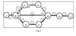
- When the spanning tree is established by IS-IS, the IS-IS is required for establishing adjacency relationship between bridges and exchanging the link state advertisements (LSA). For example, in the network interconnected through Ethernet bridges in
FIG. 8 , each letter represents the MAC address of each bridge, and A<B<C...<L<M<N<O, and the number on the line segment represents a port path cost. - H establishes the adjacency relationship with O, G, F, and B, and after LSAs have been exchanged, LSA information in Table 3 may be obtained.
-
Table 3 Directly-connected bridge ID O G F B H 1 3 2 9 Ports Corresponding to H Hp4 Hp1 Hp3 Hp2 - Likewise, every two interconnected directly-connected bridges exchange the link state information. For example, B may obtain LSA information received from the directly-connected bridge as shown in Table 4.
-
Table 4 Directly-connected bridge ID I C D H B 1 1 3 9 Ports Corresponding to B Bp4 Bp1 Bp3 Bp2 - Every bridge collects the path cost information of any bridge directly-connected thereto and floods the information to its neighbors. Through exchanging and flooding, when the whole topology becomes stable, every bridge in the same domain stores the path costs of any two directly-connected bridges, and every bridge stores the path cost information as shown in Table 5.
-
Table 5 Cost/port A B C D F G H I O A 2 B 1 3 9 1 C 2 D 1 F 2 G 3 H 1 I - Currently, a method of constructing a shortest path tree based on the path cost information stored in every bridge is described as follows. The shortest paths from V0 to each node in a non-descending sequence are constructed one by one, in which the first step is to find out a node closest to V0 and a path to the node; the second step is to find out a node secondary closest to V0 and a path to the node, and so forth; finally, all the shortest paths from V0 to all nodes are found out, so as to construct a whole shortest path tree. However, simply by this method, when there are two or more equivalent paths from V0 to a certain bridge, the path of the symmetric tree cannot be determined.
- If the bridge has constructed a whole shortest path tree with itself as the root according to the above method, the root port, designated port and non-designated port corresponding to the bridge with another bridge as the root bridge have been determined accordingly.
- Taking B for an example, firstly B gets to know which bridges are directly-connected thereto, i.e. C, D, H and I. According to the above method, B establishes the shortest path tree with itself as the root through the manner shown in Table 6.
-
Table 6 Set of Candidate Paths Path Length Set A Shortest Path Maximum MAC in the Shortest Path Port Corresponding to the Shortest Path Descriptions BI
BD
BC
BH 1
3
1
9B Null Null Null In an initial state, the shortest path tree merely has the node B, the candidate path is just the path represented by the line segment directly-connected to B. BD
BH
BCG 3
9
3B,
I,
CBI
BCNull
NullP4
p1BI and BC are shortest among all the candidate paths, so taken into the shortest path tree; and B, I and C are taken into the set A. When all end points of the line segments starting from the nodes I and C just taken into the set A are considered, I does not have such end points, whereas C merely has G As for nodes not collected in the set A, there is merely the node G, so that the value of the path BCG, starting from B, passing through the node C and reaching the node G, is calculated. Because no candidate paths have the path to G, the BCG path is directly put into the set of candidate paths. BDF
BGH4
6B,
I,
C,
D,
GBI
BC
BD
BCGNull
Null
Null
CP4
P1
P3
p1BCG and BD are the shortest among all the candidate paths, so they are put into the set of shortest paths. D and G are taken into the set A. When all end points of the line segments starting from the nodes of the shortest paths are considered, there are respectively H and F. Through calculation, it is found that BGH=6 and BDF=4. There are two paths from B to H, and BGH is the shortest one among all candidate paths, so that the BH is removed from the candidate paths. BGH 6 B,
I,
C,
D,
G,
FBI
BC
BD
BCG
BDFNull
Null
Null
C
DP4
P1
P3
P1
p3Among the above candidate paths, BDF is the shortest one. And F is not in the set A, so that F is then put into the set A. When all end points of the line segments starting from F that are put into the set A are considered, there is H. Through calculation, it is found that BFH=6, so that BFH is put into the candidate paths. So that, two equivalent paths BFH and BGH exist in the candidate paths. BGH
BFH6
6B,
I,
C,
D,
G,
F,
HBI
BC
BD
BCG
BDF
BGHNull
Null
Null
C
D
GP4
P1
P3
P1
p3
p1There are two candidate paths to H with the same path costs. According to the routing algorithm such as OSPF, both of them need to be stored. In order to solve the problem about the MAC address learning, two bridges B and H need to generate the symmetric tree. The maximum (minimum) MAC address in the path is obtained by comparison, G>D, so that the BGH is selected as the unique path, and the corresponding port in the bridge B is Bp1. BHO 7 B,
I,
C,
D,
G,
F,
H,
OBI
BC
BD
BCG
BDF
BGHNull
Null
Null
C
D
GP4
P1
P3
P1
p3
p1When the end points of line segments starting from H that is just put into the set A are considered, there is the unique node O, and BHO=7, which is put into the candidate paths. Because there is only one path, O is also selected into the set A. Similarly, the node A is also selected into the set A. B,
I,
C,
D,
G,
F,
H,
O,
ABI
BC
BD
BCG
BDF
BGH
BGHO
BGOANull
Null
Null
C
D
G
H
OP4
P1
P3
P1
p3
p1
P1
P1Through successive comparison, B has established the shortest paths to all the other nodes, and the corresponding total path costs, the maximum MAC addresses on the path and the corresponding ports of the paths on the bridge are shown in Table 6. - Every bridge calculates optimum paths to the other bridges, determines the corresponding root port selection information by taking other bridges as the root bridge according to the optimum paths on the bridge, informs the corresponding directly-connected bridge about the root port selection information, and makes the directly-connected bridges determine the corresponding designated ports. Taking B for an example, the established shortest paths to the other bridges and the port information corresponding to the paths are shown in Table 7. The ports are also the root ports corresponding to root bridges.
-
Table 7 B A C D F G H I O Path Cost to B and Maximum Bridge ID in the Path 9/ O 1/ null 3/null 4/D 4/C 6/G I/null 7/H Port Corresponding to B Bp1 Bp1 Bp3 Bp3 Bp1 Bp1 Bp4 Bp1 - When B determines that the corresponding root port of C, G, H, O and A on B is Bp1, the corresponding root port of D and G on B is Bp3, and the root port of I on B is Bp4, B informs the other directly-connected bridges (C, D, I) about the corresponding port selection information through these ports, so that the designated port information with the other bridges as the root may be established on the bridge C. Therefore, corresponding to the bridge C, after receiving the corresponding information of C, G, H, O and A from Cp2, C may determine that Cp2 is the designated port corresponding to the root bridges C, G, H, O and A. Similarly, D may determine that Dp2 is the designated port ID corresponding to the root bridges D and F; But Bp2 and Hp3 ports are neither the root ports corresponding to any root bridge, nor the designated ports corresponding to the root bridge, they are not received and do not forward any user data. Similarly, the bridges D, F... calculate the shortest paths to the other bridges on the bridge. Therefore, every bridge determines the corresponding root ports with the other bridges as the root at the bridge, and that informs the other corresponding directly-connected bridges to determine the designated ports thereof, thereby determining the shortest path tree among all the bridges.
- While some embodiments of the invention have been described above, but the protection scope of the present invention is not limited to these. It will be apparent to those skilled in the art that various modifications and variations can be made to the structure of the present invention without departing from the scope or spirit of the invention. Thereby, it is intended that the present invention cover modifications and variations of this invention provided they fall within the scope of the following claims and their equivalents.
Claims (15)
- A method for root path calculation in a shortest path bridge, comprising:when a plurality of equivalent paths with an equal total path cost to a root bridge exist, determining a root path corresponding to the root bridge based on a minimum/maximum value of bridge identifier(ID) in the plurality of equivalent paths.
- The method according to claim 1, further comprising:receiving, by a non-root bridge, a configuration message carrying a priority vector sent by the root bridge, wherein initial maximum or minimum bridge ID information along the path is set in the priority vector; andreconstructing, by the non-root bridge, a priority vector according to the received configuration message, and determining and storing information of a root port and a root path corresponding to the root bridge according to total path cost information and initial maximum or minimum bridge ID information along the path contained in the reconstructed priority vector.
- The method according to claim 2, wherein the process that initial maximum or minimum bridge ID information along the path is set in the priority vector, further comprises:setting, by the root bridge, all bits of an initial maximum bridge ID along the path as zero in the priority vector when the maximum bridge ID is adopted to select a root path corresponding to the root bridge; orsetting, by the root bridge, all bits of an initial minimum bridge ID along the path as F in the priority vector when the minimum bridge ID is adopted to select a root path corresponding to the root bridge.
- The method according to claim 3, wherein the bridge ID comprises a Medium Access Control (MAC) address of a bridge or a unique bridge mark preset in a domain.
- The method according to claim 2, 3, or 4, wherein the process of reconstructing, by the non-root bridge, a priority vector according to the received configuration message, and determining and storing the information of a root port and a root path corresponding to the root bridge according to total path cost information and initial maximum or minimum bridge ID information along the path contained in the reconstructed priority vector further comprises:resetting and storing, by the non-root bridge, a total path cost, a designated bridge ID, a designated bridge port and maximum or minimum bridge ID information along the path in the priority vector in the configuration message after receiving the configuration message from the root bridge at each port; andcomparing, by the non-root bridge, the total path cost information with the initial maximum or minimum bridge ID information along the path in each reconstructed priority vector, determining and storing information of a root port corresponding to the root bridge according to the comparison result, and sending the configuration message carrying the reconstructed priority vector via a non-root port.
- The method according to claim 5, wherein the process of resetting, by the non-root bridge, the maximum or minimum bridge ID information along the path further comprises:setting the bridge ID of the non-root bridge as a maximum bridge ID along the path in the reconstructed priority vector when the maximum bridge ID is adopted to select a root path corresponding to the root bridge and the bridge ID of the non-root bridge is larger than a maximum bridge ID along the path carried in the configuration message; orsetting the bridge ID of the non-root bridge as a minimum bridge ID along the path in the reconstructed priority vector when the minimum bridge ID is adopted to select a root path corresponding to the root bridge and the bridge ID of the non-root bridge is smaller than a minimum bridge ID along the path carried in the configuration message.
- The method according to claim 6, wherein the process of determining and storing, by the non-root bridge, information of a root port corresponding to the root bridge according to a comparison result further comprises:selecting a port where the configuration message, corresponding to the priority vector containing the maximum or minimum bridge ID along the path, passes as a root port corresponding to the root bridge when the priority vectors reset by the non-root bridge comprise a plurality of priority vectors with an equal minimum total path cost, different designated bridge IDs, and different maximum or minimum bridge IDs along the path.
- The method according to claim 6, wherein the process of determining and storing, by the non-root bridge, information of a root port corresponding to the root bridge according to a comparison result further comprises:determining a root port corresponding to the root bridge according to path-selection information of the bridge corresponding to the maximum or minimum bridge ID along the path corresponding to the non-root bridge when each of the priority vectors reset by the non-root bridge contains a plurality of priority vectors with an equal minimum total path cost, different designated bridge IDs and the same maximum or minimum bridge IDs along the path.
- The method according to claim 8, wherein the process of determining a root port corresponding to the root bridge according to path-selection information of the bridge corresponding to the maximum or minimum bridge ID along the path corresponding to the non-root bridge further comprises:continuing to send out the configuration message carrying the reconstructed priority vector and then determining, by the non-root bridge, a root port corresponding to the root bridge according to the subsequently-determined path-selection information. when the path-selection information of the bridge corresponding to the maximum or minimum bridge ID along the path corresponding to the non-root bridge is not determined.
- The method according to claim 8, wherein the process of determining a root port corresponding to the root bridge according to path-selection information of the bridge corresponding to the maximum or minimum bridge ID along the path corresponding to the non-root bridge further comprises:updating the path-selection information according to the subsequently received configuration message and determining a root port corresponding to the root bridge according to the updated path-selection information when the root port of the bridge corresponding to the maximum or minimum bridge ID along the path corresponding to the non-root bridge determined according to the path-selection information is not a port associated with the priority vector containing the minimum total path cost.
- The method according to claim 10, wherein the process of determining a root port corresponding to the root bridge according to the updated path-selection information comprises:updating root port selection information of the non-root bridge corresponding to other bridges and of relying on the path-selection information before updating after updating the path-selection information of the bridge corresponding to the maximum or minimum bridge ID along the path corresponding to the non-root bridge.
- The method according to claim 6, wherein the process of determining and storing, by the non-root bridge, information of a root port corresponding to the root bridge according to a comparison result comprises:selecting a port corresponding to a minimum relevant port number at an endpoint with a smaller bridge ID in two endpoints of the relevant equivalent path of the priority vector as a root port corresponding to the root bridge when each of the priority vector reset, by the non-root bridge, contains a plurality of priority vectors with an equal minimum total path cost, the same designated bridge ID and the same maximum or minimum bridge ID along the path.
- The method according to claim 6, wherein the process of determining and storing, by the non-root bridge, information of a root port corresponding to the root bridge according to a comparison result comprises:selecting a port where a configuration message, corresponding to the priority vector with the minimum total path cost, passes as a root port corresponding to the root bridge when each of the priority vector reset by the non-root bridge contains a priority vector with a minimum total path cost.
- The method according to claim 1, further comprising:establishing an adjacency relationship between each of pairwise interconnected bridges in network, exchanging link state advertisements (LSAs) with each other, each of the pairwise interconnected bridges obtains and stores link state information between all the pairwise interconnected bridges in the whole network; andselecting a path of a bridge corresponding to a maximum or minimum bridge ID along the path as a root path to other root bridges when every bridge in the network calculates a plurality of paths with a minimum total path cost to the other root bridges according to the stored link state information.
- The method according to claim 14, further comprising:sending, by each bridge, information of the root port of the bridge with respect to the other root bridges to an adjacent directly-connected bridge after calculating, by every bridge, the root path to the other root bridges and the root port corresponding to the root path, wherein according to the received information of the root port and according to the received root port information, the directly-connected bridge determines designated port selection information of the other root bridges in the directly-connected bridge.
Applications Claiming Priority (2)
| Application Number | Priority Date | Filing Date | Title |
|---|---|---|---|
| CN200610111994A CN100583825C (en) | 2006-08-30 | 2006-08-30 | Method of generating symmetrical tree in the shortest path bridge |
| PCT/CN2007/070597 WO2008025299A1 (en) | 2006-08-30 | 2007-08-30 | A root path computation method in shortest path bridge |
Publications (3)
| Publication Number | Publication Date |
|---|---|
| EP2001167A1 true EP2001167A1 (en) | 2008-12-10 |
| EP2001167A4 EP2001167A4 (en) | 2009-11-25 |
| EP2001167B1 EP2001167B1 (en) | 2011-01-19 |
Family
ID=39135511
Family Applications (1)
| Application Number | Title | Priority Date | Filing Date |
|---|---|---|---|
| EP07801017A Not-in-force EP2001167B1 (en) | 2006-08-30 | 2007-08-30 | A root path computation method in shortest path bridge |
Country Status (6)
| Country | Link |
|---|---|
| US (1) | US7821963B2 (en) |
| EP (1) | EP2001167B1 (en) |
| CN (1) | CN100583825C (en) |
| AT (1) | ATE496461T1 (en) |
| DE (1) | DE602007012061D1 (en) |
| WO (1) | WO2008025299A1 (en) |
Cited By (70)
| Publication number | Priority date | Publication date | Assignee | Title |
|---|---|---|---|---|
| WO2010111142A1 (en) * | 2009-03-26 | 2010-09-30 | Brocade Communications Systems, Inc . | Redundant host connection in a routed network |
| EP2430799A1 (en) * | 2009-05-13 | 2012-03-21 | Telefonaktiebolaget L M Ericsson (PUBL) | Methods and arrangements for configuring the l2gps in a first stp domain connected towards a second stp domain |
| US8446914B2 (en) | 2010-06-08 | 2013-05-21 | Brocade Communications Systems, Inc. | Method and system for link aggregation across multiple switches |
| US8625616B2 (en) | 2010-05-11 | 2014-01-07 | Brocade Communications Systems, Inc. | Converged network extension |
| US8634308B2 (en) | 2010-06-02 | 2014-01-21 | Brocade Communications Systems, Inc. | Path detection in trill networks |
| US8867552B2 (en) | 2010-05-03 | 2014-10-21 | Brocade Communications Systems, Inc. | Virtual cluster switching |
| US8879549B2 (en) | 2011-06-28 | 2014-11-04 | Brocade Communications Systems, Inc. | Clearing forwarding entries dynamically and ensuring consistency of tables across ethernet fabric switch |
| US8885641B2 (en) | 2011-06-30 | 2014-11-11 | Brocade Communication Systems, Inc. | Efficient trill forwarding |
| US8885488B2 (en) | 2010-06-02 | 2014-11-11 | Brocade Communication Systems, Inc. | Reachability detection in trill networks |
| US8948056B2 (en) | 2011-06-28 | 2015-02-03 | Brocade Communication Systems, Inc. | Spanning-tree based loop detection for an ethernet fabric switch |
| US8989186B2 (en) | 2010-06-08 | 2015-03-24 | Brocade Communication Systems, Inc. | Virtual port grouping for virtual cluster switching |
| US8995444B2 (en) | 2010-03-24 | 2015-03-31 | Brocade Communication Systems, Inc. | Method and system for extending routing domain to non-routing end stations |
| US8995272B2 (en) | 2012-01-26 | 2015-03-31 | Brocade Communication Systems, Inc. | Link aggregation in software-defined networks |
| US9001824B2 (en) | 2010-05-18 | 2015-04-07 | Brocade Communication Systems, Inc. | Fabric formation for virtual cluster switching |
| US9007958B2 (en) | 2011-06-29 | 2015-04-14 | Brocade Communication Systems, Inc. | External loop detection for an ethernet fabric switch |
| US9154416B2 (en) | 2012-03-22 | 2015-10-06 | Brocade Communications Systems, Inc. | Overlay tunnel in a fabric switch |
| US9231890B2 (en) | 2010-06-08 | 2016-01-05 | Brocade Communications Systems, Inc. | Traffic management for virtual cluster switching |
| US9246703B2 (en) | 2010-06-08 | 2016-01-26 | Brocade Communications Systems, Inc. | Remote port mirroring |
| US9270486B2 (en) | 2010-06-07 | 2016-02-23 | Brocade Communications Systems, Inc. | Name services for virtual cluster switching |
| US9270572B2 (en) | 2011-05-02 | 2016-02-23 | Brocade Communications Systems Inc. | Layer-3 support in TRILL networks |
| US9350680B2 (en) | 2013-01-11 | 2016-05-24 | Brocade Communications Systems, Inc. | Protection switching over a virtual link aggregation |
| US9374301B2 (en) | 2012-05-18 | 2016-06-21 | Brocade Communications Systems, Inc. | Network feedback in software-defined networks |
| US9401872B2 (en) | 2012-11-16 | 2016-07-26 | Brocade Communications Systems, Inc. | Virtual link aggregations across multiple fabric switches |
| US9401861B2 (en) | 2011-06-28 | 2016-07-26 | Brocade Communications Systems, Inc. | Scalable MAC address distribution in an Ethernet fabric switch |
| US9401818B2 (en) | 2013-03-15 | 2016-07-26 | Brocade Communications Systems, Inc. | Scalable gateways for a fabric switch |
| US9407533B2 (en) | 2011-06-28 | 2016-08-02 | Brocade Communications Systems, Inc. | Multicast in a trill network |
| US9413691B2 (en) | 2013-01-11 | 2016-08-09 | Brocade Communications Systems, Inc. | MAC address synchronization in a fabric switch |
| US9450870B2 (en) | 2011-11-10 | 2016-09-20 | Brocade Communications Systems, Inc. | System and method for flow management in software-defined networks |
| US9461840B2 (en) | 2010-06-02 | 2016-10-04 | Brocade Communications Systems, Inc. | Port profile management for virtual cluster switching |
| US9521068B2 (en) | 2012-10-16 | 2016-12-13 | Hewlett Packard Enterprise Development Lp | Forwarding packets |
| US9524173B2 (en) | 2014-10-09 | 2016-12-20 | Brocade Communications Systems, Inc. | Fast reboot for a switch |
| US9544219B2 (en) | 2014-07-31 | 2017-01-10 | Brocade Communications Systems, Inc. | Global VLAN services |
| US9548873B2 (en) | 2014-02-10 | 2017-01-17 | Brocade Communications Systems, Inc. | Virtual extensible LAN tunnel keepalives |
| US9548926B2 (en) | 2013-01-11 | 2017-01-17 | Brocade Communications Systems, Inc. | Multicast traffic load balancing over virtual link aggregation |
| US9565113B2 (en) | 2013-01-15 | 2017-02-07 | Brocade Communications Systems, Inc. | Adaptive link aggregation and virtual link aggregation |
| US9565028B2 (en) | 2013-06-10 | 2017-02-07 | Brocade Communications Systems, Inc. | Ingress switch multicast distribution in a fabric switch |
| US9565099B2 (en) | 2013-03-01 | 2017-02-07 | Brocade Communications Systems, Inc. | Spanning tree in fabric switches |
| US9602430B2 (en) | 2012-08-21 | 2017-03-21 | Brocade Communications Systems, Inc. | Global VLANs for fabric switches |
| US9608833B2 (en) | 2010-06-08 | 2017-03-28 | Brocade Communications Systems, Inc. | Supporting multiple multicast trees in trill networks |
| US9628293B2 (en) | 2010-06-08 | 2017-04-18 | Brocade Communications Systems, Inc. | Network layer multicasting in trill networks |
| US9628407B2 (en) | 2014-12-31 | 2017-04-18 | Brocade Communications Systems, Inc. | Multiple software versions in a switch group |
| US9626255B2 (en) | 2014-12-31 | 2017-04-18 | Brocade Communications Systems, Inc. | Online restoration of a switch snapshot |
| US9699001B2 (en) | 2013-06-10 | 2017-07-04 | Brocade Communications Systems, Inc. | Scalable and segregated network virtualization |
| US9699117B2 (en) | 2011-11-08 | 2017-07-04 | Brocade Communications Systems, Inc. | Integrated fibre channel support in an ethernet fabric switch |
| US9699029B2 (en) | 2014-10-10 | 2017-07-04 | Brocade Communications Systems, Inc. | Distributed configuration management in a switch group |
| US9716672B2 (en) | 2010-05-28 | 2017-07-25 | Brocade Communications Systems, Inc. | Distributed configuration management for virtual cluster switching |
| US9736085B2 (en) | 2011-08-29 | 2017-08-15 | Brocade Communications Systems, Inc. | End-to end lossless Ethernet in Ethernet fabric |
| US9742693B2 (en) | 2012-02-27 | 2017-08-22 | Brocade Communications Systems, Inc. | Dynamic service insertion in a fabric switch |
| US9769016B2 (en) | 2010-06-07 | 2017-09-19 | Brocade Communications Systems, Inc. | Advanced link tracking for virtual cluster switching |
| US9800471B2 (en) | 2014-05-13 | 2017-10-24 | Brocade Communications Systems, Inc. | Network extension groups of global VLANs in a fabric switch |
| US9807005B2 (en) | 2015-03-17 | 2017-10-31 | Brocade Communications Systems, Inc. | Multi-fabric manager |
| US9807007B2 (en) | 2014-08-11 | 2017-10-31 | Brocade Communications Systems, Inc. | Progressive MAC address learning |
| US9806906B2 (en) | 2010-06-08 | 2017-10-31 | Brocade Communications Systems, Inc. | Flooding packets on a per-virtual-network basis |
| US9806949B2 (en) | 2013-09-06 | 2017-10-31 | Brocade Communications Systems, Inc. | Transparent interconnection of Ethernet fabric switches |
| US9807031B2 (en) | 2010-07-16 | 2017-10-31 | Brocade Communications Systems, Inc. | System and method for network configuration |
| US9912614B2 (en) | 2015-12-07 | 2018-03-06 | Brocade Communications Systems LLC | Interconnection of switches based on hierarchical overlay tunneling |
| US9912612B2 (en) | 2013-10-28 | 2018-03-06 | Brocade Communications Systems LLC | Extended ethernet fabric switches |
| US9942097B2 (en) | 2015-01-05 | 2018-04-10 | Brocade Communications Systems LLC | Power management in a network of interconnected switches |
| US10003552B2 (en) | 2015-01-05 | 2018-06-19 | Brocade Communications Systems, Llc. | Distributed bidirectional forwarding detection protocol (D-BFD) for cluster of interconnected switches |
| US10038592B2 (en) | 2015-03-17 | 2018-07-31 | Brocade Communications Systems LLC | Identifier assignment to a new switch in a switch group |
| US10063473B2 (en) | 2014-04-30 | 2018-08-28 | Brocade Communications Systems LLC | Method and system for facilitating switch virtualization in a network of interconnected switches |
| US10171303B2 (en) | 2015-09-16 | 2019-01-01 | Avago Technologies International Sales Pte. Limited | IP-based interconnection of switches with a logical chassis |
| US10237090B2 (en) | 2016-10-28 | 2019-03-19 | Avago Technologies International Sales Pte. Limited | Rule-based network identifier mapping |
| US10277464B2 (en) | 2012-05-22 | 2019-04-30 | Arris Enterprises Llc | Client auto-configuration in a multi-switch link aggregation |
| US10439929B2 (en) | 2015-07-31 | 2019-10-08 | Avago Technologies International Sales Pte. Limited | Graceful recovery of a multicast-enabled switch |
| US10454760B2 (en) | 2012-05-23 | 2019-10-22 | Avago Technologies International Sales Pte. Limited | Layer-3 overlay gateways |
| US10476698B2 (en) | 2014-03-20 | 2019-11-12 | Avago Technologies International Sales Pte. Limited | Redundent virtual link aggregation group |
| US10579406B2 (en) | 2015-04-08 | 2020-03-03 | Avago Technologies International Sales Pte. Limited | Dynamic orchestration of overlay tunnels |
| US10581758B2 (en) | 2014-03-19 | 2020-03-03 | Avago Technologies International Sales Pte. Limited | Distributed hot standby links for vLAG |
| US10616108B2 (en) | 2014-07-29 | 2020-04-07 | Avago Technologies International Sales Pte. Limited | Scalable MAC address virtualization |
Families Citing this family (28)
| Publication number | Priority date | Publication date | Assignee | Title |
|---|---|---|---|---|
| US8644186B1 (en) * | 2008-10-03 | 2014-02-04 | Cisco Technology, Inc. | System and method for detecting loops for routing in a network environment |
| US8509248B2 (en) * | 2008-12-29 | 2013-08-13 | Juniper Networks, Inc. | Routing frames in a computer network using bridge identifiers |
| US7787480B1 (en) * | 2009-03-04 | 2010-08-31 | Juniper Networks, Inc. | Routing frames in a trill network using service VLAN identifiers |
| US8345697B2 (en) | 2010-08-17 | 2013-01-01 | Dell Products, Lp | System and method for carrying path information |
| US8711703B2 (en) * | 2010-10-29 | 2014-04-29 | Telefonaktiebolaget L M Ericsson (Publ) | Load balancing in shortest-path-bridging networks |
| US9071629B2 (en) * | 2011-01-07 | 2015-06-30 | Jeda Networks, Inc. | Methods for the interconnection of fibre channel over ethernet devices using shortest path bridging |
| US8811399B2 (en) | 2011-01-07 | 2014-08-19 | Jeda Networks, Inc. | Methods, systems and apparatus for the interconnection of fibre channel over ethernet devices using a fibre channel over ethernet interconnection apparatus controller |
| US9071630B2 (en) * | 2011-01-07 | 2015-06-30 | Jeda Networks, Inc. | Methods for the interconnection of fibre channel over ethernet devices using a trill network |
| US8417806B2 (en) | 2011-05-27 | 2013-04-09 | Dell Products, Lp | System and method for optimizing secured internet small computer system interface storage area networks |
| US9300590B2 (en) | 2011-06-24 | 2016-03-29 | Dell Products, Lp | System and method for dynamic rate control in Ethernet fabrics |
| US9124524B2 (en) * | 2011-06-29 | 2015-09-01 | Broadcom Corporation | System and method for priority based flow control between nodes |
| CN102316033B (en) * | 2011-09-06 | 2017-04-05 | 中兴通讯股份有限公司 | A kind of method and system of specified distribution tree |
| US8693315B2 (en) | 2011-09-13 | 2014-04-08 | Alcatel Lucent | Method and apparatus for shortest path bridging of multicast traffic |
| US9094706B2 (en) | 2011-10-21 | 2015-07-28 | Sonos, Inc. | Systems and methods for wireless music playback |
| US8804572B2 (en) | 2011-10-25 | 2014-08-12 | International Business Machines Corporation | Distributed switch systems in a trill network |
| WO2013105978A1 (en) * | 2012-01-13 | 2013-07-18 | Intel Corporation | Allocation of flow control credits for high performance devices |
| US9025432B2 (en) * | 2012-05-07 | 2015-05-05 | Cisco Technology, Inc. | Optimization for trill LAN hellos |
| CN103428088B (en) * | 2012-05-14 | 2018-11-06 | 中兴通讯股份有限公司 | A kind of distribution of tree root, the method for Message processing and route-bridge |
| CN102694729B (en) * | 2012-05-23 | 2015-08-19 | 神州数码网络(北京)有限公司 | Routing resource in a kind of multilink transparent internet |
| US9160564B2 (en) * | 2012-06-25 | 2015-10-13 | Qualcomm Incorporated | Spanning tree protocol for hybrid networks |
| US9306764B2 (en) * | 2012-06-29 | 2016-04-05 | Sonos, Inc. | Dynamic spanning tree root selection |
| CN102780614B (en) * | 2012-07-12 | 2015-06-17 | 福建星网锐捷网络有限公司 | Spanning tree protocol wiring closet group function enabling method as well as equipment and system |
| US9467365B2 (en) | 2013-02-14 | 2016-10-11 | Cisco Technology, Inc. | Mechanism and framework for finding optimal multicast tree roots without the knowledge of traffic sources and receivers for fabricpath and TRILL |
| US20150036508A1 (en) * | 2013-07-31 | 2015-02-05 | Alcatel Lucent | Method and Apparatus For Gateway Selection In Multilevel SPB Network |
| CN103532847B (en) * | 2013-10-31 | 2017-01-18 | 杭州华三通信技术有限公司 | Method and equipment for optimizing generating tree network topology structure in presence of stacking equipment |
| CN105306294B (en) * | 2015-10-20 | 2018-04-27 | 上海斐讯数据通信技术有限公司 | A kind of Test cases technology system and method for interchanger |
| DE112016006749T5 (en) * | 2016-05-16 | 2019-01-03 | Mitsubishi Electric Corporation | Transmission facility, adaptation facility and parameter adjustment process |
| CN107566268B (en) * | 2016-06-30 | 2021-08-17 | 中兴通讯股份有限公司 | Method and device for acquiring Ethernet path |
Citations (3)
| Publication number | Priority date | Publication date | Assignee | Title |
|---|---|---|---|---|
| US20020196795A1 (en) * | 2001-06-22 | 2002-12-26 | Anritsu Corporation | Communication relay device with redundancy function for line in network in accordance with WAN environment and communication system using the same |
| US6519231B1 (en) * | 1999-01-12 | 2003-02-11 | Nortel Networks Limited | Method and apparatus providing a spanning tree protocol for a data communications network having a multi-link trunk |
| US20050138008A1 (en) * | 2002-12-20 | 2005-06-23 | Tsillas Demetrios J. | Method and apparatus for determining a spanning tree |
Family Cites Families (7)
| Publication number | Priority date | Publication date | Assignee | Title |
|---|---|---|---|---|
| US6202114B1 (en) * | 1997-12-31 | 2001-03-13 | Cisco Technology, Inc. | Spanning tree with fast link-failure convergence |
| US6535490B1 (en) * | 1999-03-04 | 2003-03-18 | 3Com Corporation | High availability spanning tree with rapid reconfiguration with alternate port selection |
| KR100584421B1 (en) * | 2002-07-23 | 2006-05-26 | 삼성전자주식회사 | Bridge management method employing spanning tree algorithm in ethernet passive optical network embodying point-to-point emulation |
| JP3799010B2 (en) * | 2002-12-19 | 2006-07-19 | アンリツ株式会社 | Mesh network bridge |
| US7352707B2 (en) * | 2003-05-28 | 2008-04-01 | D-Link Corporation | Processing method enabling each unit in stacking network device to run rapid spanning tree protocol |
| CN100403731C (en) * | 2004-12-30 | 2008-07-16 | 杭州华三通信技术有限公司 | Method for controlling communication transmission path in stacked equipment domain |
| US20070036161A1 (en) * | 2005-07-13 | 2007-02-15 | Mahamuni Atul B | System and method of routing Ethernet MAC frames using Layer-2 MAC addresses |
-
2006
- 2006-08-30 CN CN200610111994A patent/CN100583825C/en not_active Expired - Fee Related
-
2007
- 2007-08-30 AT AT07801017T patent/ATE496461T1/en not_active IP Right Cessation
- 2007-08-30 WO PCT/CN2007/070597 patent/WO2008025299A1/en active Application Filing
- 2007-08-30 DE DE602007012061T patent/DE602007012061D1/en active Active
- 2007-08-30 EP EP07801017A patent/EP2001167B1/en not_active Not-in-force
-
2009
- 2009-02-27 US US12/394,602 patent/US7821963B2/en active Active
Patent Citations (3)
| Publication number | Priority date | Publication date | Assignee | Title |
|---|---|---|---|---|
| US6519231B1 (en) * | 1999-01-12 | 2003-02-11 | Nortel Networks Limited | Method and apparatus providing a spanning tree protocol for a data communications network having a multi-link trunk |
| US20020196795A1 (en) * | 2001-06-22 | 2002-12-26 | Anritsu Corporation | Communication relay device with redundancy function for line in network in accordance with WAN environment and communication system using the same |
| US20050138008A1 (en) * | 2002-12-20 | 2005-06-23 | Tsillas Demetrios J. | Method and apparatus for determining a spanning tree |
Non-Patent Citations (2)
| Title |
|---|
| NORMAN FINN: "Shortest Path Bridging" IEEE TUTORIAL, [Online] 18 July 2005 (2005-07-18), pages 1-25, XP002533640 Retrieved from the Internet: URL:http://grouper.ieee.org/groups/802/802_tutorials/05-July/nfinn-shortest-path-bridging.pdf> [retrieved on 2009-06-23] * |
| See also references of WO2008025299A1 * |
Cited By (101)
| Publication number | Priority date | Publication date | Assignee | Title |
|---|---|---|---|---|
| US9019976B2 (en) | 2009-03-26 | 2015-04-28 | Brocade Communication Systems, Inc. | Redundant host connection in a routed network |
| US8665886B2 (en) | 2009-03-26 | 2014-03-04 | Brocade Communications Systems, Inc. | Redundant host connection in a routed network |
| WO2010111142A1 (en) * | 2009-03-26 | 2010-09-30 | Brocade Communications Systems, Inc . | Redundant host connection in a routed network |
| EP2430799A1 (en) * | 2009-05-13 | 2012-03-21 | Telefonaktiebolaget L M Ericsson (PUBL) | Methods and arrangements for configuring the l2gps in a first stp domain connected towards a second stp domain |
| EP2430799A4 (en) * | 2009-05-13 | 2014-08-06 | Ericsson Telefon Ab L M | Methods and arrangements for configuring the l2gps in a first stp domain connected towards a second stp domain |
| US8995444B2 (en) | 2010-03-24 | 2015-03-31 | Brocade Communication Systems, Inc. | Method and system for extending routing domain to non-routing end stations |
| US10673703B2 (en) | 2010-05-03 | 2020-06-02 | Avago Technologies International Sales Pte. Limited | Fabric switching |
| US8867552B2 (en) | 2010-05-03 | 2014-10-21 | Brocade Communications Systems, Inc. | Virtual cluster switching |
| US9628336B2 (en) | 2010-05-03 | 2017-04-18 | Brocade Communications Systems, Inc. | Virtual cluster switching |
| US8625616B2 (en) | 2010-05-11 | 2014-01-07 | Brocade Communications Systems, Inc. | Converged network extension |
| US9485148B2 (en) | 2010-05-18 | 2016-11-01 | Brocade Communications Systems, Inc. | Fabric formation for virtual cluster switching |
| US9001824B2 (en) | 2010-05-18 | 2015-04-07 | Brocade Communication Systems, Inc. | Fabric formation for virtual cluster switching |
| US9942173B2 (en) | 2010-05-28 | 2018-04-10 | Brocade Communications System Llc | Distributed configuration management for virtual cluster switching |
| US9716672B2 (en) | 2010-05-28 | 2017-07-25 | Brocade Communications Systems, Inc. | Distributed configuration management for virtual cluster switching |
| US8885488B2 (en) | 2010-06-02 | 2014-11-11 | Brocade Communication Systems, Inc. | Reachability detection in trill networks |
| US8634308B2 (en) | 2010-06-02 | 2014-01-21 | Brocade Communications Systems, Inc. | Path detection in trill networks |
| US9461840B2 (en) | 2010-06-02 | 2016-10-04 | Brocade Communications Systems, Inc. | Port profile management for virtual cluster switching |
| US11757705B2 (en) | 2010-06-07 | 2023-09-12 | Avago Technologies International Sales Pte. Limited | Advanced link tracking for virtual cluster switching |
| US9848040B2 (en) | 2010-06-07 | 2017-12-19 | Brocade Communications Systems, Inc. | Name services for virtual cluster switching |
| US9769016B2 (en) | 2010-06-07 | 2017-09-19 | Brocade Communications Systems, Inc. | Advanced link tracking for virtual cluster switching |
| US10419276B2 (en) | 2010-06-07 | 2019-09-17 | Avago Technologies International Sales Pte. Limited | Advanced link tracking for virtual cluster switching |
| US10924333B2 (en) | 2010-06-07 | 2021-02-16 | Avago Technologies International Sales Pte. Limited | Advanced link tracking for virtual cluster switching |
| US11438219B2 (en) | 2010-06-07 | 2022-09-06 | Avago Technologies International Sales Pte. Limited | Advanced link tracking for virtual cluster switching |
| US9270486B2 (en) | 2010-06-07 | 2016-02-23 | Brocade Communications Systems, Inc. | Name services for virtual cluster switching |
| US8989186B2 (en) | 2010-06-08 | 2015-03-24 | Brocade Communication Systems, Inc. | Virtual port grouping for virtual cluster switching |
| US9246703B2 (en) | 2010-06-08 | 2016-01-26 | Brocade Communications Systems, Inc. | Remote port mirroring |
| US9231890B2 (en) | 2010-06-08 | 2016-01-05 | Brocade Communications Systems, Inc. | Traffic management for virtual cluster switching |
| US8446914B2 (en) | 2010-06-08 | 2013-05-21 | Brocade Communications Systems, Inc. | Method and system for link aggregation across multiple switches |
| US9806906B2 (en) | 2010-06-08 | 2017-10-31 | Brocade Communications Systems, Inc. | Flooding packets on a per-virtual-network basis |
| US9143445B2 (en) | 2010-06-08 | 2015-09-22 | Brocade Communications Systems, Inc. | Method and system for link aggregation across multiple switches |
| US9608833B2 (en) | 2010-06-08 | 2017-03-28 | Brocade Communications Systems, Inc. | Supporting multiple multicast trees in trill networks |
| US9455935B2 (en) | 2010-06-08 | 2016-09-27 | Brocade Communications Systems, Inc. | Remote port mirroring |
| US9461911B2 (en) | 2010-06-08 | 2016-10-04 | Brocade Communications Systems, Inc. | Virtual port grouping for virtual cluster switching |
| US9628293B2 (en) | 2010-06-08 | 2017-04-18 | Brocade Communications Systems, Inc. | Network layer multicasting in trill networks |
| US10348643B2 (en) | 2010-07-16 | 2019-07-09 | Avago Technologies International Sales Pte. Limited | System and method for network configuration |
| US9807031B2 (en) | 2010-07-16 | 2017-10-31 | Brocade Communications Systems, Inc. | System and method for network configuration |
| US9270572B2 (en) | 2011-05-02 | 2016-02-23 | Brocade Communications Systems Inc. | Layer-3 support in TRILL networks |
| US8879549B2 (en) | 2011-06-28 | 2014-11-04 | Brocade Communications Systems, Inc. | Clearing forwarding entries dynamically and ensuring consistency of tables across ethernet fabric switch |
| US8948056B2 (en) | 2011-06-28 | 2015-02-03 | Brocade Communication Systems, Inc. | Spanning-tree based loop detection for an ethernet fabric switch |
| US9350564B2 (en) | 2011-06-28 | 2016-05-24 | Brocade Communications Systems, Inc. | Spanning-tree based loop detection for an ethernet fabric switch |
| US9407533B2 (en) | 2011-06-28 | 2016-08-02 | Brocade Communications Systems, Inc. | Multicast in a trill network |
| US9401861B2 (en) | 2011-06-28 | 2016-07-26 | Brocade Communications Systems, Inc. | Scalable MAC address distribution in an Ethernet fabric switch |
| US9007958B2 (en) | 2011-06-29 | 2015-04-14 | Brocade Communication Systems, Inc. | External loop detection for an ethernet fabric switch |
| US8885641B2 (en) | 2011-06-30 | 2014-11-11 | Brocade Communication Systems, Inc. | Efficient trill forwarding |
| US9112817B2 (en) | 2011-06-30 | 2015-08-18 | Brocade Communications Systems, Inc. | Efficient TRILL forwarding |
| US9736085B2 (en) | 2011-08-29 | 2017-08-15 | Brocade Communications Systems, Inc. | End-to end lossless Ethernet in Ethernet fabric |
| US9699117B2 (en) | 2011-11-08 | 2017-07-04 | Brocade Communications Systems, Inc. | Integrated fibre channel support in an ethernet fabric switch |
| US10164883B2 (en) | 2011-11-10 | 2018-12-25 | Avago Technologies International Sales Pte. Limited | System and method for flow management in software-defined networks |
| US9450870B2 (en) | 2011-11-10 | 2016-09-20 | Brocade Communications Systems, Inc. | System and method for flow management in software-defined networks |
| US8995272B2 (en) | 2012-01-26 | 2015-03-31 | Brocade Communication Systems, Inc. | Link aggregation in software-defined networks |
| US9729387B2 (en) | 2012-01-26 | 2017-08-08 | Brocade Communications Systems, Inc. | Link aggregation in software-defined networks |
| US9742693B2 (en) | 2012-02-27 | 2017-08-22 | Brocade Communications Systems, Inc. | Dynamic service insertion in a fabric switch |
| US9887916B2 (en) | 2012-03-22 | 2018-02-06 | Brocade Communications Systems LLC | Overlay tunnel in a fabric switch |
| US9154416B2 (en) | 2012-03-22 | 2015-10-06 | Brocade Communications Systems, Inc. | Overlay tunnel in a fabric switch |
| US9998365B2 (en) | 2012-05-18 | 2018-06-12 | Brocade Communications Systems, LLC | Network feedback in software-defined networks |
| US9374301B2 (en) | 2012-05-18 | 2016-06-21 | Brocade Communications Systems, Inc. | Network feedback in software-defined networks |
| US10277464B2 (en) | 2012-05-22 | 2019-04-30 | Arris Enterprises Llc | Client auto-configuration in a multi-switch link aggregation |
| US10454760B2 (en) | 2012-05-23 | 2019-10-22 | Avago Technologies International Sales Pte. Limited | Layer-3 overlay gateways |
| US9602430B2 (en) | 2012-08-21 | 2017-03-21 | Brocade Communications Systems, Inc. | Global VLANs for fabric switches |
| US9521068B2 (en) | 2012-10-16 | 2016-12-13 | Hewlett Packard Enterprise Development Lp | Forwarding packets |
| US9401872B2 (en) | 2012-11-16 | 2016-07-26 | Brocade Communications Systems, Inc. | Virtual link aggregations across multiple fabric switches |
| US10075394B2 (en) | 2012-11-16 | 2018-09-11 | Brocade Communications Systems LLC | Virtual link aggregations across multiple fabric switches |
| US9774543B2 (en) | 2013-01-11 | 2017-09-26 | Brocade Communications Systems, Inc. | MAC address synchronization in a fabric switch |
| US9413691B2 (en) | 2013-01-11 | 2016-08-09 | Brocade Communications Systems, Inc. | MAC address synchronization in a fabric switch |
| US9350680B2 (en) | 2013-01-11 | 2016-05-24 | Brocade Communications Systems, Inc. | Protection switching over a virtual link aggregation |
| US9660939B2 (en) | 2013-01-11 | 2017-05-23 | Brocade Communications Systems, Inc. | Protection switching over a virtual link aggregation |
| US9807017B2 (en) | 2013-01-11 | 2017-10-31 | Brocade Communications Systems, Inc. | Multicast traffic load balancing over virtual link aggregation |
| US9548926B2 (en) | 2013-01-11 | 2017-01-17 | Brocade Communications Systems, Inc. | Multicast traffic load balancing over virtual link aggregation |
| US9565113B2 (en) | 2013-01-15 | 2017-02-07 | Brocade Communications Systems, Inc. | Adaptive link aggregation and virtual link aggregation |
| US9565099B2 (en) | 2013-03-01 | 2017-02-07 | Brocade Communications Systems, Inc. | Spanning tree in fabric switches |
| US10462049B2 (en) | 2013-03-01 | 2019-10-29 | Avago Technologies International Sales Pte. Limited | Spanning tree in fabric switches |
| US9871676B2 (en) | 2013-03-15 | 2018-01-16 | Brocade Communications Systems LLC | Scalable gateways for a fabric switch |
| US9401818B2 (en) | 2013-03-15 | 2016-07-26 | Brocade Communications Systems, Inc. | Scalable gateways for a fabric switch |
| US9565028B2 (en) | 2013-06-10 | 2017-02-07 | Brocade Communications Systems, Inc. | Ingress switch multicast distribution in a fabric switch |
| US9699001B2 (en) | 2013-06-10 | 2017-07-04 | Brocade Communications Systems, Inc. | Scalable and segregated network virtualization |
| US9806949B2 (en) | 2013-09-06 | 2017-10-31 | Brocade Communications Systems, Inc. | Transparent interconnection of Ethernet fabric switches |
| US9912612B2 (en) | 2013-10-28 | 2018-03-06 | Brocade Communications Systems LLC | Extended ethernet fabric switches |
| US10355879B2 (en) | 2014-02-10 | 2019-07-16 | Avago Technologies International Sales Pte. Limited | Virtual extensible LAN tunnel keepalives |
| US9548873B2 (en) | 2014-02-10 | 2017-01-17 | Brocade Communications Systems, Inc. | Virtual extensible LAN tunnel keepalives |
| US10581758B2 (en) | 2014-03-19 | 2020-03-03 | Avago Technologies International Sales Pte. Limited | Distributed hot standby links for vLAG |
| US10476698B2 (en) | 2014-03-20 | 2019-11-12 | Avago Technologies International Sales Pte. Limited | Redundent virtual link aggregation group |
| US10063473B2 (en) | 2014-04-30 | 2018-08-28 | Brocade Communications Systems LLC | Method and system for facilitating switch virtualization in a network of interconnected switches |
| US10044568B2 (en) | 2014-05-13 | 2018-08-07 | Brocade Communications Systems LLC | Network extension groups of global VLANs in a fabric switch |
| US9800471B2 (en) | 2014-05-13 | 2017-10-24 | Brocade Communications Systems, Inc. | Network extension groups of global VLANs in a fabric switch |
| US10616108B2 (en) | 2014-07-29 | 2020-04-07 | Avago Technologies International Sales Pte. Limited | Scalable MAC address virtualization |
| US9544219B2 (en) | 2014-07-31 | 2017-01-10 | Brocade Communications Systems, Inc. | Global VLAN services |
| US9807007B2 (en) | 2014-08-11 | 2017-10-31 | Brocade Communications Systems, Inc. | Progressive MAC address learning |
| US10284469B2 (en) | 2014-08-11 | 2019-05-07 | Avago Technologies International Sales Pte. Limited | Progressive MAC address learning |
| US9524173B2 (en) | 2014-10-09 | 2016-12-20 | Brocade Communications Systems, Inc. | Fast reboot for a switch |
| US9699029B2 (en) | 2014-10-10 | 2017-07-04 | Brocade Communications Systems, Inc. | Distributed configuration management in a switch group |
| US9628407B2 (en) | 2014-12-31 | 2017-04-18 | Brocade Communications Systems, Inc. | Multiple software versions in a switch group |
| US9626255B2 (en) | 2014-12-31 | 2017-04-18 | Brocade Communications Systems, Inc. | Online restoration of a switch snapshot |
| US9942097B2 (en) | 2015-01-05 | 2018-04-10 | Brocade Communications Systems LLC | Power management in a network of interconnected switches |
| US10003552B2 (en) | 2015-01-05 | 2018-06-19 | Brocade Communications Systems, Llc. | Distributed bidirectional forwarding detection protocol (D-BFD) for cluster of interconnected switches |
| US10038592B2 (en) | 2015-03-17 | 2018-07-31 | Brocade Communications Systems LLC | Identifier assignment to a new switch in a switch group |
| US9807005B2 (en) | 2015-03-17 | 2017-10-31 | Brocade Communications Systems, Inc. | Multi-fabric manager |
| US10579406B2 (en) | 2015-04-08 | 2020-03-03 | Avago Technologies International Sales Pte. Limited | Dynamic orchestration of overlay tunnels |
| US10439929B2 (en) | 2015-07-31 | 2019-10-08 | Avago Technologies International Sales Pte. Limited | Graceful recovery of a multicast-enabled switch |
| US10171303B2 (en) | 2015-09-16 | 2019-01-01 | Avago Technologies International Sales Pte. Limited | IP-based interconnection of switches with a logical chassis |
| US9912614B2 (en) | 2015-12-07 | 2018-03-06 | Brocade Communications Systems LLC | Interconnection of switches based on hierarchical overlay tunneling |
| US10237090B2 (en) | 2016-10-28 | 2019-03-19 | Avago Technologies International Sales Pte. Limited | Rule-based network identifier mapping |
Also Published As
| Publication number | Publication date |
|---|---|
| DE602007012061D1 (en) | 2011-03-03 |
| EP2001167B1 (en) | 2011-01-19 |
| EP2001167A4 (en) | 2009-11-25 |
| WO2008025299A1 (en) | 2008-03-06 |
| CN101136843A (en) | 2008-03-05 |
| ATE496461T1 (en) | 2011-02-15 |
| US7821963B2 (en) | 2010-10-26 |
| US20090161584A1 (en) | 2009-06-25 |
| CN100583825C (en) | 2010-01-20 |
Similar Documents
| Publication | Publication Date | Title |
|---|---|---|
| EP2001167B1 (en) | A root path computation method in shortest path bridge | |
| CN102150148B (en) | Differentiated services for unicast multicast frames in layer 2 topologies | |
| JP5362743B2 (en) | Tie break for shortest path determination | |
| US7334047B1 (en) | Method and system for selective link state advertisement blocking over a data network area | |
| KR102123035B1 (en) | Three stage folded clos optimization for 802.1aq | |
| EP2614615B1 (en) | Automated traffic engineering for 802.1aq based upon the use of link utilization as feedback into the tie-breaking mechanism | |
| US8559341B2 (en) | System and method for providing a loop free topology in a network environment | |
| US8174967B2 (en) | Method to reduce routing convergence at the edge | |
| US9647928B2 (en) | OSPF point-to-multipoint over broadcast or NBMA mode | |
| CN106063195A (en) | Control device discovery in networks having separate control and forwarding devices | |
| JP5191494B2 (en) | Method for calculating spanning tree based on link state advertisement (LSA), bridge and computer network | |
| WO2007035307A2 (en) | System and method for generating symmetrical spanning trees | |
| US11290394B2 (en) | Traffic control in hybrid networks containing both software defined networking domains and non-SDN IP domains | |
| EP1185041B1 (en) | OSPF autonomous system with a backbone divided into two sub-areas | |
| US8830875B1 (en) | System and method for providing a loop free topology in a network environment | |
| US20160156480A1 (en) | Switching devices | |
| US11855883B2 (en) | System and methods for computing flooding topology | |
| US7701875B2 (en) | OSPF unidirectional link support for unidirectional return paths | |
| Asher | Comprehensive analysis of dynamic routing protocols in computer networks | |
| EL KHADIRI et al. | Comparative Study Between Dynamic IPv6 Routing Protocols of Distance Vectors and Link States | |
| Bonada et al. | RSTP-SP: Shortest path extensions to RSTP | |
| Sharma et al. | Meshed tree protocol for faster convergence in switched networks | |
| KR100810727B1 (en) | A Method of Automatic Protection Switching | |
| Sharma et al. | Performance of Meshed Tree Protocols for Loop Avoidance in Switched Networks | |
| Sharma et al. | RIT Digital Institutional Repositor y |
Legal Events
| Date | Code | Title | Description |
|---|---|---|---|
| PUAI | Public reference made under article 153(3) epc to a published international application that has entered the european phase |
Free format text: ORIGINAL CODE: 0009012 |
|
| 17P | Request for examination filed |
Effective date: 20081022 |
|
| AK | Designated contracting states |
Kind code of ref document: A1 Designated state(s): AT BE BG CH CY CZ DE DK EE ES FI FR GB GR HU IE IS IT LI LT LU LV MC MT NL PL PT RO SE SI SK TR |
|
| RIC1 | Information provided on ipc code assigned before grant |
Ipc: H04L 12/56 20060101AFI20091015BHEP |
|
| A4 | Supplementary search report drawn up and despatched |
Effective date: 20091022 |
|
| 17Q | First examination report despatched |
Effective date: 20091204 |
|
| GRAP | Despatch of communication of intention to grant a patent |
Free format text: ORIGINAL CODE: EPIDOSNIGR1 |
|
| DAX | Request for extension of the european patent (deleted) | ||
| GRAS | Grant fee paid |
Free format text: ORIGINAL CODE: EPIDOSNIGR3 |
|
| GRAA | (expected) grant |
Free format text: ORIGINAL CODE: 0009210 |
|
| AK | Designated contracting states |
Kind code of ref document: B1 Designated state(s): AT BE BG CH CY CZ DE DK EE ES FI FR GB GR HU IE IS IT LI LT LU LV MC MT NL PL PT RO SE SI SK TR |
|
| REG | Reference to a national code |
Ref country code: GB Ref legal event code: FG4D |
|
| REG | Reference to a national code |
Ref country code: CH Ref legal event code: EP |
|
| REG | Reference to a national code |
Ref country code: IE Ref legal event code: FG4D |
|
| REF | Corresponds to: |
Ref document number: 602007012061 Country of ref document: DE Date of ref document: 20110303 Kind code of ref document: P |
|
| REG | Reference to a national code |
Ref country code: DE Ref legal event code: R096 Ref document number: 602007012061 Country of ref document: DE Effective date: 20110303 |
|
| REG | Reference to a national code |
Ref country code: NL Ref legal event code: VDEP Effective date: 20110119 |
|
| LTIE | Lt: invalidation of european patent or patent extension |
Effective date: 20110119 |
|
| PG25 | Lapsed in a contracting state [announced via postgrant information from national office to epo] |
Ref country code: PT Free format text: LAPSE BECAUSE OF FAILURE TO SUBMIT A TRANSLATION OF THE DESCRIPTION OR TO PAY THE FEE WITHIN THE PRESCRIBED TIME-LIMIT Effective date: 20110519 Ref country code: LT Free format text: LAPSE BECAUSE OF FAILURE TO SUBMIT A TRANSLATION OF THE DESCRIPTION OR TO PAY THE FEE WITHIN THE PRESCRIBED TIME-LIMIT Effective date: 20110119 Ref country code: IS Free format text: LAPSE BECAUSE OF FAILURE TO SUBMIT A TRANSLATION OF THE DESCRIPTION OR TO PAY THE FEE WITHIN THE PRESCRIBED TIME-LIMIT Effective date: 20110519 Ref country code: SE Free format text: LAPSE BECAUSE OF FAILURE TO SUBMIT A TRANSLATION OF THE DESCRIPTION OR TO PAY THE FEE WITHIN THE PRESCRIBED TIME-LIMIT Effective date: 20110119 Ref country code: ES Free format text: LAPSE BECAUSE OF FAILURE TO SUBMIT A TRANSLATION OF THE DESCRIPTION OR TO PAY THE FEE WITHIN THE PRESCRIBED TIME-LIMIT Effective date: 20110430 Ref country code: LV Free format text: LAPSE BECAUSE OF FAILURE TO SUBMIT A TRANSLATION OF THE DESCRIPTION OR TO PAY THE FEE WITHIN THE PRESCRIBED TIME-LIMIT Effective date: 20110119 Ref country code: GR Free format text: LAPSE BECAUSE OF FAILURE TO SUBMIT A TRANSLATION OF THE DESCRIPTION OR TO PAY THE FEE WITHIN THE PRESCRIBED TIME-LIMIT Effective date: 20110420 |
|
| PG25 | Lapsed in a contracting state [announced via postgrant information from national office to epo] |
Ref country code: BE Free format text: LAPSE BECAUSE OF FAILURE TO SUBMIT A TRANSLATION OF THE DESCRIPTION OR TO PAY THE FEE WITHIN THE PRESCRIBED TIME-LIMIT Effective date: 20110119 Ref country code: AT Free format text: LAPSE BECAUSE OF FAILURE TO SUBMIT A TRANSLATION OF THE DESCRIPTION OR TO PAY THE FEE WITHIN THE PRESCRIBED TIME-LIMIT Effective date: 20110119 Ref country code: FI Free format text: LAPSE BECAUSE OF FAILURE TO SUBMIT A TRANSLATION OF THE DESCRIPTION OR TO PAY THE FEE WITHIN THE PRESCRIBED TIME-LIMIT Effective date: 20110119 Ref country code: SI Free format text: LAPSE BECAUSE OF FAILURE TO SUBMIT A TRANSLATION OF THE DESCRIPTION OR TO PAY THE FEE WITHIN THE PRESCRIBED TIME-LIMIT Effective date: 20110119 Ref country code: PL Free format text: LAPSE BECAUSE OF FAILURE TO SUBMIT A TRANSLATION OF THE DESCRIPTION OR TO PAY THE FEE WITHIN THE PRESCRIBED TIME-LIMIT Effective date: 20110119 Ref country code: BG Free format text: LAPSE BECAUSE OF FAILURE TO SUBMIT A TRANSLATION OF THE DESCRIPTION OR TO PAY THE FEE WITHIN THE PRESCRIBED TIME-LIMIT Effective date: 20110419 Ref country code: NL Free format text: LAPSE BECAUSE OF FAILURE TO SUBMIT A TRANSLATION OF THE DESCRIPTION OR TO PAY THE FEE WITHIN THE PRESCRIBED TIME-LIMIT Effective date: 20110119 Ref country code: CY Free format text: LAPSE BECAUSE OF FAILURE TO SUBMIT A TRANSLATION OF THE DESCRIPTION OR TO PAY THE FEE WITHIN THE PRESCRIBED TIME-LIMIT Effective date: 20110119 |
|
| PG25 | Lapsed in a contracting state [announced via postgrant information from national office to epo] |
Ref country code: DK Free format text: LAPSE BECAUSE OF FAILURE TO SUBMIT A TRANSLATION OF THE DESCRIPTION OR TO PAY THE FEE WITHIN THE PRESCRIBED TIME-LIMIT Effective date: 20110119 Ref country code: EE Free format text: LAPSE BECAUSE OF FAILURE TO SUBMIT A TRANSLATION OF THE DESCRIPTION OR TO PAY THE FEE WITHIN THE PRESCRIBED TIME-LIMIT Effective date: 20110119 |
|
| PLBE | No opposition filed within time limit |
Free format text: ORIGINAL CODE: 0009261 |
|
| STAA | Information on the status of an ep patent application or granted ep patent |
Free format text: STATUS: NO OPPOSITION FILED WITHIN TIME LIMIT |
|
| PG25 | Lapsed in a contracting state [announced via postgrant information from national office to epo] |
Ref country code: RO Free format text: LAPSE BECAUSE OF FAILURE TO SUBMIT A TRANSLATION OF THE DESCRIPTION OR TO PAY THE FEE WITHIN THE PRESCRIBED TIME-LIMIT Effective date: 20110119 Ref country code: SK Free format text: LAPSE BECAUSE OF FAILURE TO SUBMIT A TRANSLATION OF THE DESCRIPTION OR TO PAY THE FEE WITHIN THE PRESCRIBED TIME-LIMIT Effective date: 20110119 Ref country code: CZ Free format text: LAPSE BECAUSE OF FAILURE TO SUBMIT A TRANSLATION OF THE DESCRIPTION OR TO PAY THE FEE WITHIN THE PRESCRIBED TIME-LIMIT Effective date: 20110119 |
|
| 26N | No opposition filed |
Effective date: 20111020 |
|
| PG25 | Lapsed in a contracting state [announced via postgrant information from national office to epo] |
Ref country code: MT Free format text: LAPSE BECAUSE OF FAILURE TO SUBMIT A TRANSLATION OF THE DESCRIPTION OR TO PAY THE FEE WITHIN THE PRESCRIBED TIME-LIMIT Effective date: 20110119 Ref country code: IT Free format text: LAPSE BECAUSE OF FAILURE TO SUBMIT A TRANSLATION OF THE DESCRIPTION OR TO PAY THE FEE WITHIN THE PRESCRIBED TIME-LIMIT Effective date: 20110119 |
|
| REG | Reference to a national code |
Ref country code: DE Ref legal event code: R097 Ref document number: 602007012061 Country of ref document: DE Effective date: 20111020 |
|
| PG25 | Lapsed in a contracting state [announced via postgrant information from national office to epo] |
Ref country code: MC Free format text: LAPSE BECAUSE OF NON-PAYMENT OF DUE FEES Effective date: 20110831 |
|
| REG | Reference to a national code |
Ref country code: CH Ref legal event code: PL |
|
| PG25 | Lapsed in a contracting state [announced via postgrant information from national office to epo] |
Ref country code: CH Free format text: LAPSE BECAUSE OF NON-PAYMENT OF DUE FEES Effective date: 20110831 Ref country code: LI Free format text: LAPSE BECAUSE OF NON-PAYMENT OF DUE FEES Effective date: 20110831 |
|
| REG | Reference to a national code |
Ref country code: IE Ref legal event code: MM4A |
|
| PG25 | Lapsed in a contracting state [announced via postgrant information from national office to epo] |
Ref country code: IE Free format text: LAPSE BECAUSE OF NON-PAYMENT OF DUE FEES Effective date: 20110830 |
|
| REG | Reference to a national code |
Ref country code: AT Ref legal event code: MK05 Ref document number: 496461 Country of ref document: AT Kind code of ref document: T Effective date: 20110119 |
|
| PG25 | Lapsed in a contracting state [announced via postgrant information from national office to epo] |
Ref country code: LU Free format text: LAPSE BECAUSE OF NON-PAYMENT OF DUE FEES Effective date: 20110830 |
|
| PG25 | Lapsed in a contracting state [announced via postgrant information from national office to epo] |
Ref country code: TR Free format text: LAPSE BECAUSE OF FAILURE TO SUBMIT A TRANSLATION OF THE DESCRIPTION OR TO PAY THE FEE WITHIN THE PRESCRIBED TIME-LIMIT Effective date: 20110119 |
|
| PG25 | Lapsed in a contracting state [announced via postgrant information from national office to epo] |
Ref country code: HU Free format text: LAPSE BECAUSE OF FAILURE TO SUBMIT A TRANSLATION OF THE DESCRIPTION OR TO PAY THE FEE WITHIN THE PRESCRIBED TIME-LIMIT Effective date: 20110119 |
|
| REG | Reference to a national code |
Ref country code: FR Ref legal event code: PLFP Year of fee payment: 10 |
|
| REG | Reference to a national code |
Ref country code: FR Ref legal event code: PLFP Year of fee payment: 11 |
|
| REG | Reference to a national code |
Ref country code: FR Ref legal event code: PLFP Year of fee payment: 12 |
|
| REG | Reference to a national code |
Ref country code: FR Ref legal event code: PLFP Year of fee payment: 15 |
|
| PGFP | Annual fee paid to national office [announced via postgrant information from national office to epo] |
Ref country code: FR Payment date: 20210714 Year of fee payment: 15 |
|
| PGFP | Annual fee paid to national office [announced via postgrant information from national office to epo] |
Ref country code: DE Payment date: 20210720 Year of fee payment: 15 Ref country code: GB Payment date: 20210721 Year of fee payment: 15 |
|
| REG | Reference to a national code |
Ref country code: DE Ref legal event code: R119 Ref document number: 602007012061 Country of ref document: DE |
|
| GBPC | Gb: european patent ceased through non-payment of renewal fee |
Effective date: 20220830 |
|
| PG25 | Lapsed in a contracting state [announced via postgrant information from national office to epo] |
Ref country code: FR Free format text: LAPSE BECAUSE OF NON-PAYMENT OF DUE FEES Effective date: 20220831 Ref country code: DE Free format text: LAPSE BECAUSE OF NON-PAYMENT OF DUE FEES Effective date: 20230301 |
|
| PG25 | Lapsed in a contracting state [announced via postgrant information from national office to epo] |
Ref country code: GB Free format text: LAPSE BECAUSE OF NON-PAYMENT OF DUE FEES Effective date: 20220830 |