EP2008617A2 - Modular progressive implant for a joint articulation surface - Google Patents
Modular progressive implant for a joint articulation surface Download PDFInfo
- Publication number
- EP2008617A2 EP2008617A2 EP08158208A EP08158208A EP2008617A2 EP 2008617 A2 EP2008617 A2 EP 2008617A2 EP 08158208 A EP08158208 A EP 08158208A EP 08158208 A EP08158208 A EP 08158208A EP 2008617 A2 EP2008617 A2 EP 2008617A2
- Authority
- EP
- European Patent Office
- Prior art keywords
- tray
- implant
- keel
- stem
- passageway
- Prior art date
- Legal status (The legal status is an assumption and is not a legal conclusion. Google has not performed a legal analysis and makes no representation as to the accuracy of the status listed.)
- Granted
Links
Images


Classifications
-
- A—HUMAN NECESSITIES
- A61—MEDICAL OR VETERINARY SCIENCE; HYGIENE
- A61F—FILTERS IMPLANTABLE INTO BLOOD VESSELS; PROSTHESES; DEVICES PROVIDING PATENCY TO, OR PREVENTING COLLAPSING OF, TUBULAR STRUCTURES OF THE BODY, e.g. STENTS; ORTHOPAEDIC, NURSING OR CONTRACEPTIVE DEVICES; FOMENTATION; TREATMENT OR PROTECTION OF EYES OR EARS; BANDAGES, DRESSINGS OR ABSORBENT PADS; FIRST-AID KITS
- A61F2/00—Filters implantable into blood vessels; Prostheses, i.e. artificial substitutes or replacements for parts of the body; Appliances for connecting them with the body; Devices providing patency to, or preventing collapsing of, tubular structures of the body, e.g. stents
- A61F2/02—Prostheses implantable into the body
- A61F2/30—Joints
- A61F2/30721—Accessories
- A61F2/30749—Fixation appliances for connecting prostheses to the body
-
- A—HUMAN NECESSITIES
- A61—MEDICAL OR VETERINARY SCIENCE; HYGIENE
- A61F—FILTERS IMPLANTABLE INTO BLOOD VESSELS; PROSTHESES; DEVICES PROVIDING PATENCY TO, OR PREVENTING COLLAPSING OF, TUBULAR STRUCTURES OF THE BODY, e.g. STENTS; ORTHOPAEDIC, NURSING OR CONTRACEPTIVE DEVICES; FOMENTATION; TREATMENT OR PROTECTION OF EYES OR EARS; BANDAGES, DRESSINGS OR ABSORBENT PADS; FIRST-AID KITS
- A61F2/00—Filters implantable into blood vessels; Prostheses, i.e. artificial substitutes or replacements for parts of the body; Appliances for connecting them with the body; Devices providing patency to, or preventing collapsing of, tubular structures of the body, e.g. stents
- A61F2/02—Prostheses implantable into the body
- A61F2/30—Joints
- A61F2/38—Joints for elbows or knees
- A61F2/389—Tibial components
-
- A—HUMAN NECESSITIES
- A61—MEDICAL OR VETERINARY SCIENCE; HYGIENE
- A61B—DIAGNOSIS; SURGERY; IDENTIFICATION
- A61B17/00—Surgical instruments, devices or methods, e.g. tourniquets
- A61B17/56—Surgical instruments or methods for treatment of bones or joints; Devices specially adapted therefor
- A61B17/58—Surgical instruments or methods for treatment of bones or joints; Devices specially adapted therefor for osteosynthesis, e.g. bone plates, screws, setting implements or the like
- A61B17/68—Internal fixation devices, including fasteners and spinal fixators, even if a part thereof projects from the skin
- A61B17/80—Cortical plates, i.e. bone plates; Instruments for holding or positioning cortical plates, or for compressing bones attached to cortical plates
- A61B17/8033—Cortical plates, i.e. bone plates; Instruments for holding or positioning cortical plates, or for compressing bones attached to cortical plates having indirect contact with screw heads, or having contact with screw heads maintained with the aid of additional components, e.g. nuts, wedges or head covers
- A61B17/8047—Cortical plates, i.e. bone plates; Instruments for holding or positioning cortical plates, or for compressing bones attached to cortical plates having indirect contact with screw heads, or having contact with screw heads maintained with the aid of additional components, e.g. nuts, wedges or head covers wherein the additional element surrounds the screw head in the plate hole
-
- A—HUMAN NECESSITIES
- A61—MEDICAL OR VETERINARY SCIENCE; HYGIENE
- A61F—FILTERS IMPLANTABLE INTO BLOOD VESSELS; PROSTHESES; DEVICES PROVIDING PATENCY TO, OR PREVENTING COLLAPSING OF, TUBULAR STRUCTURES OF THE BODY, e.g. STENTS; ORTHOPAEDIC, NURSING OR CONTRACEPTIVE DEVICES; FOMENTATION; TREATMENT OR PROTECTION OF EYES OR EARS; BANDAGES, DRESSINGS OR ABSORBENT PADS; FIRST-AID KITS
- A61F2/00—Filters implantable into blood vessels; Prostheses, i.e. artificial substitutes or replacements for parts of the body; Appliances for connecting them with the body; Devices providing patency to, or preventing collapsing of, tubular structures of the body, e.g. stents
- A61F2/02—Prostheses implantable into the body
- A61F2/30—Joints
- A61F2/32—Joints for the hip
- A61F2/34—Acetabular cups
-
- A—HUMAN NECESSITIES
- A61—MEDICAL OR VETERINARY SCIENCE; HYGIENE
- A61F—FILTERS IMPLANTABLE INTO BLOOD VESSELS; PROSTHESES; DEVICES PROVIDING PATENCY TO, OR PREVENTING COLLAPSING OF, TUBULAR STRUCTURES OF THE BODY, e.g. STENTS; ORTHOPAEDIC, NURSING OR CONTRACEPTIVE DEVICES; FOMENTATION; TREATMENT OR PROTECTION OF EYES OR EARS; BANDAGES, DRESSINGS OR ABSORBENT PADS; FIRST-AID KITS
- A61F2/00—Filters implantable into blood vessels; Prostheses, i.e. artificial substitutes or replacements for parts of the body; Appliances for connecting them with the body; Devices providing patency to, or preventing collapsing of, tubular structures of the body, e.g. stents
- A61F2/02—Prostheses implantable into the body
- A61F2/30—Joints
- A61F2/38—Joints for elbows or knees
- A61F2/3804—Joints for elbows or knees for elbows
-
- A—HUMAN NECESSITIES
- A61—MEDICAL OR VETERINARY SCIENCE; HYGIENE
- A61F—FILTERS IMPLANTABLE INTO BLOOD VESSELS; PROSTHESES; DEVICES PROVIDING PATENCY TO, OR PREVENTING COLLAPSING OF, TUBULAR STRUCTURES OF THE BODY, e.g. STENTS; ORTHOPAEDIC, NURSING OR CONTRACEPTIVE DEVICES; FOMENTATION; TREATMENT OR PROTECTION OF EYES OR EARS; BANDAGES, DRESSINGS OR ABSORBENT PADS; FIRST-AID KITS
- A61F2/00—Filters implantable into blood vessels; Prostheses, i.e. artificial substitutes or replacements for parts of the body; Appliances for connecting them with the body; Devices providing patency to, or preventing collapsing of, tubular structures of the body, e.g. stents
- A61F2/02—Prostheses implantable into the body
- A61F2/30—Joints
- A61F2/40—Joints for shoulders
-
- A—HUMAN NECESSITIES
- A61—MEDICAL OR VETERINARY SCIENCE; HYGIENE
- A61F—FILTERS IMPLANTABLE INTO BLOOD VESSELS; PROSTHESES; DEVICES PROVIDING PATENCY TO, OR PREVENTING COLLAPSING OF, TUBULAR STRUCTURES OF THE BODY, e.g. STENTS; ORTHOPAEDIC, NURSING OR CONTRACEPTIVE DEVICES; FOMENTATION; TREATMENT OR PROTECTION OF EYES OR EARS; BANDAGES, DRESSINGS OR ABSORBENT PADS; FIRST-AID KITS
- A61F2/00—Filters implantable into blood vessels; Prostheses, i.e. artificial substitutes or replacements for parts of the body; Appliances for connecting them with the body; Devices providing patency to, or preventing collapsing of, tubular structures of the body, e.g. stents
- A61F2/02—Prostheses implantable into the body
- A61F2/30—Joints
- A61F2/42—Joints for wrists or ankles; for hands, e.g. fingers; for feet, e.g. toes
- A61F2/4202—Joints for wrists or ankles; for hands, e.g. fingers; for feet, e.g. toes for ankles
-
- A—HUMAN NECESSITIES
- A61—MEDICAL OR VETERINARY SCIENCE; HYGIENE
- A61F—FILTERS IMPLANTABLE INTO BLOOD VESSELS; PROSTHESES; DEVICES PROVIDING PATENCY TO, OR PREVENTING COLLAPSING OF, TUBULAR STRUCTURES OF THE BODY, e.g. STENTS; ORTHOPAEDIC, NURSING OR CONTRACEPTIVE DEVICES; FOMENTATION; TREATMENT OR PROTECTION OF EYES OR EARS; BANDAGES, DRESSINGS OR ABSORBENT PADS; FIRST-AID KITS
- A61F2/00—Filters implantable into blood vessels; Prostheses, i.e. artificial substitutes or replacements for parts of the body; Appliances for connecting them with the body; Devices providing patency to, or preventing collapsing of, tubular structures of the body, e.g. stents
- A61F2/02—Prostheses implantable into the body
- A61F2/30—Joints
- A61F2/42—Joints for wrists or ankles; for hands, e.g. fingers; for feet, e.g. toes
- A61F2/4261—Joints for wrists or ankles; for hands, e.g. fingers; for feet, e.g. toes for wrists
-
- A—HUMAN NECESSITIES
- A61—MEDICAL OR VETERINARY SCIENCE; HYGIENE
- A61F—FILTERS IMPLANTABLE INTO BLOOD VESSELS; PROSTHESES; DEVICES PROVIDING PATENCY TO, OR PREVENTING COLLAPSING OF, TUBULAR STRUCTURES OF THE BODY, e.g. STENTS; ORTHOPAEDIC, NURSING OR CONTRACEPTIVE DEVICES; FOMENTATION; TREATMENT OR PROTECTION OF EYES OR EARS; BANDAGES, DRESSINGS OR ABSORBENT PADS; FIRST-AID KITS
- A61F2/00—Filters implantable into blood vessels; Prostheses, i.e. artificial substitutes or replacements for parts of the body; Appliances for connecting them with the body; Devices providing patency to, or preventing collapsing of, tubular structures of the body, e.g. stents
- A61F2/02—Prostheses implantable into the body
- A61F2/30—Joints
- A61F2/46—Special tools or methods for implanting or extracting artificial joints, accessories, bone grafts or substitutes, or particular adaptations therefor
- A61F2/4637—Special tools or methods for implanting or extracting artificial joints, accessories, bone grafts or substitutes, or particular adaptations therefor for connecting or disconnecting two parts of a prosthesis
-
- A—HUMAN NECESSITIES
- A61—MEDICAL OR VETERINARY SCIENCE; HYGIENE
- A61F—FILTERS IMPLANTABLE INTO BLOOD VESSELS; PROSTHESES; DEVICES PROVIDING PATENCY TO, OR PREVENTING COLLAPSING OF, TUBULAR STRUCTURES OF THE BODY, e.g. STENTS; ORTHOPAEDIC, NURSING OR CONTRACEPTIVE DEVICES; FOMENTATION; TREATMENT OR PROTECTION OF EYES OR EARS; BANDAGES, DRESSINGS OR ABSORBENT PADS; FIRST-AID KITS
- A61F2/00—Filters implantable into blood vessels; Prostheses, i.e. artificial substitutes or replacements for parts of the body; Appliances for connecting them with the body; Devices providing patency to, or preventing collapsing of, tubular structures of the body, e.g. stents
- A61F2/02—Prostheses implantable into the body
- A61F2/30—Joints
- A61F2002/30001—Additional features of subject-matter classified in A61F2/28, A61F2/30 and subgroups thereof
- A61F2002/30108—Shapes
- A61F2002/3011—Cross-sections or two-dimensional shapes
- A61F2002/30138—Convex polygonal shapes
- A61F2002/30153—Convex polygonal shapes rectangular
-
- A—HUMAN NECESSITIES
- A61—MEDICAL OR VETERINARY SCIENCE; HYGIENE
- A61F—FILTERS IMPLANTABLE INTO BLOOD VESSELS; PROSTHESES; DEVICES PROVIDING PATENCY TO, OR PREVENTING COLLAPSING OF, TUBULAR STRUCTURES OF THE BODY, e.g. STENTS; ORTHOPAEDIC, NURSING OR CONTRACEPTIVE DEVICES; FOMENTATION; TREATMENT OR PROTECTION OF EYES OR EARS; BANDAGES, DRESSINGS OR ABSORBENT PADS; FIRST-AID KITS
- A61F2/00—Filters implantable into blood vessels; Prostheses, i.e. artificial substitutes or replacements for parts of the body; Appliances for connecting them with the body; Devices providing patency to, or preventing collapsing of, tubular structures of the body, e.g. stents
- A61F2/02—Prostheses implantable into the body
- A61F2/30—Joints
- A61F2002/30001—Additional features of subject-matter classified in A61F2/28, A61F2/30 and subgroups thereof
- A61F2002/30316—The prosthesis having different structural features at different locations within the same prosthesis; Connections between prosthetic parts; Special structural features of bone or joint prostheses not otherwise provided for
- A61F2002/30329—Connections or couplings between prosthetic parts, e.g. between modular parts; Connecting elements
- A61F2002/30331—Connections or couplings between prosthetic parts, e.g. between modular parts; Connecting elements made by longitudinally pushing a protrusion into a complementarily-shaped recess, e.g. held by friction fit
- A61F2002/30362—Connections or couplings between prosthetic parts, e.g. between modular parts; Connecting elements made by longitudinally pushing a protrusion into a complementarily-shaped recess, e.g. held by friction fit with possibility of relative movement between the protrusion and the recess
- A61F2002/30364—Rotation about the common longitudinal axis
- A61F2002/30367—Rotation about the common longitudinal axis with additional means for preventing said rotation
-
- A—HUMAN NECESSITIES
- A61—MEDICAL OR VETERINARY SCIENCE; HYGIENE
- A61F—FILTERS IMPLANTABLE INTO BLOOD VESSELS; PROSTHESES; DEVICES PROVIDING PATENCY TO, OR PREVENTING COLLAPSING OF, TUBULAR STRUCTURES OF THE BODY, e.g. STENTS; ORTHOPAEDIC, NURSING OR CONTRACEPTIVE DEVICES; FOMENTATION; TREATMENT OR PROTECTION OF EYES OR EARS; BANDAGES, DRESSINGS OR ABSORBENT PADS; FIRST-AID KITS
- A61F2/00—Filters implantable into blood vessels; Prostheses, i.e. artificial substitutes or replacements for parts of the body; Appliances for connecting them with the body; Devices providing patency to, or preventing collapsing of, tubular structures of the body, e.g. stents
- A61F2/02—Prostheses implantable into the body
- A61F2/30—Joints
- A61F2002/30001—Additional features of subject-matter classified in A61F2/28, A61F2/30 and subgroups thereof
- A61F2002/30316—The prosthesis having different structural features at different locations within the same prosthesis; Connections between prosthetic parts; Special structural features of bone or joint prostheses not otherwise provided for
- A61F2002/30329—Connections or couplings between prosthetic parts, e.g. between modular parts; Connecting elements
- A61F2002/30331—Connections or couplings between prosthetic parts, e.g. between modular parts; Connecting elements made by longitudinally pushing a protrusion into a complementarily-shaped recess, e.g. held by friction fit
- A61F2002/30362—Connections or couplings between prosthetic parts, e.g. between modular parts; Connecting elements made by longitudinally pushing a protrusion into a complementarily-shaped recess, e.g. held by friction fit with possibility of relative movement between the protrusion and the recess
- A61F2002/3037—Translation along the common longitudinal axis, e.g. piston
- A61F2002/30372—Translation along the common longitudinal axis, e.g. piston with additional means for limiting said translation
-
- A—HUMAN NECESSITIES
- A61—MEDICAL OR VETERINARY SCIENCE; HYGIENE
- A61F—FILTERS IMPLANTABLE INTO BLOOD VESSELS; PROSTHESES; DEVICES PROVIDING PATENCY TO, OR PREVENTING COLLAPSING OF, TUBULAR STRUCTURES OF THE BODY, e.g. STENTS; ORTHOPAEDIC, NURSING OR CONTRACEPTIVE DEVICES; FOMENTATION; TREATMENT OR PROTECTION OF EYES OR EARS; BANDAGES, DRESSINGS OR ABSORBENT PADS; FIRST-AID KITS
- A61F2/00—Filters implantable into blood vessels; Prostheses, i.e. artificial substitutes or replacements for parts of the body; Appliances for connecting them with the body; Devices providing patency to, or preventing collapsing of, tubular structures of the body, e.g. stents
- A61F2/02—Prostheses implantable into the body
- A61F2/30—Joints
- A61F2002/30001—Additional features of subject-matter classified in A61F2/28, A61F2/30 and subgroups thereof
- A61F2002/30316—The prosthesis having different structural features at different locations within the same prosthesis; Connections between prosthetic parts; Special structural features of bone or joint prostheses not otherwise provided for
- A61F2002/30329—Connections or couplings between prosthetic parts, e.g. between modular parts; Connecting elements
- A61F2002/30383—Connections or couplings between prosthetic parts, e.g. between modular parts; Connecting elements made by laterally inserting a protrusion, e.g. a rib into a complementarily-shaped groove
- A61F2002/30385—Connections or couplings between prosthetic parts, e.g. between modular parts; Connecting elements made by laterally inserting a protrusion, e.g. a rib into a complementarily-shaped groove the rib and groove having non-parallel, e.g. conically-tapered, cooperating sides, e.g. having a trapezoidal front cross-section
-
- A—HUMAN NECESSITIES
- A61—MEDICAL OR VETERINARY SCIENCE; HYGIENE
- A61F—FILTERS IMPLANTABLE INTO BLOOD VESSELS; PROSTHESES; DEVICES PROVIDING PATENCY TO, OR PREVENTING COLLAPSING OF, TUBULAR STRUCTURES OF THE BODY, e.g. STENTS; ORTHOPAEDIC, NURSING OR CONTRACEPTIVE DEVICES; FOMENTATION; TREATMENT OR PROTECTION OF EYES OR EARS; BANDAGES, DRESSINGS OR ABSORBENT PADS; FIRST-AID KITS
- A61F2/00—Filters implantable into blood vessels; Prostheses, i.e. artificial substitutes or replacements for parts of the body; Appliances for connecting them with the body; Devices providing patency to, or preventing collapsing of, tubular structures of the body, e.g. stents
- A61F2/02—Prostheses implantable into the body
- A61F2/30—Joints
- A61F2002/30001—Additional features of subject-matter classified in A61F2/28, A61F2/30 and subgroups thereof
- A61F2002/30316—The prosthesis having different structural features at different locations within the same prosthesis; Connections between prosthetic parts; Special structural features of bone or joint prostheses not otherwise provided for
- A61F2002/30329—Connections or couplings between prosthetic parts, e.g. between modular parts; Connecting elements
- A61F2002/30383—Connections or couplings between prosthetic parts, e.g. between modular parts; Connecting elements made by laterally inserting a protrusion, e.g. a rib into a complementarily-shaped groove
- A61F2002/30387—Dovetail connection
-
- A—HUMAN NECESSITIES
- A61—MEDICAL OR VETERINARY SCIENCE; HYGIENE
- A61F—FILTERS IMPLANTABLE INTO BLOOD VESSELS; PROSTHESES; DEVICES PROVIDING PATENCY TO, OR PREVENTING COLLAPSING OF, TUBULAR STRUCTURES OF THE BODY, e.g. STENTS; ORTHOPAEDIC, NURSING OR CONTRACEPTIVE DEVICES; FOMENTATION; TREATMENT OR PROTECTION OF EYES OR EARS; BANDAGES, DRESSINGS OR ABSORBENT PADS; FIRST-AID KITS
- A61F2/00—Filters implantable into blood vessels; Prostheses, i.e. artificial substitutes or replacements for parts of the body; Appliances for connecting them with the body; Devices providing patency to, or preventing collapsing of, tubular structures of the body, e.g. stents
- A61F2/02—Prostheses implantable into the body
- A61F2/30—Joints
- A61F2002/30001—Additional features of subject-matter classified in A61F2/28, A61F2/30 and subgroups thereof
- A61F2002/30316—The prosthesis having different structural features at different locations within the same prosthesis; Connections between prosthetic parts; Special structural features of bone or joint prostheses not otherwise provided for
- A61F2002/30329—Connections or couplings between prosthetic parts, e.g. between modular parts; Connecting elements
- A61F2002/30405—Connections or couplings between prosthetic parts, e.g. between modular parts; Connecting elements made by screwing complementary threads machined on the parts themselves
-
- A—HUMAN NECESSITIES
- A61—MEDICAL OR VETERINARY SCIENCE; HYGIENE
- A61F—FILTERS IMPLANTABLE INTO BLOOD VESSELS; PROSTHESES; DEVICES PROVIDING PATENCY TO, OR PREVENTING COLLAPSING OF, TUBULAR STRUCTURES OF THE BODY, e.g. STENTS; ORTHOPAEDIC, NURSING OR CONTRACEPTIVE DEVICES; FOMENTATION; TREATMENT OR PROTECTION OF EYES OR EARS; BANDAGES, DRESSINGS OR ABSORBENT PADS; FIRST-AID KITS
- A61F2/00—Filters implantable into blood vessels; Prostheses, i.e. artificial substitutes or replacements for parts of the body; Appliances for connecting them with the body; Devices providing patency to, or preventing collapsing of, tubular structures of the body, e.g. stents
- A61F2/02—Prostheses implantable into the body
- A61F2/30—Joints
- A61F2002/30001—Additional features of subject-matter classified in A61F2/28, A61F2/30 and subgroups thereof
- A61F2002/30316—The prosthesis having different structural features at different locations within the same prosthesis; Connections between prosthetic parts; Special structural features of bone or joint prostheses not otherwise provided for
- A61F2002/30329—Connections or couplings between prosthetic parts, e.g. between modular parts; Connecting elements
- A61F2002/30433—Connections or couplings between prosthetic parts, e.g. between modular parts; Connecting elements using additional screws, bolts, dowels, rivets or washers e.g. connecting screws
-
- A—HUMAN NECESSITIES
- A61—MEDICAL OR VETERINARY SCIENCE; HYGIENE
- A61F—FILTERS IMPLANTABLE INTO BLOOD VESSELS; PROSTHESES; DEVICES PROVIDING PATENCY TO, OR PREVENTING COLLAPSING OF, TUBULAR STRUCTURES OF THE BODY, e.g. STENTS; ORTHOPAEDIC, NURSING OR CONTRACEPTIVE DEVICES; FOMENTATION; TREATMENT OR PROTECTION OF EYES OR EARS; BANDAGES, DRESSINGS OR ABSORBENT PADS; FIRST-AID KITS
- A61F2/00—Filters implantable into blood vessels; Prostheses, i.e. artificial substitutes or replacements for parts of the body; Appliances for connecting them with the body; Devices providing patency to, or preventing collapsing of, tubular structures of the body, e.g. stents
- A61F2/02—Prostheses implantable into the body
- A61F2/30—Joints
- A61F2002/30001—Additional features of subject-matter classified in A61F2/28, A61F2/30 and subgroups thereof
- A61F2002/30316—The prosthesis having different structural features at different locations within the same prosthesis; Connections between prosthetic parts; Special structural features of bone or joint prostheses not otherwise provided for
- A61F2002/30329—Connections or couplings between prosthetic parts, e.g. between modular parts; Connecting elements
- A61F2002/30476—Connections or couplings between prosthetic parts, e.g. between modular parts; Connecting elements locked by an additional locking mechanism
- A61F2002/30507—Connections or couplings between prosthetic parts, e.g. between modular parts; Connecting elements locked by an additional locking mechanism using a threaded locking member, e.g. a locking screw or a set screw
-
- A—HUMAN NECESSITIES
- A61—MEDICAL OR VETERINARY SCIENCE; HYGIENE
- A61F—FILTERS IMPLANTABLE INTO BLOOD VESSELS; PROSTHESES; DEVICES PROVIDING PATENCY TO, OR PREVENTING COLLAPSING OF, TUBULAR STRUCTURES OF THE BODY, e.g. STENTS; ORTHOPAEDIC, NURSING OR CONTRACEPTIVE DEVICES; FOMENTATION; TREATMENT OR PROTECTION OF EYES OR EARS; BANDAGES, DRESSINGS OR ABSORBENT PADS; FIRST-AID KITS
- A61F2/00—Filters implantable into blood vessels; Prostheses, i.e. artificial substitutes or replacements for parts of the body; Appliances for connecting them with the body; Devices providing patency to, or preventing collapsing of, tubular structures of the body, e.g. stents
- A61F2/02—Prostheses implantable into the body
- A61F2/30—Joints
- A61F2002/30001—Additional features of subject-matter classified in A61F2/28, A61F2/30 and subgroups thereof
- A61F2002/30316—The prosthesis having different structural features at different locations within the same prosthesis; Connections between prosthetic parts; Special structural features of bone or joint prostheses not otherwise provided for
- A61F2002/30329—Connections or couplings between prosthetic parts, e.g. between modular parts; Connecting elements
- A61F2002/30476—Connections or couplings between prosthetic parts, e.g. between modular parts; Connecting elements locked by an additional locking mechanism
- A61F2002/30517—Connections or couplings between prosthetic parts, e.g. between modular parts; Connecting elements locked by an additional locking mechanism using a locking plate
-
- A—HUMAN NECESSITIES
- A61—MEDICAL OR VETERINARY SCIENCE; HYGIENE
- A61F—FILTERS IMPLANTABLE INTO BLOOD VESSELS; PROSTHESES; DEVICES PROVIDING PATENCY TO, OR PREVENTING COLLAPSING OF, TUBULAR STRUCTURES OF THE BODY, e.g. STENTS; ORTHOPAEDIC, NURSING OR CONTRACEPTIVE DEVICES; FOMENTATION; TREATMENT OR PROTECTION OF EYES OR EARS; BANDAGES, DRESSINGS OR ABSORBENT PADS; FIRST-AID KITS
- A61F2/00—Filters implantable into blood vessels; Prostheses, i.e. artificial substitutes or replacements for parts of the body; Appliances for connecting them with the body; Devices providing patency to, or preventing collapsing of, tubular structures of the body, e.g. stents
- A61F2/02—Prostheses implantable into the body
- A61F2/30—Joints
- A61F2002/30001—Additional features of subject-matter classified in A61F2/28, A61F2/30 and subgroups thereof
- A61F2002/30316—The prosthesis having different structural features at different locations within the same prosthesis; Connections between prosthetic parts; Special structural features of bone or joint prostheses not otherwise provided for
- A61F2002/30535—Special structural features of bone or joint prostheses not otherwise provided for
- A61F2002/30604—Special structural features of bone or joint prostheses not otherwise provided for modular
-
- A—HUMAN NECESSITIES
- A61—MEDICAL OR VETERINARY SCIENCE; HYGIENE
- A61F—FILTERS IMPLANTABLE INTO BLOOD VESSELS; PROSTHESES; DEVICES PROVIDING PATENCY TO, OR PREVENTING COLLAPSING OF, TUBULAR STRUCTURES OF THE BODY, e.g. STENTS; ORTHOPAEDIC, NURSING OR CONTRACEPTIVE DEVICES; FOMENTATION; TREATMENT OR PROTECTION OF EYES OR EARS; BANDAGES, DRESSINGS OR ABSORBENT PADS; FIRST-AID KITS
- A61F2/00—Filters implantable into blood vessels; Prostheses, i.e. artificial substitutes or replacements for parts of the body; Appliances for connecting them with the body; Devices providing patency to, or preventing collapsing of, tubular structures of the body, e.g. stents
- A61F2/02—Prostheses implantable into the body
- A61F2/30—Joints
- A61F2/30767—Special external or bone-contacting surface, e.g. coating for improving bone ingrowth
- A61F2/30771—Special external or bone-contacting surface, e.g. coating for improving bone ingrowth applied in original prostheses, e.g. holes or grooves
- A61F2002/30772—Apertures or holes, e.g. of circular cross section
- A61F2002/3079—Stepped or enlarged apertures, e.g. having discrete diameter changes
-
- A—HUMAN NECESSITIES
- A61—MEDICAL OR VETERINARY SCIENCE; HYGIENE
- A61F—FILTERS IMPLANTABLE INTO BLOOD VESSELS; PROSTHESES; DEVICES PROVIDING PATENCY TO, OR PREVENTING COLLAPSING OF, TUBULAR STRUCTURES OF THE BODY, e.g. STENTS; ORTHOPAEDIC, NURSING OR CONTRACEPTIVE DEVICES; FOMENTATION; TREATMENT OR PROTECTION OF EYES OR EARS; BANDAGES, DRESSINGS OR ABSORBENT PADS; FIRST-AID KITS
- A61F2/00—Filters implantable into blood vessels; Prostheses, i.e. artificial substitutes or replacements for parts of the body; Appliances for connecting them with the body; Devices providing patency to, or preventing collapsing of, tubular structures of the body, e.g. stents
- A61F2/02—Prostheses implantable into the body
- A61F2/30—Joints
- A61F2/30767—Special external or bone-contacting surface, e.g. coating for improving bone ingrowth
- A61F2/30771—Special external or bone-contacting surface, e.g. coating for improving bone ingrowth applied in original prostheses, e.g. holes or grooves
- A61F2002/30795—Blind bores, e.g. of circular cross-section
- A61F2002/30797—Blind bores, e.g. of circular cross-section internally-threaded
-
- A—HUMAN NECESSITIES
- A61—MEDICAL OR VETERINARY SCIENCE; HYGIENE
- A61F—FILTERS IMPLANTABLE INTO BLOOD VESSELS; PROSTHESES; DEVICES PROVIDING PATENCY TO, OR PREVENTING COLLAPSING OF, TUBULAR STRUCTURES OF THE BODY, e.g. STENTS; ORTHOPAEDIC, NURSING OR CONTRACEPTIVE DEVICES; FOMENTATION; TREATMENT OR PROTECTION OF EYES OR EARS; BANDAGES, DRESSINGS OR ABSORBENT PADS; FIRST-AID KITS
- A61F2/00—Filters implantable into blood vessels; Prostheses, i.e. artificial substitutes or replacements for parts of the body; Appliances for connecting them with the body; Devices providing patency to, or preventing collapsing of, tubular structures of the body, e.g. stents
- A61F2/02—Prostheses implantable into the body
- A61F2/30—Joints
- A61F2/30767—Special external or bone-contacting surface, e.g. coating for improving bone ingrowth
- A61F2/30771—Special external or bone-contacting surface, e.g. coating for improving bone ingrowth applied in original prostheses, e.g. holes or grooves
- A61F2002/3085—Special external or bone-contacting surface, e.g. coating for improving bone ingrowth applied in original prostheses, e.g. holes or grooves with a threaded, e.g. self-tapping, bone-engaging surface, e.g. external surface
- A61F2002/30871—Trapezoidal threads
-
- A—HUMAN NECESSITIES
- A61—MEDICAL OR VETERINARY SCIENCE; HYGIENE
- A61F—FILTERS IMPLANTABLE INTO BLOOD VESSELS; PROSTHESES; DEVICES PROVIDING PATENCY TO, OR PREVENTING COLLAPSING OF, TUBULAR STRUCTURES OF THE BODY, e.g. STENTS; ORTHOPAEDIC, NURSING OR CONTRACEPTIVE DEVICES; FOMENTATION; TREATMENT OR PROTECTION OF EYES OR EARS; BANDAGES, DRESSINGS OR ABSORBENT PADS; FIRST-AID KITS
- A61F2/00—Filters implantable into blood vessels; Prostheses, i.e. artificial substitutes or replacements for parts of the body; Appliances for connecting them with the body; Devices providing patency to, or preventing collapsing of, tubular structures of the body, e.g. stents
- A61F2/02—Prostheses implantable into the body
- A61F2/30—Joints
- A61F2/30767—Special external or bone-contacting surface, e.g. coating for improving bone ingrowth
- A61F2/30771—Special external or bone-contacting surface, e.g. coating for improving bone ingrowth applied in original prostheses, e.g. holes or grooves
- A61F2002/3085—Special external or bone-contacting surface, e.g. coating for improving bone ingrowth applied in original prostheses, e.g. holes or grooves with a threaded, e.g. self-tapping, bone-engaging surface, e.g. external surface
- A61F2002/30873—Threadings machined on non-cylindrical external surfaces
-
- A—HUMAN NECESSITIES
- A61—MEDICAL OR VETERINARY SCIENCE; HYGIENE
- A61F—FILTERS IMPLANTABLE INTO BLOOD VESSELS; PROSTHESES; DEVICES PROVIDING PATENCY TO, OR PREVENTING COLLAPSING OF, TUBULAR STRUCTURES OF THE BODY, e.g. STENTS; ORTHOPAEDIC, NURSING OR CONTRACEPTIVE DEVICES; FOMENTATION; TREATMENT OR PROTECTION OF EYES OR EARS; BANDAGES, DRESSINGS OR ABSORBENT PADS; FIRST-AID KITS
- A61F2/00—Filters implantable into blood vessels; Prostheses, i.e. artificial substitutes or replacements for parts of the body; Appliances for connecting them with the body; Devices providing patency to, or preventing collapsing of, tubular structures of the body, e.g. stents
- A61F2/02—Prostheses implantable into the body
- A61F2/30—Joints
- A61F2/32—Joints for the hip
- A61F2/34—Acetabular cups
- A61F2002/3401—Acetabular cups with radial apertures, e.g. radial bores for receiving fixation screws
-
- A—HUMAN NECESSITIES
- A61—MEDICAL OR VETERINARY SCIENCE; HYGIENE
- A61F—FILTERS IMPLANTABLE INTO BLOOD VESSELS; PROSTHESES; DEVICES PROVIDING PATENCY TO, OR PREVENTING COLLAPSING OF, TUBULAR STRUCTURES OF THE BODY, e.g. STENTS; ORTHOPAEDIC, NURSING OR CONTRACEPTIVE DEVICES; FOMENTATION; TREATMENT OR PROTECTION OF EYES OR EARS; BANDAGES, DRESSINGS OR ABSORBENT PADS; FIRST-AID KITS
- A61F2/00—Filters implantable into blood vessels; Prostheses, i.e. artificial substitutes or replacements for parts of the body; Appliances for connecting them with the body; Devices providing patency to, or preventing collapsing of, tubular structures of the body, e.g. stents
- A61F2/02—Prostheses implantable into the body
- A61F2/30—Joints
- A61F2/46—Special tools or methods for implanting or extracting artificial joints, accessories, bone grafts or substitutes, or particular adaptations therefor
- A61F2/4603—Special tools or methods for implanting or extracting artificial joints, accessories, bone grafts or substitutes, or particular adaptations therefor for insertion or extraction of endoprosthetic joints or of accessories thereof
- A61F2002/4629—Special tools or methods for implanting or extracting artificial joints, accessories, bone grafts or substitutes, or particular adaptations therefor for insertion or extraction of endoprosthetic joints or of accessories thereof connected to the endoprosthesis or implant via a threaded connection
-
- A—HUMAN NECESSITIES
- A61—MEDICAL OR VETERINARY SCIENCE; HYGIENE
- A61F—FILTERS IMPLANTABLE INTO BLOOD VESSELS; PROSTHESES; DEVICES PROVIDING PATENCY TO, OR PREVENTING COLLAPSING OF, TUBULAR STRUCTURES OF THE BODY, e.g. STENTS; ORTHOPAEDIC, NURSING OR CONTRACEPTIVE DEVICES; FOMENTATION; TREATMENT OR PROTECTION OF EYES OR EARS; BANDAGES, DRESSINGS OR ABSORBENT PADS; FIRST-AID KITS
- A61F2/00—Filters implantable into blood vessels; Prostheses, i.e. artificial substitutes or replacements for parts of the body; Appliances for connecting them with the body; Devices providing patency to, or preventing collapsing of, tubular structures of the body, e.g. stents
- A61F2/02—Prostheses implantable into the body
- A61F2/30—Joints
- A61F2/46—Special tools or methods for implanting or extracting artificial joints, accessories, bone grafts or substitutes, or particular adaptations therefor
- A61F2/4637—Special tools or methods for implanting or extracting artificial joints, accessories, bone grafts or substitutes, or particular adaptations therefor for connecting or disconnecting two parts of a prosthesis
- A61F2002/4638—Tools for performing screwing, e.g. nut or screwdrivers, or particular adaptations therefor
-
- A—HUMAN NECESSITIES
- A61—MEDICAL OR VETERINARY SCIENCE; HYGIENE
- A61F—FILTERS IMPLANTABLE INTO BLOOD VESSELS; PROSTHESES; DEVICES PROVIDING PATENCY TO, OR PREVENTING COLLAPSING OF, TUBULAR STRUCTURES OF THE BODY, e.g. STENTS; ORTHOPAEDIC, NURSING OR CONTRACEPTIVE DEVICES; FOMENTATION; TREATMENT OR PROTECTION OF EYES OR EARS; BANDAGES, DRESSINGS OR ABSORBENT PADS; FIRST-AID KITS
- A61F2/00—Filters implantable into blood vessels; Prostheses, i.e. artificial substitutes or replacements for parts of the body; Appliances for connecting them with the body; Devices providing patency to, or preventing collapsing of, tubular structures of the body, e.g. stents
- A61F2/02—Prostheses implantable into the body
- A61F2/30—Joints
- A61F2/46—Special tools or methods for implanting or extracting artificial joints, accessories, bone grafts or substitutes, or particular adaptations therefor
- A61F2/4637—Special tools or methods for implanting or extracting artificial joints, accessories, bone grafts or substitutes, or particular adaptations therefor for connecting or disconnecting two parts of a prosthesis
- A61F2002/4641—Special tools or methods for implanting or extracting artificial joints, accessories, bone grafts or substitutes, or particular adaptations therefor for connecting or disconnecting two parts of a prosthesis for disconnecting
-
- A—HUMAN NECESSITIES
- A61—MEDICAL OR VETERINARY SCIENCE; HYGIENE
- A61F—FILTERS IMPLANTABLE INTO BLOOD VESSELS; PROSTHESES; DEVICES PROVIDING PATENCY TO, OR PREVENTING COLLAPSING OF, TUBULAR STRUCTURES OF THE BODY, e.g. STENTS; ORTHOPAEDIC, NURSING OR CONTRACEPTIVE DEVICES; FOMENTATION; TREATMENT OR PROTECTION OF EYES OR EARS; BANDAGES, DRESSINGS OR ABSORBENT PADS; FIRST-AID KITS
- A61F2220/00—Fixations or connections for prostheses classified in groups A61F2/00 - A61F2/26 or A61F2/82 or A61F9/00 or A61F11/00 or subgroups thereof
- A61F2220/0025—Connections or couplings between prosthetic parts, e.g. between modular parts; Connecting elements
- A61F2220/0033—Connections or couplings between prosthetic parts, e.g. between modular parts; Connecting elements made by longitudinally pushing a protrusion into a complementary-shaped recess, e.g. held by friction fit
-
- A—HUMAN NECESSITIES
- A61—MEDICAL OR VETERINARY SCIENCE; HYGIENE
- A61F—FILTERS IMPLANTABLE INTO BLOOD VESSELS; PROSTHESES; DEVICES PROVIDING PATENCY TO, OR PREVENTING COLLAPSING OF, TUBULAR STRUCTURES OF THE BODY, e.g. STENTS; ORTHOPAEDIC, NURSING OR CONTRACEPTIVE DEVICES; FOMENTATION; TREATMENT OR PROTECTION OF EYES OR EARS; BANDAGES, DRESSINGS OR ABSORBENT PADS; FIRST-AID KITS
- A61F2220/00—Fixations or connections for prostheses classified in groups A61F2/00 - A61F2/26 or A61F2/82 or A61F9/00 or A61F11/00 or subgroups thereof
- A61F2220/0025—Connections or couplings between prosthetic parts, e.g. between modular parts; Connecting elements
- A61F2220/0041—Connections or couplings between prosthetic parts, e.g. between modular parts; Connecting elements using additional screws, bolts, dowels or rivets, e.g. connecting screws
-
- A—HUMAN NECESSITIES
- A61—MEDICAL OR VETERINARY SCIENCE; HYGIENE
- A61F—FILTERS IMPLANTABLE INTO BLOOD VESSELS; PROSTHESES; DEVICES PROVIDING PATENCY TO, OR PREVENTING COLLAPSING OF, TUBULAR STRUCTURES OF THE BODY, e.g. STENTS; ORTHOPAEDIC, NURSING OR CONTRACEPTIVE DEVICES; FOMENTATION; TREATMENT OR PROTECTION OF EYES OR EARS; BANDAGES, DRESSINGS OR ABSORBENT PADS; FIRST-AID KITS
- A61F2230/00—Geometry of prostheses classified in groups A61F2/00 - A61F2/26 or A61F2/82 or A61F9/00 or A61F11/00 or subgroups thereof
- A61F2230/0002—Two-dimensional shapes, e.g. cross-sections
- A61F2230/0017—Angular shapes
- A61F2230/0019—Angular shapes rectangular
-
- A—HUMAN NECESSITIES
- A61—MEDICAL OR VETERINARY SCIENCE; HYGIENE
- A61F—FILTERS IMPLANTABLE INTO BLOOD VESSELS; PROSTHESES; DEVICES PROVIDING PATENCY TO, OR PREVENTING COLLAPSING OF, TUBULAR STRUCTURES OF THE BODY, e.g. STENTS; ORTHOPAEDIC, NURSING OR CONTRACEPTIVE DEVICES; FOMENTATION; TREATMENT OR PROTECTION OF EYES OR EARS; BANDAGES, DRESSINGS OR ABSORBENT PADS; FIRST-AID KITS
- A61F2310/00—Prostheses classified in A61F2/28 or A61F2/30 - A61F2/44 being constructed from or coated with a particular material
- A61F2310/00005—The prosthesis being constructed from a particular material
- A61F2310/00011—Metals or alloys
- A61F2310/00017—Iron- or Fe-based alloys, e.g. stainless steel
-
- A—HUMAN NECESSITIES
- A61—MEDICAL OR VETERINARY SCIENCE; HYGIENE
- A61F—FILTERS IMPLANTABLE INTO BLOOD VESSELS; PROSTHESES; DEVICES PROVIDING PATENCY TO, OR PREVENTING COLLAPSING OF, TUBULAR STRUCTURES OF THE BODY, e.g. STENTS; ORTHOPAEDIC, NURSING OR CONTRACEPTIVE DEVICES; FOMENTATION; TREATMENT OR PROTECTION OF EYES OR EARS; BANDAGES, DRESSINGS OR ABSORBENT PADS; FIRST-AID KITS
- A61F2310/00—Prostheses classified in A61F2/28 or A61F2/30 - A61F2/44 being constructed from or coated with a particular material
- A61F2310/00005—The prosthesis being constructed from a particular material
- A61F2310/00011—Metals or alloys
- A61F2310/00023—Titanium or titanium-based alloys, e.g. Ti-Ni alloys
-
- A—HUMAN NECESSITIES
- A61—MEDICAL OR VETERINARY SCIENCE; HYGIENE
- A61F—FILTERS IMPLANTABLE INTO BLOOD VESSELS; PROSTHESES; DEVICES PROVIDING PATENCY TO, OR PREVENTING COLLAPSING OF, TUBULAR STRUCTURES OF THE BODY, e.g. STENTS; ORTHOPAEDIC, NURSING OR CONTRACEPTIVE DEVICES; FOMENTATION; TREATMENT OR PROTECTION OF EYES OR EARS; BANDAGES, DRESSINGS OR ABSORBENT PADS; FIRST-AID KITS
- A61F2310/00—Prostheses classified in A61F2/28 or A61F2/30 - A61F2/44 being constructed from or coated with a particular material
- A61F2310/00005—The prosthesis being constructed from a particular material
- A61F2310/00179—Ceramics or ceramic-like structures
Definitions
- the present invention relates to prosthetic joints and, more particularly, to modular interchangeable bone implants to replace articular bone surfaces.
- the human body has a variety of movable orthopedic joints such as the knee joint, hip joint, shoulder joint, and the like. These joints are formed by the intersection of two bones.
- the intersecting end of each bone has one or more condyles consisting of a smooth articular surface that is comprised of cartilage.
- the knee joint comprises two generally rounded condyles, i.e., lateral and medial condyles that are located at the lower or distal end of the femur. These femoral condyles are disposed above corresponding lateral and medial condyles located at the upper or proximal end of the tibia.
- a joint replacement or arthroplasty comprises cutting off or resecting the femoral condyles at the distal end of the femur and the tibial condyles at the proximal end of the tibia.
- Complementary artificial implants referred to as total condylar implants, are then mounted on the distal end of the femur and the proximal end of the tibia. Where only a portion of a joint is damaged, a partial joint arthroplasty can be performed.
- one or more artificial implants replace only a portion of a joint.
- a portion of a joint For example, where only one femoral or tibial condyle of the knee joint has been injured, only one of the injured lateral or medial femoral condyles is resected. The corresponding one of the lateral or medial tibial condyles is also resected. Implants replacing only a single condyle, referred to as uni-condylar implants, are mounted on the resected area of the femur and tibia.
- the implant comprises a tibial stem portion, a tibial tray portion, an interchangeable modular articulating surface member which is removably attached to the tibial tray portion, and a femoral portion adapted to cooperatively bear upon the articulating surface.
- Another shortcoming with current implants is an inability to easily replace the implant once the implant has been installed.
- a partial joint arthroplasty may be required, and a uni-condylar implant installed. Months or years later, the rest of the joint may deteriorate and the uni-condylar implant must be replaced with a total condylar implant. This occurs frequently with the knee.
- replacing a uni-condylar implant with a total condylar implant requires removing the entire uni-condylar implant from the bone (including the anchoring system), drilling or otherwise creating a new hole in the bone to anchor the total joint implant, then installing the total joint implant with a new anchor. Because a new anchoring hole and anchor are required, more bone must be drilled into or otherwise removed, causing more pain for the patient, an increased possibility of infection, a longer recovery time, and generally more risk.
- implants for mounting the implants on an articular surface of a joint which enable easier fitting, alignment, testing, and/or replacement of implants.
- implants which enable easy replacement of uni-condylar implants with total condylar implants are also needed.
- Figure 1 is a perspective view of the proximal end of a tibia
- Figure 2 is a perspective view of a total condylar implant according to one embodiment of the present invention that can be placed on the proximal end of the tibia shown in Figure 1 ;
- Figure 3 is an exploded perspective view of the implant shown in Figure 2 ;
- Figure 4 is a top perspective view of the tray of the implant shown in Figure 3 ;
- Figure 5 is a cross-sectional top view of the tray shown in Figure 4 , with a fastener inserted therein;
- Figure 6 is a bottom perspective view of the bearing member of the implant shown in Figure 3 ;
- Figure 7 is a cross sectional side view of the keel shown in Figure 3 ;
- Figure 8 is a cross-sectional side view of an anchor used in the implant shown in Figure 3 ;
- Figure 9 is a cross sectional side view of the implant shown in Figure 2 mounted on the tibia shown in Figure 1 ;
- Figure 10 is a perspective view of a total condylar implant (shown without a bearing member) according to an alternative embodiment of the present invention.
- Figure 11 is a bottom perspective view of a tray used in the implant shown in Figure 10 ;
- Figure 12 is a perspective view of an uni-condylar implant according to one embodiment of the present invention that can be placed on the proximal end of the tibia shown in Figure 1 ;
- Figure 13 is a cross-sectional top view of a tray used in the uni-condylar implant shown in Figure 12 ;
- Figure 14 is a cross-sectional side view of an alternative embodiment of an inventive implant mounted on the distal end of a femur with a fastener partially inserted;
- Figure 15 is a cross-sectional side view of another alternative embodiment of an inventive implant mounted on a pelvis
- Figure 16 is a cross-sectional side view of a partially assembled anchor used in the implant shown in Figure 15 ;
- Figure 17 is a cross-sectional side view of the anchor shown in Figure 15 . fully assembled.
- the present invention relates to implants for mounting at an articulation surface of an orthopedic joint.
- articulation surface and “natural articulation surface” are broadly intended to include all natural articular surfaces of a bone forming a portion of an orthopedic joint and all articulation wear surfaces of a bone forming a portion of an orthopedic joint which are produced as a result of wear, trauma, disease, or other causes which remove all or a portion of the natural articular surface.
- the implants of the present invention can be used for mounting an implant on virtually any articulation surface of any orthopedic joint in a human or other mammal.
- the implants of the present invention can be used in association with resurfacing an articulation surface of a knee joint, ankle joint, hip joint, shoulder joint, elbow joint, wrist joint, interphalangeal joint, or other joints.
- the implants can be mounted on the proximal end and distal end of the femur, tibia, humerus, radius, and ulna, and on the articular surfaces of the scapula, pelvis, bones within the foot and hand, and other bone articular surfaces.
- the implants of the present invention can be used in facilitating a partial joint arthroplasty or a total joint arthroplasty.
- the implants are designed to be modular such that either the articulation bearing surface of the implant can be positioned on the bone after an anchor is inserted into the bone or the anchor can be inserted into the bone after the articulation bearing surface of the implant has been positioned on the bone. This ability allows for greater ease in adjustment and fitting of the implant at the time of initial placement and for greater ease in replacement of the implant.
- Proximal end 10 of a tibia 12 has a lateral side 14 and a medial side 16 which each extend between an anterior side 18 and a posterior side 20.
- Proximal end 10 further comprises a lateral condyle 22 and a medial condyle 24.
- Lateral condyle 22 terminates proximally at a lateral facet 26 of a superior articular surface of tibia 12 while medial condyle 24 terminates proximally at medial facet 28 of a superior articular surface of tibia 12.
- tibia 12 shown in Figure 1 corresponds to a left leg
- the tibia of the right leg has a complimentary configuration and that the apparatus of this specific example are equally applicable thereto.
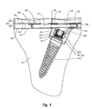
- implant 30 incorporating features of the present invention that is designed for mounting on tibia 12.
- implant 30 comprises a bearing assembly 32 attached to an anchor 34 that is adapted for mounting into a bone.
- bearing assembly 32 comprises a tray 36 with a bearing member 38 adapted for mounting thereon.
- Anchor 34 projects down from tray 36, and means for securing tray 36 to anchor 34 are provided.
- the means for securing comprises a fastener 40.
- tray 36 has a top surface 42 and an opposing bone apposition surface 44 with a perimeter edge 46 extending therebetween.
- Top surface 42 and bone apposition surface 44 are substantially flat and extend between a first end 48 and an opposing second end 50.
- a notch 51 extends between top surface 42 and bone apposition surface 44 and is formed on perimeter edge 46 at a substantially central location between opposing ends 48 and 50.
- Top surface 42 is configured to receive bearing member 38.
- a first channel 52A and a second channel 52B are formed on top surface 42.
- First channel 52A is recessed on top surface 42 so as to extend from perimeter edge 46 at second end 50 to toward first end 48.
- first channel 52A has a tapered, substantially V-shaped configuration.
- First channel 52A is bounded by a substantially flat floor 54 having a sidewall 56 upstanding therefrom.
- Sidewall 56 comprises a recess groove 58 which extends along floor 54 and an outwardly projecting lip 60 which projects along top surface 42.
- the opposing sidewalls 56 of channel 52A form a mortise or guide to receive and secure a key projecting down from bearing member 38 as will be discussed below in greater detail.
- Second channel 52B is spaced apart from first channel 52A but also extends from second end 50 to toward first end 48 of tray 36. In contrast to first channel 52A, however, second channel 52B continuously extends along perimeter edge 46. Common elements between channels 52A and 52B are identified by like reference characters. In alternative embodiments, it is appreciated that tray 36 can be formed with only one channel or three or more channels. Furthermore, the size, position, and configuration of the various channels can be varied. For example, second channel 52B can have the same configuration as first channel 52A. The general concept is that the channels are configured to that they can receivably engage bearing member 38. In this regard, side wall 56 can also have a variety of different configurations.
- Bone apposition surface 44 of tray 36 is configured to sit on the tibial plateau and typically has a configuration complementary thereto.
- bone apposition surface 44 can be substantially flat or can be curved such as having a convex curvature or concave curvature.
- grooves can be formed on bone apposition surface 44 and/or projections can be formed extending from bone apposition surface 44.
- the projections can comprise fins, sharpened spikes, or the like.
- Such projections can be configured to penetrate into the bone or to be received within slots formed on the tibial plateau.
- the projections can also serve to strengthen tray 36 by increasing the bending moment of inertia of tray 36. It is also appreciated that one or more pockets can be formed on bone apposition surface 44 in which a porous bone ingrowth material can be disposed.
- Tray 36 also bounds an opening 62 which extends completely through tray 36 between top surface 42 and bone apposition surface 44. Opening 62 is bounded by a sidewall 64 extending between top surface 42 and bone apposition surface 44. In the depicted embodiment opening 62 is large enough for all of anchor 34 to completely pass through opening 62. Although opening 62 is depicted as generally rectangular in shape, other shapes may alternatively be used, so long as opening 62 allows anchor 34 to be received into opening 62, as discussed below. By way of example and not limitation, opening 62 can be generally circular, oval, polygonal, irregular or any other shape. In the depicted embodiment opening 62 is shown being disposed at or toward second end 50 of tray 36. However, it is appreciated that opening 62 can alternatively be placed at or toward first end 48 or at other locations.
- a first passageway 66 and a second passageway 68 are horizontally formed in tray 36 so as to communicate with opening 62.
- Passageways 66 and 68 are formed to receive and secure the means for securing tray 36 to anchor 34.
- One embodiment of such means comprises fastener 40 as depicted in Figure 5 .
- Alternative means for securing are discussed below.
- First passageway 66 is bounded by an internal surface 70 that extends between perimeter edge 46 at the second end 50 of tray 36 to a sidewall 72 of opening 62. As a result, first passageway 66 forms a tunnel that is open at opposing ends.
- Second passageway 68 is bounded by an internal surface 76 and extends a distance from a medial sidewall 74 of opening 62 to toward first end 48 of tray 36. Second passageway 68 terminates at a closed distal end 78. Although depicted as terminating within tray 36, it is appreciated that second passageway 68 may alternatively extend to perimeter edge 46 at the first end 48 of tray 36.
- First and second passageways 66 and 68 have a height h and width w that are substantially constant along the entire length of both passageways.
- passageways 66 and 68 are shaped as slots with rounded side surfaces 80.
- side surfaces 80 are alternatively shaped, such as being squared off, trapezoidal or the like.
- First and second passageways 66 and 68 are longitudinally and vertically aligned to be able to receive fastener 40 when fastener 40 is inserted into tray 36 through first passageway 66, as shown in Figure 5 .
- first and second passageways 66 and 68 are depicted as slots, it is appreciated that other passageway shapes may alternatively be employed in other embodiments depending on the means provided for locking tray 36 to anchor 34.
- first and second passageways 66 and 68 can be round, oval or rectangular when viewed transversally.
- First and second passageways 66 and 68 can have internal surfaces 70 that are smooth or threaded.
- first and second passageways 66 and 68 can be disposed on the first end 48 of tray 36 if opening 62 is formed on the first end 48 of tray 36.
- First and second passageways 66 and 68 can also be tapered to allow for a greater press-fit connection with fastener 40. In any event, first and second passageways 66 and 68 are shaped to be able to receive the means for securing tray 36 to anchor 34.
- bearing member 38 comprises a top articular surface 82 and a bottom surface 84 which each extend between a first end 86 and an opposing second end 88.
- a perimeter edge 87 extends between top articular surface 82 and bottom surface 84 with a notch 79 being formed thereon.
- Top surface 82 is configured to interact with a femoral component.
- top surface 82 has a pair of spaced apart concave pockets 83A and 83B that are each adapted to receive a condyle from a femoral component.
- top surface 82 can have a variety of different configurations depending on the design for the corresponding implant that is to interact with top surface 82.
- Bottom surface 84 of bearing member 38 has a configuration substantially complementary to top surface 42 of tray 36.
- bottom surface 84 includes a substantially flat floor 81 having a pair of elongated keys 90A and 90B projecting therefrom.
- Key 90A has a configuration substantially complementary to channel 52A ( Figure 4 ) of tray 36 and includes a sidewall 92 extending from floor 81 to an end face 85.
- Sidewall 92 has a recessed groove 93 extending along floor 81 and an outwardly projecting lip 95 extending along end face 85.
- Sidewall 92 of key 90A is substantially complementary to sidewall 56 of channel 52A such that key 90A forms a tenon that can slide into channel 52A to form a secure, releasable connection therewith.
- An elongated second key 90B also projects from floor 81 and has a sidewall 92. Key 90B is configured to slide into channel 52B of tray 36 and engage with sidewall 56 thereof, thereby further securing bearing member 38 to tray 36. Alternative embodiments as discussed with tray 36 are also applicable to bearing member 38.
- Channels 52A and B and keys 90A and B are one embodiment of means for connecting bearing member 38 to tray 36.
- different techniques such as snap fit, press fit, or mechanical connector can be used to secure bearing member 38 and tray 36 together.
- Bearing member 38 may be of any suitable biocompatible material.
- bearing member 38 is comprised of a polymeric material although composites, metals, and other materials can also be used.
- anchor 34 comprises a keel 94 with a stem 96 mat projects downward therefrom.
- a locking nut 98 is used to secure stem 96 to keel 94.
- Anchor 34 is used to secure implant 30 to proximal end 10 of tibia 12.
- keel 94 comprises an upper portion 100 that terminates at a top surface 104 and a lower portion 102 that terminates at a bottom surface 105.
- keel 94 also has an interior surface 109 that bounds a bore 126 extending through keel 94 between top surface 104 and bottom surface 105.
- Radially inwardly projecting from interior surface 109 at a location toward bottom surface 105 is an annular flange 111.
- Flange 111 forms a seat against which locking nut 98 can bias.
- upper portion 100 is used to mount and secure keel 94 to tray 36 while lower portion 102 is used to mount and secure keel 94 to stem 96.
- upper and lower portions 100 and 102 are integrally formed. In other embodiments upper and lower portions 100 and 102 can be separate and discrete components that are connected together.
- Upper portion 100 is configured to fit within opening 62 in tray 36 and can selectively pass therethrough if desired.
- Upper portion 100 is shown having a transverse cross section that is substantially complementary to the transverse cross section of opening 62. That is, upper portion 100 is rectangularly shaped when viewed perpendicularly to top surface 104 so as to substantially match the shape of opening 62.
- Top surface 104 of upper portion 100 is substantially planar so that it can sit flush with top surface 42 of tray 36.
- upper portion 100 has a sidewall 106 that is substantially the same thickness as tray 36 at opening 62.
- a third passageway 110 transversely extends all the way through upper portion 100 of keel 94 so as to intersect with bore 126.
- third passageway 110 is bounded by an internal surface 112 and extends from a first opening 114 on sidewall 106 of keel 94 to a second opening 118 on the opposing side of keel 94.
- Third passageway 110 is sized and shaped to substantially align with first and second passageways 66 and 68 of tray 36 when upper portion 100 of keel 94 is received within opening 62 of tray 36. Aligned passageways 66, 68, and 110 combine to form a contiguous passageway which can receive fastener 40.
- third passageway 110 has substantially the same height h and width w as first and second passageways 66 and 68.
- Third passageway 110 is depicted as a slot with rounded side surfaces to match first and second passageways 66 and 68. It is appreciated that other passageway shapes may alternatively be employed in third passageway in other embodiments to match alternatively shaped first and second passageways 66 and 68.
- third passageway 110 can be substantially round, oval or rectangular when viewed transversally.
- Third passageway 110 can have walls that are smooth or threaded to match first and second passageways 66 and 68.
- lower portion 102 of keel 94 is used to mount and secure keel 94 to stem 96.
- Lower portion 102 angles down from upper portion 100.
- Lower portion 102 is substantially rectangular where it connects to upper portion 100 and transitions to being substantially cylindrical in shape at a bottom end 122.
- a central longitudinal axis 113 extends through lower portion 102 and the portion of bore 126 disposed therein.
- lower portion 102 is formed so that an inside angle ⁇ is formed between top surface 104 of keel 94 and longitudinal axis 113 that is less than 80° and more commonly less than 70° or 60°.
- lower portion 102 and bore 126 can be positioned so that the angle ⁇ is 90°.
- stem 96 is an elongated member having a proximal end 134 and an opposing distal end 136.
- Stem 96 includes a head 130 formed at proximal end 134 and a shank 132 projecting from head 130.
- Shank 132 tapers to a point at distal end 136 and has threads formed thereon so that shank 132 can be threaded or screwed into tibia 12 so as to securely engage tibia 12.
- shank 132 has a larger outer diameter than head 130 so that an annular shoulder 117 is formed thereat.
- Head 130 is threaded so as to enable locking nut 98 to be screwed thereon, as described below.
- proximal end 134 terminates at a terminal end face 119 in which a socket 121 is formed.
- Socket 121 is non-circular to that a driver (not shown) can be received within socket 121 and then rotated so as to rotate stem 96.
- socket 121 has a polygonal configuration although other non-circular shapes can also be used.
- a stem having a polygonal or other non-circular transverse cross section can project from end face 119 for engaging with a driver.
- slots or other structures can be formed on end face 119 for engaging with a driver.
- Locking nut 98 comprises a nut with internal threads that match the threads of head 130 of stem 96, thus allowing locking nut 98 to be able to be screwed onto head 130.
- One embodiment of the present invention also includes means for coupling a driver to locking nut 98.
- locking nut 98 has a plurality of cut-outs or ridges 138 formed on a proximal end thereof to allow nut 98 to be manually screwed onto head 130 by using a tool with matching cut-outs or ridges that engage with cut-outs or ridges 138. It is appreciated that a variety of different structures can be formed on nut 98 to engage with a driver.
- the exterior surface of nut 98 can have a polygonal configuration to match with a driver.
- head 130 of stem 96 has an outer diameter d3 that is less than inner diameter d2 of annular flange 111 of keel 94 such that head 130 can fit through annular flange 111 while shoulder 117 of stem 96 biases against flange 111.
- Locking nut 98 has an outer diameter d5 that is smaller than the diameter d1 of bore 126 but greater than the inner diameter d2 of annular flange 111 so that locking nut 98 can be screwed onto threaded head 130 and biased against annular flange 111, thereby securely connecting stem 96 to keel 94.
- means for locking tray 36 to anchor 34 can be permanent, releasable, or removable.
- means for securing comprises fastener 40.
- Fastener 40 includes generally planar top and bottom surfaces 140 and 142 extending between a proximal end 144 and a spaced-apart distal end 146.
- a perimeter sidewall 148 extends between top surface 140 and bottom surface 142.
- Fastener 40 has a height and width that are equal to or slightly less than the height and width, respectively, of passageways 66, 68, and 110 such that when distal end 146 of fastener 40 is inserted into first passageway 66 and pushed toward the first end 48 of tray 36, fastener 40 passes through first passageway 66, third passageway 110 of keel 94 (if keel 94 is inserted into opening 62), and into second passageway 68, establishing a snug, press-fit connection.
- fastener 40 is described above as having a uniform height and width along the length of fastener 40, it is appreciated that in some embodiments top surface 140 and bottom surface 142 lie in diverging planes resulting in fastener 40 being tapered along the length thereof. Similarly, in some embodiments, the width of fastener 40 is tapered toward the distal end 146 of fastener 40. Tapering of fastener 40 aids in insertion of fastener 40 while increasing the frictional engagement between the various parts.
- a threaded bore 150 is formed in sidewall 148 at the proximal end 144 of fastener 40 to aid in the insertion and extraction of fastener 40. That is, an insertion/extraction tool (not shown) with a corresponding threaded end can be screwed into bore 150 to aid in the insertion and/or extraction of fastener 40 into or out of tray 36 and keel 34.
- fastener 40 can be generally round, oval or rectangular when viewed transversally.
- a threaded fastener such as a bolt or screw, can be passed through tray 36 and keel 34 so as to secure the members together.
- the fastener need not extend all the way through keel 94 but can terminate therein.
- second passageway 68 can be eliminated.
- wide fastener 40 can be replaced with two or more narrower fasteners, such as in the form of elongated pins, that each separately extend through tray 36 and keel 34.
- first and second passageways 66 and 68 of tray 36 and third passageway 110 of keel 94 must be adapted to receive the type of means used for locking.
- bearing member 38 is typically formed from a polymeric biocompatible material. While the other components of implant 30 are also made from a biocompatible material, they are typically made from a metal such as titanium, titanium alloy, or stainless steel. Other materials, such as ceramics, composites, plastics or the like, can also be used.
- FIG. 9 in conjunction with Figure 3 , one method of assembly and implantation of implant 30 on tibia 12 will now be described.
- the articulation surface of the bone must be prepared before an articular implant can be mounted thereon.
- the proximal end of tibia 12 is transversely resected so as to remove the tibial condyles and form a substantially flat tibial plateau 160.
- stem 96 is screwed or otherwise secured into tibia plateau 160 at the proximal end of the tibia 12.
- the predrilled hole is formed at an orientation complementary to the angle orientation of keel 94.
- a driver is coupled with socket 121 to assist in mounting stem 96.
- keel 94 is placed over the top of stem 96 such that head 130 is received into bore 126. Head 130 is passed through flange 111 so that shoulder 117 biases against flange 111. Locking nut 98 is then inserted into bore 126 from top surface 104 of keel 94, and securely screwed onto threaded head 130 using a driver as previously discussed. When tightened on threaded head 130, locking nut 98 biases against the opposing side of annular flange 111, thereby rigidly connecting keel 94 to stem 96 and preventing keel 94 from moving with respect to stem 96. At this point, anchor 34, consisting of keel 94 and stem 96 rigidly connected by locking nut 98, is secured to tibia 12.
- tray 36 is placed on the proximal end of tibia 12 and secured to anchor 34. In the depicted embodiment, this is accomplished by placing tray 36 on top of anchor 34 such that upper portion 100 of keel 94 is received into opening 62 of tray 36. The positioning is made so that first and second passageways 66 and 68 of tray 36 are aligned with third passageway 110 in keel 94. In this position, bone apposition surface 44 of tray is sitting upon tibial plateau 160 of tibia 12. Here it is noted that care is taken to secure keel 94 in the proper orientation on stem 96 so that tray 36 is properly orientated on tibial plateau 160 when coupled with keel 94. If necessary, locking nut 98 can be loosened and the orientation of keel 98 adjusted without having to loosen or adjust stem 96.
- first, second, and third passageways 66, 68 and 110 are aligned, the distal end 146 of fastener 40 is inserted into first passageway 66 at the second end 50 of tray 36. Fastener is then advanced into third passageway of keel 92 and second passageway of tray 36, thereby forming a press-fit connection between fastener 40 and the internal surfaces 70, 76, and 112 of passageways 66, 68, and 110, respectively.
- An insertion tool may be removably screwed into or otherwise attached to bore 150 in the proximal end 144 of fastener 40 to aid in the insertion of fastener 40, but this is not required.
- fastener 40 When fully inserted, fastener 40 is fully disposed within the combination of passageways 66, 68, and 110. This rigidly secures tray 36 to anchor 34. If an insertion tool was used to insert fastener 40, it is unscrewed or otherwise disconnected from bore 150 of fastener 40.
- bearing member 38 is then secured to tray 36 to form bearing assembly 32.
- this is accomplished by biasing bottom surface 84 of bearing member 38 against top surface 42 of tray 36 and sliding bearing member 38 over tray 36 until keys 90A and B on the bottom surface 84 of bearing member 38 are snugly fit into channels 52A and B on top surface 42 of tray 36 (see Figures 4 and 6 ).
- Other methods known in the art alternatively can be used to secure bearing member 38 to tray 36 to form bearing assembly 32.
- bearing member 38 can be secured to tray 36 before or after tray is mounted to anchor 34.
- bearing member 38 can be integrally or permanently mounted to tray 36.
- tray 36 can first be positioned on tibial plateau 160. After tray 36 is positioned, stem 96 can be passed through opening 62 in tray 36 and then advanced into tibial 12. Keel 94 is then passed into opening 62 of tray 36 and over head 130 of stem 96. Locking nut 98, as described above, is then used to secure keel 98 to stem 96. Fastener 40 is then used to rigidly secure tray 36 to anchor 34, as described above. Finally, bearing member 38 is mounted to tray 36.
- opening 62 extends all the way through tray 36. Rather, opening 62 need only extend from bone apposition surface 44 to first passageway 66 and second passageway 68.
- FIG. 10 and 11 depicted in Figures 10 and 11 is an alternative embodiment of an inventive total condylar implant 230 (shown without bearing member 38) which incorporates features of the present invention.
- Like elements between implant 30 and implant 230 are identified by like reference characters.
- Implants 30 and 230 are substantially similar except that as opposed to tray 36 having an opening 62 which extends completely through tray 36 between top surface 42 and bone apposition surface 44, the opening 232 in tray 234 does not extend through top surface 42. Opening 232 is formed on bone apposition surface 44 and is bounded by a substantially flat floor 236 having sidewall 64 extending therefrom. First passageway 66 and second passageway 68 communicate with opening 232. When anchor 34 is mounted to tray 234, keel 94 abuts floor 236. In addition to that previously discussed, however, having opening 62 extend all the way through tray 36 can provide added benefits. For example, having opening 62 extend through tray 36 enables tray 36 to be used as a template for the mounting of anchor 34 on tibial plateau 160 and can assist in making proper alignment with anchor 34.
- Tray 36 and bearing member 38 as depicted and discussed above are designed for use with a total joint arthroplasty. That is, tray 36 and bearing member 38 form part of a total condylar implant. Alternative embodiments of the present invention, however, can also be used in partial joint arthroplasty.
- a uni-condylar implant 200 for replacing only a single condyle at the proximal end of tibia 12.
- Like elements between total condylar implant 30 and uni-condylar implant 200 are identified by like reference characters.
- Implants 30 and 200 are substantially similar except that as opposed to bearing assembly 32, comprising tray 36 and bearing member 38, being sized to replace both the medial and lateral condyles at the proximal end of tibia 12, bearing assembly 202, comprising tray 204 and bearing member 206, is sized to replace only one of the condyles. Because of the smaller size of tray 204, second passageway 208 is shorter than second passageway 68 and fastener 210 is correspondingly shorter than fastener 40 so as to not protrude from first passageway 66 when fully inserted into second passageway 208. The same steps discussed above for mounting total condylar implant 30 can also be used for mounting uni-condylar implant 200. In mounting uni-condylar implant 200, however, only one of the condyles is resected from tibia 12.
- opening 62 remains the same size for both trays and the same anchor 34 can be used with both implants 30 and 200.
- This allows uni-condylar implant 200 to be replaced with total condylar implant 30 using the same anchor 34.
- uni-condylar implant 200 it may only be necessary to mount a uni-condylar implant 200 where only one of the condyles of a knee joint has been damaged. After subsequent ware or damage to the knee joint, however, it may be necessary to replace uni-condylar implant 200 with total condylar implant 30.
- bearing assembly 202 is simply disconnected from anchor 34. To accomplish this, the insertion tool is screwed into bore 150 on the proximal end 144 of fastener 40. Using the tool, fastener 40 is then completely retracted out of tray 204, thereby disengaging from passageways 66, 68, and 110. Once fastener 40 is removed, bearing assembly 202 is lifted off of anchor 34 and removed. Anchor 34, however, remains secured to tibia 12. After resecting the remaining condyle on tibia 12, total condylar bearing assembly 32 is then positioned on the proximal end of the tibia 12 and connected to anchor 34 using fastener 40 in the same manner as previously discussed.
- stem 96 of both implants 30 and 200 is typically sloped relative to corresponding tray 36, 204.
- stem 96 is more centrally mounted on tibia 12.
- the same stem 96 can also be used for mounting total condylar implant 30 without having to reset stem 96.
- the present invention can also be used in association with replacing one or both condyles at the distal end of a femur.
- a total condylar implant 300 for replacing both condyles at the distal end of a femur 302 which incorporates features of the present invention.
- Like elements between total condylar implant 30 and total condylar implant 300 are identified by like reference characters.
- Implant 300 comprises a bearing assembly 304 attached to anchor 34 that is adapted for mounting into femur 302.
- Bearing assembly 304 comprises a tray 306 and a bearing member 308 adapted for mounting thereon.
- Bearing member 304 is configured to replace the condyles resected at the distal end of femur 302.
- Bearing member 308 can be mounted to tray 306 in various ways.
- bearing member 308 and tray 306 can have matching mortices and tenons formed thereon which secure bearing member 308 to tray 306.
- Other methods of mounting can alternatively be used, such as using adhesives, snap fit connections, or other methods known in the art.
- bearing member 308 and tray 306 can be integrally formed of the same material.
- Anchor 34 projects away from tray 306, and is adapted to be inserted and secured in the distal end of femur 302.
- Fastener 40 secures tray 306 to anchor 34 in the same manner as described above with regard to tibial implant 30. Similar to tray 36, tray 306 also bounds an opening 310 which extends completely through tray 306 and is large enough for all of anchor 34 to completely pass through. Similar to previous embodiments of the current invention, once anchor 34 has been implanted and secured to femur 302, bearing assembly 304 can be mounted, removed, and replaced without removing anchor 34 by using fastener 40 in the manner previously discussed.
- Embodiments of the present invention have been disclosed relating to both surfaces of a hinge type of joint, namely the tibia and femur. It is appreciated that the present invention can also be used with other hinge type joints, such as the elbow, or ball and socket joints, such as the hip joint.
- a pelvis 400 that would normally include an acetabular socket 402 having an articulating surface.
- acetabular socket 402 has been resected to form a resected articulating surface 404 and an implant 406 which incorporates features of the present invention has been mounted to pelvis 400 to replace acetabular socket 402.
- Implant 406 comprises a bearing assembly 408 attached to an anchor 410 that is adapted for securing into pelvis 400. Similar to the acetabular socket that implant 406 is replacing, bearing assembly 408 is configured to receive a ball 411 at the proximal end of a femur 413 or a femoral implant. Towards this end, bearing assembly 408 comprises a roughly hemispherically shaped tray 412 (also known as a cup) and a bearing member 414 adapted for mounting thereon.
- Tray 412 has a concave inside surface 416 and an opposing convex outside surface 418.
- Bearing member 414 mounts onto the inside surface 416 of tray 412, while outside surface 418 of tray 412 is disposed against pelvis 400.
- Bearing member 414 can be mounted to tray 412 in various ways. For example, similar to previously described embodiments, bearing member 414 and tray 412 can have matching mortices and tenons formed thereon which secure bearing member 414 to tray 412. Other methods of mounting can alternatively be used, such as using adhesives, snap fit connections, or other methods known in the art.
- tray 412 has an opening 420 bounded by a sidewall 422 which extends completely through tray 412 between inside surface 416 and outside surface 418.
- opening 420 is large enough for all of anchor 410 to completely pass through opening 420. Because of this, as with previously discussed embodiments of the current invention, once anchor 410 has been implanted and secured to pelvis 400, bearing assembly 408 can be mounted, removed, and replaced without removing anchor 410, as discussed below.
- Anchor 410 projects away from outside surface 418 of tray 412 and is adapted to be inserted and secured in pelvis 400.
- Means for securing tray 412 to anchor 410 are provided. Similar to anchor 34, anchor 410 is used to secure implant 406 to pelvis 400.
- tray 412 Due to the shape of tray 412, it would be difficult to use the same type of fastener to secure tray 412 to anchor 410. That is, because tray 412 is rounded and fits within acetabular socket 402, it would be difficult for a physician to gain easy access to the side of implant 406 to push in or pull out a fastener from the side of anchor 410. Therefore an alternative means for securing is used with implant 406 according to the present invention.
- anchor 410 is aligned along a longitudinal axis 430 and comprises a keel 424 with a stem 426 that projects outward therefrom.
- a locking screw 428 is used as a fastener to secure keel 424 to stem 426.
- keel 424 has an external sidewall 432 which extends between a top surface 434 at a proximal end 436 and a spaced apart bottom surface 438 at a distal end 440.
- Top surface 434 and bottom surface 438 are generally planar- In one embodiment, keel 424 is positioned so that top surface 434 is generally orthogonal to axis 430, while bottom surface 438 is generally not orthogonal to axis 430.
- an angle ⁇ is formed between bottom surface 438 and axis 430 that is typically between about 15 degrees and about 75 degrees, with about 30 degrees to about 60 degrees being more common. Other angles can also be used.
- Keel 424 also has an interior surface 442 that bounds a smooth bore 444 extending through keel 424 between top surface 434 and bottom surface 438 along axis 430. The bore is enlarged at proximal end 436 of keel 424 to accommodate a head of locking screw 428, as discussed below.
- Stem 426 is similar to stem 96, except that stem 426 has no head formed thereon. Instead, stem 426 has a top surface 446 formed at a proximal end 448 thereof from which a threaded shank 449 extends. Top surface 446 of stem 426 is shaped to match bottom surface 438 of keel 424. That is, top surface 446 of stem 426 is generally planar and generally at the same angle ⁇ to axis 430 as is bottom surface 438 of keel 424. Stem 426 has an interior surface 450 that bounds a passageway or bore 452 extending into stem 426 from top surface 446 along axis 430.
- Bore 452 includes internal threads 454 to engage locking screw 428 and is generally longitudinally aligned with bore 444 of keel 424 along axis 430. Similar to shank 132, shank 449 tapers to a point at a distal end 456 of stem 426 along axis 430 and has threads formed thereon so that shank 449 can be threaded or screwed into pelvis 400 so as to securely engage pelvis 400.
- Locking screw 428 extends between a proximal end 458 and a spaced apart distal end 460, a head 462 being formed at proximal end 458 and external threads 464 being formed at distal end 460. External threads 464 match the internal threads 454 of bore 452, thus allowing locking screw 428 to be able to be screwed into stem 426.
- Formed on head 462 are means for engagement, such as, for example, a slot, a socket, or other configurations known in the art.
- the use of a screwdriver, Allen wrench, or other type of tool known in the art for rotating a screw and corresponding to the means for engagement can be used to screw locking screw 428 into stem 426.
- tray 412 is placed over stem 426 such that opening 420 aligns with top surface 446 of stem 426.
- Tray 412 is then mounted onto pelvis 400 such that proximal end 448 of stem 426 is at least partially disposed within opening 420.
- Keel 424 is placed within opening 420 such that distal end 440 of keel 424 biases against proximal end 448 of stem 426 so that the angle of bottom surface 438 of keel 424 matches the angle of top surface 446 of stem 426.
- distal end 460 of locking screw 428 is then inserted through bore 444 of keel 424 and screwed into bore 452 of stem 426.
- the external threads 464 of locking screw 428 engage the internal threads 454 within bore 452, pulling locking screw 428 further towards distal end 456 of stem 426.
- head 462 of locking screw 428 biases against the enlarged portion of bore 444 at proximal end 436 of keel 424 and causes keel 424 to push against stem 426.
- bore 444 of keel 424 can be slightly offset longitudinally from bore 452 of stem 426. Then, when locking screw 428 is screwed into stem 426, the longitudinal offset will cause distal end 440 of keel 424 and proximal end 448 of stem 426 to push outward against sidewall 422 of tray 412 in opposite directions, thereby securing tray 412 to stem 426.
- the aforementioned methods of securing and removing tray 412 from pelvis 400 allows for easy replacement of implant 406 using the same anchor 410 when, for example, a tray is damaged, or a different sized tray is desired (due to growth in a child, for example).
- the present invention can also be used with other joints within the body, such as the shoulder, elbow, ankle, wrist, or the like.
- the present invention has a number of benefits.
- the mechanism for mounting it can be relatively easy to adjust positioning or orientation of the tray and bearing member.
- the present invention also permits a single anchoring system to be used for both a uni-condylar implant and a total condylar implant.
- the switch between the two implants can be made without having to remove the anchor from the bone.
- the inventive system can decrease material costs, reduce the surgical time for the procedure, and minimize bone damage.
Abstract
Description
- The present invention relates to prosthetic joints and, more particularly, to modular interchangeable bone implants to replace articular bone surfaces.
- The human body has a variety of movable orthopedic joints such as the knee joint, hip joint, shoulder joint, and the like. These joints are formed by the intersection of two bones. The intersecting end of each bone has one or more condyles consisting of a smooth articular surface that is comprised of cartilage. For example, the knee joint comprises two generally rounded condyles, i.e., lateral and medial condyles that are located at the lower or distal end of the femur. These femoral condyles are disposed above corresponding lateral and medial condyles located at the upper or proximal end of the tibia.
- As a result of injury, wear, arthritis, disease or other causes, it is occasionally necessary to replace all or part of an orthopedic joint with an artificial implant. This procedure is referred to as a joint replacement or arthroplasty. For example, a total knee arthroplasty comprises cutting off or resecting the femoral condyles at the distal end of the femur and the tibial condyles at the proximal end of the tibia. Complementary artificial implants, referred to as total condylar implants, are then mounted on the distal end of the femur and the proximal end of the tibia. Where only a portion of a joint is damaged, a partial joint arthroplasty can be performed. In this procedure, one or more artificial implants replace only a portion of a joint. For example, where only one femoral or tibial condyle of the knee joint has been injured, only one of the injured lateral or medial femoral condyles is resected. The corresponding one of the lateral or medial tibial condyles is also resected. Implants replacing only a single condyle, referred to as uni-condylar implants, are mounted on the resected area of the femur and tibia.
- One example of a total condylar implant that can be used on the tibia is disclosed in
US Patent No. 4,936,853 . The implant comprises a tibial stem portion, a tibial tray portion, an interchangeable modular articulating surface member which is removably attached to the tibial tray portion, and a femoral portion adapted to cooperatively bear upon the articulating surface. - Although joint replacement is now a common procedure that has met with popular success, conventional implants and related mounting techniques have significant shortcomings. For example, one problem with conventional joint implants and related techniques for mounting is that it can be difficult to fit, adjust, and/or exchange different implants during the fitting stage. That is, implants come in a variety of different sizes, shapes, and configurations- During the joint replacement procedure, the surgeon may often test a variety of different sized implants to determine the best fit and alignment. As conventional implants are screwed into or pounded onto the bone during placement, the fitting, adjustment, and/or replacement of different conventional implants can be difficult and potentially damaging to the bone.
- Another shortcoming with current implants is an inability to easily replace the implant once the implant has been installed. For example, as mentioned above, a partial joint arthroplasty may be required, and a uni-condylar implant installed. Months or years later, the rest of the joint may deteriorate and the uni-condylar implant must be replaced with a total condylar implant. This occurs frequently with the knee. Using current prostheses and methods, replacing a uni-condylar implant with a total condylar implant requires removing the entire uni-condylar implant from the bone (including the anchoring system), drilling or otherwise creating a new hole in the bone to anchor the total joint implant, then installing the total joint implant with a new anchor. Because a new anchoring hole and anchor are required, more bone must be drilled into or otherwise removed, causing more pain for the patient, an increased possibility of infection, a longer recovery time, and generally more risk.
- Accordingly, what is needed are implants for mounting the implants on an articular surface of a joint which enable easier fitting, alignment, testing, and/or replacement of implants. What is also needed are implants which enable easy replacement of uni-condylar implants with total condylar implants.
- Various embodiments of the present invention will now be discussed with reference to the appended drawings. It is appreciated that these drawings depict only typical embodiments of the invention and are therefore not to be considered limiting of its scope.
-
Figure 1 is a perspective view of the proximal end of a tibia; -
Figure 2 is a perspective view of a total condylar implant according to one embodiment of the present invention that can be placed on the proximal end of the tibia shown inFigure 1 ; -
Figure 3 is an exploded perspective view of the implant shown inFigure 2 ; -
Figure 4 is a top perspective view of the tray of the implant shown inFigure 3 ; -
Figure 5 is a cross-sectional top view of the tray shown inFigure 4 , with a fastener inserted therein; -
Figure 6 is a bottom perspective view of the bearing member of the implant shown inFigure 3 ; -
Figure 7 is a cross sectional side view of the keel shown inFigure 3 ; -
Figure 8 is a cross-sectional side view of an anchor used in the implant shown inFigure 3 ; -
Figure 9 is a cross sectional side view of the implant shown inFigure 2 mounted on the tibia shown inFigure 1 ; -
Figure 10 is a perspective view of a total condylar implant (shown without a bearing member) according to an alternative embodiment of the present invention; -
Figure 11 is a bottom perspective view of a tray used in the implant shown inFigure 10 ; -
Figure 12 is a perspective view of an uni-condylar implant according to one embodiment of the present invention that can be placed on the proximal end of the tibia shown inFigure 1 ; -
Figure 13 is a cross-sectional top view of a tray used in the uni-condylar implant shown inFigure 12 ; -
Figure 14 is a cross-sectional side view of an alternative embodiment of an inventive implant mounted on the distal end of a femur with a fastener partially inserted; -
Figure 15 is a cross-sectional side view of another alternative embodiment of an inventive implant mounted on a pelvis; -
Figure 16 is a cross-sectional side view of a partially assembled anchor used in the implant shown inFigure 15 ; and -
Figure 17 is a cross-sectional side view of the anchor shown inFigure 15 . fully assembled. - The present invention relates to implants for mounting at an articulation surface of an orthopedic joint. As used in the specification and appended claims, the terms "articulation surface" and "natural articulation surface" are broadly intended to include all natural articular surfaces of a bone forming a portion of an orthopedic joint and all articulation wear surfaces of a bone forming a portion of an orthopedic joint which are produced as a result of wear, trauma, disease, or other causes which remove all or a portion of the natural articular surface.
- It is appreciated that the implants of the present invention can be used for mounting an implant on virtually any articulation surface of any orthopedic joint in a human or other mammal. By way of example and not by limitation, the implants of the present invention can be used in association with resurfacing an articulation surface of a knee joint, ankle joint, hip joint, shoulder joint, elbow joint, wrist joint, interphalangeal joint, or other joints. As such, the implants can be mounted on the proximal end and distal end of the femur, tibia, humerus, radius, and ulna, and on the articular surfaces of the scapula, pelvis, bones within the foot and hand, and other bone articular surfaces. Likewise, the implants of the present invention can be used in facilitating a partial joint arthroplasty or a total joint arthroplasty.
- In one embodiment of the present invention, the implants are designed to be modular such that either the articulation bearing surface of the implant can be positioned on the bone after an anchor is inserted into the bone or the anchor can be inserted into the bone after the articulation bearing surface of the implant has been positioned on the bone. This ability allows for greater ease in adjustment and fitting of the implant at the time of initial placement and for greater ease in replacement of the implant.
- Set forth below are several embodiments of the present invention used in association with replacing one or both condyles at the proximal end of a tibia. Alternative embodiments used with a femur and a hip are also set forth. It is again noted that these embodiments are only given by way of example and that one skilled in the art based on the teachings provided herein would be able to use corresponding implants to prepare and/or mount an implant on other joint articulation surfaces.
- Depicted in
Figure 1 is aproximal end 10 of atibia 12.Proximal end 10 has alateral side 14 and amedial side 16 which each extend between ananterior side 18 and aposterior side 20.Proximal end 10 further comprises alateral condyle 22 and amedial condyle 24.Lateral condyle 22 terminates proximally at alateral facet 26 of a superior articular surface oftibia 12 whilemedial condyle 24 terminates proximally atmedial facet 28 of a superior articular surface oftibia 12. - Although
tibia 12 shown inFigure 1 corresponds to a left leg, it is appreciated that the tibia of the right leg has a complimentary configuration and that the apparatus of this specific example are equally applicable thereto. Thus, while reference is made to "medial" and "lateral" objects or directions, it is appreciated that these references would be reversed when using embodiments of the current invention with the right leg. - Depicted in
Figure 2 is one embodiment of aninventive implant 30 incorporating features of the present invention that is designed for mounting ontibia 12. In general,implant 30 comprises a bearingassembly 32 attached to ananchor 34 that is adapted for mounting into a bone. More specifically, as depicted inFigure 3 , bearingassembly 32 comprises atray 36 with a bearingmember 38 adapted for mounting thereon.Anchor 34 projects down fromtray 36, and means for securingtray 36 to anchor 34 are provided. In the depicted embodiment, the means for securing comprises afastener 40. These elements, including alternative means for securing, are discussed in more detail below. - As depicted in
Figure 4 ,tray 36 has atop surface 42 and an opposingbone apposition surface 44 with aperimeter edge 46 extending therebetween.Top surface 42 andbone apposition surface 44 are substantially flat and extend between afirst end 48 and an opposingsecond end 50. Anotch 51 extends betweentop surface 42 andbone apposition surface 44 and is formed onperimeter edge 46 at a substantially central location between opposing ends 48 and 50. -
Top surface 42 is configured to receive bearingmember 38. Specifically, in the depicted embodiment afirst channel 52A and asecond channel 52B are formed ontop surface 42.First channel 52A is recessed ontop surface 42 so as to extend fromperimeter edge 46 atsecond end 50 to towardfirst end 48. Although not required,first channel 52A has a tapered, substantially V-shaped configuration.First channel 52A is bounded by a substantiallyflat floor 54 having asidewall 56 upstanding therefrom.Sidewall 56 comprises arecess groove 58 which extends alongfloor 54 and an outwardly projectinglip 60 which projects alongtop surface 42. As such, the opposingsidewalls 56 ofchannel 52A form a mortise or guide to receive and secure a key projecting down from bearingmember 38 as will be discussed below in greater detail. -
Second channel 52B is spaced apart fromfirst channel 52A but also extends fromsecond end 50 to towardfirst end 48 oftray 36. In contrast tofirst channel 52A, however,second channel 52B continuously extends alongperimeter edge 46. Common elements betweenchannels tray 36 can be formed with only one channel or three or more channels. Furthermore, the size, position, and configuration of the various channels can be varied. For example,second channel 52B can have the same configuration asfirst channel 52A. The general concept is that the channels are configured to that they can receivably engage bearingmember 38. In this regard,side wall 56 can also have a variety of different configurations. - As will be discussed below in greater detail, during typical use of
implant 30,proximal end 10 of tibia 12 (Figure 1 ) is resected to form a tibial plateau.Bone apposition surface 44 oftray 36 is configured to sit on the tibial plateau and typically has a configuration complementary thereto. In this regard,bone apposition surface 44 can be substantially flat or can be curved such as having a convex curvature or concave curvature. Likewise, grooves can be formed onbone apposition surface 44 and/or projections can be formed extending frombone apposition surface 44. The projections can comprise fins, sharpened spikes, or the like. Such projections can be configured to penetrate into the bone or to be received within slots formed on the tibial plateau. The projections can also serve to strengthentray 36 by increasing the bending moment of inertia oftray 36. It is also appreciated that one or more pockets can be formed onbone apposition surface 44 in which a porous bone ingrowth material can be disposed. -
Tray 36 also bounds anopening 62 which extends completely throughtray 36 betweentop surface 42 andbone apposition surface 44.Opening 62 is bounded by asidewall 64 extending betweentop surface 42 andbone apposition surface 44. In the depicted embodiment opening 62 is large enough for all ofanchor 34 to completely pass throughopening 62. Although opening 62 is depicted as generally rectangular in shape, other shapes may alternatively be used, so long as opening 62 allowsanchor 34 to be received intoopening 62, as discussed below. By way of example and not limitation, opening 62 can be generally circular, oval, polygonal, irregular or any other shape. In the depicted embodiment opening 62 is shown being disposed at or towardsecond end 50 oftray 36. However, it is appreciated that opening 62 can alternatively be placed at or towardfirst end 48 or at other locations. - Turning to
Figure 5 in conjunction withFigure 4 , afirst passageway 66 and asecond passageway 68 are horizontally formed intray 36 so as to communicate withopening 62.Passageways tray 36 to anchor 34. One embodiment of such means comprisesfastener 40 as depicted inFigure 5 . Alternative means for securing are discussed below.First passageway 66 is bounded by aninternal surface 70 that extends betweenperimeter edge 46 at thesecond end 50 oftray 36 to asidewall 72 ofopening 62. As a result,first passageway 66 forms a tunnel that is open at opposing ends.Second passageway 68 is bounded by aninternal surface 76 and extends a distance from amedial sidewall 74 of opening 62 to towardfirst end 48 oftray 36.Second passageway 68 terminates at a closeddistal end 78. Although depicted as terminating withintray 36, it is appreciated thatsecond passageway 68 may alternatively extend toperimeter edge 46 at thefirst end 48 oftray 36. - First and
second passageways second passageways fastener 40 whenfastener 40 is inserted intotray 36 throughfirst passageway 66, as shown inFigure 5 . - Although first and
second passageways tray 36 to anchor 34. By way of example and not limitation, first andsecond passageways second passageways internal surfaces 70 that are smooth or threaded. Although depicted as being disposed on thesecond end 50 oftray 36, it is also appreciated that first andsecond passageways first end 48 oftray 36 if opening 62 is formed on thefirst end 48 oftray 36. First andsecond passageways fastener 40. In any event, first andsecond passageways tray 36 to anchor 34. - With reference to
Figures 2 and6 , bearingmember 38 comprises a toparticular surface 82 and abottom surface 84 which each extend between afirst end 86 and an opposingsecond end 88. Aperimeter edge 87 extends between toparticular surface 82 andbottom surface 84 with anotch 79 being formed thereon.Top surface 82 is configured to interact with a femoral component. In the depicted embodimenttop surface 82 has a pair of spaced apart concave pockets 83A and 83B that are each adapted to receive a condyle from a femoral component. In alternative embodiments it is appreciated thattop surface 82 can have a variety of different configurations depending on the design for the corresponding implant that is to interact withtop surface 82. -
Bottom surface 84 of bearingmember 38 has a configuration substantially complementary totop surface 42 oftray 36. Specifically,bottom surface 84 includes a substantiallyflat floor 81 having a pair ofelongated keys Figure 4 ) oftray 36 and includes asidewall 92 extending fromfloor 81 to anend face 85.Sidewall 92 has a recessed groove 93 extending alongfloor 81 and an outwardly projecting lip 95 extending alongend face 85.Sidewall 92 ofkey 90A is substantially complementary to sidewall 56 ofchannel 52A such that key 90A forms a tenon that can slide intochannel 52A to form a secure, releasable connection therewith. An elongated second key 90B also projects fromfloor 81 and has asidewall 92. Key 90B is configured to slide intochannel 52B oftray 36 and engage withsidewall 56 thereof, thereby further securing bearingmember 38 totray 36. Alternative embodiments as discussed withtray 36 are also applicable to bearingmember 38. -
Channels 52A and B andkeys 90A and B are one embodiment of means for connecting bearingmember 38 totray 36. In alternative embodiments, different techniques such as snap fit, press fit, or mechanical connector can be used to secure bearingmember 38 andtray 36 together. Bearingmember 38 may be of any suitable biocompatible material. Typically, bearingmember 38 is comprised of a polymeric material although composites, metals, and other materials can also be used. - Returning to
Figure 3 .anchor 34 comprises akeel 94 with astem 96 mat projects downward therefrom. A lockingnut 98 is used to securestem 96 tokeel 94.Anchor 34 is used to secureimplant 30 toproximal end 10 oftibia 12. In general,keel 94 comprises anupper portion 100 that terminates at atop surface 104 and alower portion 102 that terminates at abottom surface 105. As depicted inFigure 7 ,keel 94 also has aninterior surface 109 that bounds abore 126 extending throughkeel 94 betweentop surface 104 andbottom surface 105. Radially inwardly projecting frominterior surface 109 at a location towardbottom surface 105 is anannular flange 111.Flange 111 forms a seat against which lockingnut 98 can bias. - Returning to
Figure 3 ,upper portion 100 is used to mount and securekeel 94 totray 36 whilelower portion 102 is used to mount and securekeel 94 to stem 96. As shown in the depicted embodiment, upper andlower portions lower portions Upper portion 100 is configured to fit within opening 62 intray 36 and can selectively pass therethrough if desired.Upper portion 100 is shown having a transverse cross section that is substantially complementary to the transverse cross section ofopening 62. That is,upper portion 100 is rectangularly shaped when viewed perpendicularly totop surface 104 so as to substantially match the shape ofopening 62. Alternative cross sectional shapes can also be used so as to match alternative shapes foropenings 62 oftray 36.Top surface 104 ofupper portion 100 is substantially planar so that it can sit flush withtop surface 42 oftray 36. In addition,upper portion 100 has asidewall 106 that is substantially the same thickness astray 36 atopening 62. - A
third passageway 110 transversely extends all the way throughupper portion 100 ofkeel 94 so as to intersect withbore 126. As depicted inFigure 7 ,third passageway 110 is bounded by aninternal surface 112 and extends from afirst opening 114 onsidewall 106 ofkeel 94 to asecond opening 118 on the opposing side ofkeel 94.Third passageway 110 is sized and shaped to substantially align with first andsecond passageways tray 36 whenupper portion 100 ofkeel 94 is received within opening 62 oftray 36. Alignedpassageways fastener 40. Thus,third passageway 110 has substantially the same height h and width w as first andsecond passageways -
Third passageway 110 is depicted as a slot with rounded side surfaces to match first andsecond passageways second passageways third passageway 110 can be substantially round, oval or rectangular when viewed transversally.Third passageway 110 can have walls that are smooth or threaded to match first andsecond passageways - As mentioned above,
lower portion 102 ofkeel 94 is used to mount and securekeel 94 to stem 96.Lower portion 102 angles down fromupper portion 100.Lower portion 102 is substantially rectangular where it connects toupper portion 100 and transitions to being substantially cylindrical in shape at abottom end 122. A centrallongitudinal axis 113 extends throughlower portion 102 and the portion ofbore 126 disposed therein. In one embodiment,lower portion 102 is formed so that an inside angle α is formed betweentop surface 104 ofkeel 94 andlongitudinal axis 113 that is less than 80° and more commonly less than 70° or 60°. However, in other alternative embodiments,lower portion 102 and bore 126 can be positioned so that the angle α is 90°. - Returning to
Figure 3 , stem 96 is an elongated member having aproximal end 134 and an opposingdistal end 136.Stem 96 includes ahead 130 formed atproximal end 134 and ashank 132 projecting fromhead 130.Shank 132 tapers to a point atdistal end 136 and has threads formed thereon so thatshank 132 can be threaded or screwed intotibia 12 so as to securely engagetibia 12. At the intersection betweenhead 130 andshank 132,shank 132 has a larger outer diameter thanhead 130 so that anannular shoulder 117 is formed thereat.Head 130 is threaded so as to enable lockingnut 98 to be screwed thereon, as described below. - In one embodiment of the present invention, means are provided for coupling a driver to
proximal end 134 ofstem 96. By way of example and not by limitation,proximal end 134 terminates at aterminal end face 119 in which asocket 121 is formed.Socket 121 is non-circular to that a driver (not shown) can be received withinsocket 121 and then rotated so as to rotatestem 96. In the embodiment depictedsocket 121 has a polygonal configuration although other non-circular shapes can also be used. In other alternative embodiments, a stem having a polygonal or other non-circular transverse cross section can project fromend face 119 for engaging with a driver. In still other embodiments, slots or other structures can be formed onend face 119 for engaging with a driver. - Locking
nut 98 comprises a nut with internal threads that match the threads ofhead 130 ofstem 96, thus allowing lockingnut 98 to be able to be screwed ontohead 130. One embodiment of the present invention also includes means for coupling a driver to lockingnut 98. By way of example and not by limitation, lockingnut 98 has a plurality of cut-outs orridges 138 formed on a proximal end thereof to allownut 98 to be manually screwed ontohead 130 by using a tool with matching cut-outs or ridges that engage with cut-outs orridges 138. It is appreciated that a variety of different structures can be formed onnut 98 to engage with a driver. For example, the exterior surface ofnut 98 can have a polygonal configuration to match with a driver. - Turning to
Figure 8 ,head 130 ofstem 96 has an outer diameter d3 that is less than inner diameter d2 ofannular flange 111 ofkeel 94 such thathead 130 can fit throughannular flange 111 whileshoulder 117 ofstem 96 biases againstflange 111. Lockingnut 98 has an outer diameter d5 that is smaller than the diameter d1 ofbore 126 but greater than the inner diameter d2 ofannular flange 111 so that lockingnut 98 can be screwed onto threadedhead 130 and biased againstannular flange 111, thereby securely connectingstem 96 tokeel 94. - Returning to
Figure 5 in conjunction withFigure 3 , means are provided for lockingtray 36 to anchor 34. The means can be permanent, releasable, or removable. By way of example and not by limitation, in the depicted embodiment means for securing comprisesfastener 40.Fastener 40 includes generally planar top andbottom surfaces proximal end 144 and a spaced-apartdistal end 146. Aperimeter sidewall 148 extends betweentop surface 140 andbottom surface 142.Fastener 40 has a height and width that are equal to or slightly less than the height and width, respectively, ofpassageways distal end 146 offastener 40 is inserted intofirst passageway 66 and pushed toward thefirst end 48 oftray 36,fastener 40 passes throughfirst passageway 66,third passageway 110 of keel 94 (ifkeel 94 is inserted into opening 62), and intosecond passageway 68, establishing a snug, press-fit connection. - Although the
fastener 40 is described above as having a uniform height and width along the length offastener 40, it is appreciated that in some embodiments topsurface 140 andbottom surface 142 lie in diverging planes resulting infastener 40 being tapered along the length thereof. Similarly, in some embodiments, the width offastener 40 is tapered toward thedistal end 146 offastener 40. Tapering offastener 40 aids in insertion offastener 40 while increasing the frictional engagement between the various parts. - A threaded
bore 150 is formed insidewall 148 at theproximal end 144 offastener 40 to aid in the insertion and extraction offastener 40. That is, an insertion/extraction tool (not shown) with a corresponding threaded end can be screwed intobore 150 to aid in the insertion and/or extraction offastener 40 into or out oftray 36 andkeel 34. - Other means for securing
keel 34 totray 36 can also be used. For example, instead of being generally flat and thin,fastener 40 can be generally round, oval or rectangular when viewed transversally. In other alternative embodiments, a threaded fastener, such as a bolt or screw, can be passed throughtray 36 andkeel 34 so as to secure the members together. In one alternative, it is appreciated that the fastener need not extend all the way throughkeel 94 but can terminate therein. As such,second passageway 68 can be eliminated. Furthermore,wide fastener 40 can be replaced with two or more narrower fasteners, such as in the form of elongated pins, that each separately extend throughtray 36 andkeel 34. In other embodiments, still other types of fasteners can be used such as clips, clamps, expansion bolts, and the like. Of course, the size and shape of first andsecond passageways tray 36 andthird passageway 110 ofkeel 94 must be adapted to receive the type of means used for locking. - As mentioned above, bearing
member 38 is typically formed from a polymeric biocompatible material. While the other components ofimplant 30 are also made from a biocompatible material, they are typically made from a metal such as titanium, titanium alloy, or stainless steel. Other materials, such as ceramics, composites, plastics or the like, can also be used. - Turning to
Figure 9 in conjunction withFigure 3 , one method of assembly and implantation ofimplant 30 ontibia 12 will now be described. As with any joint arthroplasty, the articulation surface of the bone must be prepared before an articular implant can be mounted thereon. In a total knee arthroplasty of the present invention the proximal end oftibia 12 is transversely resected so as to remove the tibial condyles and form a substantiallyflat tibial plateau 160. Oncetibia plateau 160 has been prepared, stem 96 is screwed or otherwise secured intotibia plateau 160 at the proximal end of thetibia 12. This is typically accomplished by predrilling or reaming a hole ontibia plateau 160 and then screwingstem 96 into the hole. The predrilled hole is formed at an orientation complementary to the angle orientation ofkeel 94. A driver is coupled withsocket 121 to assist in mountingstem 96. - Once
stem 96 is secured intibia 12 at the desired location and orientation,keel 94 is placed over the top ofstem 96 such thathead 130 is received intobore 126.Head 130 is passed throughflange 111 so thatshoulder 117 biases againstflange 111. Lockingnut 98 is then inserted intobore 126 fromtop surface 104 ofkeel 94, and securely screwed onto threadedhead 130 using a driver as previously discussed. When tightened on threadedhead 130, lockingnut 98 biases against the opposing side ofannular flange 111, thereby rigidly connectingkeel 94 to stem 96 and preventingkeel 94 from moving with respect to stem 96. At this point,anchor 34, consisting ofkeel 94 and stem 96 rigidly connected by lockingnut 98, is secured totibia 12. - Next,
tray 36 is placed on the proximal end oftibia 12 and secured to anchor 34. In the depicted embodiment, this is accomplished by placingtray 36 on top ofanchor 34 such thatupper portion 100 ofkeel 94 is received into opening 62 oftray 36. The positioning is made so that first andsecond passageways tray 36 are aligned withthird passageway 110 inkeel 94. In this position,bone apposition surface 44 of tray is sitting upontibial plateau 160 oftibia 12. Here it is noted that care is taken to securekeel 94 in the proper orientation onstem 96 so thattray 36 is properly orientated ontibial plateau 160 when coupled withkeel 94. If necessary, lockingnut 98 can be loosened and the orientation ofkeel 98 adjusted without having to loosen or adjuststem 96. - Once first, second, and
third passageways distal end 146 offastener 40 is inserted intofirst passageway 66 at thesecond end 50 oftray 36. Fastener is then advanced into third passageway ofkeel 92 and second passageway oftray 36, thereby forming a press-fit connection betweenfastener 40 and theinternal surfaces passageways proximal end 144 offastener 40 to aid in the insertion offastener 40, but this is not required. When fully inserted,fastener 40 is fully disposed within the combination ofpassageways tray 36 to anchor 34. If an insertion tool was used to insertfastener 40, it is unscrewed or otherwise disconnected frombore 150 offastener 40. - Finally, bearing
member 38 is then secured totray 36 to form bearingassembly 32. In the depicted embodiment, this is accomplished by biasingbottom surface 84 of bearingmember 38 againsttop surface 42 oftray 36 and sliding bearingmember 38 overtray 36 untilkeys 90A and B on thebottom surface 84 of bearingmember 38 are snugly fit intochannels 52A and B ontop surface 42 of tray 36 (seeFigures 4 and6 ). Other methods known in the art alternatively can be used to secure bearingmember 38 totray 36 to form bearingassembly 32. - While the above steps provide one method for the assembly and installation of
implant 30, it is appreciated that many of the steps may be performed in a different order than the order listed. For example, bearingmember 38 can be secured totray 36 before or after tray is mounted to anchor 34. In fact, in someembodiments bearing member 38 can be integrally or permanently mounted totray 36. - In another alternative order of steps for installing
implant 30,tray 36 can first be positioned ontibial plateau 160. Aftertray 36 is positioned, stem 96 can be passed throughopening 62 intray 36 and then advanced intotibial 12.Keel 94 is then passed into opening 62 oftray 36 and overhead 130 ofstem 96. Lockingnut 98, as described above, is then used to securekeel 98 to stem 96.Fastener 40 is then used to rigidlysecure tray 36 to anchor 34, as described above. Finally, bearingmember 38 is mounted totray 36. - It is noted that where the first above discussed method of assembly is used, it is not necessary that opening 62 extend all the way through
tray 36. Rather, opening 62 need only extend frombone apposition surface 44 tofirst passageway 66 andsecond passageway 68. For example, depicted inFigures 10 and 11 is an alternative embodiment of an inventive total condylar implant 230 (shown without bearing member 38) which incorporates features of the present invention. Like elements betweenimplant 30 andimplant 230 are identified by like reference characters. -
Implants tray 36 having anopening 62 which extends completely throughtray 36 betweentop surface 42 andbone apposition surface 44, theopening 232 intray 234 does not extend throughtop surface 42.Opening 232 is formed onbone apposition surface 44 and is bounded by a substantiallyflat floor 236 havingsidewall 64 extending therefrom.First passageway 66 andsecond passageway 68 communicate withopening 232. Whenanchor 34 is mounted totray 234,keel 94 abutsfloor 236. In addition to that previously discussed, however, havingopening 62 extend all the way throughtray 36 can provide added benefits. For example, havingopening 62 extend throughtray 36 enablestray 36 to be used as a template for the mounting ofanchor 34 ontibial plateau 160 and can assist in making proper alignment withanchor 34. -
Tray 36 and bearingmember 38 as depicted and discussed above are designed for use with a total joint arthroplasty. That is,tray 36 and bearingmember 38 form part of a total condylar implant. Alternative embodiments of the present invention, however, can also be used in partial joint arthroplasty. For example, depicted inFigures 12 and 13 is auni-condylar implant 200 for replacing only a single condyle at the proximal end oftibia 12. Like elements between totalcondylar implant 30 anduni-condylar implant 200 are identified by like reference characters. -
Implants assembly 32, comprisingtray 36 and bearingmember 38, being sized to replace both the medial and lateral condyles at the proximal end oftibia 12, bearingassembly 202, comprisingtray 204 and bearingmember 206, is sized to replace only one of the condyles. Because of the smaller size oftray 204,second passageway 208 is shorter thansecond passageway 68 andfastener 210 is correspondingly shorter thanfastener 40 so as to not protrude fromfirst passageway 66 when fully inserted intosecond passageway 208. The same steps discussed above for mounting totalcondylar implant 30 can also be used for mountinguni-condylar implant 200. In mountinguni-condylar implant 200, however, only one of the condyles is resected fromtibia 12. - Although not required, in the depicted embodiment opening 62 remains the same size for both trays and the
same anchor 34 can be used with bothimplants uni-condylar implant 200 to be replaced with totalcondylar implant 30 using thesame anchor 34. For example, initially it may only be necessary to mount auni-condylar implant 200 where only one of the condyles of a knee joint has been damaged. After subsequent ware or damage to the knee joint, however, it may be necessary to replaceuni-condylar implant 200 with totalcondylar implant 30. - To remove
uni-condylar implant 200, bearingassembly 202 is simply disconnected fromanchor 34. To accomplish this, the insertion tool is screwed intobore 150 on theproximal end 144 offastener 40. Using the tool,fastener 40 is then completely retracted out oftray 204, thereby disengaging frompassageways fastener 40 is removed, bearingassembly 202 is lifted off ofanchor 34 and removed.Anchor 34, however, remains secured totibia 12. After resecting the remaining condyle ontibia 12, totalcondylar bearing assembly 32 is then positioned on the proximal end of thetibia 12 and connected to anchor 34 usingfastener 40 in the same manner as previously discussed. - As previously discussed and depicted, stem 96 of both
implants tray stem 96 when mountinguni-condylar implant 200, stem 96 is more centrally mounted ontibia 12. As a result of this central mounting, thesame stem 96 can also be used for mounting totalcondylar implant 30 without having to resetstem 96. - As noted above, the present invention can also be used in association with replacing one or both condyles at the distal end of a femur. For example, depicted in
Figure 14 is a totalcondylar implant 300 for replacing both condyles at the distal end of afemur 302 which incorporates features of the present invention. Like elements between totalcondylar implant 30 and totalcondylar implant 300 are identified by like reference characters. -
Implant 300 comprises a bearingassembly 304 attached to anchor 34 that is adapted for mounting intofemur 302.Bearing assembly 304 comprises atray 306 and a bearingmember 308 adapted for mounting thereon.Bearing member 304 is configured to replace the condyles resected at the distal end offemur 302.Bearing member 308 can be mounted totray 306 in various ways. For example, similar to previously described embodiments, bearingmember 308 andtray 306 can have matching mortices and tenons formed thereon whichsecure bearing member 308 totray 306. Other methods of mounting can alternatively be used, such as using adhesives, snap fit connections, or other methods known in the art. Alternatively, bearingmember 308 andtray 306 can be integrally formed of the same material. -
Anchor 34 projects away fromtray 306, and is adapted to be inserted and secured in the distal end offemur 302.Fastener 40 securestray 306 to anchor 34 in the same manner as described above with regard totibial implant 30. Similar totray 36,tray 306 also bounds anopening 310 which extends completely throughtray 306 and is large enough for all ofanchor 34 to completely pass through. Similar to previous embodiments of the current invention, onceanchor 34 has been implanted and secured tofemur 302, bearingassembly 304 can be mounted, removed, and replaced without removinganchor 34 by usingfastener 40 in the manner previously discussed. - Similar to embodiments discussed previously that can be used on the proximal end of a tibia, it is appreciated that alternative embodiments of the present invention can also be used in replacing only a single condyle at the distal end of
femur 302. A femoral uni-condylar implant can be replaced with a total condylar implant without removinganchor 34 in much the same way as discussed above regardingtibial implants - Embodiments of the present invention have been disclosed relating to both surfaces of a hinge type of joint, namely the tibia and femur. It is appreciated that the present invention can also be used with other hinge type joints, such as the elbow, or ball and socket joints, such as the hip joint. For example, depicted in
Figure 15 is apelvis 400 that would normally include anacetabular socket 402 having an articulating surface. In the depicted drawing,acetabular socket 402 has been resected to form a resected articulatingsurface 404 and animplant 406 which incorporates features of the present invention has been mounted topelvis 400 to replaceacetabular socket 402. -
Implant 406 comprises a bearingassembly 408 attached to ananchor 410 that is adapted for securing intopelvis 400. Similar to the acetabular socket that implant 406 is replacing, bearingassembly 408 is configured to receive aball 411 at the proximal end of afemur 413 or a femoral implant. Towards this end, bearingassembly 408 comprises a roughly hemispherically shaped tray 412 (also known as a cup) and a bearingmember 414 adapted for mounting thereon. -
Tray 412 has a concaveinside surface 416 and an opposing convexoutside surface 418.Bearing member 414 mounts onto theinside surface 416 oftray 412, whileoutside surface 418 oftray 412 is disposed againstpelvis 400.Bearing member 414 can be mounted totray 412 in various ways. For example, similar to previously described embodiments, bearingmember 414 andtray 412 can have matching mortices and tenons formed thereon whichsecure bearing member 414 totray 412. Other methods of mounting can alternatively be used, such as using adhesives, snap fit connections, or other methods known in the art. - Turning to
Figure 16 in conjunction withFigure 15 . similar totray 36,tray 412 has anopening 420 bounded by asidewall 422 which extends completely throughtray 412 betweeninside surface 416 and outsidesurface 418. In the depicted embodiment, opening 420 is large enough for all ofanchor 410 to completely pass throughopening 420. Because of this, as with previously discussed embodiments of the current invention, onceanchor 410 has been implanted and secured topelvis 400, bearingassembly 408 can be mounted, removed, and replaced without removinganchor 410, as discussed below. -
Anchor 410 projects away fromoutside surface 418 oftray 412 and is adapted to be inserted and secured inpelvis 400. Means for securingtray 412 to anchor 410 are provided. Similar to anchor 34,anchor 410 is used to secureimplant 406 topelvis 400. However, due to the shape oftray 412, it would be difficult to use the same type of fastener to securetray 412 toanchor 410. That is, becausetray 412 is rounded and fits withinacetabular socket 402, it would be difficult for a physician to gain easy access to the side ofimplant 406 to push in or pull out a fastener from the side ofanchor 410. Therefore an alternative means for securing is used withimplant 406 according to the present invention. - As depicted in
Figure 16 ,anchor 410 is aligned along alongitudinal axis 430 and comprises akeel 424 with astem 426 that projects outward therefrom. A lockingscrew 428 is used as a fastener to securekeel 424 to stem 426. In general,keel 424 has anexternal sidewall 432 which extends between atop surface 434 at aproximal end 436 and a spaced apartbottom surface 438 at adistal end 440.Top surface 434 andbottom surface 438 are generally planar- In one embodiment,keel 424 is positioned so thattop surface 434 is generally orthogonal toaxis 430, whilebottom surface 438 is generally not orthogonal toaxis 430. In one embodiment, an angle β is formed betweenbottom surface 438 andaxis 430 that is typically between about 15 degrees and about 75 degrees, with about 30 degrees to about 60 degrees being more common. Other angles can also be used.Keel 424 also has aninterior surface 442 that bounds asmooth bore 444 extending throughkeel 424 betweentop surface 434 andbottom surface 438 alongaxis 430. The bore is enlarged atproximal end 436 ofkeel 424 to accommodate a head of lockingscrew 428, as discussed below. -
Stem 426 is similar to stem 96, except thatstem 426 has no head formed thereon. Instead, stem 426 has atop surface 446 formed at aproximal end 448 thereof from which a threadedshank 449 extends.Top surface 446 ofstem 426 is shaped to matchbottom surface 438 ofkeel 424. That is,top surface 446 ofstem 426 is generally planar and generally at the same angle β toaxis 430 as isbottom surface 438 ofkeel 424.Stem 426 has aninterior surface 450 that bounds a passageway or bore 452 extending intostem 426 fromtop surface 446 alongaxis 430.Bore 452 includesinternal threads 454 to engage lockingscrew 428 and is generally longitudinally aligned withbore 444 ofkeel 424 alongaxis 430. Similar toshank 132,shank 449 tapers to a point at adistal end 456 ofstem 426 alongaxis 430 and has threads formed thereon so thatshank 449 can be threaded or screwed intopelvis 400 so as to securely engagepelvis 400. - Locking
screw 428 extends between aproximal end 458 and a spaced apartdistal end 460, ahead 462 being formed atproximal end 458 andexternal threads 464 being formed atdistal end 460.External threads 464 match theinternal threads 454 ofbore 452, thus allowing lockingscrew 428 to be able to be screwed intostem 426. Formed onhead 462 are means for engagement, such as, for example, a slot, a socket, or other configurations known in the art. The use of a screwdriver, Allen wrench, or other type of tool known in the art for rotating a screw and corresponding to the means for engagement can be used to screw lockingscrew 428 intostem 426. - As depicted in
Figure 16 , to securetray 412 topelvis anchor 410,tray 412 is placed overstem 426 such thatopening 420 aligns withtop surface 446 ofstem 426.Tray 412 is then mounted ontopelvis 400 such thatproximal end 448 ofstem 426 is at least partially disposed withinopening 420.Keel 424 is placed within opening 420 such thatdistal end 440 ofkeel 424 biases againstproximal end 448 ofstem 426 so that the angle ofbottom surface 438 ofkeel 424 matches the angle oftop surface 446 ofstem 426. - Turning to
Figure 17 ,distal end 460 of lockingscrew 428 is then inserted throughbore 444 ofkeel 424 and screwed intobore 452 ofstem 426. As lockingscrew 428 is rotated in one direction, theexternal threads 464 of lockingscrew 428 engage theinternal threads 454 withinbore 452, pulling lockingscrew 428 further towardsdistal end 456 ofstem 426. As lockingscrew 428 is screwed intostem 426,head 462 of lockingscrew 428 biases against the enlarged portion ofbore 444 atproximal end 436 ofkeel 424 and causeskeel 424 to push againststem 426. Asbottom surface 438 ofkeel 424 pushes againsttop surface 446 ofstem 426, the angling of thesurfaces distal end 440 ofkeel 424 andproximal end 448 ofstem 426 to push outward againstsidewall 422 oftray 412 in opposite directions as shown inFigure 17 , thereby securingtray 412 to stem 426. - Alternatively, bore 444 of
keel 424 can be slightly offset longitudinally frombore 452 ofstem 426. Then, when lockingscrew 428 is screwed intostem 426, the longitudinal offset will causedistal end 440 ofkeel 424 andproximal end 448 ofstem 426 to push outward againstsidewall 422 oftray 412 in opposite directions, thereby securingtray 412 to stem 426. - To remove
tray 412 frompelvis 400, lackingscrew 428 is at least partially unscrewed fromstem 426 by rotating lockingscrew 428 in a direction opposite to the direction used in tightening lockingscrew 428. This causes theforce pushing keel 424 and stem 426 together to lessen. When this occurs,distal end 440 ofkeel 424 andproximal end 448 ofstem 426 stop pushing outward againstsidewall 422 oftray 412 thus releasing the secure connection betweentray 412 andanchor 410.Tray 412 can then be lifted offstem 426 andkeel 424 to be removed frompelvis 400. - The aforementioned methods of securing and removing
tray 412 frompelvis 400 allows for easy replacement ofimplant 406 using thesame anchor 410 when, for example, a tray is damaged, or a different sized tray is desired (due to growth in a child, for example). - It is appreciated that the present invention can also be used with other joints within the body, such as the shoulder, elbow, ankle, wrist, or the like.
- In view of the foregoing, different embodiments of the present invention have a number of benefits. For example, because of the mechanism for mounting, it can be relatively easy to adjust positioning or orientation of the tray and bearing member. The present invention also permits a single anchoring system to be used for both a uni-condylar implant and a total condylar implant. The switch between the two implants can be made without having to remove the anchor from the bone. Thus, the inventive system can decrease material costs, reduce the surgical time for the procedure, and minimize bone damage.
- The present invention may be embodied in other specific forms without departing from its spirit or essential characteristics. The described embodiments are to be considered in all respects only as illustrative and not restrictive. The scope of the invention is, therefore, indicated by the appended claims rather than by the foregoing description. All changes which come within the meaning and range of equivalency of the claims are to be embraced within their scope.
Claims (17)
- An implant for mounting on a resected articulation surface of a bone, the implant comprising:a tray (36, 204, 306) having a top surface (42) and opposing bone apposition surface (44);a bearing member (38, 206) removably mounted on the top surface of the tray, the bearing member having a top articular surface (82);a keel (94) having an opening (126) extending therethrough, the keel being removably connected to the tray;an elongated stem (96) having a threaded distal portion (136) adapted to thread into bone and an opposing threaded proximal portion (134) at least partially disposed within the opening of the keel; anda nut (98) threaded onto the threaded proximal portion of the stem so as to secure the stem to the keel.
- The implant of claim 1, further comprising means for coupling a driver to the proximal end of the stem.
- The implant of claim 2, wherein the means for coupling comprises the proximal end of the stem terminating at a proximal end face, a socket (121) being formed on the proximal end face that is adapted to receive a driver.
- The implant of claim 1, wherein the tray has an opening (62) extending therethrough between the top surface and the opposing bone apposition surface and the keel is disposed within the opening.
- The implant of claim 4, wherein the tray includes a perimeter edge (46) extending between the top surface and the bone apposition surface and a first passageway (66) extending from the perimeter edge to the opening, a fastener being disposed within the first passageway of the tray so as to engage the keel within the opening of the tray.
- The implant of claim 5, wherein the keel has a passageway (110) at least partially extending therethrough, the fastener being at least partially disposed within the passageway of the keel, thereby engaging the keel.
- The implant of claim 5, wherein the tray includes a second passageway (68) extending away from the opening of the tray and the keel has a third passageway (110) extending through the keel, the first passageway, the second passageway and the third passageway being aligned to form a combined passageway, the fastener being disposed within the combined passageway.
- The implant of claim 5, wherein the fastener comprises a top surface (140) and an opposing bottom (142) surface that are in diverging planes.
- The implant of claim 1, further comprising at least one projection extending downwardly from the bone apposition surface of the tray.
- The implant of claim 1, wherein the implant is a uni-condylar implant (200).
- The implant of claim 1, wherein the implant is a total condylar implant (30).
- The implant of claim 1, wherein the stem has a central longitudinal axis (113), the stem projecting away from the bone apposition surface of the tray so as to form an inside angle (α) between the central longitudinal axis of the stem and the bone apposition surface of the tray that is less than about 80°.
- The implant of claim 1, wherein the implant is configured to mount to a proximal end of a tibia and replace a condyle thereon.
- The implant of claim 1, wherein the implant is configured to mount to a distal end of the femur and replace a condyle thereon.
- An implant for mounting on a resected articulation surface of a bone, the implant comprising:a tray (412) having a first surface (416) and opposing bone apposition surface (418), the tray having an opening (420) extending therethrough between the first surface and the opposing bone apposition surface;a bearing member (414) removably mounted on the first surface of the tray, the bearing member having an articular surface;a keel (424) disposed within the opening of the tray, the keel having an opening (444) extending therethrough;an elongated stem (426) having a threaded distal portion (456) adapted to thread into bone and an opposing proximal portion, a threaded bore (452) being formed at the proximal portion of the stem: anda locking screw (428) inserted through the opening in the keel and threaded into the threaded bore formed at the proximal portion of the stem so as to secure the stem to the keel and the tray to the stem.
- The implant of claim 15, wherein the keel has a planar surface (446) disposed at an angle β to a longitudinal axis of the keel, the angle β not being orthogonal to the longitudinal axis and the stem has a planar surface (448) disposed at the same angle β, and wherein a rotation of the locking screw causes the planar surface of the keel to bias against the planar surface of the stem and causes the keel and the stem to bias against the tray.
- The implant of claim 15, wherein the implant is configured to mount to a pelvis and replace an acetabular socket thereon.
Applications Claiming Priority (3)
| Application Number | Priority Date | Filing Date | Title |
|---|---|---|---|
| US74253905P | 2005-12-05 | 2005-12-05 | |
| US11/557,399 US7766969B2 (en) | 2005-12-05 | 2006-11-07 | Modular progressive implant for a joint articulation surface |
| EP06256192A EP1792585B1 (en) | 2005-12-05 | 2006-12-05 | Modular progressive implant for a joint articulation surface |
Related Parent Applications (2)
| Application Number | Title | Priority Date | Filing Date |
|---|---|---|---|
| EP06256192.3 Division | 2006-12-05 | ||
| EP06256192A Division EP1792585B1 (en) | 2005-12-05 | 2006-12-05 | Modular progressive implant for a joint articulation surface |
Publications (3)
| Publication Number | Publication Date |
|---|---|
| EP2008617A2 true EP2008617A2 (en) | 2008-12-31 |
| EP2008617A3 EP2008617A3 (en) | 2009-01-07 |
| EP2008617B1 EP2008617B1 (en) | 2012-01-25 |
Family
ID=37872336
Family Applications (2)
| Application Number | Title | Priority Date | Filing Date |
|---|---|---|---|
| EP06256192A Not-in-force EP1792585B1 (en) | 2005-12-05 | 2006-12-05 | Modular progressive implant for a joint articulation surface |
| EP08158208A Not-in-force EP2008617B1 (en) | 2005-12-05 | 2006-12-05 | Modular progressive implant for a joint articulation surface |
Family Applications Before (1)
| Application Number | Title | Priority Date | Filing Date |
|---|---|---|---|
| EP06256192A Not-in-force EP1792585B1 (en) | 2005-12-05 | 2006-12-05 | Modular progressive implant for a joint articulation surface |
Country Status (6)
| Country | Link |
|---|---|
| US (1) | US7766969B2 (en) |
| EP (2) | EP1792585B1 (en) |
| JP (1) | JP2007152116A (en) |
| AT (1) | ATE443493T1 (en) |
| CA (1) | CA2570291A1 (en) |
| DE (1) | DE602006009360D1 (en) |
Families Citing this family (104)
| Publication number | Priority date | Publication date | Assignee | Title |
|---|---|---|---|---|
| WO2002005728A2 (en) * | 2000-07-18 | 2002-01-24 | Biomet Inc. | Elbow prosthesis |
| US9561110B2 (en) | 2000-07-18 | 2017-02-07 | Encore Medical, L.P. | Elbow prosthesis |
| AU2012100167A4 (en) * | 2002-02-15 | 2012-03-08 | Westenberg, Gerry Mr | Replaceable bone implant securing pegs |
| US8388624B2 (en) | 2003-02-24 | 2013-03-05 | Arthrosurface Incorporated | Trochlear resurfacing system and method |
| DE602004025030D1 (en) * | 2003-06-27 | 2010-02-25 | Abs Corp | FUSSGELARTARTHROPLASTIE SYSTEM |
| US7892287B2 (en) * | 2004-09-27 | 2011-02-22 | Depuy Products, Inc. | Glenoid augment and associated method |
| US7927335B2 (en) | 2004-09-27 | 2011-04-19 | Depuy Products, Inc. | Instrument for preparing an implant support surface and associated method |
| US7922769B2 (en) * | 2004-09-27 | 2011-04-12 | Depuy Products, Inc. | Modular glenoid prosthesis and associated method |
| US20230080207A1 (en) | 2005-02-25 | 2023-03-16 | Shoulder Innovations, Inc. | Methods and devices for less invasive glenoid replacement |
| US8002777B2 (en) * | 2005-06-09 | 2011-08-23 | Biomet Manufacturing Corp. | Instrumentation and method for implanting a curved stem tibial tray |
| WO2007114841A1 (en) * | 2006-04-04 | 2007-10-11 | Smith & Nephew, Inc. | Trial coupler systems and methods |
| FR2906999B1 (en) * | 2006-10-13 | 2009-06-05 | Tornier Sas | PROTHETIC SET OF ANKLE |
| WO2008073404A2 (en) | 2006-12-11 | 2008-06-19 | Arthrosurface Incorporated | Retrograde resection apparatus and method |
| US8382846B2 (en) | 2007-08-27 | 2013-02-26 | Kent M. Samuelson | Systems and methods for providing deeper knee flexion capabilities for knee prosthesis patients |
| US10213826B2 (en) | 2007-08-27 | 2019-02-26 | Connor E Samuelson | Systems and methods for providing prosthetic components |
| US8366783B2 (en) | 2007-08-27 | 2013-02-05 | Samuelson Kent M | Systems and methods for providing deeper knee flexion capabilities for knee prosthesis patients |
| US8273133B2 (en) | 2007-08-27 | 2012-09-25 | Samuelson Kent M | Systems and methods for providing deeper knee flexion capabilities for knee prosthesis patients |
| US9872774B2 (en) | 2007-08-27 | 2018-01-23 | Connor E. Samuelson | Systems and methods for providing a femoral component having a modular stem |
| US9107769B2 (en) | 2007-08-27 | 2015-08-18 | Kent M. Samuelson | Systems and methods for providing a femoral component |
| KR100938991B1 (en) | 2008-01-25 | 2010-01-28 | 최경수 | Mini implant |
| US8088163B1 (en) | 2008-02-06 | 2012-01-03 | Kleiner Jeffrey B | Tools and methods for spinal fusion |
| GB0813659D0 (en) | 2008-07-25 | 2008-09-03 | Smith & Nephew | Fracture putty |
| USD853560S1 (en) | 2008-10-09 | 2019-07-09 | Nuvasive, Inc. | Spinal implant insertion device |
| US8366748B2 (en) | 2008-12-05 | 2013-02-05 | Kleiner Jeffrey | Apparatus and method of spinal implant and fusion |
| US9717403B2 (en) | 2008-12-05 | 2017-08-01 | Jeffrey B. Kleiner | Method and apparatus for performing retro peritoneal dissection |
| US8864654B2 (en) | 2010-04-20 | 2014-10-21 | Jeffrey B. Kleiner | Method and apparatus for performing retro peritoneal dissection |
| US8241365B2 (en) | 2008-12-23 | 2012-08-14 | Depuy Products, Inc. | Shoulder prosthesis with vault-filling structure having bone-sparing configuration |
| US9247943B1 (en) | 2009-02-06 | 2016-02-02 | Kleiner Intellectual Property, Llc | Devices and methods for preparing an intervertebral workspace |
| USD656610S1 (en) | 2009-02-06 | 2012-03-27 | Kleiner Jeffrey B | Spinal distraction instrument |
| WO2010121250A1 (en) | 2009-04-17 | 2010-10-21 | Arthrosurface Incorporated | Glenoid resurfacing system and method |
| WO2016154393A1 (en) | 2009-04-17 | 2016-09-29 | Arthrosurface Incorporated | Glenoid repair system and methods of use thereof |
| US8382848B2 (en) * | 2009-08-11 | 2013-02-26 | Imds Corporation | Position adjustable trial systems for prosthetic implants |
| US8998997B2 (en) | 2009-08-11 | 2015-04-07 | Michael D. Ries | Implantable mobile bearing prosthetics |
| US9095453B2 (en) * | 2009-08-11 | 2015-08-04 | Michael D. Ries | Position adjustable trial systems for prosthetic implants |
| US8568485B2 (en) * | 2009-08-11 | 2013-10-29 | Imds Corporation | Articulating trials for prosthetic implants |
| US9060877B2 (en) | 2009-09-18 | 2015-06-23 | Spinal Surgical Strategies, Llc | Fusion cage with combined biological delivery system |
| US9034050B2 (en) | 2009-09-18 | 2015-05-19 | Biomet Manufacturing, Llc | Elbow prosthesis |
| US8906028B2 (en) | 2009-09-18 | 2014-12-09 | Spinal Surgical Strategies, Llc | Bone graft delivery device and method of using the same |
| USD750249S1 (en) | 2014-10-20 | 2016-02-23 | Spinal Surgical Strategies, Llc | Expandable fusion cage |
| US8685031B2 (en) | 2009-09-18 | 2014-04-01 | Spinal Surgical Strategies, Llc | Bone graft delivery system |
| US10973656B2 (en) | 2009-09-18 | 2021-04-13 | Spinal Surgical Strategies, Inc. | Bone graft delivery system and method for using same |
| US9629729B2 (en) | 2009-09-18 | 2017-04-25 | Spinal Surgical Strategies, Llc | Biological delivery system with adaptable fusion cage interface |
| USD723682S1 (en) | 2013-05-03 | 2015-03-03 | Spinal Surgical Strategies, Llc | Bone graft delivery tool |
| US10245159B1 (en) | 2009-09-18 | 2019-04-02 | Spinal Surgical Strategies, Llc | Bone graft delivery system and method for using same |
| US9173694B2 (en) | 2009-09-18 | 2015-11-03 | Spinal Surgical Strategies, Llc | Fusion cage with combined biological delivery system |
| US20170238984A1 (en) | 2009-09-18 | 2017-08-24 | Spinal Surgical Strategies, Llc | Bone graft delivery device with positioning handle |
| US9186193B2 (en) | 2009-09-18 | 2015-11-17 | Spinal Surgical Strategies, Llc | Fusion cage with combined biological delivery system |
| WO2011063123A2 (en) * | 2009-11-19 | 2011-05-26 | Medicinelodge, Inc. Dba Imds Co-Innovation | Articulating and position adjustable trial systems for prosthetic implants |
| US8231683B2 (en) | 2009-12-08 | 2012-07-31 | Depuy Products, Inc. | Shoulder prosthesis assembly having glenoid rim replacement structure |
| FR2955247B1 (en) | 2010-01-21 | 2013-04-26 | Tornier Sa | GLENOIDAL COMPONENT OF SHOULDER PROSTHESIS |
| US8968411B2 (en) * | 2009-12-17 | 2015-03-03 | Zimmer, Inc. | Modular elbow prosthesis |
| WO2011109836A1 (en) | 2010-03-05 | 2011-09-09 | Arthrosurface Incorporated | Tibial resurfacing system and method |
| EP2575688B1 (en) | 2010-06-01 | 2017-02-01 | Smith & Nephew, Inc. | Orthopaedic implant system and fasteners for use therein |
| CA2801739A1 (en) | 2010-06-08 | 2011-12-15 | Smith & Nephew, Inc. | Implant components and methods |
| EP2595574B1 (en) | 2010-07-24 | 2017-05-03 | Zimmer, Inc. | Asymmetric tibial components for a knee prosthesis |
| US8764840B2 (en) * | 2010-07-24 | 2014-07-01 | Zimmer, Inc. | Tibial prosthesis |
| WO2012021764A2 (en) * | 2010-08-13 | 2012-02-16 | Smith & Nephew, Inc. | Orthopaedic implants and methods |
| US8591594B2 (en) | 2010-09-10 | 2013-11-26 | Zimmer, Inc. | Motion facilitating tibial components for a knee prosthesis |
| US8480750B2 (en) | 2010-11-24 | 2013-07-09 | DePuy Synthes Products, LLC | Modular glenoid prosthesis |
| US8465548B2 (en) | 2010-11-24 | 2013-06-18 | DePuy Synthes Products, LLC | Modular glenoid prosthesis |
| US8603101B2 (en) | 2010-12-17 | 2013-12-10 | Zimmer, Inc. | Provisional tibial prosthesis system |
| US8728167B2 (en) | 2011-01-10 | 2014-05-20 | Howmedica Osteonics Corp. | Bicruciate retaining tibial baseplate design and method of implantation |
| FR2971144A1 (en) | 2011-02-08 | 2012-08-10 | Tornier Sa | GLENOIDAL IMPLANT FOR SHOULDER PROSTHESIS AND SURGICAL KIT |
| US8617250B2 (en) | 2011-06-17 | 2013-12-31 | Biomet Manufacturing, Llc | Revision knee tibial locking mechanism |
| JP6163157B2 (en) * | 2011-09-29 | 2017-07-12 | ルドルフ クリスチャン ウーストハイゼンRudolf Christiaan OOSTHUIZEN | Tibial parts |
| EP3848005A3 (en) | 2011-11-18 | 2021-09-15 | Zimmer, Inc. | Tibial bearing component for a knee prosthesis with improved articular characteristics |
| AU2012341026B2 (en) | 2011-11-21 | 2015-01-29 | Zimmer, Inc. | Tibial baseplate with asymmetric placement of fixation structures |
| US20140358242A1 (en) * | 2011-12-14 | 2014-12-04 | Smith & Nephew, Inc. | Implant augment |
| WO2013096746A1 (en) | 2011-12-22 | 2013-06-27 | Arthrosurface Incorporated | System and method for bone fixation |
| US8911501B2 (en) | 2011-12-29 | 2014-12-16 | Mako Surgical Corp. | Cruciate-retaining tibial prosthesis |
| IN2014DN07145A (en) | 2012-01-30 | 2015-04-24 | Zimmer Inc | |
| US11213400B2 (en) | 2012-05-07 | 2022-01-04 | Encore Medical, L.P. | Elbow prosthesis |
| US10201374B2 (en) | 2012-06-22 | 2019-02-12 | Zimmer, Inc. | Assembly tool for a prosthesis |
| US8936647B2 (en) | 2012-06-22 | 2015-01-20 | Zimmer, Inc. | Elbow prosthesis |
| DE112013003358T5 (en) | 2012-07-03 | 2015-03-19 | Arthrosurface, Inc. | System and procedure for joint surface replacement and repair |
| US9345578B2 (en) | 2013-02-22 | 2016-05-24 | Stryker Corporation | Bicruciate retaining tibial implant system |
| US9949837B2 (en) | 2013-03-07 | 2018-04-24 | Howmedica Osteonics Corp. | Partially porous bone implant keel |
| US20140277530A1 (en) | 2013-03-15 | 2014-09-18 | Smed-Ta/Td, Llc | Fixation of bone implants |
| US9492200B2 (en) | 2013-04-16 | 2016-11-15 | Arthrosurface Incorporated | Suture system and method |
| US9925052B2 (en) | 2013-08-30 | 2018-03-27 | Zimmer, Inc. | Method for optimizing implant designs |
| EP3089709B1 (en) * | 2014-01-03 | 2020-09-09 | Tornier, Inc. | Reverse shoulder systems |
| US9931219B2 (en) | 2014-03-07 | 2018-04-03 | Arthrosurface Incorporated | Implant and anchor assembly |
| US11607319B2 (en) | 2014-03-07 | 2023-03-21 | Arthrosurface Incorporated | System and method for repairing articular surfaces |
| US10722374B2 (en) | 2015-05-05 | 2020-07-28 | Tornier, Inc. | Convertible glenoid implant |
| US9877839B2 (en) | 2015-08-25 | 2018-01-30 | Wright Medical Technology, Inc. | Modular talar fixation method and system |
| EP3352708B1 (en) | 2015-09-21 | 2020-07-22 | Zimmer, Inc. | Prosthesis system including tibial bearing component |
| USD797290S1 (en) | 2015-10-19 | 2017-09-12 | Spinal Surgical Strategies, Llc | Bone graft delivery tool |
| US10231840B2 (en) | 2016-07-27 | 2019-03-19 | Howmedica Osteonics Corp. | Low profile tibial baseplate with fixation members |
| CA2988052A1 (en) * | 2016-12-06 | 2018-06-06 | Smed-Ta/Td, Llc | Orthopaedic implant with fixation feature and a method of implanting thereof |
| ES2878003T3 (en) | 2017-03-10 | 2021-11-18 | Zimmer Inc | Tibial prosthesis with locking feature for a tibial bearing component |
| AU2018266322B2 (en) | 2017-05-12 | 2020-03-19 | Zimmer, Inc. | Femoral prostheses with upsizing and downsizing capabilities |
| CA3108761A1 (en) | 2017-08-04 | 2019-02-07 | Arthrosurface Incorporated | Multicomponent articular surface implant |
| US11564802B2 (en) | 2017-10-16 | 2023-01-31 | Imascap Sas | Shoulder implants and assembly |
| US11426282B2 (en) | 2017-11-16 | 2022-08-30 | Zimmer, Inc. | Implants for adding joint inclination to a knee arthroplasty |
| NL2020144B1 (en) * | 2017-12-21 | 2019-07-01 | Atro Medical B V | Orthopaedic implant and fixation system |
| WO2019210323A1 (en) | 2018-04-27 | 2019-10-31 | Delta Ortho, Llc | Hinge joint system with distal femoral replacement prosthetic knee |
| US10835380B2 (en) | 2018-04-30 | 2020-11-17 | Zimmer, Inc. | Posterior stabilized prosthesis system |
| CN108938149B (en) * | 2018-09-13 | 2023-07-28 | 北京爱康宜诚医疗器材有限公司 | Bone block is filled to pestle and mortar joint |
| US10864082B2 (en) * | 2018-10-19 | 2020-12-15 | Roy D. Bloebaum | Osteolysis-resistant cementless joint implant with improved stability and seating function |
| WO2020154611A1 (en) * | 2019-01-24 | 2020-07-30 | Arthrosurface Incorporated | Hybrid inlay/onlay articular surface implants and methods |
| JP2022526241A (en) * | 2019-03-11 | 2022-05-24 | ショルダー・イノベーションズ・インコーポレイテッド | All reverse shoulder system and method |
| GB2596006B (en) | 2019-03-12 | 2022-11-30 | Arthrosurface Inc | Humeral and glenoid articular surface implant systems and methods |
| US20220265290A1 (en) | 2019-08-09 | 2022-08-25 | Howmedica Osteonics Corp. | Apparatuses and methods for implanting glenoid prostheses |
| US20230073521A1 (en) * | 2021-09-07 | 2023-03-09 | Wright Medical Technology, Inc. | Surgical implants having delivery ports and methods of using the same |
Citations (3)
| Publication number | Priority date | Publication date | Assignee | Title |
|---|---|---|---|---|
| US4936853A (en) | 1989-01-11 | 1990-06-26 | Kirschner Medical Corporation | Modular knee prosthesis |
| US5876459A (en) | 1996-08-30 | 1999-03-02 | Powell; Douglas Hunter | Adjustable modular orthopedic implant |
| US20040024469A1 (en) | 2002-06-27 | 2004-02-05 | Ferree Bret A. | Expanding arthroplasty devices |
Family Cites Families (65)
| Publication number | Priority date | Publication date | Assignee | Title |
|---|---|---|---|---|
| US4257129A (en) | 1979-05-21 | 1981-03-24 | Volz Robert G | Prosthetic knee joint tibial implant |
| US4479271A (en) | 1981-10-26 | 1984-10-30 | Zimmer, Inc. | Prosthetic device adapted to promote bone/tissue ingrowth |
| US4822366A (en) | 1986-10-16 | 1989-04-18 | Boehringer Mannheim Corporation | Modular knee prosthesis |
| FR2615726A1 (en) | 1987-06-01 | 1988-12-02 | Landos Applic Orthopediques Fs | Prosthetic fixation element with anchoring stud |
| US5194066A (en) | 1988-01-11 | 1993-03-16 | Boehringer Mannheim Corporation | Modular joint prosthesis |
| US4944757A (en) * | 1988-11-07 | 1990-07-31 | Martinez David M | Modulator knee prosthesis system |
| US5061271A (en) | 1989-02-27 | 1991-10-29 | Boehringer Mannheim Corporation | Tool for separating components of a modular joint prosthesis |
| US5019103A (en) | 1990-02-05 | 1991-05-28 | Boehringer Mannheim Corporation | Tibial wedge system |
| US5133760A (en) | 1990-02-12 | 1992-07-28 | Alvarado Orthopedic Research, Inc. | Universal modular prosthesis stem extension |
| US5092895A (en) | 1990-05-30 | 1992-03-03 | Albrektsson Bjoern | Knee-joint prosthesis |
| US5395401A (en) | 1991-06-17 | 1995-03-07 | Bahler; Andre | Prosthetic device for a complex joint |
| US5290313A (en) | 1992-11-23 | 1994-03-01 | Zimmer, Inc. | Offset prosthetic stem extension |
| FR2702368B1 (en) * | 1993-03-10 | 1995-06-09 | Medinov Sa | Tibial implant for knee prosthesis. |
| ATE180655T1 (en) | 1993-04-15 | 1999-06-15 | Sulzer Orthopaedie Ag | KIT FOR AN ARTIFICIAL JOINT POCKET, ESPECIALLY A HIP JOINT POCKET |
| US6197065B1 (en) | 1993-11-01 | 2001-03-06 | Biomet, Inc. | Method and apparatus for segmental bone replacement |
| FR2718953B1 (en) | 1994-04-25 | 1996-07-26 | Landanger Landos | Modular tibial anchoring assembly for a knee prosthesis. |
| US5609641A (en) | 1995-01-31 | 1997-03-11 | Smith & Nephew Richards Inc. | Tibial prosthesis |
| JP3501542B2 (en) * | 1995-04-07 | 2004-03-02 | 富久 腰野 | Medical hard tissue replacements and artificial joints |
| SE507691C2 (en) * | 1996-10-11 | 1998-07-06 | Kvaerner Pulping Tech | Evaporator for evaporating liquids, such as cellulose boiling liquor |
| US5782920A (en) | 1996-11-14 | 1998-07-21 | Johnson & Johnson Professional, Inc. | Offset coupling for joint prosthesis |
| US5766255A (en) | 1996-12-23 | 1998-06-16 | Johnson & Johnson Professional, Inc. | Modular joint prosthesis stabilization and augmentation system |
| US6139581A (en) | 1997-06-06 | 2000-10-31 | Depuy Orthopaedics, Inc. | Posterior compensation tibial tray |
| ATE224679T1 (en) | 1997-06-12 | 2002-10-15 | Sulzer Orthopaedie Ag | FASTENING SYSTEM FOR METAL SUPPORT SHELLS |
| ES2159959T3 (en) | 1997-07-04 | 2001-10-16 | Eska Implants Gmbh & Co | ENDOPROTESIS OF ARTICULATION OF KNEE WITHOUT SCISSORS. |
| FR2769494B1 (en) | 1997-10-14 | 1999-12-31 | Michel Timoteo | FEMALE PART FOR KNEE PROSTHESIS |
| EP0956836B1 (en) | 1998-05-13 | 2004-07-28 | DePuy Products, Inc. | Tibial tray with adjustable keel |
| US6126692A (en) * | 1998-06-25 | 2000-10-03 | New York Society For The Relief Of The Ruptured And Crippled Maintaining The Hospital For Special Surgery | Retaining mechanism for a modular tibial component of a knee prosthesis |
| US6071311A (en) | 1998-08-14 | 2000-06-06 | Johnson & Johnson Professional, Inc. | Cylindrical box femoral stem |
| US6616696B1 (en) | 1998-09-04 | 2003-09-09 | Alan C. Merchant | Modular knee replacement system |
| US6159216A (en) | 1998-09-09 | 2000-12-12 | Sulzer Orthopedics Inc. | Combination tibial preparation instrumentation |
| US6162255A (en) | 1998-10-15 | 2000-12-19 | Depuy Orthopaedics, Inc. | Stem offset mechanism for joint prosthesis |
| DE69936862D1 (en) | 1998-10-16 | 2007-09-27 | Biomet Inc | FROM A NON-MODULAR TO A MODULAR JOINT-PROTECTIVE TRANSFORMABLE TO VIVO |
| US6500208B1 (en) | 1998-10-16 | 2002-12-31 | Biomet, Inc. | Nonmodular joint prosthesis convertible in vivo to a modular prosthesis |
| US6264699B1 (en) | 1998-11-23 | 2001-07-24 | Depuy Orthopaedics, Inc. | Modular stem and sleeve prosthesis |
| US6165223A (en) | 1999-03-01 | 2000-12-26 | Biomet, Inc. | Floating bearing knee joint prosthesis with a fixed tibial post |
| US6972039B2 (en) | 1999-03-01 | 2005-12-06 | Biomet, Inc. | Floating bearing knee joint prosthesis with a fixed tibial post |
| US6299645B1 (en) | 1999-07-23 | 2001-10-09 | William S. Ogden | Dove tail total knee replacement unicompartmental |
| DE50007272D1 (en) | 1999-09-24 | 2004-09-09 | Ct Pulse Orthopedics Ltd | Tibial part for a knee joint prosthesis and kit with such a tibial part |
| US6217618B1 (en) | 1999-10-26 | 2001-04-17 | Bristol-Myers Squibb Company | Tibial knee component with a mobile bearing |
| US6210445B1 (en) | 1999-10-26 | 2001-04-03 | Bristol-Myers Squibb Company | Tibial knee component with a mobile bearing |
| JP2004521666A (en) | 2000-08-28 | 2004-07-22 | アドバンスト バイオ サーフェイシズ,インコーポレイティド | Methods and systems for enhancing mammalian joints |
| US6706072B2 (en) | 2000-11-08 | 2004-03-16 | Depuy Orthopaedics, Inc. | Modular prosthesis having a stem component with a counterbored cavity defined therein and associated method |
| US6755964B1 (en) * | 2000-12-15 | 2004-06-29 | Council Of Scientific & Industrial Research | Process for the fixed bed sweetening of petroleum distillates using halogenated metal phthalocyanine as a catalyst |
| US20020120340A1 (en) | 2001-02-23 | 2002-08-29 | Metzger Robert G. | Knee joint prosthesis |
| GB0201149D0 (en) | 2002-01-18 | 2002-03-06 | Finsbury Dev Ltd | Prosthesis |
| US20040247641A1 (en) | 2002-01-22 | 2004-12-09 | Felt Jeffrey C. | Interpositional arthroplasty system & method |
| AUPS038802A0 (en) | 2002-02-08 | 2002-02-28 | Portland Orthopaedics Pty Limited | Modulear prosthesis with adjustable taper |
| EP2359775B1 (en) | 2002-02-20 | 2012-12-26 | Zimmer, Inc. | Knee arthroplasty prosthesis |
| US6923832B1 (en) | 2002-03-21 | 2005-08-02 | Trigon Incorporated | Revision tibial component |
| US6902583B2 (en) | 2002-04-25 | 2005-06-07 | Medicinelodge, Inc. | Tripartite attachment mechanism and method for a modular prosthesis |
| US20030204268A1 (en) | 2002-04-25 | 2003-10-30 | Medicinelodge, Inc. | Binary attachment mechanism and method for a modular prosthesis |
| US7182786B2 (en) | 2002-04-25 | 2007-02-27 | Zimmer Technology, Inc. | Modular bone implant, tool, and method |
| US7799086B2 (en) | 2002-04-25 | 2010-09-21 | Zimmer Technology, Inc. | Modular bone implant, tools, and method |
| US20040002767A1 (en) | 2002-06-28 | 2004-01-01 | Joseph Wyss | Modular knee joint prosthesis |
| US7632283B2 (en) | 2002-09-30 | 2009-12-15 | Depuy Products, Inc. | Modified system and method for intraoperative tension assessment during joint arthroplasty |
| US6887276B2 (en) * | 2002-12-13 | 2005-05-03 | Medicine Lodge, Inc | Modular implant for joint reconstruction and method of use |
| US6866683B2 (en) | 2002-12-13 | 2005-03-15 | Medicine Lodge, Inc. | Modular implant for joint reconstruction and method of use |
| US6869447B2 (en) | 2002-12-20 | 2005-03-22 | Depuy Products, Inc. | Prosthetic knee implant with modular augment |
| US6800094B2 (en) | 2003-01-21 | 2004-10-05 | Zimmer Technology, Inc. | Mobile bearing patellar prosthesis with orbital translation |
| US20040143338A1 (en) | 2003-01-21 | 2004-07-22 | Brian Burkinshaw | Multi-piece modular patellar prosthetic system |
| US20040143336A1 (en) | 2003-01-22 | 2004-07-22 | Brian Burkinshaw | Two-piece modular patellar prosthetic system |
| US7255700B2 (en) | 2003-06-18 | 2007-08-14 | Biomet Sports Medicine, Inc. | Device and method of fastening a graft to a bone |
| WO2005025451A2 (en) | 2003-09-11 | 2005-03-24 | Advanced Bio Surfaces, Inc. | Method and materials for interpositional arthroplasty implant |
| US7727281B2 (en) * | 2003-12-08 | 2010-06-01 | Ortho Development Corporation | Modular femoral knee stem extender |
| US8025663B2 (en) | 2003-12-30 | 2011-09-27 | Depuy Products, Inc. | Augments for surgical instruments |
-
2006
- 2006-11-07 US US11/557,399 patent/US7766969B2/en not_active Expired - Fee Related
- 2006-12-05 EP EP06256192A patent/EP1792585B1/en not_active Not-in-force
- 2006-12-05 DE DE602006009360T patent/DE602006009360D1/en active Active
- 2006-12-05 CA CA002570291A patent/CA2570291A1/en not_active Abandoned
- 2006-12-05 EP EP08158208A patent/EP2008617B1/en not_active Not-in-force
- 2006-12-05 AT AT06256192T patent/ATE443493T1/en not_active IP Right Cessation
- 2006-12-05 JP JP2006328354A patent/JP2007152116A/en active Pending
Patent Citations (3)
| Publication number | Priority date | Publication date | Assignee | Title |
|---|---|---|---|---|
| US4936853A (en) | 1989-01-11 | 1990-06-26 | Kirschner Medical Corporation | Modular knee prosthesis |
| US5876459A (en) | 1996-08-30 | 1999-03-02 | Powell; Douglas Hunter | Adjustable modular orthopedic implant |
| US20040024469A1 (en) | 2002-06-27 | 2004-02-05 | Ferree Bret A. | Expanding arthroplasty devices |
Also Published As
| Publication number | Publication date |
|---|---|
| CA2570291A1 (en) | 2007-06-05 |
| DE602006009360D1 (en) | 2009-11-05 |
| ATE443493T1 (en) | 2009-10-15 |
| JP2007152116A (en) | 2007-06-21 |
| US7766969B2 (en) | 2010-08-03 |
| EP1792585A2 (en) | 2007-06-06 |
| EP1792585A3 (en) | 2007-08-29 |
| EP1792585B1 (en) | 2009-09-23 |
| EP2008617B1 (en) | 2012-01-25 |
| US20070129808A1 (en) | 2007-06-07 |
| EP2008617A3 (en) | 2009-01-07 |
Similar Documents
| Publication | Publication Date | Title |
|---|---|---|
| EP2008617B1 (en) | Modular progressive implant for a joint articulation surface | |
| EP1574184B1 (en) | Tibial implant with a through post | |
| US10779951B2 (en) | Stemless metaphyseal humeral implant | |
| US9579208B2 (en) | Modular radial head prosthesis | |
| US5683469A (en) | Tibial trial prosthesis and bone preparation system | |
| US8066777B2 (en) | Method and apparatus for wrist arthroplasty | |
| US20230114456A1 (en) | System and method for preparing a patient's femur in an orthopaedic joint replacement procedure | |
| US7922772B2 (en) | Implants and related methods and apparatus for securing an implant on an articulating surface of an orthopedic joint | |
| US8932362B2 (en) | Elbow prosthesis | |
| US8105389B2 (en) | Method and apparatus for wrist arthroplasty | |
| US8052756B2 (en) | Method and apparatus for wrist arthroplasty | |
| US7641698B1 (en) | Modular hip joint implant | |
| US20080167722A1 (en) | Knee Joint Prosthesis System and Method for Implantation | |
| US20090265014A1 (en) | Method And Apparatus For Attaching Soft Tissue To An Implant | |
| US10085842B2 (en) | Method and apparatus for wrist arthroplasty | |
| EP1550418B1 (en) | Implant systems with fastener for mounting on an articulation surface of an orthopedic joint | |
| JP2002527194A (en) | Non-modular joint prosthesis convertible into modular prosthesis in vivo | |
| US20240041615A1 (en) | Tibial tray inserter | |
| EP4074288A1 (en) | Stemless metaphyseal humeral implant |
Legal Events
| Date | Code | Title | Description |
|---|---|---|---|
| PUAI | Public reference made under article 153(3) epc to a published international application that has entered the european phase |
Free format text: ORIGINAL CODE: 0009012 |
|
| PUAL | Search report despatched |
Free format text: ORIGINAL CODE: 0009013 |
|
| AC | Divisional application: reference to earlier application |
Ref document number: 1792585 Country of ref document: EP Kind code of ref document: P |
|
| AK | Designated contracting states |
Kind code of ref document: A2 Designated state(s): AT BE BG CH CY CZ DE DK EE ES FI FR GB GR HU IE IS IT LI LT LU LV MC NL PL PT RO SE SI SK TR |
|
| AK | Designated contracting states |
Kind code of ref document: A3 Designated state(s): AT BE BG CH CY CZ DE DK EE ES FI FR GB GR HU IE IS IT LI LT LU LV MC NL PL PT RO SE SI SK TR |
|
| 17P | Request for examination filed |
Effective date: 20090529 |
|
| AKX | Designation fees paid |
Designated state(s): CH DE FR GB IE LI |
|
| GRAP | Despatch of communication of intention to grant a patent |
Free format text: ORIGINAL CODE: EPIDOSNIGR1 |
|
| GRAS | Grant fee paid |
Free format text: ORIGINAL CODE: EPIDOSNIGR3 |
|
| GRAA | (expected) grant |
Free format text: ORIGINAL CODE: 0009210 |
|
| AC | Divisional application: reference to earlier application |
Ref document number: 1792585 Country of ref document: EP Kind code of ref document: P |
|
| AK | Designated contracting states |
Kind code of ref document: B1 Designated state(s): CH DE FR GB IE LI |
|
| REG | Reference to a national code |
Ref country code: GB Ref legal event code: FG4D |
|
| REG | Reference to a national code |
Ref country code: CH Ref legal event code: EP |
|
| REG | Reference to a national code |
Ref country code: IE Ref legal event code: FG4D |
|
| REG | Reference to a national code |
Ref country code: DE Ref legal event code: R096 Ref document number: 602006027378 Country of ref document: DE Effective date: 20120322 |
|
| REG | Reference to a national code |
Ref country code: CH Ref legal event code: NV Representative=s name: R. A. EGLI & CO. PATENTANWAELTE Ref country code: CH Ref legal event code: PUEA Owner name: ZIMMER TECHNOLOGY INC. Free format text: MEDICINELODGE, INC.#180 SOUTH 600 WEST#LOGAN, UT 84321 (US) $ ZIMMER TECHNOLOGY INC.#P.O. BOX 708#WARSAW, IN 46581-0708 (US) -TRANSFER TO- ZIMMER TECHNOLOGY INC.#P.O. BOX 708#WARSAW, IN 46581-0708 (US) |
|
| PLBE | No opposition filed within time limit |
Free format text: ORIGINAL CODE: 0009261 |
|
| STAA | Information on the status of an ep patent application or granted ep patent |
Free format text: STATUS: NO OPPOSITION FILED WITHIN TIME LIMIT |
|
| 26N | No opposition filed |
Effective date: 20121026 |
|
| REG | Reference to a national code |
Ref country code: DE Ref legal event code: R097 Ref document number: 602006027378 Country of ref document: DE Effective date: 20121026 |
|
| REG | Reference to a national code |
Ref country code: IE Ref legal event code: MM4A |
|
| PG25 | Lapsed in a contracting state [announced via postgrant information from national office to epo] |
Ref country code: IE Free format text: LAPSE BECAUSE OF NON-PAYMENT OF DUE FEES Effective date: 20121205 |
|
| REG | Reference to a national code |
Ref country code: FR Ref legal event code: PLFP Year of fee payment: 10 |
|
| REG | Reference to a national code |
Ref country code: FR Ref legal event code: PLFP Year of fee payment: 11 |
|
| REG | Reference to a national code |
Ref country code: FR Ref legal event code: PLFP Year of fee payment: 12 |
|
| PGFP | Annual fee paid to national office [announced via postgrant information from national office to epo] |
Ref country code: DE Payment date: 20191112 Year of fee payment: 14 |
|
| PGFP | Annual fee paid to national office [announced via postgrant information from national office to epo] |
Ref country code: FR Payment date: 20191106 Year of fee payment: 14 |
|
| PGFP | Annual fee paid to national office [announced via postgrant information from national office to epo] |
Ref country code: CH Payment date: 20191113 Year of fee payment: 14 |
|
| PGFP | Annual fee paid to national office [announced via postgrant information from national office to epo] |
Ref country code: GB Payment date: 20191108 Year of fee payment: 14 |
|
| REG | Reference to a national code |
Ref country code: DE Ref legal event code: R119 Ref document number: 602006027378 Country of ref document: DE |
|
| REG | Reference to a national code |
Ref country code: CH Ref legal event code: PL |
|
| GBPC | Gb: european patent ceased through non-payment of renewal fee |
Effective date: 20201205 |
|
| PG25 | Lapsed in a contracting state [announced via postgrant information from national office to epo] |
Ref country code: FR Free format text: LAPSE BECAUSE OF NON-PAYMENT OF DUE FEES Effective date: 20201231 |
|
| PG25 | Lapsed in a contracting state [announced via postgrant information from national office to epo] |
Ref country code: DE Free format text: LAPSE BECAUSE OF NON-PAYMENT OF DUE FEES Effective date: 20210701 Ref country code: CH Free format text: LAPSE BECAUSE OF NON-PAYMENT OF DUE FEES Effective date: 20201231 Ref country code: GB Free format text: LAPSE BECAUSE OF NON-PAYMENT OF DUE FEES Effective date: 20201205 Ref country code: LI Free format text: LAPSE BECAUSE OF NON-PAYMENT OF DUE FEES Effective date: 20201231 |
|
| P01 | Opt-out of the competence of the unified patent court (upc) registered |
Effective date: 20230526 |