EP2009612B1 - System and method for displaying required navigational performance corridor on aircraft map display - Google Patents
System and method for displaying required navigational performance corridor on aircraft map display Download PDFInfo
- Publication number
- EP2009612B1 EP2009612B1 EP08158286A EP08158286A EP2009612B1 EP 2009612 B1 EP2009612 B1 EP 2009612B1 EP 08158286 A EP08158286 A EP 08158286A EP 08158286 A EP08158286 A EP 08158286A EP 2009612 B1 EP2009612 B1 EP 2009612B1
- Authority
- EP
- European Patent Office
- Prior art keywords
- rnp
- aircraft
- map display
- corridor
- fov
- Prior art date
- Legal status (The legal status is an assumption and is not a legal conclusion. Google has not performed a legal analysis and makes no representation as to the accuracy of the status listed.)
- Active
Links
- 238000000034 method Methods 0.000 title claims description 27
- 230000008859 change Effects 0.000 claims description 9
- 230000000007 visual effect Effects 0.000 claims description 7
- 230000008569 process Effects 0.000 description 7
- 238000010586 diagram Methods 0.000 description 2
- 230000006870 function Effects 0.000 description 2
- 230000015654 memory Effects 0.000 description 2
- RZVHIXYEVGDQDX-UHFFFAOYSA-N 9,10-anthraquinone Chemical compound C1=CC=C2C(=O)C3=CC=CC=C3C(=O)C2=C1 RZVHIXYEVGDQDX-UHFFFAOYSA-N 0.000 description 1
- 230000004913 activation Effects 0.000 description 1
- 230000004075 alteration Effects 0.000 description 1
- 238000013459 approach Methods 0.000 description 1
- 230000003247 decreasing effect Effects 0.000 description 1
- 238000001514 detection method Methods 0.000 description 1
- 238000011156 evaluation Methods 0.000 description 1
- 239000004973 liquid crystal related substance Substances 0.000 description 1
- 239000011159 matrix material Substances 0.000 description 1
- 230000007246 mechanism Effects 0.000 description 1
- 238000012544 monitoring process Methods 0.000 description 1
- 230000003287 optical effect Effects 0.000 description 1
- 238000000926 separation method Methods 0.000 description 1
- 230000003068 static effect Effects 0.000 description 1
Images


Classifications
-
- G—PHYSICS
- G08—SIGNALLING
- G08G—TRAFFIC CONTROL SYSTEMS
- G08G5/00—Traffic control systems for aircraft, e.g. air-traffic control [ATC]
- G08G5/02—Automatic approach or landing aids, i.e. systems in which flight data of incoming planes are processed to provide landing data
- G08G5/025—Navigation or guidance aids
-
- G—PHYSICS
- G01—MEASURING; TESTING
- G01C—MEASURING DISTANCES, LEVELS OR BEARINGS; SURVEYING; NAVIGATION; GYROSCOPIC INSTRUMENTS; PHOTOGRAMMETRY OR VIDEOGRAMMETRY
- G01C23/00—Combined instruments indicating more than one navigational value, e.g. for aircraft; Combined measuring devices for measuring two or more variables of movement, e.g. distance, speed or acceleration
- G01C23/005—Flight directors
-
- G—PHYSICS
- G08—SIGNALLING
- G08G—TRAFFIC CONTROL SYSTEMS
- G08G5/00—Traffic control systems for aircraft, e.g. air-traffic control [ATC]
- G08G5/0017—Arrangements for implementing traffic-related aircraft activities, e.g. arrangements for generating, displaying, acquiring or managing traffic information
- G08G5/0021—Arrangements for implementing traffic-related aircraft activities, e.g. arrangements for generating, displaying, acquiring or managing traffic information located in the aircraft
-
- G—PHYSICS
- G08—SIGNALLING
- G08G—TRAFFIC CONTROL SYSTEMS
- G08G5/00—Traffic control systems for aircraft, e.g. air-traffic control [ATC]
- G08G5/0047—Navigation or guidance aids for a single aircraft
- G08G5/0052—Navigation or guidance aids for a single aircraft for cruising
Definitions
- the present invention relates generally to vehicular display systems, and, more particularly, to an aircraft display system and method for indicating the boundaries of a required navigational performance corridor on an aircraft's navigational map display.
- RNP navigation performance
- 0.1 to 30 nautical miles may be assigned to various particular segments, or legs, of an aircraft's flight plan. For example, when an aircraft approaches an airfield, the aircraft may be assigned a particular flight plan segment, or landing leg, by the air traffic controller. Depending upon air traffic, the air traffic controller may also communicate to the aircraft's crew (e.g., pilot) an RNP value associated with the landing leg (e.g., 2.0 nautical miles).
- the RNP value defines an airspace within which the aircraft should remain for a predetermined percentage (e.g., 95 percent) of the total flying time.
- This airspace may be referred to as the RNP Obstacle Evaluation Area or, more simply, the RNP corridor.
- the aircraft is RNP capable and if the pilot is appropriately certified, the pilot may attempt to travel the assigned landing leg while remaining within the RNP corridor. If, during the landing attempt, the aircraft breaches an RNP boundary and leaves the corridor, a warning indicator (e.g., a hazard light) is produced inside the aircraft's cabin and the landing may be aborted and attempted again at a later time.
- a warning indicator e.g., a hazard light
- EP 1 273 987 discloses a navigation performance-based flight path deviation display assembly including a display and a display processor capable of generating an image upon the display.
- the image includes at least one flightpath scale comprising a reference point bounded by end markers extending in at least one of a lateral and vertical direction.
- an aircraft display system and method for graphically indicating the boundaries of an RNP corridor on a display e.g., a navigational map display
- the RNP corridor it would be desirable for the RNP corridor to be scalable to the field of view of the map display to thereby permit the pilot (or other crew member) to view the aircraft flight plan and projected flight path relative to the RNP corridor in a desired level of detail.
- the aircraft display system were configured to generate an alert if the aircraft is currently outside of the RNP corridor or is projected to breach an RNP corridor boundary.
- a method for indicating the boundaries of a required navigational performance (RNP) corridor on an aircraft's map display includes the steps of producing an aircraft leg segment symbol on the map display, establishing an RNP value, and scaling the RNP value to the map display field of view.
- the method further includes the step of generating an RNP corridor boundary graphic on the map display offset from the aircraft leg segment symbol by the scaled RNP value.
- a program product includes an avionics display program and computer-readable media bearing the avionics display program.
- the avionics display program is adapted to generate a map display having a field of view (FOV) and including a leg segment symbol.
- the display program establishes an RNP value, scales the RNP value to the map display FOV, and produces an RNP corridor boundary graphic on the map display separated from the leg segment symbol the scaled RNP value.
- an aircraft display system which includes a monitor, at least one data source, and a processor coupled to the monitor and the at least one data source.
- the processor is configured to generate on the monitor a map display including a leg segment symbol and RNP corridor boundary graphics.
- the RNP corridor boundary graphics are separated from the leg segment symbol by a gap corresponding to the RNP value scaled to map display field of view.
- FIG. 1 is a block diagram of a generalized avionics display system in accordance with a first exemplary embodiment of the present invention
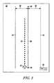
- FIGs. 2 and 3 illustrate a navigational map display having first and second fields of view, respectively, that may be generated by the display system shown in FIG. 1 ;
- FIG. 4 is a flowchart illustrating an exemplary process that may be carried out by the display system of FIG. 1 ;
- FIGs. 5 and 6 illustrate the navigational map display shown in FIG. 2 showing first and second alert conditions, respectively.
- FIG. 1 is a functional block diagram of a generalized avionics display system 10 .
- Display system 10 is required navigational performance (RNP) capable. That is, display system is capable of monitoring aircraft position with the degree of accuracy required under RNP protocols established by the Federal Aviation Administration.
- Display system 10 includes at least one monitor 12, a processor 14, and a plurality of data sources 16.
- display system 10 may also include a user input 18, such as a keyboard and/or a cursor control device (e.g., a trackball).
- Processor 14 includes at least first and second inputs, which are operatively coupled to data sources 16 and input device 18, respectively.
- Processor 14 further includes at least one output, which is operatively coupled to monitor 12.
- Monitor 12 may comprise any suitable image-generating device including various analog devices (e.g., cathode ray tube) and digital devices (e.g., liquid crystal, active matrix, plasma, etc.). In one option, monitor 12 is a head-up display.
- Processor 14 may comprise, or be associated with, any suitable number of individual microprocessors, flight control computers, navigational equipment, memories, power supplies, storage devices, interface cards, and other standard components known in the art. In this respect, the processor 14 may include or cooperate with any number of software programs (e.g., avionics display programs) or instructions designed to carry out the various methods, process tasks, calculations, and control/display functions described below.
- software programs e.g., avionics display programs
- Data sources 16 provide static and/or real-time information to processor 14, which processor 14 utilizes to generate one or more displays on monitor 12, such as a navigational map display.
- Data sources 16 may include a wide variety of informational systems, which may reside onboard the aircraft or at a remote location.
- data sources 16 may include one or more of the following systems: a runaway awareness and advisory system, an instrument landing system, a flight director system, a weather data system, a terrain avoidance and warning system, a traffic and collision avoidance system, a terrain database, an initial reference system, and a navigational database.
- Data sources 16 may also include mode, position, and/or detection elements (e.g., gyroscopes, global positioning systems, inertial reference systems, etc.) capable of determining the mode and/or position of the aircraft relative to one or more reference locations, points, planes, or navigation aids.
- mode, position, and/or detection elements e.g., gyroscopes, global positioning systems, inertial reference systems, etc.
- FIG. 2 illustrates an exemplary navigational map display 20 that processor 14 may produce on monitor 12.
- Map display 20 provides a two dimensional, top down view of the aircraft's position, projected flight path, flight plan, and surrounding environment.
- an aircraft symbol 22 may be utilized to denote the aircraft's position
- a dotted line 24 may be utilized to denote the aircraft's projected flight path
- a solid line 26 connecting way point symbols 28 may be utilized to denote a leg segment of the aircraft's flight plan.
- solid line 26 represents a landing leg, which terminates at a designated runway as indicated by runway graphic 30.
- Various other symbols may also be displayed on navigational map display 20 in addition to those shown in FIG. 2 , including, for example, symbols denoting terrain (e.g., mountains), weather, political boundaries, and other information useful in the piloting of an aircraft.
- a particular RNP value may be assigned to the leg of the aircraft's flight plan shown in FIG. 2 .
- this RNP value (e.g., 2.0 nautical miles) may be graphically indicated on map display 20; e.g., expressed within a text box 32.
- the RNP value defines an airspace commonly referred to as the RNP corridor.
- Processor 14 is configured to produce at least one graphic on navigational map display 20 indicative of the lateral boundaries of the RNP corridor.
- the lateral boundaries of the RNP corridor may be represented by first and second dashed lines 34.
- Each dashed line 34 is offset from the projected flight path symbol (solid line 26 ) by a gap 36 having a width corresponding to the current RNP value; e.g., with reference to FIG. 2 , each gap 36 may have a width corresponding to an RNP value of 2.0 nautical miles.
- Navigational map display 20 has a predetermined field of view (FOV), which may be, for example, 20 nautical miles (width) by 30 nautical miles (height).
- FOV field of view
- the FOV of navigational map display 20 is variable and may be adjusted as desired. For example, if more precise maneuvering of the aircraft is required, the FOV of the map display may be decreased to zoom in on the aircraft symbol, the projected flight path symbol, and the leg segment symbol. Conversely, if precise maneuvering is not required, the FOV of the map display may be increased to zoom out and thereby provide the pilot with greater situational awareness of the aircraft's surroundings. As the FOV of map display 20 is adjusted in this manner, the width of each gap 36 will increase or decrease accordingly. This point is further illustrated in FIG.
- map display 20 has a more focused field of view; e.g., 10 nautical miles (width) by 15 nautical miles (height).
- the width of gap 36 has increased in proportion to the decrease in FOV.
- map display 20 provides the pilot with a more detailed view of the aircraft's flight plan (solid line 26 ) and projected flight path (dotted line 24 ) with respect to the RNP corridor boundaries (dashed lines 34 ).
- the offset or separation between corridor boundary graphics (dashed lines 34) and the projected flight path symbol (solid line 26 ) corresponds to the RNP value scaled to the FOV of navigational map display 20.
- processor 14 will alter offset between the leg segment symbol (solid line 26 ) and the corridor boundary graphics (dashed lines 34) accordingly.
- processor 14 will adjust the offset between the leg segment symbol (solid line 26 ) and the corridor boundary graphics (dashed lines 34 ) to correspond to the new RNP value.
- FIG. 4 is a flowchart illustrating an exemplary process that may be carried out by processor 14 in generating a graphic indicative of the lateral boundaries of the RNP corridor on navigational map display 20.
- processor 14 may also be configured to generate an alert signal if an alert condition is detected. For example, processor 14 may generate an alert signal if either: (1) the aircraft's current position resides outside of the RNP corridor, or (2) the aircraft's projected flight path is projected to breach an RNP corridor boundary.
- the alert signal may comprise a visual, audible, and/or haptic alarm of any suitable type; however, the alert signal preferably comprises a visual change to map display 20 (e.g., an alteration in color of one or more graphics displayed on display 20 ) so as to provide the crew members with an intuitive head-up alert of the condition.
- map display 20 e.g., an alteration in color of one or more graphics displayed on display 20
- the exemplary process of FIG. 4 commences as processor 14 establishes the RNP value associated with the current leg of the flight plan (STEP 38 ).
- the RNP value may be supplied by a crew member (e.g., the pilot) utilizing input device 18 ( FIG. 1 ). Alternatively, the RNP value may be recalled from a memory associated with processor 14 or wirelessly communicated to processor 14 by the air traffic controller.
- Processor 14 then scales the RNP value to the current FOV of navigational map display 20 (STEP 40 ), and generates RNP corridor boundary graphics (e.g., dashed lines 34 ) on display 20 (STEP 42 ).
- the RNP corridor boundary graphics are offset from the aircraft leg segment symbol (e.g., solid line 26 ) by the scaled RNP value as explained above in conjunction with FIGs. 2 and 3 .
- processor 14 After generating the RNP corridor boundary graphics on map display 20, processor 14 next determines whether an alert condition is detected and, consequently, whether an alert signal should be generated. To this end, processor 14 may first estimate the current position of the aircraft (STEP 44 ). Processor 14 compares the estimated position of the aircraft to the location of the RNP corridor boundaries to determine whether the aircraft's position resides outside of the corridor (STEP 46 ). If determining that the aircraft's estimated position is within the corridor, processor 14 advances to STEP 48 described below. If processor 14 instead determines that the aircraft's estimated position falls outside of the corridor, processor may generate a first alert signal (STEP 50 ).
- this alert may take any suitable form (e.g., activation of a cabin alert light or of a warning indicator light disposed on the master control display unit), the alert preferably comprises a readily-appreciable change in the color of one or more of the graphics displayed on map display 20; e.g., the RNP corridor boundary graphics (dashed lines 34 ) and/or the leg segment symbol (solid line 26 ) may change from a first color (e.g., green) to a second color (e.g., red).
- a first color e.g., green
- a second color e.g., red
- FIG. 5 An example of a condition under which processor 14 would generate such an alert is illustrated in FIG. 5 . After generating the first alert, processor 14 continues onward to STEP 48.
- processor 14 projects the aircraft flight path utilizing operational parameters (e.g., aircraft speed, bank angle, wind sheer, etc.) supplied by data sources 16 ( FIG. 1 ) in the well-known manner.
- Processor 14 compares the projected flight path to the RNP corridor (STEP 52 ) to determine whether the flight path breaches, or crosses over, an RNP corridor boundary. If the projected flight path does not breach an RNP corridor boundary, processor 14 returns to STEP 38 and the process repeats. If, however, processor 14 determines that the projected flight path does breach an RNP corridor boundary, processor 14 generates a second alert signal (STEP 54 ), which may be similar or identical to the first alert signal.
- operational parameters e.g., aircraft speed, bank angle, wind sheer, etc.
- the second alert signal may again comprise a color change of one or more graphics displayed on map display 20; e.g., the RNP corridor boundary graphics (dashed lines 34 ) and/or the leg segment symbol (solid line 26 ) may change from the first color (e.g., green) to a third color (e.g., orange).
- a condition under which processor 14 would generate the second alert is illustrated in FIG. 6 . After generating the second alert, processor 14 returns to STEP 38 and the process repeats.
- an aircraft display system and method for displaying RNP corridor boundaries on a navigational map display in an intuitive manner.
- the above-described aircraft display system and method permits the RNP corridor to be scalable to the field of view of the map display to thereby permit the pilot (or other crew member) to view the aircraft flight plan, projected flight path, and RNP corridor in a desired level of detail.
- the aircraft display system and method may also be configured to generate an alert if the aircraft is currently outside of the RNP corridor or is projected to breach an RNP corridor boundary. While an exemplary embodiment of the present invention has been described above in the context of a fully functioning computer system (i.e., avionics display system 10 shown in FIG.
Description
- The present invention relates generally to vehicular display systems, and, more particularly, to an aircraft display system and method for indicating the boundaries of a required navigational performance corridor on an aircraft's navigational map display.
- The Federal Aviation Administration has developed required navigation performance (RNP) protocols to facilitate the management of air traffic. Under these protocols, RNP values (e.g., 0.1 to 30 nautical miles) may be assigned to various particular segments, or legs, of an aircraft's flight plan. For example, when an aircraft approaches an airfield, the aircraft may be assigned a particular flight plan segment, or landing leg, by the air traffic controller. Depending upon air traffic, the air traffic controller may also communicate to the aircraft's crew (e.g., pilot) an RNP value associated with the landing leg (e.g., 2.0 nautical miles). The RNP value defines an airspace within which the aircraft should remain for a predetermined percentage (e.g., 95 percent) of the total flying time. This airspace may be referred to as the RNP Obstacle Evaluation Area or, more simply, the RNP corridor. If the aircraft is RNP capable and if the pilot is appropriately certified, the pilot may attempt to travel the assigned landing leg while remaining within the RNP corridor. If, during the landing attempt, the aircraft breaches an RNP boundary and leaves the corridor, a warning indicator (e.g., a hazard light) is produced inside the aircraft's cabin and the landing may be aborted and attempted again at a later time.
- Many conventional aircraft display systems do not provide a visual indication of the location of the RNP corridor boundaries relative to the aircraft's position and projected flight path. Such conventional aircraft display systems do not graphically indicate whether, under the current flight parameters (e.g., aircraft speed, bank angle, pitch, yaw, wind sheer, etc.), the aircraft will travel outside of the RNP corridor. Consequently, the flight crew may need to interpret data from various aircraft systems to estimate the location of the RNP corridor boundaries. This can increase the flight crew's overall workload. In addition, this may deter the pilot from taking corrective actions to maintain the aircraft within the RNP corridor. As a result, the likelihood of an RNP corridor containment breach and, thus, an aborted landing, is increased.
-
EP 1 273 987 - It is thus desirable to provide an aircraft display system and method for graphically indicating the boundaries of an RNP corridor on a display (e.g., a navigational map display) in an intuitive manner. In addition, it would be desirable for the RNP corridor to be scalable to the field of view of the map display to thereby permit the pilot (or other crew member) to view the aircraft flight plan and projected flight path relative to the RNP corridor in a desired level of detail. Finally, it would be desirable if the aircraft display system were configured to generate an alert if the aircraft is currently outside of the RNP corridor or is projected to breach an RNP corridor boundary. Other desirable features and characteristics of the present invention will become apparent from the subsequent detailed description of the invention and the appended claims, taken in conjunction with the accompanying drawings and this background of the invention.
- The present invention in its various aspects is as set out in the appended claims. A method is provided for indicating the boundaries of a required navigational performance (RNP) corridor on an aircraft's map display. The method includes the steps of producing an aircraft leg segment symbol on the map display, establishing an RNP value, and scaling the RNP value to the map display field of view. The method further includes the step of generating an RNP corridor boundary graphic on the map display offset from the aircraft leg segment symbol by the scaled RNP value.
- A program product is also provided that includes an avionics display program and computer-readable media bearing the avionics display program. The avionics display program is adapted to generate a map display having a field of view (FOV) and including a leg segment symbol. The display program establishes an RNP value, scales the RNP value to the map display FOV, and produces an RNP corridor boundary graphic on the map display separated from the leg segment symbol the scaled RNP value.
- Lastly, an aircraft display system is provided, which includes a monitor, at least one data source, and a processor coupled to the monitor and the at least one data source. The processor is configured to generate on the monitor a map display including a leg segment symbol and RNP corridor boundary graphics. The RNP corridor boundary graphics are separated from the leg segment symbol by a gap corresponding to the RNP value scaled to map display field of view.
- The present invention will hereinafter be described in conjunction with the following drawing figures, wherein like numerals denote like elements, and:
-
FIG. 1 is a block diagram of a generalized avionics display system in accordance with a first exemplary embodiment of the present invention; -
FIGs. 2 and3 illustrate a navigational map display having first and second fields of view, respectively, that may be generated by the display system shown inFIG. 1 ; -
FIG. 4 is a flowchart illustrating an exemplary process that may be carried out by the display system ofFIG. 1 ; and -
FIGs. 5 and6 illustrate the navigational map display shown inFIG. 2 showing first and second alert conditions, respectively. - The following detailed description of the invention is merely exemplary in nature and is not intended to limit the invention or the application and uses of the invention. Furthermore, there is no intention to be bound by any theory presented in the preceding background of the invention or the following detailed description of the invention.
-
FIG. 1 is a functional block diagram of a generalizedavionics display system 10.Display system 10 is required navigational performance (RNP) capable. That is, display system is capable of monitoring aircraft position with the degree of accuracy required under RNP protocols established by the Federal Aviation Administration.Display system 10 includes at least onemonitor 12, aprocessor 14, and a plurality ofdata sources 16. In certain embodiments,display system 10 may also include auser input 18, such as a keyboard and/or a cursor control device (e.g., a trackball).Processor 14 includes at least first and second inputs, which are operatively coupled todata sources 16 andinput device 18, respectively.Processor 14 further includes at least one output, which is operatively coupled to monitor 12.Monitor 12 may comprise any suitable image-generating device including various analog devices (e.g., cathode ray tube) and digital devices (e.g., liquid crystal, active matrix, plasma, etc.). In one option,monitor 12 is a head-up display.Processor 14 may comprise, or be associated with, any suitable number of individual microprocessors, flight control computers, navigational equipment, memories, power supplies, storage devices, interface cards, and other standard components known in the art. In this respect, theprocessor 14 may include or cooperate with any number of software programs (e.g., avionics display programs) or instructions designed to carry out the various methods, process tasks, calculations, and control/display functions described below. -
Data sources 16 provide static and/or real-time information toprocessor 14, whichprocessor 14 utilizes to generate one or more displays onmonitor 12, such as a navigational map display.Data sources 16 may include a wide variety of informational systems, which may reside onboard the aircraft or at a remote location. By way of example,data sources 16 may include one or more of the following systems: a runaway awareness and advisory system, an instrument landing system, a flight director system, a weather data system, a terrain avoidance and warning system, a traffic and collision avoidance system, a terrain database, an initial reference system, and a navigational database.Data sources 16 may also include mode, position, and/or detection elements (e.g., gyroscopes, global positioning systems, inertial reference systems, etc.) capable of determining the mode and/or position of the aircraft relative to one or more reference locations, points, planes, or navigation aids. -
FIG. 2 illustrates an exemplarynavigational map display 20 thatprocessor 14 may produce onmonitor 12.Map display 20 provides a two dimensional, top down view of the aircraft's position, projected flight path, flight plan, and surrounding environment. Although the particular symbology may vary from system to system, anaircraft symbol 22 may be utilized to denote the aircraft's position, adotted line 24 may be utilized to denote the aircraft's projected flight path, and asolid line 26 connectingway point symbols 28 may be utilized to denote a leg segment of the aircraft's flight plan. In the illustrated exemplary embodiment,solid line 26 represents a landing leg, which terminates at a designated runway as indicated byrunway graphic 30. Various other symbols may also be displayed onnavigational map display 20 in addition to those shown inFIG. 2 , including, for example, symbols denoting terrain (e.g., mountains), weather, political boundaries, and other information useful in the piloting of an aircraft. - A particular RNP value, typically ranging from 0.1 to 30 nautical miles, may be assigned to the leg of the aircraft's flight plan shown in
FIG. 2 . For the pilot's reference, this RNP value (e.g., 2.0 nautical miles) may be graphically indicated onmap display 20; e.g., expressed within atext box 32. As explained above, the RNP value defines an airspace commonly referred to as the RNP corridor.Processor 14 is configured to produce at least one graphic onnavigational map display 20 indicative of the lateral boundaries of the RNP corridor. For example, the lateral boundaries of the RNP corridor may be represented by first and second dashedlines 34. Each dashedline 34 is offset from the projected flight path symbol (solid line 26) by agap 36 having a width corresponding to the current RNP value; e.g., with reference toFIG. 2 , eachgap 36 may have a width corresponding to an RNP value of 2.0 nautical miles. -
Navigational map display 20 has a predetermined field of view (FOV), which may be, for example, 20 nautical miles (width) by 30 nautical miles (height). The FOV ofnavigational map display 20 is variable and may be adjusted as desired. For example, if more precise maneuvering of the aircraft is required, the FOV of the map display may be decreased to zoom in on the aircraft symbol, the projected flight path symbol, and the leg segment symbol. Conversely, if precise maneuvering is not required, the FOV of the map display may be increased to zoom out and thereby provide the pilot with greater situational awareness of the aircraft's surroundings. As the FOV ofmap display 20 is adjusted in this manner, the width of eachgap 36 will increase or decrease accordingly. This point is further illustrated inFIG. 3 , which showsmap display 20 having a more focused field of view; e.g., 10 nautical miles (width) by 15 nautical miles (height). As can be seen, the width ofgap 36 has increased in proportion to the decrease in FOV. As a result,map display 20 provides the pilot with a more detailed view of the aircraft's flight plan (solid line 26) and projected flight path (dotted line 24) with respect to the RNP corridor boundaries (dashed lines 34). - In view of the foregoing description, it should be appreciated that the offset or separation between corridor boundary graphics (dashed lines 34) and the projected flight path symbol (solid line 26) corresponds to the RNP value scaled to the FOV of
navigational map display 20. Thus, as the FOV ofmap display 20 changes,processor 14 will alter offset between the leg segment symbol (solid line 26) and the corridor boundary graphics (dashed lines 34) accordingly. Similarly, if the RNP value is changed (e.g., if the pilot enters a new RNP value utilizing input device 18),processor 14 will adjust the offset between the leg segment symbol (solid line 26) and the corridor boundary graphics (dashed lines 34) to correspond to the new RNP value. -
FIG. 4 is a flowchart illustrating an exemplary process that may be carried out byprocessor 14 in generating a graphic indicative of the lateral boundaries of the RNP corridor onnavigational map display 20. By executing the exemplary process shown inFIG. 4 ,processor 14 may also be configured to generate an alert signal if an alert condition is detected. For example,processor 14 may generate an alert signal if either: (1) the aircraft's current position resides outside of the RNP corridor, or (2) the aircraft's projected flight path is projected to breach an RNP corridor boundary. The alert signal may comprise a visual, audible, and/or haptic alarm of any suitable type; however, the alert signal preferably comprises a visual change to map display 20 (e.g., an alteration in color of one or more graphics displayed on display 20) so as to provide the crew members with an intuitive head-up alert of the condition. - The exemplary process of
FIG. 4 commences asprocessor 14 establishes the RNP value associated with the current leg of the flight plan (STEP 38). The RNP value may be supplied by a crew member (e.g., the pilot) utilizing input device 18 (FIG. 1 ). Alternatively, the RNP value may be recalled from a memory associated withprocessor 14 or wirelessly communicated toprocessor 14 by the air traffic controller.Processor 14 then scales the RNP value to the current FOV of navigational map display 20 (STEP 40), and generates RNP corridor boundary graphics (e.g., dashed lines 34) on display 20 (STEP 42). The RNP corridor boundary graphics are offset from the aircraft leg segment symbol (e.g., solid line 26) by the scaled RNP value as explained above in conjunction withFIGs. 2 and3 . - After generating the RNP corridor boundary graphics on
map display 20,processor 14 next determines whether an alert condition is detected and, consequently, whether an alert signal should be generated. To this end,processor 14 may first estimate the current position of the aircraft (STEP 44).Processor 14 compares the estimated position of the aircraft to the location of the RNP corridor boundaries to determine whether the aircraft's position resides outside of the corridor (STEP 46). If determining that the aircraft's estimated position is within the corridor,processor 14 advances to STEP 48 described below. Ifprocessor 14 instead determines that the aircraft's estimated position falls outside of the corridor, processor may generate a first alert signal (STEP 50). Although this alert may take any suitable form (e.g., activation of a cabin alert light or of a warning indicator light disposed on the master control display unit), the alert preferably comprises a readily-appreciable change in the color of one or more of the graphics displayed onmap display 20; e.g., the RNP corridor boundary graphics (dashed lines 34) and/or the leg segment symbol (solid line 26) may change from a first color (e.g., green) to a second color (e.g., red). An example of a condition under whichprocessor 14 would generate such an alert is illustrated inFIG. 5 . After generating the first alert,processor 14 continues onward toSTEP 48. - At
STEP 48,processor 14 projects the aircraft flight path utilizing operational parameters (e.g., aircraft speed, bank angle, wind sheer, etc.) supplied by data sources 16 (FIG. 1 ) in the well-known manner.Processor 14 then compares the projected flight path to the RNP corridor (STEP 52) to determine whether the flight path breaches, or crosses over, an RNP corridor boundary. If the projected flight path does not breach an RNP corridor boundary,processor 14 returns to STEP 38 and the process repeats. If, however,processor 14 determines that the projected flight path does breach an RNP corridor boundary,processor 14 generates a second alert signal (STEP 54), which may be similar or identical to the first alert signal. For example, the second alert signal may again comprise a color change of one or more graphics displayed onmap display 20; e.g., the RNP corridor boundary graphics (dashed lines 34) and/or the leg segment symbol (solid line 26) may change from the first color (e.g., green) to a third color (e.g., orange). An example of a condition under whichprocessor 14 would generate the second alert is illustrated inFIG. 6 . After generating the second alert,processor 14 returns to STEP 38 and the process repeats. - It should thus be appreciated that there has been provided an aircraft display system and method for displaying RNP corridor boundaries on a navigational map display in an intuitive manner. The above-described aircraft display system and method permits the RNP corridor to be scalable to the field of view of the map display to thereby permit the pilot (or other crew member) to view the aircraft flight plan, projected flight path, and RNP corridor in a desired level of detail. In addition, the aircraft display system and method may also be configured to generate an alert if the aircraft is currently outside of the RNP corridor or is projected to breach an RNP corridor boundary. While an exemplary embodiment of the present invention has been described above in the context of a fully functioning computer system (i.e.,
avionics display system 10 shown inFIG. 1 ), those skilled in the art will recognize that the mechanisms of the present invention are capable of being distributed as a program product (i.e., an avionics display program) and, furthermore, that the teachings of the present invention apply to the program product regardless of the particular type of computer-readable media (e.g., floppy disc, hard drive, memory card, optical disc, etc.) employed to carry-out its distribution. - While at least one exemplary embodiment has been presented in the foregoing detailed description of the invention, it should be appreciated that a vast number of variations exist. It should also be appreciated that the exemplary embodiment or exemplary embodiments are only examples, and are not intended to limit the scope, applicability, or configuration of the invention in any way. Rather, the foregoing detailed description will provide those skilled in the art with a convenient road map for implementing an exemplary embodiment of the invention. It being understood that various changes may be made in the function and arrangement of elements described in an exemplary embodiment without departing from the scope of the invention as set forth in the appended claims.
Claims (10)
- A method for indicating the boundaries of a required navigational performance (RNP) corridor on an aircraft's top-down map display (20), the method comprising:producing an aircraft leg segment symbol (26) on the top-down map display;establishing an RNP value (36); andgenerating an RNP corridor boundary graphic on the top-down map display offset from the aircraft leg segment symbol by the RNP value;the method being characterized in that the RNP value is scaled to the map display field of view (FOV), in that the RNP corridor boundary graphic comprises at least one line (34), in that the map display FOV is selectively changeable, and in that the offset between the aircraft leg segment symbol and the RNP corridor boundary graphic is adjusted in accordance with change in map display FOV.
- A method according to Claim 1 further comprising:estimating the aircraft's position (44); andgenerating an alert signal if the aircraft's estimated position is outside of the RNP corridor (46, 50).
- A method according to Claim 2 wherein the step of generating an alert signal (46, 50) comprises producing a visual alert on the map display (20).
- A method according to Claim 3 wherein the step of producing a visual alert comprises alerting the color of the RNP corridor boundary graphic (34).
- A method according to Claim 1 further comprising;
projecting the aircraft's flight path (48); and
generating an alert signal if the aircraft's projected flight path breaches an RNP corridor boundary (52, 54). - A method according to Claim 5 wherein the step of generating an alert signal (52, 54) comprises producing a visual alert on the map display (20).
- A method according to Claim 6 wherein the step of producing a visual alert on the map display (20) comprises alerting the color of the RNP corridor boundary graphic (34).
- A method according to Claim 1 further comprising adjusting the offset between the aircraft leg segment symbol (26) and the RNP corridor boundary graphic (34) in accordance with change in RNP value.
- A program product, comprising:an avionics display program adapted to:generate a top-down map display (20) having a field of view (FOV) and including an aircraft leg segment symbol (26);establish an RNP value (36); andproduce an RNP corridor boundary graphic on the top-down map display offset from the aircraft leg segment symbol by the RNP value; andcomputer-readable media bearing the avionics display program;the program product being characterized in that the RNP value is scaled to the map display FOV, in that the RNP corridor boundary graphic comprises at least one line (34), in that the map display FOV is selectively changeable, and in that the offset between the aircraft leg segment symbol and the RNP corridor boundary graphic is adjusted in accordance with change in map display FOV.
- An aircraft display system (10), comprising:a monitor (12);at least one data source (16); anda processor (14) coupled to the monitor and the at least one data source, the processor configured to generate on the monitor a top down map display (20) including an aircraft leg segment symbol (26) and an RNP corridor boundary graphic, the RNP corridor boundary graphic offset from the aircraft leg segment symbol by a gap corresponding to an established RNP value (36);the aircraft display system being characterized in that the RNP value is scaled to the map display FOV, in that the RNP corridor boundary graphic comprises at least one line (34), in that the map display FOV is selectively changeable, and in that the offset between the aircraft leg segment symbol and the RNP corridor boundary graphic is adjusted in accordance with change in map display FOV.
Applications Claiming Priority (1)
| Application Number | Priority Date | Filing Date | Title |
|---|---|---|---|
| US11/764,510 US7830276B2 (en) | 2007-06-18 | 2007-06-18 | System and method for displaying required navigational performance corridor on aircraft map display |
Publications (3)
| Publication Number | Publication Date |
|---|---|
| EP2009612A2 EP2009612A2 (en) | 2008-12-31 |
| EP2009612A3 EP2009612A3 (en) | 2010-05-26 |
| EP2009612B1 true EP2009612B1 (en) | 2011-04-13 |
Family
ID=39737013
Family Applications (1)
| Application Number | Title | Priority Date | Filing Date |
|---|---|---|---|
| EP08158286A Active EP2009612B1 (en) | 2007-06-18 | 2008-06-13 | System and method for displaying required navigational performance corridor on aircraft map display |
Country Status (3)
| Country | Link |
|---|---|
| US (1) | US7830276B2 (en) |
| EP (1) | EP2009612B1 (en) |
| DE (1) | DE602008006129D1 (en) |
Cited By (1)
| Publication number | Priority date | Publication date | Assignee | Title |
|---|---|---|---|---|
| EP3258457B1 (en) * | 2016-06-13 | 2024-04-03 | Honeywell International Inc. | Systems and methods for situational awareness of current and future vehicle state |
Families Citing this family (21)
| Publication number | Priority date | Publication date | Assignee | Title |
|---|---|---|---|---|
| JP4760831B2 (en) * | 2005-08-02 | 2011-08-31 | 日産自動車株式会社 | Vehicle perimeter monitoring apparatus and vehicle perimeter monitoring method |
| US20090128630A1 (en) * | 2006-07-06 | 2009-05-21 | Nissan Motor Co., Ltd. | Vehicle image display system and image display method |
| US7945356B2 (en) * | 2007-06-29 | 2011-05-17 | The Boeing Company | Portable autonomous terminal guidance system |
| US8718931B2 (en) * | 2007-10-31 | 2014-05-06 | The Boeing Company | Method and apparatus for cross checking required navigation performance procedures |
| US8576094B2 (en) * | 2008-08-29 | 2013-11-05 | Honeywell International Inc. | Method and system for displaying navigation corridors |
| US20100152932A1 (en) * | 2008-12-17 | 2010-06-17 | Honeywell International Inc. | System and method for rendering aircraft traffic on a vertical situation display |
| US9330573B2 (en) | 2009-06-25 | 2016-05-03 | Honeywell International Inc. | Automated decision aid tool for prompting a pilot to request a flight level change |
| US8271152B2 (en) * | 2010-03-10 | 2012-09-18 | Honeywell International Inc. | System and method for rendering an onboard aircraft display for use with in-trail procedures |
| US8417397B2 (en) | 2010-05-05 | 2013-04-09 | Honeywell International Inc. | Vertical profile display with variable display boundaries |
| US8478513B1 (en) | 2012-01-20 | 2013-07-02 | Honeywell International Inc. | System and method for displaying degraded traffic data on an in-trail procedure (ITP) display |
| US8554394B2 (en) | 2012-02-28 | 2013-10-08 | Honeywell International Inc. | System and method for rendering an aircraft cockpit display for use with an in-trail procedure (ITP) |
| FR2988201B1 (en) | 2012-03-13 | 2014-05-02 | Thales Sa | METHOD FOR AIDING ANTICIPATION NAVIGATION OF LINEAR OR ANGULAR DEVIATIONS |
| US8781649B2 (en) | 2012-03-19 | 2014-07-15 | Honeywell International Inc. | System and method for displaying in-trail procedure (ITP) opportunities on an aircraft cockpit display |
| FR2998065B1 (en) | 2012-11-09 | 2016-12-09 | Thales Sa | SYSTEM FOR ANTICIPATING THE NAVIGATION ACCURACIES REQUIRED |
| US9734161B2 (en) * | 2013-03-15 | 2017-08-15 | The Florida International University Board Of Trustees | Streaming representation of moving objects and shapes in a geographic information service |
| US9697737B2 (en) | 2014-09-30 | 2017-07-04 | The Boeing Company | Automatic real-time flight plan updates |
| US9530320B2 (en) | 2014-09-30 | 2016-12-27 | The Boeing Company | Flight object communications system |
| US9424755B2 (en) | 2014-09-30 | 2016-08-23 | The Boeing Company | Flight analogous and projection system |
| US10121384B2 (en) * | 2014-09-30 | 2018-11-06 | The Boeing Company | Aircraft performance predictions |
| US9443434B2 (en) | 2014-09-30 | 2016-09-13 | The Boeing Company | Flight path discontinuities |
| CN113815874B (en) * | 2021-10-11 | 2022-06-21 | 中国商用飞机有限责任公司 | Alarm information pushing method and system for aircraft |
Family Cites Families (12)
| Publication number | Priority date | Publication date | Assignee | Title |
|---|---|---|---|---|
| FR2666428B1 (en) * | 1990-09-05 | 1994-09-23 | Aerospatiale | METHOD OF VIEWING ON A SCREEN ON BOARD AN AIRPLANE, SYMBOLS FOR PILOTAGE. |
| DE4314811A1 (en) * | 1993-05-05 | 1994-12-08 | Vdo Luftfahrtgeraete Werk Gmbh | Procedure for displaying flight guidance information |
| US6995690B1 (en) * | 1999-07-30 | 2006-02-07 | The Boeing Company | Vertical situation display terrain/waypoint swath, range to target speed, and blended airplane reference |
| US6571155B2 (en) * | 2001-07-02 | 2003-05-27 | The Boeing Company | Assembly, computer program product and method for displaying navigation performance based flight path deviation information |
| US6812858B2 (en) * | 2001-08-20 | 2004-11-02 | The Boeing Company | Integrated display for aircrafts |
| US6798423B2 (en) * | 2001-10-11 | 2004-09-28 | The Boeing Company | Precision perspective flight guidance symbology system |
| US6885313B2 (en) * | 2003-03-26 | 2005-04-26 | Honeywell International Inc. | Graphical display for aircraft navigation |
| EP1687590B1 (en) * | 2003-11-25 | 2013-11-27 | Honeywell International Inc. | Perspective vertical situation display system and method |
| US7256710B2 (en) * | 2004-06-30 | 2007-08-14 | The Boeing Company | Methods and systems for graphically displaying sources for and natures of aircraft flight control instructions |
| US7650232B1 (en) * | 2005-09-22 | 2010-01-19 | The United States Of America As Represented By The Administrator Of The National Aeronautics And Space Administration (Nasa) | Trajectory specification for high capacity air traffic control |
| FR2897712B1 (en) * | 2006-02-20 | 2008-04-04 | Airbus France Sas | DEVICE FOR AIDING THE CONTROL OF AN AIRCRAFT DURING AN APPROACH PHASE FOR LANDING. |
| US8027756B2 (en) * | 2006-12-07 | 2011-09-27 | The Boeing Company | Integrated approach navigation system, method, and computer program product |
-
2007
- 2007-06-18 US US11/764,510 patent/US7830276B2/en active Active
-
2008
- 2008-06-13 DE DE602008006129T patent/DE602008006129D1/en active Active
- 2008-06-13 EP EP08158286A patent/EP2009612B1/en active Active
Cited By (1)
| Publication number | Priority date | Publication date | Assignee | Title |
|---|---|---|---|---|
| EP3258457B1 (en) * | 2016-06-13 | 2024-04-03 | Honeywell International Inc. | Systems and methods for situational awareness of current and future vehicle state |
Also Published As
| Publication number | Publication date |
|---|---|
| EP2009612A2 (en) | 2008-12-31 |
| EP2009612A3 (en) | 2010-05-26 |
| DE602008006129D1 (en) | 2011-05-26 |
| US7830276B2 (en) | 2010-11-09 |
| US20080309518A1 (en) | 2008-12-18 |
Similar Documents
| Publication | Publication Date | Title |
|---|---|---|
| EP2009612B1 (en) | System and method for displaying required navigational performance corridor on aircraft map display | |
| US8378852B2 (en) | Aircraft-centered ground maneuvering monitoring and alerting system | |
| US8676399B2 (en) | System and method for generating and displaying an electric taxi index | |
| CN105549938B (en) | System and method for displaying runway landing information | |
| US8373579B2 (en) | Aircraft ground maneuvering monitoring system | |
| US9499279B2 (en) | System and method for displaying runway approach information | |
| US10214300B2 (en) | System and method for displaying runway overrun information | |
| US9501936B2 (en) | Aircraft systems and methods for displaying spacing information | |
| US8604942B2 (en) | System and method for displaying a velocity rate-of-change indicator | |
| EP2194361B1 (en) | System for enhancing obstacles and terrain profile awareness | |
| EP2871549A2 (en) | System and method for alerting of remaining runway upon landing based on deceleration | |
| CN105651305B (en) | System and method for outward display of integrated navigation | |
| EP1972897B1 (en) | System and method for indicating the field of view of a three dimensional display on a two dimensional display | |
| EP2913813B1 (en) | System and method for runway selection through scoring | |
| EP2175242B1 (en) | System for displaying required navigation performance on a horizontal situation indicator | |
| US8155800B2 (en) | System for displaying required navigation performance on a horizontal situation indicator | |
| EP2801964A1 (en) | System and method for displaying rate-of-climb on an avionics vertical speed indicator |
Legal Events
| Date | Code | Title | Description |
|---|---|---|---|
| PUAI | Public reference made under article 153(3) epc to a published international application that has entered the european phase |
Free format text: ORIGINAL CODE: 0009012 |
|
| 17P | Request for examination filed |
Effective date: 20080613 |
|
| AK | Designated contracting states |
Kind code of ref document: A2 Designated state(s): AT BE BG CH CY CZ DE DK EE ES FI FR GB GR HR HU IE IS IT LI LT LU LV MC MT NL NO PL PT RO SE SI SK TR |
|
| AX | Request for extension of the european patent |
Extension state: AL BA MK RS |
|
| PUAL | Search report despatched |
Free format text: ORIGINAL CODE: 0009013 |
|
| AK | Designated contracting states |
Kind code of ref document: A3 Designated state(s): AT BE BG CH CY CZ DE DK EE ES FI FR GB GR HR HU IE IS IT LI LT LU LV MC MT NL NO PL PT RO SE SI SK TR |
|
| AX | Request for extension of the european patent |
Extension state: AL BA MK RS |
|
| 17Q | First examination report despatched |
Effective date: 20100518 |
|
| GRAP | Despatch of communication of intention to grant a patent |
Free format text: ORIGINAL CODE: EPIDOSNIGR1 |
|
| RIC1 | Information provided on ipc code assigned before grant |
Ipc: G08G 5/00 20060101AFI20101209BHEP Ipc: G01C 23/00 20060101ALI20101209BHEP |
|
| AKX | Designation fees paid |
Designated state(s): DE FR GB |
|
| GRAS | Grant fee paid |
Free format text: ORIGINAL CODE: EPIDOSNIGR3 |
|
| GRAA | (expected) grant |
Free format text: ORIGINAL CODE: 0009210 |
|
| AK | Designated contracting states |
Kind code of ref document: B1 Designated state(s): DE FR GB |
|
| REG | Reference to a national code |
Ref country code: GB Ref legal event code: FG4D |
|
| REF | Corresponds to: |
Ref document number: 602008006129 Country of ref document: DE Date of ref document: 20110526 Kind code of ref document: P |
|
| REG | Reference to a national code |
Ref country code: DE Ref legal event code: R096 Ref document number: 602008006129 Country of ref document: DE Effective date: 20110526 |
|
| PLBE | No opposition filed within time limit |
Free format text: ORIGINAL CODE: 0009261 |
|
| STAA | Information on the status of an ep patent application or granted ep patent |
Free format text: STATUS: NO OPPOSITION FILED WITHIN TIME LIMIT |
|
| 26N | No opposition filed |
Effective date: 20120116 |
|
| REG | Reference to a national code |
Ref country code: DE Ref legal event code: R097 Ref document number: 602008006129 Country of ref document: DE Effective date: 20120116 |
|
| REG | Reference to a national code |
Ref country code: FR Ref legal event code: PLFP Year of fee payment: 9 |
|
| REG | Reference to a national code |
Ref country code: FR Ref legal event code: PLFP Year of fee payment: 10 |
|
| REG | Reference to a national code |
Ref country code: FR Ref legal event code: PLFP Year of fee payment: 11 |
|
| PGFP | Annual fee paid to national office [announced via postgrant information from national office to epo] |
Ref country code: GB Payment date: 20220621 Year of fee payment: 15 |
|
| P01 | Opt-out of the competence of the unified patent court (upc) registered |
Effective date: 20230525 |
|
| PGFP | Annual fee paid to national office [announced via postgrant information from national office to epo] |
Ref country code: FR Payment date: 20230622 Year of fee payment: 16 Ref country code: DE Payment date: 20230627 Year of fee payment: 16 |
|
| GBPC | Gb: european patent ceased through non-payment of renewal fee |
Effective date: 20230613 |