EP2014200A2 - Inflatable mattress systems and method of manufacture thereof - Google Patents
Inflatable mattress systems and method of manufacture thereof Download PDFInfo
- Publication number
- EP2014200A2 EP2014200A2 EP08008678A EP08008678A EP2014200A2 EP 2014200 A2 EP2014200 A2 EP 2014200A2 EP 08008678 A EP08008678 A EP 08008678A EP 08008678 A EP08008678 A EP 08008678A EP 2014200 A2 EP2014200 A2 EP 2014200A2
- Authority
- EP
- European Patent Office
- Prior art keywords
- mattress
- air
- tubes
- sheet
- passage
- Prior art date
- Legal status (The legal status is an assumption and is not a legal conclusion. Google has not performed a legal analysis and makes no representation as to the accuracy of the status listed.)
- Granted
Links
Images


Classifications
-
- A—HUMAN NECESSITIES
- A47—FURNITURE; DOMESTIC ARTICLES OR APPLIANCES; COFFEE MILLS; SPICE MILLS; SUCTION CLEANERS IN GENERAL
- A47C—CHAIRS; SOFAS; BEDS
- A47C27/00—Spring, stuffed or fluid mattresses or cushions specially adapted for chairs, beds or sofas
- A47C27/08—Fluid mattresses or cushions
- A47C27/087—Fluid mattresses or cushions with means for connecting opposite sides, e.g. internal ties or strips
-
- A—HUMAN NECESSITIES
- A47—FURNITURE; DOMESTIC ARTICLES OR APPLIANCES; COFFEE MILLS; SPICE MILLS; SUCTION CLEANERS IN GENERAL
- A47C—CHAIRS; SOFAS; BEDS
- A47C27/00—Spring, stuffed or fluid mattresses or cushions specially adapted for chairs, beds or sofas
- A47C27/001—Spring, stuffed or fluid mattresses or cushions specially adapted for chairs, beds or sofas with several cushions, mattresses or the like, to be put together in one cover
-
- A—HUMAN NECESSITIES
- A47—FURNITURE; DOMESTIC ARTICLES OR APPLIANCES; COFFEE MILLS; SPICE MILLS; SUCTION CLEANERS IN GENERAL
- A47C—CHAIRS; SOFAS; BEDS
- A47C27/00—Spring, stuffed or fluid mattresses or cushions specially adapted for chairs, beds or sofas
- A47C27/08—Fluid mattresses or cushions
- A47C27/081—Fluid mattresses or cushions of pneumatic type
-
- A—HUMAN NECESSITIES
- A47—FURNITURE; DOMESTIC ARTICLES OR APPLIANCES; COFFEE MILLS; SPICE MILLS; SUCTION CLEANERS IN GENERAL
- A47C—CHAIRS; SOFAS; BEDS
- A47C27/00—Spring, stuffed or fluid mattresses or cushions specially adapted for chairs, beds or sofas
- A47C27/08—Fluid mattresses or cushions
- A47C27/10—Fluid mattresses or cushions with two or more independently-fillable chambers
-
- A—HUMAN NECESSITIES
- A61—MEDICAL OR VETERINARY SCIENCE; HYGIENE
- A61G—TRANSPORT, PERSONAL CONVEYANCES, OR ACCOMMODATION SPECIALLY ADAPTED FOR PATIENTS OR DISABLED PERSONS; OPERATING TABLES OR CHAIRS; CHAIRS FOR DENTISTRY; FUNERAL DEVICES
- A61G7/00—Beds specially adapted for nursing; Devices for lifting patients or disabled persons
- A61G7/05—Parts, details or accessories of beds
- A61G7/057—Arrangements for preventing bed-sores or for supporting patients with burns, e.g. mattresses specially adapted therefor
- A61G7/05769—Arrangements for preventing bed-sores or for supporting patients with burns, e.g. mattresses specially adapted therefor with inflatable chambers
- A61G7/05776—Arrangements for preventing bed-sores or for supporting patients with burns, e.g. mattresses specially adapted therefor with inflatable chambers with at least two groups of alternately inflated chambers
Abstract
said support tubes being pneumatically enclosed so as to be able to contain air therein at a pressure sufficient to support a person lying on the mattress; and
said support tubes having lateral ends wherein the material of the tubes is gathered together in gussets and the sheets of polymeric material are bonded together, allowing the support tube to inflate to a generally cylindrical shape.
Description
- This invention relates to inflatable devices for supporting a body. The invention is especially applicable in the field of disposable inflatable mattresses, mattress overlays, seat cushions, and back supports, particularly those used for home-care, long-term care and hospital use.
- Inflatable mattresses for people to lie or sleep on are well known in the prior art.
- Generally speaking, such mattresses and cushions, when used for medical applications, are used by immobilized patients. Various types of these mattresses purport to provide a reduced pressure on the body and/or relieve pressure in specific zones or on specific parts of the body. The materials of manufacture of these mattresses generally do not allow water vapor produced by the person's perspiration or condensation to escape from the vicinity of his body, thus requiring an additional item to be placed between the patient and the support surface.
- In addition, inflatable mattresses of the prior art are generally configured so that their construction requires a large amount of labor, usually because the formation of individual air chambers that make up the entire mattress need to be connected in a way that allows the chambers to be filled with air at the time of inflation, and at the same time must be placed and configured to provide suitable support to the user. The prior art designs require a time consuming assembly and mechanical joining of material to make the mattress, and this labor intensive construction of the air mattresses makes the air mattresses expensive, and consequently unsuitable for disposable mattress applications, such as in a hospital environment where the mattress may be contaminated by contact with a patient.
- It is also a problem in the prior art that if there is a rupture or loss of pressure in an inflatable mattress, the entire mattress will collapse. The result may be that, for instance, in a hospital bed, a patient might roll off the underlying bed or mattress system, or be dropped onto an uncomfortable surface below the deflated air mattress.
- It is therefore an object of the present invention to provide an inflatable mattress system which has an outer layer which permits the passage of water vapor but not fluid through it, overlying and working in conjunction with a fill or batting layer which rests on an inflatable mattress underneath. The outer layer is preferably attached to the inflatable mattress as is the fill layer.
- It is also an object of the present invention to provide for an inflatable air mattress of a construction such that it can be readily manufactured without undue amounts of human labor. This is accomplished by providing a mattress construction which allows for continuous formation of the mattresses as a continuous rolled out product so that each individual mattress is formed by cutting the rolled stock, and then finished with a minimum amount of additional sealing. It is also an object of the present invention to provide a method of efficient manufacture of the mattresses from continuously rolled stock.
- It is further an object of the present invention to provide for an inflatable air mattress having two lateral side rail tubes which do not deflate once inflated, even if the central portion of the mattress loses air pressure.
- It is also an object of the present invention to provide an air mattress wherein, even if the central portion below the patient is punctured or loses pressure, a lower set of chambers of the air mattress nonetheless remain inflated and prevent the patient dropping onto the surface of a bed, a bedspring, or another mattress below the air mattress.
- It is also an object of the present invention to provide a mattress having a series of laterally extending support tubes so that adjoining supply tubes can be alternately inflated and deflated, alternatively reducing interface pressure on the body of the user.
- Other benefits and advantages of the present invention will become apparent in the specification hereof, and the scope of the invention will be expressed in the claims.
-
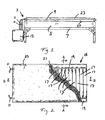
- Figure t shows a elevational view of a inflatable mattress system of the present invention in place on a bed;
-
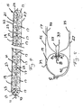
Figure 2 shows a partly cut away plan view of the mattress ofFigure 1 ; -
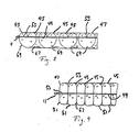
Figure 3 shows a sectional perspective view taken through line A-A ofFigure 2 . -
Figure 4 shows a cross sectional view of the mattress system ofFigure 2 taken through line B-B. -
Figure 5 shows schematically a heat sealing process for the construction of an air mattress of the invention. -
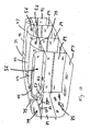
Figure 6 shows a perspective view of an alternate embodiment of a mattress of the invention cutaway along both a longitudinal and lateral plane. -
Figure 7 shows schematically a heat sealing procedure for construction of the air mattress ofFigure 6 . -
Figure 8 is a longitudinal cross sectional view of an alternate embodiment of the mattress shown inFigure 6 . -
Figure 9 is a longitudinal cross sectional view of a further alternative embodiment of the air mattress shown inFigure 6 . -
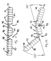
Figure 10 is a perspective view of an alternate embodiment of air mattress according to the invention cutaway at longitudinal and lateral planes therethrough. -
Figure 11 is a longitudinal cross section taken through the mattress shown inFigure 10 . -
Figure 12 is a schematic representation of the articulation provided by the mattress shown inFigures 10 and11 . - As best seen in
Figure 1 , the mattress system of the invention is generally indicated at 3. Themattress system 3 is preferably supported on amattress 5 of conventional design which is usually supported on a frame orother structure 7. It will be understood, of course, that a variety of different bed frames can be used, particularly in the hospital or home care environment where this invention is especially useful. - The mattress system comprises an inflatable portion 9 which is connected by a plurality of
hoses 11 topump 13, which supplies air through thehoses 11 to inflate the inflatable portion 9. - As best seen in
Figure 2 , the inflatable portion 9 includes an inflatable mattress generally indicated at 15 which has a laterally middle portion that comprises a plurality of laterally extending, longitudinally spacedsupport tubes 17 over the entire length of the mattress. The air mattress also comprises first and second laterally longitudinal extendingside rail tubes 19 which extend the entire length of the mattress adjacent the lateral ends of thesupport tubes 17 on either lateral side of the middle portion. Each of thetubes - The inflatable mattress is of material suitable for containing air under sufficient pressure to support a person on the inflatable portion 9. A variety of materials may be used effectively in this application, but the material is preferably a thermoplastic. Particularly preferred is polyethylene, such as the polyethylene material sold under the name "Metalecene" by Dow Chemical, Exxon or Mobil Corporation. The thickness of the polyethylene used may range from about 2 to about 25 mils, but particularly preferred is material of about 3 to 5 mils.
- To provide for a breathable environment adjacent to the skin of a person lying on the inflatable portion 9, the
mattress 15 is covered by a fill orbatting layer 21 which extends over substantially all of the upper surface of themattress 15 and is either glued or thermally bonded in place to the material ofmattress 15. A top sheet orouter layer 23 covers thefill layer 21 and the entire upper surface of themattress 15, and is bonded to the perimeter thereof, preferably by a thermal seal. - The
top sheet 23 is formed of a breathable material that permits the passage of water vapor therethrough, but which does not permit liquid water to pass and is preferably bacteria-proof. Materials of this type are known in the disposable diaper arts. Particularly effective for this purpose is micropore material such as a polyester non wovens or polypropylene saturate material. Thetop sheet 23 permits water vapor from the perspiration of the person on the mattress 9 to pass through it and enter into thefill layer 21. - The main purpose of the
fill layer 21 is to provide loft to create an air space between thetop sheet 23 and the non-breathable material of themattress 15 through which the user's water vapor can escape and then pass out of the system through thetop layer 23 in a location where this will not cause discomfort to the user.Fill layer 21 is consequently of material that allows air and water vapor to pass therethrough fairly freely, and that resists retaining much moisture. Particularly preferred materials are polyester fill, and especially preferred is Dacron. Also, generally speaking, the mechanical nature of the fill layer material is such that it is less compressible than the underlying inflatedmattress 15, so that thetubes fill layer 21, and the loft thereof is maintained despite the weight of the patient pressing thefill layer 21 againstmattress 15. - The
top sheet 23 is an integral structural part of the inflatable portion 9. The fact that thetop sheet 23 is bonded to the mattress substantially completely around its outer edge perimeter structurally ties the top sheet into the load bearing of supporting the user. The thickness of thetop sheet 23 protects themattress 15, and allows thinner material to be used in the mattress because it is protected better against puncture by thetop sheet 23. - Also, as best seen in
figure 4 , thetop sheet 23 and filllayer 21 overlie thesupport tubes 17 and depend between the adjacent peaks of thetubes 17. When the user lies on thetop sheet 23, thetop sheet 23 and filllayer 21 together act to "tent" betweenadjacent support tubes 17, providing a more supportive flat surface on the top of the mattress portion 9. - The mattress portion 9 is also provided with a
protective bottom sheet 27 of a durable material, with heavy polyester non woven material being especially desirable. Thisbottom sheet 27 protects the air mattress from being punctured from below. Thebottom sheet 27, like thetop sheet 23, is bonded to themattress 15 around virtually all of the outer perimeter edge of themattress 15, preferably in the same heat seal as is used to bond thetop sheet 23 to themattress 15.Bottom sheet 27 also cooperates structurally with themattress 15 to provide a flat and stable support surface of the mattress portion 9 for the user to lie on. - To inflate and maintain pressure in the
mattress 15, electricallypowered pump 13 supplies air under pressure throughhoses 11, which air flows intomattress 15 and inflates thesupport tubes 17 and theside rail tubes 19. Thehoses 11 are connected with longitudinally extendingair tubes 25 which define passages therein that communicate withsupport tubes 17 and transmit the air supplied by thepump 13 thereto. - In the preferred embodiment, as best seen in
Figures 3 and4 , the passages in theair supply tubes 25 extend longitudinally through themattress 15 but in onetube 25apertures 29 are provided which communicate with the interior of a set of thesupport tubes 17, and in theother tube 25,apertures 29 are provided which communicate with the remainingsupport tubes 17. In the embodiment shown inFigure 4 , one air supply tube supplies air to everyother support tube 17, and the otherair supply tube 25 supplies air to theother support tubes 17 between them. Such an arrangement affords some degree of extra reliability, because, in the event that there is a failure of air supply or a tear in asupport tube 17 of one of the sets of support tubes, the other set ofsupport tubes 17 should still retain air pressure to support the user. - Alternatively, one
air supply tube 25 may supply air to the first andlast support tubes 17, defining with the side rail tubes 19 a rectangular frame, while the remaining longitudinallyinward support tubes 17 are supplied with air by the otherair supply tube 25. Also, if desired, additionalair supply tubes 25 maybe added to the design to define other patterns of sets ofsupport tubes 17 for special purposes. - In the most common application of the invention, the mattress is inflated fully and the user lies thereon, with the
pump 13 activated only to the degree necessary to keep theair mattress 15 inflated. Increased comfort may be afforded to the user by forming small holes in the upper surface of themattress 15 so that air pumped into the mattress can flow out through theupper sheet 33 of thesupport tubes 17, and through thefill layer 21, to better ventilate the points of contact of the user's body with themattress 15. - It is an alternative aspect of invention to provide for prevention of bed sores in patients who are required to stay in bed for long periods of time, and the arrangement wherein each
air supply tube 25 supplies air to alternatingsupport tubes 17 is especially appropriate for this purpose. In this application, pump 13 alternates supplying air to one of thehoses 11 with the other of thehoses 11. By switching the supply of air from onehose 11 to the other periodically, the user is alternately supported by the "odd numbered"support tubes 17 and then the "even numbered"support tubes 17. In such an application, it is preferable that the upper surface of thesupport tubes 17 be punctured to a small degree, e.g., in pinpricks, to allow the escape of air therethrough so that deflation occurs fairly readily in tubes that are not being sent air, and also to ventilate the locations under the patient. The resulting system allows for continuous variations in the location of support of the patient, which prevents the formation of bed sores. - As best seen in
Figures 3 and4 , theair supply tubes 25 are on either side of themattress 15,.each adjacent a respectiveside rail tube 19. The passages in theair supply tubes 25 also deliver air to the adjacentside rail tube 19. The air passes from the air supply tube through aflutter valve 31 formed by the ends of the air supply tube material (Figure 3 ). These ends are heat sealed together, but intermittently so that air can flow from the passage inair tubes 25 into the interior of theside rail 19. Theflutter valves 31 are one way valves, and do not permit the air to flow back in the reverse direction, i.e. from the side rail into theair tube 25. - The
flutter valves 31 retain pressure in the side rails 19 even if the pump completely fails or if thesupport tubes 17 in the lateral middle of themattress 15 completely deflate. This is especially advantageous in a hospital situation, because the side rails 19, while still inflated, will keep a patient from simply rolling out of bed in the event themattress 15 partially deflates. - The method of fabrication of the
air mattress 15 is also a particularly desirable aspect of the present invention because the mattress is constructed as a continuous sheet of bonded materials. The process of manufacture is schematically explained inFigure 5 . It will be understood that, while one side rail construction is shown, an equivalent symmetrical construction is applied on the opposite lateral side ofmattress 15. - The first step in fabrication of the
mattress 15 is that twosheets support tubes 17, are bonded together with the foldedair tube sheet 37, which will become theair supply tube 25, by laterally extending heat seals.Sheet 37 is already provided with punchedholes 29 therein before being sealed in place. - The heat seals are applied every 4 inches along
sheet 37, because that will be the diameter of thesupport tube 17 when inflated. However, the relative lengths of top andbottom tube sheets air tube sheet 37 is greater, because the support tubes will inflate to a larger diameter. Therefore, these heat seals are applied with pleats or gussets folded into thesheets air supply tube 25. - The heat
seal bonds sheets sheet 37, but does not bond the inside faces ofsheet 37 to each other. The interior passage defined bysheet 37 is kept open to allow air to flow down the resultingtube 25. Heat sealing on the inside of the tube is prevented by the use of a Teflon or paper insert, which will not permit thesheet 37 to heat seal to itself. Alternatively, ink may be used on the inside of the foldedsheet 37, which will also prevent the heat seal from closing the interior of thetube 25. - Once this basic structure is formed, the remaining heat seals are longitudinal, and are illustrated in
Figure 5 . First, heat seals A1 and A2 are applied, bondingsupport tube sheet 33 with part ofair tube sheet 37 and a siderail top sheet 39, and bondingsupport tube sheet 35 with another part ofsheet 37 and siderail bottom sheet 41. Second, heat seal B is applied to form the flutter valve on theair supply tube 25. This seal B is not continuous, but has gaps therein which will allow air to flow through between the two parts of thesheet 37 into theside rail 19. Thirdly, the outer edge of theside rail sheets top sheet 23 andbottom cover sheet 27. Thefill layer 21 must be installed belowtop layer 23 before seal C, or, if the batting material is compatible, thefill layer 21 may also be heat sealed along the outer edge of themattress 15 together withtop sheet 23. - This fabrication process produces a continuous roll of mattress material. To make an individual mattress therefrom, the manufacturer cuts the roll material in a lateral cut to a length suitable for a mattress. At one end of the cut material, the manufacturer heat seals the open ends of the side rails 19 and the
air supply tube 25. At the other end, the manufacturer heat seals the open ends of the side rails 19, but insertshose fixtures 43 into the open ends ofair supply tubes 25 to allow thetubes 11 to pump 13 to be attached thereto. The mattress is then ready to use. - An alternate embodiment of the mattress of the invention is shown in
Figure 6 , which shares many features with the preferred embodiment. In the alternate embodiment,support tubes 45 are formed of a supporttube top sheet 47, acenter sheet 49, and abottom sheet 51. A longitudinally extending airsupply tube structure 53 is provided adjacent eachside rail 55. Thisair supply tube 53 supplies air into the upper support tube interior indicated at 56 throughaperture 57 and intoside rail 55 throughflutter valve 59. Theair supply tubes 53 preferably communicate with alternating support tubes as in the - Side rails 55 have
apertures 61 therein which communicate with the lower support tube interior of all of thesupport tubes 45, indicated at 63. Because of one-way flutter valve 59, the air in thelower interior 63 and in the side rails 55 remains pressurized even if thepump 13 fails or thetop interior 56 deflates. In such an event, the lower half of thesupport tubes 45 continues to support the user above the mattress below. - Manufacture of such a mattress is similar to the process described above, with certain adjustments to allow for the presence of the
center sheet 49. Referring toFigure 7 , in fabrication, a longitudinal heat seal D is made sealingair supply structure 53 tocenter sheet 49. Then lateral heat seals (not shown) are applied in a manner similar to that in the preferred embodiment, i.e., with the material of top andbottom sheets tube top sheet 47 with siderail top sheet 65, and join supporttube bottom sheet 51 with siderail bottom sheet 67. Intermittent seal F is applied to createflutter valve 59 leading intoside rail 55.Side rail 55 is then closed by sealing the lateral outward edge thereof, together withtop sheet 23,bottom sheet 27, and, optionally, filllayer 21, which may be sealed in the same operation if the materials are compatible. - Both the preferred embodiment and the first alternate embodiment provide for an inflatable air mattress system about 4-inches thick, the radius of the
support tubes 17. Such an air mattress is suitable for use where there is another mattress on the bed, but if no mattress is available, the 4-inch thick arrangement may not be adequately comfortable for the user. Accordingly, it may be desired to increase the thickness of the mattress. - Increasing the thickness of the mattress is possible using the structure of the alternate embodiment having the
center sheet 49. As best seen inFigure 8 , a view showing a longitudinal cross-section of further alternate embodiment, the mattress may be thickened by providing underneathcenter sheet 49enlarged support tubes 69, which have a diameter approximately twice that of theupper support tubes 45. Thelower wall 67 of theside rail 55 is also extended to increase this dimension below thecenter sheet 49. This design provides for an additional 2 inches of thickness in the mattress. -
Figure 9 shows an alternate embodiment wherein the upper andlower support tubes 45 are extended by producing longer amounts of material in thesheet - Where no mattress is provided for the bed, and all support of the user is to be provided by an inflated air mattress, it is generally preferred, particularly in hospital and home-care environments, that a mattress of at least 8 inches in height be provided.
-
Figures 10 to 12 show an alternate embodiment which provides an inflated mattress of appropriate height according to the present invention. Many aspects of this structure are similar to those of the embodiment shown inFigures 6 and 7 , and similar parts are given the same reference characters. - The upper surface of the
air mattress 71 comprises a series of laterally extendingsupport tubes 45 having a diameter of approximately 4 inches. Thesesupport tubes 45 are formed of asheet 47 secured to the upper surface of acenter sheet 73, which extends substantially the entire length and lateral width of themattress 71. - Air is supplied through air supply tubes defined by
tube structure 53, which is similar to that shown in the embodiment shown inFigure 6 . An aperture or punchhole 57 in thestructure 53 allows air pumped therein to enter into the upper support tube interior space indicated at 56. A side rail 75 is provided on each lateral side of themattress 71.Flutter valve structure 77 permits air in thepassage 53 to also pass into upper side railinterior space 79. -
Center sheet 73 extends below the upper side rail 75 toouter wall 81 of theair mattress 71 and is secured thereto. For distribution of air,center sheet 73 is provided in the region of the side rail 75 with a plurality of apertures or punchholes 83 through which air may pass from theinterior space 79 of the side rail 75 down into a lower interior space generally indicated at 85, in theair mattress 71. Thelower space 85 of theair mattress 71 is defined by thecover sheet 73, theside wall 81, abottom enclosure sheet 87. In order to support theupper surface tubes 45 of the mattress so that there is not an undue amount of lateral or longitudinal movement possible, a plurality ofsupport panels 89 are provided linking thebottom closure sheet 87 with thecenter sheet 73. At the longitudinal ends of the mattress the panel is extended to seal against theside wall 81, to fully enclose the lower space. - In the event of a failure of the
pump 13, which supplies air to theair supply passage 53, or in the event of a rupture of the upper surface of the mattress causing deflation ofsupport tubes 45, the side rail 75 remains inflated due to the one-way passage of air influtter valve 77, which prevents air in the side railinterior space 79 from passing back into theair supply passage 53. Furthermore, becauseside rail space 79 communicates with thelower space 85 of the mattress throughaperture 83, air in thelower space 85 also is prevented from leaving. - As a consequence, in the event of a failure of the
pump 13 or theupper support tubes 45, themattress 71 will still retain air therein, and the patient will lie on a flat surface defined bycover sheet 73, supported on inflatedlower space 85, and between inflated side rails 75 which will also remain inflated. This of course is especially important where the inflatable mattress is used on a bare surface or bedspring, to prevent a rupture from dropping onto an uncomfortable surface below themattress 71. - Where the
mattress 71 is used in an environment with a bed with some articulation, such as a hospital or home-care bed, the thickness of themattress 71 does not admit to easy folding. Accordingly, as best shown inFigures 11 and 12 , thebottom sheet 87 and theside walls 81 are interrupted in two locations to create an articulating recess generally indicated at 93. At these recesses, thelower surface sheet 87 extends up tocenter sheet 73, as a slopingbottom wall 95 on either side of therecess 93, which allows substantial bending movement, as seen inFigure 12 . - Construction of the
mattress 71 of this alternate embodiment with respect to the top portion of theair mattress 71, i.e., that portion that is above thecenter sheet 73, is accomplished using methods similar to those described with respect to the embodiment shown inFigures 6 and 7 . The lower portion, i.e., the side andbottom walls support panels 89 and end walls 91, are assembled by a process which should be apparent to those knowledgeable in the art. - The foregoing specification has been couched in terms which should be viewed as descriptive rather than limiting, as those with skill in the art, having this specification before them, will be able to make modifications and variations to the structure thereof without departing from the scope of the invention here disclosed.
- The following is a list of the preferred embodiments of the present invention:
- 1. An inflatable mattress system comprising:
- an inflatable mattress of a material that is substantially impermeable to water vapor and can support the weight of a human being thereon by containment of air therein, said mattress having longitudinal and lateral ends defining a perimeter thereof;
- a breathable fill sheet overlying the mattress, said fill sheet permitting the passage of air and water vapor therethrough;
- a top sheet having a perimeter overlying the fill sheet, said top sheet being of a material that permits the passage of air or water vapor therethrough, but that blocks the passage of liquid water therethrough;
- at least a portion of said top sheet being permanently bonded to at least a portion of the perimeter of the mattress so that when a person lies on the mattress system, water vapor between the person and the top sheet can pass through the top sheet and through the fill sheet to a portion of the support mattress displaced from the person lying thereon.
- 2. The mattress system of 1, and
- said top sheet being breathable micropore material.
- 3. The mattress system of 2, and
- said top sheet being of polymer non-woven material or polypropylene saturate material.
- 4. The mattress system of 1, and
- said fill sheet being of polyester fill.
- 5. The mattress system of 1, and
- said mattress being of polyethylene.
- 6. The mattress system of 1, and
- said top sheet and said mattress being bonded together around substantially all of the perimeters thereof.
- 7. The mattress system of 1, and
- said top sheet, said fill layer and said mattress being bonded together at said parameters by a seal.
- 8. The mattress system of 1, and
- the mattress being configured and inflated, and the fill sheet being selected of such a material, such that the compressibility of the fill sheet is less than that of the mattress so that the weight of the person does not compress the fill sheet against the mattress and block the breathability of the fill sheet
- 9. The mattress system of 1, and
- a pump supplying air to the mattress.
- 10. The mattress system of 9, and
- said mattress including an upper sheet, said upper sheet having perforations therein through which air in the mattress flows to pass through a portion of the fill layer for providing ventilation, said perforations being small enough that adequate pressure in the mattress is maintained to support a user thereon.
- 11. The mattress system of 9, and
- said mattress having an upper and a lower sheet attached to each other so as to form a series of laterally extending inflated tubular structures, and a first air supply passage receiving air from said pump and transmitting said air to a set of said tubular structures for inflation thereof.
- 12. The mattress system of 11, and
- a second air supply passage receiving air from the pump and transmitting the air to a second set of said tubular structures different from said first set.
- 13. The mattress system of 12, and
- said pump alternately supplying air to one of the air supply passages and then to the other of the air supply passages.
- 14. The mattress system of 1, and
- said mattress including a middle portion with two lateral sides a pair of longitudinally extending side tubes, each on respective lateral sides of said middle portion, said side tubes receiving air from said middle portion for inflation thereof through a one-way air flow structure, so that in the event of a reduction of pressure in the middle portion, the side tubes remain inflated
- 15. The mattress system of 14, and
- said middle portion having an upper and a lower chamber therein, which are inflated when the mattress is inflated, said chambers communicating with each other via said one-way air flow structure or another one-way air flow arrangement so that one of the chambers can be ruptured or lose air pressure without causing immediate deflation of the other chamber.
- 16. An inflatable mattress comprising:
- first and second sheets of polymeric material extending longitudinally and laterally and being secured together to form longitudinally spaced laterally extending support tubes;
- said support tubes being pneumatically enclosed so as to be able to contain air therein at a pressure sufficient to support a person lying on the mattress; and
- said support tubes having lateral ends wherein the material of the tubes is gathered together in gussets and the sheets of polymeric material are bonded together, allowing the support tube to inflate to a generally cylindrical shape.
- 17. The mattress of 16, and
- said sheets having therebetween a first air passage communicating with a plurality of said support tubes so that air may be supplied to said support tubes through said air passage to inflate or maintain air pressure in said support tubes.
- 18. The mattress of 17, and
- said sheets having a second passage therebetween communicating with others of the support tubes and allowing delivery of air thereto.
- 19. The mattress of 18, and
- said first passage communicating with the support tubes at longitudinal ends of the mattress, to provide an inflated head and foot of the mattress, and the second passage communicating with the support tubes therebetween.
- 20. The mattress of 18. and
- said first and second passages communicating with alternating support tubes over the longitudinal length of the mattress.
- 21. The mattress of 16, and further comprising:
- first and second laterally spaced longitudinally extending side tubes each having an interior and each being connected with a respective set of the lateral ends of the support tubes.
- 22. The mattress of 21, and
- side rail air flow structure connected with the sheets and defining passages communicating with the interiors of the side tubes so that air introduced between the sheets can pass into the side tubes.
- 23. The mattress of 22, and
- said side rail air flow structures being configured so that air can flow therethrough only into, and not out of, the interiors of the side tubes.
- 24. The mattress of 23, and
- said side rail air flow structures including one-way flutter valve structures.
- 25. The mattress of 16, and
- a center sheet bonded between the two sheets of polymeric material, said center sheet defining in each of the support tubes a lower tube interior and an upper tube interior.
- 26. The mattress of 25 and further comprising:
- air flow means permitting passage of air in the upper tube interior into the lower tube interior.
- 27. The mattress of 26, and
- said air flow means preventing passage of air in the lower tube interior into the upper tube interior so that, in the event of a loss of pressure in the upper tube interior, pressure is nonetheless maintained in the lower tube interior.
- 28. The mattress of 19. and
- an air flow structure forming a tube extending generally longitudinally between the first and second sheets and defining a passage therein communicating with some of the support tubes to permit supply of air thereto.
- 29. The mattress of 28, and
- a second air flow structure forming a second tube extending generally longitudinally between the first and second sheets and defining therein a second passage communicating with others of the support tubes.
- 30. The mattress of 29, and
- first and second laterally spaced, longitudinally extending side tubes adjacent respective lateral ends of the support tubes, said first and second passages each communicating with a respective side tube for supplying air thereto.
- 31. The mattress of 30, and
- one-way flow structures between the side tubes and the associated passages so that air can flow only from the passage into the associated side tube, and not in the opposite direction, so that said side rails do not immediately deflate when pressure leaves the passage.
- 32. The mattress of 31, and said air flow means including means defining apertures connecting the side tubes with the lower tube interiors so that the side tubes and the lower tube interiors remain inflated even when air is not supplied through the passages.
- 33. The mattress of 16, and a fill layer of porous material overlying the upper sheet of polymeric material, and
- a top sheet overlying the fill layer and being connected with the support tubes to remain in place thereon, said top sheet being of a material that prevents the passage of liquid water but allows the passage of water vapor, whereby water vapor for a user lying on the mattress can pass through the top layer, through the fill layer, and away from the user.
- 34. The mattress of 33, and
- said fill layer and top sheet tenting between high points of the support tubes and providing support of the user therebetween.
- 35. An inflatable mattress system comprising
- an inflatable mattress; and
- a pump supplying air to the inflatable mattress for inflation thereof;
- the inflatable mattress comprising
- a middle portion receiving air from the pump and being inflated thereby, said middle portion having two lateral sides;
- a pair of side tubes each attached to a respective side of the middle portion;
- said middle portion including air flow structures transmitting air in the middle portion to the side tubes, said air flow structures blocking air flow therethrough from the side tubes to the middle portion so that, when the middle portion deflates or loses air pressure therein, the side tubes remain inflated.
- 36. The mattress system of 35, and
- said middle portion defining therein an interior space, said middle portion including a center sheet dividing said interior space into one or more upper spaces and one or more lower spaces.
- 37. The mattress system according to 36, and
- said middle portion comprising a bottom sheet defining said lower space or spaces therewith.
- 38. The mattress system according to 37, and
- said bottom sheet being connected to a lower surface of said center sheet in a plurality of locations so as to define said lower spaces.
- 39. The mattress system of 38, and
- said bottom sheet being connected to the center sheet so as to form downwardly disposed recesses extending laterally across the mattress so as to provide for easier bending of said mattress on an articulated bed frame.
- 40. The mattress system according to 38, and
- said middle portion having an upper sheet connected to an upper surface of said center sheet in a plurality of locations so as to form a plurality of laterally extending upper support tubes defining the upper spaces.
- 41. The mattress system according to 40, and
- the upper sheet, the center sheet, and the bottom sheet all being bonded together in laterally extending seals so as to form a plurality of support tubes between said side tubes.
- 42. The mattress system according to 40, and
- the side tubes each having an interior communicating with the lower spaces of the lower support tubes so that air flows therebetween, and so that, if the upper support tubes lose air pressure, the lower support tubes and the side tubes remain inflated.
- 43. The mattress system of 36, and
- said side tubes each having an interior communicating with the lower spaces so that, in the event of a loss of pressure in the upper spaces, the middle portion lower spaces and the side tubes remain inflated.
- 44. A mattress system according to 40, and said mattress further comprising:
- a fill sheet of porous material overlying the support tubes;
- a top sheet overlying the fill layer and being connected with the support tubes to remain in place thereon, said top sheet being of a material that prevents the passage of liquid water but allows the passage of water vapor, whereby water vapor for a user lying on the mattress can pass through the top layer, through the fill layer, and away from the user.
- 45. A mattress according to 44, and
- said fill layer and top sheet tenting between high points of the support tubes and providing support of the user therebetween.
- 46. A method of manufacturing an inflatable air mattress, said method comprising:
- forming a generally longitudinally continuous mattress precursor stock of a substantially airtight material, said stock including a series of longitudinally spaced laterally extending tube structures each having two lateral ends and an interior, and
- cutting said precursor stock at a location suitable for the length of the inflatable mattress.
- 47. The method of 46, and
- said precursor stock further including a passage structure defining a continuous longitudinally extending passage in the stock communicating with interior of some of the tube structures; and
- said method further comprising
- sealing said passage closed to permit inflation therewith.
- 48. The method of 47, and
- said precursor stock having a second structure defining a second continuous longitudinally extending passage in the stock communicating with others of the tubular structures, and
- sealing said second passage closed to permit inflation therewith.
- 49. The method of 48, and
- inserting into said first and second passages fixtures adapted to connect with hoses supplying air to said passages for inflating the mattress.
- 50. The method of 47, and
- said forming of said precursor stock including bonding first and second sheets of airtight material together with laterally extending seals to form said tubular structures.
- 51. The method of 50, and
- said structure defining said passage to extend through said seals without interruption.
- 52. The method of 51, and
- said passage being kept open through said seals by an insert placed therein during forming of the seals or by coating a surface of the structure defining the passage with a substance, such as ink, to prevent bonding therein during the forming of the seals.
- 53. The method of 46, and
- said stock being formed to have a pair of longitudinally extending side tubes each adjacent a respective set of lateral ends of the support tubes.
- 54. The method of 47, and
- said stock being formed to have a pair of longitudinally extending side tubes each adjacent a respective set of lateral ends of the support tubes.
- 55. The method of 54, and
- said sealing including sealing longitudinal ends of the side tubes after the cutting so that air does not escape therefrom when the mattress is inflated.
- 56. The method of 46, and
- said forming of the stock including applying a fill sheet over said tube structures and a top sheet extending thereabove, said top sheet being bonded to lateral edges of the air mattress, and being of a water vapor permeable, and liquid water impermeable sheet material.
- 57. The method of 48, and
- one of said passages communicating with the set of every second tube structure and the other of said passages communicating with the other tube structures.
Claims (15)
- An inflatable mattress comprising:first and second sheets of polymeric material extending longitudinally and laterally andbeing secured together to form longitudinally spaced laterally extending support tubes;said support tubes being pneumatically enclosed so as to be able to contain air therein at a pressure sufficient to support a person lying on the mattress; andsaid support tubes having lateral ends wherein the material of the tubes is gathered together in gussets and the sheets of polymeric material are bonded together, allowing the support tube to inflate to a generally cylindrical shape.
- The mattress of Claim 1, and
said sheets having therebetween a first air passage communicating with a plurality of said support tubes so that air may be supplied to said support tubes through said air passage to inflate or maintain air pressure in said support tubes. - The mattress of Claim 2, and
said sheets having a second passage therebetween communicating with others of the support tubes and allowing delivery of air thereto. - The mattress of claim 1, and further comprising:first and second laterally spaced longitudinally extending side tubes each having an interior and each being connected with a respective set of the lateral ends of the support tubes.
- The mattress of claim 4, and
side rail air flow structure connected with the sheets and defining passages communicating with the interiors of the side tubes so that air introduced between the sheets can pass into the side tubes. - The mattress of claim 1, and
a center sheet bonded between the two sheets of polymeric material, said center sheet defining in each of the support tubes a lower tube interior and an upper tube interior. - The mattress of claim 6 and further comprising:air flow means permitting passage of air in the upper tube interior into the lower tube interior.
- The mattress of claim 1, and a fill layer of porous material overlying the upper sheet of polymeric material, and
a top sheet overlying the fill layer and being connected with the support tubes to remain in place thereon, said top sheet being of a material that prevents the passage of liquid water but allows the passage of water vapor, whereby water vapor for a user lying on the mattress can pass through the top layer, through the fill layer, and away horn the user. - An inflatable mattress system comprising
an inflatable mattress; and
a pump supplying air to the inflatable mattress for inflation thereof;
the inflatable mattress comprising
a middle portion receiving air from the pump and being inflated thereby, said middle portion having two lateral sides;
a pair of side tubes each attached to a respective side of the middle portion;
said middle portion including air flow structures transmitting air in the middle portion to the side tubes, said air flow structures blocking air flow therethrough from the side tubes to the middle portion so that, when the middle portion deflates or loses air pressure therein, the side tubes remain inflated. - The mattress system of claim 9, and
said middle portion defining therein an interior space, said middle portion including a center sheet dividing said interior space into one or more upper spaces and one or more lower spaces. - The mattress system according to claim 10, and
said middle portion comprising a bottom sheet defining said lower space or spaces therewith. - The mattress system according to claim 11, and
said bottom sheet being connected to a lower surface of said center sheet in a plurality of locations so as to define said lower spaces. - A method of manufacturing an inflatable air mattress, said method comprising:forming a generally longitudinally continuous mattress precursor stock of a substantially airtight material, said stock including a series of longitudinally spaced laterally extending tube structures each having two lateral ends and an interior; andcutting said precursor stock at a location suitable for the length of the inflatable mattress.
- The method of claim 13, and
said precursor stock further including a passage structure defining a continuous longitudinally extending passage in the stock communicating with interior of some of the tube structures; and
said method further comprising sealing said passage closed to permit inflation therewith. - The method of claim 14, and
said precursor stock having a second structure defining a second continuous longitudinally extending passage in the stock communicating with others of the tubular structures, and
sealing said second passage closed to permit inflation therewith.
Applications Claiming Priority (2)
| Application Number | Priority Date | Filing Date | Title |
|---|---|---|---|
| US09/563,995 US6775868B1 (en) | 2000-05-03 | 2000-05-03 | Inflatable mattress systems and method of manufacture thereof |
| EP01110764A EP1151698B1 (en) | 2000-05-03 | 2001-05-03 | Inflatable mattress systems and method of manufacture therefor |
Related Parent Applications (2)
| Application Number | Title | Priority Date | Filing Date |
|---|---|---|---|
| EP01110764A Division EP1151698B1 (en) | 2000-05-03 | 2001-05-03 | Inflatable mattress systems and method of manufacture therefor |
| EP01110764.6 Division | 2001-05-03 |
Publications (3)
| Publication Number | Publication Date |
|---|---|
| EP2014200A2 true EP2014200A2 (en) | 2009-01-14 |
| EP2014200A3 EP2014200A3 (en) | 2010-12-22 |
| EP2014200B1 EP2014200B1 (en) | 2015-01-28 |
Family
ID=24252735
Family Applications (2)
| Application Number | Title | Priority Date | Filing Date |
|---|---|---|---|
| EP08008678.8A Expired - Lifetime EP2014200B1 (en) | 2000-05-03 | 2001-05-03 | Inflatable mattress systems and method of manufacture thereof |
| EP01110764A Expired - Lifetime EP1151698B1 (en) | 2000-05-03 | 2001-05-03 | Inflatable mattress systems and method of manufacture therefor |
Family Applications After (1)
| Application Number | Title | Priority Date | Filing Date |
|---|---|---|---|
| EP01110764A Expired - Lifetime EP1151698B1 (en) | 2000-05-03 | 2001-05-03 | Inflatable mattress systems and method of manufacture therefor |
Country Status (4)
| Country | Link |
|---|---|
| US (2) | US6775868B1 (en) |
| EP (2) | EP2014200B1 (en) |
| AT (1) | ATE505980T1 (en) |
| DE (1) | DE60144458D1 (en) |
Families Citing this family (41)
| Publication number | Priority date | Publication date | Assignee | Title |
|---|---|---|---|---|
| WO2000040124A1 (en) | 1999-01-08 | 2000-07-13 | Hill-Rom, Inc. | Mattress assembly |
| US7174589B2 (en) * | 2000-05-03 | 2007-02-13 | Trlby Innovative Llc | Inflatable cushion systems and method of manufacture thereof |
| GB0026404D0 (en) * | 2000-10-28 | 2000-12-13 | Siddall & Hilton Ltd | Body support arrangements |
| US7021008B2 (en) * | 2003-01-10 | 2006-04-04 | Busby Tyler E | Inflatable structure with inflatable interior frame |
| US6971133B2 (en) * | 2003-05-09 | 2005-12-06 | See Ronald A | Air mattress apparatus |
| US6898809B2 (en) * | 2003-08-11 | 2005-05-31 | Woodlark Circle, Inc. | Air mattress with single perimeter seam |
| US20050172412A1 (en) * | 2004-02-10 | 2005-08-11 | Pearson Jon D. | Inflatable device for adjusting the support and comfort of a mattress |
| US8276222B1 (en) | 2005-01-14 | 2012-10-02 | Smart Medical Technology, Inc. | Patient transfer kit |
| US7735164B1 (en) * | 2005-01-14 | 2010-06-15 | Smart Medical Technology, Inc. | Disposable patient transfer mattress |
| WO2006085109A2 (en) * | 2005-02-14 | 2006-08-17 | Pegasus Limited | Alternating pressure mattresses |
| US6990701B1 (en) | 2005-08-05 | 2006-01-31 | Vera Litvak | Sectional non-slip mattress |
| KR20080036635A (en) * | 2005-08-25 | 2008-04-28 | 가부시키가이샤 모루텐 | Air mattress |
| US7914611B2 (en) | 2006-05-11 | 2011-03-29 | Kci Licensing, Inc. | Multi-layered support system |
| TW200823116A (en) * | 2006-11-17 | 2008-06-01 | Yao-Sin Liao | Air enclosure with independent double-layer air chambers |
| US20090144904A1 (en) * | 2007-12-10 | 2009-06-11 | David Moye | Inflatable hospital bed and method of using same |
| US8490226B2 (en) | 2008-09-19 | 2013-07-23 | Diacor, Inc. | Systems for patient transfer, devices for movement of a patient, and methods for transferring a patient for treatment |
| GB0821066D0 (en) * | 2008-11-18 | 2008-12-24 | Psp Technology Ltd | Pneumatic mattress |
| KR20110086859A (en) | 2008-11-19 | 2011-08-01 | 케이씨아이 라이센싱 인코포레이티드 | Multi-layered support system and method thereof |
| US20110145996A1 (en) * | 2009-12-22 | 2011-06-23 | Kara Johan | Reversible Foam Mattress and Method of Construction |
| EP2377503B1 (en) * | 2010-04-15 | 2012-11-28 | Tsung Hsi Liu | Process for manufacturing an air mattress with multiple air passages |
| US20110252571A1 (en) * | 2010-04-15 | 2011-10-20 | Liu Tsung Hsi | Multiple air passages applied to air mattress |
| US8852131B2 (en) * | 2010-09-15 | 2014-10-07 | Anodyne Medical Device, Inc. | Support surface system providing simultaneous alternating pressure and low air loss therapies |
| US8918930B2 (en) | 2011-01-04 | 2014-12-30 | Huntleigh Technology Limited | Methods and apparatuses for low-air-loss (LAL) coverlets and airflow units for coverlets |
| US8336143B2 (en) | 2011-04-29 | 2012-12-25 | Clayton Lemmer | Air mattress |
| JP5855748B2 (en) | 2011-07-28 | 2016-02-09 | ハントリー テクノロジー リミテッド | Multi-layer support system |
| JP5780643B2 (en) * | 2011-07-28 | 2015-09-16 | 住友理工株式会社 | mattress |
| WO2013052495A1 (en) | 2011-10-03 | 2013-04-11 | Kci Licensing, Inc. | Multi-layered support system |
| US20130212808A1 (en) * | 2012-02-21 | 2013-08-22 | Charles A. Lachenbruch | Topper with Targeted Fluid Flow Distribution |
| US10166160B2 (en) * | 2012-02-21 | 2019-01-01 | Qfix Systems, Llc | Air bearing device and method for transferring patients |
| GB2503887A (en) * | 2012-07-10 | 2014-01-15 | Gary Baker | A bed assembly with a dynamic mattress and a sprung base. |
| US10537185B2 (en) * | 2014-03-18 | 2020-01-21 | Dreamwell, Ltd. | Accelerated calibration system for a smart response technology mattress |
| US10716409B2 (en) * | 2014-05-22 | 2020-07-21 | Dreamwell, Ltd. | Smart response technology mattress |
| GB2524203B (en) * | 2014-07-29 | 2016-02-03 | Direct Healthcare Services Ltd | Mattress |
| US20160245439A1 (en) * | 2015-02-23 | 2016-08-25 | Brandon C. Fry | Air leak repair hose for inflatable mattress |
| US10871005B2 (en) | 2015-06-30 | 2020-12-22 | Inger Olivo | Portable, inflatable mattress with tent attachment |
| US9913767B2 (en) * | 2015-06-30 | 2018-03-13 | G2C Technologies | Portable, inflatable mattress for lifting and transporting corpses |
| CN105615393A (en) * | 2016-02-23 | 2016-06-01 | 浙江大自然旅游用品有限公司 | Air inflation product and air inflation product welding process |
| GB2562039A (en) * | 2017-04-25 | 2018-11-07 | Gbuk Group Ltd | Inflatable mattress and systems |
| WO2019075636A1 (en) * | 2017-10-17 | 2019-04-25 | Bestway Inflatables & Material Corp. | Inflation system and device |
| FR3084010B1 (en) * | 2018-07-23 | 2020-07-17 | Paris Sciences Et Lettres - Quartier Latin | PNEUMATIC STRUCTURE AND MANUFACTURING METHOD THEREOF |
| KR102359301B1 (en) * | 2020-02-28 | 2022-02-08 | 주식회사 에이치엠씨네트웍스 | A care system and method using wearable device |
Citations (4)
| Publication number | Priority date | Publication date | Assignee | Title |
|---|---|---|---|---|
| GB2267217A (en) * | 1992-05-29 | 1993-12-01 | Kenneth Caldwell | "Air support systems" |
| WO1995031920A1 (en) * | 1994-05-25 | 1995-11-30 | Egerton Hospital Equipment Limited | Improvements in and relating to low air-loss mattresses |
| DE29717204U1 (en) * | 1997-09-26 | 1998-10-22 | Pieczyk Peter | Inflatable mattress |
| US5890245A (en) * | 1996-11-05 | 1999-04-06 | Therapy Concepts, Inc. | Disposable ventilating mattress and method of making same |
Family Cites Families (23)
| Publication number | Priority date | Publication date | Assignee | Title |
|---|---|---|---|---|
| US2604641A (en) * | 1947-02-11 | 1952-07-29 | Stanley F Reed | Inflatable mattress |
| US2703770A (en) * | 1952-04-15 | 1955-03-08 | Melzer Jean | Manufacture of flat inflatable objects |
| AU458068B2 (en) | 1971-02-05 | 1975-01-30 | YAT CHUEN YUEN and KIN SUN YUEN | Inflatable mattresses and cushions |
| GB1341325A (en) | 1971-07-09 | 1973-12-19 | Scales J T | Inflatable support appliance |
| GB1596157A (en) | 1976-11-08 | 1981-08-19 | Nat Res Dev | Support appliances |
| US4371999A (en) | 1980-11-18 | 1983-02-08 | Keith Reid | Air mattresses |
| US4422194A (en) * | 1981-08-24 | 1983-12-27 | Connecticut Artcraft Corp. | Fluid filled body supporting device |
| US4541135A (en) | 1984-04-16 | 1985-09-17 | Victor Karpov | Air mattress |
| FR2601874B1 (en) * | 1986-07-25 | 1991-09-06 | Dijon Centre Hospitalier Rgl | INFLATABLE ANTI-PRESSURIZED MATTRESS WITH ALTERNATE INFLATABLE PADS |
| US4896389A (en) * | 1988-06-10 | 1990-01-30 | S.S.I. Medical Services Of Canada Inc. | Inflatable air mattress |
| US4999074A (en) * | 1989-01-31 | 1991-03-12 | Afeyan Industries Inc. | Method for the production of an air mattress |
| US4908895A (en) | 1989-03-20 | 1990-03-20 | Walker Robert A | Air mattress |
| US5168589A (en) * | 1989-04-17 | 1992-12-08 | Kinetic Concepts, Inc. | Pressure reduction air mattress and overlay |
| US4991244A (en) | 1990-01-05 | 1991-02-12 | Walker Robert A | Border for air bed |
| US5044030A (en) | 1990-06-06 | 1991-09-03 | Fabrico Manufacturing Corporation | Multiple layer fluid-containing cushion |
| US5561875A (en) * | 1992-02-20 | 1996-10-08 | Crown Therapeutics, Inc. | Vacuum/heat formed cushion supported on a fluid permeable manifold |
| US5421044A (en) | 1993-08-27 | 1995-06-06 | Steensen; Steen W. | Air bed |
| GB9410490D0 (en) * | 1994-05-25 | 1994-07-13 | Egerton Hospital Equip | Improvements in and relating to beds and apparatus for use therewith |
| US5560056A (en) | 1995-01-27 | 1996-10-01 | Tai; Tsai-Ting | Multiple-purpose hammock, chair, and float type apparatus |
| US5727270A (en) | 1995-06-07 | 1998-03-17 | Airceltec Inc. | Valveless self sealing fluid or gas container |
| US5720061A (en) | 1997-01-28 | 1998-02-24 | Giori; Janine | Female anatomical mattress |
| US5956787A (en) * | 1997-10-31 | 1999-09-28 | James; Ingrid B. | Anti-decubitus pneumatic mattress |
| WO2000040124A1 (en) * | 1999-01-08 | 2000-07-13 | Hill-Rom, Inc. | Mattress assembly |
-
2000
- 2000-05-03 US US09/563,995 patent/US6775868B1/en not_active Expired - Lifetime
-
2001
- 2001-05-03 AT AT01110764T patent/ATE505980T1/en not_active IP Right Cessation
- 2001-05-03 EP EP08008678.8A patent/EP2014200B1/en not_active Expired - Lifetime
- 2001-05-03 DE DE60144458T patent/DE60144458D1/en not_active Expired - Lifetime
- 2001-05-03 EP EP01110764A patent/EP1151698B1/en not_active Expired - Lifetime
-
2004
- 2004-08-17 US US10/919,858 patent/US7455744B2/en not_active Expired - Lifetime
Patent Citations (4)
| Publication number | Priority date | Publication date | Assignee | Title |
|---|---|---|---|---|
| GB2267217A (en) * | 1992-05-29 | 1993-12-01 | Kenneth Caldwell | "Air support systems" |
| WO1995031920A1 (en) * | 1994-05-25 | 1995-11-30 | Egerton Hospital Equipment Limited | Improvements in and relating to low air-loss mattresses |
| US5890245A (en) * | 1996-11-05 | 1999-04-06 | Therapy Concepts, Inc. | Disposable ventilating mattress and method of making same |
| DE29717204U1 (en) * | 1997-09-26 | 1998-10-22 | Pieczyk Peter | Inflatable mattress |
Also Published As
| Publication number | Publication date |
|---|---|
| EP2014200B1 (en) | 2015-01-28 |
| DE60144458D1 (en) | 2011-06-01 |
| US6775868B1 (en) | 2004-08-17 |
| ATE505980T1 (en) | 2011-05-15 |
| EP1151698B1 (en) | 2011-04-20 |
| EP2014200A3 (en) | 2010-12-22 |
| US20070226912A1 (en) | 2007-10-04 |
| EP1151698A2 (en) | 2001-11-07 |
| EP1151698A3 (en) | 2002-09-18 |
| US7455744B2 (en) | 2008-11-25 |
Similar Documents
| Publication | Publication Date | Title |
|---|---|---|
| US6775868B1 (en) | Inflatable mattress systems and method of manufacture thereof | |
| CA2577693C (en) | Inflatable cushion systems and method of manufacture thereof | |
| US8261387B2 (en) | Self inflating air mattress | |
| US5493742A (en) | Ventilating air mattress with an inflating quilted pad | |
| US8635726B2 (en) | Cushion bladder with middle layer having gaps and various positioned interior welds | |
| US5701621A (en) | Liner for overlaying a mattress | |
| US4777679A (en) | Inflatable cushion with central opening | |
| US5991949A (en) | Hoseless air bed | |
| US6782574B2 (en) | Air-powered low interface pressure support surface | |
| US4944060A (en) | Mattress assembly for the prevention and treatment of decubitus ulcers | |
| US5129115A (en) | Method of prefilling and supporting person on fluid filled body support system | |
| EP0878150A2 (en) | Inflatable support | |
| CA2849430C (en) | Patient/invalid support | |
| JP2008543351A (en) | Inflatable parts for alternating pressure mattress | |
| US20070101506A1 (en) | Disposable inflatable mattress | |
| EP2811865B1 (en) | Expandable structure constructed from sealed films | |
| JP2001161759A5 (en) | ||
| JP5086703B2 (en) | Air mat | |
| JP4670114B2 (en) | Air mat | |
| JPH0370564A (en) | Massage mat | |
| JPH0728894B2 (en) | Air mat to prevent bedsores | |
| EP0993818A2 (en) | Inflatable patient supports | |
| JPH0451787Y2 (en) | ||
| JPH0212987Y2 (en) | ||
| JPH07111931A (en) | Air bed |
Legal Events
| Date | Code | Title | Description |
|---|---|---|---|
| PUAI | Public reference made under article 153(3) epc to a published international application that has entered the european phase |
Free format text: ORIGINAL CODE: 0009012 |
|
| 17P | Request for examination filed |
Effective date: 20080508 |
|
| AC | Divisional application: reference to earlier application |
Ref document number: 1151698 Country of ref document: EP Kind code of ref document: P |
|
| AK | Designated contracting states |
Kind code of ref document: A2 Designated state(s): AT BE CH CY DE DK ES FI FR GB GR IE IT LI LU MC NL PT SE TR |
|
| PUAL | Search report despatched |
Free format text: ORIGINAL CODE: 0009013 |
|
| AK | Designated contracting states |
Kind code of ref document: A3 Designated state(s): AT BE CH CY DE DK ES FI FR GB GR IE IT LI LU MC NL PT SE TR |
|
| AKX | Designation fees paid |
Designated state(s): AT BE CH CY DE DK ES FI FR GB GR IE IT LI LU MC NL PT SE TR |
|
| REG | Reference to a national code |
Ref country code: DE Ref legal event code: R079 Ref document number: 60149226 Country of ref document: DE Free format text: PREVIOUS MAIN CLASS: A47C0027080000 Ipc: A47C0027000000 |
|
| GRAP | Despatch of communication of intention to grant a patent |
Free format text: ORIGINAL CODE: EPIDOSNIGR1 |
|
| RIC1 | Information provided on ipc code assigned before grant |
Ipc: A47C 27/10 20060101ALI20140731BHEP Ipc: A47C 27/00 20060101AFI20140731BHEP |
|
| INTG | Intention to grant announced |
Effective date: 20140829 |
|
| GRAS | Grant fee paid |
Free format text: ORIGINAL CODE: EPIDOSNIGR3 |
|
| GRAA | (expected) grant |
Free format text: ORIGINAL CODE: 0009210 |
|
| AC | Divisional application: reference to earlier application |
Ref document number: 1151698 Country of ref document: EP Kind code of ref document: P |
|
| AK | Designated contracting states |
Kind code of ref document: B1 Designated state(s): AT BE CH CY DE DK ES FI FR GB GR IE IT LI LU MC NL PT SE TR |
|
| REG | Reference to a national code |
Ref country code: GB Ref legal event code: FG4D |
|
| REG | Reference to a national code |
Ref country code: CH Ref legal event code: EP |
|
| REG | Reference to a national code |
Ref country code: IE Ref legal event code: FG4D |
|
| REG | Reference to a national code |
Ref country code: DE Ref legal event code: R096 Ref document number: 60149226 Country of ref document: DE Effective date: 20150312 |
|
| REG | Reference to a national code |
Ref country code: AT Ref legal event code: REF Ref document number: 707861 Country of ref document: AT Kind code of ref document: T Effective date: 20150315 |
|
| REG | Reference to a national code |
Ref country code: AT Ref legal event code: MK05 Ref document number: 707861 Country of ref document: AT Kind code of ref document: T Effective date: 20150128 |
|
| REG | Reference to a national code |
Ref country code: NL Ref legal event code: VDEP Effective date: 20150128 |
|
| PG25 | Lapsed in a contracting state [announced via postgrant information from national office to epo] |
Ref country code: SE Free format text: LAPSE BECAUSE OF FAILURE TO SUBMIT A TRANSLATION OF THE DESCRIPTION OR TO PAY THE FEE WITHIN THE PRESCRIBED TIME-LIMIT Effective date: 20150128 Ref country code: ES Free format text: LAPSE BECAUSE OF FAILURE TO SUBMIT A TRANSLATION OF THE DESCRIPTION OR TO PAY THE FEE WITHIN THE PRESCRIBED TIME-LIMIT Effective date: 20150128 Ref country code: FI Free format text: LAPSE BECAUSE OF FAILURE TO SUBMIT A TRANSLATION OF THE DESCRIPTION OR TO PAY THE FEE WITHIN THE PRESCRIBED TIME-LIMIT Effective date: 20150128 |
|
| PG25 | Lapsed in a contracting state [announced via postgrant information from national office to epo] |
Ref country code: AT Free format text: LAPSE BECAUSE OF FAILURE TO SUBMIT A TRANSLATION OF THE DESCRIPTION OR TO PAY THE FEE WITHIN THE PRESCRIBED TIME-LIMIT Effective date: 20150128 Ref country code: GR Free format text: LAPSE BECAUSE OF FAILURE TO SUBMIT A TRANSLATION OF THE DESCRIPTION OR TO PAY THE FEE WITHIN THE PRESCRIBED TIME-LIMIT Effective date: 20150429 Ref country code: NL Free format text: LAPSE BECAUSE OF FAILURE TO SUBMIT A TRANSLATION OF THE DESCRIPTION OR TO PAY THE FEE WITHIN THE PRESCRIBED TIME-LIMIT Effective date: 20150128 |
|
| REG | Reference to a national code |
Ref country code: DE Ref legal event code: R097 Ref document number: 60149226 Country of ref document: DE |
|
| PG25 | Lapsed in a contracting state [announced via postgrant information from national office to epo] |
Ref country code: DK Free format text: LAPSE BECAUSE OF FAILURE TO SUBMIT A TRANSLATION OF THE DESCRIPTION OR TO PAY THE FEE WITHIN THE PRESCRIBED TIME-LIMIT Effective date: 20150128 |
|
| PLBE | No opposition filed within time limit |
Free format text: ORIGINAL CODE: 0009261 |
|
| STAA | Information on the status of an ep patent application or granted ep patent |
Free format text: STATUS: NO OPPOSITION FILED WITHIN TIME LIMIT |
|
| PG25 | Lapsed in a contracting state [announced via postgrant information from national office to epo] |
Ref country code: IT Free format text: LAPSE BECAUSE OF FAILURE TO SUBMIT A TRANSLATION OF THE DESCRIPTION OR TO PAY THE FEE WITHIN THE PRESCRIBED TIME-LIMIT Effective date: 20150128 |
|
| REG | Reference to a national code |
Ref country code: CH Ref legal event code: PL |
|
| 26N | No opposition filed |
Effective date: 20151029 |
|
| PG25 | Lapsed in a contracting state [announced via postgrant information from national office to epo] |
Ref country code: MC Free format text: LAPSE BECAUSE OF FAILURE TO SUBMIT A TRANSLATION OF THE DESCRIPTION OR TO PAY THE FEE WITHIN THE PRESCRIBED TIME-LIMIT Effective date: 20150128 Ref country code: LU Free format text: LAPSE BECAUSE OF FAILURE TO SUBMIT A TRANSLATION OF THE DESCRIPTION OR TO PAY THE FEE WITHIN THE PRESCRIBED TIME-LIMIT Effective date: 20150503 Ref country code: LI Free format text: LAPSE BECAUSE OF NON-PAYMENT OF DUE FEES Effective date: 20150531 Ref country code: CH Free format text: LAPSE BECAUSE OF NON-PAYMENT OF DUE FEES Effective date: 20150531 |
|
| REG | Reference to a national code |
Ref country code: IE Ref legal event code: MM4A |
|
| PG25 | Lapsed in a contracting state [announced via postgrant information from national office to epo] |
Ref country code: IE Free format text: LAPSE BECAUSE OF NON-PAYMENT OF DUE FEES Effective date: 20150503 |
|
| REG | Reference to a national code |
Ref country code: FR Ref legal event code: PLFP Year of fee payment: 16 |
|
| PG25 | Lapsed in a contracting state [announced via postgrant information from national office to epo] |
Ref country code: BE Free format text: LAPSE BECAUSE OF FAILURE TO SUBMIT A TRANSLATION OF THE DESCRIPTION OR TO PAY THE FEE WITHIN THE PRESCRIBED TIME-LIMIT Effective date: 20150128 |
|
| REG | Reference to a national code |
Ref country code: FR Ref legal event code: PLFP Year of fee payment: 17 |
|
| PG25 | Lapsed in a contracting state [announced via postgrant information from national office to epo] |
Ref country code: CY Free format text: LAPSE BECAUSE OF FAILURE TO SUBMIT A TRANSLATION OF THE DESCRIPTION OR TO PAY THE FEE WITHIN THE PRESCRIBED TIME-LIMIT Effective date: 20150128 |
|
| PG25 | Lapsed in a contracting state [announced via postgrant information from national office to epo] |
Ref country code: PT Free format text: LAPSE BECAUSE OF FAILURE TO SUBMIT A TRANSLATION OF THE DESCRIPTION OR TO PAY THE FEE WITHIN THE PRESCRIBED TIME-LIMIT Effective date: 20150528 |
|
| PG25 | Lapsed in a contracting state [announced via postgrant information from national office to epo] |
Ref country code: TR Free format text: LAPSE BECAUSE OF FAILURE TO SUBMIT A TRANSLATION OF THE DESCRIPTION OR TO PAY THE FEE WITHIN THE PRESCRIBED TIME-LIMIT Effective date: 20150128 |
|
| REG | Reference to a national code |
Ref country code: FR Ref legal event code: PLFP Year of fee payment: 18 |
|
| PGFP | Annual fee paid to national office [announced via postgrant information from national office to epo] |
Ref country code: DE Payment date: 20190503 Year of fee payment: 19 |
|
| PGFP | Annual fee paid to national office [announced via postgrant information from national office to epo] |
Ref country code: FR Payment date: 20190502 Year of fee payment: 19 |
|
| PGFP | Annual fee paid to national office [announced via postgrant information from national office to epo] |
Ref country code: GB Payment date: 20190501 Year of fee payment: 19 |
|
| REG | Reference to a national code |
Ref country code: DE Ref legal event code: R119 Ref document number: 60149226 Country of ref document: DE |
|
| GBPC | Gb: european patent ceased through non-payment of renewal fee |
Effective date: 20200503 |
|
| PG25 | Lapsed in a contracting state [announced via postgrant information from national office to epo] |
Ref country code: GB Free format text: LAPSE BECAUSE OF NON-PAYMENT OF DUE FEES Effective date: 20200503 Ref country code: FR Free format text: LAPSE BECAUSE OF NON-PAYMENT OF DUE FEES Effective date: 20200531 |
|
| PG25 | Lapsed in a contracting state [announced via postgrant information from national office to epo] |
Ref country code: DE Free format text: LAPSE BECAUSE OF NON-PAYMENT OF DUE FEES Effective date: 20201201 |