EP2016960A2 - Medicament reservoirs for medical implants - Google Patents
Medicament reservoirs for medical implants Download PDFInfo
- Publication number
- EP2016960A2 EP2016960A2 EP08158973A EP08158973A EP2016960A2 EP 2016960 A2 EP2016960 A2 EP 2016960A2 EP 08158973 A EP08158973 A EP 08158973A EP 08158973 A EP08158973 A EP 08158973A EP 2016960 A2 EP2016960 A2 EP 2016960A2
- Authority
- EP
- European Patent Office
- Prior art keywords
- stent
- drug
- active substance
- depot
- preform
- Prior art date
- Legal status (The legal status is an assumption and is not a legal conclusion. Google has not performed a legal analysis and makes no representation as to the accuracy of the status listed.)
- Granted
Links
Images


Classifications
-
- A—HUMAN NECESSITIES
- A61—MEDICAL OR VETERINARY SCIENCE; HYGIENE
- A61L—METHODS OR APPARATUS FOR STERILISING MATERIALS OR OBJECTS IN GENERAL; DISINFECTION, STERILISATION OR DEODORISATION OF AIR; CHEMICAL ASPECTS OF BANDAGES, DRESSINGS, ABSORBENT PADS OR SURGICAL ARTICLES; MATERIALS FOR BANDAGES, DRESSINGS, ABSORBENT PADS OR SURGICAL ARTICLES
- A61L31/00—Materials for other surgical articles, e.g. stents, stent-grafts, shunts, surgical drapes, guide wires, materials for adhesion prevention, occluding devices, surgical gloves, tissue fixation devices
- A61L31/14—Materials characterised by their function or physical properties, e.g. injectable or lubricating compositions, shape-memory materials, surface modified materials
- A61L31/16—Biologically active materials, e.g. therapeutic substances
-
- A—HUMAN NECESSITIES
- A61—MEDICAL OR VETERINARY SCIENCE; HYGIENE
- A61F—FILTERS IMPLANTABLE INTO BLOOD VESSELS; PROSTHESES; DEVICES PROVIDING PATENCY TO, OR PREVENTING COLLAPSING OF, TUBULAR STRUCTURES OF THE BODY, e.g. STENTS; ORTHOPAEDIC, NURSING OR CONTRACEPTIVE DEVICES; FOMENTATION; TREATMENT OR PROTECTION OF EYES OR EARS; BANDAGES, DRESSINGS OR ABSORBENT PADS; FIRST-AID KITS
- A61F2/00—Filters implantable into blood vessels; Prostheses, i.e. artificial substitutes or replacements for parts of the body; Appliances for connecting them with the body; Devices providing patency to, or preventing collapsing of, tubular structures of the body, e.g. stents
- A61F2/82—Devices providing patency to, or preventing collapsing of, tubular structures of the body, e.g. stents
- A61F2/86—Stents in a form characterised by the wire-like elements; Stents in the form characterised by a net-like or mesh-like structure
- A61F2/90—Stents in a form characterised by the wire-like elements; Stents in the form characterised by a net-like or mesh-like structure characterised by a net-like or mesh-like structure
- A61F2/91—Stents in a form characterised by the wire-like elements; Stents in the form characterised by a net-like or mesh-like structure characterised by a net-like or mesh-like structure made from perforated sheet material or tubes, e.g. perforated by laser cuts or etched holes
- A61F2/915—Stents in a form characterised by the wire-like elements; Stents in the form characterised by a net-like or mesh-like structure characterised by a net-like or mesh-like structure made from perforated sheet material or tubes, e.g. perforated by laser cuts or etched holes with bands having a meander structure, adjacent bands being connected to each other
-
- A—HUMAN NECESSITIES
- A61—MEDICAL OR VETERINARY SCIENCE; HYGIENE
- A61L—METHODS OR APPARATUS FOR STERILISING MATERIALS OR OBJECTS IN GENERAL; DISINFECTION, STERILISATION OR DEODORISATION OF AIR; CHEMICAL ASPECTS OF BANDAGES, DRESSINGS, ABSORBENT PADS OR SURGICAL ARTICLES; MATERIALS FOR BANDAGES, DRESSINGS, ABSORBENT PADS OR SURGICAL ARTICLES
- A61L31/00—Materials for other surgical articles, e.g. stents, stent-grafts, shunts, surgical drapes, guide wires, materials for adhesion prevention, occluding devices, surgical gloves, tissue fixation devices
- A61L31/08—Materials for coatings
- A61L31/10—Macromolecular materials
-
- A—HUMAN NECESSITIES
- A61—MEDICAL OR VETERINARY SCIENCE; HYGIENE
- A61F—FILTERS IMPLANTABLE INTO BLOOD VESSELS; PROSTHESES; DEVICES PROVIDING PATENCY TO, OR PREVENTING COLLAPSING OF, TUBULAR STRUCTURES OF THE BODY, e.g. STENTS; ORTHOPAEDIC, NURSING OR CONTRACEPTIVE DEVICES; FOMENTATION; TREATMENT OR PROTECTION OF EYES OR EARS; BANDAGES, DRESSINGS OR ABSORBENT PADS; FIRST-AID KITS
- A61F2/00—Filters implantable into blood vessels; Prostheses, i.e. artificial substitutes or replacements for parts of the body; Appliances for connecting them with the body; Devices providing patency to, or preventing collapsing of, tubular structures of the body, e.g. stents
- A61F2/82—Devices providing patency to, or preventing collapsing of, tubular structures of the body, e.g. stents
- A61F2/86—Stents in a form characterised by the wire-like elements; Stents in the form characterised by a net-like or mesh-like structure
- A61F2/90—Stents in a form characterised by the wire-like elements; Stents in the form characterised by a net-like or mesh-like structure characterised by a net-like or mesh-like structure
- A61F2/91—Stents in a form characterised by the wire-like elements; Stents in the form characterised by a net-like or mesh-like structure characterised by a net-like or mesh-like structure made from perforated sheet material or tubes, e.g. perforated by laser cuts or etched holes
- A61F2/915—Stents in a form characterised by the wire-like elements; Stents in the form characterised by a net-like or mesh-like structure characterised by a net-like or mesh-like structure made from perforated sheet material or tubes, e.g. perforated by laser cuts or etched holes with bands having a meander structure, adjacent bands being connected to each other
- A61F2002/9155—Adjacent bands being connected to each other
- A61F2002/91558—Adjacent bands being connected to each other connected peak to peak
-
- A—HUMAN NECESSITIES
- A61—MEDICAL OR VETERINARY SCIENCE; HYGIENE
- A61F—FILTERS IMPLANTABLE INTO BLOOD VESSELS; PROSTHESES; DEVICES PROVIDING PATENCY TO, OR PREVENTING COLLAPSING OF, TUBULAR STRUCTURES OF THE BODY, e.g. STENTS; ORTHOPAEDIC, NURSING OR CONTRACEPTIVE DEVICES; FOMENTATION; TREATMENT OR PROTECTION OF EYES OR EARS; BANDAGES, DRESSINGS OR ABSORBENT PADS; FIRST-AID KITS
- A61F2/00—Filters implantable into blood vessels; Prostheses, i.e. artificial substitutes or replacements for parts of the body; Appliances for connecting them with the body; Devices providing patency to, or preventing collapsing of, tubular structures of the body, e.g. stents
- A61F2/82—Devices providing patency to, or preventing collapsing of, tubular structures of the body, e.g. stents
- A61F2/86—Stents in a form characterised by the wire-like elements; Stents in the form characterised by a net-like or mesh-like structure
- A61F2/90—Stents in a form characterised by the wire-like elements; Stents in the form characterised by a net-like or mesh-like structure characterised by a net-like or mesh-like structure
- A61F2/91—Stents in a form characterised by the wire-like elements; Stents in the form characterised by a net-like or mesh-like structure characterised by a net-like or mesh-like structure made from perforated sheet material or tubes, e.g. perforated by laser cuts or etched holes
- A61F2/915—Stents in a form characterised by the wire-like elements; Stents in the form characterised by a net-like or mesh-like structure characterised by a net-like or mesh-like structure made from perforated sheet material or tubes, e.g. perforated by laser cuts or etched holes with bands having a meander structure, adjacent bands being connected to each other
- A61F2002/9155—Adjacent bands being connected to each other
- A61F2002/91591—Locking connectors, e.g. using male-female connections
-
- A—HUMAN NECESSITIES
- A61—MEDICAL OR VETERINARY SCIENCE; HYGIENE
- A61F—FILTERS IMPLANTABLE INTO BLOOD VESSELS; PROSTHESES; DEVICES PROVIDING PATENCY TO, OR PREVENTING COLLAPSING OF, TUBULAR STRUCTURES OF THE BODY, e.g. STENTS; ORTHOPAEDIC, NURSING OR CONTRACEPTIVE DEVICES; FOMENTATION; TREATMENT OR PROTECTION OF EYES OR EARS; BANDAGES, DRESSINGS OR ABSORBENT PADS; FIRST-AID KITS
- A61F2250/00—Special features of prostheses classified in groups A61F2/00 - A61F2/26 or A61F2/82 or A61F9/00 or A61F11/00 or subgroups thereof
- A61F2250/0058—Additional features; Implant or prostheses properties not otherwise provided for
- A61F2250/0096—Markers and sensors for detecting a position or changes of a position of an implant, e.g. RF sensors, ultrasound markers
- A61F2250/0098—Markers and sensors for detecting a position or changes of a position of an implant, e.g. RF sensors, ultrasound markers radio-opaque, e.g. radio-opaque markers
-
- A—HUMAN NECESSITIES
- A61—MEDICAL OR VETERINARY SCIENCE; HYGIENE
- A61L—METHODS OR APPARATUS FOR STERILISING MATERIALS OR OBJECTS IN GENERAL; DISINFECTION, STERILISATION OR DEODORISATION OF AIR; CHEMICAL ASPECTS OF BANDAGES, DRESSINGS, ABSORBENT PADS OR SURGICAL ARTICLES; MATERIALS FOR BANDAGES, DRESSINGS, ABSORBENT PADS OR SURGICAL ARTICLES
- A61L2300/00—Biologically active materials used in bandages, wound dressings, absorbent pads or medical devices
- A61L2300/60—Biologically active materials used in bandages, wound dressings, absorbent pads or medical devices characterised by a special physical form
-
- Y—GENERAL TAGGING OF NEW TECHNOLOGICAL DEVELOPMENTS; GENERAL TAGGING OF CROSS-SECTIONAL TECHNOLOGIES SPANNING OVER SEVERAL SECTIONS OF THE IPC; TECHNICAL SUBJECTS COVERED BY FORMER USPC CROSS-REFERENCE ART COLLECTIONS [XRACs] AND DIGESTS
- Y10—TECHNICAL SUBJECTS COVERED BY FORMER USPC
- Y10T—TECHNICAL SUBJECTS COVERED BY FORMER US CLASSIFICATION
- Y10T156/00—Adhesive bonding and miscellaneous chemical manufacture
- Y10T156/10—Methods of surface bonding and/or assembly therefor
-
- Y—GENERAL TAGGING OF NEW TECHNOLOGICAL DEVELOPMENTS; GENERAL TAGGING OF CROSS-SECTIONAL TECHNOLOGIES SPANNING OVER SEVERAL SECTIONS OF THE IPC; TECHNICAL SUBJECTS COVERED BY FORMER USPC CROSS-REFERENCE ART COLLECTIONS [XRACs] AND DIGESTS
- Y10—TECHNICAL SUBJECTS COVERED BY FORMER USPC
- Y10T—TECHNICAL SUBJECTS COVERED BY FORMER US CLASSIFICATION
- Y10T29/00—Metal working
- Y10T29/49—Method of mechanical manufacture
- Y10T29/49826—Assembling or joining
- Y10T29/49863—Assembling or joining with prestressing of part
- Y10T29/49876—Assembling or joining with prestressing of part by snap fit
Definitions
- the present invention relates to a process for the preparation of an active substance depot, a process for the production of an active substance-coated, endovascular implantable body, an active substance-loaded, endovascular implantable body, which can be produced by a method according to the invention and a kit comprising or consisting of one or more active substance depots, which can be produced according to the invention Method and one or more endovascular implantable body.
- Endovascular implantable bodies are used in medical technology, among other things, to support vascular structures.
- endovascular prostheses or implants in particular endovascular stents.
- Such bodies are also known for the treatment of aneurysms.
- stents have a support structure which is suitable for supporting the wall of a vessel in a suitable manner, thus bridging the vessel or bridging an aneurysm.
- stents are introduced into the vessel in a compressed state and then expanded at the location to be treated and pressed against the vessel wall. This expansion can be done for example by means of a balloon catheter.
- self-expanding stents are also known. These are for example made of a superelastic metal, such as nitinol.
- the dilated blood vessel contracts excessively, so that the vessel cross-section is reduced compared to the unstretched area of the blood vessel (obstruction, so-called negative remodeling).
- an endovascular implant usually a stent.
- the carriers of such drug-containing coating systems are usually made of a biocompatible material, which is either of natural origin or can be obtained by synthetic means. Numerous methods have been developed for applying the coating systems to the stent, such as rotary atomization methods, dipping methods and spraying methods.
- the coating system at least partially covers the surface of the stent, with a release of the pharmacologically active substances in the human or animal body by gradual degradation of the carrier and / or diffusion into the surrounding tissue.
- a drug-containing coating of endovascular stents is usually to be understood as meaning a planar coating.
- the coatings can also consist in that the occurring holes or cavities of the stent geometry are filled or one-sided or punctiform coatings on the support structure of the stents exist.
- such coatings are technologically very demanding as well as time-consuming and cost-intensive.
- the desired surface properties of the implant to be produced may possibly not be achieved. In order to achieve these properties, however, sometimes complex process steps for the pretreatment of the respective surface are necessary, which could possibly have consequences for the biocompatibility to an additional manufacturing step.
- active ingredient-loaded polymer layers can lead to mechanical problems of the layer during dilatation of the stent with high drug loading.
- a further object of the present invention is to provide an endovascular implantable body comprising one or more drug depots with one or more active agents, wherein the or the active ingredients can be adjusted specifically with respect to the elution time and concentration. Another object is to reduce unwanted implant side effects, eg, increase the risk of restenosis and / or thrombosis.
- Another object of the present invention relates to a drug-loaded, endovascular implantable body, produced by a method according to the invention.
- Another object of the present invention relates to a use of one or more inventively prepared drug depots for producing a drug-loaded, endovascular implantable body, preferably stents, for the prophylaxis or treatment of a stenosis, aneurism or tumor tissue in a human or animal body.
- the present invention is based on the finding that an active substance depot according to the invention, which is manufactured separately from the actual endovascular implantable body, can be technologically more easily optimized with respect to the elution characteristic of the incorporated active substance and, secondly, independently of the material used implantable body, preferably stents, can be mechanically connected directly to this.
- the active substance depots produced according to the invention which are mechanically connected to the endovascular implantable bodies, preferably in a form-fitting manner, can solve the stated tasks in an improved manner compared with the prior art.
- an implantable body according to the invention with drug depots according to the invention therefore consist in particular in the fact that, as a result of the technological separation of the production of the implantable body and the drug depot, a direct drug loading of the implantable body is made possible independently of the material of the implantable body.
- a further advantage is that a loading of an implantable body produced according to the invention with one or more drug depots according to the invention makes possible a flexible drug therapy of the implantable body which is tailor-made for the respective disease.
- a loading of an implant with one or more drug depots according to the invention is technologically simple and, accordingly, already existing endovascular implantable bodies, be they drug-coated or not, can be loaded by means of the drug depots according to the invention (after). It is also possible, in particular in different spatial regions of the endovascular implantable body, preferably stents, to load different numbers of drug depots. Inventive examples of this are disclosed in FIGS. 2a and 2 B shown. Such embodiments according to the invention may be of particular advantage when an individually tailored to a patient drug therapy is required. In this case, even the attending physician himself can tailor the loading of an endovascular implantable body, preferably stents.
- a further advantage of the objects according to the invention is that not only one but also several active substances can be present in the active substance depot, in particular in (different) dosages which - due to the limitation by, for example, the layer thickness - can not be achieved with conventional coatings of implantable bodies.
- time-graded elution curves of one or more active substances in the active substance depot can be realized here, for example a continuous increase of one or more active substances, in order gradually to accustom the body into which the implant with active substance depot is implanted to the active substance (s).
- stent geometries can arise which take up a measure of the volume of the vessel lumen that during implantation Stent (Deliverability) problems may arise when passing through stenoses or other bottlenecks (large "Crossing Profile").
- active substance depots according to the invention which are clipped to a body to be implanted, preferably a stent, allows firstly the utilization of the space between the struts or bars of the stents to be implanted or the clinging of the active substance depots according to the invention to be implanted body, in particular stents.
- drug depots can be used, which may include a high concentration of one or more drugs.
- High active ingredient concentrations are particularly advantageous for active ingredients from the group of limus drugs for the treatment of restenosis, in particular comprising sirolimus (rapamycin), zotarolimus (Abt-578), tacrolimus (Fk506), everolimus, Biolimus, especially Biolimus A9, paclitaxel (Taxol ), Pimecrolimus, lipid regulators, preferably fibrates, immunosuppressants, vasodilators, preferably sartans, calcium channel blockers, calcineurin inhibitors, preferably tacrolimus, antiphlogistics, preferably cortisone and diclofenac, anti-inflammatory agents, preferably imidazoles, antiallergics, oligonucleotides, preferably decoy oligodeoxynucleotide (dODN), estrogens, preferably Genistein, endothelium formers, preferably fibrin, steroids, proteins / peptides, proliferation inhibitors, analgesics
- cytostatic agent if the implant is placed in a tumor tissue delivery vessel, preferably near the tumor tissue, are released there directly into the blood vessel and into high blood levels Concentration can be supplied directly to the bloodstream to the tumor tissue. There is the possibility that side effects associated with the cytotoxic agents used may be reduced.
- FIGS. 3a and 5a Inventive embodiments of the preferred objects presented above are exemplified in FIGS. 3a and 5a shown.
- Another advantage of the subject invention is that several drug depots, each comprising different drugs, with an endovascular implantable body can be connected, and thus a multiple-drug-release (release of multiple drugs), especially dual-drug-release (release of two drugs) or a triple-drug-realease (release of three drugs) is achieved by what a conventional coating process technologically hardly or only with increased cost and / or time can be achieved.
- An example of such an inventive embodiment is in FIG. 2a described.
- Another advantage is that interactions between the active ingredients used and the material used for the implantable body, preferably stent, can be reduced. This is achieved in particular by producing the endovascular implantable body, preferably a stent, separately from the active substance depot according to the invention.
- This is particularly useful when using degradable (basic) bodies, such as e.g. degradable stents, especially degradable metal stents, since here a direct drug coating with the (basic) body, due to the interaction with the material of the body, by means of conventional methods only difficult or sometimes not at all possible.
- the terminal connection of one or more drug depots to degradable body since the distance between the mutually influencing materials is increased and thus the mutual influence can be reduced.
- an implantable body usually represents a degradable or non-degradable cardiovascular or peripheral stent and a stent for other cavities, such as the esophagus, the bile duct, the urethra, the prostate or the trachea.
- implantable body according to the present invention is local drug delivery implants that are implanted endovascularly in the blood or other cavities.
- implantable bodies can represent neuroapplications, as well as subcutaneous applications for continuous drug release (for example hormone preparations), but also stimulation electrons or regional drug delivery applications.
- degradable bodies preferably stents, comprise materials degradable as materials or degradable polymer.
- the alloy in particular comprising magnesium, iron, zinc and tungsten, is to be selected in its composition so that it is biocorrodible.
- biocorrodible materials are alloys in which degradation occurs in a physiological environment, which ultimately leads to the entire stent or the part of the stent formed from the material losing its mechanical integrity. Alloy is understood to mean predominantly a mechanical structure whose main component is magnesium, iron, zinc or tungsten.
- the main component is the alloy component whose weight fraction of the alloy is highest. A proportion of the main component is preferably more than 50% by weight, more preferably more than 70% by weight.
- the material is a magnesium alloy, it preferably contains yttrium and other rare earth metals, since such an alloy is distinguished by its physicochemical properties and high biocompatibilities, in particular its degradation products.
- alloys of the WE series WE 43 etc.
- magnesium alloys of the composition rare earth metals 5.5 to 9.9% by weight of which yttrium contains from 0.0 to 5.5% by weight and the rest comprising zirconium ⁇ 1% by weight.
- These magnesium alloys have already confirmed their particular suitability experimentally and in initial clinical trials, ie they show a high biocompatibility, favorable processing properties, good mechanical properties and an adequate corrosion behavior for the purposes.
- Scandium (21), yttrium (37), lanthanum (57) and the 14 elements following lanthanum (57) are predominantly used under the collective name "rare earth metals”.
- connection of drug depots according to the invention with magnesium stents can be reduced due to the spatial distance undesirable interactions of the acidic degradable polymeric drug depot and the basic degrading magnesium stent, especially the resulting acceleration of magnesium corrosion and thus a faster loss of stent collapse pressure.
- the increased spatial separation can also slow the degradation of the polymer in the drug depot, resulting in less tissue irritation and no peeling of the polymer layer from the implanted stent.
- endovascularly implantable stents are used as the implantable body, then all the usual stent geometries can be used. Particular preference is given to stent geometries which are known in US 6,896,695 . US 2006/241742 . US 5,968,083 (Tenax) EP 1 430 854 (Helix design) US 6,197,047 and EP 0 884 985 to be discribed.
- the drug depot (s) are mechanically connected to the catheter to be used after crimping the stent onto a catheter to be used.
- An advantage of this sequence is that the drug depots or the drug depots are not affected by the process of crimping in their matrix.
- the mechanical connection of the active substance depot produced according to the invention with the endovascularly implantable body, preferably an endovascular stent can preferably be configured in a form-fitting manner with a web or strut of a stent.
- a C-shaped gripper which preferably clasps the active substance depot with the implantable body, preferably a stent, in a form-fitting manner.
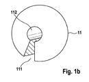
- Such an inventive embodiment is, for example, in FIG. 1b . 2c . 3b . 4c . 4e . 5b and 5c shown.
- all other attachment measures of the stents according to the invention which are considered by those skilled in the art due to its expertise, are hereby also claimed.
- FIG. 4b This includes in particular embodiments in a hook shape, which exemplifies in FIG. 4b being represented.
- drug depots according to the invention can be adhered to an implantable body, preferably stents, which can be used, for example, in US Pat FIGS. 7a to 7d is pictured.
- suitable active substance depots preferably have concave locations which conform to the struts of the struts of an implantable stent.
- Suitable adhesives are preferably superglue from the class of acrylates, fibrin glue, fats and polysaccharides.
- drug depots which completely enclose a strut or a strut of a stent and are connected to one another in a suitable manner such that the depot of active substance can not roll off the strut or the strut (see FIGS. 8a to 8e ).
- Per implantable body preferably stent, one or more drug depots, which may differ in the drug concentration and / or in the drug type, can be clipped.
- the drug depots are usually designed so that they interfere with implantation of the body in a vascular system as little as possible and are therefore preferably in existing interstices of the implantable body, preferably the stent, housed or they cover the body, preferably the stent, as a thin, low hoses.
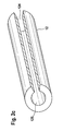
- an active substance depot produced according to the invention is characterized in that it is in the form of a tube (see, by way of example Figures 2c and 4c ), Film form (see, by way of example FIG. 5b ), Preform (see example Figures 1b . 3b . 4b . 4e and 5c ) or as (relatively) stiff nets.
- hose designates a round body which is round or oval in cross-section and optionally open on two sides.
- preform describes a negative form of a position of the implant, to which it is attached later.
- This "preform” may optionally be flexible or stiff.
- an active substance depot produced in accordance with the invention is used in the form of a tube, it is preferably produced by means of a pure extrusion method, tubular blowing method or deep-drawing process. In rare cases, but also via joining or adhesive technology. Under joining technique, in the case of the tube, shrinkage or "fitted" assembly by e.g. Plugging in to understand.
- the hose represents only an intermediate step in the production of the medicament carrier, it can also be slit, lined on the inside with a bonding agent and finally with the stent, by e.g. Unroll, be connected. Alternatively, the stent itself may be provided with the primer and then replaced by e.g. Unrolling be connected to the slotted tube.
- method step c) of the method according to the invention additionally comprises bringing the depot of active substance in tube form to the length of a stent and / or strut of the stent and the tube shape along the axis is slit and the thus processed hose is formed so that it represents a clip which is mechanically connected to the webs and / or struts of the stent by means of force and / or adhesive insert, preferably form-fitting.
- an active substance depot produced according to the invention in film form is used, it is preferably produced by means of an extrusion process, casting process or rolling process. Sometimes films can also be drawn from a melt or solution.
- the process according to the invention for preparing the active substance depot in process step c) additionally comprises processing the drug depot in film form in such a way that the film form i) is joined to the surface of the abluminal surface of the body, preferably of the stent or ii) to a part thereof ,
- a film can therefore be applied around the entire stent or around a strut or strut of a stent and especially as in FIG. 5a attached to the struts at the ends of an implantable stent. If a film is applied to the ends of an implant, preferably a stent, the film should be such that it does not enter the lumen and thus impair the unobstructed blood flow.
- the film form i) or ii) of the active substance depot used according to the invention is preferably characterized in that the film shape can be perforated according to the geometry of the abluminal surface of the stent Foil material corresponds to the areas of the material of the stent.
- the films described could also be perforated, for example, to allow the blood flow in the side branches of blood vessels.
- Inventive drug depots in film form can also by means of suitable means, preferably C-shaped gripper hooks, etc., with the endovascular implantable body, preferably positively connected.
- suitable means preferably C-shaped gripper hooks, etc.
- Such a preferred embodiment of the invention is particularly in FIGS. 5a and 5b shown.
- the active substance depot according to the invention is produced as a preform, it is preferably characterized in that it is a hollow body which is produced, for example, by means of a hollow-body blowing method or injection molding method, wherein the preform is the negative of a position of the implant, preferably a stent, on which it is to be applied , represents.
- a preform is produced according to a method according to the invention for producing the active substance depot, it is preferably designed such that it adheres to the body, preferably a stent (US Pat. Fig. 7a to 7d ), clicked together ( Fig. 8a to 8e ) or by welding together the upper and lower sides can be applied and thus with the body, preferably stent, preferably mechanically positively connectable.
- a stent US Pat. Fig. 7a to 7d
- clicked together Fig. 8a to 8e
- an active ingredient depot is used as a preform for the connection with an endovascular implantable stent, it is preferably processed in accordance with the invention such that the preform is slit along the axis or is already cast with a slot and this preform is designed such that it represents a clip which can be mechanically connected to the stent by means of a force and / or adhesive insert, preferably with a positive fit ( Fig. 4e ).
- an active substance depot is used as a preform for connection to struts or struts of an endovascular implantable stent
- the preform is processed according to the method according to the invention so that it is brought to the length of the webs or struts of the stent, slotted along the axis or already cast with slot present and this preform is designed so that it represents a clip which is mechanically connected to the webs or struts of the stent by means of force and / or adhesive insert, preferably form-fitting.
- FIGS. 1a, 1b, 3b, 4c, 4e and 5c Such an inventive embodiment is exemplified in FIGS. 1a, 1b, 3b, 4c, 4e and 5c ,
- the preform may consist of two parts, which are then welded around the strut or strut.
- Cytostatics include, in particular, DNA-alkylating substances, in particular nitrogen-nitrogen compounds and nitrosourea compounds; Platinum compounds; hydroxyurea compounds; Antimetabolites, preferably folic acid antagonists, purine analogs and pyrimidine analogs; Microtubule inhibitors, preferably winker alkaloids, taxanes, preferably paclitaxel and dozetaxel; Topoisomerase inhibitors; Antibiotics, preferably anthracyclines, more preferably danorobizine, doxorubicin, epirubicin and idarubicin, anactinomycins, especially dactinomycin, methoxanthrone, asarcine and ansarkrin, mitomycin C and bleomycin; as well as various cytostatics from the group asparaginase, metefusin and imatinib; Hormones, preferably glucocorticoids, in particular prednisone, sex hormones, particularly preferably
- an endovascularly implantable body preferably a stent, more preferably a degradable stent
- the method preferably additionally comprises that the or one of the bodies from step a) of the invention Process before connection to the drug depot in step c) is coated wholly or partially with one or more adjuvants, wherein the aid or the auxiliaries are designed so that they enhance the mechanical connection of the drug depot or with the body or bodies.
- adhesives are preferably used as an aid, preferably pure plastic solvents, superglue from the class of acrylates, fibrin glue, fats and polysaccharides.
- the manufacturing method according to the invention for the production of the drug-loaded endovascular implantable body preferably a (degradable) stent, a tubular form used as a drug depot, it is preferably designed so that it corresponds to the length of a web or strut of the stent corresponds, is slotted along the axis and thus represents a clip which is mechanically connected in method step c) by means of force and / or adhesive insert with the web or strut of the stent, preferably form-fitting.
- an active substance depot produced according to the invention in film form is used, preferably film i) or ii) is used, then the endovascular implantable body, preferably a (degradable) stent, in step c) with the abluminal surface on the film i) or ii) unrolled and thus by means of force and / or adhesive, preferably form-fitting, mechanically connected.
- the manufacturing method according to the invention is characterized in that the preform is designed in such a way that it is glued, clipped or welded together in step c) onto the implantable body, preferably stent, and thus mechanically, preferably with a positive fit is connected.
- the preform can also be attached to the implantable body by shrinking with gentle heat supply, so that the active ingredient (s) are not damaged.
- a method according to the invention for producing the drug-loaded endovascular implantable body is characterized in that in a further step, the preform is machined so that it is slit along the axis or already cast slot and this preform represents a clip in step c ) is mechanically connected to the body, preferably stent, by means of force and / or adhesive, preferably positive.
- the preform is brought to the length of a web or a strut of the stent, slit along the axis or already cast with slot, so that this preform is a clip in step c) with the web or strut of the stent by means of force and / or adhesive insert, preferably positively, mechanically connected.
- the drug-loaded, endovascular implantable body represents a stent which can be produced by a method according to the invention, it is preferably a degradable endovascular implantable stent, more preferably a degradable metal stent.
- the preferred embodiments described herein for the inventive manufacturing method are also applicable to the present inventive implantable body, preferably (degradable) stent.
- the preferred embodiments thereof are those which are implantable on the drug depot or the endovascular Obtain body, further explained by the preferred embodiments described in relation to the manufacturing method according to the invention.
- Preferred embodiments for the inventive use of one or more drug depots for producing an active ingredient-loaded implantable body or for the method according to the invention for the prophylaxis or treatment of a stenosis, aneurism or tumor tissue can be achieved by incorporating one or more of the aforementioned preferred embodiments into the body become.
- the active substance (s) are specially applied for the particular therapy.
- a high concentration of active ingredient (s) is preferably used for the prophylaxis or therapy of a tumor tissue.
- drug depot forms are preferred for an embodiment of the invention in this regard, which may contain a high concentration of active ingredient. Examples of suitable drug depots in FIGS. 3a . 3b . 5a . 5b and 5c shown.
- a drug-loaded stent preparable according to the invention is implanted in a blood vessel which carries blood to the tumor, preferably near the tumor tissue.
- the figures show, by way of example, sections of the abluminal surface of stent geometries of a stent basic body or the active substance depots according to the invention in a perspective view or in cross section.
- the present invention is not limited to the stent geometries shown here or to the arrangement of the drug depots shown.
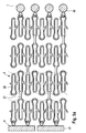
- FIG. 1a shows an abluminal section of a stent geometry 2, which in US 6,896,695 is described, together with a plurality of, preferably form-fitting, angeklippten drug depots 1 in the form of slotted beads 11, wherein the drug depot beads 11 according to the invention have a cavity and slotted 111 are that the beads in particular to the longitudinal connectors (struts) 21 or alternatively to the straight Regions of the stent struts 22 (the latter embodiment not shown), preferably form-fitting, can be clipped (see also FIG. 1b ).
- Such an embodiment according to the invention is preferred for one or more active substances which have a good distribution in the vascular tissue after release of the active substance (s).
- a further advantage is that, due to the high proportion of stent body 2 that is not loaded with active substance, improved growth with endothelial cells (EC; endothelialization) compared to conventionally completely coated stents of the prior art can be made possible. This improved endothelialization of the stent 2 can also reduce the risk of thrombosis associated with the implantation of an endovascular implantable body.
- EC endothelialization
- FIG. 1b shows a view of drug depot beads 11 according to the invention with a slot 111 and a cavity 112 which is designed so that it can be clipped to a Strut 21 or web 22 of a stent 2, preferably a form-fitting.
- active substance depot beads 11 may comprise one or more active substances according to the invention.
- the drug depot beads 11 used may each comprise different concentrations of one or more drugs.
- Inventive drug depots in the form of beads 11 are preferably prepared by casting, film and joining methods.
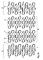
- FIG. 2a shows an abluminal section of a stent geometry 2, which in US 6,896,695 with a plurality of clipped drug depots 1 in tube form 12, wherein the tubes 12 are configured to be slotted along the longitudinal side 126 and have a cavity 127, in particular to the struts 21 or alternatively to the straight regions the stent struts 22 of a stent 2, preferably form-fitting, to be clipped (see also Figure 2c ).
- Such an active ingredient loading according to the invention is preferably of interest for a nationwide loading with two, three or more drug depots (121, 122 and 123). In this way, a multiple-drug release, in particular a dual-drug release (release of 2 drugs) or a triple drug release (release of 3 drugs) are made possible.
- Such a configuration is furthermore particularly preferred for those drug depots whose polymer can not be connected to the basic body of the stent or the implantable body in the absence of suitable solvent or polymer adhesion to the stent material used in accordance with conventional coating methods.
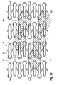
- FIG. 2b shows a modification FIG. 2a
- the regions 23 of the stent have a lower loading with the drug depots 12, ie, fewer drug depots 12 per surface of the stent 2, compared to the regions 24 of the stent.
- the agent depots 12 are preferably clipped onto the web 22 or strut 21 of a stent 2 in a form-fitting manner.
- Figure 2c shows a view of the slotted drug depots according to the invention in tube form 12, a slot 124 and a cavity 125 which is designed so that it can be clipped to a Strut 21 or web 22 of a stent 2, preferably a form-fitting.
- An agent depot 12 may typically contain one or more agents. Agent depots 121, 122 and 123 differ in that they each comprise different active ingredients.
- Inventive drug depots in tube form 12, 121, 122 and 123 are preferably prepared by means of extrusion process, tube blowing and deep drawing process. In rare cases, joining or gluing techniques are used.
- FIG. 3a shows a plan view of a abluminal section of a stent geometry 2 with a plurality of slotted substance depots 13 in preform, which are on Struts 21 or webs 22 of a stent 2, preferably clipped form-fitting.
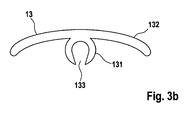
- the agent depot 13 according to the invention is designed such that it comprises a C-shaped gripper 131 with slot 133, which can be clipped onto a strut 21 or web 22 of a stent 2, preferably with a positive fit, and a matrix 132.
- Active substance depots 13 according to the invention comprise one or more active substances and are preferably produced by means of casting methods, if appropriate combined with milling or plugging together or by means of a suitable joining method (heat bonding, gluing) or injection molding.
- agent depot 13 By means of agent depot 13 according to FIG. 3a or 3b a high concentration of active ingredient in the drug depot 13 is made possible.
- the active ingredient concentration is preferably localized in the matrix material 132 of the drug depot 13, which is arranged on the abluminal surface of the implantable body, preferably stents. This makes it possible that little to no drug is released from the drug depot 13 into the vessel lumen of an implanted stent 2 and thus an endothelialization of the stent 2 is not delayed or prevented. Accordingly, the risk of restenosis or thrombosis formation is reduced according to the invention.
- FIG. 4a shows a plan view of a abluminal section of a stent geometry 2 with multiple drug depots 14 and 15, which are clipped on the abluminal surface of Struts.
- This embodiment according to the invention is comparable to the embodiment according to the invention in FIG. 3a , with the difference that the drug depots 14 and 15, in contrast to the drug depot 13 are not freely rotatably angeklippt around the struts 21 and webs 22 of the stent 2.
- FIG. 4a shows a plan view of a abluminal section of a stent geometry 2 with multiple drug depots 14 and 15, which are clipped on the abluminal surface of Struts.
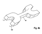
- FIG. 4b shows a perspective view of an inventive drug depot 14.
- This comprises means 141 which are formed so that they are with a Strut 21 or a web 22 of a stent 2, preferably form-fitting, mechanically connectable.
- the means 141 represents a hook shape.
- agents according to the invention can be produced from the same material as the active agent depot.
- An active substance depot 14 according to the invention is furthermore preferably designed such that it at least partially covers the abluminal surface of a strut 21 and / or web 22 of the stent 2 in the clip-on state.
- little to no polymer, preferably no active ingredient-containing polymer of the drug depot 14 or 15, is present on the luminal surface of the stent 2.
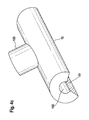
- Figure 4c shows a perspective view of an inventive drug depot 15.
- Agent depot 15 is configured in tube or preform, wherein it has a slot 151 and a cavity 152 which is configured so that it to a Strut 21 or web 22, preferably form-fitting clipped can be.
- the agent depot 15 comprises material that is designed such that, when clipped on, it covers the abluminal surface of a strut 21 or web 22.
- the slit 151 is so broad that the active substance depot 15 has little or no matrix material of the active agent depot 15 in the state clipped onto the strut 21 or web 22 of the stent 2 on the luminal side.
- FIG. 4d shows a plan view of a abluminal section of a stent geometry 2 with multiple drug depots 16.
- the drug depots are designed so that they clipped both luminal and the corresponding abluminal regions of one or more webs 22 and / or struts 21 of a stent 2, preferably positive fit , cover.
- Figure 4e shows a perspective view of an agent depot 16 that is designed so that it covers both lumbar as well as the corresponding abluminal areas of one or more webs 22 and / or struts 21 of a stent 2, preferably positive fit, when clipped.
- the active substance depot 16 has an upper region 161, which preferably covers the abluminal surface of a stent 2, and a lower region 162, which preferably covers the luminal surface of a stent 2.
- an agent depot 16 according to the invention has a slot 163, which allows the depot 16 to be attached to one or more webs 22 and Struts 21 can be clipped.
- an active substance depot according to the invention comprises cavities 164 which are formed such that in the clipped state, preferably in a form-fitting manner, the webs 22 and struts 21 of a stent 2 comprise.
- cavities 164 which are formed such that in the clipped state, preferably in a form-fitting manner, the webs 22 and struts 21 of a stent 2 comprise.
- only one or more active substances are incorporated in the area 161 of the active substance depot. This has the advantage that the diminished delivery of the agent (s) to the vessel lumen does not reduce or prevent the endothelialization of the stent 2.
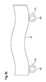
- FIG. 5a 2 shows a plan view of an abluminal section of a stent geometry 2 with terminal, preferably form-fitting, clipped-on active substance depots in the form of a band 17 or of a body 18.
- DES drug-eluting stent
- the stent is not used for its support structure, but serves as an anchorage for the drug depots 17 and 18 according to the invention.
- a stent loaded in this manner according to the invention is preferably implanted in a blood vessel which carries blood to the tumor tissue, preferably close to the stent tumor tissue. This makes it possible that the highest possible concentration of active ingredient used reaches the tumor tissue.
- FIG. 5b shows a perspective view of an inventive drug depot in band form 17.
- the band 17 also has means 171, which allow the band 17 to a endovascular implantable body, preferably stent, can be mechanically connected.
- a means 171 in the form of a C-shaped gripper is used which has a slot 171.
- the C-shaped gripper 171 comprises, preferably in a form-fitting manner, a web 22 or a strut 21 of a stent 2.
- This active substance depot 17 can comprise one or more active substances.
- FIG. 5c shows a cross-section of an active substance depot in the form of a body 18.
- the body 18 also has means 181, which enable the body 18 to be mechanically connected to an endovascular implantable body, preferably a stent.
- a means 181 in the form of a C-shaped gripper is used which has a slot 181.
- the C-shaped gripper 181, preferably in a form-fitting manner comprises a web 22 or a strut 21 of a stent 2
- Agent depot 18 may include one or more agents.
- the C-shaped grippers can be made, for example, by injection molding, reservoir, by joining (gluing, melting) or by any other suitable method described above.
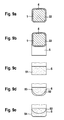
- FIG. 6a shows a plan view of a abluminal section of a stent geometry 2 with terminally attached drug depots 19 in cap form, which are shrunk onto the webs 22 of a stent 2, preferably a positive fit.
- the active substance depots 19 are shrunk onto the round end regions of the stent 2 so as not to damage the active substance or substances.
- FIG. 6b For example, a perspective view of an agent depot 19 with the surface 191 toward the vessel lumen or vascular tissue and the inner surface 192 toward the ridges 22 is shown.
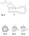
- Figure 7a shows a schematic abluminal plan view of a section of a stent geometry 2 with stent struts 22 and a drug depot 1 in film form, which is preferably adhered to the stent strut 22 by means of superglue from the class acrylates, fibrin glue, fats or polysaccharides.
- the active substance depot 1 can have concave locations, and thus be glued to the stent struts 22 in a form-fitting manner.
- FIG. 7b shows a cross section of a stent strut 22 with a drug depot 1 in foil form.
- FIG. 7c shows a cross-section of a stent strut 22 with drug depot 1, wherein the drug depot is disposed on the abluminal surface of the stent strut 22 and accordingly only a small proportion of the active substance (s) contained in the drug depot 1 is delivered to the vessel lumen.
- This is advantageous because it promotes endothelialization of the stent and reduces the side effects of the stent as a foreign body.
- FIG. 7d also shows a cross-section of a stent strut 22 with drug depot 1, which is also arranged abluminally on the stent strut. Again, only small amounts of active ingredient are released from the drug depot 1 to the vessel lumen.
- drug depot 1 also arranged abluminally on the stent strut.
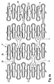
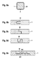
- FIG. 8a shows a cross section of a stent strut 22 with a stent strut surrounded agent depot 1 and connection mechanism 30th
- connection mechanism 31 of the drug depot 1 is shown enlarged.
- connection mechanism 31 is at the one end of the drug depot to a notch, which may optionally be introduced by milling in the drug depot and at the opposite second end of the drug depot to a protuberance, which is suitable to be inserted into the notch suitable , And so to effect a firm connection of the two ends of the drug depot.
- connection mechanism 32 of the drug depot 1 is shown enlarged.
- the connection mechanism 32 is an L-shaped connection mechanism, with the opposite ends of the drug depots each having mirror-inverted L-shaped ends which can be mated with one another to effect a firm connection of the ends of the drug reservoir 1.
- connection mechanism 33 of the drug depot 1 is shown enlarged.
- the connecting mechanism 33 is characterized in that the two opposite ends of the active substance depot 1 are each in the form of a hook and are hooked into one another, thus effecting a firm connection of the ends of the active substance depot 1.
- connection mechanism 34 of the drug depot 1 is shown enlarged.
- the connection mechanism 34 corresponds in principle to the connection mechanism in L-shape, as already in FIG. 8c
- the connecting mechanism 34 differs in that the superimposed surface 341 has protuberances and the surface 342 corresponding notches and thus cause a firm connection of the ends of the drug depot 1.
- FIG. 9a shows a cross-section of a stent strut 22 with agent depot 1, which is arranged overlapping in the area 4.
- This type of compound can either via the residual stress of the drug depot 1 or via a suitable adhesive in position 4 are attached.
- Preferred adhesives include superglue from the class of acrylates, fibrin glue, fats and polysaccharides.
- FIG. 9b shows a cross section of a stent strut 22 with agent depot 1, which overlaps in the region 4 and another drug reservoir 5, which is preferably arranged abluminally.
- the active substance depot 1 preferably has no active ingredient.
- the drug depot is brought into shape either by internal stress or by additional bonding in the area 4.
- the reservoir 5 of the drug depot 1 one or more active ingredients, preferably antiproliferative agents.
- FIG. 9c schematically is a cross section of the drug reservoir 5 of the drug depot 1, as in FIG. 9b , now shown as drug reservoir 51 with a homogeneous drug distribution of one or more drugs.
- FIG. 9d is the drug reservoir 5 of the drug depot 1 according to FIG. 9b shown as a reservoir 52, wherein the active ingredient is homogeneously distributed and over this layer, a top coat 53 is coated, which influences the release of the active substance or in the reservoir 52.
- FIG. 9e becomes a drug reservoir 5 of an agent depot 1 according to FIG. 9b shown in a preferred embodiment.
- the reservoir 52 contains a homogeneous distribution of an active substance and the reservoir 54 a homogeneous distribution of another active substance. This enables a dual-drug application.
Abstract
Description
Die vorliegende Erfindung betrifft ein Verfahren zur Herstellung eines Wirkstoffdepots, ein Verfahren zur Herstellung eines wirkstoffbeschichteten, endovaskulären implantierbaren Körpers, einen wirkstoffbeladenen, endovaskulären implantierbaren Körper, herstellbar nach einem erfindungsgemäßen Verfahren sowie ein Kit umfassend oder bestehend aus einem oder mehreren Wirkstoffdepots, herstellbar nach einem erfindungsgemäßen Verfahren und ein oder mehrere endovaskuläre implantierbare Körper.The present invention relates to a process for the preparation of an active substance depot, a process for the production of an active substance-coated, endovascular implantable body, an active substance-loaded, endovascular implantable body, which can be produced by a method according to the invention and a kit comprising or consisting of one or more active substance depots, which can be produced according to the invention Method and one or more endovascular implantable body.
Endovaskuläre implantierbare Körper werden in der Medizintechnik unter anderem dafür verwendet, Gefäßstrukturen zu unterstützen. Insbesondere um koronare Herzerkrankungen, insbesondere akute Myokardinfarkte, zu behandeln, werden endovaskuläre Prothesen bzw. Implantate, insbesondere endovaskuläre Stents, verwendet. Solche Körper sind ebenfalls bekannt für die Behandlung von Aneurismen. Stents weisen grundsätzlich eine Tragstruktur auf, die geeignet ist, die Wand eines Gefäßes in geeigneter Weise abzustützen, und so das Gefäß zu weiten bzw. ein Aneurisma zu überbrücken.Endovascular implantable bodies are used in medical technology, among other things, to support vascular structures. In particular, in order to treat coronary heart disease, in particular acute myocardial infarction, endovascular prostheses or implants, in particular endovascular stents, are used. Such bodies are also known for the treatment of aneurysms. In principle, stents have a support structure which is suitable for supporting the wall of a vessel in a suitable manner, thus bridging the vessel or bridging an aneurysm.
Dazu werden Stents in einem komprimierten Zustand in das Gefäß eingeführt und dann an dem zu behandelnden Ort aufgeweitet und gegen die Gefäßwand gedrückt. Dieses Aufweiten kann beispielsweise mit Hilfe eines Ballonkatheters erfolgen. Alternativ sind auch selbstexpandierende Stents bekannt. Diese sind beispielsweise aus einem superelastischen Metall, wie Nitinol, aufgebaut.For this purpose, stents are introduced into the vessel in a compressed state and then expanded at the location to be treated and pressed against the vessel wall. This expansion can be done for example by means of a balloon catheter. Alternatively, self-expanding stents are also known. These are for example made of a superelastic metal, such as nitinol.
Mit dem Aufweiten des Blutgefäßes entstehen allerdings kleinste Verletzungen und Einrisse (Dissektionen) in der Gefäßwand, die zwar häufig problemlos verheilen, jedoch in etwa einem Drittel der Fälle durch das ausgelöste Zellwachstum zu Wucherungen (Proliferation) und letztendlich zu einer erneuten Gefäßverengung (Restenose) führen können. Die Aufweitung des Gefäßes durch endovaskuläre Stents beseitigt zudem nicht die Ursachen der zugrunde liegenden Stenose, also die molekularpathologischen Veränderungen in der Gefäßwand. Eine Ursache der Restenose ist des Weiteren die übermäßige Elastizität des durch den Stent gedehnten Blutgefäßes. Üblicherweise zieht sich nach Entfernen des Ballons das gedehnte Blutgefäß übermäßig zusammen, so dass der Gefäßquerschnitt gegenüber dem nicht gedehnten Areal des Blutgefäßes verringert wird (Obstruktion, so genanntes negatives Remodelling). Letzterer Effekt kann durch die Platzierung eines endovaskulären Implantats, in der Regel eines Stents, vermieden werden.With the dilation of the blood vessel, however, smallest injuries and tears (dissections) in the vessel wall, which often heal easily, but in about one third of cases caused by the induced cell growth to growth (proliferation) and ultimately to a renewed vasoconstriction (restenosis) can. The widening of the vessel by endovascular stents also does not eliminate the causes of the underlying stenosis, that is, the molecular pathological changes in the vessel wall. Another cause of restenosis is excessive Elasticity of the blood vessel stretched through the stent. Usually, after removal of the balloon, the dilated blood vessel contracts excessively, so that the vessel cross-section is reduced compared to the unstretched area of the blood vessel (obstruction, so-called negative remodeling). The latter effect can be avoided by placing an endovascular implant, usually a stent.
Zwar hat die Einführung der Stents in der interventionellen Therapie der stabilen und instabilen Angina pectoris bei koronaren Herzerkrankungen zu einer deutlichen Reduktion der Rate an Restenosen und damit zu besseren Langzeitresultaten geführt, was primär dem Lumengewinn zuzuschreiben ist, allerdings können die auftretenden kleinsten Verletzungen, welche die Proliferation induzieren können, wiederum eine Restenose auslösen. Zudem kann die Anwesenheit eines derartigen Fremdkörpers in dem Gefäßsystem eine Kaskade von zellulären molekularen Prozessen initiieren, die zu einem allmählichen Zuwachsen des Gefäßes (insbesondere auch Thrombenbildung) in dem Bereich, in dem das Implantat, insbesondere der Stent implantiert ist, führen können.Although the introduction of stents in the interventional therapy of stable and unstable angina pectoris in coronary heart disease has led to a significant reduction in the rate of restenosis and thus to better long-term results, which is primarily attributable to the lumen gain, but the smallest injuries that occur Induce proliferation, in turn trigger restenosis. In addition, the presence of such a foreign body in the vasculature may initiate a cascade of cellular molecular processes that may result in gradual growth of the vessel (particularly thrombus formation) in the region where the implant, particularly the stent, is implanted.
Seit einigen Jahren versucht man deshalb die Restenosegefahr bei der Implantation von Stents durch die Verwendung von mit Wirkstoff beschichteten Stents weiter zu vermindern (Local Drug Delivery (LDD); Drug Eluting Stents (DES)). Aber auch in nicht koronarbezogenen Erkrankungen kommen Wirkstoffträger zum Einsatz, die in Gefäße implantiert werden (Drug Reservoirs für nicht koronare Anwendungen (Krebstherapie etc.)).For several years, attempts have therefore been made to further reduce the risk of restenosis in the implantation of stents through the use of drug-coated stents (Local Drug Delivery (LDD); Drug Eluting Stents (DES)). But also in non-coronary diseases are drug carriers used, which are implanted in vessels (drug reservoirs for non-coronary applications (cancer therapy, etc.)).
Die Träger derartiger wirkstoffhaltiger Beschichtungssysteme bestehen regelmäßig aus einem biokompatiblen Material, welches entweder natürlichen Ursprungs ist oder auf synthetischem Wege gewonnen werden kann. Zur Aufbringung der Beschichtungssysteme auf den Stent sind zahlreiche Verfahren entwickelt worden, wie beispielsweise Rotationszerstäubungsverfahren, Tauchverfahren und Sprühverfahren. Das Beschichtungssystem bedeckt zumindest bereichsweise die Oberfläche des Stents, wobei eine Freisetzung der pharmakologischen Wirkstoffe im menschlichen bzw. tierischen Körper durch allmähliche Degradation des Trägers und/oder Diffusion in das umgebende Gewebe erfolgt.The carriers of such drug-containing coating systems are usually made of a biocompatible material, which is either of natural origin or can be obtained by synthetic means. Numerous methods have been developed for applying the coating systems to the stent, such as rotary atomization methods, dipping methods and spraying methods. The coating system at least partially covers the surface of the stent, with a release of the pharmacologically active substances in the human or animal body by gradual degradation of the carrier and / or diffusion into the surrounding tissue.
Unter einer wirkstoffhaltigen Beschichtung von endovaskulären Stents ist üblicherweise eine flächige Beschichtung zu verstehen. Zum Teil können aber auch die Beschichtungen darin bestehen, dass die auftretenden Löcher bzw. Kavitäten der Stentgeometrie gefüllt sind oder einseitige oder punktförmige Beschichtungen auf der Tragstruktur der Stents bestehen. Solche Beschichtungen sind allerdings technologisch sehr anspruchsvoll als auch zeit- sowie kostenintensiv.A drug-containing coating of endovascular stents is usually to be understood as meaning a planar coating. In some cases, however, the coatings can also consist in that the occurring holes or cavities of the stent geometry are filled or one-sided or punctiform coatings on the support structure of the stents exist. However, such coatings are technologically very demanding as well as time-consuming and cost-intensive.
Man hat nun festgestellt, dass jedoch nicht alle Beschichtungsmaterialien mit/und ohne inkorporierte(m) Wirkstoff(en) direkt auf den implantierbaren Körper, gemäß der üblicherweise verwendeten Verfahren, beschichtet werden können.It has now been found, however, that not all coating materials with / and without incorporated drug (s) can be coated directly onto the implantable body according to commonly used procedures.
Im Allgemeinen ist bei den meisten Beschichtungsverfahren ein vorheriges Lösen der Polymermatrix, vor der Beschichtung, notwendig. Um jedoch die notwendige Lösemittelfreiheit des "Drug Eluting" Implantates sicher zu stellen, müssen teilweise aufwendige Verfahrensschritte zur Extraktion desselben Lösungsmittels, die dem Beschichtungsschritt nachgeschaltet sind, vorgenommen werden.In general, most coating processes require prior dissolution of the polymer matrix prior to coating. However, in order to ensure the necessary freedom from solvents of the "drug eluting" implant, sometimes complex process steps for the extraction of the same solvent, which are connected downstream of the coating step, must be carried out.
Aufgrund unterschiedlicher physiko-chemischer Eigenschaften von Substratoberfläche und Beschichtungsmaterial (hydrophobe, hydrophile Eigenschaften) können ggf. die gewünschten Oberflächeneigenschaften des herzustellenden Implantates nicht erzielt werden. Um diese Eigenschaften dennoch zu erreichen, sind zum Teil aufwändige Verfahrensschritte zur Vorbehandlung der jeweiligen Oberfläche notwendig, was zu einem zusätzlichen Fertigungsschritt auch ggf. Folgen für die Biokompatibilität haben könnte.Due to different physicochemical properties of the substrate surface and coating material (hydrophobic, hydrophilic properties), the desired surface properties of the implant to be produced may possibly not be achieved. In order to achieve these properties, however, sometimes complex process steps for the pretreatment of the respective surface are necessary, which could possibly have consequences for the biocompatibility to an additional manufacturing step.
Auch können wirkstoffbeladene Polymerschichten bei hoher Wirkstoffbeladung insbesondere zu mechanischen Problemen der Schicht bei der Dilatation des Stents führen.In addition, active ingredient-loaded polymer layers can lead to mechanical problems of the layer during dilatation of the stent with high drug loading.
Bei den bekannten Beschichtungsformen von Stents ist man üblicherweise auf eine Wirkstoff-Dosis-Kombination beschränkt, da es sehr schwierig ist, Beschichtungen zu realisieren, welche unterschiedliche Elutionsraten eines Wirkstoffes oder Elutionen mehrerer Wirkstoffe (multiple-drug-release, insbesondere dual-drug-release, tripple-drug-release etc.), insbesondere in unterschiedlichen Elutionsraten, besitzen.In the known coating forms of stents is usually limited to a drug-dose combination, since it is very difficult to realize coatings which different elution rates of an active ingredient or elutions of several drugs (multiple drug release, especially dual-drug release , tripple-drug-release etc.), especially in different elution rates.
Eine Aufgabe der vorliegenden Erfindung besteht deshalb darin, ein Wirkstoffdepot bereitzustellen, das an einen endovaskulär implantierbaren Körper, unabhängig von dessen Material, gebunden werden kann. Eine weitere Aufgabe der vorliegenden Erfindung besteht darin, dass ein endovaskulär implantierbarer Körper bereitgestellt wird, der ein oder mehrere Wirkstoffdepots mit ein oder mehreren Wirkstoffen umfasst, wobei der oder die Wirkstoffe gezielt in Bezug auf die Elutionszeit und -konzentration eingestellt werden können. Eine weitere Aufgabe besteht darin, unerwünschte Implantatnebenwirkungen, z.B. Erhöhung des Restenose- und/oder Thrombosebildungsrisikos zu vermindern.It is therefore an object of the present invention to provide a drug depot which can be bound to an endovascular implantable body, irrespective of its material. A further object of the present invention is to provide an endovascular implantable body comprising one or more drug depots with one or more active agents, wherein the or the active ingredients can be adjusted specifically with respect to the elution time and concentration. Another object is to reduce unwanted implant side effects, eg, increase the risk of restenosis and / or thrombosis.
Die erfindungsgemäßen Aufgaben werden gelöst durch ein Verfahren zur Herstellung eines Wirkstoffdepots, das zur mechanischen Verbindung mit einer Oberfläche eines endovaskulär implantierbaren Körpers ausgebildet ist, umfassend oder bestehend aus folgenden Schritten:
- a) Bereitstellung eines oder mehrerer Polymere,
- b) Bereitstellung eines oder mehrerer Wirkstoffe und
- c) Herstellung eines Wirkstoffdepots aus dem oder den Polymeren und dem oder den Wirkstoffen, wobei das Wirkstoffdepot so ausgebildet ist, dass es mittels Krafteinwirkung und/oder Klebstoffeinsatz mit der Oberfläche des Körpers mechanisch verbindbar ist.
- a) providing one or more polymers,
- b) providing one or more active substances and
- c) Production of an active substance depot from the polymer or polymers and the active substance (s), wherein the active substance depot is designed so that it can be mechanically connected to the surface of the body by means of force and / or adhesive application.
Ein weiterer Gegenstand der vorliegenden Erfindung betrifft ein Verfahren zur Herstellung eines wirkstoffbeschichteten endovaskulär implantierbaren Körpers, umfassend oder bestehend aus folgenden Schritten:
- a) Bereitstellung eines endovaskulär implantierbaren Körpers,
- b) Bereitstellung eines oder mehrerer unterschiedlicher Wirkstoffdepots, das oder die erfindungsgemäß herstellbar sind und
- c) mechanische Verbindung des oder eines der Wirkstoffdepots aus Schritt b) mit dem Körper aus Schritt a).
- a) providing an endovascular implantable body,
- b) providing one or more different drug depots that are or can be produced according to the invention and
- c) mechanical connection of the or one of the active substance depot from step b) with the body from step a).
Ein weiterer Gegenstand der vorliegenden Erfindung betrifft einen wirkstoffbeladenen, endovaskulär implantierbaren Körper, herstellbar nach einem erfindungsgemäßen Verfahren.Another object of the present invention relates to a drug-loaded, endovascular implantable body, produced by a method according to the invention.
Ein weiterer Gegenstand der vorliegenden Erfindung betrifft ein Kit umfassend oder bestehend aus:
- a) einem oder mehreren Wirkstoffdepots herstellbar nach einem erfindungsgemäßen Verfahren und
- b) einem oder mehreren endovaskulär implantierbaren Körpern.
- a) one or more drug depots produced by a method according to the invention and
- b) one or more endovascular implantable bodies.
Ein weiterer Gegenstand der vorliegenden Erfindung betrifft eine Verwendung eines oder mehrerer erfindungsgemäß hergestellter Wirkstoffdepots zur Herstellung eines wirkstoffbeladenen, endovaskulär implantierbaren Körpers, bevorzugt Stents, zu Prophylaxe oder Behandlung einer Stenose, eines Aneurisma oder eines Tumorgewebes in einem menschlichen oder tierischen Körper.Another object of the present invention relates to a use of one or more inventively prepared drug depots for producing a drug-loaded, endovascular implantable body, preferably stents, for the prophylaxis or treatment of a stenosis, aneurism or tumor tissue in a human or animal body.
Ein weiterer Gegenstand der vorliegenden Erfindung betrifft ein Verfahren zur Prophylaxe oder Behandlung einer Stenose, eines Aneurismas oder eines Tumorgewebes in einem menschlichen oder tierischen Körper umfassend oder bestehend aus folgenden Schritten:
- a) Bereitstellung eines endovaskulär implantierbaren Körpers, bevorzugt eines Stents,
- b) Bereitstellung eines oder mehrerer unterschiedlicher Wirkstoffdepots, das oder die erfindungsgemäß herstellbar sind,
- c) mechanische Verbindung des oder eines der Wirkstoffdepots aus Schritt b) mit dem Körper aus Schritt a) und
- d) Implantation des in Schritt c) hergestellten wirkstoffbeladenen Körpers in ein Blutgefäß, dass Blut zum Tumorgewebe führt.
- a) providing an endovascular implantable body, preferably a stent,
- b) providing one or more different depots of active substance which are or can be produced according to the invention,
- c) mechanical connection of the or one of the active substance depot from step b) with the body from step a) and
- d) implantation of the drug-loaded body produced in step c) into a blood vessel that leads blood to the tumor tissue.
Der vorliegenden Erfindung liegt die Erkenntnis zugrunde, dass ein erfindungsgemäßes Wirkstoffdepot, das separat von dem eigentlichen endovaskulär implantierbaren Körper gefertigt wird, zum einen in Bezug auf die Elutionscharakteristik des oder der inkorporierten Wirkstoffe technologisch einfacher optimiert werden kann und zum anderen unabhängig von dem verwendeten Material des implantierbaren Körpers, bevorzugt Stents, direkt mit diesem mechanisch verbunden werden kann. Somit können die erfindungsgemäß hergestellten Wirkstoffdepots, die mit den endovaskulär implantierbaren Körpern, vorzugsweise formschlüssig, mechanisch verbunden werden, in verbesserter Weise gegenüber dem Stand der Technik die gestellten Aufgaben lösen.The present invention is based on the finding that an active substance depot according to the invention, which is manufactured separately from the actual endovascular implantable body, can be technologically more easily optimized with respect to the elution characteristic of the incorporated active substance and, secondly, independently of the material used implantable body, preferably stents, can be mechanically connected directly to this. Thus, the active substance depots produced according to the invention, which are mechanically connected to the endovascular implantable bodies, preferably in a form-fitting manner, can solve the stated tasks in an improved manner compared with the prior art.
Vorteile eines erfindungsgemäß hergestellten implantierbaren Körpers mit erfindungsgemäßen Wirkstoffdepots bestehen demzufolge insbesondere darin, dass infolge der technologischen Trennung der Herstellung des implantierbaren Körpers und des Wirkstoffdepots eine direkte Wirkstoffbeladung des implantierbaren Körpers unabhängig von dem Material des implantierbaren Körpers ermöglicht wird.Advantages of an implantable body according to the invention with drug depots according to the invention therefore consist in particular in the fact that, as a result of the technological separation of the production of the implantable body and the drug depot, a direct drug loading of the implantable body is made possible independently of the material of the implantable body.
Ein weiterer Vorteil besteht darin, dass eine Beladung eines erfindungsgemäß hergestellten implantierbaren Körpers mit einem oder mehreren erfindungsgemäßen Wirkstoffdepots eine flexible, für die jeweilige Erkrankung maßgeschneiderte Wirkstofftherapie des implantierbaren Körpers ermöglicht. Eine Beladung eines Implantates mit einem oder mehreren erfindungsgemäßen Wirkstoffdepots ist technologisch einfach und dementsprechend können auch bereits vorhandene endovaskulär implantierbare Körper, seien sie wirkstoffbeschichtet oder nicht, mittels der erfindungsgemäßen Wirkstoffdepots (nach)beladen werden. Es können auch insbesondere in unterschiedlichen räumlichen Bereichen des endovaskulär implantierbaren Körpers, bevorzugt Stents, unterschiedlich viele Wirkstoffdepots beladen werden. Erfindungsgemäße Beispiele hierfür werden in
Ein weiterer Vorteil der erfindungsgemäßen Gegenstände besteht darin, dass nicht nur ein, sondern auch mehrere Wirkstoffe in dem Wirkstoffdepot insbesondere in (unterschiedlichen) Dosierungen vorliegen können, die - aufgrund der Limitierung durch beispielsweise die Schichtdicke - mit herkömmlichen Beschichtungen implantierbarer Körper nicht erreicht werden können.A further advantage of the objects according to the invention is that not only one but also several active substances can be present in the active substance depot, in particular in (different) dosages which - due to the limitation by, for example, the layer thickness - can not be achieved with conventional coatings of implantable bodies.
Insbesondere können hier zeitlich abgestufte Elutionskurven eines oder mehrerer Wirkstoffe in dem Wirkstoffdepot verwirklicht werden, beispielsweise eine kontinuierliche Erhöhung eines oder mehrerer Wirkstoffe, um den Körper, in den das Implantat mit Wirkstoffdepot implantiert wird, schrittweise an das oder die Wirkstoffe zu gewöhnen.In particular, time-graded elution curves of one or more active substances in the active substance depot can be realized here, for example a continuous increase of one or more active substances, in order gradually to accustom the body into which the implant with active substance depot is implanted to the active substance (s).
Bei üblichen wirkstoffbeschichteten Stents führen Beladungen von über 70 % Wirkstoff zu schlechten mechanischen Eigenschaften, insbesondere zu einem Aufbrechen der Wirkstoffschicht, sowie zu oftmals sehr kurzen Elutionskinetiken, die nicht immer erwünscht sind.In conventional drug-coated stents loadings of more than 70% active ingredient lead to poor mechanical properties, in particular to a break-up of the drug layer, as well as often very short elution kinetics, which are not always desirable.
Aufgrund der üblichen Schichtdicken von 50 bis 100 µm können Stentgeometrien entstehen, die ein Maß an Volumen des Gefäßlumens einnehmen, dass bei der Implantation des Stents (Deliverability) Probleme beim Passieren von Stenosen oder anderen Engstellen entstehen können (großes "Crossing Profile").Due to the usual layer thicknesses of 50 to 100 .mu.m, stent geometries can arise which take up a measure of the volume of the vessel lumen that during implantation Stent (Deliverability) problems may arise when passing through stenoses or other bottlenecks (large "Crossing Profile").
Im Gegensatz zu den üblichen Beschichtungsmethoden erlaubt die Verwendung erfindungsgemäßer Wirkstoffdepots, die an einen zu implantierenden Körper, bevorzugt Stent, angeklippt werden, zum einen die Ausnutzung des Platzes zwischen den Struts bzw. Stegen der zu implantierenden Stents oder das Anklippen der erfindungsgemäßen Wirkstoffdepots endständig an die zu implantierenden Körper, insbesondere Stents. Gerade bei dem endständigen Anklippen können Wirkstoffdepots verwendet werden, die eine hohe Konzentration an ein oder mehreren Wirkstoffen umfassen kann.In contrast to the usual coating methods, the use of active substance depots according to the invention, which are clipped to a body to be implanted, preferably a stent, allows firstly the utilization of the space between the struts or bars of the stents to be implanted or the clinging of the active substance depots according to the invention to be implanted body, in particular stents. Especially at the terminal clutches drug depots can be used, which may include a high concentration of one or more drugs.
Hohe Wirkstoffkonzentrationen sind insbesondere von Vorteil für Wirkstoffe aus der Gruppe der Limus-Wirkstoffe zur Behandlung der Restenose, insbesondere umfassend Sirolimus (Rapamycin), Zotarolimus (Abt-578), Tacrolimus (Fk506), Everolimus, Biolimus, insbesondere Biolimus A9, Paclitaxel (Taxol), Pimecrolimus, Lipidregulatoren, vorzugsweise Fibrate, Immunsuppressiva, Vasodilatatoren, vorzugsweise Sartane, Calciumkanalblocker, Calcineurininhibitoren, vorzugsweise Tacrolimus, Antiphlogistika, vorzugsweise Kortison und Diclofenac, Antiinflammatorika, vorzugsweise Imidazole, Antiallergika, Oligonucleotide, vorzugsweise Decoy-Oligodesoxynukleotid (dODN), Estrogene, vorzugsweise Genistein, Endothelbildner, vorzugsweise Fibrin, Steroide, Proteine/Peptide, Proliferationshemmer, Analgetika, Antirheumatika etc.High active ingredient concentrations are particularly advantageous for active ingredients from the group of limus drugs for the treatment of restenosis, in particular comprising sirolimus (rapamycin), zotarolimus (Abt-578), tacrolimus (Fk506), everolimus, Biolimus, especially Biolimus A9, paclitaxel (Taxol ), Pimecrolimus, lipid regulators, preferably fibrates, immunosuppressants, vasodilators, preferably sartans, calcium channel blockers, calcineurin inhibitors, preferably tacrolimus, antiphlogistics, preferably cortisone and diclofenac, anti-inflammatory agents, preferably imidazoles, antiallergics, oligonucleotides, preferably decoy oligodeoxynucleotide (dODN), estrogens, preferably Genistein, endothelium formers, preferably fibrin, steroids, proteins / peptides, proliferation inhibitors, analgesics, antirheumatics etc.
Höhere Wirkstoffkonzentrationen können ebenfalls für lokale Krebstherapien wünschenswert sein, so dass der oder die Wirkstoffe aus der Gruppe der Zytostatika, sofern das Implantat in ein dem Tumorgewebe zuführendes Gefäß, bevorzugt nahe dem Tumorgewebe, platziert wird, dort direkt in das Blutgefäß freigesetzt werden und in hoher Konzentration direkt mit dem Blutstrom dem Tumorgewebe zugeführt werden können. Es besteht hierbei die Möglichkeit, dass Nebenwirkungen, die mit den verwendeten Zytostatika assoziiert sind, verringert werden können.Higher active ingredient concentrations may also be desirable for local cancer therapies, so that the cytostatic agent (s), if the implant is placed in a tumor tissue delivery vessel, preferably near the tumor tissue, are released there directly into the blood vessel and into high blood levels Concentration can be supplied directly to the bloodstream to the tumor tissue. There is the possibility that side effects associated with the cytotoxic agents used may be reduced.
Erfindungsgemäße Ausgestaltungen für die vorstehend dargestellten bevorzugten Gegenstände werden beispielhaft in
Ein weiterer Vorteil der erfindungsgemäßen Gegenstände besteht darin, dass mehrere Wirkstoffdepots, welche jeweils unterschiedliche Wirkstoffe umfassen, mit einem endovaskulär implantierbaren Körper verbunden werden können, und so ein multiple-drug-release (Freisetzung mehrerer Wirkstoffe), insbesondere dual-drug-release (Freisetzung von zwei Wirkstoffen) oder ein tripel-drug-realease (Freisetzung von drei Wirkstoffen) erreicht wird, was durch eine herkömmliche Beschichtungsverfahren technologisch kaum oder nur mit erhöhtem Kosten- und/oder Zeitaufwand erreicht werden kann. Ein Beispiel für eine solche erfindungsgemäße Ausgestaltung wird in
Ein weiterer Vorteil besteht darin, dass Interaktionen zwischen den verwendeten Wirkstoffen und dem verwendeten Material für den implantierbaren Körper, bevorzugt Stent, verringert werden kann. Dies wird insbesondere dadurch bewerkstelligt, dass der endovaskulär implantierbare Körper, bevorzugt Stent, getrennt von dem erfindungsgemäßen Wirkstoffdepot hergestellt wird. Dies ist insbesondere von Nutzen bei Verwendung von degradierbaren (Grund-)körpern, wie z.B. degradierbaren Stents, insbesondere degradierbaren Metallstents, da hier eine direkte Wirkstoffbeschichtung mit dem (Grund)körper, aufgrund der Wechselwirkung mit dem Material des Körpers, mittels üblicher Verfahren nur schwierig bzw. teilweise überhaupt nicht möglich ist. Weiter bevorzugt ist die endständige Verknüpfung eines oder mehrerer Wirkstoffdepots an degradierbare Grundkörper, da der Abstand zwischen den sich wechselseitig beeinflussenden Materialien erhöht wird und damit die gegenseitige Beeinflussung verringert werden kann.Another advantage is that interactions between the active ingredients used and the material used for the implantable body, preferably stent, can be reduced. This is achieved in particular by producing the endovascular implantable body, preferably a stent, separately from the active substance depot according to the invention. This is particularly useful when using degradable (basic) bodies, such as e.g. degradable stents, especially degradable metal stents, since here a direct drug coating with the (basic) body, due to the interaction with the material of the body, by means of conventional methods only difficult or sometimes not at all possible. More preferably, the terminal connection of one or more drug depots to degradable body, since the distance between the mutually influencing materials is increased and thus the mutual influence can be reduced.
Die bevorzugten Ausgestaltungen der erfindungsgemäßen Gegenstände werden im Anschluss hieran sowie in den abhängigen Patentansprüchen beschrieben und sind des Weiteren der Figurenbeschreibung und den dazugehörigen Figuren zu entnehmen. Die bevorzugten Ausgestaltungen treffen auf alle Gegenstände der vorliegenden Erfindung auch insofern zu, als dass kein ausdrücklicher Verweis hierzu offenbart wird.The preferred embodiments of the objects according to the invention are described in connection thereto and in the dependent claims and are further to be taken from the description of the figures and the associated figures. The preferred embodiments are also applicable to all articles of the present invention insofar as no express reference is disclosed thereto.
Ein implantierbarer Körper im Sinne der vorliegenden Erfindung stellt zum einen üblicherweise einen degradierbaren oder nicht degradierbaren, kardiovaskulären oder peripheren Stent sowie einen Stent für andere Hohlräume, wie beispielsweise die Speiseröhre, den Gallengang, die Harnröhre, die Prostata oder die Luftröhre dar. Zum anderen stellen implantierbare Körper im Sinne der vorliegenden Erfindung local drug delivery Implantate dar, die endovaskulär im Blut oder anderen Hohlräumen implantiert werden. Im Weiteren können implantierbare Körper Neuroapplikationen darstellen, sowie subkutane Anwendungen zum kontinuierlichen Wirkstoffrelease (beispielsweise Hormonpräparate), aber auch Stimulationselektronen oder regional drug delivery Applikationen.For the purposes of the present invention, an implantable body usually represents a degradable or non-degradable cardiovascular or peripheral stent and a stent for other cavities, such as the esophagus, the bile duct, the urethra, the prostate or the trachea. On the other hand implantable body according to the present invention is local drug delivery implants that are implanted endovascularly in the blood or other cavities. In addition, implantable bodies can represent neuroapplications, as well as subcutaneous applications for continuous drug release (for example hormone preparations), but also stimulation electrons or regional drug delivery applications.
Im Sinne der vorliegenden Erfindung umfassen degradierbare Körper, bevorzugt Stents, als Werkstoffe degradierbares Metall oder degradierbares Polymer.For the purposes of the present invention, degradable bodies, preferably stents, comprise materials degradable as materials or degradable polymer.
Degradierbarer Metallwerkstoff:
- Vorzugsweise ist der degradierbare metallische Werkstoff eine biokorrodierbare Legierung, ausgewählt aus der Gruppe Magnesium, Eisen, Zink und Wolfram; insbesondere ist der degradierbare metallische Werkstoff eine Magnesiumlegierung.
- Preferably, the degradable metallic material is a biocorrodible alloy selected from the group consisting of magnesium, iron, zinc and tungsten; In particular, the degradable metallic material is a magnesium alloy.
Die Legierung, insbesondere umfassend Magnesium, Eisen, Zink und Wolfram, ist so in ihrer Zusammensetzung zu wählen, dass sie biokorrodierbar ist. Als biokorrodierbar im Sinne der vorliegenden Erfindung werden Legierungen bezeichnet, bei denen in physiologischer Umgebung ein Abbau stattfindet, der letztendlich dazu führt, dass der gesamte Stent oder der aus dem Werkstoff gebildete Teil des Stents seine mechanische Integrität verliert. Unter Legierung wird vorwiegend ein mechanisches Gefüge verstanden, deren Hauptkomponente Magnesium, Eisen, Zink oder Wolfram ist. Hauptkomponente ist die Legierungskomponente, deren Gewichtsanteil an der Legierung am höchsten ist. Ein Anteil der Hauptkomponente beträgt vorzugsweise mehr als 50 Gew.%, weiter bevorzugt mehr als 70 Gew.%.The alloy, in particular comprising magnesium, iron, zinc and tungsten, is to be selected in its composition so that it is biocorrodible. For the purposes of the present invention, biocorrodible materials are alloys in which degradation occurs in a physiological environment, which ultimately leads to the entire stent or the part of the stent formed from the material losing its mechanical integrity. Alloy is understood to mean predominantly a mechanical structure whose main component is magnesium, iron, zinc or tungsten. The main component is the alloy component whose weight fraction of the alloy is highest. A proportion of the main component is preferably more than 50% by weight, more preferably more than 70% by weight.
Ist der Werkstoff eine Magnesiumlegierung, so enthält diese vorzugsweise Yttrium und weitere Seltenerdmetalle, da sich eine derartige Legierung aufgrund ihrer physikochemischen Eigenschaften und hohen Biokompatibilitäten insbesondere auch seiner Abbauprodukte, auszeichnet.If the material is a magnesium alloy, it preferably contains yttrium and other rare earth metals, since such an alloy is distinguished by its physicochemical properties and high biocompatibilities, in particular its degradation products.
Besonders bevorzugt sind Legierungen der WE Reihe (WE 43 etc.) sowie Magnesiumlegierungen der Zusammensetzung Seltenerdmetalle 5,5 bis 9,9 Gew.%, davon Yttrium 0,0 bis 5,5 Gew.% und Rest umfassend Zirkon < 1 Gew.%, wobei Magnesium den auf 100 Gew.% fehlenden Anteil an den Legierungen einnimmt. Diese Magnesiumlegierungen bestätigten bereits experimentell und in ersten klinischen Versuchen ihre besondere Eignungen, d.h. sie zeigen eine hohe Biokompatibilität, günstige Verarbeitungseigenschaften, gute mechanische Kennwerte und ein für die Einsatzzwecke adäquates Korrosionsverhalten. Unter der Sammelbezeichnung "Seltenerdmetalle "werden vorwiegend Scandium (21), Yttrium (37), Lanthan (57) und die 14 nach Lanthan (57) folgenden Elemente, nämlich Cer (58), Neodym (60), Promethium (61), Samarium (62), Europium (63), Gadolinium (64), Terbium (65), Dysprosium (66), Holmium (67), Erbium (68), Thulium (69), Ytterbium (70) und Lutetium (71), verstanden.Particular preference is given to alloys of the WE series (WE 43 etc.) and to magnesium alloys of the composition rare earth metals 5.5 to 9.9% by weight, of which yttrium contains from 0.0 to 5.5% by weight and the rest comprising zirconium <1% by weight. , wherein magnesium occupies the 100 wt.% Missing proportion of the alloys. These magnesium alloys have already confirmed their particular suitability experimentally and in initial clinical trials, ie they show a high biocompatibility, favorable processing properties, good mechanical properties and an adequate corrosion behavior for the purposes. Scandium (21), yttrium (37), lanthanum (57) and the 14 elements following lanthanum (57) are predominantly used under the collective name "rare earth metals". namely cerium (58), neodymium (60), promethium (61), samarium (62), europium (63), gadolinium (64), terbium (65), dysprosium (66), holmium (67), erbium (68) , Thulium (69), ytterbium (70) and lutetium (71).
Insbesondere bei der Verbindung von erfindungsgemäßen Wirkstoffdepots mit Magnesiumstents können aufgrund des räumlichen Abstandes unerwünschte Wechselwirkungen des sauer degradierbaren polymeren Wirkstoffdepots und des basisch degradierenden Magnesium-Stents, insbesondere die daraus resultierende Beschleunigung der Magnesiumkorrosion und damit ein schnellerer Verlust des Stent-Kollapsdruckes, vermindert werden. Durch den vergrößerten räumlichen Abstand kann ebenfalls die Degradierung des Polymers in dem Wirkstoffdepot verlangsamt werden, wodurch weniger Reizungen des Gewebes auftreten und kein Abschälen der Polymerschicht von dem implantierten Stent auftritt.In particular, in the connection of drug depots according to the invention with magnesium stents can be reduced due to the spatial distance undesirable interactions of the acidic degradable polymeric drug depot and the basic degrading magnesium stent, especially the resulting acceleration of magnesium corrosion and thus a faster loss of stent collapse pressure. The increased spatial separation can also slow the degradation of the polymer in the drug depot, resulting in less tissue irritation and no peeling of the polymer layer from the implanted stent.
Degradierbare Polymerkörper:
- Körper, insbesondere Stents, aus degradierbarem Polymer bestehen vorzugsweise aus Polydioxanon; Polyglycolid; Polycaprolacton; Polylactide, vorzugsweise Poly-L-lactid, Poly-D-L-lactid, Poly-D,L-lactid und Polymere sowie Blends, wie Poly-(L-lactid-CO-glycolid), Poly-(D,L-lactid-co-glycolid), Poly-(L-lactid-co-D,L-lactid), Poly-(L-lactid-co-trimethylencarbonat) und Tri-Blockcopolymere; Polysaccharide, vorzugsweise Chitosan, Levan, Hyaluronsäure, Heparin, Dextran und Cellulose; Polyhydroxyvalerat; Ethylvinylacetat; Polyethylenoxid; Polyphosphorylcholin; Fibrin; Albumin etc.
- Body, in particular stents, of degradable polymer are preferably made of polydioxanone; polyglycolide; polycaprolactone; Polylactides, preferably poly-L-lactide, poly-DL-lactide, poly-D, L-lactide and polymers, and blends such as poly (L-lactide-CO-glycolide), poly (D, L-lactide-co -glycolid), poly (L-lactide-co-D, L-lactide), poly (L-lactide-co-trimethylene carbonate) and tri-block copolymers; Polysaccharides, preferably chitosan, levan, hyaluronic acid, heparin, dextran and cellulose; polyhydroxyvalerate; ethyl vinyl acetate; polyethylene oxide; Polyphosphorylcholin; Fibrin; Albumin etc.
Werden im Sinne der vorliegenden Erfindung endovaskulär implantierbare Stents als implantierbare Körper verwendet, so können alle üblichen Stentgeometrien verwendet werden. Insbesondere bevorzugt sind Stentgeometrien, die in
Vorzugsweise werden, sofern Stents als endovaskulär implantierbare Körper verwendet werden, das oder die Wirkstoffdepots nach Crimpung des Stents auf einen zu verwendenden Katheter mit diesem mechanisch verbunden. Vorteilhaft an dieser Reihenfolge ist, dass das oder die Wirkstoffdepots durch den Vorgang der Crimpung nicht in ihrer Matrix beeinträchtigt werden.Preferably, if stents are used as endovascular implantable bodies, the drug depot (s) are mechanically connected to the catheter to be used after crimping the stent onto a catheter to be used. An advantage of this sequence is that the drug depots or the drug depots are not affected by the process of crimping in their matrix.
Die mechanische Verbindung des erfindungsgemäß hergestellten Wirkstoffdepots mit dem endovaskulär implantierbaren Körper, bevorzugt einem endovaskulären Stent, kann vorzugsweise formschlüssig mit einem Steg bzw. Strut eines Stents, ausgestaltet sein. Vorzugsweise mittels eines C-förmigen Greifers, der das Wirkstoffdepot mit dem implantierbaren Körper, bevorzugt einem Stent, vorzugsweise formschlüssig anklippt. Eine solche erfindungsgemäße Ausgestaltung wird beispielsweise in
Auch können erfindungsgemäße Wirkstoffdepots an einem implantierbaren Körper, bevorzugt Stents, angeklebt werden, was beispielsweise in
Denkbar sind ebenfalls Wirkstoffdepots, die eine Strebe bzw. einen Strut eines Stents vollständig umschließen und in geeigneter Weise miteinander so verbunden werden, dass das Wirkstoffdepot sich nicht von der Strebe bzw. dem Strut abrollen kann (siehe
Pro implantierbarem Körper, vorzugsweise Stent, können ein oder mehrere Wirkstoffdepots, die sich gegebenenfalls in der Wirkstoffkonzentration und/oder in der Wirkstoffart unterscheiden, angeklippt werden. Die Wirkstoffdepots sind in der Regel so ausgestaltet, dass sie bei Implantation des Körpers in ein Gefäßsystem möglichst wenig stören und werden deshalb vorzugsweise in vorhandenen Zwischenräumen des implantierbaren Körpers, vorzugsweise des Stents, untergebracht oder sie überziehen den Körper, vorzugsweise den Stent, als dünne, wenig auftragende Schläuche. In einer weiteren bevorzugten Ausgestaltung weist lediglich die abluminale Oberfläche eines erfindungsgemäß wirkstoffbeladenen Körpers, bevorzugt Stents, das Wirkstoffdepot, insbesondere den Anteil des Wirkstoffdepots auf, der mit Wirkstoff beschichtet ist, auf.Per implantable body, preferably stent, one or more drug depots, which may differ in the drug concentration and / or in the drug type, can be clipped. The drug depots are usually designed so that they interfere with implantation of the body in a vascular system as little as possible and are therefore preferably in existing interstices of the implantable body, preferably the stent, housed or they cover the body, preferably the stent, as a thin, low hoses. In a further preferred embodiment, only the abluminal surface of an invention active substance-loaded body, preferably stents, the active substance depot, in particular the proportion of the active substance depot, which is coated with active ingredient on.
Vorzugsweise werden das oder eines der Polymere des Wirkstoffdepots ausgewählt aus der Gruppe bestehend aus:
- nicht degradierbare Polymere: Polyethylen; Polyvinylchlorid; Polyacrylate; vorzugsweise Polyetyl- und Polymethylacrylate, Polymethylmetacrylat, Polymethyl-coethyl-acrylat und Ethylen/Ethylacrylat; Polytetrafluorethylen, vorzugsweise Ethylen/Chlortrifluorethylen Copolymere, Ethylen/Tretrafluorethylen Copolymere; Polyamide, vorzugsweise Polyamidimid, PA-11, PA-12, PA-46, PA-66; Polyetherimid; Polyethersulfon; Poly(iso)butylen; Polyvinylchlorid; Polyvinylfluorid; Polyvinylalkohol; Polyurethan; Polybuthylenterephthalat; Silikone; Polyphosphazen; Polymerschäume, vorzugsweise Polymerschäume aus Carbonaten, Styrolen; Copolymere und/oder Blends der aufgezählten Polymerklassen, Polymere der Klasse der Thermoplaste sowie
- degradierbare Polymere: Polydioxanon; Polyglycolid; Polycaprolacton; Polylactide, vorzugsweise Poly-L-Lactid, Poly D,L Lactid, und Copolymere sowie Blends hiervon, vorzugsweise Poly(L-Lactid-co-glycolid), Poly(D,L-lactid-co-glycolid), Poly(L-Lactid-co-D,L-Lactid), Poly(I-Lactid-co-trimethylen carbonat); Triblockcopolymere; Polysaccharide, vorzugsweise Chitosan, Levan, Hyaluronsäure, Heparin, Dextran, Cellulose; Polyhydroxyvalerat; Ethylvinylacetat; Polyethylenoxid; Polyphosphorylcholin; Fibrin; Albumin; Polyhydroxybuttersäure, vorzugsweise ataktische, isotaktische und/oder syndiotaktische Polyhydroxybuttersäure sowie deren Blends.
- non-degradable polymers: polyethylene; polyvinyl chloride; polyacrylates; preferably polyethyl and polymethyl acrylates, polymethyl methacrylate, polymethyl-co-ethyl acrylate and ethylene-ethyl acrylate; Polytetrafluoroethylene, preferably ethylene / chlorotrifluoroethylene copolymers, ethylene / tetrafluoroethylene copolymers; Polyamides, preferably polyamide-imide, PA-11, PA-12, PA-46, PA-66; polyetherimide; polyether sulfone; butylene poly (iso); polyvinyl chloride; polyvinyl fluoride; polyvinyl alcohol; polyurethane; polybutylene terephthalate; silicones; polyphosphazene; Polymer foams, preferably polymer foams of carbonates, styrenes; Copolymers and / or blends of the listed polymer classes, polymers of the class of thermoplastics and
- degradable polymers: polydioxanone; polyglycolide; polycaprolactone; Polylactides, preferably poly-L-lactide, poly D, L lactide, and copolymers and blends thereof, preferably poly (L-lactide-co-glycolide), poly (D, L-lactide-co-glycolide), poly (L-lactide-co-glycolide) Lactide-co-D, L-lactide), poly (I-lactide-co-trimethylene carbonate); tri-block copolymers; Polysaccharides, preferably chitosan, levan, hyaluronic acid, heparin, dextran, cellulose; polyhydroxyvalerate; ethyl vinyl acetate; polyethylene oxide; Polyphosphorylcholin; Fibrin; Albumin; Polyhydroxybutyric acid, preferably atactic, isotactic and / or syndiotactic polyhydroxybutyric acid and their blends.
Vorzugsweise kennzeichnet sich ein erfindungsgemäß hergestelltes Wirkstoffdepot dadurch, dass es in Schlauchform (siehe beispielhaft
Im Sinne der vorliegenden Erfindung bezeichnet der Begriff "Schlauch" einen im Querschnitt runden oder ovalen an zwei Seiten geöffneten, gegebenenfalls flexiblen Formkörper.For the purposes of the present invention, the term "hose" designates a round body which is round or oval in cross-section and optionally open on two sides.
Im Sinne der vorliegenden Erfindung beschreibt der Begriff "Preform" eine Negativ-Form einer Stelle des Implantats, auf die sie später angebracht wird. Diese "Preform" kann gegebenenfalls flexibel oder aber auch steif sein.For the purposes of the present invention, the term "preform" describes a negative form of a position of the implant, to which it is attached later. This "preform" may optionally be flexible or stiff.
Wird ein erfindungsgemäß hergestelltes Wirkstoffdepot in Schlauchform verwendet, so wird es vorzugsweise mittels eines reinen Extrusionsverfahrens, Schlauchblasverfahrens oder Tiefziehprozesses hergestellt. In seltenen Fällen aber auch über Füge- oder Klebetechnik. Unter Fügetechnik ist im Falle des Schlauches ein Aufschrumpfen oder ein "auf Passung" Zusammenfügen durch z.B. Aufstecken zu verstehen. Sofern der Schlauch nur einen Zwischenschritt bei der Produktion des Medikamententrägers darstellt, kann dieser auch geschlitzt, innenseitig mit einem Haftvermittler ausgekleidet und schließlich mit dem Stent, durch z.B. Abrollen, verbunden werden. Alternativ kann der Stent selber mit dem Haftvermittler ausgestattet werden und dann durch z.B. Abrollen mit dem geschlitzten Schlauch verbunden werden.If an active substance depot produced in accordance with the invention is used in the form of a tube, it is preferably produced by means of a pure extrusion method, tubular blowing method or deep-drawing process. In rare cases, but also via joining or adhesive technology. Under joining technique, in the case of the tube, shrinkage or "fitted" assembly by e.g. Plugging in to understand. If the hose represents only an intermediate step in the production of the medicament carrier, it can also be slit, lined on the inside with a bonding agent and finally with the stent, by e.g. Unroll, be connected. Alternatively, the stent itself may be provided with the primer and then replaced by e.g. Unrolling be connected to the slotted tube.
Wird ein erfindungsgemäß hergestelltes Wirkstoffdepot insbesondere zur mechanischen Verbindung mit einem endovaskulär implantierbaren Stent verwendet, so umfasst Verfahrensschritt c) des erfindungsgemäßen Verfahrens zusätzlich, dass das Wirkstoffdepot in Schlauchform auf die Länge eines Steges und/oder Struts des Stents gebracht wird und die Schlauchform längs der Achse aufgeschlitzt wird und der so bearbeitete Schlauch so ausgebildet ist, dass er einen Klipp darstellt, der mit den Stegen und/oder Struts des Stents mittels Krafteinwirkung und/oder Klebstoffeinsatz, vorzugsweise formschlüssig, mechanisch verbindbar ist. Eine solche Ausgestaltung wird insbesondere in
Wird ein erfindungsgemäß hergestelltes Wirkstoffdepot in Folienform verwendet, so wird es vorzugsweise mittels eines Extrusionsverfahrens, Gießverfahrens oder Walzverfahrens hergestellt. Mitunter können Folien auch aus einer Schmelze oder Lösung gezogen werden.If an active substance depot produced according to the invention in film form is used, it is preferably produced by means of an extrusion process, casting process or rolling process. Sometimes films can also be drawn from a melt or solution.
Vorzugsweise umfasst das erfindungsgemäße Verfahren zur Herstellung des Wirkstoffdepots in Verfahrensschritt c) zusätzlich, dass das Wirkstoffdepot in Folienform so bearbeitet wird, dass die Folienform i) mit der Fläche der abluminalen Oberfläche des Körpers, bevorzugt des Stents oder ii) mit einem Teil davon verbunden wird. Eine Folie kann demnach um den gesamten Stent bzw. um eine Strebe bzw. Strut eines Stents angebracht werden und insbesondere wie in
Wird das erfindungsgemäß hergestellte Wirkstoffdepot in Folienform zur Verbindung mit einem endovaskulär implantierbaren Stent verwendet, so kennzeichnet sich die Folienform i) oder ii) des erfindungsgemäß verwendeten Wirkstoffdepots bevorzugt dadurch, dass die Folienform entsprechend der Geometrie der abluminalen Oberfläche des Stents perforiert vorliegt kann, wobei das Folienmaterial den Bereichen des Materials des Stents entspricht. Die in
Erfindungsgemäße Wirkstoffdepots in Folienform können ebenfalls mittels geeigneter Mittel, bevorzugt C-förmiger Greifer, Haken etc., mit dem endovaskulär implantierbaren Körper, vorzugsweise formschlüssig, verbunden werden. Eine solche bevorzugte erfindungsgemäße Ausgestaltung ist insbesondere in
Wird das erfindungsgemäße Wirkstoffdepot als Preform hergestellt, so kennzeichnet es sich bevorzugt dadurch, dass es einen Hohlkörper darstellt, der beispielsweise mittels eines Hohlkörperblasverfahrens oder Spritzgussverfahrens hergestellt wird, wobei der Preform das Negativ einer Stelle des Implantates, bevorzugt Stents, auf der sie angebracht werden soll, darstellt.If the active substance depot according to the invention is produced as a preform, it is preferably characterized in that it is a hollow body which is produced, for example, by means of a hollow-body blowing method or injection molding method, wherein the preform is the negative of a position of the implant, preferably a stent, on which it is to be applied , represents.
Wird gemäß einem erfindungsgemäßen Verfahren zur Herstellung des Wirkstoffdepots ein Preform hergestellt, so ist sie bevorzugt so ausgebildet, dass sie auf den Körper, bevorzugt Stent, angeklebt (
Wird ein Wirkstoffdepot als Preform für die Verbindung mit einem endovaskulär implantierbaren Stent verwendet, so wird es erfindungsgemäß bevorzugt so bearbeitet, dass das Preform längs der Achse aufgeschlitzt wird oder mit Schlitz bereits gegossen vorliegt und diese Preform so ausgebildet ist, dass sie einen Klipp darstellt, der mit dem Stent mittels Krafteinwirkung und/oder Klebstoffeinsatz, vorzugsweise formschlüssig, mechanisch verbindbar ist (
Wird ein Wirkstoffdepot als Preform zur Verbindung mit Struts bzw. Streben eines endovaskulär implantierbaren Stents verwendet, so wird das Preform gemäß des erfindungsgemäßen Verfahrens so bearbeitet, dass es auf die Länge der Stege bzw. Struts des Stents gebracht wird, längs der Achse aufgeschlitzt wird oder bereits mit Schlitz gegossen vorliegt und dieses Preform so ausgebildet ist, dass sie einen Klipp darstellt, der mit den Stegen bzw. Struts der Stents mittels Krafteinwirkung und/oder Klebstoffeinsatz, vorzugsweise formschlüssig, mechanisch verbindbar ist. Eine solche erfindungsgemäße Ausgestaltung wird beispielhaft in
Alternativ kann das Preform aus zwei Teilen bestehen, die dann um den Strut bzw. die Strebe herum geschweißt werden.Alternatively, the preform may consist of two parts, which are then welded around the strut or strut.
Wirkstoffe, die bevorzugt für ein nach einem erfindungsgemäßen Verfahren hergestellten Wirkstoffdepot verwendet werden, eignen sich zur Prophylaxe oder Therapie einer In-Stent-Restenose oder Krebsbehandlung. Bevorzugt verwendete Wirkstoffe werden ausgewählt aus der Gruppe bestehend aus:
- Lipidregulatoren, Immunsuppressiva, Vasodilatatoren, Calciumkanalblocker, Calcineurininhibitoren, Antiphlogistika, Antiinflammatorika, Antiallergika, Oligonucleotide, Estrogene, Endothelbildner, Steroide, Proteine, Peptide, Proliferationshemmer, Analgetika, Antirheumatika, Angiogeneseinhibitoren, Zytostatika.
- Lipid regulators, immunosuppressants, vasodilators, calcium channel blockers, calcineurin inhibitors, antiinflammatories, antiinflammatories, antiallergics, oligonucleotides, estrogens, endothelium formers, steroids, proteins, peptides, anticoagulants, analgesics, antirheumatics, angiogenesis inhibitors, cytostatics.
Unter Zytostatika fallen insbesondere DNA alkylierende Substanzen, insbesondere Stickstoff-Lost-Verbindungen und Nitrosoharnstoffverbindungen; Platinverbindungen; Hydroxyharnstoffverbindungen; Antimetaboliten, vorzugsweise Folsäure-Antagonisten, Purinanaloga und Pyrimidinanaloga; Mikrotubuli-Inhibitoren, vorzugsweise Winker-Alkaloide, Taxane, bevorzugt Paclitaxel und Dozetaxel; Topoisomerase-Inhibitoren; Antibiotika, bevorzugt Anthracycline, insbesondere bevorzugt Danorobizin, Doxorubizin, Epirubizin und Idarubizin, Anactinomycine, insbesondere Dactinomycin, Methoxanthron, Asarkrin und Ansarkrin, Mitomycin C und Bleomycin; sowie verschiedenste Zytostatika aus der Gruppe Asparaginase, Metefusin und Imatinib; Hormone, bevorzugt Glucocorticoide, insbesondere Prednison, Sexualhormone, insbesondere bevorzugt Estrogene, Gestagene, Gonadoliberin (GnRH), Fludamid, Bizalutamid, Tamoxifen und Toremifen, Aromatasehemmstoffe, wie z.B. Aminoglutetimid, Formestan, Eksemistan, Retrozol und Anastrozol; Antikörper, Immunmodulatoren und Cytokine, bevorzugt Trastuzumab, Cetiximab, Rituximap, Alemtuzumab, Daklizumab, Gemtuzumab, Etratuzumab und Ibritumomap; Interleukin-II, Interferon-α, Tumor-Nekrose-Faktor-a (TNF-α), hämatopoetische Wachstumsfaktoren, wie z.B. G-CSF, GM-CSF.Cytostatics include, in particular, DNA-alkylating substances, in particular nitrogen-nitrogen compounds and nitrosourea compounds; Platinum compounds; hydroxyurea compounds; Antimetabolites, preferably folic acid antagonists, purine analogs and pyrimidine analogs; Microtubule inhibitors, preferably winker alkaloids, taxanes, preferably paclitaxel and dozetaxel; Topoisomerase inhibitors; Antibiotics, preferably anthracyclines, more preferably danorobizine, doxorubicin, epirubicin and idarubicin, anactinomycins, especially dactinomycin, methoxanthrone, asarcine and ansarkrin, mitomycin C and bleomycin; as well as various cytostatics from the group asparaginase, metefusin and imatinib; Hormones, preferably glucocorticoids, in particular prednisone, sex hormones, particularly preferably estrogens, progestagens, gonadoliberin (GnRH), fludamide, bizalutamide, tamoxifen and toremifene, aromatase inhibitors, such as aminoglutetimide, formestan, eksemistan, retrozole and anastrozole; Antibodies, immunomodulators and cytokines, preferably trastuzumab, cetiximab, rituximap, alemtuzumab, daklizumab, gemtuzumab, etratuzumab and ibritumomap; Interleukin-II, interferon-α, tumor necrosis factor-α (TNF-α), hematopoietic growth factors such as G-CSF, GM-CSF.
Wird ein endovaskulär implantierbarer Körper, bevorzugt ein Stent, weiter bevorzugt ein degradierbarer Stent, mit einem nach einem erfindungsgemäßen Verfahren hergestellten Wirkstoffdepot, vorzugsweise formschlüssig, mechanisch verbunden, so umfasst das Verfahren vorzugsweise zusätzlich, dass der oder einer der Körper aus Schritt a) des erfindungsgemäßen Verfahrens vor Verbindung mit dem Wirkstoffdepot in Schritt c) mit einem oder mehreren Hilfsmitteln ganz oder teilweise beschichtet wird, wobei das oder die Hilfsmittel so ausgebildet sind, dass sie die mechanische Verbindung des oder der Wirkstoffdepots mit dem oder den Körpern verstärken.If an endovascularly implantable body, preferably a stent, more preferably a degradable stent, is mechanically bonded, preferably positively, to a drug depot prepared by a method according to the invention, the method preferably additionally comprises that the or one of the bodies from step a) of the invention Process before connection to the drug depot in step c) is coated wholly or partially with one or more adjuvants, wherein the aid or the auxiliaries are designed so that they enhance the mechanical connection of the drug depot or with the body or bodies.
Erfindungsgemäß werden bevorzugt Klebstoffe als Hilfsmittel verwendet, vorzugsweise reine Kunststofflösungsmittel, Sekundenkleber aus der Klasse der Acrylate, Fibrinkleber, Fette und Polysaccharide.According to the invention adhesives are preferably used as an aid, preferably pure plastic solvents, superglue from the class of acrylates, fibrin glue, fats and polysaccharides.
Wird gemäß einer bevorzugten Ausgestaltung des erfindungsgemäßen Herstellungsverfahrens für die Herstellung des mit Wirkstoff beladenen endovaskulär implantierbaren Körper, bevorzugt eines (degradierbaren) Stents, eine Schlauchform als Wirkstoffdepot verwendet, so ist sie bevorzugt so ausgebildet, dass sie der Länge eines Stegs bzw. Struts des Stents entspricht, längs der Achse aufgeschlitzt ist und somit einen Klipp darstellt, der in Verfahrensschritt c) mittels Krafteinwirkung und/oder Klebstoffeinsatz mit dem Steg bzw. Strut des Stents, vorzugsweise formschlüssig, mechanisch verbunden wird.If, according to a preferred embodiment of the manufacturing method according to the invention for the production of the drug-loaded endovascular implantable body, preferably a (degradable) stent, a tubular form used as a drug depot, it is preferably designed so that it corresponds to the length of a web or strut of the stent corresponds, is slotted along the axis and thus represents a clip which is mechanically connected in method step c) by means of force and / or adhesive insert with the web or strut of the stent, preferably form-fitting.
Wird ein erfindungsgemäß hergestelltes Wirkstoffdepot in Folienform verwendet, wobei bevorzugt Folie i) oder ii) verwendet wird, so wird der endovaskulär implantierbare Körper, bevorzugt ein (degradierbarer) Stent, in Schritt c) mit der abluminalen Oberfläche auf die Folie i) oder ii) abgerollt und somit mittels Krafteinwirkung und/oder Klebstoffeinsatz, vorzugsweise formschlüssig, mechanisch verbunden wird.If an active substance depot produced according to the invention in film form is used, preferably film i) or ii) is used, then the endovascular implantable body, preferably a (degradable) stent, in step c) with the abluminal surface on the film i) or ii) unrolled and thus by means of force and / or adhesive, preferably form-fitting, mechanically connected.
Wird ein Preform verwendet, so kennzeichnet sich das erfindungsgemäße Herstellverfahren dadurch, dass das Preform so ausgebildet ist, dass es in Schritt c) auf den implantierbaren Körper, vorzugsweise Stent, angeklebt, zusammengeklickt oder zusammengeschweißt wird und so mit dem Körper, vorzugsweise formschlüssig, mechanisch verbunden wird.If a preform is used, then the manufacturing method according to the invention is characterized in that the preform is designed in such a way that it is glued, clipped or welded together in step c) onto the implantable body, preferably stent, and thus mechanically, preferably with a positive fit is connected.
Alternativ kann das Preform auch durch Aufschrumpfen bei dezenter Wärmezufuhr an den implantierbaren Körper angebracht werden, damit der oder die Wirkstoffe nicht beschädigt werden.Alternatively, the preform can also be attached to the implantable body by shrinking with gentle heat supply, so that the active ingredient (s) are not damaged.
Alternativ kennzeichnet sich ein erfindungsgemäßes Verfahren zur Herstellung des wirkstoffbeladenen endovaskulär implantierbaren Körpers dadurch, dass in einem weiteren Schritt das Preform so bearbeitet wird, dass sie längs der Achse aufgeschlitzt wird oder bereits mit Schlitz gegossen vorliegt und dieses Preform einen Klipp darstellt, der im Schritt c) mit dem Körper, vorzugsweise Stent, mittels Krafteinwirkung und/oder Klebstoffeinsatz, vorzugsweise formschlüssig, mechanisch verbunden wird.Alternatively, a method according to the invention for producing the drug-loaded endovascular implantable body is characterized in that in a further step, the preform is machined so that it is slit along the axis or already cast slot and this preform represents a clip in step c ) is mechanically connected to the body, preferably stent, by means of force and / or adhesive, preferably positive.
Vorzugsweise wird das Preform auf die Länge eines Steges oder eines Struts des Stents gebracht, längs der Achse aufgeschlitzt oder bereits mit Schlitz gegossen, so dass dieses Preform einen Klipp darstellt, der in Schritt c) mit dem Steg bzw. Strut des Stents mittels Krafteinwirkung und/oder Klebstoffeinsatz, vorzugsweise formschlüssig, mechanisch verbunden wird.Preferably, the preform is brought to the length of a web or a strut of the stent, slit along the axis or already cast with slot, so that this preform is a clip in step c) with the web or strut of the stent by means of force and / or adhesive insert, preferably positively, mechanically connected.
Sofern der wirkstoffbeladene, endovaskulär implantierbare Körper einen, herstellbar nach einem erfindungsgemäßen Verfahren, Stent darstellt, so handelt es sich bevorzugt um einen degradierbaren endovaskulär implantierbaren Stent, besonders bevorzugt um einen degradierbaren Metallstent. Die zu dem erfindungsgemäßen Herstellverfahren hierin beschriebenen bevorzugten Ausgestaltungen sind auch auf den vorliegenden erfindungsgemäßen implantierbaren Körper, bevorzugt (degradierbarer) Stent, anzuwenden.If the drug-loaded, endovascular implantable body represents a stent which can be produced by a method according to the invention, it is preferably a degradable endovascular implantable stent, more preferably a degradable metal stent. The preferred embodiments described herein for the inventive manufacturing method are also applicable to the present inventive implantable body, preferably (degradable) stent.
Sofern die vorliegende Erfindung einen Kit betrifft, werden die bevorzugten Ausgestaltungen hierzu, die sich auf das Wirkstoffdepot oder den endovaskulär implantierbaren Körper beziehen, durch die zu den erfindungsgemäßen Herstellverfahren beschriebenen bevorzugten Ausgestaltungen näher erläutert.As far as the present invention relates to a kit, the preferred embodiments thereof are those which are implantable on the drug depot or the endovascular Obtain body, further explained by the preferred embodiments described in relation to the manufacturing method according to the invention.
Bevorzugte Ausgestaltungen für die erfindungsgemäße Verwendung eines oder mehrerer Wirkstoffdepots zur Herstellung eines wirkstoffbeladenen implantierbaren Körpers oder für das erfindungsgemäße Verfahren zur Prophylaxe oder Behandlung einer Stenose, eines Aneurismas oder eines Tumorgewebe können dadurch erreicht werden, dass ein oder mehrere vorstehend genannte bevorzugte Ausgestaltungen in den Körper aufgenommen werden. Der oder die Wirkstoffe werden für die jeweilige Therapie speziell angebracht.Preferred embodiments for the inventive use of one or more drug depots for producing an active ingredient-loaded implantable body or for the method according to the invention for the prophylaxis or treatment of a stenosis, aneurism or tumor tissue can be achieved by incorporating one or more of the aforementioned preferred embodiments into the body become. The active substance (s) are specially applied for the particular therapy.
Für die Prophylaxe oder Therapie eines Tumorgewebes wird bevorzugt eine hohe Konzentration an Wirkstoff(en) verwendet. Demzufolge sind solche Wirkstoffdepotformen für eine diesbezüglich erfindungsgemäße Ausgestaltung bevorzugt, welche eine hohe Konzentration an Wirkstoff enthalten können. Beispielhaft werden geeignete Wirkstoffdepots in
Die Figuren zeigen beispielhaft Ausschnitte der abluminalen Oberfläche von Stentgeometrien eines Stentgrundkörpers bzw. die erfindungsgemäßen Wirkstoffdepots in perspektivischer Sicht oder im Querschnitt. Die vorliegende Erfindung wird allerdings nicht auf die hier gezeigten Stentgeometrien bzw. auf die gezeigte Anordnung der Wirkstoffdepots beschränkt.The figures show, by way of example, sections of the abluminal surface of stent geometries of a stent basic body or the active substance depots according to the invention in a perspective view or in cross section. However, the present invention is not limited to the stent geometries shown here or to the arrangement of the drug depots shown.
- Figur 1a:FIG. 1a
-
Aufsicht auf einen abluminalen Ausschnitt einer Stentgeometrie 2 mit mehre- ren Wirkstoffdepots 1 in Perlenform 11.Top view of an abluminal section of a
stent geometry 2 withseveral drug depots 1 inbead form 11. - Figur 1b:FIG. 1b
-
Perspektivische Sicht auf ein geschlitztes Wirkstoffdepot in Perlenform 11.Perspective view of a slotted drug depot in
bead form 11. - Figur 2a:FIG. 2a:
-
Aufsicht auf einen abluminalen Ausschnitt einer Stentgeometrie 2 mit mehre- ren Wirkstoffdepots 1 in Schlauchform 12.Top view of an abluminal section of a
stent geometry 2 withseveral drug depots 1 intube form 12. - Figur 2b:FIG. 2b:
-
Aufsicht auf einen abluminalen Ausschnitt einer Stentgeometrie 2 mit mehre- ren Wirkstoffdepots 1 in Schlauchform 12 mit unterschiedlicher Beladung an Wirkstoffdepots über die Längsachse.Top view of an abluminal section of a
stent geometry 2 withseveral drug depots 1 intube form 12 with different loading of drug depots over the longitudinal axis. - Figur 2c:FIG. 2c:
-
Perspektivische Sicht auf ein geschlitztes Wirkstoffdepot in Schlauchform 12.Perspective view of a slotted drug depot in
tubular form 12. - Figur 3a:FIG. 3a:
-
Aufsicht auf einen abluminalen Ausschnitt einer Stentgeometrie 2 mit mehre- ren flächig geschlitzten Wirkstoffdepots 1, 13 angeklippt an Struts.Top view of an abluminal section of a
stent geometry 2 with several areal slotteddrug depots - Figur 3b:FIG. 3b:
-
Perspektivische Sicht auf ein flächig geschlitztes Wirkstoffdepot 13.Perspective view of a slotted
drug depot 13. - Figur 4a:FIG. 4a
-
Aufsicht auf einen abluminalen Ausschnitt einer Stentgeometrie 2 mit mehre- ren Wirkstoffdepots 1, 14 und 15, die auf der abluminale Oberfläche an Struts angeklippt werden.Top view of an abluminal section of a
stent geometry 2 withseveral drug depots - Figur 4b:FIG. 4b:
-
Perspektivische Sicht auf ein Wirkstoffdepot 14.Perspective view of an
agent depot 14. - Figur 4c:FIG. 4c:
-
Perspektivische Sicht auf ein Wirkstoffdepot 15.Perspective view of an
agent depot 15. - Figur 4d:FIG. 4d:
-
Aufsicht auf einen abluminalen Ausschnitt einer Stentgeometrie 2 mit mehre- ren Wirkstoffdepots 1 in geschlitzter Preform 16Top view of an abluminal section of a
stent geometry 2 withseveral drug depots 1 in a slottedpreform 16 - Figur 4e:FIG. 4e:
-
Perspektivische Sicht auf ein Wirkstoffdepot 16.Perspective view of an
agent depot 16. - Figur 5a:FIG. 5a
-
Aufsicht auf einen abluminalen Ausschnitt einer Stentgeometrie 2 mit end- ständigen Wirkstoffdepots 1 in Form eines angeklippten Bandes 17 oder Körpers 18Top view of an abluminal section of a
stent geometry 2 withpermanent drug depots 1 in the form of a clippedband 17 orbody 18 - Figur 5b:FIG. 5b:
-
Perspektivische Sicht auf ein Wirkstoffdepot in Bandform 17Perspective view of an agent depot in
ribbon form 17 - Figur 5c:FIG. 5c:
-
Querschnitt eines Wirkstoffdepots in Form eines Körpers 18Cross section of a drug depot in the form of a
body 18 - Figur 6a:FIG. 6a:
-
Aufsicht auf einen abluminalen Ausschnitt einer Stentgeometrie 2 mit mehre- ren Wirkstoffdepots 1, 19, die auf den endständigen Bögen der Stege des Stents 2 angebracht sindTop view of an abluminal section of a
stent geometry 2 withmultiple drug depots stent 2 - Figur 6b:FIG. 6b:
-
Perspektivische Sicht auf ein Wirkstoffdepot 19 in PreformPerspective view of an
agent depot 19 in preform - Figur 7a:FIG. 7a:
-
Schematische Darstellung, wie ein Wirkstoffdepot 1 auf eine Stentstrebe 22 eines Stents 2 angeklebt wirdSchematic representation of how a
drug depot 1 is adhered to astent strut 22 of astent 2 - Figur 7b:FIG. 7b:
-
Querschnitt einer Stentstrebe 22 mit aufgeklebtem Wirkstoffdepot 1Cross-section of a
stent strut 22 with attachedagent depot 1 - Figur 7c:FIG. 7c:
-
Querschnitt einer Stentstrebe 22 mit abluminal aufgeklebtem Wirkstoffdepot 1Cross-section of a
stent strut 22 with abluminally adheredagent depot 1 - Figur 7d:FIG. 7d:
-
Querschnitt einer Stentstrebe 22 mit abluminal aufgeklebtem Wirkstoffdepot 1Cross-section of a
stent strut 22 with abluminally adheredagent depot 1 - Figur 8a:FIG. 8a:
-
Querschnitt einer Stentstrebe 22 mit einem Wirkstoffdepot 1mit Verbin- dungsmechanismus 3Cross section of a
stent strut 22 with anagent depot 1 with a connection mechanism 3 - Figur 8b:FIG. 8b:
-
Schematische Darstellung des Verbindungsmechanismusses 31 des Wirkstoffdepots 1Schematic representation of the
Verbindungsmechanismusses 31 of thedrug depot 1 - Figur 8c:FIG. 8c:
-
Schematische Darstellung des Verbindungsmechanismusses 32 des Wirkstoffdepots 1Schematic representation of the
Verbindungsmechanismusses 32 of thedrug depot 1 - Figur 8d:FIG. 8d:
-
Schematische Darstellung des Verbindungsmechanismusses 33 des Wirkstoffdepots 1Schematic representation of the
Verbindungsmechanismusses 33 of thedrug depot 1 - Figur 8e:FIG. 8e:
-
Schematische darstellung des Verbindungsmechanismusses 34 des Wirkstoffdepots 1Schematic representation of the
Verbindungsmechanismusses 34 of thedrug depot 1 - Figur 9a:FIG. 9a:
-
Querschnitt einer Stentstrebe 22 mit Wirkstoffdepot 1 und Überlappungsbe- reich 4Cross section of a
stent strut 22 withagent depot 1 and overlapregion 4 - Figur 9b:FIG. 9b:
-
Querschnitt Wirkstoffreservoir 5, das abluminal angeordnet ist
Cross-section drug reservoir 5, which is arranged abluminally - Figur 9c:FIG. 9c:
-
Schematische Darstellung des Wirkstoffreservoirs 5Schematic representation of the
drug reservoir 5 - Figur 9d:FIG. 9d:
-
Schematische Darstellung des Wirkstoffreservoirs 5Schematic representation of the
drug reservoir 5 - Figur 9e:FIG. 9e:
-
Schematische Darstellung des Wirkstoffreservoirs 5.Schematic representation of the
drug reservoir 5.
Ein weiterer Vorteil besteht darin, dass durch den hohen Anteil eines nicht wirkstoffbeladenen Stentgrundkörpers 2 eine verbesserte Bewachsung mit Endothelialzellen (EC; Endothelialisierung) gegenüber üblicherweise vollständig beschichteter Stents aus dem Stand der Technik ermöglicht werden kann. Durch diese verbesserte Endothelialisierung des Stents 2 kann zudem das Risiko einer Thrombosenbildung, die mit der Implantation eines endovaskulär implantierbaren Körpers verbunden ist, vermindert werden.A further advantage is that, due to the high proportion of
Erfindungsgemäße Wirkstoffdepots in Form von Perlen 11 werden bevorzugt hergestellt mittels Gieß-, Folien- und Fügeverfahren.Inventive drug depots in the form of
Eine solche Ausgestaltung ist insbesondere weiterhin bevorzugt für solche Wirkstoffdepots, deren Polymer mangels geeigneter Lösungsmittel oder Polymerhaftung auf dem verwendeten Stentmaterial nicht gemäß üblicher Beschichtungsverfahren mit dem Grundkörper des Stents oder des implantierbaren Körpers verbunden werden kann.Such a configuration is furthermore particularly preferred for those drug depots whose polymer can not be connected to the basic body of the stent or the implantable body in the absence of suitable solvent or polymer adhesion to the stent material used in accordance with conventional coating methods.
Erfindungsgemäße Wirkstoffdepots in Schlauchform 12, 121, 122 und 123 werden bevorzugt mittels Extrusionsverfahren, Schlauchblasverfahren und Tiefziehprozess hergestellt. In seltenen Fällen werden Füge- oder Klebetechnik verwendet.Inventive drug depots in
In
Mittels Wirkstoffdepot 13 gemäß
In
In
In
In
In
In
In
In
Claims (18)
aus der Gruppe bestehend aus:
from the group consisting of:
Applications Claiming Priority (1)
| Application Number | Priority Date | Filing Date | Title |
|---|---|---|---|
| DE102007034041A DE102007034041A1 (en) | 2007-07-20 | 2007-07-20 | Medication depots for medical implants |
Publications (3)
| Publication Number | Publication Date |
|---|---|
| EP2016960A2 true EP2016960A2 (en) | 2009-01-21 |
| EP2016960A3 EP2016960A3 (en) | 2013-04-03 |
| EP2016960B1 EP2016960B1 (en) | 2016-03-23 |
Family
ID=39967992
Family Applications (1)
| Application Number | Title | Priority Date | Filing Date |
|---|---|---|---|
| EP08158973.1A Not-in-force EP2016960B1 (en) | 2007-07-20 | 2008-06-25 | Medicament reservoirs for medical implants |
Country Status (3)
| Country | Link |
|---|---|
| US (2) | US7913371B2 (en) |
| EP (1) | EP2016960B1 (en) |
| DE (1) | DE102007034041A1 (en) |
Cited By (4)
| Publication number | Priority date | Publication date | Assignee | Title |
|---|---|---|---|---|
| EP2491965A3 (en) * | 2011-02-24 | 2014-04-23 | Biotronik AG | Implant and method for manufacturing same |
| WO2014065885A1 (en) * | 2012-10-23 | 2014-05-01 | Abbott Cardiovascular Systems Inc. | A balloon expandable stent made from plla |
| EP2462961A3 (en) * | 2010-12-08 | 2014-08-27 | Biotronik AG | Implant made of biocorrodible material and with a coating containing a tissue adhesive |
| WO2015039880A1 (en) * | 2013-09-17 | 2015-03-26 | Cortronik GmbH | Intraluminal endoprosthesis with optimized active ingredient distribution |
Families Citing this family (59)
| Publication number | Priority date | Publication date | Assignee | Title |
|---|---|---|---|---|
| AU2002345328A1 (en) | 2001-06-27 | 2003-03-03 | Remon Medical Technologies Ltd. | Method and device for electrochemical formation of therapeutic species in vivo |
| US7758892B1 (en) * | 2004-05-20 | 2010-07-20 | Boston Scientific Scimed, Inc. | Medical devices having multiple layers |
| US8840660B2 (en) * | 2006-01-05 | 2014-09-23 | Boston Scientific Scimed, Inc. | Bioerodible endoprostheses and methods of making the same |
| US8089029B2 (en) | 2006-02-01 | 2012-01-03 | Boston Scientific Scimed, Inc. | Bioabsorbable metal medical device and method of manufacture |
| US20070224244A1 (en) * | 2006-03-22 | 2007-09-27 | Jan Weber | Corrosion resistant coatings for biodegradable metallic implants |
| US8048150B2 (en) * | 2006-04-12 | 2011-11-01 | Boston Scientific Scimed, Inc. | Endoprosthesis having a fiber meshwork disposed thereon |
| JP2009545407A (en) | 2006-08-02 | 2009-12-24 | ボストン サイエンティフィック サイムド,インコーポレイテッド | End prosthesis with 3D decomposition control |
| EP2068782B1 (en) | 2006-09-15 | 2011-07-27 | Boston Scientific Limited | Bioerodible endoprostheses |
| US8128689B2 (en) | 2006-09-15 | 2012-03-06 | Boston Scientific Scimed, Inc. | Bioerodible endoprosthesis with biostable inorganic layers |
| US8808726B2 (en) * | 2006-09-15 | 2014-08-19 | Boston Scientific Scimed. Inc. | Bioerodible endoprostheses and methods of making the same |
| WO2008034013A2 (en) * | 2006-09-15 | 2008-03-20 | Boston Scientific Limited | Medical devices and methods of making the same |
| JP2010503482A (en) * | 2006-09-18 | 2010-02-04 | ボストン サイエンティフィック リミテッド | Endoprosthesis |
| JP2010503463A (en) * | 2006-09-18 | 2010-02-04 | ボストン サイエンティフィック リミテッド | Control of biodegradation of medical devices |
| US20080069858A1 (en) * | 2006-09-20 | 2008-03-20 | Boston Scientific Scimed, Inc. | Medical devices having biodegradable polymeric regions with overlying hard, thin layers |
| WO2008083190A2 (en) | 2006-12-28 | 2008-07-10 | Boston Scientific Limited | Bioerodible endoprostheses and methods of making same |
| US8545548B2 (en) | 2007-03-30 | 2013-10-01 | DePuy Synthes Products, LLC | Radiopaque markers for implantable stents and methods for manufacturing the same |
| US20140094901A1 (en) * | 2007-03-30 | 2014-04-03 | DePuy Synthes Products, LLC | Radiopaque marker for vascular devices |
| US8052745B2 (en) * | 2007-09-13 | 2011-11-08 | Boston Scientific Scimed, Inc. | Endoprosthesis |
| US20090143855A1 (en) * | 2007-11-29 | 2009-06-04 | Boston Scientific Scimed, Inc. | Medical Device Including Drug-Loaded Fibers |
| WO2009079389A2 (en) * | 2007-12-14 | 2009-06-25 | Boston Scientific Limited | Drug-eluting endoprosthesis |
| EP2254512B1 (en) * | 2008-01-24 | 2016-01-06 | Medtronic, Inc. | Markers for prosthetic heart valves |
| US7998192B2 (en) * | 2008-05-09 | 2011-08-16 | Boston Scientific Scimed, Inc. | Endoprostheses |
| US8236046B2 (en) | 2008-06-10 | 2012-08-07 | Boston Scientific Scimed, Inc. | Bioerodible endoprosthesis |
| US20100004733A1 (en) * | 2008-07-02 | 2010-01-07 | Boston Scientific Scimed, Inc. | Implants Including Fractal Structures |
| DE102008040786A1 (en) * | 2008-07-28 | 2010-02-04 | Biotronik Vi Patent Ag | Biocorrodible implant with a coating containing a drug-carrying polymer matrix |
| US7985252B2 (en) * | 2008-07-30 | 2011-07-26 | Boston Scientific Scimed, Inc. | Bioerodible endoprosthesis |
| US8382824B2 (en) * | 2008-10-03 | 2013-02-26 | Boston Scientific Scimed, Inc. | Medical implant having NANO-crystal grains with barrier layers of metal nitrides or fluorides |
| DE102008044316A1 (en) * | 2008-12-03 | 2010-06-10 | Biotronik Vi Patent Ag | Drug-coated medical device, process for its preparation and its uses |
| DE102009005792B4 (en) * | 2009-01-22 | 2019-06-19 | Feg Textiltechnik Forschungs- Und Entwicklungsgesellschaft Mbh | Medical implant with surface coating |
| US8267992B2 (en) | 2009-03-02 | 2012-09-18 | Boston Scientific Scimed, Inc. | Self-buffering medical implants |
| US8435281B2 (en) | 2009-04-10 | 2013-05-07 | Boston Scientific Scimed, Inc. | Bioerodible, implantable medical devices incorporating supersaturated magnesium alloys |
| EP2266638A3 (en) * | 2009-06-25 | 2014-08-13 | Biotronik VI Patent AG | Biocorrodible implant having an active coating |
| US9283305B2 (en) | 2009-07-09 | 2016-03-15 | Medtronic Vascular, Inc. | Hollow tubular drug eluting medical devices |
| US20110022158A1 (en) * | 2009-07-22 | 2011-01-27 | Boston Scientific Scimed, Inc. | Bioerodible Medical Implants |
| US8460745B2 (en) * | 2009-09-20 | 2013-06-11 | Medtronic Vascular, Inc. | Apparatus and methods for loading a drug eluting medical device |
| US8678046B2 (en) | 2009-09-20 | 2014-03-25 | Medtronic Vascular, Inc. | Apparatus and methods for loading a drug eluting medical device |
| US8828474B2 (en) | 2009-09-20 | 2014-09-09 | Medtronic Vascular, Inc. | Apparatus and methods for loading a drug eluting medical device |
| US20110070358A1 (en) * | 2009-09-20 | 2011-03-24 | Medtronic Vascular, Inc. | Method of forming hollow tubular drug eluting medical devices |
| DE102010006965A1 (en) | 2010-02-05 | 2011-08-11 | Continental Automotive GmbH, 30165 | Apparatus and method for determining a range of a battery characteristic |
| WO2011119573A1 (en) * | 2010-03-23 | 2011-09-29 | Boston Scientific Scimed, Inc. | Surface treated bioerodible metal endoprostheses |
| US8562670B2 (en) * | 2010-04-01 | 2013-10-22 | Abbott Cardiovascular Systems Inc. | Implantable prosthesis with depot retention feature |
| JP5806289B2 (en) * | 2010-04-06 | 2015-11-10 | ボストン サイエンティフィック サイムド,インコーポレイテッドBoston Scientific Scimed,Inc. | Endoprosthesis |
| US8888841B2 (en) | 2010-06-21 | 2014-11-18 | Zorion Medical, Inc. | Bioabsorbable implants |
| US8961590B2 (en) * | 2010-08-02 | 2015-02-24 | Cordis Corporation | Flexible helical stent having different helical regions |
| US8632846B2 (en) | 2010-09-17 | 2014-01-21 | Medtronic Vascular, Inc. | Apparatus and methods for loading a drug eluting medical device |
| US8616040B2 (en) | 2010-09-17 | 2013-12-31 | Medtronic Vascular, Inc. | Method of forming a drug-eluting medical device |
| US8333801B2 (en) * | 2010-09-17 | 2012-12-18 | Medtronic Vascular, Inc. | Method of Forming a Drug-Eluting Medical Device |
| US8920867B2 (en) * | 2010-10-19 | 2014-12-30 | Covidien Lp | Methods of forming self-supporting films for delivery of therapeutic agents |
| WO2012075311A2 (en) | 2010-12-01 | 2012-06-07 | Zorion Medical, Inc. | Magnesium-based absorbable implants |
| US10561509B2 (en) | 2013-03-13 | 2020-02-18 | DePuy Synthes Products, Inc. | Braided stent with expansion ring and method of delivery |
| EP2967938B1 (en) | 2013-03-14 | 2017-03-01 | Medtronic Vascular Inc. | Method for manufacturing a stent and stent manufactured thereby |
| EP2799036A1 (en) * | 2013-04-02 | 2014-11-05 | Biotronik AG | Intraluminal endoprosthesis and method for production thereof |
| US10206796B2 (en) | 2014-08-27 | 2019-02-19 | DePuy Synthes Products, Inc. | Multi-strand implant with enhanced radiopacity |
| US10076428B2 (en) | 2016-08-25 | 2018-09-18 | DePuy Synthes Products, Inc. | Expansion ring for a braided stent |
| US10292851B2 (en) | 2016-09-30 | 2019-05-21 | DePuy Synthes Products, Inc. | Self-expanding device delivery apparatus with dual function bump |
| AU2019204522A1 (en) | 2018-07-30 | 2020-02-13 | DePuy Synthes Products, Inc. | Systems and methods of manufacturing and using an expansion ring |
| US10278848B1 (en) | 2018-08-06 | 2019-05-07 | DePuy Synthes Products, Inc. | Stent delivery with expansion assisting delivery wire |
| US10456280B1 (en) | 2018-08-06 | 2019-10-29 | DePuy Synthes Products, Inc. | Systems and methods of using a braided implant |
| US11039944B2 (en) | 2018-12-27 | 2021-06-22 | DePuy Synthes Products, Inc. | Braided stent system with one or more expansion rings |
Citations (9)
| Publication number | Priority date | Publication date | Assignee | Title |
|---|---|---|---|---|
| EP0884985A1 (en) | 1996-10-28 | 1998-12-23 | BIOTRONIK Mess- und Therapiegeräte GmbH & Co Ingenieurbüro Berlin | Stent |
| US5968083A (en) | 1997-11-12 | 1999-10-19 | Pacesetter, Inc. | Active overload detection and protection circuit for implantable cardiac therapy devices |
| US6197047B1 (en) | 1997-05-23 | 2001-03-06 | BIOTRONIK MESS- UND THERAPIEGERäTE GMBH & CO. INGENIEURBURO BERLIN | Stent |
| EP1389471A1 (en) | 2002-08-13 | 2004-02-18 | BIOTRONIK Mess- und Therapiegeräte GmbH & Co Ingenieurbüro Berlin | Stent with coating of high-molecular poly-L-lactide |
| EP1430854A1 (en) | 2002-12-20 | 2004-06-23 | Biotronik GmbH & Co. KG | Stent |
| US6896695B2 (en) | 2000-03-15 | 2005-05-24 | Biotronik Mess-Und Therapiegeraete Gmbh & Co. | Stent |
| WO2005079335A2 (en) | 2004-02-12 | 2005-09-01 | The University Of Akron | Mechanically attached medical device coatings |
| US20050220843A1 (en) | 2004-04-06 | 2005-10-06 | Dewitt David M | Coating compositions for bioactive agents |
| US20060241742A1 (en) | 2003-06-23 | 2006-10-26 | Biotronik Gmbh & Co. Kg | Stent comprising a coating system |
Family Cites Families (6)
| Publication number | Priority date | Publication date | Assignee | Title |
|---|---|---|---|---|
| US5741327A (en) * | 1997-05-06 | 1998-04-21 | Global Therapeutics, Inc. | Surgical stent featuring radiopaque markers |
| US5935162A (en) * | 1998-03-16 | 1999-08-10 | Medtronic, Inc. | Wire-tubular hybrid stent |
| JP4156371B2 (en) * | 2001-02-16 | 2008-09-24 | コーディス・コーポレイション | Balloon catheter / stent delivery device with protrusions |
| US7223282B1 (en) * | 2001-09-27 | 2007-05-29 | Advanced Cardiovascular Systems, Inc. | Remote activation of an implantable device |
| DE102005039126A1 (en) * | 2005-08-18 | 2007-02-22 | Lothar Sellin | Device, useful for expanding lumen container, comprises paclitaxel and is coated with parylene C and/or aloe (aloe vera) extracts |
| DE102006038232A1 (en) * | 2006-08-07 | 2008-02-14 | Biotronik Vi Patent Ag | Endoprosthesis and method for producing such |
-
2007
- 2007-07-20 DE DE102007034041A patent/DE102007034041A1/en not_active Withdrawn
-
2008
- 2008-06-25 EP EP08158973.1A patent/EP2016960B1/en not_active Not-in-force
- 2008-07-21 US US12/177,041 patent/US7913371B2/en not_active Expired - Fee Related
-
2011
- 2011-03-28 US US13/073,174 patent/US8721712B2/en active Active
Patent Citations (9)
| Publication number | Priority date | Publication date | Assignee | Title |
|---|---|---|---|---|
| EP0884985A1 (en) | 1996-10-28 | 1998-12-23 | BIOTRONIK Mess- und Therapiegeräte GmbH & Co Ingenieurbüro Berlin | Stent |
| US6197047B1 (en) | 1997-05-23 | 2001-03-06 | BIOTRONIK MESS- UND THERAPIEGERäTE GMBH & CO. INGENIEURBURO BERLIN | Stent |
| US5968083A (en) | 1997-11-12 | 1999-10-19 | Pacesetter, Inc. | Active overload detection and protection circuit for implantable cardiac therapy devices |
| US6896695B2 (en) | 2000-03-15 | 2005-05-24 | Biotronik Mess-Und Therapiegeraete Gmbh & Co. | Stent |
| EP1389471A1 (en) | 2002-08-13 | 2004-02-18 | BIOTRONIK Mess- und Therapiegeräte GmbH & Co Ingenieurbüro Berlin | Stent with coating of high-molecular poly-L-lactide |
| EP1430854A1 (en) | 2002-12-20 | 2004-06-23 | Biotronik GmbH & Co. KG | Stent |
| US20060241742A1 (en) | 2003-06-23 | 2006-10-26 | Biotronik Gmbh & Co. Kg | Stent comprising a coating system |
| WO2005079335A2 (en) | 2004-02-12 | 2005-09-01 | The University Of Akron | Mechanically attached medical device coatings |
| US20050220843A1 (en) | 2004-04-06 | 2005-10-06 | Dewitt David M | Coating compositions for bioactive agents |
Cited By (9)
| Publication number | Priority date | Publication date | Assignee | Title |
|---|---|---|---|---|
| EP2462961A3 (en) * | 2010-12-08 | 2014-08-27 | Biotronik AG | Implant made of biocorrodible material and with a coating containing a tissue adhesive |
| EP2491965A3 (en) * | 2011-02-24 | 2014-04-23 | Biotronik AG | Implant and method for manufacturing same |
| WO2014065885A1 (en) * | 2012-10-23 | 2014-05-01 | Abbott Cardiovascular Systems Inc. | A balloon expandable stent made from plla |
| CN104736108A (en) * | 2012-10-23 | 2015-06-24 | 艾博特心血管系统公司 | A balloon expandable stent made from plla |
| JP2015533578A (en) * | 2012-10-23 | 2015-11-26 | アボット カルディオバスキュラー システムズ インコーポレーテッドAbbott Cardiovascular Systems Inc. | Balloon expandable stent made of PLLA |
| US9517150B2 (en) | 2012-10-23 | 2016-12-13 | Abbott Cardiovascular Systems Inc. | Time-dependent polymer scaffolds |
| US9956097B2 (en) | 2012-10-23 | 2018-05-01 | Abbott Cardiovascular Systems Inc. | Methods for vascular restoration therapy |
| US11135074B2 (en) | 2012-10-23 | 2021-10-05 | Abbott Cardiovascular Systems Inc. | Methods for vascular restoration therapy |
| WO2015039880A1 (en) * | 2013-09-17 | 2015-03-26 | Cortronik GmbH | Intraluminal endoprosthesis with optimized active ingredient distribution |
Also Published As
| Publication number | Publication date |
|---|---|
| DE102007034041A1 (en) | 2009-01-22 |
| US20090024210A1 (en) | 2009-01-22 |
| EP2016960B1 (en) | 2016-03-23 |
| US8721712B2 (en) | 2014-05-13 |
| US7913371B2 (en) | 2011-03-29 |
| US20110178593A1 (en) | 2011-07-21 |
| EP2016960A3 (en) | 2013-04-03 |
Similar Documents
| Publication | Publication Date | Title |
|---|---|---|
| EP2016960B1 (en) | Medicament reservoirs for medical implants | |
| EP2018834B1 (en) | Degradable metal stent with coating containing active agent | |
| DE60114576T2 (en) | INTRALUMINARS, THROUGHPUT, RADIAL EXPANDABLE PROSTHESIS FOR THE SUPPLY OF MEDICAMENTS | |
| DE602004010895T2 (en) | REMOVABLE AND RETRACTABLE STENT ARRANGEMENT | |
| DE602004011847T2 (en) | Stent with phenoxy resin as a primer | |
| US20050149163A1 (en) | Reduced restenosis drug containing stents | |
| DE602004010344T2 (en) | Catheter without balloon for inserting a stent | |
| US9358096B2 (en) | Methods of treatment with drug eluting stents with prolonged local elution profiles with high local concentrations and low systemic concentrations | |
| EP2133044A2 (en) | Implant loaded with agent | |
| EP2070558A2 (en) | Implants with membrane diffusion controlled active ingredient release | |
| WO2004105646A2 (en) | Devices and methods for treatment of stenotic regions | |
| EP2186531A2 (en) | Improvement of the efficiency of pharmaceutical active agent-releasing medical products through combination with an inhibitor of the P-glycoprotein transport protein | |
| EP2090269A1 (en) | System for delivering an intraluminal endoprostheses and method for producing such a system | |
| EP2329799A1 (en) | Catheter system with cutting system for catheter sheath | |
| EP2563287B1 (en) | Drug eluting folded stent and stent delivery system | |
| US7377937B2 (en) | Stent-graft assembly with elution openings | |
| DE102007034991A1 (en) | Production of a stent, useful to treat stenosis and aneurism, comprises providing a catheter and a stent, coating the catheter on the surface with e.g. a polymer and positioning and crimping the stent on the surface of the catheter | |
| DE102006038239A1 (en) | Medical implant for animals and humans comprises an implant base body completely or partially covered with a polymer matrix containing active ingredients and made from one or more polymers | |
| EP2289575B1 (en) | Medical implant containing an antioxidative substance | |
| EP2327380B1 (en) | Stent having functional elements | |
| EP2446917A1 (en) | Catheter, system for applying an intraluminal endoprosthesis and method for producing same | |
| US20060129229A1 (en) | Stent | |
| DE102008040143A1 (en) | Magnesium stent with a complete or partial coating comprising or consisting of dipyridamole | |
| US20100106234A1 (en) | Medical Devices With Extended Drug Diffusion Pathway | |
| DE60114770T2 (en) | Immunotolerant stent with surface microstructure |
Legal Events
| Date | Code | Title | Description |
|---|---|---|---|
| PUAI | Public reference made under article 153(3) epc to a published international application that has entered the european phase |
Free format text: ORIGINAL CODE: 0009012 |
|
| AK | Designated contracting states |
Kind code of ref document: A2 Designated state(s): AT BE BG CH CY CZ DE DK EE ES FI FR GB GR HR HU IE IS IT LI LT LU LV MC MT NL NO PL PT RO SE SI SK TR |
|
| AX | Request for extension of the european patent |
Extension state: AL BA MK RS |
|
| PUAL | Search report despatched |
Free format text: ORIGINAL CODE: 0009013 |
|
| AK | Designated contracting states |
Kind code of ref document: A3 Designated state(s): AT BE BG CH CY CZ DE DK EE ES FI FR GB GR HR HU IE IS IT LI LT LU LV MC MT NL NO PL PT RO SE SI SK TR |
|
| AX | Request for extension of the european patent |
Extension state: AL BA MK RS |
|
| RIC1 | Information provided on ipc code assigned before grant |
Ipc: A61L 31/16 20060101AFI20130228BHEP Ipc: A61L 31/10 20060101ALI20130228BHEP |
|
| 17P | Request for examination filed |
Effective date: 20130926 |
|
| RBV | Designated contracting states (corrected) |
Designated state(s): AT BE BG CH CY CZ DE DK EE ES FI FR GB GR HR HU IE IS IT LI LT LU LV MC MT NL NO PL PT RO SE SI SK TR |
|
| AKX | Designation fees paid |
Designated state(s): CH DE GB IE LI NL |
|
| GRAP | Despatch of communication of intention to grant a patent |
Free format text: ORIGINAL CODE: EPIDOSNIGR1 |
|
| RIC1 | Information provided on ipc code assigned before grant |
Ipc: A61L 31/16 20060101AFI20150615BHEP Ipc: A61F 2/915 20130101ALI20150615BHEP Ipc: A61F 2/91 20130101ALI20150615BHEP Ipc: A61L 31/10 20060101ALI20150615BHEP |
|
| INTG | Intention to grant announced |
Effective date: 20150703 |
|
| GRAS | Grant fee paid |
Free format text: ORIGINAL CODE: EPIDOSNIGR3 |
|
| GRAA | (expected) grant |
Free format text: ORIGINAL CODE: 0009210 |
|
| AK | Designated contracting states |
Kind code of ref document: B1 Designated state(s): CH DE GB IE LI NL |
|
| REG | Reference to a national code |
Ref country code: GB Ref legal event code: FG4D Free format text: NOT ENGLISH |
|
| REG | Reference to a national code |
Ref country code: CH Ref legal event code: EP |
|
| REG | Reference to a national code |
Ref country code: IE Ref legal event code: FG4D Free format text: LANGUAGE OF EP DOCUMENT: GERMAN |
|
| REG | Reference to a national code |
Ref country code: DE Ref legal event code: R096 Ref document number: 502008013964 Country of ref document: DE |
|
| REG | Reference to a national code |
Ref country code: NL Ref legal event code: FP |
|
| REG | Reference to a national code |
Ref country code: DE Ref legal event code: R097 Ref document number: 502008013964 Country of ref document: DE |
|
| PLBE | No opposition filed within time limit |
Free format text: ORIGINAL CODE: 0009261 |
|
| STAA | Information on the status of an ep patent application or granted ep patent |
Free format text: STATUS: NO OPPOSITION FILED WITHIN TIME LIMIT |
|
| 26N | No opposition filed |
Effective date: 20170102 |
|
| REG | Reference to a national code |
Ref country code: DE Ref legal event code: R081 Ref document number: 502008013964 Country of ref document: DE Owner name: BIOTRONIK AG, CH Free format text: FORMER OWNER: BIOTRONIK VI PATENT AG, BAAR, CH |
|
| REG | Reference to a national code |
Ref country code: GB Ref legal event code: 732E Free format text: REGISTERED BETWEEN 20180719 AND 20180725 Ref country code: NL Ref legal event code: PD Owner name: BIOTRONIK AG; CH Free format text: DETAILS ASSIGNMENT: CHANGE OF OWNER(S), ASSIGNMENT; FORMER OWNER NAME: BIOTRONIK VI PATENT AG Effective date: 20180608 |
|
| PGFP | Annual fee paid to national office [announced via postgrant information from national office to epo] |
Ref country code: DE Payment date: 20210625 Year of fee payment: 14 Ref country code: NL Payment date: 20210621 Year of fee payment: 14 |
|
| PGFP | Annual fee paid to national office [announced via postgrant information from national office to epo] |
Ref country code: CH Payment date: 20210623 Year of fee payment: 14 Ref country code: GB Payment date: 20210623 Year of fee payment: 14 Ref country code: IE Payment date: 20210622 Year of fee payment: 14 |
|
| REG | Reference to a national code |
Ref country code: DE Ref legal event code: R119 Ref document number: 502008013964 Country of ref document: DE |
|
| REG | Reference to a national code |
Ref country code: CH Ref legal event code: PL |
|
| REG | Reference to a national code |
Ref country code: NL Ref legal event code: MM Effective date: 20220701 |
|
| GBPC | Gb: european patent ceased through non-payment of renewal fee |
Effective date: 20220625 |
|
| PG25 | Lapsed in a contracting state [announced via postgrant information from national office to epo] |
Ref country code: NL Free format text: LAPSE BECAUSE OF NON-PAYMENT OF DUE FEES Effective date: 20220701 |
|
| PG25 | Lapsed in a contracting state [announced via postgrant information from national office to epo] |
Ref country code: LI Free format text: LAPSE BECAUSE OF NON-PAYMENT OF DUE FEES Effective date: 20220630 Ref country code: IE Free format text: LAPSE BECAUSE OF NON-PAYMENT OF DUE FEES Effective date: 20220625 Ref country code: CH Free format text: LAPSE BECAUSE OF NON-PAYMENT OF DUE FEES Effective date: 20220630 |
|
| PG25 | Lapsed in a contracting state [announced via postgrant information from national office to epo] |
Ref country code: GB Free format text: LAPSE BECAUSE OF NON-PAYMENT OF DUE FEES Effective date: 20220625 Ref country code: DE Free format text: LAPSE BECAUSE OF NON-PAYMENT OF DUE FEES Effective date: 20230103 |