EP2020479A2 - Roller blind for a roof window - Google Patents
Roller blind for a roof window Download PDFInfo
- Publication number
- EP2020479A2 EP2020479A2 EP08252588A EP08252588A EP2020479A2 EP 2020479 A2 EP2020479 A2 EP 2020479A2 EP 08252588 A EP08252588 A EP 08252588A EP 08252588 A EP08252588 A EP 08252588A EP 2020479 A2 EP2020479 A2 EP 2020479A2
- Authority
- EP
- European Patent Office
- Prior art keywords
- covering
- roller blind
- rails
- blind assembly
- rail
- Prior art date
- Legal status (The legal status is an assumption and is not a legal conclusion. Google has not performed a legal analysis and makes no representation as to the accuracy of the status listed.)
- Granted
Links
Images


Classifications
-
- E—FIXED CONSTRUCTIONS
- E06—DOORS, WINDOWS, SHUTTERS, OR ROLLER BLINDS IN GENERAL; LADDERS
- E06B—FIXED OR MOVABLE CLOSURES FOR OPENINGS IN BUILDINGS, VEHICLES, FENCES OR LIKE ENCLOSURES IN GENERAL, e.g. DOORS, WINDOWS, BLINDS, GATES
- E06B9/00—Screening or protective devices for wall or similar openings, with or without operating or securing mechanisms; Closures of similar construction
- E06B9/24—Screens or other constructions affording protection against light, especially against sunshine; Similar screens for privacy or appearance; Slat blinds
- E06B9/40—Roller blinds
-
- E—FIXED CONSTRUCTIONS
- E06—DOORS, WINDOWS, SHUTTERS, OR ROLLER BLINDS IN GENERAL; LADDERS
- E06B—FIXED OR MOVABLE CLOSURES FOR OPENINGS IN BUILDINGS, VEHICLES, FENCES OR LIKE ENCLOSURES IN GENERAL, e.g. DOORS, WINDOWS, BLINDS, GATES
- E06B9/00—Screening or protective devices for wall or similar openings, with or without operating or securing mechanisms; Closures of similar construction
- E06B9/56—Operating, guiding or securing devices or arrangements for roll-type closures; Spring drums; Tape drums; Counterweighting arrangements therefor
- E06B9/58—Guiding devices
-
- E—FIXED CONSTRUCTIONS
- E06—DOORS, WINDOWS, SHUTTERS, OR ROLLER BLINDS IN GENERAL; LADDERS
- E06B—FIXED OR MOVABLE CLOSURES FOR OPENINGS IN BUILDINGS, VEHICLES, FENCES OR LIKE ENCLOSURES IN GENERAL, e.g. DOORS, WINDOWS, BLINDS, GATES
- E06B9/00—Screening or protective devices for wall or similar openings, with or without operating or securing mechanisms; Closures of similar construction
- E06B9/56—Operating, guiding or securing devices or arrangements for roll-type closures; Spring drums; Tape drums; Counterweighting arrangements therefor
- E06B9/64—Operating, guiding or securing devices or arrangements for roll-type closures; Spring drums; Tape drums; Counterweighting arrangements therefor with lowerable roller
-
- E—FIXED CONSTRUCTIONS
- E06—DOORS, WINDOWS, SHUTTERS, OR ROLLER BLINDS IN GENERAL; LADDERS
- E06B—FIXED OR MOVABLE CLOSURES FOR OPENINGS IN BUILDINGS, VEHICLES, FENCES OR LIKE ENCLOSURES IN GENERAL, e.g. DOORS, WINDOWS, BLINDS, GATES
- E06B9/00—Screening or protective devices for wall or similar openings, with or without operating or securing mechanisms; Closures of similar construction
- E06B9/56—Operating, guiding or securing devices or arrangements for roll-type closures; Spring drums; Tape drums; Counterweighting arrangements therefor
- E06B9/66—Operating, guiding or securing devices or arrangements for roll-type closures; Spring drums; Tape drums; Counterweighting arrangements therefor with a roller situated at the bottom
-
- E—FIXED CONSTRUCTIONS
- E06—DOORS, WINDOWS, SHUTTERS, OR ROLLER BLINDS IN GENERAL; LADDERS
- E06B—FIXED OR MOVABLE CLOSURES FOR OPENINGS IN BUILDINGS, VEHICLES, FENCES OR LIKE ENCLOSURES IN GENERAL, e.g. DOORS, WINDOWS, BLINDS, GATES
- E06B9/00—Screening or protective devices for wall or similar openings, with or without operating or securing mechanisms; Closures of similar construction
- E06B9/24—Screens or other constructions affording protection against light, especially against sunshine; Similar screens for privacy or appearance; Slat blinds
- E06B9/40—Roller blinds
- E06B2009/405—Two rollers
Definitions
- This invention relates to a roller blind assembly for a roof window which can be easily installed and the fabric of which will not sag.
- the blind assembly has a longitudinal end rail with a longitudinal housing, a roller within the housing mounted for rotation relative to the housing about a longitudinal axis such that a covering can be wound and unwound from the roller, a coil spring extending along the longitudinal axis between a first end and a second end.
- the first end of the coil spring is fixed rotationally relative to the housing and the second end of the spring is fixed rotationally relative to the roller, so that when the roller is rotated to unwind a covering, the spring is unwound and provides a return torque to rewind the covering.
- At least one of the first and second ends are free to move axially such that, as the spring is unwound, it extends in length axially and does not substantially expand radially.
- This roller blind assembly advantageously has: i) two side rails that can be mounted in parallel relationship to each other on opposite sides of the window; ii) at least two end rails that can be mounted on the window in parallel relationship to each other and perpendicular to the two side rails and that are both movable towards and away from each other; and iii) a covering extending between the two end rails.
- the side rails are provided with an arrangement for supporting and maintaining the movable end rails at any position along the length of the side rails such that the spring bias of the roller of each end rail need only be sufficient to overcome any frictional resistance to retraction of the covering and winding of the covering about the roller.
- the movable end rails are also held by the interaction between their ends with the side rails from moving away from the window.
- the two side rails are advantageously formed as channel sections facing each other across the window, and the ends of the end rails protrude into the channel sections such that the end rails are held from moving away from the window.
- the end rail is provided, at each longitudinal end, with a guide (such as a through- hole) for a tensioned cord that extends from an upper end of a first side rail to a lower end of a second side rail, passing through the two guides of the end rail.
- a guide such as a through- hole
- a tensioned cord that extends from an upper end of a first side rail to a lower end of a second side rail, passing through the two guides of the end rail.
- a second tensioned cord is similarly extended from an upper end of the second side rail to the lower end of the first side rail, passing through the same guides of the movable end rail. If desired, the same tensioned cords can be used in both movable end rails.
- This cord arrangement holds each movable end rail at any position along the side rails in which it is placed and also holds each end of each end rail to a side rail such that when the side rails and end rail are not attached adjacent to the window, the side rails and the end rail remain secured together as a single assembly. This allows convenient installation for a user of the blind, since its assembly on site is not necessary.
- the tensioned cords of this roller blind assembly are hidden from view by extending them within the channel sections of the side rails.
- the side rails of this roller blind assembly are attached directly to a pane (e.g., glass pane) of a window by means of a two-layer fastening structure.
- a pane e.g., glass pane
- One layer is adhered to the faces of the side rails that are to face the window pane, the other layer is adhered to the window pane and the two layers are freely attachable and detachable from one another.
- the two-layers are layers of hook-and-loop fasteners, for instance Velcro®.
- this roller blind assembly for a roof window has a covering which includes, at about its middle between a pair of movable longitudinal end rails, means that extend longitudinally between a pair of parallel side rails for holding the covering adjacent to, or in contact with, a pane of the window.
- such holding means comprises a thin longitudinally-extending bar which is adhered to the middle of the covering and the ends of which are held by the side rails from moving away from the window pane.
- the bar is advantageously adhered to the middle of the covering over substantially the entire longitudinal width of the covering.
- such holding means comprises a coating that is on a surface of the covering adjacent the window pane and that can releasably adhere the covering's surface to an adjacent surface of the window pane.
- Figures 1-3 show a roller blind assembly 2 in a roof window 3, preferably in an upwardly inclined (rather than a horizontal) roof window.
- First and second (or left and right) side rails 4, 6 are mounted in parallel relationship on opposite sides of a pane 7 of the window 3.
- a pair of upper and lower, longitudinal, movable end rails 8, 10 are provided in parallel relationship between the first or top ends 4A, 6A and the second or bottom ends 4B, 6B respectively of the two side rails 4, 6.
- the top and bottom ends 4A, 6A, 4B, 6B of the two side rails are preferably located preferably adjacent the top and bottom of the window pane 7.
- the end rails 8, 10, when installed in a roof window 3, are perpendicular to the side rails 4,6 and extend from one side rail to the other.
- An upper end portion 12A of a covering 12 is attached to the upper end rail 8, and a lower end portion 12B of the covering 12 is attached to the lower end rail 10, so that the cover can be drawn across the pane, between the side rails 4, 6, by moving the end rails 8, 10 apart, i.e., vertically away from each other.
- the covering 12 can be made of any natural or synthetic fabric that is conventionally used in roller blinds.
- the covering 12 is long and wide enough to cover substantially the whole window pane when the upper and lower end rails 8, 10 are at their maximum vertical separation, preferably adjacent the top and bottom of the window pane 7.
- Each upper and lower end rail 8, 10 of the roller blind assembly 2 holds, within it, a longitudinal upper or lower roller 14 or 15 that is mounted within a longitudinal upper or lower housing 16 or 17 and that is adapted to rotate within the housing about a longitudinal axis such that the portion 12A or 12B of the covering 12, attached to the roller 14, can be wound and unwound from the roller.
- An upper or lower, large coil spring 18 or 19 extends along the longitudinal axis of each housing 16, 17.
- a first end of each large coil spring 18, 19 is fixed rotationally relative to its housing 16, 17 and a second end of the large coil spring is fixed rotationally relative to its roller, so that when its roller is rotated to unwind the covering 12, the large coil spring is unwound and provides a return torque to rewind the covering.
- each large coil spring 18, 19 is free to move axially such that, as the large coil spring is unwound, its extends in length axially and does not substantially expand radially.
- each end rail 8, 10 is moved vertically towards the other end rail 10, 8
- its roller 14 or 15 rotates about its longitudinal axis so as to roll up its portion 12A or 12B of the covering 12 within its housing 16 or 17, and when each end rail is thereafter moved vertically away from the other end rail, its roller 14 or 15 rotates about its longitudinal axis so as to unwind its portion 12A or 12B of the covering 12 within its housing 16 or 17.
- the arrangement of each large coil spring 18, 19 biases its roller 14 or 15 to rotate in a direction to roll up its portion 12A or 12B of the covering 12 into its housing 16 or 17 in its end rail 8 or 10.
- each large coil spring 18 or 19 of the roller blind assembly 2 is fixed rotationally to one of the left and right, housing end caps 16A, 17A, 16B or 17B of the housing 16 or 17 of its end rail 8 or 10, and the opposite end of the large coil spring 18 or 19 is fixed rotationally to its roller 14 or 15, so that when the roller is rotated to unwind the portion 12A or 12B of the covering 12, attached to its roller the large coil spring is unwound and provides a return torque to rewind the upper portion of the covering.
- a left end 18A of an upper large coil spring 18 is fixed rotationally relative to the upper housing 16 of the upper end rail 8 and the right end 18B of the upper large coil spring 18 is fixed rotationally relative to the upper roller 14, and a right end 19B of a lower large coil spring 18 is fixed rotationally relative to the lower housing 17 of the lower end rail 10 and the left end 19A of the lower large coil spring 19 is fixed rotationally relative to the lower roller 15.
- An advantage of having two movable end rails 8, 10 with rollers 14, 15 that can separately wind and unwind the covering 12 is that the covering can be partially extended and positioned wherever a user requires along the length of the side rails 4, 6.
- Figure 4 also shows an arrangement for routing a first pair of tension cords 20, 22 through the side rails 4, 6 (not shown in Figure 4 ) and through the lower end rail 10 (not shown in Figure 4 ) in order to maintain the lower end rail at any desired vertical position when it is not being manipulated to extend or retract its lower portion 12b of the covering 12.
- One of the first tension cords 20 extends from the top end 4A of the left side rail 4 downwardly through the left side rail, then longitudinally to the right through the lower end rail 10 and then downwardly through the right side rail 6 to its bottom end 6B .
- the other one of the first tension cords 22 extends from the top end 6A of the right side rail 6 downwardly through the right side rail, then longitudinally to the left through the lower end rail 10, and then downwardly through the left side rail to its bottom end 4B.
- This routing arrangement is preferably also used for routing a second pair of tension cords (not shown) through the side rails 4, 6 and longitudinally through the upper end rail 8 in order to also maintain the upper end rail at any desired vertical position when it is not being manipulated to extend or retract its upper portion 12A of the covering 12.
- One of the second tension cords extends from the top end 4A of the left side rail 4 downwardly through the left side rail, then longitudinally to the right through the upper end rail 10, and then downwardly through the right side rail 6 to its bottom end 6B, and the other one of the second tension cords extends from the top end 6A of the right side rail 6 downwardly through the right side rail, then longitudinally to the left through the upper end rail 10, and then downwardly through the left side rail 4 to its bottom end 4b.
- a single pair of tension cords 20, 22 can be routed between the top and bottom ends 4A, 6A, 4B, 6B of the side rails through both end rails 8, 10.
- the housing end caps 16A, 17A, 16B, 17B of the end rails 8, 10 are preferably provided with longitudinal through-holes 24, through which the tension cords (e.g., 20, 22) can pass.
- the tension cords 20, 22 both pass through the same through-hole 24 in each housing end cap.
- separate through-holes could also be provided in each housing end cap for each tension cord.
- the ends of the tension cords are preferably secured to top and bottom caps 26, 28 on the top and bottom ends 4A, 6A, 4B, 6B of the side rails 4, 6 by means of small coil springs 29.
- the small coil springs 29 provide some tension to the tension cords (e.g., 20, 22) to provide an appropriate amount of frictional resistance to movement of the tension cords through the through-holes 24 and, hence, resistance to movement of the end rails 8, 10.
- extension of the small coil springs 29 allows the end rails 8, 10 to be pulled away from the side rails 4, 6, when the roller blind assembly 2 is not mounted in a roof window.
- the end rails 8, 10 can be twisted away from their installed perpendicular orientation with the side rails 4, 6 to an uninstalled orientation that is closer to parallel with the side rails 4, 6. This is particularly useful for packing and transporting the roller blind assembly.
- the side rails 4, 6 have elongate channels 30 which face each other across the width of the blind assembly 2 and the window 3.
- the channel wall 30a adjacent the window pane 7 is longer than the opposite channel wall, remote from the window pane. This facilitates inserting the longitudinal ends of the housing end caps 16A, 17A, 16B, 17B of the end rails 8, 10 into the elongate channels 30 because the longitudinal ends of the housing end caps can be inserted between the facing channel walls further from the window pane until the housing end caps abut the channel walls 30a nearer to the window pane.
- the channels 30 are also sufficiently large to accommodate one or more tension cords (e.g., 20, 22), as well as the longitudinal ends of the housing end caps 16A, 17A, 16B, 17B.
- the longitudinal ends of the housing end caps 16A, 17A, 16B, 17B are also shaped identically so as to interact smoothly with the shape of the side rails 4, 6 and their channels 30 and thereby assist in guiding movement of the end rails 8, 10 along the side rails.
- the longitudinal ends of each of the left and right housing end caps 17A , 17b of the lower end rail 10 has a protrusion formed by a pair of shafts 32.
- an annular member 34 On each shaft 32 is an annular member 34 that is rotatably mounted as a wheel to form a bearing.
- the annular members 34 can rotate about axes parallel to the longitudinal axis of the lower end rail 10 and can fit into the channel 30 of the left and right side rails 4, 6 .
- Each annular member 34 has an outer diameter similar to the spacing between the opposite channel walls of the side rails, and the pair of annular members 34 are arranged side by side in the direction of the extent of the right side rail 4 and its channel. In this way, the lower end rail 10 is more firmly and securely supported for movement along the side rails 4, 6.
- a finishing cap 36 is preferably provided over each housing end cap 16A, 17A, 16B, 17B to close the longitudinal ends of each housing 14, 15 and provide an aesthetically pleasing appearance.
- each large coil spring 18, 19 is longitudinally coaxial with, and located adjacent its roller 14, 15, and each roller is longitudinally coaxial with, and located within, the housing 16, 17 of its end rail 8, 10.
- the roller blind assembly 2 is preferably affixed to the pane 7 of the roof window 3 with a two-layer fastening material (not shown), such as a hook-and-loop fastener such as is commonly known as Velcro®.
- a two-layer fastening material such as a hook-and-loop fastener such as is commonly known as Velcro®.
- One of the two layers of the two-layer fastener is preferably adhered to the back faces of the side rails 4, 6 - i.e., the faces of the side rails closest, to the window pane and facing the window pane.
- the other layer of the fastener is adhered to at least corresponding sections of the window pane. For mounting the assembly, it is then merely a matter of properly positioning the side rails 4, 6 adjacent the appropriate portions of the window pane and pressing them together.
- roller blind assembly 2 as described above, has previously been fully described in European patent application no. 06252982.1, which was filed June 9, 2006 , which is incorporated in its entirety herein.
- the roller blind assembly 2 features a covering 12 which includes, at about its middle between the movable end rails 8, 10, means 40 that extend longitudinally between the side rails 4, 6 for holding the covering in contact with, or adjacent to, the pane 7 of a roof window 3.
- This holding means 40 preferably is a thin longitudinal bar or rod 42 which is adhered to the middle of the covering between the end rails.
- the left and right ends 44, 46 of the bar 42 are located within the channels 30 of the left and right side rails 4, 6 and are held by the channel walls from moving towards or away from the window pane 7.
- the channel wall remote from the window pane, prevents the ends 44, 46 of the bar 42 from falling out of the channel 30 of each side rail due to the bar's weight and the weight of the covering 12.
- the bar 42 prevents the covering 12 from sagging significantly at about its middle, between the movable end rails 8, 10, so that the covering is no longer adjacent to the window pane.
- the bar 42 is adhered to the middle of the covering 12 over substantially the entire longitudinal width of the covering. It is also especially preferred that the bar 42 is made of a light weight, rigid, plastic, metal or wood material. For aesthetic reasons, it is particularly preferred that bar 42 be adhered to a surface of the covering adjacent the window pane 7, but for ease of construction, it may be particularly preferred that the bar be adhered to a surface of the covering remote from the window pane as shown in Figures 1-3 .
- the holding means 40 is preferably an adhesive coating that is on a surface of the covering 12 adjacent the window pane 7 and that can releasably hold the covering's surface in contact with the adjacent surface of the window pane.
- the adhesive coating comprises a pressure-sensitive adhesive. Examples of such an adhesive coating are described in US patents 5,108,811 , 5,972,453 , 6,306,508 , and 6,705,054 and in US patent application 2006/0032580 .
- a commercially available fabric with a releasble coating for use as the covering 12 can be obtained from Cruation Baumann Weberei und Klarberei AG in Langenthal, Switzerland under the trademark "Gecko".
Abstract
Description
- This invention relates to a roller blind assembly for a roof window which can be easily installed and the fabric of which will not sag.
- An easy to install roller blind assembly has been described in European patent application no.
06252982.1, filed June 9, 2006 PCT/EP07/005081, filed June 8, 2007 - This roller blind assembly advantageously has: i) two side rails that can be mounted in parallel relationship to each other on opposite sides of the window; ii) at least two end rails that can be mounted on the window in parallel relationship to each other and perpendicular to the two side rails and that are both movable towards and away from each other; and iii) a covering extending between the two end rails. The side rails are provided with an arrangement for supporting and maintaining the movable end rails at any position along the length of the side rails such that the spring bias of the roller of each end rail need only be sufficient to overcome any frictional resistance to retraction of the covering and winding of the covering about the roller. Advantageously, the movable end rails are also held by the interaction between their ends with the side rails from moving away from the window. The two side rails are advantageously formed as channel sections facing each other across the window, and the ends of the end rails protrude into the channel sections such that the end rails are held from moving away from the window.
- To maintain each movable end rail of this roller blind assembly in position along the side rails, the end rail is provided, at each longitudinal end, with a guide (such as a through- hole) for a tensioned cord that extends from an upper end of a first side rail to a lower end of a second side rail, passing through the two guides of the end rail. This provides frictional resistance to movement of the end rail along the two side rails. Advantageously, a second tensioned cord is similarly extended from an upper end of the second side rail to the lower end of the first side rail, passing through the same guides of the movable end rail. If desired, the same tensioned cords can be used in both movable end rails. This cord arrangement holds each movable end rail at any position along the side rails in which it is placed and also holds each end of each end rail to a side rail such that when the side rails and end rail are not attached adjacent to the window, the side rails and the end rail remain secured together as a single assembly. This allows convenient installation for a user of the blind, since its assembly on site is not necessary.
- Advantageously, the tensioned cords of this roller blind assembly are hidden from view by extending them within the channel sections of the side rails.
- Also advantageously, the side rails of this roller blind assembly are attached directly to a pane (e.g., glass pane) of a window by means of a two-layer fastening structure. One layer is adhered to the faces of the side rails that are to face the window pane, the other layer is adhered to the window pane and the two layers are freely attachable and detachable from one another. It is particularly advantageous that the two-layers are layers of hook-and-loop fasteners, for instance Velcro®.
- According to this invention, this roller blind assembly for a roof window has a covering which includes, at about its middle between a pair of movable longitudinal end rails, means that extend longitudinally between a pair of parallel side rails for holding the covering adjacent to, or in contact with, a pane of the window.
- Advantageously, such holding means comprises a thin longitudinally-extending bar which is adhered to the middle of the covering and the ends of which are held by the side rails from moving away from the window pane. The bar is advantageously adhered to the middle of the covering over substantially the entire longitudinal width of the covering.
- Also advantageously, such holding means comprises a coating that is on a surface of the covering adjacent the window pane and that can releasably adhere the covering's surface to an adjacent surface of the window pane.
- The invention will be more clearly understood from the following description, given by way of example only, with reference to the accompanying drawings, in which:
-
Figure 1 is a front view of a roller blind assembly of this invention installed in a frame of a roof window; -
Figure 2 is a perspective view of the roller blind assembly Installed in a frame of a roof window; -
Figure 3 is an exploded view of the roller blind assembly; -
Figure 4 shows a tension cord arrangement for use with the roller blind assembly; and -
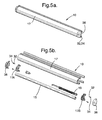
Figures 5a and 5b show an lower one of the pair of movable end rails of the roller blind assembly. -
Figures 1-3 show a rollerblind assembly 2 in aroof window 3, preferably in an upwardly inclined (rather than a horizontal) roof window. First and second (or left and right)side rails pane 7 of thewindow 3. A pair of upper and lower, longitudinal,movable end rails top ends bottom ends side rails bottom ends window pane 7. Theend rails roof window 3, are perpendicular to theside rails - An
upper end portion 12A of acovering 12 is attached to theupper end rail 8, and alower end portion 12B of thecovering 12 is attached to thelower end rail 10, so that the cover can be drawn across the pane, between theside rails end rails covering 12 is long and wide enough to cover substantially the whole window pane when the upper andlower end rails window pane 7. - Each upper and
lower end rail blind assembly 2 holds, within it, a longitudinal upper orlower roller lower housing portion covering 12, attached to theroller 14, can be wound and unwound from the roller. An upper or lower,large coil spring housing large coil spring housing covering 12, the large coil spring is unwound and provides a return torque to rewind the covering. At least one of the first and second ends of eachlarge coil spring end rail other end rail roller portion covering 12 within itshousing roller portion covering 12 within itshousing large coil spring 18, 19 (as discussed below) biases itsroller portion housing end rail - As shown in
Figure 4 , one end of eachlarge coil spring blind assembly 2 is fixed rotationally to one of the left and right,housing end caps housing end rail large coil spring roller portion covering 12, attached to its roller the large coil spring is unwound and provides a return torque to rewind the upper portion of the covering. Preferably, as seen fromFigure 2 , a left end 18A of an upperlarge coil spring 18 is fixed rotationally relative to theupper housing 16 of theupper end rail 8 and the right end 18B of the upperlarge coil spring 18 is fixed rotationally relative to theupper roller 14, and a right end 19B of a lowerlarge coil spring 18 is fixed rotationally relative to thelower housing 17 of thelower end rail 10 and the left end 19A of the lowerlarge coil spring 19 is fixed rotationally relative to thelower roller 15. - An advantage of having two
movable end rails rollers covering 12 is that the covering can be partially extended and positioned wherever a user requires along the length of theside rails -
Figure 4 also shows an arrangement for routing a first pair oftension cords side rails 4, 6 (not shown inFigure 4 ) and through the lower end rail 10 (not shown inFigure 4 ) in order to maintain the lower end rail at any desired vertical position when it is not being manipulated to extend or retract its lower portion 12b of thecovering 12. One of thefirst tension cords 20 extends from thetop end 4A of theleft side rail 4 downwardly through the left side rail, then longitudinally to the right through thelower end rail 10 and then downwardly through theright side rail 6 to itsbottom end 6B . The other one of thefirst tension cords 22 extends from thetop end 6A of theright side rail 6 downwardly through the right side rail, then longitudinally to the left through thelower end rail 10, and then downwardly through the left side rail to itsbottom end 4B. - This routing arrangement is preferably also used for routing a second pair of tension cords (not shown) through the
side rails upper end rail 8 in order to also maintain the upper end rail at any desired vertical position when it is not being manipulated to extend or retract itsupper portion 12A of thecovering 12. One of the second tension cords extends from thetop end 4A of theleft side rail 4 downwardly through the left side rail, then longitudinally to the right through theupper end rail 10, and then downwardly through theright side rail 6 to itsbottom end 6B, and the other one of the second tension cords extends from thetop end 6A of theright side rail 6 downwardly through the right side rail, then longitudinally to the left through theupper end rail 10, and then downwardly through theleft side rail 4 to its bottom end 4b. - Alternatively, a single pair of
tension cords bottom ends end rails - As shown in
Figures 3-5b , thehousing end caps end rails holes 24, through which the tension cords (e.g., 20, 22) can pass. As shown inFigure 4 , thetension cords hole 24 in each housing end cap. However, of course, separate through-holes could also be provided in each housing end cap for each tension cord. By means of the through-holes, the tension cords are able to pass longitudinally along the length of eachend rail housing 16. - As the
end rails side rails end rails holes 24 of thehousing end caps - The ends of the tension cords (e.g., 20, 22) are preferably secured to top and
bottom caps bottom ends side rails small coil springs 29. Thesmall coil springs 29 provide some tension to the tension cords (e.g., 20, 22) to provide an appropriate amount of frictional resistance to movement of the tension cords through the through-holes 24 and, hence, resistance to movement of theend rails small coil springs 29 allows theend rails side rails blind assembly 2 is not mounted in a roof window. In particular, theend rails side rails side rails - As seen from
Figure 3 , theside rails elongate channels 30 which face each other across the width of theblind assembly 2 and thewindow 3. Preferably, thechannel wall 30a adjacent thewindow pane 7 is longer than the opposite channel wall, remote from the window pane. This facilitates inserting the longitudinal ends of thehousing end caps elongate channels 30 because the longitudinal ends of the housing end caps can be inserted between the facing channel walls further from the window pane until the housing end caps abut thechannel walls 30a nearer to the window pane. Preferably, thechannels 30 are also sufficiently large to accommodate one or more tension cords (e.g., 20, 22), as well as the longitudinal ends of thehousing end caps - The longitudinal ends of the
housing end caps channels 30 and thereby assist in guiding movement of the end rails 8, 10 along the side rails. In this regard, as shown by way of example inFigures 5a and 5b , the longitudinal ends of each of the left and righthousing end caps 17A , 17b of thelower end rail 10 has a protrusion formed by a pair ofshafts 32. On eachshaft 32 is anannular member 34 that is rotatably mounted as a wheel to form a bearing. Theannular members 34 can rotate about axes parallel to the longitudinal axis of thelower end rail 10 and can fit into thechannel 30 of the left and right side rails 4, 6 . Eachannular member 34 has an outer diameter similar to the spacing between the opposite channel walls of the side rails, and the pair ofannular members 34 are arranged side by side in the direction of the extent of theright side rail 4 and its channel. In this way, thelower end rail 10 is more firmly and securely supported for movement along the side rails 4, 6. - As shown in
Figures 3 and5b , a finishingcap 36 is preferably provided over eachhousing end cap housing - As seen from
Figures 3-5b , eachlarge coil spring roller housing end rail - The
roller blind assembly 2 is preferably affixed to thepane 7 of theroof window 3 with a two-layer fastening material (not shown), such as a hook-and-loop fastener such as is commonly known as Velcro®. One of the two layers of the two-layer fastener is preferably adhered to the back faces of the side rails 4, 6 - i.e., the faces of the side rails closest, to the window pane and facing the window pane. The other layer of the fastener is adhered to at least corresponding sections of the window pane. For mounting the assembly, it is then merely a matter of properly positioning the side rails 4, 6 adjacent the appropriate portions of the window pane and pressing them together. - The
roller blind assembly 2, as described above, has previously been fully described in European patent application no.06252982.1, which was filed June 9, 2006 - As shown in
Figures 1-3 , theroller blind assembly 2 features a covering 12 which includes, at about its middle between themovable end rails pane 7 of aroof window 3. - This holding means 40 preferably is a thin longitudinal bar or
rod 42 which is adhered to the middle of the covering between the end rails. The left and right ends 44, 46 of thebar 42 are located within thechannels 30 of the left and right side rails 4, 6 and are held by the channel walls from moving towards or away from thewindow pane 7. In particular, the channel wall, remote from the window pane, prevents the ends 44, 46 of thebar 42 from falling out of thechannel 30 of each side rail due to the bar's weight and the weight of thecovering 12. Thereby, thebar 42 prevents the covering 12 from sagging significantly at about its middle, between themovable end rails bar 42 is adhered to the middle of the covering 12 over substantially the entire longitudinal width of the covering. It is also especially preferred that thebar 42 is made of a light weight, rigid, plastic, metal or wood material. For aesthetic reasons, it is particularly preferred thatbar 42 be adhered to a surface of the covering adjacent thewindow pane 7, but for ease of construction, it may be particularly preferred that the bar be adhered to a surface of the covering remote from the window pane as shown inFigures 1-3 . - Alternatively, the holding means 40 is preferably an adhesive coating that is on a surface of the covering 12 adjacent the
window pane 7 and that can releasably hold the covering's surface in contact with the adjacent surface of the window pane. It is especially preferred that the adhesive coating comprises a pressure-sensitive adhesive. Examples of such an adhesive coating are described inUS patents 5,108,811 ,5,972,453 ,6,306,508 , and6,705,054 and inUS patent application 2006/0032580 . A commercially available fabric with a releasble coating for use as the covering 12 can be obtained from Création Baumann Weberei und Färberei AG in Langenthal, Switzerland under the trademark "Gecko".
Claims (8)
- A roller blind assembly for a roof window that has a covering which includes, at about its middle between a pair of movable longitudinal end rails, means that extend longitudinally between a pair of parallel side rails for holding the covering adjacent to, or in contact with, a pane of the window.
- The roller blind assembly according to claim 1 wherein the holding means comprises a thin longitudinally-extending bar which is adhered to the middle of the covering and the ends of which are held by the side rails from moving away from the window pane.
- The roller blind assembly according to claim 2 wherein the bar is adhered to the middle of the covering over substantially the entire longitudinal width of the covering.
- The roller blind assembly according to claim 2 or 3 wherein the bar is made of a light weight, rigid plastic, metal or wood material.
- The roller blind assembly according to any one of claims 2-4 wherein the bar is adhered to a surface of the covering adjacent the window pane.
- The roller blind assembly according to any one of claims 2-4 wherein the bar is adhered to a surface of the covering remote from the window pane.
- The roller blind assembly according to claim 1 wherein the holding means comprises a coating that is on a surface of the covering adjacent the window pane and that can releasably adhere the covering's surface to an adjacent surface of the window pane.
- The roller blind assembly according to claim 7, wherein the adhesive coating comprises a pressure-sensitive adhesive.
Priority Applications (1)
| Application Number | Priority Date | Filing Date | Title |
|---|---|---|---|
| EP08252588.2A EP2020479B1 (en) | 2007-07-31 | 2008-07-30 | Roller blind for a roof window |
Applications Claiming Priority (2)
| Application Number | Priority Date | Filing Date | Title |
|---|---|---|---|
| EP07014974 | 2007-07-31 | ||
| EP08252588.2A EP2020479B1 (en) | 2007-07-31 | 2008-07-30 | Roller blind for a roof window |
Publications (3)
| Publication Number | Publication Date |
|---|---|
| EP2020479A2 true EP2020479A2 (en) | 2009-02-04 |
| EP2020479A3 EP2020479A3 (en) | 2013-04-03 |
| EP2020479B1 EP2020479B1 (en) | 2016-08-17 |
Family
ID=40019171
Family Applications (1)
| Application Number | Title | Priority Date | Filing Date |
|---|---|---|---|
| EP08252588.2A Not-in-force EP2020479B1 (en) | 2007-07-31 | 2008-07-30 | Roller blind for a roof window |
Country Status (1)
| Country | Link |
|---|---|
| EP (1) | EP2020479B1 (en) |
Cited By (5)
| Publication number | Priority date | Publication date | Assignee | Title |
|---|---|---|---|---|
| EP2733301A3 (en) * | 2012-11-01 | 2014-09-10 | Oceanair Marine Ltd | Improvements relating to retractable blinds |
| CN104632062A (en) * | 2015-01-30 | 2015-05-20 | 福建固美金属有限公司 | Intelligent bidirectional roller blind type window |
| CN105545197A (en) * | 2015-01-30 | 2016-05-04 | 福建固美金属有限公司 | Opening and closing method for manual bidirectional roller blind window |
| US20160130873A1 (en) * | 2014-11-10 | 2016-05-12 | Lock Antriebstechnik Gmbh | Winding device for covering of building openings |
| CN105715188A (en) * | 2015-01-30 | 2016-06-29 | 福建固美金属有限公司 | Opening and closing method of bidirectional roller shutter type window |
Citations (6)
| Publication number | Priority date | Publication date | Assignee | Title |
|---|---|---|---|---|
| US5108811A (en) | 1990-04-19 | 1992-04-28 | Mark Shippen | Removable, reusable, adhereable, window, insulation material |
| US5972453A (en) | 1996-09-03 | 1999-10-26 | Lintec Corporation | Removable film for the windows of motor vehicles |
| US6306508B1 (en) | 1999-05-24 | 2001-10-23 | Great Barrier Systems, Inc. | Restorative coating method for plastic and glass |
| US6705054B2 (en) | 2001-12-06 | 2004-03-16 | Thomas Bradley Pelton | Reusable hurricane window glass film protection |
| US20060032580A1 (en) | 2001-01-12 | 2006-02-16 | 3M Innovative Properties Company | Laminate from which decorative films can be applied to a substrate |
| WO2007141031A1 (en) | 2006-06-09 | 2007-12-13 | Hunter Douglas Industries B.V. | Covering and component parts thereof |
Family Cites Families (5)
| Publication number | Priority date | Publication date | Assignee | Title |
|---|---|---|---|---|
| CA1289010C (en) * | 1987-10-08 | 1991-09-17 | Marcel Dube | Sloped window with insulating shade |
| IT1220423B (en) * | 1988-03-16 | 1990-06-15 | Estfeller Srl | DRIVE MECHANISM FOR ROLLING BLINDS |
| DK172413B1 (en) * | 1996-06-18 | 1998-05-25 | Rasmussen Kann Ind As | Exterior screen for a tiltable skylight |
| AU2002950402A0 (en) * | 2002-07-26 | 2002-09-12 | Issam Abouloukme | Retractable selfrolling system for blinds awnings and covers |
| JP2004084403A (en) * | 2002-08-29 | 2004-03-18 | Nippon Eisei Center:Kk | Blind device |
-
2008
- 2008-07-30 EP EP08252588.2A patent/EP2020479B1/en not_active Not-in-force
Patent Citations (6)
| Publication number | Priority date | Publication date | Assignee | Title |
|---|---|---|---|---|
| US5108811A (en) | 1990-04-19 | 1992-04-28 | Mark Shippen | Removable, reusable, adhereable, window, insulation material |
| US5972453A (en) | 1996-09-03 | 1999-10-26 | Lintec Corporation | Removable film for the windows of motor vehicles |
| US6306508B1 (en) | 1999-05-24 | 2001-10-23 | Great Barrier Systems, Inc. | Restorative coating method for plastic and glass |
| US20060032580A1 (en) | 2001-01-12 | 2006-02-16 | 3M Innovative Properties Company | Laminate from which decorative films can be applied to a substrate |
| US6705054B2 (en) | 2001-12-06 | 2004-03-16 | Thomas Bradley Pelton | Reusable hurricane window glass film protection |
| WO2007141031A1 (en) | 2006-06-09 | 2007-12-13 | Hunter Douglas Industries B.V. | Covering and component parts thereof |
Cited By (8)
| Publication number | Priority date | Publication date | Assignee | Title |
|---|---|---|---|---|
| EP2733301A3 (en) * | 2012-11-01 | 2014-09-10 | Oceanair Marine Ltd | Improvements relating to retractable blinds |
| US20160130873A1 (en) * | 2014-11-10 | 2016-05-12 | Lock Antriebstechnik Gmbh | Winding device for covering of building openings |
| US10041295B2 (en) * | 2014-11-10 | 2018-08-07 | Lock Antriebstechnik Gmbh | Winding device for covering of building openings |
| CN104632062A (en) * | 2015-01-30 | 2015-05-20 | 福建固美金属有限公司 | Intelligent bidirectional roller blind type window |
| CN105545197A (en) * | 2015-01-30 | 2016-05-04 | 福建固美金属有限公司 | Opening and closing method for manual bidirectional roller blind window |
| CN105715188A (en) * | 2015-01-30 | 2016-06-29 | 福建固美金属有限公司 | Opening and closing method of bidirectional roller shutter type window |
| CN105545197B (en) * | 2015-01-30 | 2017-03-08 | 福建固美金属有限公司 | A kind of method of switching of manual bidirectional rolling window |
| CN105715188B (en) * | 2015-01-30 | 2017-08-15 | 福建固美金属有限公司 | A kind of method of switching of tow-way shutter window |
Also Published As
| Publication number | Publication date |
|---|---|
| EP2020479A3 (en) | 2013-04-03 |
| EP2020479B1 (en) | 2016-08-17 |
Similar Documents
| Publication | Publication Date | Title |
|---|---|---|
| EP2662522B1 (en) | Device for tensioning or pre-tensioning a rollable fly screen | |
| EP3175073B1 (en) | A retrofitable retractable screen system | |
| JP5308332B2 (en) | Covering device and components thereof | |
| JP3163685U (en) | Blind system | |
| EP2301783B1 (en) | Roll-up shade apparatus for vehicle | |
| EP2020479A2 (en) | Roller blind for a roof window | |
| US8408274B2 (en) | Architectural apparatus and method | |
| US20050241779A1 (en) | Retractable self rolling blind, awning or cover apparatus | |
| US8839840B2 (en) | Roller shade assembly for stiff shade materials | |
| WO2018232439A1 (en) | A low profile retrofitable retractable screen system | |
| US4834160A (en) | Awning deployment and tensioning system | |
| US5819835A (en) | Roll-up divider | |
| EP0678148B1 (en) | Tape drive extendable and retractable awning assembly | |
| US6948542B2 (en) | Retractable self rolling blind awning or cover apparatus | |
| EP3184712A2 (en) | Retractable shade system | |
| US7036547B1 (en) | Height adjustable pleated shade | |
| EP2957707A1 (en) | Blind assembly and method of attaching a shade material to a winding core and/or a rail of a blind assembly | |
| US11391088B2 (en) | Roller blind assembly | |
| AU2020100049A4 (en) | A low profile retrofitable retractable screen system | |
| US9057219B1 (en) | Window covering with integrated side track | |
| NL2004599C2 (en) | Window covering element and window covering system. | |
| EP2358966B1 (en) | Conservatory roof window with screen mountable inside or outside | |
| CA2719458A1 (en) | Head rail for an adjustable roller shade | |
| EP2140148B1 (en) | A method for fastening a screening body to a bottom element in a screening arrangement | |
| KR20220074213A (en) | Fabric tension device |
Legal Events
| Date | Code | Title | Description |
|---|---|---|---|
| PUAI | Public reference made under article 153(3) epc to a published international application that has entered the european phase |
Free format text: ORIGINAL CODE: 0009012 |
|
| AK | Designated contracting states |
Kind code of ref document: A2 Designated state(s): AT BE BG CH CY CZ DE DK EE ES FI FR GB GR HR HU IE IS IT LI LT LU LV MC MT NL NO PL PT RO SE SI SK TR |
|
| AX | Request for extension of the european patent |
Extension state: AL BA MK RS |
|
| PUAL | Search report despatched |
Free format text: ORIGINAL CODE: 0009013 |
|
| AK | Designated contracting states |
Kind code of ref document: A3 Designated state(s): AT BE BG CH CY CZ DE DK EE ES FI FR GB GR HR HU IE IS IT LI LT LU LV MC MT NL NO PL PT RO SE SI SK TR |
|
| AX | Request for extension of the european patent |
Extension state: AL BA MK RS |
|
| RIC1 | Information provided on ipc code assigned before grant |
Ipc: E06B 9/58 20060101ALI20130228BHEP Ipc: E06B 9/64 20060101ALI20130228BHEP Ipc: E06B 9/66 20060101ALI20130228BHEP Ipc: E06B 9/40 20060101AFI20130228BHEP |
|
| 17P | Request for examination filed |
Effective date: 20131003 |
|
| RBV | Designated contracting states (corrected) |
Designated state(s): AT BE BG CH CY CZ DE DK EE ES FI FR GB GR HR HU IE IS IT LI LT LU LV MC MT NL NO PL PT RO SE SI SK TR |
|
| AKX | Designation fees paid |
Designated state(s): AT BE BG CH CY CZ DE DK EE ES FI FR GB GR HR HU IE IS IT LI LT LU LV MC MT NL NO PL PT RO SE SI SK TR |
|
| GRAP | Despatch of communication of intention to grant a patent |
Free format text: ORIGINAL CODE: EPIDOSNIGR1 |
|
| INTG | Intention to grant announced |
Effective date: 20160307 |
|
| GRAS | Grant fee paid |
Free format text: ORIGINAL CODE: EPIDOSNIGR3 |
|
| GRAA | (expected) grant |
Free format text: ORIGINAL CODE: 0009210 |
|
| AK | Designated contracting states |
Kind code of ref document: B1 Designated state(s): AT BE BG CH CY CZ DE DK EE ES FI FR GB GR HR HU IE IS IT LI LT LU LV MC MT NL NO PL PT RO SE SI SK TR |
|
| REG | Reference to a national code |
Ref country code: GB Ref legal event code: FG4D |
|
| REG | Reference to a national code |
Ref country code: CH Ref legal event code: EP |
|
| REG | Reference to a national code |
Ref country code: IE Ref legal event code: FG4D |
|
| REG | Reference to a national code |
Ref country code: AT Ref legal event code: REF Ref document number: 821284 Country of ref document: AT Kind code of ref document: T Effective date: 20160915 |
|
| REG | Reference to a national code |
Ref country code: DE Ref legal event code: R096 Ref document number: 602008045691 Country of ref document: DE |
|
| REG | Reference to a national code |
Ref country code: NL Ref legal event code: MP Effective date: 20160817 |
|
| REG | Reference to a national code |
Ref country code: LT Ref legal event code: MG4D |
|
| REG | Reference to a national code |
Ref country code: AT Ref legal event code: MK05 Ref document number: 821284 Country of ref document: AT Kind code of ref document: T Effective date: 20160817 |
|
| PG25 | Lapsed in a contracting state [announced via postgrant information from national office to epo] |
Ref country code: NO Free format text: LAPSE BECAUSE OF FAILURE TO SUBMIT A TRANSLATION OF THE DESCRIPTION OR TO PAY THE FEE WITHIN THE PRESCRIBED TIME-LIMIT Effective date: 20161117 Ref country code: LT Free format text: LAPSE BECAUSE OF FAILURE TO SUBMIT A TRANSLATION OF THE DESCRIPTION OR TO PAY THE FEE WITHIN THE PRESCRIBED TIME-LIMIT Effective date: 20160817 Ref country code: IT Free format text: LAPSE BECAUSE OF FAILURE TO SUBMIT A TRANSLATION OF THE DESCRIPTION OR TO PAY THE FEE WITHIN THE PRESCRIBED TIME-LIMIT Effective date: 20160817 Ref country code: FI Free format text: LAPSE BECAUSE OF FAILURE TO SUBMIT A TRANSLATION OF THE DESCRIPTION OR TO PAY THE FEE WITHIN THE PRESCRIBED TIME-LIMIT Effective date: 20160817 Ref country code: HR Free format text: LAPSE BECAUSE OF FAILURE TO SUBMIT A TRANSLATION OF THE DESCRIPTION OR TO PAY THE FEE WITHIN THE PRESCRIBED TIME-LIMIT Effective date: 20160817 Ref country code: NL Free format text: LAPSE BECAUSE OF FAILURE TO SUBMIT A TRANSLATION OF THE DESCRIPTION OR TO PAY THE FEE WITHIN THE PRESCRIBED TIME-LIMIT Effective date: 20160817 |
|
| PG25 | Lapsed in a contracting state [announced via postgrant information from national office to epo] |
Ref country code: LV Free format text: LAPSE BECAUSE OF FAILURE TO SUBMIT A TRANSLATION OF THE DESCRIPTION OR TO PAY THE FEE WITHIN THE PRESCRIBED TIME-LIMIT Effective date: 20160817 Ref country code: AT Free format text: LAPSE BECAUSE OF FAILURE TO SUBMIT A TRANSLATION OF THE DESCRIPTION OR TO PAY THE FEE WITHIN THE PRESCRIBED TIME-LIMIT Effective date: 20160817 Ref country code: GR Free format text: LAPSE BECAUSE OF FAILURE TO SUBMIT A TRANSLATION OF THE DESCRIPTION OR TO PAY THE FEE WITHIN THE PRESCRIBED TIME-LIMIT Effective date: 20161118 Ref country code: SE Free format text: LAPSE BECAUSE OF FAILURE TO SUBMIT A TRANSLATION OF THE DESCRIPTION OR TO PAY THE FEE WITHIN THE PRESCRIBED TIME-LIMIT Effective date: 20160817 Ref country code: PT Free format text: LAPSE BECAUSE OF FAILURE TO SUBMIT A TRANSLATION OF THE DESCRIPTION OR TO PAY THE FEE WITHIN THE PRESCRIBED TIME-LIMIT Effective date: 20161219 Ref country code: PL Free format text: LAPSE BECAUSE OF FAILURE TO SUBMIT A TRANSLATION OF THE DESCRIPTION OR TO PAY THE FEE WITHIN THE PRESCRIBED TIME-LIMIT Effective date: 20160817 Ref country code: ES Free format text: LAPSE BECAUSE OF FAILURE TO SUBMIT A TRANSLATION OF THE DESCRIPTION OR TO PAY THE FEE WITHIN THE PRESCRIBED TIME-LIMIT Effective date: 20160817 |
|
| PG25 | Lapsed in a contracting state [announced via postgrant information from national office to epo] |
Ref country code: EE Free format text: LAPSE BECAUSE OF FAILURE TO SUBMIT A TRANSLATION OF THE DESCRIPTION OR TO PAY THE FEE WITHIN THE PRESCRIBED TIME-LIMIT Effective date: 20160817 Ref country code: RO Free format text: LAPSE BECAUSE OF FAILURE TO SUBMIT A TRANSLATION OF THE DESCRIPTION OR TO PAY THE FEE WITHIN THE PRESCRIBED TIME-LIMIT Effective date: 20160817 |
|
| REG | Reference to a national code |
Ref country code: DE Ref legal event code: R097 Ref document number: 602008045691 Country of ref document: DE |
|
| PG25 | Lapsed in a contracting state [announced via postgrant information from national office to epo] |
Ref country code: DK Free format text: LAPSE BECAUSE OF FAILURE TO SUBMIT A TRANSLATION OF THE DESCRIPTION OR TO PAY THE FEE WITHIN THE PRESCRIBED TIME-LIMIT Effective date: 20160817 Ref country code: BG Free format text: LAPSE BECAUSE OF FAILURE TO SUBMIT A TRANSLATION OF THE DESCRIPTION OR TO PAY THE FEE WITHIN THE PRESCRIBED TIME-LIMIT Effective date: 20161117 Ref country code: SK Free format text: LAPSE BECAUSE OF FAILURE TO SUBMIT A TRANSLATION OF THE DESCRIPTION OR TO PAY THE FEE WITHIN THE PRESCRIBED TIME-LIMIT Effective date: 20160817 Ref country code: BE Free format text: LAPSE BECAUSE OF FAILURE TO SUBMIT A TRANSLATION OF THE DESCRIPTION OR TO PAY THE FEE WITHIN THE PRESCRIBED TIME-LIMIT Effective date: 20160817 Ref country code: CZ Free format text: LAPSE BECAUSE OF FAILURE TO SUBMIT A TRANSLATION OF THE DESCRIPTION OR TO PAY THE FEE WITHIN THE PRESCRIBED TIME-LIMIT Effective date: 20160817 |
|
| PLBE | No opposition filed within time limit |
Free format text: ORIGINAL CODE: 0009261 |
|
| STAA | Information on the status of an ep patent application or granted ep patent |
Free format text: STATUS: NO OPPOSITION FILED WITHIN TIME LIMIT |
|
| 26N | No opposition filed |
Effective date: 20170518 |
|
| PG25 | Lapsed in a contracting state [announced via postgrant information from national office to epo] |
Ref country code: SI Free format text: LAPSE BECAUSE OF FAILURE TO SUBMIT A TRANSLATION OF THE DESCRIPTION OR TO PAY THE FEE WITHIN THE PRESCRIBED TIME-LIMIT Effective date: 20160817 |
|
| REG | Reference to a national code |
Ref country code: CH Ref legal event code: PL |
|
| GBPC | Gb: european patent ceased through non-payment of renewal fee |
Effective date: 20170730 |
|
| REG | Reference to a national code |
Ref country code: FR Ref legal event code: ST Effective date: 20180330 |
|
| PG25 | Lapsed in a contracting state [announced via postgrant information from national office to epo] |
Ref country code: GB Free format text: LAPSE BECAUSE OF NON-PAYMENT OF DUE FEES Effective date: 20170730 Ref country code: CH Free format text: LAPSE BECAUSE OF NON-PAYMENT OF DUE FEES Effective date: 20170731 Ref country code: LI Free format text: LAPSE BECAUSE OF NON-PAYMENT OF DUE FEES Effective date: 20170731 |
|
| REG | Reference to a national code |
Ref country code: IE Ref legal event code: MM4A |
|
| PG25 | Lapsed in a contracting state [announced via postgrant information from national office to epo] |
Ref country code: FR Free format text: LAPSE BECAUSE OF NON-PAYMENT OF DUE FEES Effective date: 20170731 |
|
| PG25 | Lapsed in a contracting state [announced via postgrant information from national office to epo] |
Ref country code: LU Free format text: LAPSE BECAUSE OF NON-PAYMENT OF DUE FEES Effective date: 20170730 |
|
| PG25 | Lapsed in a contracting state [announced via postgrant information from national office to epo] |
Ref country code: IE Free format text: LAPSE BECAUSE OF NON-PAYMENT OF DUE FEES Effective date: 20170730 |
|
| PG25 | Lapsed in a contracting state [announced via postgrant information from national office to epo] |
Ref country code: MT Free format text: LAPSE BECAUSE OF NON-PAYMENT OF DUE FEES Effective date: 20170730 |
|
| PG25 | Lapsed in a contracting state [announced via postgrant information from national office to epo] |
Ref country code: MC Free format text: LAPSE BECAUSE OF FAILURE TO SUBMIT A TRANSLATION OF THE DESCRIPTION OR TO PAY THE FEE WITHIN THE PRESCRIBED TIME-LIMIT Effective date: 20160817 Ref country code: HU Free format text: LAPSE BECAUSE OF FAILURE TO SUBMIT A TRANSLATION OF THE DESCRIPTION OR TO PAY THE FEE WITHIN THE PRESCRIBED TIME-LIMIT; INVALID AB INITIO Effective date: 20080730 |
|
| PG25 | Lapsed in a contracting state [announced via postgrant information from national office to epo] |
Ref country code: CY Free format text: LAPSE BECAUSE OF NON-PAYMENT OF DUE FEES Effective date: 20160817 |
|
| PGFP | Annual fee paid to national office [announced via postgrant information from national office to epo] |
Ref country code: DE Payment date: 20190716 Year of fee payment: 12 |
|
| PG25 | Lapsed in a contracting state [announced via postgrant information from national office to epo] |
Ref country code: TR Free format text: LAPSE BECAUSE OF FAILURE TO SUBMIT A TRANSLATION OF THE DESCRIPTION OR TO PAY THE FEE WITHIN THE PRESCRIBED TIME-LIMIT Effective date: 20160817 |
|
| PG25 | Lapsed in a contracting state [announced via postgrant information from national office to epo] |
Ref country code: IS Free format text: LAPSE BECAUSE OF FAILURE TO SUBMIT A TRANSLATION OF THE DESCRIPTION OR TO PAY THE FEE WITHIN THE PRESCRIBED TIME-LIMIT Effective date: 20161217 |
|
| REG | Reference to a national code |
Ref country code: DE Ref legal event code: R119 Ref document number: 602008045691 Country of ref document: DE |
|
| PG25 | Lapsed in a contracting state [announced via postgrant information from national office to epo] |
Ref country code: DE Free format text: LAPSE BECAUSE OF NON-PAYMENT OF DUE FEES Effective date: 20210202 |