EP2020486A2 - Honeycomb filter for clarifying exhaust gas - Google Patents
Honeycomb filter for clarifying exhaust gas Download PDFInfo
- Publication number
- EP2020486A2 EP2020486A2 EP08169564A EP08169564A EP2020486A2 EP 2020486 A2 EP2020486 A2 EP 2020486A2 EP 08169564 A EP08169564 A EP 08169564A EP 08169564 A EP08169564 A EP 08169564A EP 2020486 A2 EP2020486 A2 EP 2020486A2
- Authority
- EP
- European Patent Office
- Prior art keywords
- honeycomb filter
- plug
- length
- exhaust gases
- ceramic
- Prior art date
- Legal status (The legal status is an assumption and is not a legal conclusion. Google has not performed a legal analysis and makes no representation as to the accuracy of the status listed.)
- Withdrawn
Links
- 239000000919 ceramic Substances 0.000 claims abstract description 182
- 239000007789 gas Substances 0.000 claims abstract description 129
- 238000005452 bending Methods 0.000 claims abstract description 95
- 238000000034 method Methods 0.000 claims description 145
- 230000008569 process Effects 0.000 claims description 122
- 239000003054 catalyst Substances 0.000 claims description 32
- 238000010438 heat treatment Methods 0.000 claims description 15
- 239000010419 fine particle Substances 0.000 claims description 5
- 238000011001 backwashing Methods 0.000 claims description 3
- 239000002245 particle Substances 0.000 abstract description 71
- 241000264877 Hippospongia communis Species 0.000 description 323
- 239000003566 sealing material Substances 0.000 description 64
- HBMJWWWQQXIZIP-UHFFFAOYSA-N silicon carbide Chemical compound [Si+]#[C-] HBMJWWWQQXIZIP-UHFFFAOYSA-N 0.000 description 57
- 229910010271 silicon carbide Inorganic materials 0.000 description 56
- 230000000052 comparative effect Effects 0.000 description 46
- 229910052878 cordierite Inorganic materials 0.000 description 46
- JSKIRARMQDRGJZ-UHFFFAOYSA-N dimagnesium dioxido-bis[(1-oxido-3-oxo-2,4,6,8,9-pentaoxa-1,3-disila-5,7-dialuminabicyclo[3.3.1]nonan-7-yl)oxy]silane Chemical compound [Mg++].[Mg++].[O-][Si]([O-])(O[Al]1O[Al]2O[Si](=O)O[Si]([O-])(O1)O2)O[Al]1O[Al]2O[Si](=O)O[Si]([O-])(O1)O2 JSKIRARMQDRGJZ-UHFFFAOYSA-N 0.000 description 46
- 238000007789 sealing Methods 0.000 description 37
- 239000010410 layer Substances 0.000 description 36
- 239000000463 material Substances 0.000 description 34
- 238000005192 partition Methods 0.000 description 28
- 239000000843 powder Substances 0.000 description 28
- VYPSYNLAJGMNEJ-UHFFFAOYSA-N Silicium dioxide Chemical compound O=[Si]=O VYPSYNLAJGMNEJ-UHFFFAOYSA-N 0.000 description 26
- 239000011230 binding agent Substances 0.000 description 22
- 238000010304 firing Methods 0.000 description 22
- 239000002994 raw material Substances 0.000 description 20
- 238000004064 recycling Methods 0.000 description 20
- PNEYBMLMFCGWSK-UHFFFAOYSA-N aluminium oxide Inorganic materials [O-2].[O-2].[O-2].[Al+3].[Al+3] PNEYBMLMFCGWSK-UHFFFAOYSA-N 0.000 description 19
- -1 silicate compound Chemical class 0.000 description 18
- 238000002485 combustion reaction Methods 0.000 description 17
- 239000000835 fiber Substances 0.000 description 17
- 238000007599 discharging Methods 0.000 description 16
- LYCAIKOWRPUZTN-UHFFFAOYSA-N Ethylene glycol Chemical compound OCCO LYCAIKOWRPUZTN-UHFFFAOYSA-N 0.000 description 15
- 239000000377 silicon dioxide Substances 0.000 description 14
- 230000001590 oxidative effect Effects 0.000 description 13
- 239000011148 porous material Substances 0.000 description 13
- 238000004519 manufacturing process Methods 0.000 description 11
- 238000005238 degreasing Methods 0.000 description 10
- XLYOFNOQVPJJNP-UHFFFAOYSA-N water Substances O XLYOFNOQVPJJNP-UHFFFAOYSA-N 0.000 description 10
- 229910010293 ceramic material Inorganic materials 0.000 description 9
- 239000002270 dispersing agent Substances 0.000 description 9
- 238000001125 extrusion Methods 0.000 description 9
- 239000000203 mixture Substances 0.000 description 9
- 239000012784 inorganic fiber Substances 0.000 description 8
- 229910019142 PO4 Inorganic materials 0.000 description 7
- 150000005215 alkyl ethers Chemical class 0.000 description 7
- 238000001914 filtration Methods 0.000 description 7
- 239000010452 phosphate Substances 0.000 description 7
- 229920003171 Poly (ethylene oxide) Polymers 0.000 description 6
- 229920000609 methyl cellulose Polymers 0.000 description 6
- 239000001923 methylcellulose Substances 0.000 description 6
- 235000010981 methylcellulose Nutrition 0.000 description 6
- 238000000465 moulding Methods 0.000 description 6
- NBIIXXVUZAFLBC-UHFFFAOYSA-K phosphate Chemical compound [O-]P([O-])([O-])=O NBIIXXVUZAFLBC-UHFFFAOYSA-K 0.000 description 6
- 239000002904 solvent Substances 0.000 description 6
- 239000005995 Aluminium silicate Substances 0.000 description 5
- OKTJSMMVPCPJKN-UHFFFAOYSA-N Carbon Chemical compound [C] OKTJSMMVPCPJKN-UHFFFAOYSA-N 0.000 description 5
- 229920002134 Carboxymethyl cellulose Polymers 0.000 description 5
- WNROFYMDJYEPJX-UHFFFAOYSA-K aluminium hydroxide Chemical compound [OH-].[OH-].[OH-].[Al+3] WNROFYMDJYEPJX-UHFFFAOYSA-K 0.000 description 5
- 235000012211 aluminium silicate Nutrition 0.000 description 5
- 239000001768 carboxy methyl cellulose Substances 0.000 description 5
- 235000010948 carboxy methyl cellulose Nutrition 0.000 description 5
- 239000008112 carboxymethyl-cellulose Substances 0.000 description 5
- 229940105329 carboxymethylcellulose Drugs 0.000 description 5
- 239000010439 graphite Substances 0.000 description 5
- 229910002804 graphite Inorganic materials 0.000 description 5
- NLYAJNPCOHFWQQ-UHFFFAOYSA-N kaolin Chemical compound O.O.O=[Al]O[Si](=O)O[Si](=O)O[Al]=O NLYAJNPCOHFWQQ-UHFFFAOYSA-N 0.000 description 5
- 239000000314 lubricant Substances 0.000 description 5
- 239000000454 talc Substances 0.000 description 5
- 229910052623 talc Inorganic materials 0.000 description 5
- SOGAXMICEFXMKE-UHFFFAOYSA-N Butylmethacrylate Chemical compound CCCCOC(=O)C(C)=C SOGAXMICEFXMKE-UHFFFAOYSA-N 0.000 description 4
- 239000004215 Carbon black (E152) Substances 0.000 description 4
- OKKJLVBELUTLKV-UHFFFAOYSA-N Methanol Chemical group OC OKKJLVBELUTLKV-UHFFFAOYSA-N 0.000 description 4
- 125000000217 alkyl group Chemical group 0.000 description 4
- 230000015556 catabolic process Effects 0.000 description 4
- 238000006243 chemical reaction Methods 0.000 description 4
- 239000003795 chemical substances by application Substances 0.000 description 4
- 238000006731 degradation reaction Methods 0.000 description 4
- 229930195733 hydrocarbon Natural products 0.000 description 4
- 150000002430 hydrocarbons Chemical class 0.000 description 4
- 239000010954 inorganic particle Substances 0.000 description 4
- 238000002156 mixing Methods 0.000 description 4
- 230000002093 peripheral effect Effects 0.000 description 4
- 229920001451 polypropylene glycol Polymers 0.000 description 4
- RMAQACBXLXPBSY-UHFFFAOYSA-N silicic acid Chemical compound O[Si](O)(O)O RMAQACBXLXPBSY-UHFFFAOYSA-N 0.000 description 4
- OADIZUFHUPTFAG-UHFFFAOYSA-N 2-[2-(2-ethylhexoxy)ethoxy]ethanol Chemical compound CCCCC(CC)COCCOCCO OADIZUFHUPTFAG-UHFFFAOYSA-N 0.000 description 3
- NIXOWILDQLNWCW-UHFFFAOYSA-M Acrylate Chemical compound [O-]C(=O)C=C NIXOWILDQLNWCW-UHFFFAOYSA-M 0.000 description 3
- UHOVQNZJYSORNB-UHFFFAOYSA-N Benzene Chemical compound C1=CC=CC=C1 UHOVQNZJYSORNB-UHFFFAOYSA-N 0.000 description 3
- XUIMIQQOPSSXEZ-UHFFFAOYSA-N Silicon Chemical compound [Si] XUIMIQQOPSSXEZ-UHFFFAOYSA-N 0.000 description 3
- 150000001875 compounds Chemical class 0.000 description 3
- 238000005520 cutting process Methods 0.000 description 3
- KZHJGOXRZJKJNY-UHFFFAOYSA-N dioxosilane;oxo(oxoalumanyloxy)alumane Chemical compound O=[Si]=O.O=[Si]=O.O=[Al]O[Al]=O.O=[Al]O[Al]=O.O=[Al]O[Al]=O KZHJGOXRZJKJNY-UHFFFAOYSA-N 0.000 description 3
- 238000011156 evaluation Methods 0.000 description 3
- 229910052863 mullite Inorganic materials 0.000 description 3
- 150000004767 nitrides Chemical class 0.000 description 3
- 230000000737 periodic effect Effects 0.000 description 3
- 238000004080 punching Methods 0.000 description 3
- 230000009467 reduction Effects 0.000 description 3
- 229910052710 silicon Inorganic materials 0.000 description 3
- 239000010703 silicon Substances 0.000 description 3
- 229910052582 BN Inorganic materials 0.000 description 2
- PZNSFCLAULLKQX-UHFFFAOYSA-N Boron nitride Chemical compound N#B PZNSFCLAULLKQX-UHFFFAOYSA-N 0.000 description 2
- LFQSCWFLJHTTHZ-UHFFFAOYSA-N Ethanol Chemical compound CCO LFQSCWFLJHTTHZ-UHFFFAOYSA-N 0.000 description 2
- KDLHZDBZIXYQEI-UHFFFAOYSA-N Palladium Chemical compound [Pd] KDLHZDBZIXYQEI-UHFFFAOYSA-N 0.000 description 2
- 229910052581 Si3N4 Inorganic materials 0.000 description 2
- GWEVSGVZZGPLCZ-UHFFFAOYSA-N Titan oxide Chemical compound O=[Ti]=O GWEVSGVZZGPLCZ-UHFFFAOYSA-N 0.000 description 2
- MCMNRKCIXSYSNV-UHFFFAOYSA-N Zirconium dioxide Chemical compound O=[Zr]=O MCMNRKCIXSYSNV-UHFFFAOYSA-N 0.000 description 2
- 239000000853 adhesive Substances 0.000 description 2
- 230000001070 adhesive effect Effects 0.000 description 2
- 239000012300 argon atmosphere Substances 0.000 description 2
- 239000002585 base Substances 0.000 description 2
- 239000007767 bonding agent Substances 0.000 description 2
- 230000006378 damage Effects 0.000 description 2
- 229910003460 diamond Inorganic materials 0.000 description 2
- 239000010432 diamond Substances 0.000 description 2
- 239000010881 fly ash Substances 0.000 description 2
- 229910000510 noble metal Inorganic materials 0.000 description 2
- 229910052574 oxide ceramic Inorganic materials 0.000 description 2
- 239000011224 oxide ceramic Substances 0.000 description 2
- BASFCYQUMIYNBI-UHFFFAOYSA-N platinum Chemical compound [Pt] BASFCYQUMIYNBI-UHFFFAOYSA-N 0.000 description 2
- 238000013001 point bending Methods 0.000 description 2
- 239000011347 resin Substances 0.000 description 2
- 229920005989 resin Polymers 0.000 description 2
- HQVNEWCFYHHQES-UHFFFAOYSA-N silicon nitride Chemical compound N12[Si]34N5[Si]62N3[Si]51N64 HQVNEWCFYHHQES-UHFFFAOYSA-N 0.000 description 2
- 238000003756 stirring Methods 0.000 description 2
- 238000007088 Archimedes method Methods 0.000 description 1
- 239000004375 Dextrin Substances 0.000 description 1
- 229920001353 Dextrin Polymers 0.000 description 1
- 239000001856 Ethyl cellulose Substances 0.000 description 1
- ZZSNKZQZMQGXPY-UHFFFAOYSA-N Ethyl cellulose Chemical compound CCOCC1OC(OC)C(OCC)C(OCC)C1OC1C(O)C(O)C(OC)C(CO)O1 ZZSNKZQZMQGXPY-UHFFFAOYSA-N 0.000 description 1
- IAYPIBMASNFSPL-UHFFFAOYSA-N Ethylene oxide Chemical compound C1CO1 IAYPIBMASNFSPL-UHFFFAOYSA-N 0.000 description 1
- 229920000663 Hydroxyethyl cellulose Polymers 0.000 description 1
- 239000004354 Hydroxyethyl cellulose Substances 0.000 description 1
- BPQQTUXANYXVAA-UHFFFAOYSA-N Orthosilicate Chemical compound [O-][Si]([O-])([O-])[O-] BPQQTUXANYXVAA-UHFFFAOYSA-N 0.000 description 1
- 239000002202 Polyethylene glycol Substances 0.000 description 1
- 239000004372 Polyvinyl alcohol Substances 0.000 description 1
- GOOHAUXETOMSMM-UHFFFAOYSA-N Propylene oxide Chemical compound CC1CO1 GOOHAUXETOMSMM-UHFFFAOYSA-N 0.000 description 1
- NRTOMJZYCJJWKI-UHFFFAOYSA-N Titanium nitride Chemical compound [Ti]#N NRTOMJZYCJJWKI-UHFFFAOYSA-N 0.000 description 1
- 229910026551 ZrC Inorganic materials 0.000 description 1
- OTCHGXYCWNXDOA-UHFFFAOYSA-N [C].[Zr] Chemical compound [C].[Zr] OTCHGXYCWNXDOA-UHFFFAOYSA-N 0.000 description 1
- NIXOWILDQLNWCW-UHFFFAOYSA-N acrylic acid group Chemical group C(C=C)(=O)O NIXOWILDQLNWCW-UHFFFAOYSA-N 0.000 description 1
- 239000012790 adhesive layer Substances 0.000 description 1
- 229910052783 alkali metal Inorganic materials 0.000 description 1
- 150000001340 alkali metals Chemical class 0.000 description 1
- 229910052784 alkaline earth metal Inorganic materials 0.000 description 1
- 125000005037 alkyl phenyl group Chemical group 0.000 description 1
- QVGXLLKOCUKJST-UHFFFAOYSA-N atomic oxygen Chemical group [O] QVGXLLKOCUKJST-UHFFFAOYSA-N 0.000 description 1
- 230000008901 benefit Effects 0.000 description 1
- 230000015572 biosynthetic process Effects 0.000 description 1
- 229920001400 block copolymer Polymers 0.000 description 1
- 238000007664 blowing Methods 0.000 description 1
- 125000004432 carbon atom Chemical group C* 0.000 description 1
- 229910052681 coesite Inorganic materials 0.000 description 1
- 238000010276 construction Methods 0.000 description 1
- 229910052906 cristobalite Inorganic materials 0.000 description 1
- 230000006837 decompression Effects 0.000 description 1
- 235000019425 dextrin Nutrition 0.000 description 1
- 235000014113 dietary fatty acids Nutrition 0.000 description 1
- 239000006185 dispersion Substances 0.000 description 1
- 239000003822 epoxy resin Substances 0.000 description 1
- RTZKZFJDLAIYFH-UHFFFAOYSA-N ether Substances CCOCC RTZKZFJDLAIYFH-UHFFFAOYSA-N 0.000 description 1
- 229920001249 ethyl cellulose Polymers 0.000 description 1
- 235000019325 ethyl cellulose Nutrition 0.000 description 1
- 239000000194 fatty acid Substances 0.000 description 1
- 229930195729 fatty acid Natural products 0.000 description 1
- 150000004665 fatty acids Chemical class 0.000 description 1
- 239000011521 glass Substances 0.000 description 1
- LNEPOXFFQSENCJ-UHFFFAOYSA-N haloperidol Chemical compound C1CC(O)(C=2C=CC(Cl)=CC=2)CCN1CCCC(=O)C1=CC=C(F)C=C1 LNEPOXFFQSENCJ-UHFFFAOYSA-N 0.000 description 1
- 235000019447 hydroxyethyl cellulose Nutrition 0.000 description 1
- 229940071826 hydroxyethyl cellulose Drugs 0.000 description 1
- 238000005304 joining Methods 0.000 description 1
- 238000010030 laminating Methods 0.000 description 1
- 238000003475 lamination Methods 0.000 description 1
- 230000007774 longterm Effects 0.000 description 1
- 238000005259 measurement Methods 0.000 description 1
- QSHDDOUJBYECFT-UHFFFAOYSA-N mercury Chemical compound [Hg] QSHDDOUJBYECFT-UHFFFAOYSA-N 0.000 description 1
- 229910052753 mercury Inorganic materials 0.000 description 1
- 229910052751 metal Inorganic materials 0.000 description 1
- 239000002184 metal Substances 0.000 description 1
- 150000001247 metal acetylides Chemical class 0.000 description 1
- 229960002900 methylcellulose Drugs 0.000 description 1
- NFFIWVVINABMKP-UHFFFAOYSA-N methylidynetantalum Chemical compound [Ta]#C NFFIWVVINABMKP-UHFFFAOYSA-N 0.000 description 1
- 125000004108 n-butyl group Chemical group [H]C([H])([H])C([H])([H])C([H])([H])C([H])([H])* 0.000 description 1
- 125000001280 n-hexyl group Chemical group C(CCCCC)* 0.000 description 1
- 125000000740 n-pentyl group Chemical group [H]C([H])([H])C([H])([H])C([H])([H])C([H])([H])C([H])([H])* 0.000 description 1
- 239000003960 organic solvent Substances 0.000 description 1
- 230000003647 oxidation Effects 0.000 description 1
- 238000007254 oxidation reaction Methods 0.000 description 1
- 239000001301 oxygen Substances 0.000 description 1
- 229910052760 oxygen Inorganic materials 0.000 description 1
- 229910052763 palladium Inorganic materials 0.000 description 1
- 230000035699 permeability Effects 0.000 description 1
- 239000005011 phenolic resin Substances 0.000 description 1
- 229910052697 platinum Inorganic materials 0.000 description 1
- 229920000647 polyepoxide Polymers 0.000 description 1
- 229920001223 polyethylene glycol Polymers 0.000 description 1
- 229920002503 polyoxyethylene-polyoxypropylene Polymers 0.000 description 1
- 229920002451 polyvinyl alcohol Polymers 0.000 description 1
- 235000019422 polyvinyl alcohol Nutrition 0.000 description 1
- 230000001376 precipitating effect Effects 0.000 description 1
- 238000001556 precipitation Methods 0.000 description 1
- 238000003825 pressing Methods 0.000 description 1
- 229910052761 rare earth metal Inorganic materials 0.000 description 1
- 229910052703 rhodium Inorganic materials 0.000 description 1
- 239000010948 rhodium Substances 0.000 description 1
- MHOVAHRLVXNVSD-UHFFFAOYSA-N rhodium atom Chemical compound [Rh] MHOVAHRLVXNVSD-UHFFFAOYSA-N 0.000 description 1
- 238000000926 separation method Methods 0.000 description 1
- 238000005245 sintering Methods 0.000 description 1
- 239000002002 slurry Substances 0.000 description 1
- 239000000344 soap Substances 0.000 description 1
- 238000003980 solgel method Methods 0.000 description 1
- 229910001220 stainless steel Inorganic materials 0.000 description 1
- 239000010935 stainless steel Substances 0.000 description 1
- 229910052682 stishovite Inorganic materials 0.000 description 1
- 150000005846 sugar alcohols Polymers 0.000 description 1
- 239000004094 surface-active agent Substances 0.000 description 1
- 229910003468 tantalcarbide Inorganic materials 0.000 description 1
- 230000008646 thermal stress Effects 0.000 description 1
- 229910052723 transition metal Inorganic materials 0.000 description 1
- 229910052905 tridymite Inorganic materials 0.000 description 1
- MTPVUVINMAGMJL-UHFFFAOYSA-N trimethyl(1,1,2,2,2-pentafluoroethyl)silane Chemical compound C[Si](C)(C)C(F)(F)C(F)(F)F MTPVUVINMAGMJL-UHFFFAOYSA-N 0.000 description 1
- UONOETXJSWQNOL-UHFFFAOYSA-N tungsten carbide Chemical compound [W+]#[C-] UONOETXJSWQNOL-UHFFFAOYSA-N 0.000 description 1
- 239000002699 waste material Substances 0.000 description 1
- 229910003158 γ-Al2O3 Inorganic materials 0.000 description 1
Images


Classifications
-
- F—MECHANICAL ENGINEERING; LIGHTING; HEATING; WEAPONS; BLASTING
- F01—MACHINES OR ENGINES IN GENERAL; ENGINE PLANTS IN GENERAL; STEAM ENGINES
- F01N—GAS-FLOW SILENCERS OR EXHAUST APPARATUS FOR MACHINES OR ENGINES IN GENERAL; GAS-FLOW SILENCERS OR EXHAUST APPARATUS FOR INTERNAL COMBUSTION ENGINES
- F01N3/00—Exhaust or silencing apparatus having means for purifying, rendering innocuous, or otherwise treating exhaust
- F01N3/02—Exhaust or silencing apparatus having means for purifying, rendering innocuous, or otherwise treating exhaust for cooling, or for removing solid constituents of, exhaust
- F01N3/021—Exhaust or silencing apparatus having means for purifying, rendering innocuous, or otherwise treating exhaust for cooling, or for removing solid constituents of, exhaust by means of filters
- F01N3/023—Exhaust or silencing apparatus having means for purifying, rendering innocuous, or otherwise treating exhaust for cooling, or for removing solid constituents of, exhaust by means of filters using means for regenerating the filters, e.g. by burning trapped particles
- F01N3/0233—Exhaust or silencing apparatus having means for purifying, rendering innocuous, or otherwise treating exhaust for cooling, or for removing solid constituents of, exhaust by means of filters using means for regenerating the filters, e.g. by burning trapped particles periodically cleaning filter by blowing a gas through the filter in a direction opposite to exhaust flow, e.g. exposing filter to engine air intake
-
- B01J35/56—
-
- F—MECHANICAL ENGINEERING; LIGHTING; HEATING; WEAPONS; BLASTING
- F01—MACHINES OR ENGINES IN GENERAL; ENGINE PLANTS IN GENERAL; STEAM ENGINES
- F01N—GAS-FLOW SILENCERS OR EXHAUST APPARATUS FOR MACHINES OR ENGINES IN GENERAL; GAS-FLOW SILENCERS OR EXHAUST APPARATUS FOR INTERNAL COMBUSTION ENGINES
- F01N3/00—Exhaust or silencing apparatus having means for purifying, rendering innocuous, or otherwise treating exhaust
- F01N3/02—Exhaust or silencing apparatus having means for purifying, rendering innocuous, or otherwise treating exhaust for cooling, or for removing solid constituents of, exhaust
- F01N3/021—Exhaust or silencing apparatus having means for purifying, rendering innocuous, or otherwise treating exhaust for cooling, or for removing solid constituents of, exhaust by means of filters
- F01N3/0211—Arrangements for mounting filtering elements in housing, e.g. with means for compensating thermal expansion or vibration
-
- F—MECHANICAL ENGINEERING; LIGHTING; HEATING; WEAPONS; BLASTING
- F01—MACHINES OR ENGINES IN GENERAL; ENGINE PLANTS IN GENERAL; STEAM ENGINES
- F01N—GAS-FLOW SILENCERS OR EXHAUST APPARATUS FOR MACHINES OR ENGINES IN GENERAL; GAS-FLOW SILENCERS OR EXHAUST APPARATUS FOR INTERNAL COMBUSTION ENGINES
- F01N3/00—Exhaust or silencing apparatus having means for purifying, rendering innocuous, or otherwise treating exhaust
- F01N3/02—Exhaust or silencing apparatus having means for purifying, rendering innocuous, or otherwise treating exhaust for cooling, or for removing solid constituents of, exhaust
- F01N3/021—Exhaust or silencing apparatus having means for purifying, rendering innocuous, or otherwise treating exhaust for cooling, or for removing solid constituents of, exhaust by means of filters
- F01N3/022—Exhaust or silencing apparatus having means for purifying, rendering innocuous, or otherwise treating exhaust for cooling, or for removing solid constituents of, exhaust by means of filters characterised by specially adapted filtering structure, e.g. honeycomb, mesh or fibrous
- F01N3/0222—Exhaust or silencing apparatus having means for purifying, rendering innocuous, or otherwise treating exhaust for cooling, or for removing solid constituents of, exhaust by means of filters characterised by specially adapted filtering structure, e.g. honeycomb, mesh or fibrous the structure being monolithic, e.g. honeycombs
-
- F—MECHANICAL ENGINEERING; LIGHTING; HEATING; WEAPONS; BLASTING
- F01—MACHINES OR ENGINES IN GENERAL; ENGINE PLANTS IN GENERAL; STEAM ENGINES
- F01N—GAS-FLOW SILENCERS OR EXHAUST APPARATUS FOR MACHINES OR ENGINES IN GENERAL; GAS-FLOW SILENCERS OR EXHAUST APPARATUS FOR INTERNAL COMBUSTION ENGINES
- F01N3/00—Exhaust or silencing apparatus having means for purifying, rendering innocuous, or otherwise treating exhaust
- F01N3/08—Exhaust or silencing apparatus having means for purifying, rendering innocuous, or otherwise treating exhaust for rendering innocuous
- F01N3/10—Exhaust or silencing apparatus having means for purifying, rendering innocuous, or otherwise treating exhaust for rendering innocuous by thermal or catalytic conversion of noxious components of exhaust
- F01N3/24—Exhaust or silencing apparatus having means for purifying, rendering innocuous, or otherwise treating exhaust for rendering innocuous by thermal or catalytic conversion of noxious components of exhaust characterised by constructional aspects of converting apparatus
- F01N3/28—Construction of catalytic reactors
- F01N3/2803—Construction of catalytic reactors characterised by structure, by material or by manufacturing of catalyst support
- F01N3/2825—Ceramics
- F01N3/2828—Ceramic multi-channel monoliths, e.g. honeycombs
-
- F—MECHANICAL ENGINEERING; LIGHTING; HEATING; WEAPONS; BLASTING
- F01—MACHINES OR ENGINES IN GENERAL; ENGINE PLANTS IN GENERAL; STEAM ENGINES
- F01N—GAS-FLOW SILENCERS OR EXHAUST APPARATUS FOR MACHINES OR ENGINES IN GENERAL; GAS-FLOW SILENCERS OR EXHAUST APPARATUS FOR INTERNAL COMBUSTION ENGINES
- F01N13/00—Exhaust or silencing apparatus characterised by constructional features ; Exhaust or silencing apparatus, or parts thereof, having pertinent characteristics not provided for in, or of interest apart from, groups F01N1/00 - F01N5/00, F01N9/00, F01N11/00
- F01N13/18—Construction facilitating manufacture, assembly, or disassembly
- F01N13/1888—Construction facilitating manufacture, assembly, or disassembly the housing of the assembly consisting of two or more parts, e.g. two half-shells
-
- F—MECHANICAL ENGINEERING; LIGHTING; HEATING; WEAPONS; BLASTING
- F01—MACHINES OR ENGINES IN GENERAL; ENGINE PLANTS IN GENERAL; STEAM ENGINES
- F01N—GAS-FLOW SILENCERS OR EXHAUST APPARATUS FOR MACHINES OR ENGINES IN GENERAL; GAS-FLOW SILENCERS OR EXHAUST APPARATUS FOR INTERNAL COMBUSTION ENGINES
- F01N2250/00—Combinations of different methods of purification
- F01N2250/02—Combinations of different methods of purification filtering and catalytic conversion
-
- F—MECHANICAL ENGINEERING; LIGHTING; HEATING; WEAPONS; BLASTING
- F01—MACHINES OR ENGINES IN GENERAL; ENGINE PLANTS IN GENERAL; STEAM ENGINES
- F01N—GAS-FLOW SILENCERS OR EXHAUST APPARATUS FOR MACHINES OR ENGINES IN GENERAL; GAS-FLOW SILENCERS OR EXHAUST APPARATUS FOR INTERNAL COMBUSTION ENGINES
- F01N2330/00—Structure of catalyst support or particle filter
- F01N2330/06—Ceramic, e.g. monoliths
-
- F—MECHANICAL ENGINEERING; LIGHTING; HEATING; WEAPONS; BLASTING
- F01—MACHINES OR ENGINES IN GENERAL; ENGINE PLANTS IN GENERAL; STEAM ENGINES
- F01N—GAS-FLOW SILENCERS OR EXHAUST APPARATUS FOR MACHINES OR ENGINES IN GENERAL; GAS-FLOW SILENCERS OR EXHAUST APPARATUS FOR INTERNAL COMBUSTION ENGINES
- F01N2450/00—Methods or apparatus for fitting, inserting or repairing different elements
- F01N2450/28—Methods or apparatus for fitting, inserting or repairing different elements by using adhesive material, e.g. cement
-
- F—MECHANICAL ENGINEERING; LIGHTING; HEATING; WEAPONS; BLASTING
- F01—MACHINES OR ENGINES IN GENERAL; ENGINE PLANTS IN GENERAL; STEAM ENGINES
- F01N—GAS-FLOW SILENCERS OR EXHAUST APPARATUS FOR MACHINES OR ENGINES IN GENERAL; GAS-FLOW SILENCERS OR EXHAUST APPARATUS FOR INTERNAL COMBUSTION ENGINES
- F01N2510/00—Surface coverings
- F01N2510/06—Surface coverings for exhaust purification, e.g. catalytic reaction
- F01N2510/065—Surface coverings for exhaust purification, e.g. catalytic reaction for reducing soot ignition temperature
-
- F—MECHANICAL ENGINEERING; LIGHTING; HEATING; WEAPONS; BLASTING
- F01—MACHINES OR ENGINES IN GENERAL; ENGINE PLANTS IN GENERAL; STEAM ENGINES
- F01N—GAS-FLOW SILENCERS OR EXHAUST APPARATUS FOR MACHINES OR ENGINES IN GENERAL; GAS-FLOW SILENCERS OR EXHAUST APPARATUS FOR INTERNAL COMBUSTION ENGINES
- F01N2530/00—Selection of materials for tubes, chambers or housings
- F01N2530/02—Corrosion resistive metals
- F01N2530/04—Steel alloys, e.g. stainless steel
-
- F—MECHANICAL ENGINEERING; LIGHTING; HEATING; WEAPONS; BLASTING
- F01—MACHINES OR ENGINES IN GENERAL; ENGINE PLANTS IN GENERAL; STEAM ENGINES
- F01N—GAS-FLOW SILENCERS OR EXHAUST APPARATUS FOR MACHINES OR ENGINES IN GENERAL; GAS-FLOW SILENCERS OR EXHAUST APPARATUS FOR INTERNAL COMBUSTION ENGINES
- F01N3/00—Exhaust or silencing apparatus having means for purifying, rendering innocuous, or otherwise treating exhaust
- F01N3/02—Exhaust or silencing apparatus having means for purifying, rendering innocuous, or otherwise treating exhaust for cooling, or for removing solid constituents of, exhaust
- F01N3/021—Exhaust or silencing apparatus having means for purifying, rendering innocuous, or otherwise treating exhaust for cooling, or for removing solid constituents of, exhaust by means of filters
- F01N3/023—Exhaust or silencing apparatus having means for purifying, rendering innocuous, or otherwise treating exhaust for cooling, or for removing solid constituents of, exhaust by means of filters using means for regenerating the filters, e.g. by burning trapped particles
- F01N3/025—Exhaust or silencing apparatus having means for purifying, rendering innocuous, or otherwise treating exhaust for cooling, or for removing solid constituents of, exhaust by means of filters using means for regenerating the filters, e.g. by burning trapped particles using fuel burner or by adding fuel to exhaust
-
- F—MECHANICAL ENGINEERING; LIGHTING; HEATING; WEAPONS; BLASTING
- F01—MACHINES OR ENGINES IN GENERAL; ENGINE PLANTS IN GENERAL; STEAM ENGINES
- F01N—GAS-FLOW SILENCERS OR EXHAUST APPARATUS FOR MACHINES OR ENGINES IN GENERAL; GAS-FLOW SILENCERS OR EXHAUST APPARATUS FOR INTERNAL COMBUSTION ENGINES
- F01N3/00—Exhaust or silencing apparatus having means for purifying, rendering innocuous, or otherwise treating exhaust
- F01N3/02—Exhaust or silencing apparatus having means for purifying, rendering innocuous, or otherwise treating exhaust for cooling, or for removing solid constituents of, exhaust
- F01N3/021—Exhaust or silencing apparatus having means for purifying, rendering innocuous, or otherwise treating exhaust for cooling, or for removing solid constituents of, exhaust by means of filters
- F01N3/023—Exhaust or silencing apparatus having means for purifying, rendering innocuous, or otherwise treating exhaust for cooling, or for removing solid constituents of, exhaust by means of filters using means for regenerating the filters, e.g. by burning trapped particles
- F01N3/027—Exhaust or silencing apparatus having means for purifying, rendering innocuous, or otherwise treating exhaust for cooling, or for removing solid constituents of, exhaust by means of filters using means for regenerating the filters, e.g. by burning trapped particles using electric or magnetic heating means
-
- F—MECHANICAL ENGINEERING; LIGHTING; HEATING; WEAPONS; BLASTING
- F01—MACHINES OR ENGINES IN GENERAL; ENGINE PLANTS IN GENERAL; STEAM ENGINES
- F01N—GAS-FLOW SILENCERS OR EXHAUST APPARATUS FOR MACHINES OR ENGINES IN GENERAL; GAS-FLOW SILENCERS OR EXHAUST APPARATUS FOR INTERNAL COMBUSTION ENGINES
- F01N3/00—Exhaust or silencing apparatus having means for purifying, rendering innocuous, or otherwise treating exhaust
- F01N3/02—Exhaust or silencing apparatus having means for purifying, rendering innocuous, or otherwise treating exhaust for cooling, or for removing solid constituents of, exhaust
- F01N3/021—Exhaust or silencing apparatus having means for purifying, rendering innocuous, or otherwise treating exhaust for cooling, or for removing solid constituents of, exhaust by means of filters
- F01N3/033—Exhaust or silencing apparatus having means for purifying, rendering innocuous, or otherwise treating exhaust for cooling, or for removing solid constituents of, exhaust by means of filters in combination with other devices
- F01N3/035—Exhaust or silencing apparatus having means for purifying, rendering innocuous, or otherwise treating exhaust for cooling, or for removing solid constituents of, exhaust by means of filters in combination with other devices with catalytic reactors, e.g. catalysed diesel particulate filters
Definitions
- the present invention relates to a honeycomb filter for purifying exhaust gases that is used as a filter for removing particulates and the like contained in exhaust gases discharged from an internal combustion engine such as a diesel engine.
- particulates fine particles contained in exhaust gases discharged from internal combustion engines of vehicles such as buses, trucks and the like and construction machines have raised serious problems as these particles are harmful to the environment and the human body.
- each of the through holes formed in the ceramic filter is sealed with a plug at either of ends of its exhaust gas inlet side or outlet side so as to form a so-called checkered pattern; thus, exhaust gases that have entered one through hole are discharged from another through hole after having always passed through partition wall that separates the through holes from each other. Consequently, when the exhaust gases pass through the partition wall, the particulates are captured by the portion of the partition wall to be purified.
- particulates are gradually accumulated on the partition wall that separates the through holes of the honeycomb filter from each other to cause clogging and the subsequent interruption in gas permeability.
- the above-mentioned honeycomb filter needs to be regularly subjected to a recycling process in which the particulates that cause clogging are burned and removed by using heating means such as a heater or the like to regenerate the filter.
- the region capable of purifying the exhaust gases corresponds to the inner wall of the through hole that is opened on the exhaust gas flow-in side.
- a filtration capable region corresponds to the inner wall of the through hole that is opened on the exhaust gas flow-in side.
- the porosity of the honeycomb filter is low, the back pressure becomes higher quickly upon collecting the particulates, with the result that the above-mentioned recycling process using the heating means such as a heater or the like needs to be carried out frequently; therefore, an attempt to make the porosity of the honeycomb filter higher has been made conventionally.
- the plug to be injected into the end of the through hole is formed to have the length in the length direction of the through hole, which is set as short as possible, in order to maintain the filtering capable region as wide as possible; however, the honeycomb filter of this type has a small contact area between the plug and the partition wall, resulting in a reduction in the adhesion strength of the plug to the partition wall (see JP Kokai 2003-3823 ).
- the portion of the partition wall in which the plug is injected on the outlet side of exhaust gases corresponds to a portion that is to have a highest impact from the pressure and the like from the exhaust gases; consequently, in the case of the honeycomb filter having a reduced bending strength due to the above-mentioned increased porosity, the partition wall in which the plug is injected is more likely to cause: occurrence of cracks due to an impact caused by a pressure and the like from the exhaust gases; and the subsequent coming-off of the plug, resulting in degradation in the durability.
- the present invention is made to solve the above-mentioned problems, and its object is to provide a honeycomb filter for purifying exhaust gases that is free from occurrence of cracks and coming-off of plugs and is superior in durability upon its use.
- the present invention provides a honeycomb filter for purifying exhaust gases which has a structure in which:
- the present invention provides a honeycomb filter for purifying exhaust gases which has a structure in which:
- the honeycomb filter for purifying exhaust gases of the present invention is also simply referred to as “the honeycomb filter of the present invention”
- the length of the plug in the length direction of the above-mentioned through hole is also simply referred to as “the length of the plug”.
- Fig. 1(a) is a perspective view that schematically shows one example of the honeycomb filter of the present invention
- Fig. 1(b) is a cross-sectional view taken along line A-A of Fig. 1(a) .
- the honeycomb filter 10 of the present invention is a columnar body made of a single porous ceramic sintered body in which a number of through holes 11 are placed in parallel with one another in the length direction with wall portion 13 interposed therebetween, and all the wall portion 13 is designed to function as filters for collecting particles.
- each of the through holes 11 formed in the honeycomb filter 10 has either of its ends on the inlet-side or outlet-side of exhaust gases sealed with a plug 12; thus, exhaust gases that have entered one of the through holes 11 are allowed to flow out of another through hole 11 after always passing through the wall portion 13 that separates the corresponding through holes 11 from each other.
- particulates contained in the exhaust gases that have entered the honeycomb filter 10 of the present invention are captured by the wall portion 13 when passing through the wall portion 13, so that the exhaust gases are purified.
- the honeycomb filter 10 having the above-mentioned arrangement is disposed in an exhaust gas purifying apparatus and used therein, and the exhaust gas purifying apparatus is installed in an exhaust passage in an internal combustion engine.
- the honeycomb filter 10 of the present invention is designed so that the product of the bending strength F ⁇ (MPa) of the honeycomb filter 10 and the length L (mm) of the plug 12, that is, F ⁇ ⁇ L is set to 30 or more.
- the bending strength F ⁇ of the honeycomb filter 10 of the present invention corresponds to bending strength of the porous ceramic material that constitutes the honeycomb filter 10 of the present invention, and this bending strength F ⁇ is normally measured by the following method: a rectangular columnar sample with a face perpendicular to the length direction of a through hole 11, that has a size of about 34 (mm) ⁇ 34 (mm), as shown in Fig. 3(a) , is cut out along the inner walls of the through hole 11, and three-point bending tests were carried out on this sample in accordance with JIS R 1601, and the bending strength is calculatedbased upon the breaking load, the size of the sample, the secondary moment of the honeycomb cross-section and the span-to-span distance.
- the lower limit of F ⁇ ⁇ L is set to 30; therefore, in the case where the porosity of the honeycomb filter 10 is increased with the result that the bending strength is lowered, that is, F ⁇ becomes smaller, the length L of the plug 12 is made longer in comparison with a honeycomb filter having a greater bending strength.
- the contact area between the plug 12 inserted into the end of the through hole 11 and the wall portion 13 becomes greater, making it possible to improve the adhesion strength between these. Therefore, it becomes possible to prevent: occurrence of cracks at the portion of the wall portion 13 filled with the plug 12; and coming-off of the plug 12 due to exhaust gases that flow into the through hole 11.
- the product, F ⁇ ⁇ L is desirably set to 200 or less.
- F ⁇ ⁇ L exceeds 200, the bending strength F ⁇ of the honeycomb filter 10 becomes too great, or the length L of the plug 12 becomes too long.
- the bending strength F ⁇ becomes too great, that is, in the case where the honeycomb filter 10 having an extremely great bending strength is manufactured, the porosity of the honeycomb filter 10 becomes too low in some cases, making the back pressure become high immediately, upon collecting particulates; therefore, it is necessary to frequently carry out recycling processes of the honeycomb filter 10.
- the filtering capable region for exhaust gases in the honeycomb filter 10 of the present invention becomes smaller, also making the back pressure become high immediately, upon collecting particulates; therefore, it is necessary to frequently carry out recycling processes of the honeycomb filter 10.
- the magnitude of the bending strength F ⁇ of the honeycomb filter 10 is properly determined depending on the ceramic material to be used and the porosity of the target honeycomb filter 10, and is desirably set in a range from 1 to 60 MPa.
- F ⁇ is less than 1 MPa, it is necessary to make the length L of the plug extremely longer so as to satisfy the relationship F ⁇ ⁇ L ⁇ 30, and this makes the filtering capable region of the honeycomb filter smaller, and tends to make the back pressure immediately higher upon collecting particulates; therefore, it is necessary to frequently carry out the recycling process of the honeycomb filter.
- the honeycomb filter tends to be easily broken by an impact caused by a pressure and the like from exhaust gases, and it becomes difficult to manufacture the honeycomb filter having such a low strength in some cases.
- the F ⁇ exceeds 60 MPa
- the porosity of the honeycomb filter 10 is lowered, resulting in an abrupt increase in the back pressure upon collecting particulates; therefore, it is necessary to frequently carry out the recycling process of the honeycomb filter.
- the length L of the plug 12 is desirably set, for example, in a range from 0.5 to 40 mm.
- the honeycomb filter 10 of the present invention is made of a porous ceramic material.
- the ceramic material is not particularly limited, and examples thereof may include oxide ceramics such as cordierite, alumina, silica, mullite and the like; carbide ceramics such as silicon carbide, zirconium carbide, titanium carbide, tantalum carbide, tungsten carbide and the like; and nitride ceramicssuch asaluminum nitride,silicon nitride,boron nitride, titanium nitride and the like. Normally, oxide ceramics such as cordierite and the like are utilized. These materials make it possible to carry out the manufacturing process at low costs, have a comparatively small coefficient of thermal expansion and are less likely to cause oxidation upon their use. Further, silicon-containing ceramics made by blending metallic silicon in the above-mentioned ceramics, and ceramics bonded by silicon and silicate compound may be used.
- the porosity of the honeycomb filter 10 of the present invention is closely related to the strength of the honeycomb filter 10, and varies depending on the strength; therefore, the porosity, which is set so that the strength is located within the above-mentioned range, is normally set in a range from 30 to 80%.
- the porosity is less than 30%, the honeycomb filter 10 is more likely to cause a clogging, while the porosity exceeding 80% causes degradation in the strength of the honeycomb filter 10, with the result that it might be easily broken.
- the above-mentioned porosity can be measured through known methods, such as a mercury press-in method, Archimedes method and a measuring method using a scanning electronic microscope (SEM).
- known methods such as a mercury press-in method, Archimedes method and a measuring method using a scanning electronic microscope (SEM).
- the average pore diameter of the porous ceramic members 10 is desirably set in a range from 5 to 100 ⁇ m.
- the average pore diameter of less than 5 ⁇ m tends to cause clogging of particulates easily.
- the average pore diameter exceeding 100 ⁇ m tends to cause particulates to pass through the pores, with the result that the particulates cannot be collected, making the members unable to function as a filter.
- a number of through holes 11 used for allowing exhaust gases to flow are arranged in parallel with one another in the length direction with wall portion 13 interposed therebetween, and each of the through holes 11 has either of its ends on the inlet-side or outlet-side sealed with a plug 12.
- the material to be used for forming the plug 12 is not particularly limited and, for example, the above-mentioned material mainly composed of ceramic is proposed.
- the same material as the ceramic material forming the honeycomb filter 10 is desirably used.
- the size of the honeycomb filter 10 is not particularly limited, and it is appropriately determined by taking the size of an exhaust gas passage of the internal combustion engine to be used and the like into consideration.
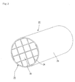
- the shape thereof is not particularly limited as long as it is a column shape and, for example, any optional shape such as a cylinderical shape, an elliptical column shape, a rectangular column shape and the like may be used. In general, as shown in Fig. 1 , those having a cylinderical shape are often used.
- a columnar body is desirably formed by combining a plurality of rectangular columnar porous ceramic members through sealingmaterial layers , each of the rectangular columnar porous ceramic members having a plurality of through holes that are placed in parallel with one another in the length direction with partition wall interposed therebetween.
- Fig. 2 is a perspective view that schematically shows another example of the honeycomb filter of the present invention
- Fig. 3(a) is a perspective view that schematically shows one example of porous ceramic members that constitute the honeycomb filter shown in Fig. 2
- Fig. 3 (b) is a cross-sectional view taken along line B-B of Fig. 3(a) .
- each of the porous ceramic members 30 has a structure in that a number of through holes 31 are placed in parallel with one another in the length direction so that partition wall 33 that separates the through holes 31 from each other functions as filters.
- each of the through holes 31 formed in the porous ceramic member 30 has either of its ends on the inlet-side or outlet-side of exhaust gases sealed with a plug 32; thus, exhaust gases that have entered one of the through holes 31 are allowed to flow out of another through hole 31 after having always passed through the partition wall 33 that separates the corresponding through holes 31 from each other.
- the sealing material layer 26, which is formed on the circumference of the ceramic block 25, is provided so as to prevent exhaust gases from leaking through the peripheral portion of each ceramic block 25 when the honeycomb filter 20 is installed in an exhaust passage of an internal combustion engine.
- arrows indicate flows of exhaust gases.
- the honeycomb filter 20 having the above-mentioned structure is installed in the exhaust passage in an internal combustion engine so that particulates in the exhaust gases discharged from the internal combustion engine are captured by the partition wall 33 when passing through the honeycomb filter 20; thus, the exhaust gases are purified.
- honeycomb filter 20 of this type has superior heat resistance and provides easy recycling processes and the like, it has been applied to various large-size vehicles and vehicles with diesel engines.
- the bending strength thereof is designated as F ⁇ '
- the length of the plug 32 being designated as L'
- the bending strength F ⁇ ' of the honeycomb filter 20 and the length L' of the plug 32 satisfy the following relationship: F ⁇ ' ⁇ L' ⁇ 30.
- the bending strength F ⁇ ' of the honeycomb filter 20 of the present invention corresponds to bending strength of the porous ceramic member that constitutes the honeycomb filter 20 of the present invention, and this bending strength F ⁇ ' is normally measured by carrying out three-point bending tests by the use of a rectangular columnar porous ceramic member 30 in accordance with JIS R 1601, and the bending strength is calculated baseduponthebreakingload, the sizeof the sample, the secondary moment of the honeycomb cross-section and the span-to-span distance.
- the material for the porous ceramic member 30 is not particularly limited, and the same materials as the above-mentioned ceramic materials may be used.
- silicon carbide which has great heat resistance, superior mechanical properties and great thermal conductivity, is desirably used.
- the same porosity and average pore diameter as those of the honeycomb filter 10 of the present invention described by using Fig. 1 may be used.
- the particle size of ceramic particles to be used upon manufacturing the porous ceramic members 30 although not particularly limited, those which are less likely to cause shrinkage in the succeeding firingprocess are desirably used, and for example, those particles, prepared by combining 100 parts by weight of particles having an average particle size from 0 .3 to 50 ⁇ m with 5 to 65 parts by weight of particles having an average particle size from 0.1 to 1. 0 ⁇ m, are desirably used.
- those particles prepared by combining 100 parts by weight of particles having an average particle size from 0 .3 to 50 ⁇ m with 5 to 65 parts by weight of particles having an average particle size from 0.1 to 1. 0 ⁇ m, are desirably used.
- ceramic powders having the above-mentioned respective particle sizes at the above-mentioned blending ratio it is possible to provide a porous ceramic member 30.
- a plurality of porous ceramic members 30 of this type are combined with one another through sealing material layers 24 to form a ceramic block 25, and a sealing material layer 26 is also formed on the circumference of the ceramic block 25.
- the sealing material layer is formed between the porous ceramic members 30 as well as on the circumference of the ceramic block 25, and the sealing material layer (sealing material layer 24) formed between the porous ceramic members 30 functions as an adhesive layer for joining the porous ceramic members 30 to one another, while the sealing material layer (sealing material layer 26) formed on the circumference of the ceramic block 25 functions as a sealing member for preventing leak of exhaust gases from the circumference of the ceramic block 25, when the honeycomb filter 20 of the present invention is installed in the exhaust passage of an internal combustion engine.
- sealing material layer (sealingmaterial layer 24 and sealing material layer 26), not particularly limited, for example, a material composed of an inorganic binder, an organic binder, inorganic fibers and inorganic particles may be used.
- the sealing material layer is formed between the porous ceramic members 30 as well as on the circumference of the ceramic block 25; and these sealing material layers (sealing material layer 24 and sealing material layer 26) may be made of the same material or different materials. In the case where the same material is used for the sealing material layers, the blending ratio of the material may be the same or different.
- Examples of the inorganic binder may include silica sol, alumina sol and the like. Each of these may be used alone or two or more kinds of these may be used in combination. Among the inorganic binders, silica sol is more desirably used.
- organic binder examples include polyvinyl alcohol, methyl cellulose, ethyl cellulose, carboxymethyl cellulose and the like. Each of these may be used alone or two or more kinds of these may be used in combination. Among the organic binders, carboxymethyl cellulose is more desirably used.
- the inorganic fibers may include ceramic fibers such as silica-alumina, mullite, alumina, silica and the like. Each of these may be used alone or two or more kinds of these may be used in combination. Among the inorganic fibers, silica-alumina fibers are more desirably used.
- the inorganic particles may include carbides, nitrides and the like, and specific examples thereof may include inorganic powder or whiskers made of silicon carbide, silicon nitride, boron nitride and the like. Each of these may be used alone, or two or more kinds of these may be used in combination. Among the inorganic particles, silicon carbide having superior thermal conductivity is desirably used.
- the ceramic block 25 is formed into a cylinder-shaped; however, not limited to the cylinder-shaped, the ceramic block of the honeycomb filter of the present invention may have any optional shape such as an elliptical column shape, a rectangular column shape and the like.
- the thickness of the sealing material layer 26 formed on the circumference of the ceramic block 25 is desirably set in a range of 0.3 to 1.0 mm.
- the thickness of less than 0.3 mm tends to cause leak of exhaust gases from the peripheral portion of the ceramic block 25 and, in contrast, the thickness exceeding 1.0 mm tends to cause degradation in economical efficiency, although it can sufficiently prevent leak of exhaust gases.
- a catalyst is desirably attached to the honeycomb filter of the present invention.
- the honeycomb filter of the present invention functions as a filter capable of collecting particulates in exhaust gases, and also to function as a catalyst-supporting member for purifying CO, HC, NO x and the like contained in exhaust gases.
- the catalyst is not particularly limited as long as it can purify CO, HC, NO x and the like in exhaust gases, and examples thereof may include noble metals such as platinum, palladium, rhodium and the like.
- noble metals such as platinum, palladium, rhodium and the like.
- an element such as an alkali metal (Group 1 in Element Periodic Table), an alkali earth metal (Group 2 in Element Periodic Table), a rare-earth element (Group 3 in Element Periodic Table) and a transition metal element, may be added thereto.
- the catalyst upon applying the catalyst onto the honeycomb filter of the present invention, it is preferable to apply the catalyst, after the surface thereof has been preliminarily coated with a catalyst supporting film.
- This arrangement makes it possible to increase the specific surface area, to increase the degree of dispersion of the catalyst, and consequently to increase the reactive portion of the catalyst.
- the catalyst supporting film prevents sintering of the catalyst metal, the heat resistance of the catalyst can be improved. In addition, the pressure loss is also lowered.
- a film made of a material such as alumina, zirconia, titania, silica and the like may be used.
- the method for forming the catalyst supporting film although not particularly limited, upon forming, for example, a catalyst supporting film made of alumina, a method in which the filter is immersed in a slurry solution prepared by dispersing ⁇ -Al 2 O 3 powder in a solvent and a sol-gel method may be used.
- the bending strength F ⁇ is desirably measured after the application of the catalyst.
- F ⁇ ⁇ L ⁇ 30 corresponds to the condition used for preventing the honeycomb filter from breaking down, when it is installed in an exhaust gas purifying apparatus and used; therefore, it is desirable to carry out measurements in the state where the honeycomb filter is attached to the exhaust gas purifying apparatus.
- honeycomb filter of the present invention in which the above-mentioned catalyst is supported is allowed to function as a gas purifying apparatus in the same manner as the conventionally known DPFs with catalyst (Diesel Particulate Filter). Therefore, in the following description, the detailed description of the case where the honeycomb filter of the present invention also serves as a catalyst-supporting member will not be given.
- the bending strength F ⁇ of the honeycomb filter and the length L in the length direction of the through hole of the plug satisfy the relationship of F ⁇ ⁇ L ⁇ 30.
- the length L in the length direction of the through hole of the plug is made longer so as to set the product F ⁇ ⁇ L to 30 or more; therefore, the contact area between the wall portion corresponding to the portion in which the plug is inserted and the plug becomes greater, making it possible to improve the adhesion strength.
- the honeycomb filter of the present invention has a structure formed by a sintered body as a whole, as shown in Fig. 1 .
- an extrusion-moldingprocess is carried out by using a raw material paste mainly composed of ceramics as described above, so that a ceramic molded body, which has a shape corresponding to the honeycomb filter 10 as shown in Fig. 1 , is formed.
- the material paste for example, a material, prepared by adding a binder and a dispersant solution to powder made of the above-mentioned ceramics, is proposed.
- the above-mentioned binder is not particularly limited, and examples thereof may include methylcellulose, carboxy methylcellulose, hydroxy ethylcellulose, polyethylene glycol, phenol resins, epoxy resins and the like.
- the blend ratio of the above-mentioned binder is desirably set to about 1 to 10 parts by weight to 100 parts by weight of ceramic powder.
- the dispersant solution is not particularly limited, and examples thereof may include an organic solvent such as benzene and the like; alcohol such as methanol and the like; water and the like.
- These ceramic powder, binder and dispersant solution are mixed by an attritor or the like, and sufficiently kneaded by a kneader or the like, and then extrusion-molded so that the above-mentioned ceramic molded body is formed.
- a molding auxiliary may be added to the above-mentioned material paste, if necessary.
- the molding auxiliary is not particularly limited, and examples thereof may include ethylene glycol, dextrin, fatty acid soap, polyalcohol and the like.
- a pore-forming agent such as balloons that are fine hollow spheres composed of oxide-based ceramics, spherical acrylic particles and graphite may be added to the above-mentioned raw material paste, if necessary.
- the balloons are not particularly limited, and examples thereof may include alumina balloons, glass micro-balloons, shirasu balloons, fly ash balloons (FA balloons), mullite balloons and the like.
- fly ash balloons are more desirably used.
- these factors are desirably adjusted so as to set the bending strength F ⁇ of the honeycomb filter to be manufactured through the post processes in a range from 1 to 60 MPa.
- the resulting honeycomb filter is less likely to be destructed due to exhaust gases flowing into the through holes, and makes it possible to prevent an abrupt increase in the back pressure during a collecting process of particulates.
- the bending strength F ⁇ of the honeycomb filter is a value that is mainly determined by the ceramic material to be used and its porosity, and the porosity of the honeycomb filter can be controlled by adjusting the material to be used in the material paste, the blend ratio and the like.
- the porosity of the honeycomb filter can also be controlled to a certain degree, by adjusting firing conditions and the like of the ceramic molded body.
- the above-mentioned molded body is dried by using a dryer, such as a microwave dryer, a hot-air dryer, a dielectric dryer, a decompression dryer, a vacuum dryer, a freeze dryer or the like, to form a ceramic dried body, and predetermined through holes are then filled with plug paste that forms a plug; thereafter, the above-mentioned through holes are subjected to mouth-sealing processes so as to be sealed.
- a dryer such as a microwave dryer, a hot-air dryer, a dielectric dryer, a decompression dryer, a vacuum dryer, a freeze dryer or the like
- Fig. 4(a) is a cross-sectional view that schematically shows an example of a mouth-sealing apparatus to be used in the above-mentioned mouth-sealing process
- Fig. 4(b) is a partially enlarged cross-sectional view that shows one portion thereof.
- a mouth-sealing apparatus 100 to be used in the mouth-sealing process has a structure in that a pair of tightly-closed plug discharging tanks 110, each of which has a mask 111 that has an opening section 111a having a predetermined pattern and is placed on its side face, are filled with plug paste 120 and disposed so that the two side faces, each having the mask 111, are aligned face to face with each other.
- a ceramic driedbody 40 is securedbetween the plug discharging tanks 110 so that the end face 40a of the ceramic dried body 40 is made in contact with the mask 111 formed on the side face of each of the plug discharging tanks 110.
- the opening section 111a of the mask 111 and the through hole 42 of the ceramic driedbody 40 are positioned so that they are aligned face to face with each other.
- a predetermined pressure is applied to the plug discharging tank 110 by using, for example, a pump such as a mono-pump, so that the plug paste 120 is discharged from the opening section 111a of the mask 111; thus, by injecting the plug paste 120 to the end of the through hole 42 of the ceramic dried body 40, predetermined through holes 42 of the ceramic dried body 40 are filled with the plug paste 120 that forms the plugs.
- the mouth-sealing apparatus to be used in the above-mentioned mouth-sealing process is not limited to the above-mentioned mouth-sealing apparatus 100, for example, another system may be used in which an open-type plug discharging tank in which a stirring member is installed is prepared, and by vertically shifting the stirring member, the plug paste, filled in the plug discharging tank, is allowed to flow so that the plug paste is injected.
- the distance from the plug paste to the end face of the ceramic dried body is properly adjusted such that the bending strength F ⁇ of the honeycomb filter to be manufactured through post processes and the length L of the plug satisfy the relationship of F ⁇ ⁇ L ⁇ 30.
- the plug paste is desirably injected in a range of 0. 5 to 40 mm from the end face of the ceramic dried body.
- the plug paste is not particularly limited and, for example, the same material as the above-mentioned raw material paste may be used, and a material, which is prepared by adding a lubricant, a solvent, a dispersant and a binder to the ceramic powder that is used for the material paste, is desirably used.
- This material makes it possible to prevent the ceramic particles in the plug paste from precipitating in the middle of the mouth-sealing process.
- the ceramic powder is desirably prepared by adding a small amount of fine powder having a smaller average particle size to coarse powder having a greater average particlesize.
- This arrangement allows the fine powder to bond the ceramic particles to each other.
- the lower limit of the average particle size of the coarse powder is desirably set to 5 ⁇ m, more desirably 10 ⁇ m.
- the upper limit of the average particle size of the coarse powder is desirably set to 100 ⁇ m, more desirably 50 ⁇ m.
- the average particle size of the above-mentioned fine powder is desirably set to a submicron level.
- the materials for the lubricant are not particularly limited, and examples thereof may include polyoxyethylene alkyl ether, polyoxypropylene alkyl ether and the like.
- 0.5 to 8 parts by weight of the lubricant of this type is desirably added to 100 parts by weight of the ceramic powder.
- the addition is less than 0.5 parts by weight, the precipitation rate of the ceramic particles in the plug paste becomes greater, causing separation immediately.
- the flow-passage resistance against the plug paste becomes higher, it sometimes becomes difficult to insert the plug paste into the through holes of the ceramic dried body sufficiently.
- shrinkage becomes greater at the time of firing the ceramic dried body, with the result that cracks tend to occur.
- the above-mentioned polyoxyethylene alkyl ether or polyoxypropylene alkyl ether is prepared by addition-polymerizing ethylene oxide or propylene oxide to alcohol, and has a structure in that an alkyl group is bonded to oxygen at one end of polyoxyethylene (polyoxypropylene).
- an alkyl group is bonded to oxygen at one end of polyoxyethylene (polyoxypropylene).
- the alkyl group may be a straight-chain structure or may have a side-chain structure.
- polyoxyethylene alkyl ether and polyoxypropylene alkyl ether may have a structure in that an alkyl group is bonded to a block copolymer consisting of polyoxyethylene and polyoxypropylene.
- the solvent is not particularly limited, and example thereof may include diethylene glycol mono-2-ethylhexyl ether and the like.
- the dispersant is not particularly limited and, an example thereof may include a surfactant made of phosphate.
- the phosphate may include phosphate of polyoxyethylene alkyl ether, phosphate of polyoxyethylene alkyl phenyl ether, alkyl phosphate and the like.
- 0.1 to 5 parts by weight of the dispersant of this type is desirably added to 100 parts by weight of ceramic powder.
- the amount of addition of less than 0.1 part by weight tends to fail to evenly disperse ceramic particles in the plug paste, while the amount of addition exceeding 5 parts by weight causes a reduction in the density of the plug paste to cause a greater amount of shrinkage at the time of firing, with the result that cracks tend to occur.
- the above-mentioned binder is not particularly limited, and examples thereof may include (meth)acrylate ester-based compounds, such as n-butyl (meth)acrylate, n-pentyl (meth)acrylate and n-hexyl (meth)acrylate.
- 1 to 10 parts by weight of the binder of this type is desirably added to 100 parts by weight of ceramic powder.
- the amount of addition of less than 1 part by weight tends to cause a failure in sufficiently maintaining an adhesion strength between the ceramic particle and the other adhesives.
- the amount of addition exceeding 10 parts by weight causes an excessive increase in the amount of the binder and the subsequent greater amount of shrinkage at the time of firing, with the result that cracks and the like tend to occur.
- the ceramic dried body to which the plug paste is injected is subjected to degreasing and firing processes under predetermined conditions, so that a honeycomb filter that is made of porous ceramics and is constituted by a single sintered body as a whole is manufactured.
- the honeycomb filter of the present invention has a structure, as shown in Fig. 2 , in that a plurality of porous ceramic members are combined with one another through sealing material layers, first, an extrusion-molding process is carried out by using the raw material paste mainly composed of ceramics so that a raw formed body having a shape as shown by a porous ceramic member 30 of Fig. 3 is manufactured.
- the same raw material paste as described in the honeycomb filter constituted by a single sintered body may be used; and with respect to the blend ratio, the same blend ratio as that of the honeycomb filter constituted by a single sintered body or a different blend ratio may be used.
- the above-mentioned molded body is dried by using a microwave dryer or the like to form a dried body, and predetermined through holes are then filled with plug paste that forms a plug; thereafter, the above-mentioned through holes are subjected to mouth-sealing processes so as to be sealed.
- the above-mentioned dried body that has been subjected to the mouth-sealing processes is subjected to degreasing and firing processesunder predetermined conditions, so that a porous ceramic member having a structure in that a plurality of through holes are placed in parallel with one another in the length direction with partition wall interposed therebetween is manufactured.
- porous ceramic members 30 are placed on a base 80 the upper portion of which is designed to have a V-shape in its cross-section so as to allow the porous ceramic members 30 to be stacked thereon in a tilted manner, and sealing material paste to form a sealing material layer 24 is then applied onto two side faces 30a and 30b facing upward with an even thickness to form a sealing material paste layer 81; thereafter, a laminating process for forming another porous ceramic member 30 on this sealing material paste layer 81 is successively repeated, so that a rectangular columnar laminated body 30 having a predetermined size is manufactured.
- a triangular columnar porous ceramic member 30c which is formed by cutting a quadrangular columnar porous ceramic member 30 into two, is bonded to a resin member 82 having the same shape as the triangular columnar porous ceramic member 30c by using a both-sided tape with easy peelability to prepare a corner member, and these corner members are used for the four corners of the laminated body, and after the lamination processes of the porous ceramic members 30, all the resin members 82 forming the four corners of the laminated body of the rectangular columnar ceramic member 30 are removed; thus, a laminated body of the rectangular columnar porous ceramic member 30 is allowed to have a polygonal column-shape in its cross section. With this arrangement, it is possible to reduce the quantity of a waste corresponding to porous ceramic members to be disposed of, after the formation of the ceramic block 25 by cutting the peripheral portion of the laminated body of the rectangular column
- a method for manufacturing the laminated body of the porous ceramic member 30 having a polygonal column-shape in its cross section except for the method shown in Fig. 5 for example, a method in which the porous ceramic members to be located on four corners are omitted and a method in which porous ceramic members having a triangular shape are combined with one another may be used, in accordance with the shape of a honey comb filter to be manufactured.
- a laminated body of a quadrangular columnar ceramic member 30 may of course be manufactured.
- the same materials as described in the honeycomb filter of the present invention may be used; therefore, the description thereof will not be given.
- this porous ceramic member 30 is heated so that the sealing material paste layer 81 is dried and solidified to form a sealing material layer 24, and the peripheral portion of this is then cut into a shape as shown in Fig. 2 by using, for example, a diamond cutter so that a ceramic block 25 is manufactured.
- a sealing material layer 26 is formed on the circumference of the ceramic block 25 by using the sealing material paste, so that a honeycomb filter having a structure in that a plurality of porous ceramic members are combined with one another through sealing material layers is manufactured.
- Each of the honeycomb filters manufactured in this manner has a column shape, and also has a structure in that a number of through holes are placed in parallel with one another with partition wall interposed therebetween.
- the wall portion separating a number of through holes from each other functions as filters for collecting particles as a whole; in contrast, in the case where the honeycomb filter has a structure in that a plurality of porous ceramic members are combined with one another through sealing material layers, since the wall portion separating a number of through holes is constituted by a partition wall forming the porous ceramic member and a sealing material layer used for combining the porous ceramic members as shown in Fig. 2 , one portion thereof, that is, the partition wall portion that is not made in contact with the sealing material layer of the porous ceramic member is allowed to function as the filter for collecting particles.
- the honeycomb filter of the present invention is placed and used in an exhaust gas purifying apparatus to be installed in an exhaust passage of an internal combustion engine such as an engine.
- an exhaust gas purifying apparatus such as an engine.
- the honeycomb filter of the present invention with respect to the recycling method for removing fine particles that have been collected and accumulated, for example, a method in which a back-washing process is carried out by utilizing gas flows and a method in which exhaust gases are heated and directed to flow therein are desirably used.
- Fig. 6 is a cross-sectional view that schematically shows one example of an exhaust gas purifying apparatus in which the honeycomb filter of the present invention is installed.
- the method in which exhaust gases are heated and directed to flow therein is used as the recycling method for removing fine particles that have been collected and accumulated.
- an exhaust gas purifying apparatus 600 is mainly constituted by a honeycomb filter 60 of the present invention, a casing 630 that covers the periphery of the honeycomb filter 60, a holding sealing material 620 placed between the honeycomb filter 60 and the casing 630, and a heating means 610 provided on the exhaust gas inlet side of the honeycomb filter 60, and an introduction pipe 640, coupled to an internal combustion engine such an engine or the like, is connected to one end on the side to which exhaust gases of the casing 630 are introduced, and a discharging pipe 650, lead to the outside, is connected to the other end of the casing 630.
- arrows indicate flows of the exhaust gases.
- the honeycomb filter 60 may be prepared as the honeycomb filter 10 shown in Fig. 1 , or as the honeycomb filter 20 shown in Fig. 2 .
- exhaust gases discharged from an internal combustion engine such as an engine or the like, are introduced into the casing 630 through the introduction pipe 640, and allowed to pass through a wall portion (partition wall) from the through hole of the honeycomb filter 60 so that, after particulates therein have been collected through this wall portion (partition wall) so that the exhaust gases have been purified, the resulting exhaust gases are discharged outside through the discharging pipe 650.
- exhaust gases heated by the heating means 610, are allowed to flow into the through holes of the honeycomb filter 60, so that the honeycomb filter 60 is heated and the particulates accumulated on the wall portion (partition wall) are burned and removed.
- the material for the holding sealing material 620 is not particularly limited, and examples thereof may include inorganic fibers such as crystalline alumina fibers, alumina-silica fibers, silica fibers and the like, and fibers containing one or more kinds of these inorganic fibers.
- the holding sealing material 620 desirably contains alumina and/or silica. This structure makes it possible to provide superior heat resistance and durability in the holding sealing material 620.
- the holding sealing material 620 desirably contains 50% by weight or more of alumina. This structure makes it possible to provide improved elasticity even under high temperatures in a range from 900 to 950°C, and consequently to enhance the holding strength for the honeycomb filter 60.
- the holding sealing material 620 is subjected to a needle punching process. This arrangement allows the fibers constituting the holding sealing material 620 to entangle with one another to improve elasticity and enhance the holding strength for the honeycomb filter 60.
- any optional shape may be used.
- the following shape is proposed: a convex portion is formed on one side of a base portion having a rectangular shape, with a concave section being formed in the side opposing to the one side, so that when put on the circumference of the honeycomb filter 60, the convex portion and the concave section are just fitted to each other.
- This structure makes the holding sealingmaterial 620 covering the circumference of the honeycomb filter 60 less likely to cause deviations.
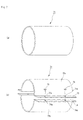
- stainless steel may be used.
- a cylindrical shape as shown by a casing 71 of Fig. 7 (a) may be used, or a two-division shell shape in which a cylinder is divided into two portions in its axis direction as shown by a casing 72 of Fig. 7(b) may be used.
- the size of the casing 630 is appropriately adjusted so that the honeycomb filter 60 is placed therein through the holding sealing material 620.
- the introduction pipe 640 used for introducing exhaust gases is connected to one of the end faces of the casing 630, and the discharging pipe 650 for discharging exhaust gases is connected to the other end face.
- the heating means 610 which is installed so as to heat the gas to be made to flow into the through holes to burn and remove the particulates deposited on the wall portion (partition wall) in the recycling process of the honeycomb filter 60 as described above.
- the heating means 610 is not particularly limited, and examples thereof may include an electric heater, a burner and the like.
- exhaust gases or air and the like are used.
- the exhaust gas purifying apparatus of the present invention may have a system in which the honeycomb filter 60 is heated by the heating means 610 provided on the exhaust gas inlet side of the honeycomb filter 60, or a system in which an oxidizing catalyst is supported on the honeycomb filter, with hydrocarbon being allowed to flow into the honeycomb filter supporting the oxidizing catalyst, so that the honeycomb filter is heated, or a system in which an oxidizing catalyst is placed on the exhaust gas inlet side of the honeycomb filter and the oxidizing catalyst is allowed to generate heat by supplying hydrocarbon to the oxidizing catalyst so that the honeycomb filter is heated.
- the honeycomb filter can be regenerated in parallel with the exhaust gas purifying process, by utilizing a large amount of heat generated during the reaction.
- a holding sealing material with which the circumference of the honeycomb filter of the present invention is coated is prepared.
- an inorganic mat-shaped matter is formed by using inorganic fibers, such as crystalline alumina fibers, alumina-silica fibers and silica fibers, and fibers and the like containing one or more kinds of these inorganic fibers.
- the method for forming the above-mentioned inorganic mat-shaped matter is not particularly limited, and example thereof may include a method in which the above-mentioned fibers and the like are dispersed in a solution containing a bonding agent so that, by utilizing a paper machine and the like for forming paper, an inorganic mat-shaped matter is formed, and other methods.
- the above-mentioned inorganic mat-shaped matter is desirably subj ected to a needle punching process.
- This needle punching process allows the fibers to entangle with one another so that it is possible to prepare a holding sealing material that has high elasticity and is superior in the holding strength for the honeycomb filter.
- a holding sealing material which has the above-mentioned shape in which a convex portion is formedon one side of abase portion having a rectangular shape, with a concave section being formed in the side opposing to the one side, is formed.
- the circumference of the honeycomb filter of the present invention is coated with the above-mentioned holding sealing material so that the holding sealing material is fixed thereon.
- the means for fixing the above-mentioned holding sealing material is not particularly limited, and examples thereof may include means for bonding the holding sealing material by a bonding agent, means for tying it by using a string-shapedmember, and the like. Moreover, the sequence may proceed to the next process with the honeycomb filter being coated with the holding sealing material, without fixing it by using any specific means.
- the above-mentioned string-shaped member may be made of a material to be decomposed through heat. Even if the string-shaped member is decomposed through heat after the honeycomb filter has been placed inside the casing, the holding sealing material is free from peeling since the honeycomb filter has already been installed inside the casing.
- the honeycomb filter that has been subjected to the above-mentioned processes is installed inside the casing.
- the casing is prepared as a cylinder-shaped casing 71 ( Fig. 7(a) ).
- the following method is proposed: a honeycomb filter coated with the holding sealing material is pushed into one of its end faces, and after having been placed at a predetermined position, end faces to be connected to an introduction pipe, piping, a discharging pipe and the like are formed on the two ends of the casing 71.
- the casing 71 may have a cylinderical shape with a bottom face.
- the casing is prepared as a two-division shell-shaped casing 72 as shown in Fig. 7(b) .
- the following method is proposed: after a honeycomb filter has been installed at a predetermined position inside a semicylinder-shaped lower shell 72b, a semicylinder-shaped upper shell 72a is placed on the lower shell 72b so that through holes 73a formed in an upper fixing portion 73 and through holes 74a formed in a lower fixing portion 74 are made coincident with each other. Further, a bolt 75 is inserted through each of the through holes 73a and 74a and fastened with a nut or the like so that the upper shell 72a and the lower shell 72b are secured to each other.
- end faces that have openings to be connected to an introduction pipe, piping, a discharging pipe and the like are formed on two ends of the casing 72.
- the factors such as the thickness of the holding sealing material, the size of the honeycomb filter, the size of the honeycomb filter and the size of the casing 72, need to be adjusted.
- This two-division shell-shaped casing 72 makes it possible to carry out exchanging processes for the honeycomb filter installed inside thereof more easily in comparison with the cylinder-shaped casing 71.
- heating means which is used for heating gases to be allowed to flow into the through holes in the honeycomb filter upon carrying out a recycling process for the honeycomb filter of the present invention, is provided therein.
- the heatingmeans is not particularly limited and, examples thereof may include an electric heater, a burner or the like.
- the above-mentioned heating means is normally provided in the vicinity of the end face on the exhaust gas inlet side of the honeycomb filter installed inside the casing.
- the oxidizing catalyst may be supported on the honeycomb filter of the present invention without installing the above-mentioned heating means, or the oxidizing catalyst may be placed on the exhaust gas inlet side of the honeycomb filter.
- the casing in which the honeycomb filter of the present invention and the heating means are installed is connected to an exhaust gas passage of an internal combustion engine, so that an exhaust gas purifying apparatus in which the honeycomb filter of the present invention is installed can be manufactured.
- the end face of the casing on the side to which the heating means is attached is connected to the introduction pipe that is coupled to the internal combustion engine such as an engine or the like, with the other end face being connected to the discharging pipe connected to the outside.
- Powder of ⁇ -type silicon carbide having an average particle size of 10 ⁇ m (70% by weight) and powder of ⁇ -type silicon carbide having an average particle size of 0. 5 ⁇ m (30% by weight) were wet-mixed, and to 100 parts by weight of the resultingmixture were added and kneaded 10 parts by weight of an organic binder (methyl cellulose), 18 parts by weight of water and 3 parts by weight of a pore-forming agent (spherical acryl particles, average particle size: 10 ⁇ m) to prepare a raw material paste.
- an organic binder methyl cellulose
- a pore-forming agent sintered acryl particles, average particle size: 10 ⁇ m
- the above-mentioned raw material paste was loaded into an extrusion-molding machine, and extruded at an extruding rate of 10 cm/min so that a ceramic formed body having almost the same shape as the porous ceramic member 30 shown in Fig. 3 was formed, and the ceramic formed body was dried by using a microwave dryer to prepare a ceramic dried body.
- powder of ⁇ -type silicon carbide having an average particle size of 10 ⁇ m (60% by weight) and powder of ⁇ -type silicon carbide having an average particle size of 0.5 ⁇ m (40% by weight) were wet-mixed, and to 100 parts by weight of the resultingmixture were added 4 parts by weight of a lubricant made of polyoxyethylene monobutyl ether (trade name: Uniloop, made by NOF Corporation), 11 parts by weight of a solvent made of diethylene glycol mono-2-ethylhexyl ether (trade name: OX-20 , made by Kyowa Hakkou Co., Ltd.), 2 parts by weight of a dispersant made of a phosphate-based compound (trade name: Plysurf, made by Daiichi Kogyo Seiyaku K.K.) and 5 parts by weight of a binder prepared by dissolving n-butyl methacrylate in OX-20 (trade name: Binder D, made by Toei Kasei Co.
- This plug paste was loaded into the plug discharging tank 110 of the mouth-sealing apparatus 100 shown in Fig. 4 , and the ceramic dried body, formed in the above-mentioned process, was moved and secured to a predetermined position; then, the plug discharging tank 110 was moved so that the mask 111 was made in contact with the end face of the ceramic dried body. At this time, the opening section 111a of the mask 111 and the through hole of the ceramic dried body were aligned face to face with each other.
- a predetermined pressure was applied to the plug discharging tank 110 by using a mono-pump, so that the plug paste was discharged from the opening section 111a of the mask 111, and allowed to enter the end portion of the through hole of the ceramic block dried body; thus, a mouth-sealing process was carried out.
- the plug paste was injected in such a manner that the length in the length direction of the through hole of the plug to be formed after a firing process is set to 0.75 mm.
- the ceramic dried body that had been subjected to the mouth-sealing process was again dried by using a microwave drier, the resulting dried body was then degreased at 400°C, and fired at 2200°C in a normal-pressure argon atmosphere for 4 hours to manufacture a porous ceramic member, as shown in Fig. 2 , which was made of a silicon carbide sintered body, and had a size of 33 mm ⁇ 33 mm ⁇ 300 mm, the number of through holes of 31 pcs/cm 2 and a thickness of the partition wall of 0.3 mm.
- porous ceramic members were combined with one another by using a heat-resistant adhesive paste containing 19.6% by weight of alumina fibers having a fiber length of 0.2 mm, 67.8% by weight of silicon carbide particles having an average particle size of 0.6 ⁇ m, 10.1% by weight of silica sol and 2.5% by weight of carboxy methyl cellulose through the method described with reference to Fig. 5 , and then cut by using a diamond cutter; thus, a cylinder-shaped ceramic block having a diameter of 165 mm, as shown in Fig. 2 , was obtained.
- ceramic fibers made of alumina silicate shot content: 3%, fiber length: 0.1 to 100 mm (23.3% by weight) which served as inorganic fibers, silicon carbide powder having an average particle size of 0.3 ⁇ m (30.2% by weight), which served as inorganic particles, silica sol (SiO 2 content in the sol: 30% by weight) (7% by weight), which served as an inorganic binder, carboxymethyl cellulose (0.5% by weight), which served as an organic binder, and water (39% by weight) were mixed and kneaded to prepare a sealing material paste.
- alumina silicate shot content: 3%, fiber length: 0.1 to 100 mm
- a sealing material paste layer having a thickness of 1.0 mm was formed on the circumferential portion of the ceramic block by using the above-mentioned sealing material paste. Further, this sealing material paste layer was dried at 120°C, so that a cylinder-shaped honeycomb filter made of silicon carbide, as shown in Fig. 2 , was manufactured.
- the honeycomb filter thus manufactured had an average pore diameter of 10 ⁇ m with a porosity of 40%, and also had a bending strength of 40 MPa. Moreover, the length of the plug in the length direction of the through hole was 0.75 mm, and the product of the bending strength and the length of the plug of the honeycomb filter was 30.
- Example 2 The same processes as those of Example 1 were carried out except that the plug paste was injected in such a manner that the length of the plug in the length direction of the through hole was set to 3 mm; thus, a honeycomb filter made of silicon carbide was manufactured.
- the product of the bending strength and the length of the plug of the honeycomb filter according to Example 2 was 120.
- Example 2 The same processes as those of Example 1 were carried out except that the plug paste was injected in such a manner that the length of the plug in the length direction of the through hole was set to 5 mm; thus, a honeycomb filter made of silicon carbide was manufactured.
- the product of the bending strength and the length of the plug of the honeycomb filter according to Example 3 was 200.
- Example 2 The same processes as those of Example 1 were carried out except that the plug paste was injected in such a manner that the length of the plug in the length direction of the through hole was set to 0.5 mm; thus, a honeycomb filter made of silicon carbide was manufactured.
- the product of the bending strength and the length of the plug of the honeycomb filter according to Comparative Example 1 was 20.
- Example 2 The same processes as those of Example 1 were carried out except that the plug paste was injected in such a manner that the length of the plug in the length direction of the through hole was set to 6 mm; thus, a honeycomb filter made of silicon carbide was manufactured.
- the product of the bending strength and the length of the plug of the honeycomb filter according to Test Example 1 was 240.
- Powder of ⁇ -type silicon carbide having an average particle size of 10 ⁇ m (80% by weight) and powder of ⁇ -type silicon carbide having an average particle size of 0.5 ⁇ m (20% by weight) were wet-mixed, and to 100 parts by weight of the resulting mixture were added and kneaded 20 parts by weight of an organic binder (methyl cellulose), 30 parts by weight of water and 20 parts by weight of a pore-forming agent (spherical acryl particles, average particle size: 10 ⁇ m) to prepare a raw material paste.
- an organic binder methyl cellulose
- a pore-forming agent sintered acryl particles, average particle size: 10 ⁇ m
- the above-mentioned raw material paste was loaded into an extrusion-molding machine, and extruded at an extruding rate of 10 cm/min to prepare a ceramic formed body, and this ceramic formed body was dried by using a microwave dryer, so that a ceramic dried body having almost the same shape as the porous ceramic member 30 shown in Fig. 3 was formed.
- plug paste was prepared by carrying out the same processes as those of Example 1, and the above-mentioned ceramic dried body was subjected to a mouth-sealing process. At this time, the plug paste was injected in such a manner that the length in the length direction of the through hole of the plug to be formed after a firing process was set to 4.3 mm.
- the ceramic dried body having been subjected to the mouth-sealing process was subj ected to degreasing and firing processes under the same conditions as Example 1 so that a porous ceramic member was manufactured.
- the honeycomb filter thus manufactured had an average pore diameter of 10 ⁇ m with a porosity of 60%, and also had a bending strength of 7 MPa. Moreover, the length of the plug in the length direction of the through hole was 4.3 mm, and the product of the bending strength and the length of the plug of the honeycomb filter was 30.1.
- Example 4 The same processes as those of Example 4 were carried out except that the plug paste was injected in such a manner that the length of the plug in the length direction of the through hole was set to 15mm; thus, a honeycomb filter made of silicon carbide was manufactured.
- the product of the bending strength and the length of the plug of the honeycomb filter according to Example 5 was 105.
- Example 4 The same processes as those of Example 4 were carried out except that the plug paste was injected in such a manner that the length of the plug in the length direction of the through hole was set to 28. 5 mm; thus, a honeycomb filter made of silicon carbide was manufactured.
- the product of the bending strength and the length of the plug of the honeycomb filter according to Example 6 was 199.5.
- Example 4 The same processes as those of Example 4 were carried out except that the plug paste was injected in such a manner that the length of the plug in the length direction of the through hole was set to 4 mm; thus, a honeycomb filter made of silicon carbide was manufactured.
- the product of the bending strength and the length of the plug of the honeycomb filter according to Comparative Example 2 was 28.
- Example 4 The same processes as those of Example 4 were carried out except that the plug paste was injected in such a manner that the length of the plug in the length direction of the through hole was set to 30 mm; thus, a honeycomb filter made of silicon carbide was manufactured.
- the product of the bending strength and the length of the plug of the honeycomb filter according to Test Example 2 was 210.
- Powder of ⁇ -type silicon carbide having an average particle size of 10 ⁇ m (70% by weight) and powder of ⁇ -type silicon carbide having an average particle size of 0.5 ⁇ m (30% by weight) were wet-mixed, and to 100 parts by weight of the resulting mixture were added and kneaded 15 parts by weight of an organic binder (methyl cellulose), 22 parts by weight of water and 5 parts by weight of a pore-forming agent (spherical acryl particles, average particle size: 10 ⁇ m) to prepare a raw material paste.
- an organic binder methyl cellulose
- a pore-forming agent sintered acryl particles, average particle size: 10 ⁇ m
- the above-mentioned raw material paste was loaded into an extrusion-molding machine, and extruded at an extruding rate of 10 cm/min to prepare a ceramic formed body, and this ceramic formed body was dried by using a microwave dryer so that a ceramic dried body having almost the same shape as the porous ceramic member 30 shown in Fig. 3 was formed.
- plug paste was prepared by carrying out the same processes as those of Example 1, and the above-mentioned ceramic dried body was subjected to a mouth-sealing process. At this time, the plug paste was injected in such a manner that the length in the length direction of the through hole of the plug to be formed after a firing process was set to 1.5 mm.
- the ceramic dried body having been subjected to the mouth-sealing process was subj ected to degreasing and firing processes under the same conditions as Example 1, so that a porous ceramic member was manufactured.
- the honeycomb filter thus manufactured had an average pore diameter of 10 ⁇ m with a porosity of 50%, and also had a bending strength of 20 MPa. Moreover, the length of the plug in the length direction of the through hole was 1. 5 mm, and the product of the bending strength and the length of the plug of the honeycomb filter was 30.
- Example 7 The same processes as those of Example 7 were carried out except that the plug paste was injected in such a manner that the length of the plug in the length direction of the through hole was set to 6 mm; thus, a honeycomb filter made of silicon carbide was manufactured.
- the product of the bending strength and the length of the plug of the honeycomb filter according to Example 8 was 120.
- Example 7 The same processes as those of Example 7 were carried out except that the plug paste was injected in such a manner that the length of the plug in the length direction of the through hole was set to 10 mm; thus, a honeycomb filter made of silicon carbide was manufactured.
- the product of the bending strength and the length of the plug of the honeycomb filter according to Example 9 was 200.
- Example 7 The same processes as those of Example 7 were carried out except that the plug paste was injected in such a manner that the length of the plug in the length direction of the through hole was set to 1 mm; thus, a honeycomb filter made of silicon carbide was manufactured.
- the product of the bending strength and the length of the plug of the honeycomb filter according to Comparative Example 3 was 20.
- Example 7 The same processes as those of Example 7 were carried out except that the plug paste was injected in such a manner that the length of the plug in the length direction of the through hole was set to 12 mm; thus, a honeycomb filter made of silicon carbide was manufactured.
- the product of the bending strength and the length of the plug of the honeycomb filter according to Test Example 3 was 240.
- Powder of ⁇ -type silicon carbide having an average particle size of 10 ⁇ m (60% by weight) and powder of ⁇ -type silicon carbide having an average particle size of 0.5 ⁇ m (40% by weight) were wet-mixed, and to 100 parts by weight of the resulting mixture were added and kneaded 5 parts by weight of an organic binder (methyl cellulose) and 10 parts by weight of water to prepare a raw material paste.
- an organic binder methyl cellulose
- the above-mentioned raw material paste was loaded into an extrusion-molding machine, and extruded at an extruding rate of 10 cm/min to prepare a ceramic formed body, and this ceramic formed body was dried by using a microwave dryer so that a ceramic dried body having almost the same shape as the porous ceramic member 30 shown in Fig. 3 was formed.
- plug paste was prepared by carrying out the same processes as those of Example 1, and the above-mentioned ceramic dried body was subjected to a mouth-sealing process. At this time, the plug paste was injected in such a manner that the length in the length direction of the through hole of the plug to be formed after a firing process was set to 0.5 mm.
- the ceramic dried body having been subjected to the mouth-sealing process was subjected to degreasing and firing processes under the same conditions as Example 1 so that a porous ceramic member was manufactured.
- the honeycomb filter thus manufactured had an average pore diameter of 10 ⁇ m with a porosity of 30%, and also had a bending strength of 60 MPa. Moreover, the length of the plug in the length direction of the through hole was 0. 5 mm, and the product of the bending strength and the length of the plug of the honeycomb filter was 30.
- Example 10 The same processes as those of Example 10 were carried out except that the plug paste was injected in such a manner that the length of the plug in the length direction of the through hole was set to 2 mm; thus, a honeycomb filter made of silicon carbide was manufactured.
- the product of the bending strength and the length of the plug of the honeycomb filter according to Example 11 was 120.
- Example 10 The same processes as those of Example 10 were carried out except that the plug paste was injected in such a manner that the length of the plug in the length direction of the through hole was set to 3.3 mm; thus, a honeycomb filter made of silicon carbide was manufactured.
- the product of the bending strength and the length of the plug of the honeycomb filter according to Example 12 was 198.
- Example 10 The same processes as those of Example 10 were carried out except that the plug paste was injected in such a manner that the length of the plug in the length direction of the through hole was set to 0.3 mm; thus, a honeycomb filter made of silicon carbide was manufactured.
- the product of the bending strength and the length of the plug of the honeycomb filter according to Comparative Example 4 was 18.
- Example 10 The same processes as those of Example 10 were carried out except that the plug paste was injected in such a manner that the length of the plug in the length direction of the through hole was set to 4 mm; thus, a honeycomb filter made of silicon carbide was manufactured.
- the product of the bending strength and the length of the plug of the honeycomb filter according to Test Example 4 was 240.
- the above-mentioned raw material paste was loaded into an extrusion-molding machine, and extruded at an extruding rate of 10 cm/min, so that a ceramic formed body having almost the same shape as the honeycomb filter 10 shown in Fig. 1 was formed, and the ceramic formed body was dried by using a microwave dryer to prepare a ceramic dried body.
- talc having an average particle size of 10 ⁇ m (40 parts by weight), kaolin having an average particle size of 9 ⁇ m (10 parts by weight), alumina having an average particle size of 9.5 ⁇ m (17 parts by weight), aluminum hydroxide having an average particle size of 5 ⁇ m (16 parts by weight), silica having an average particle size of 10 ⁇ m (15 parts by weight), a lubricant made of polyoxyethylene monobutyl ether (trade name: Uniloop, made by NOF Corporation) (4 parts by weight), a solvent made of diethylene glycol mono-2-ethylhexyl ether (trade name: OX-20, made by Kyowa Hakkou Co., Ltd.
- a dispersant made of a phosphate-based compound (trade name: Plysurf, made by Daiichi Kogyo Seiyaku K.K.) (2 parts by weight) and a binder prepared by dissolving n-butyl methacrylate in OX-20 (tradename: Binder D, made by Toei Kasei Co. , Ltd.) (5 parts by weight) were blended and evenly mixed; thus, plug paste was prepared.
- Example 2 The same processes as those of Example 1 were carried out by using this plug paste so that the ceramic dried body was subjected to a mouth-sealing process.
- the plug paste was injected in such a manner that the length of the plug to be formed after a firing process is set to 7.5 mm.
- the ceramic dried body that had been subjected to the mouth-sealing process was again dried by using a microwave drier, and the resulting dried body was then degreased at 400°C, and fired at 1400°C in a normal-pressure argon atmosphere for 3 hours to manufacture a cylinder-shaped honeycomb filter made of cordierite having a diameter of 165 mm with a width of 300 mm, as shown in Fig. 1 .
- the honeycomb filter thus manufactured had a porosity of 60% and a bending strength of 4 MPa. Moreover, the length of the plug in the length direction of the through hole was 7.5 mm, and the product of the bending strength and the length of the plug of the honeycomb filter was 30.
- Example 13 The same processes as those of Example 13 were carried out except that the plug paste was injected in such a manner that the length of the plug in the length direction of the through hole was set to 20 mm; thus, a honeycomb filter made of cordierite was manufactured.
- the product of the bending strength and the length of the plug of the honeycomb filter according to Example 14 was 80.
- Example 13 The same processes as those of Example 13 were carried out except that the plug paste was injected in such a manner that the length of the plug in the length direction of the through hole was set to 50 mm; thus, a honeycomb filter made of cordierite was manufactured.
- the product of the bending strength and the length of the plug of the honeycomb filter according to Example 15 was 200.
- Example 13 The same processes as those of Example 13 were carried out except that the plug paste was injected in such a manner that the length of the plug in the length direction of the through hole was set to 7 mm; thus, a honeycomb filter made of cordierite was manufactured.
- the product of the bending strength and the length of the plug of the honeycomb filter according to Comparative Example 5 was 28.
- Example 13 The same processes as those of Example 13 were carried out except that the plug paste was injected in such a manner that the length of the plug in the length direction of the through hole was set to 60 mm; thus, a honeycomb filter made of cordierite was manufactured.
- the product of the bending strength and the length of the plug of the honeycomb filter according to Test Example 5 was 240.
- Talc having an average particle size of 10 ⁇ m (40 parts by weight), kaolin having an average particle size of 9 ⁇ m (10 parts by weight), alumina having an average particle size of 9.5 ⁇ m (17 parts by weight), aluminum hydroxide having an average particle size of 5 ⁇ m (16 parts by weight), silica having an average particle size of 10 ⁇ m (15 parts by weight), graphite having an average particle size of 10 ⁇ m (3 parts by weight), a molding auxiliary (ethylene glycol) (10 parts by weight) and water (18 parts by weight) were mixed and kneaded to prepare a raw material paste.
- kaolin having an average particle size of 9 ⁇ m (10 parts by weight)
- alumina having an average particle size of 9.5 ⁇ m (17 parts by weight
- aluminum hydroxide having an average particle size of 5 ⁇ m (16 parts by weight
- silica having an average particle size of 10 ⁇ m (15 parts by weight)
- graphite having an average particle size of 10 ⁇ m (3 parts by weight)
- the above-mentioned material paste was loaded into an extrusion-molding machine, and extruded at an extruding rate of 10 cm/min to prepare a ceramic formed body, and this ceramic formed body was dried by using a microwave dryer, so that a ceramic dried body having almost the same shape as the porous ceramic member 10 shown in Fig. 1 was formed.
- plug paste was prepared by carrying out the same processes as those of Example 13, and the above-mentioned ceramic dried body was subjected to a mouth-sealing process. At this time, the plug paste was injected in such a manner that the length in the length direction of the through hole of the plug to be formed after a firing process was set to 3.75 mm.
- the ceramic dried body having been subjected to the mouth-sealing process was subjected to degreasing and firing processes under the same conditions as Example 13, so that a cylinder-shaped honeycomb filter made of cordierite, as shown in Fig. 1 , was manufactured.
- the honeycomb filter thus manufactured had a porosity of 40% and a bending strength of 8 MPa. Moreover, the length of the plug in the length direction of the through hole was 3.75 mm, and the product of the bending strength and the length of the plug of the honeycomb filter was 30.
- Example 16 The same processes as those of Example 16 were carried out except that the plug paste was injected in such a manner that the length of the plug in the length direction of the through hole was set to 12 mm; thus, a honeycomb filter made of cordierite was manufactured.
- the product of the bending strength and the length of the plug of the honeycomb filter according to Example 17 was 96.
- Example 16 The same processes as those of Example 16 were carried out except that the plug paste was injected in such a manner that the length of the plug in the length direction of the through hole was set to 25 mm; thus, a honeycomb filter made of cordierite was manufactured.
- the product of the bending strength and the length of the plug of the honeycomb filter according to Example 18 was 200.
- Example 16 The same processes as those of Example 16 were carried out except that the plug paste was injected in such a manner that the length of the plug in the length direction of the through hole was set to 3 mm; thus, a honeycomb filter made of cordierite was manufactured.
- the product of the bending strength and the length of the plug of the honeycomb filter according to Comparative Example 6 was 24.
- Example 16 The same processes as those of Example 16 were carried out except that the plug paste was injected in such a manner that the length of the plug in the length direction of the through hole was set to 28 mm; thus, a honeycomb filter made of cordierite was manufactured.
- the product of the bending strength and the length of the plug of the honeycomb filter according to Test Example 6 was 224.
- Talc having an average particle size of 10 ⁇ m (40 parts by weight), kaolin having an average particle size of 9 ⁇ m (10 parts by weight), alumina having an average particle size of 9.5 ⁇ m (17 parts by weight), aluminum hydroxide having an average particle size of 5 ⁇ m (16 parts by weight), silica having an average particle size of 10 ⁇ m (15 parts by weight), graphite having an average particle size of 10 ⁇ m (25 parts by weight), a molding auxiliary (ethylene glycol) (15 parts by weight) and water (20 parts by weight) were mixed and kneaded to prepare a material paste.
- kaolin having an average particle size of 9 ⁇ m (10 parts by weight)
- alumina having an average particle size of 9.5 ⁇ m (17 parts by weight
- aluminum hydroxide having an average particle size of 5 ⁇ m (16 parts by weight
- silica having an average particle size of 10 ⁇ m (15 parts by weight)
- graphite having an average particle size of 10 ⁇ m (25 parts by weight)
- the above-mentioned material paste was loaded into an extrusion-molding machine, and extruded at an extruding rate of 10 cm/min to prepare a ceramic formed body having almost the same shape as the honeycomb filter 10 shown in Fig. 1 , and this ceramic formed body was dried by using a microwave dryer to prepare a ceramic dried body.
- plug paste was prepared by carrying out the same processes as those of Example 13, and the above-mentioned ceramic dried body was subjected to a mouth-sealing process. At this time, the plug paste was injected in such a manner that the length in the length direction of the through hole of the plug to be formed after a firing process was set to 6.3 mm.
- the ceramic dried body having been subjected to the mouth-sealing process was subj ected to degreasing and firing processes under the same conditions as Example 13 so that a cylinder-shaped honeycomb filter made of cordierite, as shown in Fig. 1 , was manufactured.
- the honeycomb filter thus manufactured had a porosity of 55% and a bending strength of 4.7 MPa. Moreover, the length of the plug in the length direction of the through hole was 6.3 mm, and the product of the bending strength and the length of the plug of the honeycomb filter was 30.
- Example 19 The same processes as those of Example 19 were carried out except that the plug paste was injected in such a manner that the length of the plug in the length direction of the through hole was set to 23 mm; thus, a honeycomb filter made of cordierite was manufactured.
- the product of the bending strength and the length of the plug of the honeycomb filter according to Example 20 was 108.
- Example 19 The same processes as those of Example 19 were carried out except that the plug paste was injected in such a manner that the length of the plug in the length direction of the through hole was set to 42.6 mm; thus, a honeycomb filtermade of cordierite was manufactured.
- the product of the bending strength and the length of the plug of the honeycomb filter according to Example 21 was 200.
- Example 19 The same processes as those of Example 19 were carried out except that the plug paste was injected in such a manner that the length of the plug in the length direction of the through hole was set to 6 mm; thus, a honeycomb filter made of cordierite was manufactured.
- the product of the bending strength and the length of the plug of the honeycomb filter according to Comparative Example 7 was 28.
- Example 19 The same processes as those of Example 19 were carried out except that the plug paste was injected in such a manner that the length of the plug in the length direction of the through hole was set to 43 mm; thus, a honeycomb filter made of cordierite was manufactured.
- the product of the bending strength and the length of the plug of the honeycomb filter according to Test Example 7 was 202.
- Talc having an average particle size of 10 ⁇ m (40 parts by weight), kaolin having an average particle size of 9 ⁇ m (10 parts by weight), alumina having an average particle size of 9.5 ⁇ m (17 parts by weight), aluminum hydroxide having an average particle size of 5 ⁇ m (16 parts by weight), silica having an average particle size of 10 ⁇ m (15 parts by weight), graphite having an average particle size of 10 ⁇ m (40 parts by weight), a molding auxiliary (ethylene glycol) (25 parts by weight) and water (30 parts by weight) were mixed and kneaded to prepare a raw material paste.
- kaolin having an average particle size of 9 ⁇ m (10 parts by weight)
- alumina having an average particle size of 9.5 ⁇ m (17 parts by weight
- aluminum hydroxide having an average particle size of 5 ⁇ m (16 parts by weight
- silica having an average particle size of 10 ⁇ m (15 parts by weight)
- graphite having an average particle size of 10 ⁇ m (40 parts by weight)
- water
- the above-mentioned raw material paste was loaded into an extrusion-molding machine, and extruded at an extruding rate of 10 cm/min to prepare a ceramic formed body having almost the same shape as the honeycomb filter 10 shown in Fig. 1 , and this ceramic formed body was dried by using a microwave dryer to form a ceramic dried body.
- plug paste was prepared by carrying out the same processes as those of Example 13, and the above-mentioned ceramic dried body was subjected to a mouth-sealing process. At this time, the plug paste was injected in such a manner that the length in the length direction of the through hole of the plug to be formed after a firing process was set to 10 mm.
- the ceramic dried body having been subjected to the mouth-sealing process was subj ected to degreasing and firing processes under the same conditions as Example 13 so that a cylinder-shaped honeycomb filter made of cordierite, as shown in Fig. 1 , was manufactured.
- the honeycomb filter thus manufactured had a porosity of 70% and a bending strength of 3.0 MPa. Moreover, the length of the plug in the length direction of the through hole was 10 mm, and the product of the bending strength and the length of the plug of the honeycomb filter was 30.
- Example 22 The same processes as those of Example 22 were carried out except that the plug paste was injected in such a manner that the length of the plug in the length direction of the through hole was set to 38 mm; thus, a honeycomb filter made of cordierite was manufactured.
- the product of the bending strength and the length of the plug of the honeycomb filter according to Example 23 was 114.
- Example 22 The same processes as those of Example 22 were carried out except that the plug paste was injected in such a manner that the length of the plug in the length direction of the through hole was set to 66 mm; thus, a honeycomb filter made of cordierite was manufactured.
- the product of the bending strength and the length of the plug of the honeycomb filter according to Example 24 was 198.
- Example 22 The same processes as those of Example 22 were carried out except that the plug paste was injected in such a manner that the length of the plug in the length direction of the through hole was set to 9 mm; thus, a honeycomb filter made of cordierite was manufactured.
- the product of the bending strength and the length of the plug of the honeycomb filter according to Comparative Example 8 was 27.
- Example 22 The same processes as those of Example 22 were carried out except that the plug paste was injected in such a manner that the length of the plug in the length direction of the through hole was set to 70 mm; thus, a honeycomb filter made of cordierite was manufactured.
- the product of the bending strength and the length of the plug of the honeycomb filter according to Test Example 8 was 210.
- each of the honeycomb filters according to the respective examples, comparative examples and test examples was installed in an exhaust gas purifying apparatus, as shown in Fig. 6 , that is disposed in an exhaust passage of an engine, and the engine was driven at the number of revolutions of 3000 min -1 with a torque of 50 Nm for 10 hours so that an exhaust gas purifying process was carried out.
- each of the honeycomb filters was taken out and visually observed as to whether or not any cracks were present.
- the honeycomb filters that had no cracks after the endurance test were further subjected to heat cycle tests in which the above-mentioned endurance tests were repeated 300 times, and each of the honeycomb filters was taken out and visually observed as to whether or not any cracks were present.
- each of the honeycomb filters according to Examples 1 to 24 had a low value of initial back pressure in a range from 7 to 13.2 kPa, and had no cracks caused by an impact due to a pressure of exhaust gases entering the inside of the through hole, with a back pressure after the endurance test being not so high. Moreover, even after the heat recycling tests, no cracks were observed.
- each of the honeycomb filters according to Comparative Examples 1 to 8 had a comparatively low initial back pressure in a range from 5 to 10 kPa; however, cracks, which were caused by an impact due to a pressure of exhaust gases entering the inside of the through hole, occurred centered on the wall portion (partition wall) on the exhaust gas outlet side, which had the plug inserted therein, and received the highest impact.
- honeycomb filters according to text Examples 1 to 8 had a high value in the initial pressure in a range from 10 to 18 kPa, and had no cracks, which were caused by an impact due to a pressure of exhaust gases entering the inside of the through hole observed, observed; however, the back pressure after the endurance test became extremely high, and cracks occurred after the heat cycle tests.
- the honeycomb filters according to Examples 1 to 24 are less likely to cause occurrence of cracks due to an impact from a pressure of exhaust gases discharged from the engine, and superior in the durability, and make it possible to prevent the back pressure from becoming high abruptly upon collecting particulates; therefore, it becomes possible to eliminate the necessity of carrying out the recycling process on the honeycomb filter frequently, and consequently to provide sufficient functions as the filter.
- each of the honeycomb filters according to Comparative Examples 1 to 8 was more likely to cause: cracks on the wall portion (partition wall) in which the plug is inserted; and coming-off of the plug, resulting in degradation in the durability. Moreover, even in the case of the honeycomb filter having no coming-off of the plug, exhaust gases tend to leak through cracks, failing to sufficiently function as the filter.
- honeycomb filters according to Test Examples 1 to 8 are less likely to cause immediate occurrence of cracks due to a pressure of exhaust gases discharged from the engine; however, since the filtering capable region becomes smaller than that of the honeycomb filters according to Examples 1 to 18, the back pressure becomes abruptly higher upon collecting particulates, resulting in cracks during a long-term use.
- the results obtained from Examples 19 to 21 as well as Comparative Example 7 show that a honeycomb filter, made of cordierite having a porosity of 55%, has a bending strength of 4.7 MPa, and needs to have a plug having a length of 6.3 mm or more in order to prevent occurrence of cracks during the endurance tests.
- the results of Examples 13 to 15 as well as Comparative Example 5 show that a honeycomb filter, made of cordierite having a porosity of 60%, has a bending strength of 4 MPa, and needs to have a plug having a length of 7.5 mm or more in order to prevent occurrence of cracks during the endurance tests.
- Examples 22 to 24 as well as Comparative Example 8 show that a honeycomb filter, made of cordierite having a porosity of 70%, has a bending strength of 4 MPa, and needs to have a plug having a length of 10 mm or more in order to prevent occurrence of cracks during the endurance tests.
- honeycomb filter disclosed in the embodiment of JP Kokai 2003-3823 , since the honeycomb filter is made of cordierite, and has a porosity in a range of 55 to 70% in the partition wall, with the length of the plug being set in a range from 2 to 6 mm; the length of the plug is too short, thus it is assumed that cracks tend to occur during the endurance tests.
- Fig. 8(a) is a graph that shows a relationship between the bending strength of the honeycomb filter and the length of the plug, according to each of Examples 1 to 24; and Fig. 8 (b) is a graph that shows a relationship between the bending strength of the honeycomb filter and the length of the plug, according to Comparative Examples 1 to 8 as well as Test Examples of 1 to 8.
- the curve on the lower side represents a curve in which the product of the bending strength F ⁇ of the honeycomb filter and the length L of the plug is set to 30, while the curve on the upper side represents a curve in which the product of the bending strength F ⁇ of the honeycomb filter and the length L of the plug is set to 200.
- each of the values of the product between the bending strength F ⁇ of the honeycomb filter and the length L of the plug in Examples 1 to 24 is located between the upper and lower curves, and in contrast, as shown in Fig. 8(b) , each of the values of the product between the bending strength F ⁇ of the honeycomb filter and the length L of the plug in Comparative Examples 1 to 8 is located below the curve on the lower side. Moreover, each of the values of the product between the bending strength F ⁇ of the honeycomb filter and the length L of the plug in Test Examples 1 to 8 is located above the curve on the upper side.
- the honeycomb filter for purifying exhaust gases according to the present invention has the above-mentioned arrangement, it is free from occurrence of cracks and coming-off of plugs and is superior in durability upon its use.
Abstract
a bending strength Fα (MPa) of the honeycomb filter for purifying exhaust gases and a length L (mm) of the plug in the length direction of the through hole satisfy the relationship of Fα × L ≥ 30.
Description
- This application claims benefit of priority to Japanese Patent Application No.
2002-108538, filed on April 10, 2002 - The present invention relates to a honeycomb filter for purifying exhaust gases that is used as a filter for removing particulates and the like contained in exhaust gases discharged from an internal combustion engine such as a diesel engine.
- In recent years, particulates (fine particles) contained in exhaust gases discharged from internal combustion engines of vehicles such as buses, trucks and the like and construction machines have raised serious problems as these particles are harmful to the environment and the human body.
- There have been proposed various ceramic filters which allow exhaust gases to pass through porous ceramics and collect particulates in the exhaust gases to purify the exhaust gases.
- Conventionally, in the ceramic filter of this type, a number of through holes are placed in parallel with one another in one direction and wall portion that separates the through holes from each other functions as filters.
- In other words, each of the through holes formed in the ceramic filter is sealed with a plug at either of ends of its exhaust gas inlet side or outlet side so as to form a so-called checkered pattern; thus, exhaust gases that have entered one through hole are discharged from another through hole after having always passed through partition wall that separates the through holes from each other. Consequently, when the exhaust gases pass through the partition wall, the particulates are captured by the portion of the partition wall to be purified.
- As such a purifying process for exhaust gases progresses, particulates are gradually accumulated on the partition wall that separates the through holes of the honeycomb filter from each other to cause clogging and the subsequent interruption in gas permeability.
- In order to solve this problem, there has been developed a honeycomb filter of a back-washing system, which, after having collected particulates, forms a gas flow in a direction reversed to the flow-in direction of exhaust gases so as to remove the particulates; however, this system requires a complex structure, and fails to provide a practical system (see
JP Kokai Hei 7-332064 - For this reason, the above-mentioned honeycomb filter needs to be regularly subjected to a recycling process in which the particulates that cause clogging are burned and removed by using heating means such as a heater or the like to regenerate the filter.
- Here, in the conventional honeycomb filter having the above-mentioned structure, the region capable of purifying the exhaust gases (hereinafter, referred to as a filtration capable region) corresponds to the inner wall of the through hole that is opened on the exhaust gas flow-in side. In order to maintain the filtration capable region as wide as possible in the honeycomb filter and also to keep the back pressure upon collection of particulates at a low level, it is profitable to make the length of a plug in the length direction of the through hole as short as possible.
- Moreover, in the case where the porosity of the honeycomb filter is low, the back pressure becomes higher quickly upon collecting the particulates, with the result that the above-mentioned recycling process using the heating means such as a heater or the like needs to be carried out frequently; therefore, an attempt to make the porosity of the honeycomb filter higher has been made conventionally.
- In recent years, another technique has been proposed in which, in place of the above-mentioned recycling process of the honeycomb filter using the heating means such as a heater or the like, by allowing the honeycomb filter to support an oxidizing catalyst in its pores, hydrocarbon contained in exhaust gases that flow into the honeycomb filter is made to react with the oxidizing catalyst, then heat generated through this reaction is utilized for the recycling process. In the honeycomb filter that carries out the recycling process in this manner, it is necessary to increase the porosity thereof, because the oxidizing catalyst is supported on the inside of each pore of the honeycomb filter so that the pore becomes more likely to cause clogging due to particulates, and because the oxidizing catalyst needs to be supported as much as possible in order to generate a large amount of heat, or other reasons
- By increasing the porosity of the honeycomb filter in this manner, it becomes possible to prevent the back pressure from becoming higher, to provide a superior particulate collecting property, and also to allow the filter to support a large amount of oxidizing catalyst.
- However, the increase in the porosity of the honeycomb filter causes a reduction in the strength of the honeycomb filter itself. For this reason, when an exhaust gas purifying apparatus , to which the honeycomb filter is attached, is installed in an exhaust gas passage of an internal combustion engine such as an engine or the like, and actually used, cracks tend to occur in the partition wall due to an impact caused by a pressure and the like from the exhaust gases.
- Moreover, as described above, the plug to be injected into the end of the through hole is formed to have the length in the length direction of the through hole, which is set as short as possible, in order to maintain the filtering capable region as wide as possible; however, the honeycomb filter of this type has a small contact area between the plug and the partition wall, resulting in a reduction in the adhesion strength of the plug to the partition wall (see
JP Kokai 2003-3823 - Here, the portion of the partition wall in which the plug is injected on the outlet side of exhaust gases corresponds to a portion that is to have a highest impact from the pressure and the like from the exhaust gases; consequently, in the case of the honeycomb filter having a reduced bending strength due to the above-mentioned increased porosity, the partition wall in which the plug is injected is more likely to cause: occurrence of cracks due to an impact caused by a pressure and the like from the exhaust gases; and the subsequent coming-off of the plug, resulting in degradation in the durability.
- The present invention is made to solve the above-mentioned problems, and its object is to provide a honeycomb filter for purifying exhaust gases that is free from occurrence of cracks and coming-off of plugs and is superior in durability upon its use.
- The present invention provides a honeycomb filter for purifying exhaust gases which has a structure in which:
- a columnar body made of porous ceramic comprises a number of through holes, the above-mentioned through holes being placed in parallel with one another in the length direction with wall portion interposed therebetween;
- predetermined through holes of the above-mentioned through holes are filled with plugs at one end of the above-mentioned columnar body, while the through holes that have not been filled with the above-mentioned plugs at the above-mentioned one end are filled with plugs at the other end of the above-mentioned columnar body; and
- a part or all of the above-mentioned wall portion functions as a filter for collecting particulates
- a bending strength Fα (MPa) of the above-mentioned honeycomb filter for purifying exhaust gases and a length L (mm) of the above-mentioned plug in the length direction of the through hole satisfy the relationship of Fα × L ≥ 30.
-
-
Fig. 1 (a) is a perspective view that schematically shows one example of a honeycomb filter for purifying exhaust gases of the present invention, andFig. 1(b) is a cross-sectional view taken along line A-A ofFig. 1(a) . -
Fig. 2 is a perspective view that schematically shows another example of the honeycomb filter for purifying exhaust gases of the present invention. -
Fig. 3 (a) is a perspective view that schematically shows a porous ceramic member to be used in the honeycomb filter for purifying exhaust gases of the present invention shown inFig. 2 ; andFig. 3 (b) is a cross-sectional view taken along line B-B ofFig. 3(a) . -
Fig. 4(a) is a cross-sectional view that schematically shows one example of a mouth-sealing apparatus to be used upon manufacturing the honeycomb filter for purifying exhaust gases of the present invention, andFig. 4 (b) is a partially enlarged cross-sectional view of the mouth-sealing apparatus shown inFig. 4 (a) . -
Fig. 5 is a side view that schematically shows a state where the honeycomb filter for purifying exhaust gases of the present invention is manufactured. -
Fig. 6 is a cross-sectional view that schematically shows one example of an exhaust gas purifying apparatus to which the honeycomb filter for purifying exhaust gases of the present invention is attached. -
Fig. 7 (a) is a perspective view that schematically shows one example of a casing to be used in the exhaust gas purifying apparatus shown inFig. 6 , and Fig. (b) is a perspective view that schematically shows one example of another casing. -
Fig. 8(a) is a graph that shows a relationship between the bending strength and the length of the plug of the honeycomb filter according to each example, andFig. 8 (b) is a graph that shows a relationship between the bending strength and the length of the plug of the honeycomb filter according to each comparative example and test example. -
- 10, 20
- honeycomb filter for purifying exhaust gases
- 11, 31
- through hole
- 12, 32
- plug
- 13
- wall portion
- 24
- sealing material layer
- 25
- ceramic block
- 26
- sealing material layer
- 30
- porous ceramic member
- 33
- partition wall
- The present invention provides a honeycomb filter for purifying exhaust gases which has a structure in which:
- a columnar body made of porous ceramic comprises a number of through holes, the above-mentioned through holes being placed in parallel with one another in the length direction with wall portion interposed therebetween;
- predetermined through holes of the above-mentioned through holes are filled with plugs at one end of the above-mentioned columnar body, while the through holes that have not been filled with the above-mentioned plugs at the above-mentioned one end are filled with plugs at the other end of the above-mentioned columnar body; and
- a part or all of the above-mentioned wall portion functions as a filter for collecting particulates
- a bending strength Fα (MPa) of the above-mentioned honeycomb filter for purifying exhaust gases and a length L (mm) of the above-mentioned plug in the length direction of the through hole satisfy the relationship of Fα × L ≥ 30.
- Additionally, in the following description, "the honeycomb filter for purifying exhaust gases of the present invention" is also simply referred to as "the honeycomb filter of the present invention", and "the length of the plug in the length direction of the above-mentioned through hole" is also simply referred to as "the length of the plug".
-
Fig. 1(a) is a perspective view that schematically shows one example of the honeycomb filter of the present invention, andFig. 1(b) is a cross-sectional view taken along line A-A ofFig. 1(a) . - As shown in
Fig. 1(a) , thehoneycomb filter 10 of the present invention is a columnar body made of a single porous ceramic sintered body in which a number of throughholes 11 are placed in parallel with one another in the length direction withwall portion 13 interposed therebetween, and all thewall portion 13 is designed to function as filters for collecting particles. - In other words, as shown in
Fig. 1 (b) , each of the throughholes 11 formed in thehoneycomb filter 10 has either of its ends on the inlet-side or outlet-side of exhaust gases sealed with aplug 12; thus, exhaust gases that have entered one of the throughholes 11 are allowed to flow out of another throughhole 11 after always passing through thewall portion 13 that separates the corresponding throughholes 11 from each other. - Consequently, particulates contained in the exhaust gases that have entered the
honeycomb filter 10 of the present invention are captured by thewall portion 13 when passing through thewall portion 13, so that the exhaust gases are purified. - The
honeycomb filter 10 having the above-mentioned arrangement is disposed in an exhaust gas purifying apparatus and used therein, and the exhaust gas purifying apparatus is installed in an exhaust passage in an internal combustion engine. - It is noted that the exhaust gas purifying apparatus will be described later.
- The
honeycomb filter 10 of the present invention is designed so that the product of the bending strength Fα (MPa) of thehoneycomb filter 10 and the length L (mm) of theplug 12, that is, Fα × L is set to 30 or more. - The bending strength Fα of the
honeycomb filter 10 of the present invention corresponds to bending strength of the porous ceramic material that constitutes thehoneycomb filter 10 of the present invention, and this bending strength Fα is normally measured by the following method: a rectangular columnar sample with a face perpendicular to the length direction of a throughhole 11, that has a size of about 34 (mm) × 34 (mm), as shown inFig. 3(a) , is cut out along the inner walls of the throughhole 11, and three-point bending tests were carried out on this sample in accordance with JIS R 1601, and the bending strength is calculatedbased upon the breaking load, the size of the sample, the secondary moment of the honeycomb cross-section and the span-to-span distance. - In the
honeycomb filter 10 of the present invention, the lower limit of Fα × L is set to 30; therefore, in the case where the porosity of thehoneycomb filter 10 is increased with the result that the bending strength is lowered, that is, Fα becomes smaller, the length L of theplug 12 is made longer in comparison with a honeycomb filter having a greater bending strength. - Consequently, the contact area between the
plug 12 inserted into the end of the throughhole 11 and thewall portion 13 becomes greater, making it possible to improve the adhesion strength between these. Therefore, it becomes possible to prevent: occurrence of cracks at the portion of thewall portion 13 filled with theplug 12; and coming-off of theplug 12 due to exhaust gases that flow into the throughhole 11. - When the product, Fα × L, is less than 30, the bending strength Fα of the
honeycomb filter 10 becomes too small, or the length L of theplug 12 becomes too short. - In the case where the strength Fα is too small, cracks easily occur due to exhaust gases that are flowing into the honeycomb filter of the present invention, failing to use it as the filter for purifying exhaust gases. Further, in the case where the length L is too short, the adhesion strength of the plug injected into the end of the through hole is lowered, causing the pLug to come off due to a thermal impact and the like imposed when exhaust gases flow into the honeycomb filter of the present invention.
- Moreover, in the
honeycomb filter 10 of the present invention, the product, Fα × L, is desirably set to 200 or less. When Fα × L exceeds 200, the bending strength Fα of thehoneycomb filter 10 becomes too great, or the length L of theplug 12 becomes too long. - In the case where the bending strength Fα becomes too great, that is, in the case where the
honeycomb filter 10 having an extremely great bending strength is manufactured, the porosity of thehoneycomb filter 10 becomes too low in some cases, making the back pressure become high immediately, upon collecting particulates; therefore, it is necessary to frequently carry out recycling processes of thehoneycomb filter 10. In the case where the length L of the plug is too long, the filtering capable region for exhaust gases in thehoneycomb filter 10 of the present invention becomes smaller, also making the back pressure become high immediately, upon collecting particulates; therefore, it is necessary to frequently carry out recycling processes of thehoneycomb filter 10. - Moreover, in the case of a honeycomb filter in which Fα × L exceeds 200, the back pressure sometimes rises abruptly in use, causing a destruction of the honeycomb filter and a trouble in an internal combustion engine such as an engine in some cases.
- In the
honeycomb filter 10 of the present invention, not particularly limited, the magnitude of the bending strength Fα of thehoneycomb filter 10 is properly determined depending on the ceramic material to be used and the porosity of thetarget honeycomb filter 10, and is desirably set in a range from 1 to 60 MPa. When Fα is less than 1 MPa, it is necessary to make the length L of the plug extremely longer so as to satisfy the relationship Fα × L ≥ 30, and this makes the filtering capable region of the honeycomb filter smaller, and tends to make the back pressure immediately higher upon collecting particulates; therefore, it is necessary to frequently carry out the recycling process of the honeycomb filter. Moreover, the honeycomb filter tends to be easily broken by an impact caused by a pressure and the like from exhaust gases, and it becomes difficult to manufacture the honeycomb filter having such a low strength in some cases. In contrast, when the Fα exceeds 60 MPa, the porosity of thehoneycomb filter 10 is lowered, resulting in an abrupt increase in the back pressure upon collecting particulates; therefore, it is necessary to frequently carry out the recycling process of the honeycomb filter. - Moreover, in the
honeycomb filter 10 of the present invention, not particularly limited, the length L of theplug 12 is desirably set, for example, in a range from 0.5 to 40 mm. - When L is less than 0.5 mm, the contact area between the
plug 12 inserted into the throughhole 11 of thehoneycomb filter 10 and thewall portion 13 of thehoneycomb filter 10 becomes smaller, and the adhesion strength therebetween is lowered, resulting in: occurrence of cracks at the portion of thewall portion 13 filled with theplug 12; and coming-off of theplug 12 due to an impact of a pressure and the like from incoming exhaust gases. In contrast, when L exceeds 40 mm, the filtering capable region for exhaust gases in thehoneycomb filter 10 becomes too small, resulting in an abrupt increase in the back pressure upon collecting particulates in some cases; therefore, it is necessary to frequently carry out the recycling process of thehoneycomb filter 10. Moreover, in the case of a honeycomb filter of this type, the back pressure sometimes rises abruptly in use, sometimes causing a destruction of the honeycomb filter and a trouble in an internal combustion engine such as an engine. - The
honeycomb filter 10 of the present invention is made of a porous ceramic material. - The ceramic material is not particularly limited, and examples thereof may include oxide ceramics such as cordierite, alumina, silica, mullite and the like; carbide ceramics such as silicon carbide, zirconium carbide, titanium carbide, tantalum carbide, tungsten carbide and the like; and nitride ceramicssuch asaluminum nitride,silicon nitride,boron nitride, titanium nitride and the like. Normally, oxide ceramics such as cordierite and the like are utilized. These materials make it possible to carry out the manufacturing process at low costs, have a comparatively small coefficient of thermal expansion and are less likely to cause oxidation upon their use. Further, silicon-containing ceramics made by blending metallic silicon in the above-mentioned ceramics, and ceramics bonded by silicon and silicate compound may be used.
- Moreover, the porosity of the
honeycomb filter 10 of the present invention is closely related to the strength of thehoneycomb filter 10, and varies depending on the strength; therefore, the porosity, which is set so that the strength is located within the above-mentioned range, is normally set in a range from 30 to 80%. When the porosity is less than 30%, thehoneycomb filter 10 is more likely to cause a clogging, while the porosity exceeding 80% causes degradation in the strength of thehoneycomb filter 10, with the result that it might be easily broken. - Here, the above-mentioned porosity can be measured through known methods, such as a mercury press-in method, Archimedes method and a measuring method using a scanning electronic microscope (SEM).
- The average pore diameter of the porous
ceramic members 10 is desirably set in a range from 5 to 100 µm. The average pore diameter of less than 5 µm tends to cause clogging of particulates easily. In contrast, the average pore diameter exceeding 100 µm tends to cause particulates to pass through the pores, with the result that the particulates cannot be collected, making the members unable to function as a filter. - Moreover, as shown in
Fig. 1(b) , in thehoneycomb filter 10, a number of throughholes 11 used for allowing exhaust gases to flow are arranged in parallel with one another in the length direction withwall portion 13 interposed therebetween, and each of the throughholes 11 has either of its ends on the inlet-side or outlet-side sealed with aplug 12. - The material to be used for forming the
plug 12 is not particularly limited and, for example, the above-mentioned material mainly composed of ceramic is proposed. In particular, the same material as the ceramic material forming thehoneycomb filter 10 is desirably used. Thus, it becomes possible to provide the same thermal expansion coefficient as the honeycomb filter, and consequently to prevent generation of cracks due to temperature changes during use and upon recycling processes. - The size of the
honeycomb filter 10 is not particularly limited, and it is appropriately determined by taking the size of an exhaust gas passage of the internal combustion engine to be used and the like into consideration. - Moreover, the shape thereof is not particularly limited as long as it is a column shape and, for example, any optional shape such as a cylinderical shape, an elliptical column shape, a rectangular column shape and the like may be used. In general, as shown in
Fig. 1 , those having a cylinderical shape are often used. - Furthermore, in the honeycomb filter of the present invention, a columnar body is desirably formed by combining a plurality of rectangular columnar porous ceramic members through sealingmaterial layers , each of the rectangular columnar porous ceramic members having a plurality of through holes that are placed in parallel with one another in the length direction with partition wall interposed therebetween. With this arrangement, since the columnar body is divided into the porous ceramic members, it is possible to reduce a thermal stress exerted on the porous ceramic members upon its use, and consequently to make the honeycomb filter of the present invention superior in heat resistance. Moreover, by increasing or reducing the number of porous ceramic members, it is possible to freely adjust the size thereof.
-
Fig. 2 is a perspective view that schematically shows another example of the honeycomb filter of the present invention,Fig. 3(a) is a perspective view that schematically shows one example of porous ceramic members that constitute the honeycomb filter shown inFig. 2 , andFig. 3 (b) is a cross-sectional view taken along line B-B ofFig. 3(a) . - As shown in
Fig. 2 , in ahoneycomb filter 20 of the present invention, a plurality of porousceramic members 30 are combined with one another through sealingmaterial layers 24 to form aceramic block 25, and a sealingmaterial layer 26 is formed on the circumference of theceramic block 25. Moreover, as shown inFig. 3 , each of the porousceramic members 30 has a structure in that a number of throughholes 31 are placed in parallel with one another in the length direction so thatpartition wall 33 that separates the throughholes 31 from each other functions as filters. - In other words, as shown in
Fig. 3 (b) , each of the throughholes 31 formed in the porousceramic member 30 has either of its ends on the inlet-side or outlet-side of exhaust gases sealed with aplug 32; thus, exhaust gases that have entered one of the throughholes 31 are allowed to flow out of another throughhole 31 after having always passed through thepartition wall 33 that separates the corresponding throughholes 31 from each other. - Moreover, the sealing
material layer 26, which is formed on the circumference of theceramic block 25, is provided so as to prevent exhaust gases from leaking through the peripheral portion of eachceramic block 25 when thehoneycomb filter 20 is installed in an exhaust passage of an internal combustion engine. - Here, in
Fig. 3 (b) , arrows indicate flows of exhaust gases. - The
honeycomb filter 20 having the above-mentioned structure is installed in the exhaust passage in an internal combustion engine so that particulates in the exhaust gases discharged from the internal combustion engine are captured by thepartition wall 33 when passing through thehoneycomb filter 20; thus, the exhaust gases are purified. - Since the
honeycomb filter 20 of this type has superior heat resistance and provides easy recycling processes and the like, it has been applied to various large-size vehicles and vehicles with diesel engines. - In the
honeycomb filter 20 of the present invention having the above-mentioned structure, when the bending strength thereof is designated as Fα', with the length of theplug 32 being designated as L', the bending strength Fα' of thehoneycomb filter 20 and the length L' of theplug 32 satisfy the following relationship: Fα' × L' ≥ 30. - Here, the bending strength Fα' of the
honeycomb filter 20 of the present invention corresponds to bending strength of the porous ceramic member that constitutes thehoneycomb filter 20 of the present invention, and this bending strength Fα' is normally measured by carrying out three-point bending tests by the use of a rectangular columnar porousceramic member 30 in accordance with JIS R 1601, and the bending strength is calculated baseduponthebreakingload, the sizeof the sample, the secondary moment of the honeycomb cross-section and the span-to-span distance. - The material for the porous
ceramic member 30 is not particularly limited, and the same materials as the above-mentioned ceramic materials may be used. In particular, silicon carbide, which has great heat resistance, superior mechanical properties and great thermal conductivity, is desirably used. - With respect to the porosity and average pore diameter of the porous
ceramic member 30, the same porosity and average pore diameter as those of thehoneycomb filter 10 of the present invention described by usingFig. 1 may be used. - With respect to the particle size of ceramic particles to be used upon manufacturing the porous
ceramic members 30, although not particularly limited, those which are less likely to cause shrinkage in the succeeding firingprocess are desirably used, and for example, those particles, prepared by combining 100 parts by weight of particles having an average particle size from 0 .3 to 50 µm with 5 to 65 parts by weight of particles having an average particle size from 0.1 to 1. 0 µm, are desirably used. By mixing ceramic powders having the above-mentioned respective particle sizes at the above-mentioned blending ratio, it is possible to provide a porousceramic member 30. - In the
honeycomb filter 20 of the present invention, a plurality of porousceramic members 30 of this type are combined with one another through sealingmaterial layers 24 to form aceramic block 25, and a sealingmaterial layer 26 is also formed on the circumference of theceramic block 25. - In other words, in the
honeycomb filter 20 of the present invention, the sealing material layer is formed between the porousceramic members 30 as well as on the circumference of theceramic block 25, and the sealing material layer (sealing material layer 24) formed between the porousceramic members 30 functions as an adhesive layer for joining the porousceramic members 30 to one another, while the sealing material layer (sealing material layer 26) formed on the circumference of theceramic block 25 functions as a sealing member for preventing leak of exhaust gases from the circumference of theceramic block 25, when thehoneycomb filter 20 of the present invention is installed in the exhaust passage of an internal combustion engine. - With respect to the material forming the sealing material layer (
sealingmaterial layer 24 and sealing material layer 26), not particularly limited, for example, a material composed of an inorganic binder, an organic binder, inorganic fibers and inorganic particles may be used. - As described above, in the
honeycomb filter 20 of the present invention, the sealing material layer is formed between the porousceramic members 30 as well as on the circumference of theceramic block 25; and these sealing material layers (sealingmaterial layer 24 and sealing material layer 26) may be made of the same material or different materials. In the case where the same material is used for the sealing material layers, the blending ratio of the material may be the same or different. - Examples of the inorganic binder may include silica sol, alumina sol and the like. Each of these may be used alone or two or more kinds of these may be used in combination. Among the inorganic binders, silica sol is more desirably used.
- Examples of the organic binder may include polyvinyl alcohol, methyl cellulose, ethyl cellulose, carboxymethyl cellulose and the like. Each of these may be used alone or two or more kinds of these may be used in combination. Among the organic binders, carboxymethyl cellulose is more desirably used.
- Examples of the inorganic fibers may include ceramic fibers such as silica-alumina, mullite, alumina, silica and the like. Each of these may be used alone or two or more kinds of these may be used in combination. Among the inorganic fibers, silica-alumina fibers are more desirably used.
- Examples of the inorganic particles may include carbides, nitrides and the like, and specific examples thereof may include inorganic powder or whiskers made of silicon carbide, silicon nitride, boron nitride and the like. Each of these may be used alone, or two or more kinds of these may be used in combination. Among the inorganic particles, silicon carbide having superior thermal conductivity is desirably used.
- In the
honeycomb filter 20 shown inFig. 2 , theceramic block 25 is formed into a cylinder-shaped; however, not limited to the cylinder-shaped, the ceramic block of the honeycomb filter of the present invention may have any optional shape such as an elliptical column shape, a rectangular column shape and the like. - Although not particularly limited, the thickness of the sealing
material layer 26 formed on the circumference of theceramic block 25 is desirably set in a range of 0.3 to 1.0 mm. The thickness of less than 0.3 mm tends to cause leak of exhaust gases from the peripheral portion of theceramic block 25 and, in contrast, the thickness exceeding 1.0 mm tends to cause degradation in economical efficiency, although it can sufficiently prevent leak of exhaust gases. - Moreover, a catalyst is desirably attached to the honeycomb filter of the present invention. When such a catalyst is supported thereon, the honeycomb filter of the present invention functions as a filter capable of collecting particulates in exhaust gases, and also to function as a catalyst-supporting member for purifying CO, HC, NOx and the like contained in exhaust gases.
- The catalyst is not particularly limited as long as it can purify CO, HC, NOx and the like in exhaust gases, and examples thereof may include noble metals such as platinum, palladium, rhodium and the like. In addition to the noble metals, an element such as an alkali metal (
Group 1 in Element Periodic Table), an alkali earth metal (Group 2 in Element Periodic Table), a rare-earth element (Group 3 in Element Periodic Table) and a transition metal element, may be added thereto. - Moreover, upon applying the catalyst onto the honeycomb filter of the present invention, it is preferable to apply the catalyst, after the surface thereof has been preliminarily coated with a catalyst supporting film. This arrangement makes it possible to increase the specific surface area, to increase the degree of dispersion of the catalyst, and consequently to increase the reactive portion of the catalyst. Moreover, since the catalyst supporting film prevents sintering of the catalyst metal, the heat resistance of the catalyst can be improved. In addition, the pressure loss is also lowered.
- With respect to the catalyst supporting film, for example, a film made of a material such as alumina, zirconia, titania, silica and the like may be used.
- With respect to the method for forming the catalyst supporting film, although not particularly limited, upon forming, for example, a catalyst supporting film made of alumina, a method in which the filter is immersed in a slurry solution prepared by dispersing γ-Al2O3 powder in a solvent and a sol-gel method may be used.
- Additionally, in the case where the catalyst is applied thereto, the bending strength Fα is desirably measured after the application of the catalyst. The above-mentioned relationship, Fα × L ≥ 30, corresponds to the condition used for preventing the honeycomb filter from breaking down, when it is installed in an exhaust gas purifying apparatus and used; therefore, it is desirable to carry out measurements in the state where the honeycomb filter is attached to the exhaust gas purifying apparatus.
- The honeycomb filter of the present invention in which the above-mentioned catalyst is supported is allowed to function as a gas purifying apparatus in the same manner as the conventionally known DPFs with catalyst (Diesel Particulate Filter). Therefore, in the following description, the detailed description of the case where the honeycomb filter of the present invention also serves as a catalyst-supporting member will not be given.
- As described above, in the honeycomb filter of the present invention, the bending strength Fα of the honeycomb filter and the length L in the length direction of the through hole of the plug satisfy the relationship of Fα × L ≥ 30. In other words, in the honeycomb filter of the present invention, even when the bending strength Fα of the honeycomb filter is lowered in an attempt to increase the porosity, the length L in the length direction of the through hole of the plug is made longer so as to set the product Fα × L to 30 or more; therefore, the contact area between the wall portion corresponding to the portion in which the plug is inserted and the plug becomes greater, making it possible to improve the adhesion strength.
- Therefore, even when an exhaust gas purifying apparatus in which the honeycomb filter of the present invention is installed is attached to an exhaust gas passage in an internal combustion engine such as an engine or the like with exhaust gases being allowed to flow into the through holes of the honeycomb filter, it is possible to prevent: occurrence of cracks in the portion of the wall in which the plug has been injected due to an impact caused by a pressure and the like of the incoming exhaust gases into the through hole; and the subsequent coming-off of the plug, and consequently to provide a honeycomb filter that is superior in the durability.
- Next, description will be given of an example of the manufacturing method for the honeycomb filter of the present invention.
- In the case where the honeycomb filter of the present invention has a structure formed by a sintered body as a whole, as shown in
Fig. 1 , first, an extrusion-moldingprocess is carried out by using a raw material paste mainly composed of ceramics as described above, so that a ceramic molded body, which has a shape corresponding to thehoneycomb filter 10 as shown inFig. 1 , is formed. - With respect to the material paste, for example, a material, prepared by adding a binder and a dispersant solution to powder made of the above-mentioned ceramics, is proposed.
- The above-mentioned binder is not particularly limited, and examples thereof may include methylcellulose, carboxy methylcellulose, hydroxy ethylcellulose, polyethylene glycol, phenol resins, epoxy resins and the like.
- Normally, the blend ratio of the above-mentioned binder is desirably set to about 1 to 10 parts by weight to 100 parts by weight of ceramic powder.
- The dispersant solution is not particularly limited, and examples thereof may include an organic solvent such as benzene and the like; alcohol such as methanol and the like; water and the like.
- An appropriate amount of the above-mentioned dispersant solution is blended so that the viscosity of the material paste is set in a predetermined range.
- These ceramic powder, binder and dispersant solution are mixed by an attritor or the like, and sufficiently kneaded by a kneader or the like, and then extrusion-molded so that the above-mentioned ceramic molded body is formed.
- Moreover, a molding auxiliary may be added to the above-mentioned material paste, if necessary.
- The molding auxiliary is not particularly limited, and examples thereof may include ethylene glycol, dextrin, fatty acid soap, polyalcohol and the like.
- Furthermore, a pore-forming agent such as balloons that are fine hollow spheres composed of oxide-based ceramics, spherical acrylic particles and graphite may be added to the above-mentioned raw material paste, if necessary.
- The balloons are not particularly limited, and examples thereof may include alumina balloons, glass micro-balloons, shirasu balloons, fly ash balloons (FA balloons), mullite balloons and the like. In particular, fly ash balloons are more desirably used.
- Moreover, with respect to the materials to be used for the raw material paste, the blend ratio thereof and the like, these factors are desirably adjusted so as to set the bending strength Fα of the honeycomb filter to be manufactured through the post processes in a range from 1 to 60 MPa. As described in the above-mentionedhoneycomb filter of the present invention, the resulting honeycomb filter is less likely to be destructed due to exhaust gases flowing into the through holes, and makes it possible to prevent an abrupt increase in the back pressure during a collecting process of particulates.
- Here, the bending strength Fα of the honeycomb filter is a value that is mainly determined by the ceramic material to be used and its porosity, and the porosity of the honeycomb filter can be controlled by adjusting the material to be used in the material paste, the blend ratio and the like.
- Additionally, the porosity of the honeycomb filter can also be controlled to a certain degree, by adjusting firing conditions and the like of the ceramic molded body.
- Next, the above-mentioned molded body is dried by using a dryer, such as a microwave dryer, a hot-air dryer, a dielectric dryer, a decompression dryer, a vacuum dryer, a freeze dryer or the like, to form a ceramic dried body, and predetermined through holes are then filled with plug paste that forms a plug; thereafter, the above-mentioned through holes are subjected to mouth-sealing processes so as to be sealed.
-
Fig. 4(a) is a cross-sectional view that schematically shows an example of a mouth-sealing apparatus to be used in the above-mentioned mouth-sealing process, andFig. 4(b) is a partially enlarged cross-sectional view that shows one portion thereof. - As shown in
Figs. 4 , a mouth-sealingapparatus 100 to be used in the mouth-sealing process has a structure in that a pair of tightly-closedplug discharging tanks 110, each of which has amask 111 that has anopening section 111a having a predetermined pattern and is placed on its side face, are filled withplug paste 120 and disposed so that the two side faces, each having themask 111, are aligned face to face with each other. - In the case where the mouth-sealing process of the ceramic dried body is carried out by using the mouth-sealing
apparatus 100 of this type, first, aceramic driedbody 40 is securedbetween theplug discharging tanks 110 so that theend face 40a of the ceramicdried body 40 is made in contact with themask 111 formed on the side face of each of theplug discharging tanks 110. - At this time, the
opening section 111a of themask 111 and the throughhole 42 of theceramic driedbody 40 are positioned so that they are aligned face to face with each other. - Next, a predetermined pressure is applied to the
plug discharging tank 110 by using, for example, a pump such as a mono-pump, so that theplug paste 120 is discharged from theopening section 111a of themask 111; thus, by injecting theplug paste 120 to the end of the throughhole 42 of the ceramicdried body 40, predetermined throughholes 42 of the ceramicdried body 40 are filled with theplug paste 120 that forms the plugs. - Here, the mouth-sealing apparatus to be used in the above-mentioned mouth-sealing process is not limited to the above-mentioned mouth-sealing
apparatus 100, for example, another system may be used in which an open-type plug discharging tank in which a stirring member is installed is prepared, and by vertically shifting the stirring member, the plug paste, filled in the plug discharging tank, is allowed to flow so that the plug paste is injected. - Here, the distance from the plug paste to the end face of the ceramic dried body is properly adjusted such that the bending strength Fα of the honeycomb filter to be manufactured through post processes and the length L of the plug satisfy the relationship of Fα × L ≥ 30.
- More specifically, the plug paste is desirably injected in a range of 0. 5 to 40 mm from the end face of the ceramic dried body.
- The plug paste is not particularly limited and, for example, the same material as the above-mentioned raw material paste may be used, and a material, which is prepared by adding a lubricant, a solvent, a dispersant and a binder to the ceramic powder that is used for the material paste, is desirably used.
- This material makes it possible to prevent the ceramic particles in the plug paste from precipitating in the middle of the mouth-sealing process.
- With respect to the plug paste of this type, the ceramic powder is desirably prepared by adding a small amount of fine powder having a smaller average particle size to coarse powder having a greater average particlesize. This arrangement allows the fine powder to bond the ceramic particles to each other. Here, the lower limit of the average particle size of the coarse powder is desirably set to 5 µm, more desirably 10 µm. Moreover, the upper limit of the average particle size of the coarse powder is desirably set to 100 µm, more desirably 50 µm. The average particle size of the above-mentioned fine powder is desirably set to a submicron level.
- The materials for the lubricant are not particularly limited, and examples thereof may include polyoxyethylene alkyl ether, polyoxypropylene alkyl ether and the like.
- Here, 0.5 to 8 parts by weight of the lubricant of this type is desirably added to 100 parts by weight of the ceramic powder. When the addition is less than 0.5 parts by weight, the precipitation rate of the ceramic particles in the plug paste becomes greater, causing separation immediately. Moreover, since the flow-passage resistance against the plug paste becomes higher, it sometimes becomes difficult to insert the plug paste into the through holes of the ceramic dried body sufficiently. In contrast, when the addition exceeds 8 parts by weight, shrinkage becomes greater at the time of firing the ceramic dried body, with the result that cracks tend to occur.
- The above-mentioned polyoxyethylene alkyl ether or polyoxypropylene alkyl ether is prepared by addition-polymerizing ethylene oxide or propylene oxide to alcohol, and has a structure in that an alkyl group is bonded to oxygen at one end of polyoxyethylene (polyoxypropylene). With respect to the above-mentioned alkyl group, although not particularly limited, for example, those groups having 3 to 22 carbon atoms are proposed. The alkyl group may be a straight-chain structure or may have a side-chain structure.
- Moreover, the above-mentioned polyoxyethylene alkyl ether and polyoxypropylene alkyl ether may have a structure in that an alkyl group is bonded to a block copolymer consisting of polyoxyethylene and polyoxypropylene.
- The solvent is not particularly limited, and example thereof may include diethylene glycol mono-2-ethylhexyl ether and the like.
- Here, 5 to 20 parts by weight of the solvent of this type is desirably added to 100 parts by weight of ceramic powder. When the addition thereof is out of this range, it becomes difficult to inject the plug paste into the through holes of the ceramic dried body.
- The dispersant is not particularly limited and, an example thereof may include a surfactant made of phosphate. Examples of the phosphate may include phosphate of polyoxyethylene alkyl ether, phosphate of polyoxyethylene alkyl phenyl ether, alkyl phosphate and the like.
- Here, 0.1 to 5 parts by weight of the dispersant of this type is desirably added to 100 parts by weight of ceramic powder. The amount of addition of less than 0.1 part by weight tends to fail to evenly disperse ceramic particles in the plug paste, while the amount of addition exceeding 5 parts by weight causes a reduction in the density of the plug paste to cause a greater amount of shrinkage at the time of firing, with the result that cracks tend to occur.
- The above-mentioned binder is not particularly limited, and examples thereof may include (meth)acrylate ester-based compounds, such as n-butyl (meth)acrylate, n-pentyl (meth)acrylate and n-hexyl (meth)acrylate.
- Here, 1 to 10 parts by weight of the binder of this type is desirably added to 100 parts by weight of ceramic powder. The amount of addition of less than 1 part by weight tends to cause a failure in sufficiently maintaining an adhesion strength between the ceramic particle and the other adhesives. In contrast, the amount of addition exceeding 10 parts by weight causes an excessive increase in the amount of the binder and the subsequent greater amount of shrinkage at the time of firing, with the result that cracks and the like tend to occur.
- Then, the ceramic dried body to which the plug paste is injected is subjected to degreasing and firing processes under predetermined conditions, so that a honeycomb filter that is made of porous ceramics and is constituted by a single sintered body as a whole is manufactured.
- Here, with respect to degreasing and firing conditions and the like of the ceramic dried body, conditions that are conventionally used for manufacturing a honeycomb filter made of porous ceramics can be applied.
- Moreover, in the case where the honeycomb filter of the present invention has a structure, as shown in
Fig. 2 , in that a plurality of porous ceramic members are combined with one another through sealing material layers, first, an extrusion-molding process is carried out by using the raw material paste mainly composed of ceramics so that a raw formed body having a shape as shown by a porousceramic member 30 ofFig. 3 is manufactured. - Here, with respect to the above-mentioned raw material paste, the same raw material paste as described in the honeycomb filter constituted by a single sintered body may be used; and with respect to the blend ratio, the same blend ratio as that of the honeycomb filter constituted by a single sintered body or a different blend ratio may be used.
- Next, the above-mentioned molded body is dried by using a microwave dryer or the like to form a dried body, and predetermined through holes are then filled with plug paste that forms a plug; thereafter, the above-mentioned through holes are subjected to mouth-sealing processes so as to be sealed.
- Here, with respect to the mouth-sealing processes, the same processes as those used for the
honeycomb filter 10 are carried out except that the subject to be filled with the plug paste is different. - Next, the above-mentioned dried body that has been subjected to the mouth-sealing processes is subjected to degreasing and firing processesunder predetermined conditions, so that a porous ceramic member having a structure in that a plurality of through holes are placed in parallel with one another in the length direction with partition wall interposed therebetween is manufactured.
- Here, with respect to the degreasing and firing conditions and the like of the above-mentioned raw formed body, the same conditions as those conventionally used for manufacturing a honeycomb filter in which a plurality of porous ceramic members are combined with one another through sealing material layers may be applied.
- Next, as shown in
Fig. 5 , porousceramic members 30 are placed on a base 80 the upper portion of which is designed to have a V-shape in its cross-section so as to allow the porousceramic members 30 to be stacked thereon in a tilted manner, and sealing material paste to form a sealingmaterial layer 24 is then applied onto two side faces 30a and 30b facing upward with an even thickness to form a sealingmaterial paste layer 81; thereafter, a laminating process for forming another porousceramic member 30 on this sealingmaterial paste layer 81 is successively repeated, so that a rectangular columnarlaminated body 30 having a predetermined size is manufactured. At this time, with respect to the porousceramic members 30 corresponding to four corners of the laminated body of the rectangular columnar porousceramic member 30, a triangular columnar porousceramic member 30c, which is formed by cutting a quadrangular columnar porousceramic member 30 into two, is bonded to aresin member 82 having the same shape as the triangular columnar porousceramic member 30c by using a both-sided tape with easy peelability to prepare a corner member, and these corner members are used for the four corners of the laminated body, and after the lamination processes of the porousceramic members 30, all theresin members 82 forming the four corners of the laminated body of the rectangular columnarceramic member 30 are removed; thus, a laminated body of the rectangular columnar porousceramic member 30 is allowed to have a polygonal column-shape in its cross section. With this arrangement, it is possible to reduce the quantity of a waste corresponding to porous ceramic members to be disposed of, after the formation of theceramic block 25 by cutting the peripheral portion of the laminated body of the rectangular columnar porousceramic member 30. - With respect to the method for manufacturing the laminated body of the porous
ceramic member 30 having a polygonal column-shape in its cross section except for the method shown inFig. 5 , for example, a method in which the porous ceramic members to be located on four corners are omitted and a method in which porous ceramic members having a triangular shape are combined with one another may be used, in accordance with the shape of a honey comb filter to be manufactured. Here, a laminated body of a quadrangular columnarceramic member 30 may of course be manufactured. - Here, with respect to the material used for forming the sealing material paste, the same materials as described in the honeycomb filter of the present invention may be used; therefore, the description thereof will not be given.
- Next, the laminated body of this porous
ceramic member 30 is heated so that the sealingmaterial paste layer 81 is dried and solidified to form a sealingmaterial layer 24, and the peripheral portion of this is then cut into a shape as shown inFig. 2 by using, for example, a diamond cutter so that aceramic block 25 is manufactured. - Then, a sealing
material layer 26 is formed on the circumference of theceramic block 25 by using the sealing material paste, so that a honeycomb filter having a structure in that a plurality of porous ceramic members are combined with one another through sealing material layers is manufactured. - Each of the honeycomb filters manufactured in this manner has a column shape, and also has a structure in that a number of through holes are placed in parallel with one another with partition wall interposed therebetween.
- In the case where the honeycomb filter has a structure formed by a single sintered body as a whole as shown in
Fig. 1 , the wall portion separating a number of through holes from each other functions as filters for collecting particles as a whole; in contrast, in the case where the honeycomb filter has a structure in that a plurality of porous ceramic members are combined with one another through sealing material layers, since the wall portion separating a number of through holes is constituted by a partition wall forming the porous ceramic member and a sealing material layer used for combining the porous ceramic members as shown inFig. 2 , one portion thereof, that is, the partition wall portion that is not made in contact with the sealing material layer of the porous ceramic member is allowed to function as the filter for collecting particles. - The honeycomb filter of the present invention is placed and used in an exhaust gas purifying apparatus to be installed in an exhaust passage of an internal combustion engine such as an engine. Here, in the honeycomb filter of the present invention, with respect to the recycling method for removing fine particles that have been collected and accumulated, for example, a method in which a back-washing process is carried out by utilizing gas flows and a method in which exhaust gases are heated and directed to flow therein are desirably used.
-
Fig. 6 is a cross-sectional view that schematically shows one example of an exhaust gas purifying apparatus in which the honeycomb filter of the present invention is installed. Here, in the honeycomb filter of the present invention shown inFig. 6 , the method in which exhaust gases are heated and directed to flow therein is used as the recycling method for removing fine particles that have been collected and accumulated. - As shown in
Fig. 6 , an exhaustgas purifying apparatus 600 is mainly constituted by ahoneycomb filter 60 of the present invention, acasing 630 that covers the periphery of thehoneycomb filter 60, aholding sealing material 620 placed between thehoneycomb filter 60 and thecasing 630, and a heating means 610 provided on the exhaust gas inlet side of thehoneycomb filter 60, and anintroduction pipe 640, coupled to an internal combustion engine such an engine or the like, is connected to one end on the side to which exhaust gases of thecasing 630 are introduced, and a dischargingpipe 650, lead to the outside, is connected to the other end of thecasing 630. Here, inFig. 6 , arrows indicate flows of the exhaust gases. - Here, in
Fig. 6 , thehoneycomb filter 60 may be prepared as thehoneycomb filter 10 shown inFig. 1 , or as thehoneycomb filter 20 shown inFig. 2 . - In the exhaust
gas purifying apparatus 600 of the present invention having the above-mentioned arrangement, exhaust gases, discharged from an internal combustion engine such as an engine or the like, are introduced into thecasing 630 through theintroduction pipe 640, and allowed to pass through a wall portion (partition wall) from the through hole of thehoneycomb filter 60 so that, after particulates therein have been collected through this wall portion (partition wall) so that the exhaust gases have been purified, the resulting exhaust gases are discharged outside through the dischargingpipe 650. - When a large amount of particulates have accumulated on the wall portion (partition wall) of the
honeycomb filter 60 to cause a high back pressure, a recycling process is carried out on thehoneycomb filter 60. - In the above-mentioned recycling process, exhaust gases, heated by the heating means 610, are allowed to flow into the through holes of the
honeycomb filter 60, so that thehoneycomb filter 60 is heated and the particulates accumulated on the wall portion (partition wall) are burned and removed. - The material for the
holding sealing material 620 is not particularly limited, and examples thereof may include inorganic fibers such as crystalline alumina fibers, alumina-silica fibers, silica fibers and the like, and fibers containing one or more kinds of these inorganic fibers. - Moreover, the
holding sealing material 620 desirably contains alumina and/or silica. This structure makes it possible to provide superior heat resistance and durability in theholding sealing material 620. In particular, theholding sealing material 620 desirably contains 50% by weight or more of alumina. This structure makes it possible to provide improved elasticity even under high temperatures in a range from 900 to 950°C, and consequently to enhance the holding strength for thehoneycomb filter 60. - Furthermore, desirably, the
holding sealing material 620 is subjected to a needle punching process. This arrangement allows the fibers constituting theholding sealing material 620 to entangle with one another to improve elasticity and enhance the holding strength for thehoneycomb filter 60. - With respect to the shape of the
holding sealing material 620, not particularly limited as long as it can be applied onto the circumference of thehoneycomb filter 60, any optional shape may be used. The following shape is proposed: a convex portion is formed on one side of a base portion having a rectangular shape, with a concave section being formed in the side opposing to the one side, so that when put on the circumference of thehoneycomb filter 60, the convex portion and the concave section are just fitted to each other. This structure makes the holdingsealingmaterial 620 covering the circumference of thehoneycomb filter 60 less likely to cause deviations. - With respect to the material for the
casing 630, although not particularly limited, for example, stainless steel may be used. - Moreover, with respect to the shape of the casing, although not particularly limited, a cylindrical shape as shown by a
casing 71 ofFig. 7 (a) may be used, or a two-division shell shape in which a cylinder is divided into two portions in its axis direction as shown by acasing 72 ofFig. 7(b) may be used. - The size of the
casing 630 is appropriately adjusted so that thehoneycomb filter 60 is placed therein through theholding sealing material 620. As shown inFig. 6 , theintroduction pipe 640 used for introducing exhaust gases is connected to one of the end faces of thecasing 630, and the dischargingpipe 650 for discharging exhaust gases is connected to the other end face. - The heating means 610, which is installed so as to heat the gas to be made to flow into the through holes to burn and remove the particulates deposited on the wall portion (partition wall) in the recycling process of the
honeycomb filter 60 as described above. The heating means 610 is not particularly limited, and examples thereof may include an electric heater, a burner and the like. - With respect to the gas to be made to flow into the through holes, for example, exhaust gases or air and the like are used.
- Moreover, as shown in
Fig. 6 , the exhaust gas purifying apparatus of the present invention may have a system in which thehoneycomb filter 60 is heated by the heating means 610 provided on the exhaust gas inlet side of thehoneycomb filter 60, or a system in which an oxidizing catalyst is supported on the honeycomb filter, with hydrocarbon being allowed to flow into the honeycomb filter supporting the oxidizing catalyst, so that the honeycomb filter is heated, or a system in which an oxidizing catalyst is placed on the exhaust gas inlet side of the honeycomb filter and the oxidizing catalyst is allowed to generate heat by supplying hydrocarbon to the oxidizing catalyst so that the honeycomb filter is heated. - Since the reaction between the oxidizing catalyst and hydrocarbon is a heat generating reaction, the honeycomb filter can be regenerated in parallel with the exhaust gas purifying process, by utilizing a large amount of heat generated during the reaction.
- Upon manufacturing an exhaust gas purifying apparatus in which the honeycomb filter of the present invention is installed, first, a holding sealing material with which the circumference of the honeycomb filter of the present invention is coated is prepared.
- In order to form the holding sealing material, first, an inorganic mat-shaped matter (web) is formed by using inorganic fibers, such as crystalline alumina fibers, alumina-silica fibers and silica fibers, and fibers and the like containing one or more kinds of these inorganic fibers.
- Here, the method for forming the above-mentioned inorganic mat-shaped matter is not particularly limited, and example thereof may include a method in which the above-mentioned fibers and the like are dispersed in a solution containing a bonding agent so that, by utilizing a paper machine and the like for forming paper, an inorganic mat-shaped matter is formed, and other methods.
- Moreover, the above-mentioned inorganic mat-shaped matter is desirably subj ected to a needle punching process. This needle punching process allows the fibers to entangle with one another so that it is possible to prepare a holding sealing material that has high elasticity and is superior in the holding strength for the honeycomb filter.
- Thereafter, the above-mentioned inorganic mat-shaped matter is subjected to a cuttingprocess so that a holding sealing material, which has the above-mentioned shape in which a convex portion is formedon one side of abase portion having a rectangular shape, with a concave section being formed in the side opposing to the one side, is formed.
- Next, the circumference of the honeycomb filter of the present invention is coated with the above-mentioned holding sealing material so that the holding sealing material is fixed thereon.
- The means for fixing the above-mentioned holding sealing material is not particularly limited, and examples thereof may include means for bonding the holding sealing material by a bonding agent, means for tying it by using a string-shapedmember, and the like. Moreover, the sequence may proceed to the next process with the honeycomb filter being coated with the holding sealing material, without fixing it by using any specific means. Here, the above-mentioned string-shaped member may be made of a material to be decomposed through heat. Even if the string-shaped member is decomposed through heat after the honeycomb filter has been placed inside the casing, the holding sealing material is free from peeling since the honeycomb filter has already been installed inside the casing.
- Next, the honeycomb filter that has been subjected to the above-mentioned processes is installed inside the casing.
- Here, since the material, shape, structure and the like of the above-mentioned casing have been described above, the description thereof will not be given.
- With respect to the method for installing the honeycomb filter in the casing, in the case where the casing is prepared as a cylinder-shaped casing 71 (
Fig. 7(a) ), for example, the following method is proposed: a honeycomb filter coated with the holding sealing material is pushed into one of its end faces, and after having been placed at a predetermined position, end faces to be connected to an introduction pipe, piping, a discharging pipe and the like are formed on the two ends of thecasing 71. Here, thecasing 71 may have a cylinderical shape with a bottom face. - In this structure, in order to prevent the secured honeycomb filter from easily moving, factors, such as the thickness of the holding sealing material, the size of the honeycomb filter, the size of the honeycomb filter and the size of the
casing 71, need to be adjusted to a degree in which the pushing process can be carried out with a considerably high pressing force being applied. - Moreover, in the case where the casing is prepared as a two-division shell-shaped
casing 72 as shown inFig. 7(b) , for example, the following method is proposed: after a honeycomb filter has been installed at a predetermined position inside a semicylinder-shapedlower shell 72b, a semicylinder-shapedupper shell 72a is placed on thelower shell 72b so that throughholes 73a formed in anupper fixing portion 73 and throughholes 74a formed in alower fixing portion 74 are made coincident with each other. Further, abolt 75 is inserted through each of the throughholes upper shell 72a and thelower shell 72b are secured to each other. Then, end faces that have openings to be connected to an introduction pipe, piping, a discharging pipe and the like are formed on two ends of thecasing 72. In this case also, in order to prevent the secured honeycomb filter from moving, the factors, such as the thickness of the holding sealing material, the size of the honeycomb filter, the size of the honeycomb filter and the size of thecasing 72, need to be adjusted. - This two-division shell-shaped
casing 72 makes it possible to carry out exchanging processes for the honeycomb filter installed inside thereof more easily in comparison with the cylinder-shapedcasing 71. - Next, heating means, which is used for heating gases to be allowed to flow into the through holes in the honeycomb filter upon carrying out a recycling process for the honeycomb filter of the present invention, is provided therein.
- The heatingmeans is not particularly limited and, examples thereof may include an electric heater, a burner or the like.
- The above-mentioned heating means is normally provided in the vicinity of the end face on the exhaust gas inlet side of the honeycomb filter installed inside the casing.
- Additionally, as described in the above-mentioned exhaust gas purifying apparatus, the oxidizing catalyst may be supported on the honeycomb filter of the present invention without installing the above-mentioned heating means, or the oxidizing catalyst may be placed on the exhaust gas inlet side of the honeycomb filter.
- Next, the casing in which the honeycomb filter of the present invention and the heating means are installed is connected to an exhaust gas passage of an internal combustion engine, so that an exhaust gas purifying apparatus in which the honeycomb filter of the present invention is installed can be manufactured.
- More specifically, the end face of the casing on the side to which the heating means is attached is connected to the introduction pipe that is coupled to the internal combustion engine such as an engine or the like, with the other end face being connected to the discharging pipe connected to the outside.
- Hereinafter, description will be given of the present invention in detail by means of examples; however, the present invention is not intended to be limited by these examples.
- Powder of α-type silicon carbide having an average particle size of 10 µm (70% by weight) and powder of β-type silicon carbide having an average particle size of 0. 5 µm (30% by weight) were wet-mixed, and to 100 parts by weight of the resultingmixture were added and kneaded 10 parts by weight of an organic binder (methyl cellulose), 18 parts by weight of water and 3 parts by weight of a pore-forming agent (spherical acryl particles, average particle size: 10 µm) to prepare a raw material paste.
- Next, the above-mentioned raw material paste was loaded into an extrusion-molding machine, and extruded at an extruding rate of 10 cm/min so that a ceramic formed body having almost the same shape as the porous
ceramic member 30 shown inFig. 3 was formed, and the ceramic formed body was dried by using a microwave dryer to prepare a ceramic dried body. - Next, powder of α-type silicon carbide having an average particle size of 10 µm (60% by weight) and powder of β-type silicon carbide having an average particle size of 0.5 µm (40% by weight) were wet-mixed, and to 100 parts by weight of the resultingmixture were added 4 parts by weight of a lubricant made of polyoxyethylene monobutyl ether (trade name: Uniloop, made by NOF Corporation), 11 parts by weight of a solvent made of diethylene glycol mono-2-ethylhexyl ether (trade name: OX-20 , made by Kyowa Hakkou Co., Ltd.), 2 parts by weight of a dispersant made of a phosphate-based compound (trade name: Plysurf, made by Daiichi Kogyo Seiyaku K.K.) and 5 parts by weight of a binder prepared by dissolving n-butyl methacrylate in OX-20 (trade name: Binder D, made by Toei Kasei Co. , Ltd.) so as to be evenly mixed; thus, plug paste was prepared.
- This plug paste was loaded into the
plug discharging tank 110 of the mouth-sealingapparatus 100 shown inFig. 4 , and the ceramic dried body, formed in the above-mentioned process, was moved and secured to a predetermined position; then, theplug discharging tank 110 was moved so that themask 111 was made in contact with the end face of the ceramic dried body. At this time, theopening section 111a of themask 111 and the through hole of the ceramic dried body were aligned face to face with each other. - Next, a predetermined pressure was applied to the
plug discharging tank 110 by using a mono-pump, so that the plug paste was discharged from theopening section 111a of themask 111, and allowed to enter the end portion of the through hole of the ceramic block dried body; thus, a mouth-sealing process was carried out. - At this time, the plug paste was injected in such a manner that the length in the length direction of the through hole of the plug to be formed after a firing process is set to 0.75 mm.
- Next, the ceramic dried body that had been subjected to the mouth-sealing process was again dried by using a microwave drier, the resulting dried body was then degreased at 400°C, and fired at 2200°C in a normal-pressure argon atmosphere for 4 hours to manufacture a porous ceramic member, as shown in
Fig. 2 , which was made of a silicon carbide sintered body, and had a size of 33 mm × 33 mm × 300 mm, the number of through holes of 31 pcs/cm2 and a thickness of the partition wall of 0.3 mm. - Next, a number of the porous ceramic members were combined with one another by using a heat-resistant adhesive paste containing 19.6% by weight of alumina fibers having a fiber length of 0.2 mm, 67.8% by weight of silicon carbide particles having an average particle size of 0.6 µm, 10.1% by weight of silica sol and 2.5% by weight of carboxy methyl cellulose through the method described with reference to
Fig. 5 , and then cut by using a diamond cutter; thus, a cylinder-shaped ceramic block having a diameter of 165 mm, as shown inFig. 2 , was obtained. - Next, ceramic fibers made of alumina silicate (shot content: 3%, fiber length: 0.1 to 100 mm) (23.3% by weight) which served as inorganic fibers, silicon carbide powder having an average particle size of 0.3µm (30.2% by weight), which served as inorganic particles, silica sol (SiO2 content in the sol: 30% by weight) (7% by weight), which served as an inorganic binder, carboxymethyl cellulose (0.5% by weight), which served as an organic binder, and water (39% by weight) were mixed and kneaded to prepare a sealing material paste.
- Next, a sealing material paste layer having a thickness of 1.0 mm was formed on the circumferential portion of the ceramic block by using the above-mentioned sealing material paste. Further, this sealing material paste layer was dried at 120°C, so that a cylinder-shaped honeycomb filter made of silicon carbide, as shown in
Fig. 2 , was manufactured. - The honeycomb filter thus manufactured had an average pore diameter of 10 µm with a porosity of 40%, and also had a bending strength of 40 MPa. Moreover, the length of the plug in the length direction of the through hole was 0.75 mm, and the product of the bending strength and the length of the plug of the honeycomb filter was 30.
- The same processes as those of Example 1 were carried out except that the plug paste was injected in such a manner that the length of the plug in the length direction of the through hole was set to 3 mm; thus, a honeycomb filter made of silicon carbide was manufactured.
- The product of the bending strength and the length of the plug of the honeycomb filter according to Example 2 was 120.
- The same processes as those of Example 1 were carried out except that the plug paste was injected in such a manner that the length of the plug in the length direction of the through hole was set to 5 mm; thus, a honeycomb filter made of silicon carbide was manufactured.
- The product of the bending strength and the length of the plug of the honeycomb filter according to Example 3 was 200.
- The same processes as those of Example 1 were carried out except that the plug paste was injected in such a manner that the length of the plug in the length direction of the through hole was set to 0.5 mm; thus, a honeycomb filter made of silicon carbide was manufactured.
- The product of the bending strength and the length of the plug of the honeycomb filter according to Comparative Example 1 was 20.
- The same processes as those of Example 1 were carried out except that the plug paste was injected in such a manner that the length of the plug in the length direction of the through hole was set to 6 mm; thus, a honeycomb filter made of silicon carbide was manufactured.
- The product of the bending strength and the length of the plug of the honeycomb filter according to Test Example 1 was 240.
- Powder of α-type silicon carbide having an average particle size of 10 µm (80% by weight) and powder of β-type silicon carbide having an average particle size of 0.5 µm (20% by weight) were wet-mixed, and to 100 parts by weight of the resulting mixture were added and kneaded 20 parts by weight of an organic binder (methyl cellulose), 30 parts by weight of water and 20 parts by weight of a pore-forming agent (spherical acryl particles, average particle size: 10 µm) to prepare a raw material paste.
- Next, the above-mentioned raw material paste was loaded into an extrusion-molding machine, and extruded at an extruding rate of 10 cm/min to prepare a ceramic formed body, and this ceramic formed body was dried by using a microwave dryer, so that a ceramic dried body having almost the same shape as the porous
ceramic member 30 shown inFig. 3 was formed. - Next, plug paste was prepared by carrying out the same processes as those of Example 1, and the above-mentioned ceramic dried body was subjected to a mouth-sealing process. At this time, the plug paste was injected in such a manner that the length in the length direction of the through hole of the plug to be formed after a firing process was set to 4.3 mm.
- Further, the ceramic dried body having been subjected to the mouth-sealing process was subj ected to degreasing and firing processes under the same conditions as Example 1 so that a porous ceramic member was manufactured.
- The same processes as those of (2) of Example 1 were then carried out so that a cylinder-shaped honeycomb filter made of silicon carbide, as shown in
Fig. 2 , was manufactured. - The honeycomb filter thus manufactured had an average pore diameter of 10 µm with a porosity of 60%, and also had a bending strength of 7 MPa. Moreover, the length of the plug in the length direction of the through hole was 4.3 mm, and the product of the bending strength and the length of the plug of the honeycomb filter was 30.1.
- The same processes as those of Example 4 were carried out except that the plug paste was injected in such a manner that the length of the plug in the length direction of the through hole was set to 15mm; thus, a honeycomb filter made of silicon carbide was manufactured.
- The product of the bending strength and the length of the plug of the honeycomb filter according to Example 5 was 105.
- The same processes as those of Example 4 were carried out except that the plug paste was injected in such a manner that the length of the plug in the length direction of the through hole was set to 28. 5 mm; thus, a honeycomb filter made of silicon carbide was manufactured.
- The product of the bending strength and the length of the plug of the honeycomb filter according to Example 6 was 199.5.
- The same processes as those of Example 4 were carried out except that the plug paste was injected in such a manner that the length of the plug in the length direction of the through hole was set to 4 mm; thus, a honeycomb filter made of silicon carbide was manufactured.
- The product of the bending strength and the length of the plug of the honeycomb filter according to Comparative Example 2 was 28.
- The same processes as those of Example 4 were carried out except that the plug paste was injected in such a manner that the length of the plug in the length direction of the through hole was set to 30 mm; thus, a honeycomb filter made of silicon carbide was manufactured.
- The product of the bending strength and the length of the plug of the honeycomb filter according to Test Example 2 was 210.
- Powder of α-type silicon carbide having an average particle size of 10 µm (70% by weight) and powder of β-type silicon carbide having an average particle size of 0.5 µm (30% by weight) were wet-mixed, and to 100 parts by weight of the resulting mixture were added and kneaded 15 parts by weight of an organic binder (methyl cellulose), 22 parts by weight of water and 5 parts by weight of a pore-forming agent (spherical acryl particles, average particle size: 10 µm) to prepare a raw material paste.
- Next, the above-mentioned raw material paste was loaded into an extrusion-molding machine, and extruded at an extruding rate of 10 cm/min to prepare a ceramic formed body, and this ceramic formed body was dried by using a microwave dryer so that a ceramic dried body having almost the same shape as the porous
ceramic member 30 shown inFig. 3 was formed. - Next, plug paste was prepared by carrying out the same processes as those of Example 1, and the above-mentioned ceramic dried body was subjected to a mouth-sealing process. At this time, the plug paste was injected in such a manner that the length in the length direction of the through hole of the plug to be formed after a firing process was set to 1.5 mm.
- Further, the ceramic dried body having been subjected to the mouth-sealing process was subj ected to degreasing and firing processes under the same conditions as Example 1, so that a porous ceramic member was manufactured.
- The same processes as those of (2) of Example 1 were then carried out so that a cylinder-shaped honeycomb filter made of silicon carbide, as shown in
Fig. 2 , was manufactured. - The honeycomb filter thus manufactured had an average pore diameter of 10 µm with a porosity of 50%, and also had a bending strength of 20 MPa. Moreover, the length of the plug in the length direction of the through hole was 1. 5 mm, and the product of the bending strength and the length of the plug of the honeycomb filter was 30.
- The same processes as those of Example 7 were carried out except that the plug paste was injected in such a manner that the length of the plug in the length direction of the through hole was set to 6 mm; thus, a honeycomb filter made of silicon carbide was manufactured.
- The product of the bending strength and the length of the plug of the honeycomb filter according to Example 8 was 120.
- The same processes as those of Example 7 were carried out except that the plug paste was injected in such a manner that the length of the plug in the length direction of the through hole was set to 10 mm; thus, a honeycomb filter made of silicon carbide was manufactured.
- The product of the bending strength and the length of the plug of the honeycomb filter according to Example 9 was 200.
- The same processes as those of Example 7 were carried out except that the plug paste was injected in such a manner that the length of the plug in the length direction of the through hole was set to 1 mm; thus, a honeycomb filter made of silicon carbide was manufactured.
- The product of the bending strength and the length of the plug of the honeycomb filter according to Comparative Example 3 was 20.
- The same processes as those of Example 7 were carried out except that the plug paste was injected in such a manner that the length of the plug in the length direction of the through hole was set to 12 mm; thus, a honeycomb filter made of silicon carbide was manufactured.
- The product of the bending strength and the length of the plug of the honeycomb filter according to Test Example 3 was 240.
- Powder of α-type silicon carbide having an average particle size of 10 µm (60% by weight) and powder of β-type silicon carbide having an average particle size of 0.5 µm (40% by weight) were wet-mixed, and to 100 parts by weight of the resulting mixture were added and kneaded 5 parts by weight of an organic binder (methyl cellulose) and 10 parts by weight of water to prepare a raw material paste.
- Next, the above-mentioned raw material paste was loaded into an extrusion-molding machine, and extruded at an extruding rate of 10 cm/min to prepare a ceramic formed body, and this ceramic formed body was dried by using a microwave dryer so that a ceramic dried body having almost the same shape as the porous
ceramic member 30 shown inFig. 3 was formed. - Next, plug paste was prepared by carrying out the same processes as those of Example 1, and the above-mentioned ceramic dried body was subjected to a mouth-sealing process. At this time, the plug paste was injected in such a manner that the length in the length direction of the through hole of the plug to be formed after a firing process was set to 0.5 mm.
- Further, the ceramic dried body having been subjected to the mouth-sealing process was subjected to degreasing and firing processes under the same conditions as Example 1 so that a porous ceramic member was manufactured.
- The same processes as those of (2) of Example 1 were then carried out so that a cylinder-shaped honeycomb filter made of silicon carbide, as shown in
Fig. 2 , was manufactured. - The honeycomb filter thus manufactured had an average pore diameter of 10 µm with a porosity of 30%, and also had a bending strength of 60 MPa. Moreover, the length of the plug in the length direction of the through hole was 0. 5 mm, and the product of the bending strength and the length of the plug of the honeycomb filter was 30.
- The same processes as those of Example 10 were carried out except that the plug paste was injected in such a manner that the length of the plug in the length direction of the through hole was set to 2 mm; thus, a honeycomb filter made of silicon carbide was manufactured.
- The product of the bending strength and the length of the plug of the honeycomb filter according to Example 11 was 120.
- The same processes as those of Example 10 were carried out except that the plug paste was injected in such a manner that the length of the plug in the length direction of the through hole was set to 3.3 mm; thus, a honeycomb filter made of silicon carbide was manufactured.
- The product of the bending strength and the length of the plug of the honeycomb filter according to Example 12 was 198.
- The same processes as those of Example 10 were carried out except that the plug paste was injected in such a manner that the length of the plug in the length direction of the through hole was set to 0.3 mm; thus, a honeycomb filter made of silicon carbide was manufactured.
- The product of the bending strength and the length of the plug of the honeycomb filter according to Comparative Example 4 was 18.
- The same processes as those of Example 10 were carried out except that the plug paste was injected in such a manner that the length of the plug in the length direction of the through hole was set to 4 mm; thus, a honeycomb filter made of silicon carbide was manufactured.
- The product of the bending strength and the length of the plug of the honeycomb filter according to Test Example 4 was 240.
- (1) Talc having an average particle size of 10 µm (40 parts by weight), kaolin having an average particle size of 9 µm (10 parts by weight), alumina having an average particle size of 9.5 µm (17 parts by weight), aluminum hydroxide having an average particle size of 5 µm (16 parts by weight), silica having an average particle size of 10 µm (15 parts by weight), graphite having an average particle size of 10 µm (30 parts by weight), a molding auxiliary (ethylene glycol) (17 parts by weight) and water (25 parts by weight) were mixed and kneaded to prepare a raw material paste.
- Next, the above-mentioned raw material paste was loaded into an extrusion-molding machine, and extruded at an extruding rate of 10 cm/min, so that a ceramic formed body having almost the same shape as the
honeycomb filter 10 shown inFig. 1 was formed, and the ceramic formed body was dried by using a microwave dryer to prepare a ceramic dried body. - Next, talc having an average particle size of 10 µm (40 parts by weight), kaolin having an average particle size of 9 µm (10 parts by weight), alumina having an average particle size of 9.5 µm (17 parts by weight), aluminum hydroxide having an average particle size of 5 µm (16 parts by weight), silica having an average particle size of 10 µm (15 parts by weight), a lubricant made of polyoxyethylene monobutyl ether (trade name: Uniloop, made by NOF Corporation) (4 parts by weight), a solvent made of diethylene glycol mono-2-ethylhexyl ether (trade name: OX-20, made by Kyowa Hakkou Co., Ltd. ) (11 parts by weight), a dispersant made of a phosphate-based compound (trade name: Plysurf, made by Daiichi Kogyo Seiyaku K.K.) (2 parts by weight) and a binder prepared by dissolving n-butyl methacrylate in OX-20 (tradename: Binder D, made by Toei Kasei Co. , Ltd.) (5 parts by weight) were blended and evenly mixed; thus, plug paste was prepared.
- The same processes as those of Example 1 were carried out by using this plug paste so that the ceramic dried body was subjected to a mouth-sealing process.
- At this time, the plug paste was injected in such a manner that the length of the plug to be formed after a firing process is set to 7.5 mm.
- In this case, since the shape of the end face of the ceramic dried body according to Example 13 was completely different from the shape of the end face of the ceramic dried body according to Example 1, a mask that is different from the mask used in the mouth-sealing process of the ceramic dried body according to Example 1 was used in the above-mentioned mouth-sealing process.
- In other words , in the mouth-sealing process of the ceramic dried body according to Example 13, a mask having an opening section at a position right opposing to the through hole of the ceramic dried body was used.
- Then, the ceramic dried body that had been subjected to the mouth-sealing process was again dried by using a microwave drier, and the resulting dried body was then degreased at 400°C, and fired at 1400°C in a normal-pressure argon atmosphere for 3 hours to manufacture a cylinder-shaped honeycomb filter made of cordierite having a diameter of 165 mm with a width of 300 mm, as shown in
Fig. 1 . - The honeycomb filter thus manufactured had a porosity of 60% and a bending strength of 4 MPa. Moreover, the length of the plug in the length direction of the through hole was 7.5 mm, and the product of the bending strength and the length of the plug of the honeycomb filter was 30.
- The same processes as those of Example 13 were carried out except that the plug paste was injected in such a manner that the length of the plug in the length direction of the through hole was set to 20 mm; thus, a honeycomb filter made of cordierite was manufactured.
- The product of the bending strength and the length of the plug of the honeycomb filter according to Example 14 was 80.
- The same processes as those of Example 13 were carried out except that the plug paste was injected in such a manner that the length of the plug in the length direction of the through hole was set to 50 mm; thus, a honeycomb filter made of cordierite was manufactured.
- The product of the bending strength and the length of the plug of the honeycomb filter according to Example 15 was 200.
- The same processes as those of Example 13 were carried out except that the plug paste was injected in such a manner that the length of the plug in the length direction of the through hole was set to 7 mm; thus, a honeycomb filter made of cordierite was manufactured.
- The product of the bending strength and the length of the plug of the honeycomb filter according to Comparative Example 5 was 28.
- The same processes as those of Example 13 were carried out except that the plug paste was injected in such a manner that the length of the plug in the length direction of the through hole was set to 60 mm; thus, a honeycomb filter made of cordierite was manufactured.
- The product of the bending strength and the length of the plug of the honeycomb filter according to Test Example 5 was 240.
- Talc having an average particle size of 10 µm (40 parts by weight), kaolin having an average particle size of 9 µm (10 parts by weight), alumina having an average particle size of 9.5 µm (17 parts by weight), aluminum hydroxide having an average particle size of 5 µm (16 parts by weight), silica having an average particle size of 10 µm (15 parts by weight), graphite having an average particle size of 10 µm (3 parts by weight), a molding auxiliary (ethylene glycol) (10 parts by weight) and water (18 parts by weight) were mixed and kneaded to prepare a raw material paste.
- Next, the above-mentioned material paste was loaded into an extrusion-molding machine, and extruded at an extruding rate of 10 cm/min to prepare a ceramic formed body, and this ceramic formed body was dried by using a microwave dryer, so that a ceramic dried body having almost the same shape as the porous
ceramic member 10 shown inFig. 1 was formed. - Next, plug paste was prepared by carrying out the same processes as those of Example 13, and the above-mentioned ceramic dried body was subjected to a mouth-sealing process. At this time, the plug paste was injected in such a manner that the length in the length direction of the through hole of the plug to be formed after a firing process was set to 3.75 mm.
- Further, the ceramic dried body having been subjected to the mouth-sealing process was subjected to degreasing and firing processes under the same conditions as Example 13, so that a cylinder-shaped honeycomb filter made of cordierite, as shown in
Fig. 1 , was manufactured. - The honeycomb filter thus manufactured had a porosity of 40% and a bending strength of 8 MPa. Moreover, the length of the plug in the length direction of the through hole was 3.75 mm, and the product of the bending strength and the length of the plug of the honeycomb filter was 30.
- The same processes as those of Example 16 were carried out except that the plug paste was injected in such a manner that the length of the plug in the length direction of the through hole was set to 12 mm; thus, a honeycomb filter made of cordierite was manufactured.
- The product of the bending strength and the length of the plug of the honeycomb filter according to Example 17 was 96.
- The same processes as those of Example 16 were carried out except that the plug paste was injected in such a manner that the length of the plug in the length direction of the through hole was set to 25 mm; thus, a honeycomb filter made of cordierite was manufactured.
- The product of the bending strength and the length of the plug of the honeycomb filter according to Example 18 was 200.
- The same processes as those of Example 16 were carried out except that the plug paste was injected in such a manner that the length of the plug in the length direction of the through hole was set to 3 mm; thus, a honeycomb filter made of cordierite was manufactured.
- The product of the bending strength and the length of the plug of the honeycomb filter according to Comparative Example 6 was 24.
- The same processes as those of Example 16 were carried out except that the plug paste was injected in such a manner that the length of the plug in the length direction of the through hole was set to 28 mm; thus, a honeycomb filter made of cordierite was manufactured.
- The product of the bending strength and the length of the plug of the honeycomb filter according to Test Example 6 was 224.
- Talc having an average particle size of 10 µm (40 parts by weight), kaolin having an average particle size of 9 µm (10 parts by weight), alumina having an average particle size of 9.5 µm (17 parts by weight), aluminum hydroxide having an average particle size of 5 µm (16 parts by weight), silica having an average particle size of 10 µm (15 parts by weight), graphite having an average particle size of 10 µm (25 parts by weight), a molding auxiliary (ethylene glycol) (15 parts by weight) and water (20 parts by weight) were mixed and kneaded to prepare a material paste.
- Next, the above-mentioned material paste was loaded into an extrusion-molding machine, and extruded at an extruding rate of 10 cm/min to prepare a ceramic formed body having almost the same shape as the
honeycomb filter 10 shown inFig. 1 , and this ceramic formed body was dried by using a microwave dryer to prepare a ceramic dried body. - Next, plug paste was prepared by carrying out the same processes as those of Example 13, and the above-mentioned ceramic dried body was subjected to a mouth-sealing process. At this time, the plug paste was injected in such a manner that the length in the length direction of the through hole of the plug to be formed after a firing process was set to 6.3 mm.
- Further, the ceramic dried body having been subjected to the mouth-sealing process was subj ected to degreasing and firing processes under the same conditions as Example 13 so that a cylinder-shaped honeycomb filter made of cordierite, as shown in
Fig. 1 , was manufactured. - The honeycomb filter thus manufactured had a porosity of 55% and a bending strength of 4.7 MPa. Moreover, the length of the plug in the length direction of the through hole was 6.3 mm, and the product of the bending strength and the length of the plug of the honeycomb filter was 30.
- The same processes as those of Example 19 were carried out except that the plug paste was injected in such a manner that the length of the plug in the length direction of the through hole was set to 23 mm; thus, a honeycomb filter made of cordierite was manufactured.
- The product of the bending strength and the length of the plug of the honeycomb filter according to Example 20 was 108.
- The same processes as those of Example 19 were carried out except that the plug paste was injected in such a manner that the length of the plug in the length direction of the through hole was set to 42.6 mm; thus, a honeycomb filtermade of cordierite was manufactured.
- The product of the bending strength and the length of the plug of the honeycomb filter according to Example 21 was 200.
- The same processes as those of Example 19 were carried out except that the plug paste was injected in such a manner that the length of the plug in the length direction of the through hole was set to 6 mm; thus, a honeycomb filter made of cordierite was manufactured.
- The product of the bending strength and the length of the plug of the honeycomb filter according to Comparative Example 7 was 28.
- The same processes as those of Example 19 were carried out except that the plug paste was injected in such a manner that the length of the plug in the length direction of the through hole was set to 43 mm; thus, a honeycomb filter made of cordierite was manufactured.
- The product of the bending strength and the length of the plug of the honeycomb filter according to Test Example 7 was 202.
- Talc having an average particle size of 10 µm (40 parts by weight), kaolin having an average particle size of 9 µm (10 parts by weight), alumina having an average particle size of 9.5 µm (17 parts by weight), aluminum hydroxide having an average particle size of 5 µm (16 parts by weight), silica having an average particle size of 10 µm (15 parts by weight), graphite having an average particle size of 10 µm (40 parts by weight), a molding auxiliary (ethylene glycol) (25 parts by weight) and water (30 parts by weight) were mixed and kneaded to prepare a raw material paste.
- Next, the above-mentioned raw material paste was loaded into an extrusion-molding machine, and extruded at an extruding rate of 10 cm/min to prepare a ceramic formed body having almost the same shape as the
honeycomb filter 10 shown inFig. 1 , and this ceramic formed body was dried by using a microwave dryer to form a ceramic dried body. - Next, plug paste was prepared by carrying out the same processes as those of Example 13, and the above-mentioned ceramic dried body was subjected to a mouth-sealing process. At this time, the plug paste was injected in such a manner that the length in the length direction of the through hole of the plug to be formed after a firing process was set to 10 mm.
- Further, the ceramic dried body having been subjected to the mouth-sealing process was subj ected to degreasing and firing processes under the same conditions as Example 13 so that a cylinder-shaped honeycomb filter made of cordierite, as shown in
Fig. 1 , was manufactured. - The honeycomb filter thus manufactured had a porosity of 70% and a bending strength of 3.0 MPa. Moreover, the length of the plug in the length direction of the through hole was 10 mm, and the product of the bending strength and the length of the plug of the honeycomb filter was 30.
- The same processes as those of Example 22 were carried out except that the plug paste was injected in such a manner that the length of the plug in the length direction of the through hole was set to 38 mm; thus, a honeycomb filter made of cordierite was manufactured.
- The product of the bending strength and the length of the plug of the honeycomb filter according to Example 23 was 114.
- The same processes as those of Example 22 were carried out except that the plug paste was injected in such a manner that the length of the plug in the length direction of the through hole was set to 66 mm; thus, a honeycomb filter made of cordierite was manufactured.
- The product of the bending strength and the length of the plug of the honeycomb filter according to Example 24 was 198.
- The same processes as those of Example 22 were carried out except that the plug paste was injected in such a manner that the length of the plug in the length direction of the through hole was set to 9 mm; thus, a honeycomb filter made of cordierite was manufactured.
- The product of the bending strength and the length of the plug of the honeycomb filter according to Comparative Example 8 was 27.
- The same processes as those of Example 22 were carried out except that the plug paste was injected in such a manner that the length of the plug in the length direction of the through hole was set to 70 mm; thus, a honeycomb filter made of cordierite was manufactured.
- The product of the bending strength and the length of the plug of the honeycomb filter according to Test Example 8 was 210.
- With respect to the ceramic materials mainly constituting the honeycomb filters according to Examples 1 to 24, Comparative Examples 1 to 8 and Test Examples 1 to 8, the bending strength (MPa), the porosity (%) and the length of the plug (mm) are collectively shown in Table 1.
Table 1 Ceramic material Bending strength (Mpa) Porosity (%) Length of plug (mm) Product (Notel) Example 1 Silicon carbide 40 40 0.75 30 Example 2 Silicon carbide 40 40 3 120 Example 3 Silicon carbide 40 40 5 200 Example 4 Silicon carbide 7 60 4.3 30.1 Example 5 Silicon carbide 7 60 15 105 Example 6 Silicon carbide 7 60 28.5 199.5 Example 7 Silicon carbide 20 50 1.5 30 Example 8 Silicon carbide 20 50 6 120 Example 9 Silicon carbide 20 50 10 200 Example 10 Silicon carbide 60 30 0.5 30 Example 11 Silicon carbide 60 30 2 120 Example 12 Silicon carbide 60 30 3.3 198 Example 13 Cordierite 4 60 7.5 30 Example 14 Cordierite 4 60 20 80 Example 15 Cordierite 4 60 50 200 Example 16 Cordierite 8 40 3.75 30 Example 17 Cordierite 8 40 12 96 Example 18 Cordierite 8 40 25 200 Example 19 Cordierite 4.7 55 6.3 30 Example 20 Cordierite 4.7 55 23 108 Example 21 Cordierite 4.7 55 43 200 Example 22 Cordierite 3 70 10 30 Example 23 Cordierite 3 70 38 114 Example 24 Cordierite 3 70 66 198 Comparative Example 1 silicon carbide 40 40 0.5 20 Comparative Example 2 Silicon carbide 7 60 4 28 Comparative Example 3 Silicon carbide 20 50 1 20 Comparative Example 4 Silicon carbide 60 30 0.3 18 Comparative Example 5 Cordierite 4 60 7 28 comparative Example 6 Cordierite 8 40 3 24 Comparative Example 7 Cordierite 4.7 55 6 28 Comparative Example 8 Cordierite 3 70 9 27 Test Example 1 Silicon carbide 40 40 6 240 Test Example 2 Silicon carbide 7 60 30 210 Test Example 3 Silicon carbide 20 50 12 240 Test Example 4 Silicon carbide 60 30 4 240 Test Example 5 Cordierite 4 60 60 240 Test Example 6 Cordierite 8 40 28 224 Test Example 7 Cordierite 4.7 55 43 202 Test Example 8 Cordierite 3 70 70 210 Note 1) Product: bending strength × Length of plug of Honeycomb filter - With respect to property-evaluation tests on the honeycomb filters according to Examples 1 to 24, Comparative Examples 1 to 8 and Test Examples 1 to 8, the initial back pressure of each of the respective examples, comparative examples and test examples was measured by blowing air at a flow rate of 13m/s.
- Next, each of the honeycomb filters according to the respective examples, comparative examples and test examples was installed in an exhaust gas purifying apparatus, as shown in
Fig. 6 , that is disposed in an exhaust passage of an engine, and the engine was driven at the number of revolutions of 3000 min-1 with a torque of 50 Nm for 10 hours so that an exhaust gas purifying process was carried out. After the above-mentioned endurance test, each of the honeycomb filters was taken out and visually observed as to whether or not any cracks were present. Moreover, the honeycomb filters that had no cracks after the endurance test were further subjected to heat cycle tests in which the above-mentioned endurance tests were repeated 300 times, and each of the honeycomb filters was taken out and visually observed as to whether or not any cracks were present. - The results are shown in Table 2.
Table 2 Initial back pressure (kPa) Presence/absence of cracks After endurance tests After heat cycle tests Example 1 10.0 Absence Absence Example 2 10.5 Absence Absence Example 3 11.0 Absence Absence Example 4 8.0 Absence Absence Example 5 8.3 Absence Absence Example 6 8.5 Absence Absence Example 7 8.5 Absence Absence Example 8 8.8 Absence Absence Example 9 9.0 Absence Absence Example 10 12.0 Absence Absence Example 11 12.5 Absence Absence Example 12 13.2 Absence Absence Example 13 7.0 Absence Absence Example 14 7.5 Absence Absence Example 15 7.8 Absence Absence Example 16 8.0 Absence Absence Example 17 8.2 Absence Absence Example 18 9.0 Absence Absence Example 19 7.7 Absence Absence Example 20 7.9 Absence Absence Example 21 8.3 Absence Absence Example 22 7.0 Absence Absence Example 23 7.3 Absence Absence Example 24 7.5 Absence Absence Comparative Example 1 5.0 Presence - Comparative Example 2 7.0 Presence - Comparative Example 3 8.0 Presence - Comparative Example 4 10.0 Presence - Comparative Example 5 6.0 Presence - Comparative Example 6 7.0 Presence - Comparative Example 7 6.3 Presence - Comparative Example 8 5.3 Presence - Test Example 1 15.0 Absence Presence Test Example 2 12.0 Absence Presence Test Example 3 14.0 Absence Presence Test Example 4 18.0 Absence Presence Test Example 5 10.0 Absence Presence Test Example 6 11.0 Absence Presence Test Example 7 10.2 Absence Presence Test Example 8 10.0 Absence Presence - As shown in Table 2, each of the honeycomb filters according to Examples 1 to 24 had a low value of initial back pressure in a range from 7 to 13.2 kPa, and had no cracks caused by an impact due to a pressure of exhaust gases entering the inside of the through hole, with a back pressure after the endurance test being not so high. Moreover, even after the heat recycling tests, no cracks were observed.
- In contrast, each of the honeycomb filters according to Comparative Examples 1 to 8 had a comparatively low initial back pressure in a range from 5 to 10 kPa; however, cracks, which were caused by an impact due to a pressure of exhaust gases entering the inside of the through hole, occurred centered on the wall portion (partition wall) on the exhaust gas outlet side, which had the plug inserted therein, and received the highest impact.
- Moreover, in the honey comb filter according to Comparative Example 4 in which the porosity was lowest and the length of the plug was shortest, the plug came off due to a pressure of exhaust gases.
- Furthermore, the honeycomb filters according to text Examples 1 to 8 had a high value in the initial pressure in a range from 10 to 18 kPa, and had no cracks, which were caused by an impact due to a pressure of exhaust gases entering the inside of the through hole observed, observed; however, the back pressure after the endurance test became extremely high, and cracks occurred after the heat cycle tests.
- In other words , the honeycomb filters according to Examples 1 to 24 are less likely to cause occurrence of cracks due to an impact from a pressure of exhaust gases discharged from the engine, and superior in the durability, and make it possible to prevent the back pressure from becoming high abruptly upon collecting particulates; therefore, it becomes possible to eliminate the necessity of carrying out the recycling process on the honeycomb filter frequently, and consequently to provide sufficient functions as the filter.
- In contrast, each of the honeycomb filters according to Comparative Examples 1 to 8 was more likely to cause: cracks on the wall portion (partition wall) in which the plug is inserted; and coming-off of the plug, resulting in degradation in the durability. Moreover, even in the case of the honeycomb filter having no coming-off of the plug, exhaust gases tend to leak through cracks, failing to sufficiently function as the filter.
- Moreover, the honeycomb filters according to Test Examples 1 to 8 are less likely to cause immediate occurrence of cracks due to a pressure of exhaust gases discharged from the engine; however, since the filtering capable region becomes smaller than that of the honeycomb filters according to Examples 1 to 18, the back pressure becomes abruptly higher upon collecting particulates, resulting in cracks during a long-term use.
- Here, the results obtained from Examples 19 to 21 as well as Comparative Example 7 show that a honeycomb filter, made of cordierite having a porosity of 55%, has a bending strength of 4.7 MPa, and needs to have a plug having a length of 6.3 mm or more in order to prevent occurrence of cracks during the endurance tests. Moreover, the results of Examples 13 to 15 as well as Comparative Example 5 show that a honeycomb filter, made of cordierite having a porosity of 60%, has a bending strength of 4 MPa, and needs to have a plug having a length of 7.5 mm or more in order to prevent occurrence of cracks during the endurance tests. Furthermore, the results of Examples 22 to 24 as well as Comparative Example 8 show that a honeycomb filter, made of cordierite having a porosity of 70%, has a bending strength of 4 MPa, and needs to have a plug having a length of 10 mm or more in order to prevent occurrence of cracks during the endurance tests.
- In the honeycomb filter disclosed in the embodiment of
JP Kokai 2003-3823 -
Fig. 8(a) is a graph that shows a relationship between the bending strength of the honeycomb filter and the length of the plug, according to each of Examples 1 to 24; andFig. 8 (b) is a graph that shows a relationship between the bending strength of the honeycomb filter and the length of the plug, according to Comparative Examples 1 to 8 as well as Test Examples of 1 to 8. Here, inFigs. 8 (a) and 8 (b) , the curve on the lower side represents a curve in which the product of the bending strength Fα of the honeycomb filter and the length L of the plug is set to 30, while the curve on the upper side represents a curve in which the product of the bending strength Fα of the honeycomb filter and the length L of the plug is set to 200. - As shown in
Fig. 8 (a) , each of the values of the product between the bending strength Fα of the honeycomb filter and the length L of the plug in Examples 1 to 24 is located between the upper and lower curves, and in contrast, as shown inFig. 8(b) , each of the values of the product between the bending strength Fα of the honeycomb filter and the length L of the plug in Comparative Examples 1 to 8 is located below the curve on the lower side. Moreover, each of the values of the product between the bending strength Fα of the honeycomb filter and the length L of the plug in Test Examples 1 to 8 is located above the curve on the upper side. - Based upon the results of the property evaluation tests about the above-mentioned examples and comparative example and the graph shown in
Fig. 8 , by setting the value of the product between the bending strength Fα of the honeycomb filter and the length L of the plug to a level above the curve on the lower side shown inFig. 8 (that is, Fα × L is 30 or more) , it becomes possible to prevent: occurrence of cracks on the wall portion (partition wall) in which the plug is inserted; and coming-off of the plug due to an impact caused by a pressure of exhaust gases discharged from an engine, and consequently to provide a honeycomb filter that is superior in durability. - Furthermore, based upon the results of the property evaluation tests about the above-mentioned test examples and the graph shown in
Fig. 8 , by setting the value of the product between the bending strength Fα of the honeycomb filter and the length L of the plug to a level below the curve on the upper side shown inFig. 8 (that is, Fα × L is 200 or less) , it becomes possible to provide a honeycomb filter that has a low initial back pressure, is less likely to cause an abrupt rise in the back pressure upon collecting particulates, and can be used for a long time. - Since the honeycomb filter for purifying exhaust gases according to the present invention has the above-mentioned arrangement, it is free from occurrence of cracks and coming-off of plugs and is superior in durability upon its use.
Claims (5)
- A honeycomb filter for purifying exhaust gases which has a structure in which:a columnar body made of a single porous ceramic sintered body comprises a number of through holes, said through holes being placed in parallel with one another in the length direction with wall portion interposed therebetween;predetermined through holes of said through holes are filled with plugs at one end of said columnar body, while the through holes that have not been filled with said plugs at said one end are filled with plugs at the other end of said columnar body; anda part of all of said wall portion functions as a filter for collecting particulateswhereina bending strength Fα (MPa) of said honeycomb filter for purifying exhaust gases and a length L (mm) of said plug in the length direction of the through hole satisfy the relationship of Fα x x L ≤ 30.
- The honeycomb filter for purifying exhaust gases according to claim 1,
wherein
the bending strength Fα (MPa) of the honeycomb filter for purifying exhaust gases and the length L (mm) of the plug in the length direction of the through hole satisfy the relationship of Fα x L ≥ 200. - The honeycomb filter for purifying exhaust gases according to claim 1 or 2,
wherein
a catalyst is attached thereon. - The honeycomb filter for purifying exhaust gases according to any one of claims 1 to 3,
wherein
collected and accumulated fine particles are removed by a back washing process using a gas flow. - The honeycomb filter for purifying exhaust gases according to any one of claims 1 to 3,
wherein
collected and accumulated fine particles are removed by heating exhaust gases and allowing the heated gases to flow therein.
Applications Claiming Priority (2)
| Application Number | Priority Date | Filing Date | Title |
|---|---|---|---|
| JP2002108538 | 2002-04-10 | ||
| EP03747536.5A EP1493904B1 (en) | 2002-04-10 | 2003-04-09 | Honeycomb filter for clarifying exhaust gas |
Related Parent Applications (2)
| Application Number | Title | Priority Date | Filing Date |
|---|---|---|---|
| EP03747536.5A Division-Into EP1493904B1 (en) | 2002-04-10 | 2003-04-09 | Honeycomb filter for clarifying exhaust gas |
| EP03747536.5A Division EP1493904B1 (en) | 2002-04-10 | 2003-04-09 | Honeycomb filter for clarifying exhaust gas |
Publications (2)
| Publication Number | Publication Date |
|---|---|
| EP2020486A2 true EP2020486A2 (en) | 2009-02-04 |
| EP2020486A3 EP2020486A3 (en) | 2009-04-15 |
Family
ID=29392294
Family Applications (2)
| Application Number | Title | Priority Date | Filing Date |
|---|---|---|---|
| EP08169564A Withdrawn EP2020486A3 (en) | 2002-04-10 | 2003-04-09 | Honeycomb filter for clarifying exhaust gas |
| EP03747536.5A Expired - Lifetime EP1493904B1 (en) | 2002-04-10 | 2003-04-09 | Honeycomb filter for clarifying exhaust gas |
Family Applications After (1)
| Application Number | Title | Priority Date | Filing Date |
|---|---|---|---|
| EP03747536.5A Expired - Lifetime EP1493904B1 (en) | 2002-04-10 | 2003-04-09 | Honeycomb filter for clarifying exhaust gas |
Country Status (5)
| Country | Link |
|---|---|
| US (1) | US7648547B2 (en) |
| EP (2) | EP2020486A3 (en) |
| JP (1) | JPWO2003093657A1 (en) |
| CN (1) | CN100371562C (en) |
| WO (1) | WO2003093657A1 (en) |
Families Citing this family (113)
| Publication number | Priority date | Publication date | Assignee | Title |
|---|---|---|---|---|
| EP1775009A1 (en) * | 1999-09-29 | 2007-04-18 | Ibiden Co., Ltd. | Honeycomb filter and ceramic filter assembly |
| WO2003067041A1 (en) | 2002-02-05 | 2003-08-14 | Ibiden Co., Ltd. | Honeycomb filter for exhaust gas decontamination, adhesive, coating material and process for producing honeycomb filter for exhaust gas decontamination |
| DE60316607T2 (en) | 2002-03-15 | 2008-07-17 | Ibiden Co., Ltd., Ogaki | Ceramic filter for emission control |
| EP1489277B2 (en) * | 2002-03-22 | 2012-08-22 | Ibiden Co., Ltd. | Method for manufacturing a honeycomb filter for purifying exhaust gases |
| EP2020486A3 (en) | 2002-04-10 | 2009-04-15 | Ibiden Co., Ltd. | Honeycomb filter for clarifying exhaust gas |
| EP1495791B1 (en) * | 2002-09-13 | 2013-03-06 | Ibiden Co., Ltd. | Filter |
| US7387657B2 (en) | 2002-10-07 | 2008-06-17 | Ibiden Co., Ltd. | Honeycomb structural body |
| DE602004029140D1 (en) | 2003-02-28 | 2010-10-28 | Ibiden Co Ltd | CERAMIC WAVE STRUCTURE |
| US20050050870A1 (en) * | 2003-03-03 | 2005-03-10 | Cheng Shi-Wai S. | Method and apparatus for filtering exhaust particulates |
| ES2302299T3 (en) * | 2003-06-05 | 2008-07-01 | Ibiden Co., Ltd. | BODY WITH PANAL STRUCTURE. |
| EP1686107A4 (en) * | 2003-09-12 | 2008-12-03 | Ibiden Co Ltd | Sintered ceramic compact and ceramic filter |
| EP1676621A4 (en) * | 2003-10-20 | 2006-07-05 | Ibiden Co Ltd | Honeycomb structure |
| JP4439236B2 (en) * | 2003-10-23 | 2010-03-24 | イビデン株式会社 | Honeycomb structure |
| EP1649917A4 (en) | 2003-11-07 | 2006-07-05 | Ibiden Co Ltd | Honeycomb structure body |
| EP1686108B1 (en) * | 2003-11-12 | 2011-09-14 | NGK Insulators, Ltd. | Honeycomb structure |
| US7387829B2 (en) | 2004-01-13 | 2008-06-17 | Ibiden Co., Ltd. | Honeycomb structure, porous body, pore forming material for the porous body, and methods for manufacturing the pore forming material, the porous body and the honeycomb structure |
| EP1726795A4 (en) * | 2004-02-23 | 2008-03-05 | Ibiden Co Ltd | Honeycomb structural body and exhaust gas purifying apparatus |
| DE102004013458A1 (en) * | 2004-03-18 | 2005-10-20 | Arvin Technologies Inc | Device for cleaning vehicle exhaust gases |
| WO2005099865A1 (en) * | 2004-04-05 | 2005-10-27 | Ibiden Co., Ltd. | Honeycomb structure, method of manufacturing honeycomb structure, and exhaust emission control device |
| CN100368345C (en) * | 2004-05-06 | 2008-02-13 | 揖斐电株式会社 | Honeycomb structure and method for producing the same |
| WO2005110578A1 (en) * | 2004-05-18 | 2005-11-24 | Ibiden Co., Ltd. | Honeycomb structure and exhaust gas clarifying device |
| ATE408110T1 (en) | 2004-08-04 | 2008-09-15 | Ibiden Co Ltd | FURNACE AND METHOD FOR PRODUCING A POROUS CERAMIC MEMBER THEREFROM |
| KR100842595B1 (en) * | 2004-08-04 | 2008-07-01 | 이비덴 가부시키가이샤 | Continuous firing kiln and process for producing porous ceramic member therewith |
| JPWO2006016430A1 (en) | 2004-08-10 | 2008-05-01 | イビデン株式会社 | Firing furnace and method for producing ceramic member using the firing furnace |
| EP1795261A4 (en) * | 2004-09-30 | 2009-07-08 | Ibiden Co Ltd | Honeycomb structure |
| DE602005019182D1 (en) | 2004-09-30 | 2010-03-18 | Ibiden Co Ltd | hONEYCOMB STRUCTURE |
| DE602005015610D1 (en) * | 2004-10-12 | 2009-09-03 | Ibiden Co Ltd | CERAMIC WAVE STRUCTURE |
| WO2006057344A1 (en) * | 2004-11-26 | 2006-06-01 | Ibiden Co., Ltd. | Honeycomb structure |
| KR20070095889A (en) * | 2004-12-22 | 2007-10-01 | 히타치 긴조쿠 가부시키가이샤 | Method for manufacturing honeycomb filter and honeycomb filter |
| WO2006082940A1 (en) * | 2005-02-04 | 2006-08-10 | Ibiden Co., Ltd. | Ceramic honeycomb structure |
| JP4870657B2 (en) * | 2005-02-04 | 2012-02-08 | イビデン株式会社 | Ceramic honeycomb structure and manufacturing method thereof |
| JP2006223983A (en) * | 2005-02-17 | 2006-08-31 | Ibiden Co Ltd | Honeycomb structure |
| CN100453511C (en) | 2005-03-28 | 2009-01-21 | 揖斐电株式会社 | Honeycomb structure and seal material |
| CN101146742B (en) * | 2005-03-30 | 2013-05-01 | 揖斐电株式会社 | Silicon carbide-containing particle, method of manufacturing a silicon carbide-based sintered object, silicon carbide-based sintered object, and filter |
| WO2006117899A1 (en) * | 2005-04-28 | 2006-11-09 | Ibiden Co., Ltd. | Honeycomb structure |
| EP1752390B1 (en) * | 2005-06-06 | 2011-09-28 | Ibiden Co., Ltd. | Use of packaging material and method of transporting honeycomb structure |
| EP1832565A4 (en) * | 2005-08-03 | 2007-10-17 | Ibiden Co Ltd | Jig for silicon carbide firing and method for producing porous silicon carbide body |
| CN100386150C (en) * | 2005-08-17 | 2008-05-07 | 云南菲尔特环保科技有限公司 | Carrier of ceramics catalyst, and microparticles collection device of constituting the carrier and their preparation method |
| GB2429417B (en) * | 2005-08-25 | 2010-08-11 | Perkins Engines Co Ltd | Autoselective regenerating particulate filter |
| WO2007023653A1 (en) * | 2005-08-26 | 2007-03-01 | Ibiden Co., Ltd. | Honeycomb structure and process for producing the same |
| JP5209315B2 (en) * | 2005-09-28 | 2013-06-12 | イビデン株式会社 | Honeycomb filter |
| JPWO2007039991A1 (en) * | 2005-10-05 | 2009-04-16 | イビデン株式会社 | Extrusion mold and method for producing porous ceramic member |
| WO2007043245A1 (en) * | 2005-10-12 | 2007-04-19 | Ibiden Co., Ltd. | Honeycomb unit and honeycomb structure |
| KR100882401B1 (en) * | 2005-11-18 | 2009-02-05 | 이비덴 가부시키가이샤 | Honeycomb structured body |
| WO2007074508A1 (en) * | 2005-12-26 | 2007-07-05 | Ibiden Co., Ltd. | Method of producing honeycomb structure body |
| WO2007074528A1 (en) * | 2005-12-27 | 2007-07-05 | Ibiden Co., Ltd. | Jig for degreasing, method of degreasing molded ceramic, and process for producing honeycomb structure |
| CN101309883B (en) * | 2006-01-27 | 2012-12-26 | 揖斐电株式会社 | Honeycomb structure and method for manufacturing honeycomb structure |
| WO2007086143A1 (en) * | 2006-01-30 | 2007-08-02 | Ibiden Co., Ltd. | Inspection method for honeycomb structure body and production method for honeycomb structure body |
| JP5042505B2 (en) † | 2006-02-07 | 2012-10-03 | 日本碍子株式会社 | Plugged honeycomb structure |
| WO2007094075A1 (en) * | 2006-02-17 | 2007-08-23 | Ibiden Co., Ltd. | Drying jig assembling unit, drying jig disassembling unit, drying jig circulating apparatus, method of drying ceramic molding, and process for producing honeycomb structure |
| WO2007097056A1 (en) * | 2006-02-23 | 2007-08-30 | Ibiden Co., Ltd. | Honeycomb structure and exhaust gas purifier |
| WO2007097004A1 (en) * | 2006-02-24 | 2007-08-30 | Ibiden Co., Ltd. | Wet mixing apparatus, wet mixing process, and process for production of honeycomb structures |
| WO2007096986A1 (en) | 2006-02-24 | 2007-08-30 | Ibiden Co., Ltd. | End face heating apparatus, method of drying end face of honeycomb assembly, and process for producing honeycomb structure |
| WO2007097000A1 (en) * | 2006-02-24 | 2007-08-30 | Ibiden Co., Ltd. | End-sealing device for honeycomb formed body, method of placing sealing-material paste, and method of producing honeycomb structure body |
| ATE404835T1 (en) * | 2006-02-28 | 2008-08-15 | Ibiden Co Ltd | SUPPORT ELEMENT FOR DRYING, DRYING METHOD OF A PRESSURE WITH A HONEYCOMB STRUCTURE, AND METHOD FOR PRODUCING A HONEYCOMB BODY. |
| WO2007102216A1 (en) * | 2006-03-08 | 2007-09-13 | Ibiden Co., Ltd. | Apparatus for introduction into degreasing oven and process for producing honeycomb structure |
| WO2007102217A1 (en) * | 2006-03-08 | 2007-09-13 | Ibiden Co., Ltd. | Fired body cooler, firing furnace, method of cooling ceramic fired body, and process for producing honeycomb structure |
| WO2007108076A1 (en) * | 2006-03-17 | 2007-09-27 | Ibiden Co., Ltd. | Drying device, method of drying ceramic molding, and method of producing honeycomb structure body |
| JP4863904B2 (en) * | 2006-03-31 | 2012-01-25 | イビデン株式会社 | Honeycomb structure and manufacturing method thereof |
| WO2007116529A1 (en) * | 2006-04-11 | 2007-10-18 | Ibiden Co., Ltd. | Molded item cutting apparatus, method of cutting ceramic molded item, and process for producing honeycomb structure |
| WO2007122680A1 (en) * | 2006-04-13 | 2007-11-01 | Ibiden Co., Ltd. | Extrusion molding machine, method of extrusion molding and process for producing honeycomb structure |
| WO2007122707A1 (en) * | 2006-04-19 | 2007-11-01 | Ibiden Co., Ltd. | Process for producing honeycomb structure |
| WO2007122716A1 (en) * | 2006-04-20 | 2007-11-01 | Ibiden Co., Ltd. | Carrier device and process for producing honeycomb structure |
| WO2007122715A1 (en) * | 2006-04-20 | 2007-11-01 | Ibiden Co., Ltd. | Method of inspecting honeycomb fired body and process for producing honeycomb structure |
| WO2007129391A1 (en) * | 2006-05-01 | 2007-11-15 | Ibiden Co., Ltd. | Firing jig assembling unit, firing jig disassembling unit, circulating apparatus, method of firing ceramic molding, and process for producing honeycomb structure |
| WO2007129399A1 (en) * | 2006-05-08 | 2007-11-15 | Ibiden Co., Ltd. | Process for producing honeycomb structure, honeycomb molding receiving machine and honeycomb molding demounting machine |
| WO2007132530A1 (en) * | 2006-05-17 | 2007-11-22 | Ibiden Co., Ltd. | End face dressing apparatus for honeycomb molding, method of sealing honeycomb molding and process for producing honeycomb structure |
| WO2007138701A1 (en) * | 2006-05-31 | 2007-12-06 | Ibiden Co., Ltd. | Holding device and method of producing honeycomb structure |
| EP1880818A1 (en) * | 2006-06-05 | 2008-01-23 | Ibiden Co., Ltd. | Method for cutting honeycomb structure |
| ATE425852T1 (en) * | 2006-07-07 | 2009-04-15 | Ibiden Co Ltd | APPARATUS AND METHOD FOR PROCESSING THE END SURFACE OF A HONEYCOMB BODY AND METHOD FOR PRODUCING A HONEYCOMB BODY |
| PL1900709T3 (en) * | 2006-09-14 | 2010-11-30 | Ibiden Co Ltd | Method for manufacturing honeycomb structured body and material composition for honeycomb fired body |
| WO2008032390A1 (en) * | 2006-09-14 | 2008-03-20 | Ibiden Co., Ltd. | Process for producing honeycomb structure |
| WO2008032391A1 (en) * | 2006-09-14 | 2008-03-20 | Ibiden Co., Ltd. | Process for producing honeycomb structure and raw-material composition for burnt honeycomb |
| WO2008047404A1 (en) * | 2006-10-16 | 2008-04-24 | Ibiden Co., Ltd. | Mounting stand for honeycomb structure, and inspection device of honeycomb structure |
| EP1914536A1 (en) * | 2006-10-17 | 2008-04-23 | Ibiden Co., Ltd. | Particulate matter sensor for exhaust gas purifying apparatus |
| US8388721B2 (en) * | 2006-11-30 | 2013-03-05 | Hitachi Metals, Ltd. | Ceramic honeycomb filter and its production method |
| WO2008090625A1 (en) * | 2007-01-26 | 2008-07-31 | Ibiden Co., Ltd. | Apparatus for forming outer circumferential layer and method for producing honeycomb structure |
| WO2008120291A1 (en) * | 2007-02-28 | 2008-10-09 | Ibiden Co., Ltd. | Process for manufacturing honeycomb structure |
| WO2008105081A1 (en) * | 2007-02-28 | 2008-09-04 | Ibiden Co., Ltd. | Honeycomb filter |
| WO2008105082A1 (en) * | 2007-02-28 | 2008-09-04 | Ibiden Co., Ltd. | Honeycomb structure |
| WO2008126330A1 (en) * | 2007-03-30 | 2008-10-23 | Ibiden Co., Ltd. | Honeycomb structure |
| WO2008126332A1 (en) | 2007-03-30 | 2008-10-23 | Ibiden Co., Ltd. | Honeycomb filter |
| WO2008126320A1 (en) * | 2007-03-30 | 2008-10-23 | Ibiden Co., Ltd. | Process for producing honeycomb structure |
| WO2008126334A1 (en) * | 2007-03-30 | 2008-10-23 | Ibiden Co., Ltd. | Process for producing honeycomb structure |
| WO2008126321A1 (en) * | 2007-03-30 | 2008-10-23 | Ibiden Co., Ltd. | Exhaust gas purification system |
| CN101421016B (en) * | 2007-03-30 | 2012-04-25 | 揖斐电株式会社 | Honeycomb structure and process for producing the same |
| CN101652232B (en) * | 2007-03-30 | 2012-09-05 | 康宁股份有限公司 | Method and applicator for selective electromagnetic drying of ceramic-forming mixture |
| WO2008126333A1 (en) * | 2007-03-30 | 2008-10-23 | Ibiden Co., Ltd. | Honeycomb structure |
| WO2008126331A1 (en) * | 2007-03-30 | 2008-10-23 | Ibiden Co., Ltd. | Honeycomb filter |
| WO2008136078A1 (en) * | 2007-04-20 | 2008-11-13 | Ibiden Co., Ltd. | Honeycomb filter |
| WO2008139581A1 (en) * | 2007-05-09 | 2008-11-20 | Ibiden Co., Ltd. | Process for producing raw material for silicon carbide firing and process for producing honeycomb structure |
| WO2008139608A1 (en) * | 2007-05-14 | 2008-11-20 | Ibiden Co., Ltd. | Honeycomb structure and process for producing the honeycomb structure |
| WO2008149435A1 (en) * | 2007-06-06 | 2008-12-11 | Ibiden Co., Ltd. | Jig for firing and process for producing honeycomb structure |
| WO2008155856A1 (en) | 2007-06-21 | 2008-12-24 | Ibiden Co., Ltd. | Honeycomb structure and process for producing the same |
| JP5180835B2 (en) * | 2007-10-31 | 2013-04-10 | イビデン株式会社 | Package for honeycomb structure, and method for transporting honeycomb structure |
| WO2009066388A1 (en) * | 2007-11-21 | 2009-05-28 | Ibiden Co., Ltd. | Honeycomb structure and process for producing the same |
| WO2009101683A1 (en) | 2008-02-13 | 2009-08-20 | Ibiden Co., Ltd. | Process for producing honeycomb structure |
| WO2009101682A1 (en) | 2008-02-13 | 2009-08-20 | Ibiden Co., Ltd. | Honeycomb structure, exhaust gas purification apparatus and process for producing honeycomb structure |
| JP5328174B2 (en) * | 2008-02-20 | 2013-10-30 | 日本碍子株式会社 | Plugged honeycomb structure |
| JPWO2009107230A1 (en) * | 2008-02-29 | 2011-06-30 | イビデン株式会社 | Seal material for honeycomb structure, honeycomb structure, and method for manufacturing honeycomb structure |
| WO2009118814A1 (en) * | 2008-03-24 | 2009-10-01 | イビデン株式会社 | Honeycomb filter |
| WO2009118813A1 (en) * | 2008-03-24 | 2009-10-01 | イビデン株式会社 | Honeycomb structure and process for producing the same |
| WO2009118862A1 (en) * | 2008-03-27 | 2009-10-01 | イビデン株式会社 | Process for producing honeycomb structure |
| JP2009257422A (en) * | 2008-04-15 | 2009-11-05 | Ibiden Co Ltd | Holding sealing material and exhaust emission control device |
| EP3120916B1 (en) * | 2010-02-22 | 2021-10-20 | Hitachi Metals, Ltd. | Production method for a ceramic honeycomb structure |
| WO2014061496A1 (en) * | 2012-10-15 | 2014-04-24 | 住友化学株式会社 | Production method for honeycomb structure |
| JP6492495B2 (en) * | 2014-01-27 | 2019-04-03 | 株式会社デンソー | Exhaust gas purification filter and manufacturing method thereof |
| US20160032874A1 (en) * | 2014-07-29 | 2016-02-04 | Hyundai Motor Company | Diesel particulate filter (dpf) |
| JP6783100B2 (en) * | 2016-09-05 | 2020-11-11 | 東京窯業株式会社 | Hydrogen production method and hydrogen production equipment |
| CN110582339B (en) * | 2016-12-12 | 2022-05-03 | 康明泰克股份有限公司 | SCR catalyst module and corresponding catalyst reactor thereof |
| EP3924322A1 (en) * | 2019-02-14 | 2021-12-22 | Corning Incorporated | Methods of plugging a honeycomb body and mask layers thereof |
| CN110142060B (en) * | 2019-06-13 | 2022-06-28 | 国家能源投资集团有限责任公司 | Silicon carbide/silicon nitride carrier and preparation method thereof, Fischer-Tropsch synthesis catalyst and preparation method and application thereof |
| CN113790981A (en) * | 2021-08-18 | 2021-12-14 | 苏州西热节能环保技术有限公司 | Device and method for representing mechanical strength of SCR denitration catalyst |
Citations (3)
| Publication number | Priority date | Publication date | Assignee | Title |
|---|---|---|---|---|
| JPH07332064A (en) | 1994-06-10 | 1995-12-19 | Ngk Insulators Ltd | Exhaust gas filter and exhaust gas processing equipment |
| JP2002108538A (en) | 2000-10-03 | 2002-04-12 | Yaskawa Electric Corp | Sheet keyboard |
| JP2003003823A (en) | 2001-04-19 | 2003-01-08 | Denso Corp | Exhaust emission control device filter |
Family Cites Families (112)
| Publication number | Priority date | Publication date | Assignee | Title |
|---|---|---|---|---|
| US4329162A (en) * | 1980-07-03 | 1982-05-11 | Corning Glass Works | Diesel particulate trap |
| JPS5954683A (en) * | 1982-09-20 | 1984-03-29 | 日本碍子株式会社 | Open end sealing method for ceramic honeycomb structure |
| JPS63185425A (en) * | 1987-01-28 | 1988-08-01 | Ngk Insulators Ltd | Ceramic honeycomb filter for cleaning exhaust gas |
| US5171341A (en) * | 1991-04-05 | 1992-12-15 | Minnesota Mining And Manufacturing Company | Concentric-tube diesel particulate filter |
| US5259190A (en) * | 1991-08-01 | 1993-11-09 | Corning Incorporated | Heated cellular structures |
| JPH06304423A (en) * | 1993-02-25 | 1994-11-01 | Sumitomo Chem Co Ltd | Exhaust gas filter |
| JP2886799B2 (en) * | 1995-02-28 | 1999-04-26 | 日本碍子株式会社 | Dust collector |
| JP3012167B2 (en) * | 1995-04-12 | 2000-02-21 | 日本碍子株式会社 | Exhaust gas purification filter and exhaust gas purification device using the same |
| EP0745416B1 (en) * | 1995-06-02 | 2003-09-17 | Corning Incorporated | Device for removal of contaminants from fluid streams |
| JPH09112248A (en) * | 1995-10-16 | 1997-04-28 | Hino Motors Ltd | Back wash reconditioning device for diesel particulate filter |
| DE69630681T2 (en) * | 1996-01-12 | 2004-04-22 | Ibiden Co. Ltd., Ogaki | CERAMIC STRUCTURE |
| US5930994A (en) * | 1996-07-02 | 1999-08-03 | Ibiden Co., Ltd. | Reverse cleaning regeneration type exhaust emission control device and method of regenerating the same |
| JP3067740B2 (en) * | 1997-08-20 | 2000-07-24 | 住友電気工業株式会社 | Ceramic filter module |
| JP2000167329A (en) * | 1998-09-30 | 2000-06-20 | Ibiden Co Ltd | Regeneration system for exhaust gas purifying apparatus |
| US6261982B1 (en) * | 1998-11-12 | 2001-07-17 | Asahi Glass Company Ltd. | Cordierite ceramic filter |
| JP2002530175A (en) * | 1998-11-20 | 2002-09-17 | コーニンクレッカ フィリップス エレクトロニクス エヌ ヴィ | Catalyst-carrying filter |
| JP4642955B2 (en) * | 1999-06-23 | 2011-03-02 | イビデン株式会社 | Catalyst support and method for producing the same |
| JP2001096113A (en) | 1999-09-30 | 2001-04-10 | Ibiden Co Ltd | Honeycomb filter and exhaust gas cleaning apparatus |
| JP2001096111A (en) * | 1999-09-29 | 2001-04-10 | Ibiden Co Ltd | Porous silicon carbide sintered compact, honeycomb filter and ceramic filter aggregate |
| JP3965007B2 (en) | 1999-09-29 | 2007-08-22 | イビデン株式会社 | Porous silicon carbide sintered body, honeycomb filter, ceramic filter assembly |
| EP1775009A1 (en) * | 1999-09-29 | 2007-04-18 | Ibiden Co., Ltd. | Honeycomb filter and ceramic filter assembly |
| JP3373502B2 (en) * | 1999-12-24 | 2003-02-04 | 旭硝子株式会社 | Silicon nitride filter and method for producing the same |
| JP2001329830A (en) * | 2000-03-15 | 2001-11-30 | Ibiden Co Ltd | Regeneration device for exhaust gas purifying filter, and filter regeneration method, regeneration program for exhaust gas purifying filter, and recording medium storing program |
| EP1301261B1 (en) * | 2000-06-01 | 2011-07-13 | Corning Incorporated | Cordierite body |
| JP2001340718A (en) | 2000-06-02 | 2001-12-11 | Ngk Insulators Ltd | Base material for honeycomb filter and its manufacturing method |
| CN1266372C (en) * | 2001-03-22 | 2006-07-26 | 揖斐电株式会社 | Exhaust gas cheanup apparatus |
| EP1403231B1 (en) * | 2001-05-31 | 2012-11-21 | Ibiden Co., Ltd. | Method of producing a porous ceramic sintered body |
| JP4246425B2 (en) * | 2001-10-15 | 2009-04-02 | 日本碍子株式会社 | Honeycomb filter |
| WO2003067041A1 (en) | 2002-02-05 | 2003-08-14 | Ibiden Co., Ltd. | Honeycomb filter for exhaust gas decontamination, adhesive, coating material and process for producing honeycomb filter for exhaust gas decontamination |
| EP1489277B2 (en) | 2002-03-22 | 2012-08-22 | Ibiden Co., Ltd. | Method for manufacturing a honeycomb filter for purifying exhaust gases |
| EP2020486A3 (en) | 2002-04-10 | 2009-04-15 | Ibiden Co., Ltd. | Honeycomb filter for clarifying exhaust gas |
| US7534482B2 (en) * | 2002-10-07 | 2009-05-19 | Ibiden Co., Ltd. | Honeycomb structural body |
| EP1686107A4 (en) * | 2003-09-12 | 2008-12-03 | Ibiden Co Ltd | Sintered ceramic compact and ceramic filter |
| EP1703095A4 (en) * | 2003-12-25 | 2007-02-28 | Ibiden Co Ltd | Exhaust gas purifying device and method for recovering exhaust gas purifying device |
| US7387829B2 (en) * | 2004-01-13 | 2008-06-17 | Ibiden Co., Ltd. | Honeycomb structure, porous body, pore forming material for the porous body, and methods for manufacturing the pore forming material, the porous body and the honeycomb structure |
| EP1726795A4 (en) * | 2004-02-23 | 2008-03-05 | Ibiden Co Ltd | Honeycomb structural body and exhaust gas purifying apparatus |
| WO2005099865A1 (en) * | 2004-04-05 | 2005-10-27 | Ibiden Co., Ltd. | Honeycomb structure, method of manufacturing honeycomb structure, and exhaust emission control device |
| CN100368345C (en) * | 2004-05-06 | 2008-02-13 | 揖斐电株式会社 | Honeycomb structure and method for producing the same |
| WO2005110578A1 (en) * | 2004-05-18 | 2005-11-24 | Ibiden Co., Ltd. | Honeycomb structure and exhaust gas clarifying device |
| ATE405804T1 (en) * | 2004-07-01 | 2008-09-15 | Ibiden Co Ltd | METHOD FOR PRODUCING POROUS CERAMIC BODY |
| ATE408110T1 (en) * | 2004-08-04 | 2008-09-15 | Ibiden Co Ltd | FURNACE AND METHOD FOR PRODUCING A POROUS CERAMIC MEMBER THEREFROM |
| EP1818639A4 (en) | 2004-08-04 | 2007-08-29 | Ibiden Co Ltd | Firing furnace and method for producing porous ceramic fired article using the firing furnace |
| KR100842595B1 (en) * | 2004-08-04 | 2008-07-01 | 이비덴 가부시키가이샤 | Continuous firing kiln and process for producing porous ceramic member therewith |
| EP1666826A4 (en) | 2004-08-06 | 2008-04-09 | Ibiden Co Ltd | Sintering furnace and method for producing sintered body of porous ceramic using that furnace |
| EP1677063A4 (en) | 2004-08-25 | 2007-05-30 | Ibiden Co Ltd | KILN a method of manufacturing porous ceramic baked body using the KILN |
| DE602005015610D1 (en) * | 2004-10-12 | 2009-09-03 | Ibiden Co Ltd | CERAMIC WAVE STRUCTURE |
| WO2006070504A1 (en) * | 2004-12-28 | 2006-07-06 | Ibiden Co., Ltd. | Filter and filter aggregate |
| KR100692942B1 (en) * | 2005-02-01 | 2007-03-12 | 이비덴 가부시키가이샤 | Honeycomb structure |
| JP4870657B2 (en) * | 2005-02-04 | 2012-02-08 | イビデン株式会社 | Ceramic honeycomb structure and manufacturing method thereof |
| WO2006082940A1 (en) * | 2005-02-04 | 2006-08-10 | Ibiden Co., Ltd. | Ceramic honeycomb structure |
| JP2006223983A (en) * | 2005-02-17 | 2006-08-31 | Ibiden Co Ltd | Honeycomb structure |
| JP4812316B2 (en) * | 2005-03-16 | 2011-11-09 | イビデン株式会社 | Honeycomb structure |
| CN100453511C (en) * | 2005-03-28 | 2009-01-21 | 揖斐电株式会社 | Honeycomb structure and seal material |
| KR100810476B1 (en) * | 2005-03-28 | 2008-03-07 | 이비덴 가부시키가이샤 | Honeycomb structure |
| CN101146742B (en) * | 2005-03-30 | 2013-05-01 | 揖斐电株式会社 | Silicon carbide-containing particle, method of manufacturing a silicon carbide-based sintered object, silicon carbide-based sintered object, and filter |
| KR100822246B1 (en) * | 2005-04-07 | 2008-04-16 | 이비덴 가부시키가이샤 | Honeycomb structure |
| JP2006289237A (en) * | 2005-04-08 | 2006-10-26 | Ibiden Co Ltd | Honeycomb structure |
| EP1752390B1 (en) | 2005-06-06 | 2011-09-28 | Ibiden Co., Ltd. | Use of packaging material and method of transporting honeycomb structure |
| EP1832565A4 (en) | 2005-08-03 | 2007-10-17 | Ibiden Co Ltd | Jig for silicon carbide firing and method for producing porous silicon carbide body |
| WO2007023653A1 (en) * | 2005-08-26 | 2007-03-01 | Ibiden Co., Ltd. | Honeycomb structure and process for producing the same |
| JP5209315B2 (en) * | 2005-09-28 | 2013-06-12 | イビデン株式会社 | Honeycomb filter |
| JPWO2007039991A1 (en) | 2005-10-05 | 2009-04-16 | イビデン株式会社 | Extrusion mold and method for producing porous ceramic member |
| WO2007043245A1 (en) * | 2005-10-12 | 2007-04-19 | Ibiden Co., Ltd. | Honeycomb unit and honeycomb structure |
| KR100882401B1 (en) * | 2005-11-18 | 2009-02-05 | 이비덴 가부시키가이샤 | Honeycomb structured body |
| WO2007058006A1 (en) * | 2005-11-18 | 2007-05-24 | Ibiden Co., Ltd. | Honeycomb structure |
| US20070187651A1 (en) | 2005-12-26 | 2007-08-16 | Kazuya Naruse | Method for mixing powder, agitation apparatus, and method for manufacturing honeycomb structured body |
| WO2007074508A1 (en) | 2005-12-26 | 2007-07-05 | Ibiden Co., Ltd. | Method of producing honeycomb structure body |
| WO2007074528A1 (en) | 2005-12-27 | 2007-07-05 | Ibiden Co., Ltd. | Jig for degreasing, method of degreasing molded ceramic, and process for producing honeycomb structure |
| CN101312895A (en) | 2005-12-27 | 2008-11-26 | 揖斐电株式会社 | Manufacturing method of conveyer and cellular construction |
| CN101309883B (en) * | 2006-01-27 | 2012-12-26 | 揖斐电株式会社 | Honeycomb structure and method for manufacturing honeycomb structure |
| WO2007086143A1 (en) | 2006-01-30 | 2007-08-02 | Ibiden Co., Ltd. | Inspection method for honeycomb structure body and production method for honeycomb structure body |
| WO2007094075A1 (en) | 2006-02-17 | 2007-08-23 | Ibiden Co., Ltd. | Drying jig assembling unit, drying jig disassembling unit, drying jig circulating apparatus, method of drying ceramic molding, and process for producing honeycomb structure |
| WO2007097056A1 (en) * | 2006-02-23 | 2007-08-30 | Ibiden Co., Ltd. | Honeycomb structure and exhaust gas purifier |
| WO2007097004A1 (en) | 2006-02-24 | 2007-08-30 | Ibiden Co., Ltd. | Wet mixing apparatus, wet mixing process, and process for production of honeycomb structures |
| WO2007096986A1 (en) | 2006-02-24 | 2007-08-30 | Ibiden Co., Ltd. | End face heating apparatus, method of drying end face of honeycomb assembly, and process for producing honeycomb structure |
| WO2007097000A1 (en) | 2006-02-24 | 2007-08-30 | Ibiden Co., Ltd. | End-sealing device for honeycomb formed body, method of placing sealing-material paste, and method of producing honeycomb structure body |
| EP1825979B1 (en) | 2006-02-28 | 2012-03-28 | Ibiden Co., Ltd. | Manufacturing method of honeycomb structured body |
| ATE404835T1 (en) | 2006-02-28 | 2008-08-15 | Ibiden Co Ltd | SUPPORT ELEMENT FOR DRYING, DRYING METHOD OF A PRESSURE WITH A HONEYCOMB STRUCTURE, AND METHOD FOR PRODUCING A HONEYCOMB BODY. |
| WO2007102217A1 (en) | 2006-03-08 | 2007-09-13 | Ibiden Co., Ltd. | Fired body cooler, firing furnace, method of cooling ceramic fired body, and process for producing honeycomb structure |
| WO2007102216A1 (en) | 2006-03-08 | 2007-09-13 | Ibiden Co., Ltd. | Apparatus for introduction into degreasing oven and process for producing honeycomb structure |
| WO2007108076A1 (en) | 2006-03-17 | 2007-09-27 | Ibiden Co., Ltd. | Drying device, method of drying ceramic molding, and method of producing honeycomb structure body |
| WO2007116529A1 (en) | 2006-04-11 | 2007-10-18 | Ibiden Co., Ltd. | Molded item cutting apparatus, method of cutting ceramic molded item, and process for producing honeycomb structure |
| WO2007122680A1 (en) | 2006-04-13 | 2007-11-01 | Ibiden Co., Ltd. | Extrusion molding machine, method of extrusion molding and process for producing honeycomb structure |
| WO2007122707A1 (en) | 2006-04-19 | 2007-11-01 | Ibiden Co., Ltd. | Process for producing honeycomb structure |
| WO2007122715A1 (en) | 2006-04-20 | 2007-11-01 | Ibiden Co., Ltd. | Method of inspecting honeycomb fired body and process for producing honeycomb structure |
| WO2007122716A1 (en) | 2006-04-20 | 2007-11-01 | Ibiden Co., Ltd. | Carrier device and process for producing honeycomb structure |
| WO2007129390A1 (en) | 2006-05-01 | 2007-11-15 | Ibiden Co., Ltd. | Degreasing jig assembling unit, degreasing jig disassembling unit, degreasing jig circulating apparatus, method of degreasing ceramic molding, and process for producing honeycomb structure |
| WO2007129391A1 (en) | 2006-05-01 | 2007-11-15 | Ibiden Co., Ltd. | Firing jig assembling unit, firing jig disassembling unit, circulating apparatus, method of firing ceramic molding, and process for producing honeycomb structure |
| WO2007129399A1 (en) | 2006-05-08 | 2007-11-15 | Ibiden Co., Ltd. | Process for producing honeycomb structure, honeycomb molding receiving machine and honeycomb molding demounting machine |
| WO2007132530A1 (en) | 2006-05-17 | 2007-11-22 | Ibiden Co., Ltd. | End face dressing apparatus for honeycomb molding, method of sealing honeycomb molding and process for producing honeycomb structure |
| WO2007138701A1 (en) | 2006-05-31 | 2007-12-06 | Ibiden Co., Ltd. | Holding device and method of producing honeycomb structure |
| EP1880818A1 (en) | 2006-06-05 | 2008-01-23 | Ibiden Co., Ltd. | Method for cutting honeycomb structure |
| ATE425852T1 (en) | 2006-07-07 | 2009-04-15 | Ibiden Co Ltd | APPARATUS AND METHOD FOR PROCESSING THE END SURFACE OF A HONEYCOMB BODY AND METHOD FOR PRODUCING A HONEYCOMB BODY |
| WO2008032390A1 (en) | 2006-09-14 | 2008-03-20 | Ibiden Co., Ltd. | Process for producing honeycomb structure |
| PL1900709T3 (en) | 2006-09-14 | 2010-11-30 | Ibiden Co Ltd | Method for manufacturing honeycomb structured body and material composition for honeycomb fired body |
| WO2008032391A1 (en) | 2006-09-14 | 2008-03-20 | Ibiden Co., Ltd. | Process for producing honeycomb structure and raw-material composition for burnt honeycomb |
| WO2008047404A1 (en) | 2006-10-16 | 2008-04-24 | Ibiden Co., Ltd. | Mounting stand for honeycomb structure, and inspection device of honeycomb structure |
| WO2008090625A1 (en) | 2007-01-26 | 2008-07-31 | Ibiden Co., Ltd. | Apparatus for forming outer circumferential layer and method for producing honeycomb structure |
| WO2008099454A1 (en) * | 2007-02-09 | 2008-08-21 | Ibiden Co., Ltd. | Honeycomb structure and exhaust gas treating apparatus |
| WO2008099450A1 (en) * | 2007-02-09 | 2008-08-21 | Ibiden Co., Ltd. | Honeycomb structure and exhaust gas treating apparatus |
| WO2008114335A1 (en) | 2007-02-21 | 2008-09-25 | Ibiden Co., Ltd. | Heating furnace and process for producing honeycomb structure |
| JPWO2008120386A1 (en) * | 2007-03-29 | 2010-07-15 | イビデン株式会社 | Honeycomb structure |
| JP5164575B2 (en) * | 2007-03-29 | 2013-03-21 | イビデン株式会社 | Honeycomb structure, honeycomb structure manufacturing method, exhaust gas purification device, and exhaust gas purification device manufacturing method |
| EP1982966B1 (en) * | 2007-03-29 | 2011-11-09 | Ibiden Co., Ltd. | Honeycomb structure and method of producing honeycomb structure |
| WO2008126320A1 (en) | 2007-03-30 | 2008-10-23 | Ibiden Co., Ltd. | Process for producing honeycomb structure |
| WO2008129691A1 (en) | 2007-03-30 | 2008-10-30 | Ibiden Co., Ltd. | Honeycomb filter |
| WO2008126319A1 (en) | 2007-03-30 | 2008-10-23 | Ibiden Co., Ltd. | Process for production of porous silicon carbide sintered compacts |
| WO2008139581A1 (en) | 2007-05-09 | 2008-11-20 | Ibiden Co., Ltd. | Process for producing raw material for silicon carbide firing and process for producing honeycomb structure |
| WO2008149435A1 (en) | 2007-06-06 | 2008-12-11 | Ibiden Co., Ltd. | Jig for firing and process for producing honeycomb structure |
| WO2008155856A1 (en) | 2007-06-21 | 2008-12-24 | Ibiden Co., Ltd. | Honeycomb structure and process for producing the same |
| JP5180835B2 (en) | 2007-10-31 | 2013-04-10 | イビデン株式会社 | Package for honeycomb structure, and method for transporting honeycomb structure |
| WO2009066388A1 (en) | 2007-11-21 | 2009-05-28 | Ibiden Co., Ltd. | Honeycomb structure and process for producing the same |
-
2003
- 2003-04-09 EP EP08169564A patent/EP2020486A3/en not_active Withdrawn
- 2003-04-09 US US10/510,344 patent/US7648547B2/en not_active Expired - Lifetime
- 2003-04-09 CN CNB038072629A patent/CN100371562C/en not_active Expired - Lifetime
- 2003-04-09 JP JP2004501784A patent/JPWO2003093657A1/en active Pending
- 2003-04-09 EP EP03747536.5A patent/EP1493904B1/en not_active Expired - Lifetime
- 2003-04-09 WO PCT/JP2003/004479 patent/WO2003093657A1/en active Application Filing
Patent Citations (3)
| Publication number | Priority date | Publication date | Assignee | Title |
|---|---|---|---|---|
| JPH07332064A (en) | 1994-06-10 | 1995-12-19 | Ngk Insulators Ltd | Exhaust gas filter and exhaust gas processing equipment |
| JP2002108538A (en) | 2000-10-03 | 2002-04-12 | Yaskawa Electric Corp | Sheet keyboard |
| JP2003003823A (en) | 2001-04-19 | 2003-01-08 | Denso Corp | Exhaust emission control device filter |
Non-Patent Citations (1)
| Title |
|---|
| "Brevier Technische Keramik", part Anhang, Table 40 15 November 2003, VERBAND DER KERAMISCHEN INDUSTRIE E.V., ISBN: 3-924158-36-3 * |
Also Published As
| Publication number | Publication date |
|---|---|
| EP1493904B1 (en) | 2016-09-07 |
| US7648547B2 (en) | 2010-01-19 |
| EP1493904A4 (en) | 2005-03-23 |
| CN100371562C (en) | 2008-02-27 |
| JPWO2003093657A1 (en) | 2005-09-08 |
| US20050175514A1 (en) | 2005-08-11 |
| EP2020486A3 (en) | 2009-04-15 |
| EP1493904A1 (en) | 2005-01-05 |
| CN1643240A (en) | 2005-07-20 |
| WO2003093657A1 (en) | 2003-11-13 |
Similar Documents
| Publication | Publication Date | Title |
|---|---|---|
| EP1493904B1 (en) | Honeycomb filter for clarifying exhaust gas | |
| EP1500799B1 (en) | Honeycomb filter for clarifying exhaust gas | |
| EP1502640B1 (en) | Honeycomb structure | |
| EP1514588B1 (en) | Honeycomb structure body | |
| US7316722B2 (en) | Honeycomb structure | |
| US8029737B2 (en) | Honeycomb filter for exhaust gas decontamination, adhesive, coating material and process for producing honeycomb filter for exhaust gas decontamination | |
| EP1752630B1 (en) | Honeycomb structural body | |
| EP2006010B1 (en) | Honeycomb structured body and method for manufacturing honeycomb structured body | |
| US7517502B2 (en) | Honeycomb structural body | |
| EP1787969B1 (en) | Honeycomb structured body | |
| US7462216B2 (en) | Honeycomb unit and honeycomb structure | |
| EP1911507B1 (en) | Honeycomb structured body | |
| EP1649917A1 (en) | Honeycomb structure body | |
| EP2329874B1 (en) | Honeycomb filter and exhaust gas purifying apparatus | |
| EP1787702B1 (en) | Honeycomb structured body |
Legal Events
| Date | Code | Title | Description |
|---|---|---|---|
| PUAI | Public reference made under article 153(3) epc to a published international application that has entered the european phase |
Free format text: ORIGINAL CODE: 0009012 |
|
| 17P | Request for examination filed |
Effective date: 20081120 |
|
| AC | Divisional application: reference to earlier application |
Ref document number: 1493904 Country of ref document: EP Kind code of ref document: P |
|
| AK | Designated contracting states |
Kind code of ref document: A2 Designated state(s): AT BE BG CH CY CZ DE DK EE ES FI FR GB GR HU IE IT LI LU MC NL PT RO SE SI SK TR |
|
| PUAL | Search report despatched |
Free format text: ORIGINAL CODE: 0009013 |
|
| RIC1 | Information provided on ipc code assigned before grant |
Ipc: F01N 3/02 20060101AFI20081230BHEP Ipc: F01N 3/022 20060101ALI20090227BHEP Ipc: B01J 35/04 20060101ALI20090227BHEP |
|
| AK | Designated contracting states |
Kind code of ref document: A3 Designated state(s): AT BE BG CH CY CZ DE DK EE ES FI FR GB GR HU IE IT LI LU MC NL PT RO SE SI SK TR |
|
| AKX | Designation fees paid |
Designated state(s): AT BE BG CH CY CZ DE DK EE ES FI FR GB GR HU IE IT LI LU MC NL PT RO SE SI SK TR |
|
| 17Q | First examination report despatched |
Effective date: 20110617 |
|
| STAA | Information on the status of an ep patent application or granted ep patent |
Free format text: STATUS: THE APPLICATION IS DEEMED TO BE WITHDRAWN |
|
| 18D | Application deemed to be withdrawn |
Effective date: 20160705 |