EP2023079A2 - Indicia reading terminal having spatial measurement functionality - Google Patents
Indicia reading terminal having spatial measurement functionality Download PDFInfo
- Publication number
- EP2023079A2 EP2023079A2 EP08014158A EP08014158A EP2023079A2 EP 2023079 A2 EP2023079 A2 EP 2023079A2 EP 08014158 A EP08014158 A EP 08014158A EP 08014158 A EP08014158 A EP 08014158A EP 2023079 A2 EP2023079 A2 EP 2023079A2
- Authority
- EP
- European Patent Office
- Prior art keywords
- article
- indicia reading
- reading terminal
- terminal
- measurement mode
- Prior art date
- Legal status (The legal status is an assumption and is not a legal conclusion. Google has not performed a legal analysis and makes no representation as to the accuracy of the status listed.)
- Granted
Links
- 238000005259 measurement Methods 0.000 title claims abstract description 124
- 230000015572 biosynthetic process Effects 0.000 claims description 176
- 238000005755 formation reaction Methods 0.000 claims description 176
- 238000012545 processing Methods 0.000 claims description 49
- 238000003384 imaging method Methods 0.000 claims description 38
- 238000000034 method Methods 0.000 claims description 35
- 239000000758 substrate Substances 0.000 claims description 32
- 238000004519 manufacturing process Methods 0.000 claims description 11
- 238000004891 communication Methods 0.000 claims description 8
- 230000001419 dependent effect Effects 0.000 claims description 5
- 230000003213 activating effect Effects 0.000 claims description 2
- 238000010586 diagram Methods 0.000 description 10
- 238000003708 edge detection Methods 0.000 description 10
- 230000015654 memory Effects 0.000 description 10
- 238000005286 illumination Methods 0.000 description 7
- 238000013461 design Methods 0.000 description 6
- 230000000994 depressogenic effect Effects 0.000 description 4
- 230000000712 assembly Effects 0.000 description 3
- 238000000429 assembly Methods 0.000 description 3
- 230000000717 retained effect Effects 0.000 description 3
- 238000012360 testing method Methods 0.000 description 3
- 238000012546 transfer Methods 0.000 description 3
- 238000013459 approach Methods 0.000 description 2
- -1 e.g. Substances 0.000 description 2
- 230000007787 long-term memory Effects 0.000 description 2
- 238000007493 shaping process Methods 0.000 description 2
- 238000004364 calculation method Methods 0.000 description 1
- 238000013480 data collection Methods 0.000 description 1
- 230000000881 depressing effect Effects 0.000 description 1
- 238000001514 detection method Methods 0.000 description 1
- 238000009792 diffusion process Methods 0.000 description 1
- 238000010348 incorporation Methods 0.000 description 1
- 230000000977 initiatory effect Effects 0.000 description 1
- 230000003287 optical effect Effects 0.000 description 1
- 230000007261 regionalization Effects 0.000 description 1
- 230000004044 response Effects 0.000 description 1
Images


Classifications
-
- G—PHYSICS
- G01—MEASURING; TESTING
- G01B—MEASURING LENGTH, THICKNESS OR SIMILAR LINEAR DIMENSIONS; MEASURING ANGLES; MEASURING AREAS; MEASURING IRREGULARITIES OF SURFACES OR CONTOURS
- G01B11/00—Measuring arrangements characterised by the use of optical techniques
- G01B11/24—Measuring arrangements characterised by the use of optical techniques for measuring contours or curvatures
- G01B11/25—Measuring arrangements characterised by the use of optical techniques for measuring contours or curvatures by projecting a pattern, e.g. one or more lines, moiré fringes on the object
-
- G—PHYSICS
- G01—MEASURING; TESTING
- G01B—MEASURING LENGTH, THICKNESS OR SIMILAR LINEAR DIMENSIONS; MEASURING ANGLES; MEASURING AREAS; MEASURING IRREGULARITIES OF SURFACES OR CONTOURS
- G01B11/00—Measuring arrangements characterised by the use of optical techniques
-
- G—PHYSICS
- G01—MEASURING; TESTING
- G01B—MEASURING LENGTH, THICKNESS OR SIMILAR LINEAR DIMENSIONS; MEASURING ANGLES; MEASURING AREAS; MEASURING IRREGULARITIES OF SURFACES OR CONTOURS
- G01B11/00—Measuring arrangements characterised by the use of optical techniques
- G01B11/02—Measuring arrangements characterised by the use of optical techniques for measuring length, width or thickness
Definitions
- the present invention relates to imaging apparatuses generally and in particular, to an imaging apparatus having spatial measurement functionality.
- Fig. 1 is a system view showing an indicia reading terminal being used to determine a dimension of an article in a field of view of the indicia reading terminal.
- Fig. 2 is a view illustrating an exemplary embodiment of an indicia reading terminal operating in a setup mode, wherein various setup data can be recorded at various terminal to target distances.
- Fig. 3 is a perspective exploded view of an imaging module which can be incorporated in a hand held housing of an indicia reading terminal.
- Fig. 4 is a perspective assembly view of an imaging module as shown in Fig. 3 .
- Fig. 5 is a block diagram illustrating various hardware components of an indicia reading terminal in one embodiment.
- Fig. 6 is a flow diagram illustrating operation of an indicia reading terminal in a measurement mode of operation in one embodiment.
- Fig. 7 is a top view of an imaging module projecting a pair of dimensioning light formations for use in determining dimensioning information shown in combination with an article being subject to dimensioning.
- Fig. 8 is a top view of an imaging module projecting a single dimensioning light formation for use in determining dimensioning information shown in combination with an article being subject to dimensioning.
- Fig. 9 is a diagram illustrating an exemplary database in the form of a lookup table which may be utilized by an indicia reading terminal.
- Fig. 10 is a view of an indicia reading terminal having a user interface configured to enable an operator to designate edge information of a frame of image data subject to image processing.
- an indicia reading terminal which, in one embodiment, is operable in a setup mode in which various data is recorded as the terminal is positioned at a known distance from a target.
- the terminal can utilize the recorded data determined in the setup mode to provide highly accurate dimension (dimensioning) measurements and other distance measurements.
- Fig. 1 an indicia reading terminal according to an embodiment described herein.
- An indicia reading terminal can have a setup mode and one or more "in use” operating modes.
- the "in use” operating modes can include a spatial measurement mode in which the terminal determines spatial measurement information, e . g ., a terminal to object distance, z, one or more dimensions ( e .
- an indicia reading mode in which the terminal decodes a message encoded in a decodable indicia.
- the terminal can decode a bar code symbol to determine a decoded message corresponding to a bar code symbol.
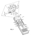
- FIG. 1 A shipping application in which a package is subject to a delivery from one location to another is depicted in Fig. 1 .
- a shipping application terminal 10 might be used to read a bar code symbol 5 disposed on article 15 as well as determine at least one dimension (width and/or length and/or height) of article 15.
- article 15 is shown as being provided by a package for delivery. However, it will be understood that article 15 can be provided by any object to be subject to spatial measurement.
- the dimension (dimensioning) information and other measurement (e . g ., volume measurement information) respecting article 15 might be used e . g ., to determine a cost for shipping a package or for determining a proper arrangement of the package in a shipping container.
- terminal 10 is configured to project a pair of dimensioning formations 20, 22 on a substrate such as an article 15 within a field of view 25 of terminal 10.
- Formations 20, 22 are regarded as dimensioning formations since frames of image data including representations of the formations can be processed for determining dimension information respecting an article.
- Terminal 10 in the embodiment of Fig. 1 can be configured to determine a dimension (e.g ., width, length, or height (thickness)) of article 15 by execution of a process in which terminal 10 determines a pixel distance between representations of formations 20, 22.
- Terminal 10 as shown in Fig. 1 can project a pair of substantially parallel laser beams 19, 21 which project light formations 20, 22 on article 15.
- terminal 10 With light formations 20, 22 being projected on article 15, terminal 10 can be actuated to capture a frame of image data having representations of light formations 20, 22.
- D is the dimension ( e . g ., width) of the package to be determined
- d n is the estimated present actual distance between the formations 20, 22 on the article
- P n is the pixel distance between representations of the edges of the package in the present captured frame of image data
- p n is the pixel distance between the representations of formations 20, 22 in the present captured frame of image data.
- a suitable edge detection algorithm can be employed. For example, a Laplacian or Laplacian of Gaussian (LoG) filter can be applied to the captured frame of image data for detection of edges.
- LiG Laplacian or Laplacian of Gaussian
- the distance d n (the estimated present actual distance between formations) can be a predetermined value based on design specifications for terminal 10. For example, if the beams forming light formations originate from sources that are 2 inches apart and are designed to be parallel to one another, it can be assumed that the formations will be formed at a 2 inch spacing at the package at every possible terminal to target distance. However, estimating the actual distance between formations 20, 22 based on design specifications of terminal 10 can lead to unacceptable inaccuracies in dimensioning and other spatial measurements of terminal 10 where terminal 10 deviates from the design specification significantly due to the tolerance introduced in the manufacturing process.
- terminal 10 can be provisioned so that the distance d n , the estimated present distance between light formations 20, 22, is determined utilizing recorded setup data recorded in a setup mode of operation.
- a setup mode according to the present description, manufacturing costs typically associated with features and steps for achieving precise alignment of one or more light sources can be avoided and yet highly precise dimensioning and other spatial measurements can be yielded.
- a setup mode is described with reference to Fig. 2 .
- terminal 10 can be moved between one or more reading distances to a target.
- terminal 10 is shown as being mounted on a sliding fixture 202 and is slidably moveable between various distances with respect to a target substrate 206 which in the example of Fig. 2 is shown as being provided by a test room wall.
- various setup data can be recorded.
- terminal 10 can be moved between two terminals to target distances in a setup mode; namely, between 1 foot from a target at position 210 and 6 feet from a target at position 212.
- pixel positions at which formations 20, 22 are represented ( e .
- a pixel distance value can be calculated based on the position information.
- the recording of pixel positions can be carried out automatically, e . g ., by subjecting a frame of image data having the formations represented therein to image processing or the determining of pixel positions can be carried out manually.
- an operator setting up terminal 10 can load a captured frame of image data having representations of formations 20, 22 therein into a picture viewing program having a pixel position readout functionality and the positions can be recorded by observation.
- the terminal 10 may project formations at the position of formations 20a, 22a as shown in Fig. 2 .
- an operator in a setup mode can maintain terminal 10 at a fixed position and can raise a target at different known distances from terminal 10.
- terminal 10 can be in a disassembled state.
- a setup mode can be carried out by moving imaging module 300 between various terminal to target distances prior to its incorporation into terminal housing 11.
- Housing 11 can be configured to be hand held so that terminal 10 when comprising housing 11 is a hand held terminal.
- Indicia reading terminal 10 can be conveniently implemented with use of a single housing such as housing 11 which houses the entirety of electronic circuitry necessary for carrying out the processing described herein. However, it will be understood that terminal 10 can be implemented utilizing electrical circuitry for carrying out the processing described herein that is spread between a plurality of spaced apart locations. For example, a subset of the described processing can be carried out by electrical circuitry with a hand held housing, and a subset of the processing can be carried out by electronic circuitry within a stationary housing. In one example, the various electronic circuitry components can be in communication over an IP network.
- setup data formation distances at various terminal to target distances d there can also be recorded as setup data formation distances at various terminal to target distances d; i . e ., the actual distance between the formations on a test substrate, e . g ., substrate 206.
- the actual setup data distances d 1 , d 2 can be recorded manually, e . g ., by measuring with a ruler; or automatically, e . g ., by disposing on target substrate 206 a grid having reference distance indicators and processing a frame of image data including a representation of the formations 20, 22, formations 20a, 22a and the grid. It is seen that both the present terminal to target distance, z n , and formation distance d n (the actual distance between formations 20, 22) can be determined utilizing a present pixel distance p n of formation representations and recorded setup data values ( e . g ., z 1 , z 2 , p 1 , p 2 , d 1 , d 2 ) and/or data (e.g., formula constants) determined utilizing such setup data recorded in a setup mode.
- setup data values e. g ., z 1 , z 2 , p 1 , p 2 , d 1
- terminal 10 can determine accurate spatial measurements, e . g ., terminal target distance measurements, and dimension (h, w, 1) measurements even where, as a result of manufacturing tolerances, at least one light formation is projected by the terminal angle that deviates from a desired angle of projection.
- a light formation projecting light beam is designed to project a beam in parallel with an imaging axis 30
- the light beam due to manufacturing tolerances might be projected substantially in parallel with the imaging axis but might deviate from a parallel relationship with the imaging axis by a deviation angle with less than 3 degrees.
- terminal 10 when operating in a spatial measurement mode can normalize changes in pixel distances measurements resulting from such deviation angles so that determined spatial measurements are substantially independent of the terminal to target distance.
- indicia reading terminal 10 can normalize terminal to target distance dependent changes in pixel distance measurements resulting from a deviation angle as described herein so that spatial measurements are substantially independent of the terminal to target distance.
- terminal 10 can be configured so that in an "in use" spatial measurement mode, the terminal can utilize the setup data recorded in a setup mode and/or data (e . g ., formula constants) determined utilizing the setup data to perform spatial measurement calculations.
- terminal 10 can apply various formulas e.g., Equation 2 or Equation 3 described herein having constants determined utilizing the setup data.
- the setup data recorded in a setup mode can include recorded pixel position data and, therefore, pixel distance data derivable from pixel position data at one or more controlled terminal to target distances.
- Recorded setup data recorded in a setup mode can also include actual formation distances (the actual recorded distance between formations) at various controlled terminal to target distances.
- Data determined utilizing recorded setup data recorded in a setup mode can include constants of formulas derived from the recorded setup data z distance, pixel distance, and/or actual formation distance data recorded in a setup mode.
- terminal 10 can include a preassembled imaging module configured to project formations.
- An example of an imaging module that can be utilized with terminal 10 is shown and described with reference to Figs. 3 and 4 .
- imaging module 300 for supporting various components of terminal 10 is described.
- Mounted on first circuit board 302 can be image sensor 32, illumination light sources 308 (e . g ., LEDs), and aiming light sources 310, 311 which can be provided by laser diode assemblies.
- a shroud 312 can be disposed forwardly of image sensor 32, and disposed forwardly of shroud 312 can be a lens holder 304, for holding an imaging lens.
- An optical plate 318 having a diffusion surface formed thereon for diffusing light from illumination light sources 308 can be disposed over holder 304 so that hole 322 fits over holder 304.
- An imaging module in an assembled form is shown in Fig. 4 . Imaging module 300 can be incorporated in and can be supported by hand held housing 11 of terminal 10.
- Terminal 10 can include image sensor 32 which can be provided on an integrated circuit having an image sensor pixel array 33 (image sensor array), column circuitry 34, row circuitry 35, a gain block 36, an analog-to-digital converter 37, and a timing and control circuit 38.
- Image sensor array 33 can be a two dimensional image sensor array having a plurality of light sensitive pixels formed in a plurality of rows and columns.
- Terminal 10 can further include a processor 60, an illumination control circuit 62, a lens control circuit 64, an imaging lens assembly 40, a direct memory access (DMA) unit 70, a volatile system memory 80 ( e .
- DMA direct memory access
- terminal 10 can include imaging axis 30.
- the recorded data including the derived formula constants described herein for determining a z distance and/or an actual formation distance (distance between formations) described with reference to a setup mode can be retained in nonvolatile memory 82, where the data can be accessed by processor 60 when executing steps of a program wherein a dimensioning value can be determined.
- terminal 10 can include a single image sensor array 33 disposed on a single image sensor 32, and terminal 10 can determine terminal to target distances (z distance) and horizontal/vertical dimensions (w, 1 dimensions) by processing image data corresponding to image signals generated by single image sensor array 33.
- illumination control circuit 62 can receive illumination control signals from processor 60 and can responsively deliver power to one or more illumination light sources such as light sources 308, and one or more aiming light sources such as aiming light sources 310 and 311 shown as being provided by laser diode assemblies.
- Terminal 10 can also include a keyboard 94, a trigger button 95, and a pointer controller 96 for input of data and for initiation of various controls and a display 97 for output of information to an operator user.
- Terminal 10 can also have an acoustic output device 99.
- Terminal 10 can also include a system bus 98 providing communication between processor 60 and various components of terminal 10.
- DMA unit 70 can be provided by, e .
- DMA unit 70 and processor 60 can be provided on a common integrated circuit.
- timing and control circuit 38 can send image sensor array 33 timing signals to array 33 such as reset, exposure control, and readout timing signals. After an exposure period, a frame of image data can be read out.
- Analog image signals that are read out of array 33 can be amplified by gain block 36 converted into digital form by analog-to-digital converter 37 and sent to DMA unit 70.
- DMA unit 70 in turn, can transfer digitized image data into volatile memory 80.
- Processor 60 can address one or more frames of image data retained in volatile memory 80 for processing of the frames for determining a dimension of an article and/or for decoding of decodable indicia represented therein.
- terminal 10 Further aspects of terminal 10 are now described with reference to Fig. 1 and the flow diagram of Fig. 6 .
- terminal 10 can incorporate a graphical user interface and can present buttons 106, 108, 110 corresponding to various operating modes such as a setup mode, a spatial measurement mode, and an indicia decode mode.
- the setup mode described herein can be performed as part of a manufacturing process prior to terminal 10 being delivered to an end user, the mode can also be made available as a selectable menu option that may be selected by a user who has access to a controlled test environment wherein terminal 10 to target distances can be controlled. It may be desirable to run the setup mode a second time after a first time on manufacture, e . g ., if aiming light sources of terminal 10 have become misaligned through use.
- terminal 10 can be configured so that selection of button 106 activates a setup mode, selection of button 108 activates a spatial measurement operating mode, and selection of decode button 110 activates a decode button.
- An exemplary setup mode has been described herein above with reference to Fig. 2 . While configuring terminal 10 to include a menu interface for use in selecting the mentioned modes of operation, it is understood that terminal 10 can be configured so that the various modes may be made active without use of a menu interface. Also, terminal 10 can be configured so that more than one of the described modes can be active simultaneously. For example, terminal 10 can be configured to perform spatial measurements simultaneously while decoding decodable indicia, and to output spatial measurement information simultaneously while outputting decoded message data.
- terminal 10 can perform one or more spatial measurements, e . g ., measurements to determine one or more of a terminal to target distance (z distance) or a dimension ( e . g ., w, 1, h) of an article or another spatial related measurement (e . g ., a volume measurement, a distance measurement between any two points).
- a spatial measurement operating mode terminal 10 can perform one or more spatial measurements, e . g ., measurements to determine one or more of a terminal to target distance (z distance) or a dimension ( e . g ., w, 1, h) of an article or another spatial related measurement (e . g ., a volume measurement, a distance measurement between any two points).
- terminal 10 can capture a frame of image data. Terminal 10 can be configured so that block 602 is executed responsively to trigger 95 being initiated.
- terminal 10 can find representations of formations 20, 22 in the captured frame of image data captured at block 602. Representations of formations 20, 22 will typically include a cluster (a set of positionally adjacent pixel values) of high white level pixel values and accordingly, can be easily discriminated from other pixel values. At block 606, terminal 10 can determine the pixel positions associated with each light pattern formation 20, 22; and therefrom, can determine a pixel distance value, p n , for the set of formations. A center of a representation of a formation 20, 22 can be regarded as a pixel position for the formation representation.
- terminal 10 can determine an actual distance, d n , between formations 20, 22 that have been projected on a substrate, e.g., article 15 within a field of view 25 of terminal 10.
- terminal 10 can utilize recorded data recorded in a setup mode of operation. For example, in a setup mode there can be recorded the constants (coefficients) of Equations 2 or 3, and terminal 10 at block 610 can apply Equation 2 at block 610 for determination of a present terminal to target distance (z distance) and can apply Equation 3 at block 610 for determination of a present distance, d n , between formations 20, 22.
- terminal 10 can determine the present formation distance d n , by reading a predetermined value based on the design specifications of terminal 10.
- terminal 10 at block 614 can determine pixel positions of the frame of image data captured at block 602 corresponding to edges 130, 132 of article 15 being subject to dimension measuring (dimensioning).
- terminal 10 can apply a suitable edge detection mask (e . g ., a 3x3 kernel mask) to the captured frame of image data.
- Suitable edge detection masks can include, e . g ., Laplacian or Laplacian of Gaussian (LoG) masks.
- a line can be drawn in the frame of image data between the representations of formations 20, 22 and the points of the edge positions intersecting the line can be selected as the edge representation points of interest for determining the edge pixel distance, P n .
- terminal 10 can also determine a pixel distance, P n ', between representations of vertical edges 134, 136 of article 15 using any of the methods described herein for determining the pixel distance of representations of edges 130, 132.
- terminal 10 further at block 614 can apply the edge pixel distance and the formation pixel distance, p n together with the determined actual formation distance, d n , in the formula of Equation 1 to return a package dimension ( e . g ., the X direction width dimension (w) of article 15).
- Terminal 10 at block 614 can also determine a present z distance (terminal to target object distance) utilizing recorded data recorded during a setup mode, e . g ., by application of the formula of Equation 2, constants of which can be stored in a memory, e . g ., memory accessible by processor during the setup mode or determined at block 614.
- terminal 10 can also determine a length of a dimension, 1, of article 15 applying Equation 1, substituting P n ' for P n therein, where P n ' is the pixel distance between article representation edges in the Y direction (see the X, Y, Z reference axes in Fig. 1 ).
- terminal 10 can output the determined package dimension value, e . g ., width, w, length, 1, height, h, present z distance value ( i . e ., the distance between terminal 10 and the object 15 being subject to measurement), and present actual formation distance, d n , value.
- terminal 10 can display the data on display 97.
- terminal 10 can be configured so that when a spatial measurement mode is made active, terminal 10 waits for trigger 95 to be actuated (depressed and released) a first and second time, processes a frame of image data captured responsively to each trigger actuation and automatically outputs a volume dimension of article 15 after processing a frame captured responsively to the second trigger actuation. More specifically in the described embodiment, terminal 10 after trigger 95 is depressed a first time can capture and process a first frame of image data to determine width and length (w and 1) dimensions of an article 15 as has been described herein.
- terminal 10 and/or article 15 can be moved in such manner that when a trigger 95 is pulled a second time, terminal 10 will have a field of view 25 in which an adjacent side of article 15 is encompassed within a field of view 25 of terminal 10 in such a manner that formations are projected at the location of formations 20', 22' as is shown in Fig. 1 .
- terminal 10 when trigger 95 is depressed a second time after a spatial measurement mode is made active terminal 10 can capture and processes a frame of image data to determine a height dimension, h, utilizing Equation 1 with new edge pixel distance values substituted for p n in Equation 1, and utilizes the determined width (w), length (l), and height (h) dimensions to return a volume measurement for terminal 10.
- terminal 10 after a spatial measurement mode is made active, waits for trigger 95 to be actuated first and second times. After actuation ( e . g ., depression and release) of trigger 95 a first time, terminal 10 can capture and process a frame of image data to calculate one or two of w, l, h dimensions of an article in the field of view.
- terminal 10 can capture and process a second frame of image data to calculate at least two of w, l, h dimensions of article x and multiply the dimension(s) calculated with the dimension(s) calculated utilizing the first frame of information to return a volume value which can be output ( e . g ., to a display 97).
- terminal 10 for example at block 618 when executing the steps of the flow diagram of Fig. 6 can automatically return a missing dimension value e . g ., a height value, h, by processing a frame of image data to determine one or more article dimensions, e . g ., a width or length or height of article 15 utilizing previously known characteristics of the types of articles that are expected to be subjected to image capture by terminals.
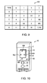
- terminal 10 can be configured so that at block 618 terminal 10 queries a database, e . g ., a lookup table such as lookup table 900 of Fig. 9 correlating box dimensions (w, l, h) of various candidate box types.
- a lookup table in communication with terminal 10 which can be co-located at terminal 10 can be provided with rows corresponding to each candidate box size correlating box dimensions and a volume value. If no two candidate box sizes share a common dimension, it will be seen that with use of a lookup table as described, a volume measurement for an article in the form of a box can be returned utilizing the lookup table by determining a single dimension, (w, l, h) of such a box.
- a single dimension, (w, l, h) of such a box In the lookup table 900 as shown in Fig.
- FIG. 9 there is shown a lookup table configured for use in an application wherein there are five candidate boxes with none of the boxes having a dimension (w, l, h) in common with another candidate box.
- terminal 10 utilizing lookup table 900 can determine any box dimension and a volume value for a box by determining by way of image processing a single dimension (w, l, or h) for a box and utilizing lookup table 900 to determine the remaining dimensions and volume value for the box.
- box sizes (types) can be discriminated and missing box dimension and volume values determined utilizing only two determined dimension values ( e . g ., w and l) determined by way of image processing.
- a volume value of an article 15, as well as a type identifier of article 15 can be output to display 97 at block 618.
- terminal 10 at block 614 can find edges 130, 132 by utilizing an appropriate edge finding image processing algorithm.
- terminal 10 at block 614 can find edges of an article utilizing feature information designated by an operator. For example, by reading edge positions of a captured image that are designated by an operator.
- terminal 10 can be configured so when a trigger 95 is depressed to capture a frame with a spatial measurement mode made active, terminal 10 outputs the frame to display 97 for spatial viewing by an operator together with operator controllable indicators superimposed on the displayed image.
- Terminal 10 can be configured so that an operator can control the positioning of the superimposed indicators e.g., cursors with use of pointer controller 96 to designate edge positions of a captured frame captured for processing for determining of dimensioning and/or other measurement information.
- terminal 10 can be configured so that in a spatial measurement mode terminal 10 displays on display 97 captured frames captured for processing for determination of measurement information.
- Terminal 10 can be configured so that together with representation 115 of article 15 there can be display indicators on display 97 for use in designating edge positions.
- the formations are in the form of cursors 902, 904, 906, 908, including a first set of cursors 902 and 904, and a second set of cursors 906 and 908.
- Terminal 10 can be configured so that an operator with use of pointer controller 96 and pointer 196 can move first set of cursors 902, 904 for designating edges of an article in the width dimension of the article 15 and can utilize cursors 906, 908 to designate edges of article 15 in a length dimension of article 15.
- Terminal 10 can also be configured so that an operator can apply the cursors 902, 904, 906, 908 on the representations of the four corners of an article, represented in the form of a box, and terminal 10 can draw lines through such designated points to define w and 1 dimension edges of the representations of article 15 being processed.
- An embodiment where terminal 10 is configured so that an operator can designate edge positions on an article representation either by designating edges representations directly or article corner representations relative to an article representation, terminal 10 at block 614 in finding edge positions of an article representation can read the designated positions designated by an operator.
- terminal 10 can be configured so that terminal 10 can adjust a position of designed corner representation designated manually by an operator responsively to image processing of the frame of image data including the article representation.
- terminal 10 can be configured so that responsively to a corner representation being designated, terminal 10 establishes a subset of the image data making up of the frame of image data as a region of interest and then subjects the image data of the region of interest to image processing, e.g., application of edge detection masks for location edge representations within the region of interest.
- Terminal 10 can be configured to adjust the position of the corner position if the processing of the image data indicates that the actual position of the corner representation is different than the position of the corner representation designated by the operation.
- the region of interest can be positionally related to the designated corner representation designated by the operator.
- the region of interest can be a predetermined two dimensional set of pixel positions surrounding the center pixel position of a corner representation designated by an operator.
- terminal 10 automatically adjusts a designated corner position by subjecting a region of interest about the designated corner point to edge finding image processing, it is seen that terminal 10 utilizes both user (operator) designated feature information designated by an operator and edge detection image processing in finding edges of an article representation.
- terminal 10 finds edge representations of an article representation responsively to an operator designating a limited number of corner representations of the article representation. For example, terminal 10 can prompt an operator to designate a single corner representation of a frame of image data which position may or may not be single corner representation of a frame of image data which position may or may not be then adjusted responsively to image processing as described above. Terminal 10 can then determine the edge positions of the article representation by application of an edge detection image processing algorithm and can utilize the user designated corner position in verifying that the detected edges are actual article edge representations and not "false" edge position representation as might be created, e . g ., by a representation of an article including a representation of a photograph of a box.
- terminal 10 can automatically determine the locations of representations of article edges in a captured frame of image data by drawing lines through a limited number of corner positions designated by an operator (which may be adjusted or not adjusted as described) and interpolating missing lines as is necessary.
- terminal 10 responsively to an operator designating successive first, second, and third corner representations have been designated, can draw a first imaginary line intersecting the first and second designated corner representations and a second imaginary line intersecting the second and third designated corner representation. Terminal 10 can then draw an imaginary third line parallel to the first line and intersecting the third designated corner, and an imaginary fourth line parallel to the second line and intersecting the first designated corner.
- Edge pixel distances can be determined utilizing the first and third lines and/or the second and fourth lines.
- terminal 10 can be configured so that with a decode mode active, depressing trigger 95 drives terminal 10 into an active reading state.
- terminal 10 can attempt to decode decodable indicia such as bar code symbols or OCR characters represented in captured frames of image data.
- terminal 10 can be adapted so that processor 60 can subject to a decode attempt a frame of image data retained in memory 80. For example, in attempting to decode a 1D bar code symbol represented in a frame of image data, processor 60 can execute the following processes. First, processor 60 can launch a scan line in a frame of image data, e .
- processor 60 can perform a second derivative edge detection to detect edges. After completing edge detection, processor 60 can determine data indicating widths between edges. Processor 60 can then search for start/stop character element sequences, and if found, derive element sequence characters character by character by comparing with a character set table. For certain symbologies, processor 60 can also perform a checksum computation. If processor 60 successfully determines all characters between a start/stop character sequence and successfully calculates a checksum (if applicable), processor 60 can output a decoded message.
- processor 60 can one or more of (a) initiate transfer of the decoded message to an external device, (b) initiate display of a decoded message on a display of terminal 10, (c) attach a flag to a buffered decoded message determined by processor 60, and (d) write the decoded message to an address of long term memory, e . g ., 82 and/or 84.
- processor 60 can send a signal to an acoustic output device 99 of terminal 10 to emit a beep.
- terminal 10 can one or more (a) initiate transfer of the measurement information to an external device, (b) initiate display of the measurement information to a display of terminal 10, (c) attach a flag to buffered measurement information and (d) write the measurement information to an address of a long term memory, e.g., 82 or 84.
- a long term memory e.g., 82 or 84.
- terminal 10 is configured to project a pair of formations 20, 22 on substrate 15 for use in determining a dimension of a substrate, provided in the example by article 15.
- Such formations can be produced with use of a light generating assembly having a pair of laser diode assemblies 310, 311 as shown in Figs. 3 and 4 and further as is shown in the top view of Fig. 7 .
- a light generating assembly can be employed that includes, e.g., a single laser diode assembly in combination with light shaping elements adapted so that a pair of light formations 20, 22 are projected on a substrate.
- each laser diode assembly can be replaced by a light emitting diode (LED) in combination with light shaping optics suitable for projecting of a light formation.
- terminal 10 can be adapted to project a single light formation 20 on substrate 206 provided by article 15 for purposes of determining one or more dimensions of terminal 10.
- Fig. 8 there is shown a top view of an alternative imaging module 300' having a single laser diode assembly 310 for projecting a single light formation 20 on substrate 15.
- Module 300' is identical to module 300 except that second laser diode assembly 311 is deleted.
- terminal 10 includes an imaging module 300' that projects a single light formation 20 rather than a plurality of light formations
- the recording of data in a setup mode is the same as in the example described above except that a center or other fixed reference pixel position value is substituted for the second formation pixel position data recording.
- the pixel position of a representation of single formation 20 relative to an arbitrary reference pixel position will vary as the z distance of terminal 10 is changed.
- steps including determination of an actual distance between a pair of projected formations 20, 22 can be substituted by steps for determining the actual distance between a position of a single formation 20 and a reference position e . g ., center of a field of view of terminal 10.
- a terminal including a single formation projecting light generating assembly where the assembly projects a light beam forming the formation substantially parallel to an imaging axis 30, the single light formation is projected at a position spaced apart from the position at which an imaging axis 30 of terminal 10 intersects a substrate onto which the formation is projected.
- the pixel position of a representation of the formation will vary in a captured frame of image data in a manner that depends on the spacing between terminal 10 and the substrate.
- projected dimensioning formations 20, 22 can be projected using visible light rays. Accordingly, the projecting of a pair of formations on a substrate, e.g., substrate 15 allows terminal 10 to be easily oriented in an orientation relative to article 15 that will yield a desired distance measurement.
- terminal 10 For purposes of improving the accuracy with which a dimension or an article can be measured, terminal 10, where equipped with a light generating assembly projecting a pair of light formations, should be aligned with an article in such manner that the pair of formations are projected in a substantially parallel orientation relative to a first ( e . g ., edge 134) edge of the article being subject to dimensioning and substantially perpendicularly relative to a second edge ( e . g ., edge 132) of the article being subjected to dimensioning where the article being subject to dimensioning is a typical box comprising a plurality of substantially straight, right angle related edges.
- a spatial measurement mode can be selected (activated), terminal 10 can be manually aligned so that formations 20, 22 are projected as shown in Fig. 1 substantially parallel to a first edge of an article and substantially perpendicular to a second edge of an article, an actuator e . g ., trigger 95 can be actuated to capture a frame of image data representing the article, and the frame of image data can be processed to determine a dimension e . g ., w, l, h of the article, in a manner described herein.
- terminal 10 by processing the frame of image data can determine P n , the distance between representations of a pair of opposing edges ( e .
- an instruction manual can be provided.
- the instruction manual can be e . g ., a paper instruction manual and an electronically displayed instruction manual for display e . g ., on display 97 or a played audio recording instruction manual.
- the instruction manual can include the instruction that an operator should align terminal 10 so that formations 20, 22 are oriented so as to be oriented at least one of parallel with a first edge of an article or perpendicular to a second edge of article 15 prior to a time that trigger 95 is actuated to capture a frame of image data to be subject to processing for measurement determination.
Abstract
Description
- The present invention relates to imaging apparatuses generally and in particular, to an imaging apparatus having spatial measurement functionality.
- In the field of transportation and shipping of goods, it can be useful to perform spatial measurements with respect to packages or other objects remotely, e.g., goods that are stacked on a pallet or in the interior of a truck or shipping container. Conventional approaches for determining an object distance include approaches using a distant remote sensor or stereo vision to estimate an object distance.
- The features described herein can be better understood with reference to the drawings described below. The drawings are not necessarily to scale, emphasis instead generally being placed upon illustrating the principles of the invention. In the drawings, like numerals are used to indicate like parts throughout the various views.
-
Fig. 1 is a system view showing an indicia reading terminal being used to determine a dimension of an article in a field of view of the indicia reading terminal. -
Fig. 2 is a view illustrating an exemplary embodiment of an indicia reading terminal operating in a setup mode, wherein various setup data can be recorded at various terminal to target distances. -
Fig. 3 is a perspective exploded view of an imaging module which can be incorporated in a hand held housing of an indicia reading terminal. -
Fig. 4 . is a perspective assembly view of an imaging module as shown inFig. 3 . -
Fig. 5 is a block diagram illustrating various hardware components of an indicia reading terminal in one embodiment. -
Fig. 6 is a flow diagram illustrating operation of an indicia reading terminal in a measurement mode of operation in one embodiment. -
Fig. 7 is a top view of an imaging module projecting a pair of dimensioning light formations for use in determining dimensioning information shown in combination with an article being subject to dimensioning. -
Fig. 8 is a top view of an imaging module projecting a single dimensioning light formation for use in determining dimensioning information shown in combination with an article being subject to dimensioning. -
Fig. 9 is a diagram illustrating an exemplary database in the form of a lookup table which may be utilized by an indicia reading terminal. -
Fig. 10 is a view of an indicia reading terminal having a user interface configured to enable an operator to designate edge information of a frame of image data subject to image processing. - There is described herein an indicia reading terminal which, in one embodiment, is operable in a setup mode in which various data is recorded as the terminal is positioned at a known distance from a target. In an "in use" mode of operation made active after the setup mode is complete, the terminal can utilize the recorded data determined in the setup mode to provide highly accurate dimension (dimensioning) measurements and other distance measurements. There is shown in
Fig. 1 an indicia reading terminal according to an embodiment described herein. An indicia reading terminal can have a setup mode and one or more "in use" operating modes. The "in use" operating modes can include a spatial measurement mode in which the terminal determines spatial measurement information, e.g., a terminal to object distance, z, one or more dimensions (e.g., width, length, and/or height) of an object, such as a package, and an indicia reading mode in which the terminal decodes a message encoded in a decodable indicia. In an indicia reading mode the terminal can decode a bar code symbol to determine a decoded message corresponding to a bar code symbol. - A shipping application in which a package is subject to a delivery from one location to another is depicted in
Fig. 1 . In ashipping application terminal 10 might be used to read abar code symbol 5 disposed onarticle 15 as well as determine at least one dimension (width and/or length and/or height) ofarticle 15. In the specific embodiment described,article 15 is shown as being provided by a package for delivery. However, it will be understood thatarticle 15 can be provided by any object to be subject to spatial measurement. The dimension (dimensioning) information and other measurement (e.g., volume measurement information) respectingarticle 15 might be used e.g., to determine a cost for shipping a package or for determining a proper arrangement of the package in a shipping container. In the specific example ofFig. 1 ,terminal 10 is configured to project a pair ofdimensioning formations article 15 within a field ofview 25 ofterminal 10.Formations -
Terminal 10 in the embodiment ofFig. 1 can be configured to determine a dimension (e.g., width, length, or height (thickness)) ofarticle 15 by execution of a process in whichterminal 10 determines a pixel distance between representations offormations Terminal 10 as shown inFig. 1 can project a pair of substantiallyparallel laser beams 19, 21 whichproject light formations article 15. Withlight formations article 15,terminal 10 can be actuated to capture a frame of image data having representations oflight formations light formations article 15 respecting a surface can be determined by the formula:
- where D is the dimension (e.g., width) of the package to be determined, dn is the estimated present actual distance between the
formations formations - In one method, the distance dn (the estimated present actual distance between formations) can be a predetermined value based on design specifications for
terminal 10. For example, if the beams forming light formations originate from sources that are 2 inches apart and are designed to be parallel to one another, it can be assumed that the formations will be formed at a 2 inch spacing at the package at every possible terminal to target distance. However, estimating the actual distance betweenformations terminal 10 can lead to unacceptable inaccuracies in dimensioning and other spatial measurements ofterminal 10 whereterminal 10 deviates from the design specification significantly due to the tolerance introduced in the manufacturing process. - In one embodiment,
terminal 10 can be provisioned so that the distance dn, the estimated present distance betweenlight formations - An exemplary setup mode is described with reference to
Fig. 2 . In asetup mode terminal 10 can be moved between one or more reading distances to a target. In the example shown inFig. 2 ,terminal 10 is shown as being mounted on a slidingfixture 202 and is slidably moveable between various distances with respect to atarget substrate 206 which in the example ofFig. 2 is shown as being provided by a test room wall. At each known distance, various setup data can be recorded. In one example,terminal 10 can be moved between two terminals to target distances in a setup mode; namely, between 1 foot from a target atposition position 212. At each controlled distance, pixel positions at whichformations terminal 10 can load a captured frame of image data having representations offormations terminal 10 is designed to projectbeams 19, 21 in parallel,terminal 10, according to manufacturing tolerances mayproject beams 19, 21 in such manner thatbeams 19, 21 are not parallel. Accordingly, the position offormations terminal 10 is moved. At a first distance (e.g., 1 foot)terminal 10 mayproject formations formations Fig. 2 . At a second distance (e.g., 6 feet) theterminal 10 may project formations at the position offormations Fig. 2 . Rather than utilizing a slidingfixture 202 in a setup mode to achieve various controlled terminal to target distances, an operator in a setup mode can maintainterminal 10 at a fixed position and can raise a target at different known distances fromterminal 10. In a setup mode,terminal 10 can be in a disassembled state. For example, a setup mode can be carried out by movingimaging module 300 between various terminal to target distances prior to its incorporation intoterminal housing 11.Housing 11 can be configured to be hand held so thatterminal 10 when comprisinghousing 11 is a hand held terminal. -
Indicia reading terminal 10 can be conveniently implemented with use of a single housing such ashousing 11 which houses the entirety of electronic circuitry necessary for carrying out the processing described herein. However, it will be understood thatterminal 10 can be implemented utilizing electrical circuitry for carrying out the processing described herein that is spread between a plurality of spaced apart locations. For example, a subset of the described processing can be carried out by electrical circuitry with a hand held housing, and a subset of the processing can be carried out by electronic circuitry within a stationary housing. In one example, the various electronic circuitry components can be in communication over an IP network. - Once a set of pixel positions and therefore pixel distances are recorded as setup data at a pair of terminal to target distances, a present terminal to target (z) distance can be determined from any measured pixel distance, pn, (where pn can be measured by subjecting a frame of image data to image processing) using the formula:

- where a and b are constants solved applying linear interpolation using the set of linear interpolation formulas p1=a+b/z1; p2=a+b/z2, where z1 is a first recorded setup mode terminal to target distance recorded as a setup data value, z2 is the second recorded setup mode terminal to target distance recorded as a setup data value, p1 is the recorded pixel distance at the terminal to target distance z1 recorded as a setup data value, and p2 is the pixel distance at the terminal to target distance z2 recorded as a setup data value.
- At each setup mode terminal to target distance, there can also be recorded as setup data formation distances at various terminal to target distances d; i.e., the actual distance between the formations on a test substrate, e.g.,
substrate 206. Once formation distances, d1 and d2 are recorded as setup data at a set of controlled terminal to target distances, z1 and z2, where pixel distances p1 and p2 are also recorded at the setup mode terminal to target distances z1, z2, the distance dn, the present distance betweenformations 
- where zn is the present terminal to target distance which can be determined utilizing the measured present pixel distance, pn, by applying
Equation 2, where f and g are constants solved applying linear interpolation utilizing the set of linear interpolation formulas z1=f+g/d1; z2=f+g/d2; where z1 is a first setup mode terminal to target distance recorded as a setup data value, z2 is the second terminal to target distance recorded as a setup data value, and d1 and d2 are the actual recorded setup data value distances (the distance betweenformations 20, 22) while the terminal is positioned at the first distance, z1, and the second distance, z2, respectively. The actual setup data distances d1, d2 can be recorded manually, e.g., by measuring with a ruler; or automatically, e.g., by disposing on target substrate 206 a grid having reference distance indicators and processing a frame of image data including a representation of theformations formations formations 20, 22) can be determined utilizing a present pixel distance pn of formation representations and recorded setup data values (e.g., z1, z2, p1, p2, d1, d2) and/or data (e.g., formula constants) determined utilizing such setup data recorded in a setup mode. - By recording setup data in the manner described herein, terminal 10 can determine accurate spatial measurements, e.g., terminal target distance measurements, and dimension (h, w, 1) measurements even where, as a result of manufacturing tolerances, at least one light formation is projected by the terminal angle that deviates from a desired angle of projection. For example, where a light formation projecting light beam is designed to project a beam in parallel with an
imaging axis 30, the light beam, due to manufacturing tolerances might be projected substantially in parallel with the imaging axis but might deviate from a parallel relationship with the imaging axis by a deviation angle with less than 3 degrees. Similarly where terminal 10 is designed to project a first and second light formation, the terminal might be designed to project beams forming the formations parallel to one another, but due to manufacturing tolerances, the beams might, though substantially parallel, diverge at a deviation angle of less than 5%. It will be seen that utilizing setup data as described herein, terminal 10 when operating in a spatial measurement mode can normalize changes in pixel distances measurements resulting from such deviation angles so that determined spatial measurements are substantially independent of the terminal to target distance. Utilizing setup data as described herein, it will be understood thatindicia reading terminal 10 can normalize terminal to target distance dependent changes in pixel distance measurements resulting from a deviation angle as described herein so that spatial measurements are substantially independent of the terminal to target distance. - With setup data recorded in a setup mode, terminal 10 can be configured so that in an "in use" spatial measurement mode, the terminal can utilize the setup data recorded in a setup mode and/or data (e.g., formula constants) determined utilizing the setup data to perform spatial measurement calculations. In utilizing the setup data recorded in a setup mode and/or data determined utilizing the setup data, terminal 10 can apply various formulas e.g.,
Equation 2 orEquation 3 described herein having constants determined utilizing the setup data. As described herein the setup data recorded in a setup mode can include recorded pixel position data and, therefore, pixel distance data derivable from pixel position data at one or more controlled terminal to target distances. Recorded setup data recorded in a setup mode can also include actual formation distances (the actual recorded distance between formations) at various controlled terminal to target distances. Data determined utilizing recorded setup data recorded in a setup mode can include constants of formulas derived from the recorded setup data z distance, pixel distance, and/or actual formation distance data recorded in a setup mode. - Referring again to terminal 10 as shown in
Fig. 1 , terminal 10 can include a preassembled imaging module configured to project formations. An example of an imaging module that can be utilized withterminal 10 is shown and described with reference toFigs. 3 and 4 . - Referring to
Figs. 3 and 4 ,imaging module 300 for supporting various components ofterminal 10 is described. Mounted onfirst circuit board 302 can beimage sensor 32, illumination light sources 308 (e.g., LEDs), and aiminglight sources shroud 312 can be disposed forwardly ofimage sensor 32, and disposed forwardly ofshroud 312 can be alens holder 304, for holding an imaging lens. Anoptical plate 318 having a diffusion surface formed thereon for diffusing light from illuminationlight sources 308 can be disposed overholder 304 so thathole 322 fits overholder 304. An imaging module in an assembled form is shown inFig. 4 .Imaging module 300 can be incorporated in and can be supported by hand heldhousing 11 ofterminal 10. - A block diagram of an electrical component circuit diagram supporting operations of
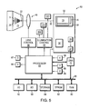
terminal 10 is shown inFig. 5 .Terminal 10 can includeimage sensor 32 which can be provided on an integrated circuit having an image sensor pixel array 33 (image sensor array),column circuitry 34,row circuitry 35, again block 36, an analog-to-digital converter 37, and a timing andcontrol circuit 38. Image sensor array 33 can be a two dimensional image sensor array having a plurality of light sensitive pixels formed in a plurality of rows and columns.Terminal 10 can further include aprocessor 60, anillumination control circuit 62, alens control circuit 64, animaging lens assembly 40, a direct memory access (DMA)unit 70, a volatile system memory 80 (e.g., a RAM), a nonvolatile system memory 82 (e.g., EPROM), astorage memory 84, a wireline input/output interface 90 (e.g., Ethernet), and an RF transceiver interface 92 (e.g., IEEE 802.11). As shown throughout various views, terminal 10 can includeimaging axis 30. In one example, the recorded data including the derived formula constants described herein for determining a z distance and/or an actual formation distance (distance between formations) described with reference to a setup mode can be retained innonvolatile memory 82, where the data can be accessed byprocessor 60 when executing steps of a program wherein a dimensioning value can be determined. In the embodiment ofFig. 5 , terminal 10 can include a single image sensor array 33 disposed on asingle image sensor 32, and terminal 10 can determine terminal to target distances (z distance) and horizontal/vertical dimensions (w, 1 dimensions) by processing image data corresponding to image signals generated by single image sensor array 33. - Regarding
illumination control circuit 62,illumination control circuit 62 can receive illumination control signals fromprocessor 60 and can responsively deliver power to one or more illumination light sources such aslight sources 308, and one or more aiming light sources such as aiminglight sources Terminal 10 can also include akeyboard 94, atrigger button 95, and apointer controller 96 for input of data and for initiation of various controls and adisplay 97 for output of information to an operator user.Terminal 10 can also have anacoustic output device 99.Terminal 10 can also include asystem bus 98 providing communication betweenprocessor 60 and various components ofterminal 10.DMA unit 70 can be provided by, e.g., a field programmable gate array (FPGA) or an application specific integrated circuit (ASIC). While shown as being separate units,DMA unit 70 andprocessor 60 can be provided on a common integrated circuit. In response to control signals received fromprocessor 60, timing andcontrol circuit 38 can send image sensor array 33 timing signals to array 33 such as reset, exposure control, and readout timing signals. After an exposure period, a frame of image data can be read out. Analog image signals that are read out of array 33 can be amplified bygain block 36 converted into digital form by analog-to-digital converter 37 and sent toDMA unit 70.DMA unit 70, in turn, can transfer digitized image data intovolatile memory 80.Processor 60 can address one or more frames of image data retained involatile memory 80 for processing of the frames for determining a dimension of an article and/or for decoding of decodable indicia represented therein. - Further aspects of
terminal 10 are now described with reference toFig. 1 and the flow diagram ofFig. 6 . - It is seen with reference to the view of
Fig. 1 thatterminal 10 can incorporate a graphical user interface and can presentbuttons terminal 10 being delivered to an end user, the mode can also be made available as a selectable menu option that may be selected by a user who has access to a controlled test environment wherein terminal 10 to target distances can be controlled. It may be desirable to run the setup mode a second time after a first time on manufacture,e.g., if aiming light sources ofterminal 10 have become misaligned through use. Further respecting the menu buttons, terminal 10 can be configured so that selection ofbutton 106 activates a setup mode, selection ofbutton 108 activates a spatial measurement operating mode, and selection ofdecode button 110 activates a decode button. An exemplary setup mode has been described herein above with reference toFig. 2 . While configuringterminal 10 to include a menu interface for use in selecting the mentioned modes of operation, it is understood that terminal 10 can be configured so that the various modes may be made active without use of a menu interface. Also, terminal 10 can be configured so that more than one of the described modes can be active simultaneously. For example, terminal 10 can be configured to perform spatial measurements simultaneously while decoding decodable indicia, and to output spatial measurement information simultaneously while outputting decoded message data. - Regarding a spatial measurement mode, an exemplary spatial measurement mode which may be made active by selection of
button 106 is described with reference to the flow diagram ofFig. 6 . In a spatial measurement operating mode, terminal 10 can perform one or more spatial measurements, e.g., measurements to determine one or more of a terminal to target distance (z distance) or a dimension (e.g., w, 1, h) of an article or another spatial related measurement (e.g., a volume measurement, a distance measurement between any two points). Returning to the illustrative example ofFig. 6 , atblock 602, terminal 10 can capture a frame of image data.Terminal 10 can be configured so thatblock 602 is executed responsively to trigger 95 being initiated. Atblock 606, terminal 10 can find representations offormations block 602. Representations offormations block 606, terminal 10 can determine the pixel positions associated with eachlight pattern formation formation block 610, terminal 10 can determine an actual distance, dn, betweenformations article 15 within a field ofview 25 ofterminal 10. In executingblock 610, terminal 10 can utilize recorded data recorded in a setup mode of operation. For example, in a setup mode there can be recorded the constants (coefficients) ofEquations block 610 can applyEquation 2 atblock 610 for determination of a present terminal to target distance (z distance) and can applyEquation 3 atblock 610 for determination of a present distance, dn, betweenformations block 610, terminal 10 can determine the present formation distance dn, by reading a predetermined value based on the design specifications ofterminal 10. - Further referring to the flow diagram of
Fig. 6 terminal 10 atblock 614 can determine pixel positions of the frame of image data captured atblock 602 corresponding toedges article 15 being subject to dimension measuring (dimensioning). For finding representations of edges, terminal 10 can apply a suitable edge detection mask (e.g., a 3x3 kernel mask) to the captured frame of image data. Suitable edge detection masks can include, e.g., Laplacian or Laplacian of Gaussian (LoG) masks. When the pixel positions representing a pair of opposingedges formations block 602 terminal 10 can also determine a pixel distance, Pn', between representations ofvertical edges article 15 using any of the methods described herein for determining the pixel distance of representations ofedges - When the edge pixel distance, Pn, is determined at
block 614, terminal 10 further atblock 614 can apply the edge pixel distance and the formation pixel distance, pn together with the determined actual formation distance, dn, in the formula ofEquation 1 to return a package dimension (e.g., the X direction width dimension (w) of article 15).Terminal 10 atblock 614 can also determine a present z distance (terminal to target object distance) utilizing recorded data recorded during a setup mode, e.g., by application of the formula ofEquation 2, constants of which can be stored in a memory, e.g., memory accessible by processor during the setup mode or determined atblock 614. Atblock 614, terminal 10 can also determine a length of a dimension, 1, ofarticle 15 applyingEquation 1, substituting Pn' for Pn therein, where Pn' is the pixel distance between article representation edges in the Y direction (see the X, Y, Z reference axes inFig. 1 ). Atblock 618, terminal 10 can output the determined package dimension value, e.g., width, w, length, 1, height, h, present z distance value (i.e., the distance betweenterminal 10 and theobject 15 being subject to measurement), and present actual formation distance, dn, value. When outputting such data, terminal 10 can display the data ondisplay 97. - In one embodiment of a spatial measurement mode, terminal 10 can be configured so that when a spatial measurement mode is made active, terminal 10 waits for
trigger 95 to be actuated (depressed and released) a first and second time, processes a frame of image data captured responsively to each trigger actuation and automatically outputs a volume dimension ofarticle 15 after processing a frame captured responsively to the second trigger actuation. More specifically in the described embodiment, terminal 10 aftertrigger 95 is depressed a first time can capture and process a first frame of image data to determine width and length (w and 1) dimensions of anarticle 15 as has been described herein. With w and 1 dimensions determined responsively to a first trigger depress and release, an operator can move terminal 10 and/orarticle 15 in such manner that when atrigger 95 is pulled a second time, terminal 10 will have a field ofview 25 in which an adjacent side ofarticle 15 is encompassed within a field ofview 25 ofterminal 10 in such a manner that formations are projected at the location of formations 20', 22' as is shown inFig. 1 . Accordingly, whentrigger 95 is depressed a second time after a spatial measurement mode is made active terminal 10 can capture and processes a frame of image data to determine a height dimension, h, utilizingEquation 1 with new edge pixel distance values substituted for pn inEquation 1, and utilizes the determined width (w), length (l), and height (h) dimensions to return a volume measurement forterminal 10. According to the described embodiment, terminal 10, after a spatial measurement mode is made active, waits fortrigger 95 to be actuated first and second times. After actuation (e.g., depression and release) of trigger 95 a first time, terminal 10 can capture and process a frame of image data to calculate one or two of w, l, h dimensions of an article in the field of view. After an actuation of trigger 95 a second time, terminal 10 can capture and process a second frame of image data to calculate at least two of w, l, h dimensions of article x and multiply the dimension(s) calculated with the dimension(s) calculated utilizing the first frame of information to return a volume value which can be output (e.g., to a display 97). - In another embodiment, terminal 10, for example at
block 618 when executing the steps of the flow diagram ofFig. 6 can automatically return a missing dimension value e.g., a height value, h, by processing a frame of image data to determine one or more article dimensions, e.g., a width or length or height ofarticle 15 utilizing previously known characteristics of the types of articles that are expected to be subjected to image capture by terminals. For example, terminal 10 can be configured so that atblock 618 terminal 10 queries a database, e.g., a lookup table such as lookup table 900 ofFig. 9 correlating box dimensions (w, l, h) of various candidate box types. In certain data collection applications it is expected that certain articles might be made available in a limited number of predetermined sizes. In such applications a lookup table in communication withterminal 10 which can be co-located atterminal 10 can be provided with rows corresponding to each candidate box size correlating box dimensions and a volume value. If no two candidate box sizes share a common dimension, it will be seen that with use of a lookup table as described, a volume measurement for an article in the form of a box can be returned utilizing the lookup table by determining a single dimension, (w, l, h) of such a box. In the lookup table 900 as shown inFig. 9 , there is shown a lookup table configured for use in an application wherein there are five candidate boxes with none of the boxes having a dimension (w, l, h) in common with another candidate box. In such an application, terminal 10 utilizing lookup table 900 can determine any box dimension and a volume value for a box by determining by way of image processing a single dimension (w, l, or h) for a box and utilizing lookup table 900 to determine the remaining dimensions and volume value for the box. Where no two candidate boxes of a set of candidate boxes share more than one common width (w), length (l), or height (h) dimension, box sizes (types) can be discriminated and missing box dimension and volume values determined utilizing only two determined dimension values (e.g., w and l) determined by way of image processing. A volume value of anarticle 15, as well as a type identifier ofarticle 15 can be output to display 97 atblock 618. - It has been described relative to the flow diagram of
Fig. 6 thatterminal 10 atblock 614 can findedges block 614 can find edges of an article utilizing feature information designated by an operator. For example, by reading edge positions of a captured image that are designated by an operator. In one embodiment, terminal 10 can be configured so when atrigger 95 is depressed to capture a frame with a spatial measurement mode made active, terminal 10 outputs the frame to display 97 for spatial viewing by an operator together with operator controllable indicators superimposed on the displayed image.Terminal 10 can be configured so that an operator can control the positioning of the superimposed indicators e.g., cursors with use ofpointer controller 96 to designate edge positions of a captured frame captured for processing for determining of dimensioning and/or other measurement information. As shown inFig. 10 terminal 10 can be configured so that in a spatialmeasurement mode terminal 10 displays ondisplay 97 captured frames captured for processing for determination of measurement information.Terminal 10 can be configured so that together withrepresentation 115 ofarticle 15 there can be display indicators ondisplay 97 for use in designating edge positions. In the example ofFig. 10 the formations are in the form ofcursors cursors cursors Terminal 10 can be configured so that an operator with use ofpointer controller 96 andpointer 196 can move first set ofcursors article 15 and can utilizecursors article 15 in a length dimension ofarticle 15.Terminal 10 can also be configured so that an operator can apply thecursors article 15 being processed. An embodiment where terminal 10 is configured so that an operator can designate edge positions on an article representation either by designating edges representations directly or article corner representations relative to an article representation, terminal 10 atblock 614 in finding edge positions of an article representation can read the designated positions designated by an operator. - In another aspect, terminal 10 can be configured so that terminal 10 can adjust a position of designed corner representation designated manually by an operator responsively to image processing of the frame of image data including the article representation. For example, terminal 10 can be configured so that responsively to a corner representation being designated, terminal 10 establishes a subset of the image data making up of the frame of image data as a region of interest and then subjects the image data of the region of interest to image processing, e.g., application of edge detection masks for location edge representations within the region of interest.
Terminal 10 can be configured to adjust the position of the corner position if the processing of the image data indicates that the actual position of the corner representation is different than the position of the corner representation designated by the operation. The region of interest can be positionally related to the designated corner representation designated by the operator. In one embodiment, the region of interest can be a predetermined two dimensional set of pixel positions surrounding the center pixel position of a corner representation designated by an operator. In an embodiment where terminal 10 automatically adjusts a designated corner position by subjecting a region of interest about the designated corner point to edge finding image processing, it is seen that terminal 10 utilizes both user (operator) designated feature information designated by an operator and edge detection image processing in finding edges of an article representation. - In another embodiment where terminal 10 utilizes both user designated feature information and edge finding image processing in finding edges of an article representation at
block 614, terminal 10 finds edge representations of an article representation responsively to an operator designating a limited number of corner representations of the article representation. For example, terminal 10 can prompt an operator to designate a single corner representation of a frame of image data which position may or may not be single corner representation of a frame of image data which position may or may not be then adjusted responsively to image processing as described above.Terminal 10 can then determine the edge positions of the article representation by application of an edge detection image processing algorithm and can utilize the user designated corner position in verifying that the detected edges are actual article edge representations and not "false" edge position representation as might be created, e.g., by a representation of an article including a representation of a photograph of a box. - In another example, terminal 10 can automatically determine the locations of representations of article edges in a captured frame of image data by drawing lines through a limited number of corner positions designated by an operator (which may be adjusted or not adjusted as described) and interpolating missing lines as is necessary. In one example, terminal 10 responsively to an operator designating successive first, second, and third corner representations have been designated, can draw a first imaginary line intersecting the first and second designated corner representations and a second imaginary line intersecting the second and third designated corner representation.
Terminal 10 can then draw an imaginary third line parallel to the first line and intersecting the third designated corner, and an imaginary fourth line parallel to the second line and intersecting the first designated corner. Edge pixel distances can be determined utilizing the first and third lines and/or the second and fourth lines. - Regarding a decode mode of operation, terminal 10 can be configured so that with a decode mode active,
depressing trigger 95 drives terminal 10 into an active reading state. In an active reading state, terminal 10 can attempt to decode decodable indicia such as bar code symbols or OCR characters represented in captured frames of image data. In an active reading state, terminal 10 can be adapted so thatprocessor 60 can subject to a decode attempt a frame of image data retained inmemory 80. For example, in attempting to decode a 1D bar code symbol represented in a frame of image data,processor 60 can execute the following processes. First,processor 60 can launch a scan line in a frame of image data, e.g., at a center of a frame, or a coordinate location determined to include a decodable indicia representation. Next,processor 60 can perform a second derivative edge detection to detect edges. After completing edge detection,processor 60 can determine data indicating widths between edges.Processor 60 can then search for start/stop character element sequences, and if found, derive element sequence characters character by character by comparing with a character set table. For certain symbologies,processor 60 can also perform a checksum computation. Ifprocessor 60 successfully determines all characters between a start/stop character sequence and successfully calculates a checksum (if applicable),processor 60 can output a decoded message. When outputting a decoded message,processor 60 can one or more of (a) initiate transfer of the decoded message to an external device, (b) initiate display of a decoded message on a display ofterminal 10, (c) attach a flag to a buffered decoded message determined byprocessor 60, and (d) write the decoded message to an address of long term memory, e.g., 82 and/or 84. At the time of outputting a decoded message,processor 60 can send a signal to anacoustic output device 99 ofterminal 10 to emit a beep. When outputting measurement data atblock 618, which can include package volume measurement data, terminal 10 can one or more (a) initiate transfer of the measurement information to an external device, (b) initiate display of the measurement information to a display ofterminal 10, (c) attach a flag to buffered measurement information and (d) write the measurement information to an address of a long term memory, e.g., 82 or 84. - In the embodiment of
Figs. 1-6 ,terminal 10 is configured to project a pair offormations substrate 15 for use in determining a dimension of a substrate, provided in the example byarticle 15. Such formations can be produced with use of a light generating assembly having a pair oflaser diode assemblies Figs. 3 and 4 and further as is shown in the top view ofFig. 7 . Alternatively, a light generating assembly can be employed that includes, e.g., a single laser diode assembly in combination with light shaping elements adapted so that a pair oflight formations light formation 20 onsubstrate 206 provided byarticle 15 for purposes of determining one or more dimensions ofterminal 10. InFig. 8 , there is shown a top view of an alternative imaging module 300' having a singlelaser diode assembly 310 for projecting a singlelight formation 20 onsubstrate 15. Module 300' is identical tomodule 300 except that secondlaser diode assembly 311 is deleted. - Where terminal 10 includes an imaging module 300' that projects a single
light formation 20 rather than a plurality of light formations, the recording of data in a setup mode is the same as in the example described above except that a center or other fixed reference pixel position value is substituted for the second formation pixel position data recording. It is observed that the pixel position of a representation ofsingle formation 20 relative to an arbitrary reference pixel position will vary as the z distance ofterminal 10 is changed. For performance of determining dimensioning information, steps including determination of an actual distance between a pair of projectedformations single formation 20 and a reference position e.g., center of a field of view ofterminal 10. In one embodiment of a terminal including a single formation projecting light generating assembly where the assembly projects a light beam forming the formation substantially parallel to animaging axis 30, the single light formation is projected at a position spaced apart from the position at which animaging axis 30 ofterminal 10 intersects a substrate onto which the formation is projected. In such manner, the pixel position of a representation of the formation will vary in a captured frame of image data in a manner that depends on the spacing betweenterminal 10 and the substrate. - While an embodiment wherein a
single dimensioning formation 20 is projected ontosubstrate 15 may be preferred for cost reasons in some embodiments, an embodiment wherein a plurality of dimensioning formations are projected may provide ease of use and accuracy advantages. In each embodiment described, projecteddimensioning formations substrate 15 allows terminal 10 to be easily oriented in an orientation relative toarticle 15 that will yield a desired distance measurement. For purposes of improving the accuracy with which a dimension or an article can be measured, terminal 10, where equipped with a light generating assembly projecting a pair of light formations, should be aligned with an article in such manner that the pair of formations are projected in a substantially parallel orientation relative to a first (e.g., edge 134) edge of the article being subject to dimensioning and substantially perpendicularly relative to a second edge (e.g., edge 132) of the article being subjected to dimensioning where the article being subject to dimensioning is a typical box comprising a plurality of substantially straight, right angle related edges. In a method for utilizingterminal 10 having a dimensioning formation projecting light generating assembly, a spatial measurement mode can be selected (activated), terminal 10 can be manually aligned so thatformations Fig. 1 substantially parallel to a first edge of an article and substantially perpendicular to a second edge of an article, an actuator e.g., trigger 95 can be actuated to capture a frame of image data representing the article, and the frame of image data can be processed to determine a dimension e.g., w, l, h of the article, in a manner described herein. For example, terminal 10 by processing the frame of image data can determine Pn, the distance between representations of a pair of opposing edges (e.g., 130, 132), pn, the pixel distance between representations offormations formations terminal 10 or a determined value determined utilizing one or more of setup data and data determined utilizing setup data. The selecting and aligning steps can be any order. In other aspects of the described method, an instruction manual can be provided. The instruction manual can be e.g., a paper instruction manual and an electronically displayed instruction manual for display e.g., ondisplay 97 or a played audio recording instruction manual. The instruction manual can include the instruction that an operator should align terminal 10 so thatformations article 15 prior to a time that trigger 95 is actuated to capture a frame of image data to be subject to processing for measurement determination. - A small sample of systems methods and apparatus that are described herein is as follows:
- A1. An indicia reading terminal comprising:
- an image sensor having a plurality of pixels formed in a plurality of rows and columns of pixels, wherein said indicia reading terminal has a field of view;
- an imaging lens focusing an image of an article within said field of view onto said image sensor;
- a light generating assembly projecting at least a first light formation onto said article for determining dimension information of said article, said first light formation being projected onto said article within said field of view of said indicia reading terminal;
- wherein said indicia reading terminal is operable in a spatial measurement mode of operation in which said indicia reading terminal determines at least one of a width, length or height dimension of said article;
- wherein said indicia reading terminal, when operating in said spatial measurement mode of operation processes a frame of image data including a representation of said article and determines a pixel position for a representation of said at least one formation; and
- wherein said indicia reading terminal, further in said spatial measurement mode of operation utilizes at least one of setup data determined prior to said spatial measurement mode of operation being made active, and data determined utilizing said setup data.
- A2. The indicia reading terminal of embodiment A1, wherein said indicia reading terminal is configured to project first and second light formations onto said target substrate.
- A3. The indicia reading terminal of embodiment A1, wherein said terminal is configured to project first and second formations onto said article, and wherein said setup data includes pixel position data for representations of said first and second light formations, at each of a first and second terminal to target distances.
- A4. The indicia reading terminal of embodiment A1, wherein said terminal is configured to project first and second formations onto said article, and wherein said setup data includes pixel position data for representations of said first and second light formations, at each of a first and second terminal to target distances, and wherein said setup data further includes actual formation distances (the distance between the formations) at each of said first and second terminal to target distances.
- A5. The indicia reading terminal of embodiment A1, further including a display, wherein said indicia reading terminal is configured so that in said spatial measurement mode of operation said indicia reading terminal displays on said display a frame of image data being subjected to processing for determining measurement information, and further presents on said display indicators which may be moved by an operator to designate feature information of said frame of image data.
- A6. The indicia reading terminal of embodiment A1, wherein said indicia reading terminal is in communication with an article database, the article database including dimension information for various candidate article types, and wherein said indicia reading terminal is configured so that in said spatial measurement mode said indicia reading terminal determines one or two of width, length, or height dimensions of said article by way of image processing, and utilizes said article database in for determining one or more of (a) an article type identifier; (b) an article volume value; and (c) missing dimension(s) of said article not determined by way of image processing.
- B1. An indicia reading terminal comprising:
- an image sensor having a plurality of pixels formed in a plurality of rows and columns of pixels, wherein said indicia reading terminal has a field of view;
- an imaging lens focusing an image of a target substrate within said field of view onto said image sensor;
- a light generating assembly projecting at least a first light formation onto said article for determining a distance of said indicia reading terminal to said target substrate, said first light formation being projected onto said target substrate within said field of view of said indicia reading terminal;
- wherein said indicia reading terminal is operable in a spatial measurement mode of operation in which said indicia reading terminal determines a distance of said indicia reading terminal to said target substrate;
- wherein said indicia reading terminal, when operating in said spatial measurement mode of operation processes a frame of image data including a representation of said article and determines a pixel position for a representation of said at least one formation; and
- wherein said indicia reading terminal, further while operating in said spatial measurement mode of operation to determine said distance of said indicia reading terminal to said target substrate utilizes at least one of setup data determined prior to said spatial measurement mode of operation being made active, and data determined utilizing said setup data.
- B2. The indicia reading terminal of embodiment B1, wherein said indicia reading terminal is configured to project first and second light formations onto said target substrate.
- B3. The indicia reading terminal of embodiment B1, further including a display, wherein said indicia reading terminal is configured so that in said spatial measurement mode of operation said indicia reading terminal displays on said display a frame of image data being subjected to processing for determining measurement information, and further presents on said display indicators which may be moved by an operator to designate edge positions of said frame of image data.
- B4. The indicia reading terminal of embodiment B1, wherein said indicia reading terminal is in communication with an article database, the article database including dimension information for various candidate article types, and wherein said indicia reading terminal is configured so that in said spatial measurement mode said indicia reading terminal determines one or two of width, length, or height dimensions of said article by way of image processing, and utilizes said article database in for determining one or more of (a) an article type identifier; (b) an article volume value; and (c) missing dimension(s) of said article not determined by way of image processing.
- C1. A method for operating an indicia reading terminal comprising the steps of:
- configuring said indicia reading terminal to project at least a first light formation on a substrate within a present field of view of said terminal;
- operating the indicia reading terminal in a setup mode of operation;
- while said indicia reading terminal is in said setup mode of operation, moving said indicia reading terminal between certain terminal to target distances and for each certain distance, recording setup data;
- thereafter operating said indicia reading terminal in a spatial measurement mode of operation, wherein said indicia reading terminal in said spatial measurement mode is configured to determine a dimension of an article in a field of view of said indicia reading terminal utilizing at least one of said setup data determined in said setup mode of operation, or data determined utilizing said setup data.
- C2. The method of embodiment C1, wherein said configuring step includes the step of configuring said indicia reading terminal to include a light generating system projecting first and second light formations on said substrate.
- C3. The method of embodiment C1, wherein said setup data includes setup data selected from the group consisting of pixel position data of representations of each of said first and second formation at each of a first and second terminal to target distance, pixel distance of representations of said formations at each of said first and second terminal to target distance, and prerecorded actual distance between said first light formation and said second light formation.
-
D 1. An indicia reading terminal comprising:- an image sensor having a plurality of pixels formed in a plurality of rows and columns of pixels, wherein said indicia reading terminal has a field of view;
- an imaging lens focusing an image of an article within said field of view onto said image sensor;
- a light generating assembly projecting at least a first light formations onto said article for determining dimension information of said article, said first light formation being projected onto said article within said field of view of said indicia reading terminal;
- wherein said indicia reading terminal is operable in a spatial measurement mode of operation in which said indicia reading terminal determines at least one of a width, length or height dimension of said article;
- wherein said indicia reading terminal, when operating in said spatial measurement mode processes a frame of image data including a representation of said article, determines a pixel position for a representation of said at least one light formation and finds representations of edges of said article; and
- wherein said indicia reading terminal, further in said spatial measurement mode of operation determines pn, the pixel distance between said pixel position and one of (a) a pixel position corresponding to another light formation or (b) a reference pixel position, determines Pn, the pixel distance between said representations of edges of said article, and determines a dimension of said article selected from the group consisting of width, length, and height dimensions of said article utilizing said determined pn, and Pn values and dn where dn is an estimated present actual distance between said at least one light formation and (a) another light formation projected by said indicia reading terminal, and (b) a reference position.
- D2. The indicia reading terminal of embodiment D1, further including a display, wherein said indicia reading terminal is configured so that in said measurement operating mode said indicia reading terminal displays on said display a frame of image data being subjected to processing for dimensioning, and further presents on said display indicators which may be moved by an operator to designate edge positions of said frame of image data, wherein said indicia reading terminal in finding said representations of said edges reads said edge positions designated by said operator.
- D3. The indicia reading terminal of embodiment D1, wherein dn is a predetermined value based on design specifications for said indicia reading terminal.
- D4. The indicia reading terminal of embodiment D1, wherein dn is a calculated value calculated utilizing at least one of setup data recorded in a setup mode of operation and data determined utilizing said setup data.
- D5. The indicia reading terminal of embodiment D1, wherein said indicia reading terminal, when operating in said spatial measurement mode of operation applies the formula D=(Pn*dn)/pn where D is the dimension being determined.
- D6. The indicia reading terminal of embodiment D1, wherein said indicia reading terminal, for finding said representations of edges, reads edge positions that have been designated by an operator of said indicia reading terminal.
- D7. The indicia reading terminal of embodiment D1, wherein said indicia reading terminal, for finding said representation of edges utilizes feature information designated by an operator.
- D8. The indicia reading terminal of embodiment D1, wherein said indicia reading terminal for finding said representations of said edges utilizes edge detection image processing without utilizing any feature information designated by an operator.
- D9. The indicia reading terminal of embodiment D1, wherein said indicia reading terminal for finding said representations of said edges utilizes feature information designated by an operator and edge detection image processing.
- E1. An indicia reading terminal comprising:
- an image sensor having a plurality of pixels formed in a plurality of rows and columns of pixels, wherein said indicia reading terminal has a field of view;
- an imaging lens focusing an image of an article within said field of view onto said image sensor;
- a light generating assembly projecting at least a first light formation onto said article for determining dimension information of said article, said first light formation being projected onto said article within said field of view of said indicia reading terminal;
- wherein said indicia reading terminal is operable in a spatial measurement mode of operation in which said indicia reading terminal determines dimensions of said article;
- wherein said indicia reading terminal is in communication with an article database, the article database including dimension information for various candidate article types; and
- wherein said indicia reading terminal is configured so that in said spatial measurement mode said indicia reading terminal determines one or two of width, length, or height dimensions of said article by way of image processing, and utilizes said article database for determining one or more of (a) an article type identifier; (b) an article volume value; and (c) missing dimension(s) of said article not determined by way of image processing.
- F1. An indicia reading terminal comprising:
- an image sensor having a plurality of pixels formed in a plurality of rows and columns of pixels, wherein said indicia reading terminal has a field of view;
- an imaging lens focusing an image of an article within said field of view onto said image sensor;
- a light generating assembly projecting a first light formation and a second light formation onto said article for determining dimension information of said article, said first light formation and said second light formation being projected onto said article within said field of view of said indicia reading terminal;
- wherein said indicia reading terminal is operable in a spatial measurement mode of operation in which said indicia reading terminal determines at least one of a width, length or height dimension of said article;
- wherein said indicia reading terminal, when operating in said spatial measurement mode of operation processes a frame of image data including a representation of said article and determines a pixel distance between representations of said first and second light formations; and
- wherein said indicia reading terminal, further in said spatial measurement mode of operation utilizes said pixel distance for determination of said at least one of a width, length, of height dimension of said article.
- G1. A method for measuring a dimension of an article selected from the group consisting of a width, length and height of an article, said method comprising the steps of:
- (a) providing in a hand held indicia reading terminal a light generating assembly that can project a pair of dimensioning light formations onto said article;
- (b) configuring said hand held indicia reading terminal to include a spatial measurement mode of operation;
- (c) activating said spatial measurement mode of operation;
- (d) manually aligning said hand held indicia reading terminal relative to said article in such manner that said pair of formations are projected on said article in an orientation substantially parallel to a first edge of said article and substantially perpendicularly relative to a second edge of said article;
- (e) actuating an actuator to capture a frame of image data including a representation of said article; and
- (f) processing said frame of image data to determine a dimension of said article, said processing including processing to determine a pixel distance between representations of said first and second formations of said frame of image data.
- G2. The method of embodiment G1, further including the step of providing an instruction manual including at least one of the instructions that (1) said terminal should be aligned substantially parallel to a first edge of said article and that (2) said terminal should be aligned substantially perpendicular to a second edge of said article, wherein said instruction manual is selected from the group consisting of a paper instruction manual, an electrically displayed instruction manual and a played audio recording instruction manual.
- G3. The method of embodiment G1, wherein said manually aligning step precedes said actuating step.
- H1. An indicia reading terminal comprising:
- an image sensor having a plurality of pixels formed in a plurality of rows and columns of pixels, wherein said indicia reading terminal has a field of view;
- an imaging lens focusing an image of an article within said field of view onto said image sensor;
- a light generating assembly projecting a first light formation and a second light formation onto said article for determining dimension information of said article, said first light formation and said second light formation being projected onto said article within said field of view of said indicia reading terminal, wherein light beams forming said first light formation and said second light formation are substantially parallel to one another but deviate from one another by a deviation angle of less than 5 degrees;
- wherein said indicia reading terminal is operable in a spatial measurement mode of operation in which said indicia reading terminal determines at least one of a width, length or height dimension of said article;
- wherein said indicia reading terminal, when operating in said spatial measurement mode of operation processes a frame of image data including a representation of said article and determines a pixel distance between representations of said first and second light formations;
- wherein said indicia reading terminal, further in said spatial measurement mode of operation utilizes said determined pixel distance for determination of said at least one of a width, length, of height dimension of said article; and
- wherein said indicia reading terminal, is further configured so that in said spatial measurement mode, said indicia reading terminal normalizes terminal to target distance dependent changes in said pixel distance resulting from said deviation angle so that determined dimensions of said article are substantially independent of said terminal to target distance.
- H2. The indicia reading terminal of embodiment H1 wherein said deviation angle results from manufacturing tolerances.
- I1. An indicia reading terminal comprising:
- an image sensor having a plurality of pixels formed in a plurality of rows and columns of pixels, wherein said indicia reading terminal has a field of view;
- an imaging lens focusing an image of an article within said field of view onto said image sensor;
- a light generating assembly projecting at least one light formation onto said article for determining dimension information of said article, said at least one light formation projected onto said article within said field of view of said indicia reading terminal, wherein a light beam forming said at least one light formation deviates from a parallel relationship with an imaging axis of said indicia reading terminal by deviation angle of less than 3 degrees;
- wherein said indicia reading terminal is operable in a spatial measurement mode of operation in which said indicia reading terminal determines at least one of a width, length or height dimension of said article;
- wherein said indicia reading terminal, when operating in said spatial measurement mode of operation processes a frame of image data including a representation of said article and determines a pixel position of a representation of said at least on light formation;
- wherein said indicia reading terminal, further in said spatial measurement mode of operation utilizes said determined pixel position for determination of said at least one of a width, length, of height dimension of said article; and
- wherein said indicia reading terminal, is further configured so that in said spatial measurement mode, said indicia reading terminal normalizes terminal to target distance dependent changes in said pixel position resulting from said deviation angle so that determined dimensions of said article are substantially independent of said terminal to target distance.
- I2. The indicia reading terminal of embodiment I1 wherein said deviation angle results from manufacturing tolerances.
- While the present invention has been particularly shown and described with reference to certain exemplary embodiments, it will be understood by one skilled in the art that various changes in detail may be affected therein without departing from the spirit and scope of the invention as defined by claims that can be supported by the written description and drawings. Further, where exemplary embodiments are described with reference to a certain number of elements it will be understood that the exemplary embodiments can be practiced utilizing less than the certain number of elements.
Claims (16)
- An indicia reading terminal comprising:an image sensor having a plurality of pixels formed in a plurality of rows and columns of pixels, wherein said indicia reading terminal has a field of view;an imaging lens focusing an image of an article within said field of view onto said image sensor;a light generating assembly projecting at least a first light formation onto said article for determining dimension information of said article, said first light formation being projected onto said article within said field of view of said indicia reading terminal;wherein said indicia reading terminal is operable in a spatial measurement mode of operation in which said indicia reading terminal determines at least one of a width, length or height dimension of said article;wherein said indicia reading terminal, when operating in said spatial measurement mode of operation processes a frame of image data including a representation of said article and determines a pixel position for a representation of said at least one formation; andwherein said indicia reading terminal, further in said spatial measurement mode of operation utilizes at least one of setup data determined prior to said spatial measurement mode of operation being made active, and data determined utilizing said setup data.
- The indicia reading terminal of claim 1, wherein said indicia reading terminal is configured to project first and second light formations onto said target substrate.
- The indicia reading terminal of claim 1, wherein said terminal is configured to project first and second formations onto said article, and wherein said setup data includes pixel position data for representations of said first and second light formations, at each of a first and second terminal to target distance, and wherein said setup data further includes actual formation distances (the distance between the formations) at each of said first and second terminal to target distances.
- The indicia reading terminal of claim 1, further including a display, wherein said indicia reading terminal is configured so that in said spatial measurement mode of operation said indicia reading terminal displays on said display a frame of image data being subjected to processing for determining measurement information, and further presents on said display indicators which may be moved by an operator to designate feature information of said frame of image data.
- The indicia reading terminal of claim 1, wherein said indicia reading terminal is in communication with an article database, the article database including dimension information for various candidate article types, and wherein said indicia reading terminal is configured so that in said spatial measurement mode said indicia reading terminal determines one or two of width, length, or height dimensions of said article by way of image processing, and utilizes said article database for determining one or more of (a) an article type identifier; (b) an article volume value; and (c) missing dimension(s) of said article not determined by way of image processing.
- An indicia reading terminal comprising:an image sensor having a plurality of pixels formed in a plurality of rows and columns of pixels, wherein said indicia reading terminal has a field of view;an imaging lens focusing an image of a target substrate within said field of view onto said image sensor;a light generating assembly projecting at least a first light formation onto said article for determining a distance of said indicia reading terminal to said target substrate, said first light formation being projected onto said target substrate within said field of view of said indicia reading terminal;wherein said indicia reading terminal is operable in a spatial measurement mode of operation in which said indicia reading terminal determines a distance of said indicia reading terminal to said target substrate;wherein said indicia reading terminal, when operating in said spatial measurement mode of operation processes a frame of image data including a representation of said article and determines a pixel position for a representation of said at least one formation; andwherein said indicia reading terminal, further while operating in said spatial measurement mode of operation to determine said distance of said indicia reading terminal to said target substrate utilizes at least one of setup data determined prior to said spatial measurement mode of operation being made active, and data determined utilizing said setup data.
- A method for operating an indicia reading terminal comprising the steps of:configuring said indicia reading terminal to project at least a first light formation on a substrate within a present field of view of said terminal;operating the indicia reading terminal in a setup mode of operation;while said indicia reading terminal is in said setup mode of operation, moving said indicia reading terminal between certain terminal to target distances and for each certain distance, recording setup data;thereafter operating said indicia reading terminal in a spatial measurement mode of operation, wherein said indicia reading terminal in said spatial measurement mode is configured to determine a dimension of an article in a field of view of said indicia reading terminal utilizing at least one of said setup data determined in said setup mode of operation, or data determined utilizing said setup data.
- An indicia reading terminal comprising:an image sensor having a plurality of pixels formed in a plurality of rows and columns of pixels, wherein said indicia reading terminal has a field of view;an imaging lens focusing an image of an article within said field of view onto said image sensor;a light generating assembly projecting at least a first light formation onto said article for determining dimension information of said article, said first light formation being projected onto said article within said field of view of said indicia reading terminal;wherein said indicia reading terminal is operable in a spatial measurement mode of operation in which said indicia reading terminal determines at least one of a width, length or height dimension of said article;wherein said indicia reading terminal, when operating in said spatial measurement mode processes a frame of image data including a representation of said article, determines a pixel position for a representation of said at least one light formation and finds representations of edges of said article; andwherein said indicia reading terminal, further in said spatial measurement mode of operation determines pn, the pixel distance between said pixel position and one of (a) a pixel position corresponding to another light formation or (b) a reference pixel position, determines Pn, the pixel distance between said representations of edges of said article, and determines a dimension of said article selected from the group consisting of width, length, and height dimensions of said article utilizing said determined pn, and Pn values and dn where dn is an estimated present actual distance between said at least one light formation and (a) another light formation projected by said indicia reading terminal, and (b) a reference position.
- The indicia reading terminal of claim 8, wherein said indicia reading terminal, when operating in said spatial measurement mode of operation applies the formula D=(Pn*dn)/pn where D is the dimension being determined.
- An indicia reading terminal comprising:an image sensor having a plurality of pixels formed in a plurality of rows and columns of pixels, wherein said indicia reading terminal has a field of view;an imaging lens focusing an image of an article within said field of view onto said image sensor;a light generating assembly projecting at least a first light formation onto said article for determining dimension information of said article, said first light formation being projected onto said article within said field of view of said indicia reading terminal;wherein said indicia reading terminal is operable in a spatial measurement mode of operation in which said indicia reading terminal determines dimensions of said article;wherein said indicia reading terminal is in communication with an article database, the article database including dimension information for various candidate article types; andwherein said indicia reading terminal is configured so that in said spatial measurement mode said indicia reading terminal determines one or two of width, length, or height dimensions of said article by way of image processing, and utilizes said article database for determining one or more of (a) an article type identifier; (b) an article volume value; and (c) missing dimension(s) of said article not determined by way of image processing.
- An indicia reading terminal comprising:an image sensor having a plurality of pixels formed in a plurality of rows and columns of pixels, wherein said indicia reading terminal has a field of view;an imaging lens focusing an image of an article within said field of view onto said image sensor;a light generating assembly projecting a first light formation and a second light formation onto said article for determining dimension information of said article, said first light formation and said second light formation being projected onto said article within said field of view of said indicia reading terminal;wherein said indicia reading terminal is operable in a spatial measurement mode of operation in which said indicia reading terminal determines at least one of a width, length or height dimension of said article;wherein said indicia reading terminal, when operating in said spatial measurement mode of operation processes a frame of image data including a representation of said article and determines a pixel distance between representations of said first and second light formations; andwherein said indicia reading terminal, further in said spatial measurement mode of operation utilizes said pixel distance for determination of said at least one of a width, length, of height dimension of said article.
- A method for measuring a dimension of an article selected from the group consisting of a width, length and height of an article, said method comprising the steps of:(a) providing in a hand held indicia reading terminal a light generating assembly that can project a pair of dimensioning light formations onto said article;(b) configuring said hand held indicia reading terminal to include a spatial measurement mode of operation;(c) activating said spatial measurement mode of operation;(d) manually aligning said hand held indicia reading terminal relative to said article in such manner that said pair of formations are projected on said article in an orientation substantially parallel to a first edge of said article and substantially perpendicularly relative to a second edge of said article;(e) actuating an actuator to capture a frame of image data including a representation of said article; and(f) processing said frame of image data to determine a dimension of said article, said processing including processing to determine a pixel distance between representations of said first and second formations of said frame of image data.
- The method of claim 12, further including the step of providing an instruction manual including at least one of the instructions that (1) said terminal should be aligned substantially parallel to a first edge of said article and that (2) said terminal should be aligned substantially perpendicular to a second edge of said article, wherein said instruction manual is selected from the group consisting of a paper instruction manual, an electrically displayed instruction manual and a played audio recording instruction manual.
- An indicia reading terminal comprising:an image sensor having a plurality of pixels formed in a plurality of rows and columns of pixels, wherein said indicia reading terminal has a field of view;an imaging lens focusing an image of an article within said field of view onto said image sensor;a light generating assembly projecting a first light formation and a second light formation onto said article for determining dimension information of said article, said first light formation and said second light formation being projected onto said article within said field of view of said indicia reading terminal, wherein light beams forming said first light formation and said second light formation are substantially parallel to one another but deviate from one another by a deviation angle of less than 5 degrees;wherein said indicia reading terminal is operable in a spatial measurement mode of operation in which said indicia reading terminal determines at least one of a width, length or height dimension of said article;wherein said indicia reading terminal, when operating in said spatial measurement mode of operation processes a frame of image data including a representation of said article and determines a pixel distance between representations of said first and second light formations;wherein said indicia reading terminal, further in said spatial measurement mode of operation utilizes said determined pixel distance for determination of said at least one of a width, length, of height dimension of said article; andwherein said indicia reading terminal is further configured so that in said spatial measurement mode, said indicia reading terminal normalizes terminal to target distance dependent changes in said pixel distance resulting from said deviation angle so that determined dimensions of said article are substantially independent of said terminal to target distance.
- An indicia reading terminal comprising:an image sensor having a plurality of pixels formed in a plurality of rows and columns of pixels, wherein said indicia reading terminal has a field of view;an imaging lens focusing an image of an article within said field of view onto said image sensor;a light generating assembly projecting at least one light formation onto said article for determining dimension information of said article, said at least one light formation projected onto said article within said field of view of said indicia reading terminal, wherein a light beam forming said at least one light formation deviates from a parallel relationship with an imaging axis of said indicia reading terminal by deviation angle of less than 3 degrees;wherein said indicia reading terminal is operable in a spatial measurement mode of operation in which said indicia reading terminal determines at least one of a width, length or height dimension of said article;wherein said indicia reading terminal, when operating in said spatial measurement mode of operation processes a frame of image data including a representation of said article and determines a pixel position of a representation of said at least on light formation;wherein said indicia reading terminal, further in said spatial measurement mode of operation utilizes said determined pixel position for determination of said at least one of a width, length, of height dimension of said article; andwherein said indicia reading terminal is further configured so that in said spatial measurement mode, said indicia reading terminal normalizes terminal to target distance dependent changes in said pixel position resulting from said deviation angle so that determined dimensions of said article are substantially independent of said terminal to target distance.
- The indicia reading terminal of claim 15, wherein said deviation angle results from manufacturing tolerances.
Applications Claiming Priority (1)
| Application Number | Priority Date | Filing Date | Title |
|---|---|---|---|
| US11/891,633 US7726575B2 (en) | 2007-08-10 | 2007-08-10 | Indicia reading terminal having spatial measurement functionality |
Publications (3)
| Publication Number | Publication Date |
|---|---|
| EP2023079A2 true EP2023079A2 (en) | 2009-02-11 |
| EP2023079A3 EP2023079A3 (en) | 2011-10-26 |
| EP2023079B1 EP2023079B1 (en) | 2018-01-03 |
Family
ID=40084326
Family Applications (1)
| Application Number | Title | Priority Date | Filing Date |
|---|---|---|---|
| EP08014158.3A Active EP2023079B1 (en) | 2007-08-10 | 2008-08-07 | Indicia reading terminal having spatial measurement functionality |
Country Status (2)
| Country | Link |
|---|---|
| US (1) | US7726575B2 (en) |
| EP (1) | EP2023079B1 (en) |
Cited By (1)
| Publication number | Priority date | Publication date | Assignee | Title |
|---|---|---|---|---|
| WO2012082980A1 (en) | 2010-12-15 | 2012-06-21 | Packsize Llc | Apparatus, systems and methods for using handheld measurement devices to create on-demand packaging |
Families Citing this family (421)
| Publication number | Priority date | Publication date | Assignee | Title |
|---|---|---|---|---|
| WO2008027316A2 (en) * | 2006-08-31 | 2008-03-06 | Intermec Ip Corp. | Auto-focusing method for an automatic data collection device |
| CN101676683A (en) * | 2008-09-19 | 2010-03-24 | 鸿富锦精密工业(深圳)有限公司 | Dimension detection system and detection method |
| US8908995B2 (en) | 2009-01-12 | 2014-12-09 | Intermec Ip Corp. | Semi-automatic dimensioning with imager on a portable device |
| US8643717B2 (en) | 2009-03-04 | 2014-02-04 | Hand Held Products, Inc. | System and method for measuring irregular objects with a single camera |
| US8407155B2 (en) * | 2009-12-11 | 2013-03-26 | Pitney Bowes Inc. | On-line mail processing system and mobile device application therefor |
| US8600167B2 (en) | 2010-05-21 | 2013-12-03 | Hand Held Products, Inc. | System for capturing a document in an image signal |
| US9047531B2 (en) | 2010-05-21 | 2015-06-02 | Hand Held Products, Inc. | Interactive user interface for capturing a document in an image signal |
| US8914290B2 (en) | 2011-05-20 | 2014-12-16 | Vocollect, Inc. | Systems and methods for dynamically improving user intelligibility of synthesized speech in a work environment |
| US20130057693A1 (en) * | 2011-09-02 | 2013-03-07 | John Baranek | Intruder imaging and identification system |
| EP2573526B1 (en) * | 2011-09-20 | 2013-11-13 | Neopost Technologies | Apparatus for sizing parcel |
| JP5773436B2 (en) * | 2011-11-24 | 2015-09-02 | Kddi株式会社 | Information terminal equipment |
| US20130175345A1 (en) * | 2012-01-05 | 2013-07-11 | Honeywell International Inc. doing business as (d.b.a) Honeywell Scanning and Mobility | Indicia reading terminal having dynamic decodable indicia representation search |
| US9779546B2 (en) | 2012-05-04 | 2017-10-03 | Intermec Ip Corp. | Volume dimensioning systems and methods |
| US9007368B2 (en) | 2012-05-07 | 2015-04-14 | Intermec Ip Corp. | Dimensioning system calibration systems and methods |
| US10007858B2 (en) | 2012-05-15 | 2018-06-26 | Honeywell International Inc. | Terminals and methods for dimensioning objects |
| US8978983B2 (en) | 2012-06-01 | 2015-03-17 | Honeywell International, Inc. | Indicia reading apparatus having sequential row exposure termination times |
| US9251392B2 (en) | 2012-06-01 | 2016-02-02 | Honeywell International, Inc. | Indicia reading apparatus |
| US10049245B2 (en) | 2012-06-20 | 2018-08-14 | Metrologic Instruments, Inc. | Laser scanning code symbol reading system providing control over length of laser scan line projected onto a scanned object using dynamic range-dependent scan angle control |
| US9152834B2 (en) * | 2012-08-09 | 2015-10-06 | Symbol Technologies, Llc | Image capture based on scanning resolution setting compared to determined scanning resolution relative to target distance in barcode reading |
| US10321127B2 (en) | 2012-08-20 | 2019-06-11 | Intermec Ip Corp. | Volume dimensioning system calibration systems and methods |
| US9939259B2 (en) | 2012-10-04 | 2018-04-10 | Hand Held Products, Inc. | Measuring object dimensions using mobile computer |
| US20140104413A1 (en) | 2012-10-16 | 2014-04-17 | Hand Held Products, Inc. | Integrated dimensioning and weighing system |
| CN103780847A (en) | 2012-10-24 | 2014-05-07 | 霍尼韦尔国际公司 | Chip on board-based highly-integrated imager |
| US9113235B2 (en) | 2012-11-14 | 2015-08-18 | Symbol Technologies, Llc | Device and method for functionality sequencing |
| JP6041641B2 (en) * | 2012-11-30 | 2016-12-14 | 三菱スペース・ソフトウエア株式会社 | Dimension estimation apparatus, dimension estimation program, and dimension estimation method |
| WO2014110495A2 (en) | 2013-01-11 | 2014-07-17 | Hand Held Products, Inc. | System, method, and computer-readable medium for managing edge devices |
| US9080856B2 (en) | 2013-03-13 | 2015-07-14 | Intermec Ip Corp. | Systems and methods for enhancing dimensioning, for example volume dimensioning |
| US9070032B2 (en) | 2013-04-10 | 2015-06-30 | Hand Held Products, Inc. | Method of programming a symbol reading system |
| US8918250B2 (en) | 2013-05-24 | 2014-12-23 | Hand Held Products, Inc. | System and method for display of information using a vehicle-mount computer |
| US9037344B2 (en) | 2013-05-24 | 2015-05-19 | Hand Held Products, Inc. | System and method for display of information using a vehicle-mount computer |
| US9930142B2 (en) | 2013-05-24 | 2018-03-27 | Hand Held Products, Inc. | System for providing a continuous communication link with a symbol reading device |
| US10228452B2 (en) | 2013-06-07 | 2019-03-12 | Hand Held Products, Inc. | Method of error correction for 3D imaging device |
| US9141839B2 (en) | 2013-06-07 | 2015-09-22 | Hand Held Products, Inc. | System and method for reading code symbols at long range using source power control |
| US9104929B2 (en) | 2013-06-26 | 2015-08-11 | Hand Held Products, Inc. | Code symbol reading system having adaptive autofocus |
| US8985461B2 (en) | 2013-06-28 | 2015-03-24 | Hand Held Products, Inc. | Mobile device having an improved user interface for reading code symbols |
| US9239950B2 (en) | 2013-07-01 | 2016-01-19 | Hand Held Products, Inc. | Dimensioning system |
| US9250652B2 (en) | 2013-07-02 | 2016-02-02 | Hand Held Products, Inc. | Electronic device case |
| US9773142B2 (en) | 2013-07-22 | 2017-09-26 | Hand Held Products, Inc. | System and method for selectively reading code symbols |
| US9297900B2 (en) | 2013-07-25 | 2016-03-29 | Hand Held Products, Inc. | Code symbol reading system having adjustable object detection |
| US9672398B2 (en) | 2013-08-26 | 2017-06-06 | Intermec Ip Corporation | Aiming imagers |
| US9464885B2 (en) | 2013-08-30 | 2016-10-11 | Hand Held Products, Inc. | System and method for package dimensioning |
| US9082023B2 (en) | 2013-09-05 | 2015-07-14 | Hand Held Products, Inc. | Method for operating a laser scanner |
| US9572901B2 (en) | 2013-09-06 | 2017-02-21 | Hand Held Products, Inc. | Device having light source to reduce surface pathogens |
| US9594939B2 (en) | 2013-09-09 | 2017-03-14 | Hand Held Products, Inc. | Initial point establishment using an image of a portion of an object |
| US8870074B1 (en) | 2013-09-11 | 2014-10-28 | Hand Held Products, Inc | Handheld indicia reader having locking endcap |
| US9251411B2 (en) | 2013-09-24 | 2016-02-02 | Hand Held Products, Inc. | Augmented-reality signature capture |
| US9165174B2 (en) | 2013-10-14 | 2015-10-20 | Hand Held Products, Inc. | Indicia reader |
| US10275624B2 (en) | 2013-10-29 | 2019-04-30 | Hand Held Products, Inc. | Hybrid system and method for reading indicia |
| US9800293B2 (en) | 2013-11-08 | 2017-10-24 | Hand Held Products, Inc. | System for configuring indicia readers using NFC technology |
| US20150134470A1 (en) | 2013-11-08 | 2015-05-14 | Hand Held Products, Inc. | Self-checkout shopping system |
| US9530038B2 (en) | 2013-11-25 | 2016-12-27 | Hand Held Products, Inc. | Indicia-reading system |
| US20150161429A1 (en) | 2013-12-10 | 2015-06-11 | Hand Held Products, Inc. | High dynamic-range indicia reading system |
| CN204009928U (en) | 2013-12-12 | 2014-12-10 | 手持产品公司 | Laser scanner |
| US9741134B2 (en) * | 2013-12-16 | 2017-08-22 | Symbol Technologies, Llc | Method and apparatus for dimensioning box object |
| US9373018B2 (en) | 2014-01-08 | 2016-06-21 | Hand Held Products, Inc. | Indicia-reader having unitary-construction |
| US10139495B2 (en) | 2014-01-24 | 2018-11-27 | Hand Held Products, Inc. | Shelving and package locating systems for delivery vehicles |
| US9665757B2 (en) | 2014-03-07 | 2017-05-30 | Hand Held Products, Inc. | Indicia reader for size-limited applications |
| US9224027B2 (en) | 2014-04-01 | 2015-12-29 | Hand Held Products, Inc. | Hand-mounted indicia-reading device with finger motion triggering |
| US9412242B2 (en) | 2014-04-04 | 2016-08-09 | Hand Held Products, Inc. | Multifunction point of sale system |
| US9258033B2 (en) | 2014-04-21 | 2016-02-09 | Hand Held Products, Inc. | Docking system and method using near field communication |
| US9224022B2 (en) | 2014-04-29 | 2015-12-29 | Hand Held Products, Inc. | Autofocus lens system for indicia readers |
| US9301427B2 (en) | 2014-05-13 | 2016-03-29 | Hand Held Products, Inc. | Heat-dissipation structure for an indicia reading module |
| US9280693B2 (en) | 2014-05-13 | 2016-03-08 | Hand Held Products, Inc. | Indicia-reader housing with an integrated optical structure |
| US9277668B2 (en) | 2014-05-13 | 2016-03-01 | Hand Held Products, Inc. | Indicia-reading module with an integrated flexible circuit |
| US9478113B2 (en) | 2014-06-27 | 2016-10-25 | Hand Held Products, Inc. | Cordless indicia reader with a multifunction coil for wireless charging and EAS deactivation |
| US9794392B2 (en) | 2014-07-10 | 2017-10-17 | Hand Held Products, Inc. | Mobile-phone adapter for electronic transactions |
| US9443123B2 (en) | 2014-07-18 | 2016-09-13 | Hand Held Products, Inc. | System and method for indicia verification |
| US9310609B2 (en) | 2014-07-25 | 2016-04-12 | Hand Held Products, Inc. | Axially reinforced flexible scan element |
| US9823059B2 (en) | 2014-08-06 | 2017-11-21 | Hand Held Products, Inc. | Dimensioning system with guided alignment |
| US11546428B2 (en) | 2014-08-19 | 2023-01-03 | Hand Held Products, Inc. | Mobile computing device with data cognition software |
| US9973671B2 (en) | 2014-08-27 | 2018-05-15 | Symbol Technologies, Llc | Method and apparatus for directing data capture devices in a mobile unit with a single operation |
| US20160062473A1 (en) | 2014-08-29 | 2016-03-03 | Hand Held Products, Inc. | Gesture-controlled computer system |
| EP3001368A1 (en) | 2014-09-26 | 2016-03-30 | Honeywell International Inc. | System and method for workflow management |
| US10810530B2 (en) | 2014-09-26 | 2020-10-20 | Hand Held Products, Inc. | System and method for workflow management |
| US10775165B2 (en) | 2014-10-10 | 2020-09-15 | Hand Held Products, Inc. | Methods for improving the accuracy of dimensioning-system measurements |
| US9779276B2 (en) | 2014-10-10 | 2017-10-03 | Hand Held Products, Inc. | Depth sensor based auto-focus system for an indicia scanner |
| US10810715B2 (en) | 2014-10-10 | 2020-10-20 | Hand Held Products, Inc | System and method for picking validation |
| US9443222B2 (en) | 2014-10-14 | 2016-09-13 | Hand Held Products, Inc. | Identifying inventory items in a storage facility |
| EP3009968A1 (en) | 2014-10-15 | 2016-04-20 | Vocollect, Inc. | Systems and methods for worker resource management |
| US10909490B2 (en) | 2014-10-15 | 2021-02-02 | Vocollect, Inc. | Systems and methods for worker resource management |
| US9557166B2 (en) | 2014-10-21 | 2017-01-31 | Hand Held Products, Inc. | Dimensioning system with multipath interference mitigation |
| US9762793B2 (en) | 2014-10-21 | 2017-09-12 | Hand Held Products, Inc. | System and method for dimensioning |
| US9897434B2 (en) | 2014-10-21 | 2018-02-20 | Hand Held Products, Inc. | Handheld dimensioning system with measurement-conformance feedback |
| US9752864B2 (en) | 2014-10-21 | 2017-09-05 | Hand Held Products, Inc. | Handheld dimensioning system with feedback |
| US10060729B2 (en) | 2014-10-21 | 2018-08-28 | Hand Held Products, Inc. | Handheld dimensioner with data-quality indication |
| US10269342B2 (en) | 2014-10-29 | 2019-04-23 | Hand Held Products, Inc. | Method and system for recognizing speech using wildcards in an expected response |
| CN204256748U (en) | 2014-10-31 | 2015-04-08 | 霍尼韦尔国际公司 | There is the scanner of illuminator |
| US9924006B2 (en) | 2014-10-31 | 2018-03-20 | Hand Held Products, Inc. | Adaptable interface for a mobile computing device |
| EP3016023B1 (en) | 2014-10-31 | 2020-12-16 | Honeywell International Inc. | Scanner with illumination system |
| US10810529B2 (en) | 2014-11-03 | 2020-10-20 | Hand Held Products, Inc. | Directing an inspector through an inspection |
| US20160125217A1 (en) | 2014-11-05 | 2016-05-05 | Hand Held Products, Inc. | Barcode scanning system using wearable device with embedded camera |
| US9984685B2 (en) | 2014-11-07 | 2018-05-29 | Hand Held Products, Inc. | Concatenated expected responses for speech recognition using expected response boundaries to determine corresponding hypothesis boundaries |
| US9396554B2 (en) | 2014-12-05 | 2016-07-19 | Symbol Technologies, Llc | Apparatus for and method of estimating dimensions of an object associated with a code in automatic response to reading the code |
| US9767581B2 (en) | 2014-12-12 | 2017-09-19 | Hand Held Products, Inc. | Auto-contrast viewfinder for an indicia reader |
| US10176521B2 (en) | 2014-12-15 | 2019-01-08 | Hand Held Products, Inc. | Augmented reality virtual product for display |
| US10438409B2 (en) | 2014-12-15 | 2019-10-08 | Hand Held Products, Inc. | Augmented reality asset locator |
| US10509619B2 (en) | 2014-12-15 | 2019-12-17 | Hand Held Products, Inc. | Augmented reality quick-start and user guide |
| US9761096B2 (en) | 2014-12-18 | 2017-09-12 | Hand Held Products, Inc. | Active emergency exit systems for buildings |
| US9743731B2 (en) | 2014-12-18 | 2017-08-29 | Hand Held Products, Inc. | Wearable sled system for a mobile computer device |
| US9678536B2 (en) | 2014-12-18 | 2017-06-13 | Hand Held Products, Inc. | Flip-open wearable computer |
| US10317474B2 (en) | 2014-12-18 | 2019-06-11 | Hand Held Products, Inc. | Systems and methods for identifying faulty battery in an electronic device |
| US20160180713A1 (en) | 2014-12-18 | 2016-06-23 | Hand Held Products, Inc. | Collision-avoidance system and method |
| US10275088B2 (en) | 2014-12-18 | 2019-04-30 | Hand Held Products, Inc. | Systems and methods for identifying faulty touch panel having intermittent field failures |
| US10296259B2 (en) | 2014-12-22 | 2019-05-21 | Hand Held Products, Inc. | Delayed trim of managed NAND flash memory in computing devices |
| US20160180594A1 (en) | 2014-12-22 | 2016-06-23 | Hand Held Products, Inc. | Augmented display and user input device |
| US9727769B2 (en) | 2014-12-22 | 2017-08-08 | Hand Held Products, Inc. | Conformable hand mount for a mobile scanner |
| US9564035B2 (en) | 2014-12-22 | 2017-02-07 | Hand Held Products, Inc. | Safety system and method |
| US10635876B2 (en) | 2014-12-23 | 2020-04-28 | Hand Held Products, Inc. | Method of barcode templating for enhanced decoding performance |
| US9679180B2 (en) | 2014-12-23 | 2017-06-13 | Symbol Technologies, Llc | Portable data capture device |
| US10049246B2 (en) | 2014-12-23 | 2018-08-14 | Hand Held Products, Inc. | Mini-barcode reading module with flash memory management |
| US10191514B2 (en) | 2014-12-23 | 2019-01-29 | Hand Held Products, Inc. | Tablet computer with interface channels |
| US9679178B2 (en) | 2014-12-26 | 2017-06-13 | Hand Held Products, Inc. | Scanning improvements for saturated signals using automatic and fixed gain control methods |
| US10552786B2 (en) | 2014-12-26 | 2020-02-04 | Hand Held Products, Inc. | Product and location management via voice recognition |
| US9774940B2 (en) | 2014-12-27 | 2017-09-26 | Hand Held Products, Inc. | Power configurable headband system and method |
| US9652653B2 (en) | 2014-12-27 | 2017-05-16 | Hand Held Products, Inc. | Acceleration-based motion tolerance and predictive coding |
| US20160189447A1 (en) | 2014-12-28 | 2016-06-30 | Hand Held Products, Inc. | Remote monitoring of vehicle diagnostic information |
| US10621538B2 (en) | 2014-12-28 | 2020-04-14 | Hand Held Products, Inc | Dynamic check digit utilization via electronic tag |
| US9843660B2 (en) | 2014-12-29 | 2017-12-12 | Hand Held Products, Inc. | Tag mounted distributed headset with electronics module |
| US11443363B2 (en) | 2014-12-29 | 2022-09-13 | Hand Held Products, Inc. | Confirming product location using a subset of a product identifier |
| US11244264B2 (en) | 2014-12-29 | 2022-02-08 | Hand Held Products, Inc. | Interleaving surprise activities in workflow |
| US20160189270A1 (en) | 2014-12-29 | 2016-06-30 | Hand Held Products, Inc. | Visual graphic aided location identification |
| US10152622B2 (en) | 2014-12-30 | 2018-12-11 | Hand Held Products, Inc. | Visual feedback for code readers |
| US9230140B1 (en) | 2014-12-30 | 2016-01-05 | Hand Held Products, Inc. | System and method for detecting barcode printing errors |
| US9685049B2 (en) | 2014-12-30 | 2017-06-20 | Hand Held Products, Inc. | Method and system for improving barcode scanner performance |
| US9830488B2 (en) | 2014-12-30 | 2017-11-28 | Hand Held Products, Inc. | Real-time adjustable window feature for barcode scanning and process of scanning barcode with adjustable window feature |
| US11257143B2 (en) | 2014-12-30 | 2022-02-22 | Hand Held Products, Inc. | Method and device for simulating a virtual out-of-box experience of a packaged product |
| US9898635B2 (en) | 2014-12-30 | 2018-02-20 | Hand Held Products, Inc. | Point-of-sale (POS) code sensing apparatus |
| US10108832B2 (en) | 2014-12-30 | 2018-10-23 | Hand Held Products, Inc. | Augmented reality vision barcode scanning system and method |
| US9879823B2 (en) | 2014-12-31 | 2018-01-30 | Hand Held Products, Inc. | Reclosable strap assembly |
| US9734639B2 (en) | 2014-12-31 | 2017-08-15 | Hand Held Products, Inc. | System and method for monitoring an industrial vehicle |
| US10049290B2 (en) | 2014-12-31 | 2018-08-14 | Hand Held Products, Inc. | Industrial vehicle positioning system and method |
| CN204706037U (en) | 2014-12-31 | 2015-10-14 | 手持产品公司 | The reconfigurable slide plate of mobile device and mark reading system |
| EP3358441B1 (en) | 2014-12-31 | 2021-11-10 | Hand Held Products, Inc. | Reconfigurable sled for a mobile device |
| US9811650B2 (en) | 2014-12-31 | 2017-11-07 | Hand Held Products, Inc. | User authentication system and method |
| US10120657B2 (en) | 2015-01-08 | 2018-11-06 | Hand Held Products, Inc. | Facilitating workflow application development |
| US9997935B2 (en) | 2015-01-08 | 2018-06-12 | Hand Held Products, Inc. | System and method for charging a barcode scanner |
| US20160204623A1 (en) | 2015-01-08 | 2016-07-14 | Hand Held Products, Inc. | Charge limit selection for variable power supply configuration |
| US10262660B2 (en) | 2015-01-08 | 2019-04-16 | Hand Held Products, Inc. | Voice mode asset retrieval |
| US10061565B2 (en) | 2015-01-08 | 2018-08-28 | Hand Held Products, Inc. | Application development using mutliple primary user interfaces |
| US11081087B2 (en) | 2015-01-08 | 2021-08-03 | Hand Held Products, Inc. | Multiple primary user interfaces |
| US10402038B2 (en) | 2015-01-08 | 2019-09-03 | Hand Held Products, Inc. | Stack handling using multiple primary user interfaces |
| US20160203429A1 (en) | 2015-01-09 | 2016-07-14 | Honeywell International Inc. | Restocking workflow prioritization |
| US9861182B2 (en) | 2015-02-05 | 2018-01-09 | Hand Held Products, Inc. | Device for supporting an electronic tool on a user's hand |
| US10121466B2 (en) | 2015-02-11 | 2018-11-06 | Hand Held Products, Inc. | Methods for training a speech recognition system |
| US9390596B1 (en) | 2015-02-23 | 2016-07-12 | Hand Held Products, Inc. | Device, system, and method for determining the status of checkout lanes |
| CN204795622U (en) | 2015-03-06 | 2015-11-18 | 手持产品公司 | Scanning system |
| US9250712B1 (en) | 2015-03-20 | 2016-02-02 | Hand Held Products, Inc. | Method and application for scanning a barcode with a smart device while continuously running and displaying an application on the smart device display |
| US20160292477A1 (en) | 2015-03-31 | 2016-10-06 | Hand Held Products, Inc. | Aimer for barcode scanning |
| US9930050B2 (en) | 2015-04-01 | 2018-03-27 | Hand Held Products, Inc. | Device management proxy for secure devices |
| US9852102B2 (en) | 2015-04-15 | 2017-12-26 | Hand Held Products, Inc. | System for exchanging information between wireless peripherals and back-end systems via a peripheral hub |
| US9521331B2 (en) | 2015-04-21 | 2016-12-13 | Hand Held Products, Inc. | Capturing a graphic information presentation |
| US9693038B2 (en) | 2015-04-21 | 2017-06-27 | Hand Held Products, Inc. | Systems and methods for imaging |
| US20160314294A1 (en) | 2015-04-24 | 2016-10-27 | Hand Held Products, Inc. | Secure unattended network authentication |
| US10038716B2 (en) | 2015-05-01 | 2018-07-31 | Hand Held Products, Inc. | System and method for regulating barcode data injection into a running application on a smart device |
| US10401436B2 (en) | 2015-05-04 | 2019-09-03 | Hand Held Products, Inc. | Tracking battery conditions |
| US9891612B2 (en) | 2015-05-05 | 2018-02-13 | Hand Held Products, Inc. | Intermediate linear positioning |
| US9954871B2 (en) | 2015-05-06 | 2018-04-24 | Hand Held Products, Inc. | Method and system to protect software-based network-connected devices from advanced persistent threat |
| US10007112B2 (en) | 2015-05-06 | 2018-06-26 | Hand Held Products, Inc. | Hands-free human machine interface responsive to a driver of a vehicle |
| US9978088B2 (en) | 2015-05-08 | 2018-05-22 | Hand Held Products, Inc. | Application independent DEX/UCS interface |
| US10360728B2 (en) | 2015-05-19 | 2019-07-23 | Hand Held Products, Inc. | Augmented reality device, system, and method for safety |
| US9786101B2 (en) | 2015-05-19 | 2017-10-10 | Hand Held Products, Inc. | Evaluating image values |
| USD771631S1 (en) | 2015-06-02 | 2016-11-15 | Hand Held Products, Inc. | Mobile computer housing |
| US9507974B1 (en) | 2015-06-10 | 2016-11-29 | Hand Held Products, Inc. | Indicia-reading systems having an interface with a user's nervous system |
| US10354449B2 (en) | 2015-06-12 | 2019-07-16 | Hand Held Products, Inc. | Augmented reality lighting effects |
| US9892876B2 (en) | 2015-06-16 | 2018-02-13 | Hand Held Products, Inc. | Tactile switch for a mobile electronic device |
| US10066982B2 (en) | 2015-06-16 | 2018-09-04 | Hand Held Products, Inc. | Calibrating a volume dimensioner |
| US9949005B2 (en) | 2015-06-18 | 2018-04-17 | Hand Held Products, Inc. | Customizable headset |
| US9857167B2 (en) | 2015-06-23 | 2018-01-02 | Hand Held Products, Inc. | Dual-projector three-dimensional scanner |
| US20160377414A1 (en) | 2015-06-23 | 2016-12-29 | Hand Held Products, Inc. | Optical pattern projector |
| US9835486B2 (en) | 2015-07-07 | 2017-12-05 | Hand Held Products, Inc. | Mobile dimensioner apparatus for use in commerce |
| US10345383B2 (en) | 2015-07-07 | 2019-07-09 | Hand Held Products, Inc. | Useful battery capacity / state of health gauge |
| CN115633392A (en) | 2015-07-07 | 2023-01-20 | 手持产品公司 | WIFI enablement based on cell signals |
| EP3396313B1 (en) | 2015-07-15 | 2020-10-21 | Hand Held Products, Inc. | Mobile dimensioning method and device with dynamic accuracy compatible with nist standard |
| US10094650B2 (en) | 2015-07-16 | 2018-10-09 | Hand Held Products, Inc. | Dimensioning and imaging items |
| US20170017301A1 (en) | 2015-07-16 | 2017-01-19 | Hand Held Products, Inc. | Adjusting dimensioning results using augmented reality |
| US9488986B1 (en) | 2015-07-31 | 2016-11-08 | Hand Held Products, Inc. | System and method for tracking an item on a pallet in a warehouse |
| US10467513B2 (en) | 2015-08-12 | 2019-11-05 | Datamax-O'neil Corporation | Verification of a printed image on media |
| US9853575B2 (en) | 2015-08-12 | 2017-12-26 | Hand Held Products, Inc. | Angular motor shaft with rotational attenuation |
| US9911023B2 (en) | 2015-08-17 | 2018-03-06 | Hand Held Products, Inc. | Indicia reader having a filtered multifunction image sensor |
| US10410629B2 (en) | 2015-08-19 | 2019-09-10 | Hand Held Products, Inc. | Auto-complete methods for spoken complete value entries |
| US9781681B2 (en) | 2015-08-26 | 2017-10-03 | Hand Held Products, Inc. | Fleet power management through information storage sharing |
| US9798413B2 (en) | 2015-08-27 | 2017-10-24 | Hand Held Products, Inc. | Interactive display |
| CN206006056U (en) | 2015-08-27 | 2017-03-15 | 手持产品公司 | There are the gloves of measurement, scanning and display capabilities |
| US11282515B2 (en) | 2015-08-31 | 2022-03-22 | Hand Held Products, Inc. | Multiple inspector voice inspection |
| US9490540B1 (en) | 2015-09-02 | 2016-11-08 | Hand Held Products, Inc. | Patch antenna |
| US9781502B2 (en) | 2015-09-09 | 2017-10-03 | Hand Held Products, Inc. | Process and system for sending headset control information from a mobile device to a wireless headset |
| US9659198B2 (en) | 2015-09-10 | 2017-05-23 | Hand Held Products, Inc. | System and method of determining if a surface is printed or a mobile device screen |
| US9652648B2 (en) | 2015-09-11 | 2017-05-16 | Hand Held Products, Inc. | Positioning an object with respect to a target location |
| CN205091752U (en) | 2015-09-18 | 2016-03-16 | 手持产品公司 | Eliminate environment light flicker noise's bar code scanning apparatus and noise elimination circuit |
| US9646191B2 (en) | 2015-09-23 | 2017-05-09 | Intermec Technologies Corporation | Evaluating images |
| US10373143B2 (en) | 2015-09-24 | 2019-08-06 | Hand Held Products, Inc. | Product identification using electroencephalography |
| US10134112B2 (en) | 2015-09-25 | 2018-11-20 | Hand Held Products, Inc. | System and process for displaying information from a mobile computer in a vehicle |
| US20170094238A1 (en) | 2015-09-30 | 2017-03-30 | Hand Held Products, Inc. | Self-calibrating projection apparatus and process |
| US10312483B2 (en) | 2015-09-30 | 2019-06-04 | Hand Held Products, Inc. | Double locking mechanism on a battery latch |
| US9767337B2 (en) | 2015-09-30 | 2017-09-19 | Hand Held Products, Inc. | Indicia reader safety |
| US9844956B2 (en) | 2015-10-07 | 2017-12-19 | Intermec Technologies Corporation | Print position correction |
| US9656487B2 (en) | 2015-10-13 | 2017-05-23 | Intermec Technologies Corporation | Magnetic media holder for printer |
| US10146194B2 (en) | 2015-10-14 | 2018-12-04 | Hand Held Products, Inc. | Building lighting and temperature control with an augmented reality system |
| US9727083B2 (en) | 2015-10-19 | 2017-08-08 | Hand Held Products, Inc. | Quick release dock system and method |
| US9876923B2 (en) | 2015-10-27 | 2018-01-23 | Intermec Technologies Corporation | Media width sensing |
| US9684809B2 (en) | 2015-10-29 | 2017-06-20 | Hand Held Products, Inc. | Scanner assembly with removable shock mount |
| US10395116B2 (en) | 2015-10-29 | 2019-08-27 | Hand Held Products, Inc. | Dynamically created and updated indoor positioning map |
| US10249030B2 (en) | 2015-10-30 | 2019-04-02 | Hand Held Products, Inc. | Image transformation for indicia reading |
| US10397388B2 (en) | 2015-11-02 | 2019-08-27 | Hand Held Products, Inc. | Extended features for network communication |
| US10129414B2 (en) | 2015-11-04 | 2018-11-13 | Intermec Technologies Corporation | Systems and methods for detecting transparent media in printers |
| US10026377B2 (en) | 2015-11-12 | 2018-07-17 | Hand Held Products, Inc. | IRDA converter tag |
| US9680282B2 (en) | 2015-11-17 | 2017-06-13 | Hand Held Products, Inc. | Laser aiming for mobile devices |
| US10192194B2 (en) | 2015-11-18 | 2019-01-29 | Hand Held Products, Inc. | In-vehicle package location identification at load and delivery times |
| US10225544B2 (en) | 2015-11-19 | 2019-03-05 | Hand Held Products, Inc. | High resolution dot pattern |
| US9697401B2 (en) | 2015-11-24 | 2017-07-04 | Hand Held Products, Inc. | Add-on device with configurable optics for an image scanner for scanning barcodes |
| US9864891B2 (en) | 2015-11-24 | 2018-01-09 | Intermec Technologies Corporation | Automatic print speed control for indicia printer |
| US10282526B2 (en) | 2015-12-09 | 2019-05-07 | Hand Held Products, Inc. | Generation of randomized passwords for one-time usage |
| US10064005B2 (en) | 2015-12-09 | 2018-08-28 | Hand Held Products, Inc. | Mobile device with configurable communication technology modes and geofences |
| US9935946B2 (en) | 2015-12-16 | 2018-04-03 | Hand Held Products, Inc. | Method and system for tracking an electronic device at an electronic device docking station |
| CN106899713B (en) | 2015-12-18 | 2020-10-16 | 霍尼韦尔国际公司 | Battery cover locking mechanism of mobile terminal and manufacturing method thereof |
| US9729744B2 (en) | 2015-12-21 | 2017-08-08 | Hand Held Products, Inc. | System and method of border detection on a document and for producing an image of the document |
| US10325436B2 (en) | 2015-12-31 | 2019-06-18 | Hand Held Products, Inc. | Devices, systems, and methods for optical validation |
| US9727840B2 (en) | 2016-01-04 | 2017-08-08 | Hand Held Products, Inc. | Package physical characteristic identification system and method in supply chain management |
| US9805343B2 (en) | 2016-01-05 | 2017-10-31 | Intermec Technologies Corporation | System and method for guided printer servicing |
| US11423348B2 (en) | 2016-01-11 | 2022-08-23 | Hand Held Products, Inc. | System and method for assessing worker performance |
| US10859667B2 (en) | 2016-01-12 | 2020-12-08 | Hand Held Products, Inc. | Programmable reference beacons |
| US10026187B2 (en) | 2016-01-12 | 2018-07-17 | Hand Held Products, Inc. | Using image data to calculate an object's weight |
| US9945777B2 (en) | 2016-01-14 | 2018-04-17 | Hand Held Products, Inc. | Multi-spectral imaging using longitudinal chromatic aberrations |
| US10235547B2 (en) | 2016-01-26 | 2019-03-19 | Hand Held Products, Inc. | Enhanced matrix symbol error correction method |
| US10025314B2 (en) | 2016-01-27 | 2018-07-17 | Hand Held Products, Inc. | Vehicle positioning and object avoidance |
| US10352689B2 (en) | 2016-01-28 | 2019-07-16 | Symbol Technologies, Llc | Methods and systems for high precision locationing with depth values |
| US10145955B2 (en) | 2016-02-04 | 2018-12-04 | Symbol Technologies, Llc | Methods and systems for processing point-cloud data with a line scanner |
| CN205880874U (en) | 2016-02-04 | 2017-01-11 | 手持产品公司 | Long and thin laser beam optical components and laser scanning system |
| US9990784B2 (en) | 2016-02-05 | 2018-06-05 | Hand Held Products, Inc. | Dynamic identification badge |
| US9674430B1 (en) | 2016-03-09 | 2017-06-06 | Hand Held Products, Inc. | Imaging device for producing high resolution images using subpixel shifts and method of using same |
| US11125885B2 (en) | 2016-03-15 | 2021-09-21 | Hand Held Products, Inc. | Monitoring user biometric parameters with nanotechnology in personal locator beacon |
| US10721451B2 (en) | 2016-03-23 | 2020-07-21 | Symbol Technologies, Llc | Arrangement for, and method of, loading freight into a shipping container |
| US10394316B2 (en) | 2016-04-07 | 2019-08-27 | Hand Held Products, Inc. | Multiple display modes on a mobile device |
| US20170299851A1 (en) | 2016-04-14 | 2017-10-19 | Hand Held Products, Inc. | Customizable aimer system for indicia reading terminal |
| US10055625B2 (en) | 2016-04-15 | 2018-08-21 | Hand Held Products, Inc. | Imaging barcode reader with color-separated aimer and illuminator |
| EP3232367B1 (en) | 2016-04-15 | 2021-11-03 | Hand Held Products, Inc. | Imaging barcode reader with color separated aimer and illuminator |
| US9805240B1 (en) | 2016-04-18 | 2017-10-31 | Symbol Technologies, Llc | Barcode scanning and dimensioning |
| US10185906B2 (en) | 2016-04-26 | 2019-01-22 | Hand Held Products, Inc. | Indicia reading device and methods for decoding decodable indicia employing stereoscopic imaging |
| US9727841B1 (en) | 2016-05-20 | 2017-08-08 | Vocollect, Inc. | Systems and methods for reducing picking operation errors |
| US10183500B2 (en) | 2016-06-01 | 2019-01-22 | Datamax-O'neil Corporation | Thermal printhead temperature control |
| US10339352B2 (en) | 2016-06-03 | 2019-07-02 | Hand Held Products, Inc. | Wearable metrological apparatus |
| US9940721B2 (en) | 2016-06-10 | 2018-04-10 | Hand Held Products, Inc. | Scene change detection in a dimensioner |
| US10306051B2 (en) | 2016-06-14 | 2019-05-28 | Hand Held Products, Inc. | Managing energy usage in mobile devices |
| US10163216B2 (en) | 2016-06-15 | 2018-12-25 | Hand Held Products, Inc. | Automatic mode switching in a volume dimensioner |
| US9990524B2 (en) | 2016-06-16 | 2018-06-05 | Hand Held Products, Inc. | Eye gaze detection controlled indicia scanning system and method |
| US9955099B2 (en) | 2016-06-21 | 2018-04-24 | Hand Held Products, Inc. | Minimum height CMOS image sensor |
| US9876957B2 (en) | 2016-06-21 | 2018-01-23 | Hand Held Products, Inc. | Dual mode image sensor and method of using same |
| US9864887B1 (en) | 2016-07-07 | 2018-01-09 | Hand Held Products, Inc. | Energizing scanners |
| US10085101B2 (en) | 2016-07-13 | 2018-09-25 | Hand Held Products, Inc. | Systems and methods for determining microphone position |
| US9662900B1 (en) | 2016-07-14 | 2017-05-30 | Datamax-O'neil Corporation | Wireless thermal printhead system and method |
| CN107622218A (en) | 2016-07-15 | 2018-01-23 | 手持产品公司 | With the barcode reader for checking framework |
| CN107622217B (en) | 2016-07-15 | 2022-06-07 | 手持产品公司 | Imaging scanner with positioning and display |
| US10896403B2 (en) | 2016-07-18 | 2021-01-19 | Vocollect, Inc. | Systems and methods for managing dated products |
| US10714121B2 (en) | 2016-07-27 | 2020-07-14 | Vocollect, Inc. | Distinguishing user speech from background speech in speech-dense environments |
| US9902175B1 (en) | 2016-08-02 | 2018-02-27 | Datamax-O'neil Corporation | Thermal printer having real-time force feedback on printhead pressure and method of using same |
| US9919547B2 (en) | 2016-08-04 | 2018-03-20 | Datamax-O'neil Corporation | System and method for active printing consistency control and damage protection |
| US10640325B2 (en) | 2016-08-05 | 2020-05-05 | Datamax-O'neil Corporation | Rigid yet flexible spindle for rolled material |
| US11157869B2 (en) | 2016-08-05 | 2021-10-26 | Vocollect, Inc. | Monitoring worker movement in a warehouse setting |
| US9940497B2 (en) | 2016-08-16 | 2018-04-10 | Hand Held Products, Inc. | Minimizing laser persistence on two-dimensional image sensors |
| US10372954B2 (en) | 2016-08-16 | 2019-08-06 | Hand Held Products, Inc. | Method for reading indicia off a display of a mobile device |
| US10685665B2 (en) | 2016-08-17 | 2020-06-16 | Vocollect, Inc. | Method and apparatus to improve speech recognition in a high audio noise environment |
| US10384462B2 (en) | 2016-08-17 | 2019-08-20 | Datamax-O'neil Corporation | Easy replacement of thermal print head and simple adjustment on print pressure |
| US10776661B2 (en) | 2016-08-19 | 2020-09-15 | Symbol Technologies, Llc | Methods, systems and apparatus for segmenting and dimensioning objects |
| US10158834B2 (en) | 2016-08-30 | 2018-12-18 | Hand Held Products, Inc. | Corrected projection perspective distortion |
| US10286694B2 (en) | 2016-09-02 | 2019-05-14 | Datamax-O'neil Corporation | Ultra compact printer |
| US10042593B2 (en) | 2016-09-02 | 2018-08-07 | Datamax-O'neil Corporation | Printer smart folders using USB mass storage profile |
| US9805257B1 (en) | 2016-09-07 | 2017-10-31 | Datamax-O'neil Corporation | Printer method and apparatus |
| US10484847B2 (en) | 2016-09-13 | 2019-11-19 | Hand Held Products, Inc. | Methods for provisioning a wireless beacon |
| US9946962B2 (en) | 2016-09-13 | 2018-04-17 | Datamax-O'neil Corporation | Print precision improvement over long print jobs |
| US9881194B1 (en) | 2016-09-19 | 2018-01-30 | Hand Held Products, Inc. | Dot peen mark image acquisition |
| US10375473B2 (en) | 2016-09-20 | 2019-08-06 | Vocollect, Inc. | Distributed environmental microphones to minimize noise during speech recognition |
| US9701140B1 (en) | 2016-09-20 | 2017-07-11 | Datamax-O'neil Corporation | Method and system to calculate line feed error in labels on a printer |
| US9785814B1 (en) | 2016-09-23 | 2017-10-10 | Hand Held Products, Inc. | Three dimensional aimer for barcode scanning |
| US9931867B1 (en) | 2016-09-23 | 2018-04-03 | Datamax-O'neil Corporation | Method and system of determining a width of a printer ribbon |
| US10181321B2 (en) | 2016-09-27 | 2019-01-15 | Vocollect, Inc. | Utilization of location and environment to improve recognition |
| EP3220369A1 (en) | 2016-09-29 | 2017-09-20 | Hand Held Products, Inc. | Monitoring user biometric parameters with nanotechnology in personal locator beacon |
| US9936278B1 (en) | 2016-10-03 | 2018-04-03 | Vocollect, Inc. | Communication headsets and systems for mobile application control and power savings |
| US9892356B1 (en) | 2016-10-27 | 2018-02-13 | Hand Held Products, Inc. | Backlit display detection and radio signature recognition |
| US11042161B2 (en) | 2016-11-16 | 2021-06-22 | Symbol Technologies, Llc | Navigation control method and apparatus in a mobile automation system |
| US10114997B2 (en) | 2016-11-16 | 2018-10-30 | Hand Held Products, Inc. | Reader for optical indicia presented under two or more imaging conditions within a single frame time |
| US10451405B2 (en) | 2016-11-22 | 2019-10-22 | Symbol Technologies, Llc | Dimensioning system for, and method of, dimensioning freight in motion along an unconstrained path in a venue |
| US10022993B2 (en) | 2016-12-02 | 2018-07-17 | Datamax-O'neil Corporation | Media guides for use in printers and methods for using the same |
| CN108616148A (en) | 2016-12-09 | 2018-10-02 | 手持产品公司 | Intelligent battery balance system and method |
| US10909708B2 (en) | 2016-12-09 | 2021-02-02 | Hand Held Products, Inc. | Calibrating a dimensioner using ratios of measurable parameters of optic ally-perceptible geometric elements |
| US10395081B2 (en) | 2016-12-09 | 2019-08-27 | Hand Held Products, Inc. | Encoding document capture bounds with barcodes |
| US10740855B2 (en) | 2016-12-14 | 2020-08-11 | Hand Held Products, Inc. | Supply chain tracking of farm produce and crops |
| US10163044B2 (en) | 2016-12-15 | 2018-12-25 | Datamax-O'neil Corporation | Auto-adjusted print location on center-tracked printers |
| US10044880B2 (en) | 2016-12-16 | 2018-08-07 | Datamax-O'neil Corporation | Comparing printer models |
| US10304174B2 (en) | 2016-12-19 | 2019-05-28 | Datamax-O'neil Corporation | Printer-verifiers and systems and methods for verifying printed indicia |
| US10354411B2 (en) | 2016-12-20 | 2019-07-16 | Symbol Technologies, Llc | Methods, systems and apparatus for segmenting objects |
| US10237421B2 (en) | 2016-12-22 | 2019-03-19 | Datamax-O'neil Corporation | Printers and methods for identifying a source of a problem therein |
| CN108256367B (en) | 2016-12-28 | 2023-11-24 | 手持产品公司 | Illuminator for DPM scanner |
| CN108259702B (en) | 2016-12-28 | 2022-03-11 | 手持产品公司 | Method and system for synchronizing illumination timing in a multi-sensor imager |
| US9827796B1 (en) | 2017-01-03 | 2017-11-28 | Datamax-O'neil Corporation | Automatic thermal printhead cleaning system |
| US10652403B2 (en) | 2017-01-10 | 2020-05-12 | Datamax-O'neil Corporation | Printer script autocorrect |
| CN108304741B (en) | 2017-01-12 | 2023-06-09 | 手持产品公司 | Wakeup system in bar code scanner |
| US10468015B2 (en) | 2017-01-12 | 2019-11-05 | Vocollect, Inc. | Automated TTS self correction system |
| US11042834B2 (en) | 2017-01-12 | 2021-06-22 | Vocollect, Inc. | Voice-enabled substitutions with customer notification |
| US10263443B2 (en) | 2017-01-13 | 2019-04-16 | Hand Held Products, Inc. | Power capacity indicator |
| JP6602323B2 (en) * | 2017-01-13 | 2019-11-06 | 株式会社オプトエレクトロニクス | Dimension measuring apparatus, information reading apparatus and dimension measuring method |
| US9802427B1 (en) | 2017-01-18 | 2017-10-31 | Datamax-O'neil Corporation | Printers and methods for detecting print media thickness therein |
| CN108363932B (en) | 2017-01-26 | 2023-04-18 | 手持产品公司 | Method for reading bar code and deactivating electronic anti-theft label of commodity |
| US9849691B1 (en) | 2017-01-26 | 2017-12-26 | Datamax-O'neil Corporation | Detecting printing ribbon orientation |
| US10350905B2 (en) | 2017-01-26 | 2019-07-16 | Datamax-O'neil Corporation | Detecting printing ribbon orientation |
| US10158612B2 (en) | 2017-02-07 | 2018-12-18 | Hand Held Products, Inc. | Imaging-based automatic data extraction with security scheme |
| US10984374B2 (en) | 2017-02-10 | 2021-04-20 | Vocollect, Inc. | Method and system for inputting products into an inventory system |
| US10252874B2 (en) | 2017-02-20 | 2019-04-09 | Datamax-O'neil Corporation | Clutch bearing to keep media tension for better sensing accuracy |
| US9908351B1 (en) | 2017-02-27 | 2018-03-06 | Datamax-O'neil Corporation | Segmented enclosure |
| US10737911B2 (en) | 2017-03-02 | 2020-08-11 | Hand Held Products, Inc. | Electromagnetic pallet and method for adjusting pallet position |
| US10195880B2 (en) | 2017-03-02 | 2019-02-05 | Datamax-O'neil Corporation | Automatic width detection |
| US10105963B2 (en) | 2017-03-03 | 2018-10-23 | Datamax-O'neil Corporation | Region-of-interest based print quality optimization |
| CN108537077B (en) | 2017-03-06 | 2023-07-14 | 手持产品公司 | System and method for bar code verification |
| US11047672B2 (en) | 2017-03-28 | 2021-06-29 | Hand Held Products, Inc. | System for optically dimensioning |
| US10780721B2 (en) | 2017-03-30 | 2020-09-22 | Datamax-O'neil Corporation | Detecting label stops |
| US10798316B2 (en) | 2017-04-04 | 2020-10-06 | Hand Held Products, Inc. | Multi-spectral imaging using longitudinal chromatic aberrations |
| US10223626B2 (en) | 2017-04-19 | 2019-03-05 | Hand Held Products, Inc. | High ambient light electronic screen communication method |
| US9937735B1 (en) | 2017-04-20 | 2018-04-10 | Datamax—O'Neil Corporation | Self-strip media module |
| US10463140B2 (en) | 2017-04-28 | 2019-11-05 | Hand Held Products, Inc. | Attachment apparatus for electronic device |
| US11093896B2 (en) | 2017-05-01 | 2021-08-17 | Symbol Technologies, Llc | Product status detection system |
| US10726273B2 (en) | 2017-05-01 | 2020-07-28 | Symbol Technologies, Llc | Method and apparatus for shelf feature and object placement detection from shelf images |
| US10949798B2 (en) | 2017-05-01 | 2021-03-16 | Symbol Technologies, Llc | Multimodal localization and mapping for a mobile automation apparatus |
| US11367092B2 (en) | 2017-05-01 | 2022-06-21 | Symbol Technologies, Llc | Method and apparatus for extracting and processing price text from an image set |
| US10591918B2 (en) | 2017-05-01 | 2020-03-17 | Symbol Technologies, Llc | Fixed segmented lattice planning for a mobile automation apparatus |
| US10663590B2 (en) | 2017-05-01 | 2020-05-26 | Symbol Technologies, Llc | Device and method for merging lidar data |
| US11449059B2 (en) | 2017-05-01 | 2022-09-20 | Symbol Technologies, Llc | Obstacle detection for a mobile automation apparatus |
| US10810541B2 (en) | 2017-05-03 | 2020-10-20 | Hand Held Products, Inc. | Methods for pick and put location verification |
| US10549561B2 (en) | 2017-05-04 | 2020-02-04 | Datamax-O'neil Corporation | Apparatus for sealing an enclosure |
| WO2018201423A1 (en) | 2017-05-05 | 2018-11-08 | Symbol Technologies, Llc | Method and apparatus for detecting and interpreting price label text |
| CN108859447B (en) | 2017-05-12 | 2021-11-23 | 大数据奥尼尔公司 | Method for medium exchange process of thermal printer, medium adapter and printer |
| US10438098B2 (en) | 2017-05-19 | 2019-10-08 | Hand Held Products, Inc. | High-speed OCR decode using depleted centerlines |
| US10523038B2 (en) | 2017-05-23 | 2019-12-31 | Hand Held Products, Inc. | System and method for wireless charging of a beacon and/or sensor device |
| US10732226B2 (en) | 2017-05-26 | 2020-08-04 | Hand Held Products, Inc. | Methods for estimating a number of workflow cycles able to be completed from a remaining battery capacity |
| US10592536B2 (en) | 2017-05-30 | 2020-03-17 | Hand Held Products, Inc. | Systems and methods for determining a location of a user when using an imaging device in an indoor facility |
| US9984366B1 (en) | 2017-06-09 | 2018-05-29 | Hand Held Products, Inc. | Secure paper-free bills in workflow applications |
| US10035367B1 (en) | 2017-06-21 | 2018-07-31 | Datamax-O'neil Corporation | Single motor dynamic ribbon feedback system for a printer |
| US10710386B2 (en) | 2017-06-21 | 2020-07-14 | Datamax-O'neil Corporation | Removable printhead |
| US10977594B2 (en) | 2017-06-30 | 2021-04-13 | Datamax-O'neil Corporation | Managing a fleet of devices |
| US10644944B2 (en) | 2017-06-30 | 2020-05-05 | Datamax-O'neil Corporation | Managing a fleet of devices |
| US10778690B2 (en) | 2017-06-30 | 2020-09-15 | Datamax-O'neil Corporation | Managing a fleet of workflow devices and standby devices in a device network |
| US10127423B1 (en) | 2017-07-06 | 2018-11-13 | Hand Held Products, Inc. | Methods for changing a configuration of a device for reading machine-readable code |
| US10216969B2 (en) | 2017-07-10 | 2019-02-26 | Hand Held Products, Inc. | Illuminator for directly providing dark field and bright field illumination |
| US10264165B2 (en) | 2017-07-11 | 2019-04-16 | Hand Held Products, Inc. | Optical bar assemblies for optical systems and isolation damping systems including the same |
| US10867141B2 (en) | 2017-07-12 | 2020-12-15 | Hand Held Products, Inc. | System and method for augmented reality configuration of indicia readers |
| US10956033B2 (en) | 2017-07-13 | 2021-03-23 | Hand Held Products, Inc. | System and method for generating a virtual keyboard with a highlighted area of interest |
| WO2019014862A1 (en) * | 2017-07-19 | 2019-01-24 | Hand Held Products, Inc. | Coaxial aimer for imaging scanner |
| US10733748B2 (en) | 2017-07-24 | 2020-08-04 | Hand Held Products, Inc. | Dual-pattern optical 3D dimensioning |
| US10255469B2 (en) | 2017-07-28 | 2019-04-09 | Hand Held Products, Inc. | Illumination apparatus for a barcode reader |
| US10650631B2 (en) | 2017-07-28 | 2020-05-12 | Hand Held Products, Inc. | Systems and methods for processing a distorted image |
| CN116976373A (en) | 2017-07-28 | 2023-10-31 | 手持产品公司 | Decoding color bar codes |
| US10099485B1 (en) | 2017-07-31 | 2018-10-16 | Datamax-O'neil Corporation | Thermal print heads and printers including the same |
| US10373032B2 (en) | 2017-08-01 | 2019-08-06 | Datamax-O'neil Corporation | Cryptographic printhead |
| CN109388981B (en) | 2017-08-04 | 2024-03-08 | 手持产品公司 | Indicia reader acoustic enclosure for multiple mounting locations |
| CN109390994B (en) | 2017-08-11 | 2023-08-11 | 手持产品公司 | Soft power start solution based on POGO connector |
| CN109424871B (en) | 2017-08-18 | 2023-05-05 | 手持产品公司 | Illuminator for bar code scanner |
| US10399359B2 (en) | 2017-09-06 | 2019-09-03 | Vocollect, Inc. | Autocorrection for uneven print pressure on print media |
| US10521914B2 (en) | 2017-09-07 | 2019-12-31 | Symbol Technologies, Llc | Multi-sensor object recognition system and method |
| US10572763B2 (en) | 2017-09-07 | 2020-02-25 | Symbol Technologies, Llc | Method and apparatus for support surface edge detection |
| US10372389B2 (en) | 2017-09-22 | 2019-08-06 | Datamax-O'neil Corporation | Systems and methods for printer maintenance operations |
| US10756900B2 (en) | 2017-09-28 | 2020-08-25 | Hand Held Products, Inc. | Non-repudiation protocol using time-based one-time password (TOTP) |
| US10621470B2 (en) | 2017-09-29 | 2020-04-14 | Datamax-O'neil Corporation | Methods for optical character recognition (OCR) |
| US10245861B1 (en) | 2017-10-04 | 2019-04-02 | Datamax-O'neil Corporation | Printers, printer spindle assemblies, and methods for determining media width for controlling media tension |
| US10728445B2 (en) | 2017-10-05 | 2020-07-28 | Hand Held Products Inc. | Methods for constructing a color composite image |
| US10884059B2 (en) | 2017-10-18 | 2021-01-05 | Hand Held Products, Inc. | Determining the integrity of a computing device |
| US10654287B2 (en) | 2017-10-19 | 2020-05-19 | Datamax-O'neil Corporation | Print quality setup using banks in parallel |
| US10084556B1 (en) | 2017-10-20 | 2018-09-25 | Hand Held Products, Inc. | Identifying and transmitting invisible fence signals with a mobile data terminal |
| US10293624B2 (en) | 2017-10-23 | 2019-05-21 | Datamax-O'neil Corporation | Smart media hanger with media width detection |
| US10399369B2 (en) | 2017-10-23 | 2019-09-03 | Datamax-O'neil Corporation | Smart media hanger with media width detection |
| US10679101B2 (en) | 2017-10-25 | 2020-06-09 | Hand Held Products, Inc. | Optical character recognition systems and methods |
| US10210364B1 (en) | 2017-10-31 | 2019-02-19 | Hand Held Products, Inc. | Direct part marking scanners including dome diffusers with edge illumination assemblies |
| US11321864B1 (en) * | 2017-10-31 | 2022-05-03 | Edge 3 Technologies | User guided mode for measurement purposes |
| US10427424B2 (en) | 2017-11-01 | 2019-10-01 | Datamax-O'neil Corporation | Estimating a remaining amount of a consumable resource based on a center of mass calculation |
| US10181896B1 (en) | 2017-11-01 | 2019-01-15 | Hand Held Products, Inc. | Systems and methods for reducing power consumption in a satellite communication device |
| US10369823B2 (en) | 2017-11-06 | 2019-08-06 | Datamax-O'neil Corporation | Print head pressure detection and adjustment |
| US10369804B2 (en) | 2017-11-10 | 2019-08-06 | Datamax-O'neil Corporation | Secure thermal print head |
| US10399361B2 (en) | 2017-11-21 | 2019-09-03 | Datamax-O'neil Corporation | Printer, system and method for programming RFID tags on media labels |
| US10654697B2 (en) | 2017-12-01 | 2020-05-19 | Hand Held Products, Inc. | Gyroscopically stabilized vehicle system |
| US10232628B1 (en) | 2017-12-08 | 2019-03-19 | Datamax-O'neil Corporation | Removably retaining a print head assembly on a printer |
| US10703112B2 (en) | 2017-12-13 | 2020-07-07 | Datamax-O'neil Corporation | Image to script converter |
| US10756563B2 (en) | 2017-12-15 | 2020-08-25 | Datamax-O'neil Corporation | Powering devices using low-current power sources |
| US10323929B1 (en) | 2017-12-19 | 2019-06-18 | Datamax-O'neil Corporation | Width detecting media hanger |
| US10773537B2 (en) | 2017-12-27 | 2020-09-15 | Datamax-O'neil Corporation | Method and apparatus for printing |
| US10546160B2 (en) | 2018-01-05 | 2020-01-28 | Datamax-O'neil Corporation | Methods, apparatuses, and systems for providing print quality feedback and controlling print quality of machine-readable indicia |
| US10834283B2 (en) | 2018-01-05 | 2020-11-10 | Datamax-O'neil Corporation | Methods, apparatuses, and systems for detecting printing defects and contaminated components of a printer |
| US10803264B2 (en) | 2018-01-05 | 2020-10-13 | Datamax-O'neil Corporation | Method, apparatus, and system for characterizing an optical system |
| US10795618B2 (en) | 2018-01-05 | 2020-10-06 | Datamax-O'neil Corporation | Methods, apparatuses, and systems for verifying printed image and improving print quality |
| US10731963B2 (en) | 2018-01-09 | 2020-08-04 | Datamax-O'neil Corporation | Apparatus and method of measuring media thickness |
| US10897150B2 (en) | 2018-01-12 | 2021-01-19 | Hand Held Products, Inc. | Indicating charge status |
| US10809949B2 (en) | 2018-01-26 | 2020-10-20 | Datamax-O'neil Corporation | Removably couplable printer and verifier assembly |
| US10823572B2 (en) | 2018-04-05 | 2020-11-03 | Symbol Technologies, Llc | Method, system and apparatus for generating navigational data |
| US10740911B2 (en) | 2018-04-05 | 2020-08-11 | Symbol Technologies, Llc | Method, system and apparatus for correcting translucency artifacts in data representing a support structure |
| US10832436B2 (en) | 2018-04-05 | 2020-11-10 | Symbol Technologies, Llc | Method, system and apparatus for recovering label positions |
| US10809078B2 (en) | 2018-04-05 | 2020-10-20 | Symbol Technologies, Llc | Method, system and apparatus for dynamic path generation |
| US11327504B2 (en) | 2018-04-05 | 2022-05-10 | Symbol Technologies, Llc | Method, system and apparatus for mobile automation apparatus localization |
| US10584962B2 (en) | 2018-05-01 | 2020-03-10 | Hand Held Products, Inc | System and method for validating physical-item security |
| US10434800B1 (en) | 2018-05-17 | 2019-10-08 | Datamax-O'neil Corporation | Printer roll feed mechanism |
| US11010920B2 (en) | 2018-10-05 | 2021-05-18 | Zebra Technologies Corporation | Method, system and apparatus for object detection in point clouds |
| US11506483B2 (en) | 2018-10-05 | 2022-11-22 | Zebra Technologies Corporation | Method, system and apparatus for support structure depth determination |
| US11090811B2 (en) | 2018-11-13 | 2021-08-17 | Zebra Technologies Corporation | Method and apparatus for labeling of support structures |
| US11003188B2 (en) | 2018-11-13 | 2021-05-11 | Zebra Technologies Corporation | Method, system and apparatus for obstacle handling in navigational path generation |
| US11416000B2 (en) | 2018-12-07 | 2022-08-16 | Zebra Technologies Corporation | Method and apparatus for navigational ray tracing |
| US11079240B2 (en) | 2018-12-07 | 2021-08-03 | Zebra Technologies Corporation | Method, system and apparatus for adaptive particle filter localization |
| US11100303B2 (en) | 2018-12-10 | 2021-08-24 | Zebra Technologies Corporation | Method, system and apparatus for auxiliary label detection and association |
| US11015938B2 (en) | 2018-12-12 | 2021-05-25 | Zebra Technologies Corporation | Method, system and apparatus for navigational assistance |
| US10731970B2 (en) | 2018-12-13 | 2020-08-04 | Zebra Technologies Corporation | Method, system and apparatus for support structure detection |
| CA3028708A1 (en) | 2018-12-28 | 2020-06-28 | Zih Corp. | Method, system and apparatus for dynamic loop closure in mapping trajectories |
| US11200677B2 (en) | 2019-06-03 | 2021-12-14 | Zebra Technologies Corporation | Method, system and apparatus for shelf edge detection |
| US11662739B2 (en) | 2019-06-03 | 2023-05-30 | Zebra Technologies Corporation | Method, system and apparatus for adaptive ceiling-based localization |
| US11402846B2 (en) | 2019-06-03 | 2022-08-02 | Zebra Technologies Corporation | Method, system and apparatus for mitigating data capture light leakage |
| US11960286B2 (en) | 2019-06-03 | 2024-04-16 | Zebra Technologies Corporation | Method, system and apparatus for dynamic task sequencing |
| US11341663B2 (en) | 2019-06-03 | 2022-05-24 | Zebra Technologies Corporation | Method, system and apparatus for detecting support structure obstructions |
| US11080566B2 (en) | 2019-06-03 | 2021-08-03 | Zebra Technologies Corporation | Method, system and apparatus for gap detection in support structures with peg regions |
| US11151743B2 (en) | 2019-06-03 | 2021-10-19 | Zebra Technologies Corporation | Method, system and apparatus for end of aisle detection |
| US11639846B2 (en) | 2019-09-27 | 2023-05-02 | Honeywell International Inc. | Dual-pattern optical 3D dimensioning |
| US11507103B2 (en) | 2019-12-04 | 2022-11-22 | Zebra Technologies Corporation | Method, system and apparatus for localization-based historical obstacle handling |
| US11107238B2 (en) | 2019-12-13 | 2021-08-31 | Zebra Technologies Corporation | Method, system and apparatus for detecting item facings |
| US11822333B2 (en) | 2020-03-30 | 2023-11-21 | Zebra Technologies Corporation | Method, system and apparatus for data capture illumination control |
| US11450024B2 (en) | 2020-07-17 | 2022-09-20 | Zebra Technologies Corporation | Mixed depth object detection |
| US11593915B2 (en) | 2020-10-21 | 2023-02-28 | Zebra Technologies Corporation | Parallax-tolerant panoramic image generation |
| US11392891B2 (en) | 2020-11-03 | 2022-07-19 | Zebra Technologies Corporation | Item placement detection and optimization in material handling systems |
| US11847832B2 (en) | 2020-11-11 | 2023-12-19 | Zebra Technologies Corporation | Object classification for autonomous navigation systems |
| US11954882B2 (en) | 2021-06-17 | 2024-04-09 | Zebra Technologies Corporation | Feature-based georegistration for mobile computing devices |
Citations (4)
| Publication number | Priority date | Publication date | Assignee | Title |
|---|---|---|---|---|
| EP0851201A1 (en) | 1996-12-23 | 1998-07-01 | Valeo Thermique Moteur | Header box in two parts for condenser. |
| US20010027995A1 (en) | 1998-10-19 | 2001-10-11 | Mehul Patel | Optical code reader for producing video displays |
| US20030127518A1 (en) | 2001-12-28 | 2003-07-10 | Park Moon Sung | System and method for identifying object information |
| US6641042B1 (en) | 1999-08-25 | 2003-11-04 | Sick Ag | Method and an apparatus for the identification and localization of objects |
Family Cites Families (63)
| Publication number | Priority date | Publication date | Assignee | Title |
|---|---|---|---|---|
| US3671766A (en) * | 1970-06-29 | 1972-06-20 | Hughes Aircraft Co | Oscillating mechanism |
| US3947816A (en) * | 1974-07-01 | 1976-03-30 | International Business Machines Corporation | Omnidirectional optical scanning apparatus |
| NL174609C (en) * | 1975-10-15 | 1984-07-02 | Philips Nv | TRACK MIRROR IN AN OPTICAL RECORD PLAYER. |
| US4044283A (en) * | 1975-10-22 | 1977-08-23 | Schiller Industries, Inc. | Electromechanical resonator |
| US4387297B1 (en) * | 1980-02-29 | 1995-09-12 | Symbol Technologies Inc | Portable laser scanning system and scanning methods |
| US4333006A (en) * | 1980-12-12 | 1982-06-01 | Ncr Corporation | Multifocal holographic scanning system |
| US4580894A (en) * | 1983-06-30 | 1986-04-08 | Itek Corporation | Apparatus for measuring velocity of a moving image or object |
| US4632501A (en) * | 1984-02-16 | 1986-12-30 | General Scanning, Inc. | Resonant electromechanical oscillator |
| JPS60263114A (en) * | 1984-06-11 | 1985-12-26 | Fuji Photo Film Co Ltd | Optical deflecting device |
| WO1987006016A1 (en) * | 1986-04-04 | 1987-10-08 | Eastman Kodak Company | Scanning apparatus |
| US4730190A (en) * | 1986-10-29 | 1988-03-08 | Winlam Company | Hand-held measuring device |
| US5600119A (en) * | 1988-10-21 | 1997-02-04 | Symbol Technologies, Inc. | Dual line laser scanning system and scanning method for reading multidimensional bar codes |
| US4958894A (en) * | 1989-01-23 | 1990-09-25 | Metrologic Instruments, Inc. | Bouncing oscillating scanning device for laser scanning apparatus |
| US5606534A (en) * | 1989-09-01 | 1997-02-25 | Quantronix, Inc. | Laser-based dimensioning system |
| US5220536A (en) * | 1989-09-01 | 1993-06-15 | Quantronix, Inc. | Measuring method and apparatus |
| US5373148A (en) * | 1989-10-30 | 1994-12-13 | Symbol Technologies, Inc. | Optical scanners with scan motion damping and orientation of astigmantic laser generator to optimize reading of two-dimensionally coded indicia |
| US5495097A (en) * | 1993-09-14 | 1996-02-27 | Symbol Technologies, Inc. | Plurality of scan units with scan stitching |
| US5412198A (en) * | 1989-10-30 | 1995-05-02 | Symbol Technologies, Inc. | High-speed scanning arrangement with high-frequency, low-stress scan element |
| US5280165A (en) * | 1989-10-30 | 1994-01-18 | Symbol Technolgoies, Inc. | Scan pattern generators for bar code symbol readers |
| US5543610A (en) * | 1989-10-30 | 1996-08-06 | Symbol Technologies, Inc. | Compact bar code scanning arrangement |
| US5168149A (en) * | 1989-10-30 | 1992-12-01 | Symbol Technologies, Inc. | Scan pattern generators for bar code symbol readers |
| US5080456A (en) * | 1990-02-26 | 1992-01-14 | Symbol Technologies, Inc. | Laser scanners with extended working range |
| US5581067A (en) * | 1990-05-08 | 1996-12-03 | Symbol Technologies, Inc. | Compact bar code scanning module with shock protection |
| US5076690A (en) * | 1990-05-14 | 1991-12-31 | Spectra-Physics Laserplane, Inc. | Computer aided positioning system and method |
| US6631842B1 (en) * | 2000-06-07 | 2003-10-14 | Metrologic Instruments, Inc. | Method of and system for producing images of objects using planar laser illumination beams and image detection arrays |
| US5193120A (en) * | 1991-02-27 | 1993-03-09 | Mechanical Technology Incorporated | Machine vision three dimensional profiling system |
| US5656799A (en) * | 1991-04-10 | 1997-08-12 | U-Ship, Inc. | Automated package shipping machine |
| US5491328A (en) * | 1991-09-24 | 1996-02-13 | Spectra-Physics Scanning Systems, Inc. | Checkout counter scanner having multiple scanning surfaces |
| US5329103A (en) * | 1991-10-30 | 1994-07-12 | Spectra-Physics | Laser beam scanner with low cost ditherer mechanism |
| US5224088A (en) * | 1992-02-10 | 1993-06-29 | Creo Products Inc. | High resolution optical scanner |
| US5590060A (en) * | 1992-03-20 | 1996-12-31 | Metronics, Inc. | Apparatus and method for an object measurement system |
| US5331118A (en) * | 1992-11-27 | 1994-07-19 | Soren Jensen | Package dimensional volume and weight determination system for conveyors |
| US5547034A (en) * | 1994-01-10 | 1996-08-20 | Accu-Sort Systems, Inc. | Conveyor friction scale |
| US5737438A (en) * | 1994-03-07 | 1998-04-07 | International Business Machine Corp. | Image processing |
| US5672858A (en) * | 1994-06-30 | 1997-09-30 | Symbol Technologies Inc. | Apparatus and method for reading indicia using charge coupled device and scanning laser beam technology |
| US5555090A (en) * | 1994-10-24 | 1996-09-10 | Adaptive Optics Associates | System for dimensioning objects |
| US5661561A (en) * | 1995-06-02 | 1997-08-26 | Accu-Sort Systems, Inc. | Dimensioning system |
| US6069696A (en) * | 1995-06-08 | 2000-05-30 | Psc Scanning, Inc. | Object recognition system and method |
| US6049386A (en) * | 1995-06-29 | 2000-04-11 | Quantronix, Inc. | In-motion dimensioning system and method for cuboidal objects |
| US5636028A (en) * | 1995-06-29 | 1997-06-03 | Quantronix, Inc. | In-motion dimensioning system for cuboidal objects |
| US5699161A (en) * | 1995-07-26 | 1997-12-16 | Psc, Inc. | Method and apparatus for measuring dimensions of objects on a conveyor |
| US5633487A (en) * | 1995-12-15 | 1997-05-27 | Adaptive Optics Associates, Inc. | Multi-focal vision system |
| US20020014533A1 (en) * | 1995-12-18 | 2002-02-07 | Xiaxun Zhu | Automated object dimensioning system employing contour tracing, vertice detection, and forner point detection and reduction methods on 2-d range data maps |
| US6517004B2 (en) * | 1995-12-18 | 2003-02-11 | Metrologic Instruments, Inc. | Automated system for identifying and dimensioning packages transported through a laser scanning tunnel using laser scanning beam indexing techniques |
| US6457642B1 (en) * | 1995-12-18 | 2002-10-01 | Metrologic Instruments, Inc. | Automated system and method for identifying and measuring packages transported through a laser scanning tunnel |
| US6705526B1 (en) * | 1995-12-18 | 2004-03-16 | Metrologic Instruments, Inc. | Automated method of and system for dimensioning objects transported through a work environment using contour tracing, vertice detection, corner point detection, and corner point reduction methods on two-dimensional range data maps captured by an amplitude modulated laser scanning beam |
| US5814802A (en) * | 1996-02-23 | 1998-09-29 | Accu-Sort Systems, Inc. | High speed imaging apparatus for CCD based scanners |
| WO1997033247A1 (en) * | 1996-03-07 | 1997-09-12 | Accu-Sort Systems, Inc. | Dynamic focusing apparatus for optical imaging systems |
| US5889550A (en) * | 1996-06-10 | 1999-03-30 | Adaptive Optics Associates, Inc. | Camera tracking system |
| US5870220A (en) * | 1996-07-12 | 1999-02-09 | Real-Time Geometry Corporation | Portable 3-D scanning system and method for rapid shape digitizing and adaptive mesh generation |
| US5734476A (en) * | 1996-12-31 | 1998-03-31 | Pitney Bowes Inc. | Method for dimensional weighing with optics |
| DE69632468T2 (en) * | 1996-12-31 | 2005-05-12 | Datalogic S.P.A., Lippo Di Calderara Di Reno | Method for volume measurement of an object by means of a laser scanner and a CCD image sensor |
| US5978512A (en) * | 1997-01-21 | 1999-11-02 | Daewoo Electronics Co., Ltd | Polygonal approximation method and apparatus for use in a contour encoding system |
| US5942762A (en) * | 1997-01-29 | 1999-08-24 | Accu-Sort Systems, Inc. | CCD scanner having improved specular reflection discrimination |
| US5979760A (en) * | 1997-06-27 | 1999-11-09 | Accu-Sort Systems, Inc. | Scanner with linear actuator based lens positioning system |
| US5900611A (en) * | 1997-06-30 | 1999-05-04 | Accu-Sort Systems, Inc. | Laser scanner with integral distance measurement system |
| US7028899B2 (en) * | 1999-06-07 | 2006-04-18 | Metrologic Instruments, Inc. | Method of speckle-noise pattern reduction and apparatus therefore based on reducing the temporal-coherence of the planar laser illumination beam before it illuminates the target object by applying temporal phase modulation techniques during the transmission of the plib towards the target |
| US5984186A (en) * | 1997-10-29 | 1999-11-16 | Psc Inc. | CCD-base bar code scanner |
| US6373579B1 (en) * | 1999-05-26 | 2002-04-16 | Hand Held Products, Inc. | Portable measurement apparatus for determinging the dimensions of an object and associated method |
| US6296187B1 (en) * | 1999-11-12 | 2001-10-02 | Psc Inc. | CCD-based bar code scanner |
| US6674904B1 (en) * | 1999-12-14 | 2004-01-06 | Intel Corporation | Contour tracing and boundary detection for object identification in a digital image |
| US6858857B2 (en) * | 2000-11-10 | 2005-02-22 | Perceptron, Inc. | Modular non-contact measurement device for quickly and accurately obtaining dimensional measurement data |
| US7086162B2 (en) * | 2004-12-23 | 2006-08-08 | Dan Tyroler | Method and apparatus for distance measurement |
-
2007
- 2007-08-10 US US11/891,633 patent/US7726575B2/en active Active
-
2008
- 2008-08-07 EP EP08014158.3A patent/EP2023079B1/en active Active
Patent Citations (4)
| Publication number | Priority date | Publication date | Assignee | Title |
|---|---|---|---|---|
| EP0851201A1 (en) | 1996-12-23 | 1998-07-01 | Valeo Thermique Moteur | Header box in two parts for condenser. |
| US20010027995A1 (en) | 1998-10-19 | 2001-10-11 | Mehul Patel | Optical code reader for producing video displays |
| US6641042B1 (en) | 1999-08-25 | 2003-11-04 | Sick Ag | Method and an apparatus for the identification and localization of objects |
| US20030127518A1 (en) | 2001-12-28 | 2003-07-10 | Park Moon Sung | System and method for identifying object information |
Cited By (3)
| Publication number | Priority date | Publication date | Assignee | Title |
|---|---|---|---|---|
| WO2012082980A1 (en) | 2010-12-15 | 2012-06-21 | Packsize Llc | Apparatus, systems and methods for using handheld measurement devices to create on-demand packaging |
| EP2651768A1 (en) * | 2010-12-15 | 2013-10-23 | Packsize LLC | Apparatus, systems and methods for using handheld measurement devices to create on-demand packaging |
| EP2651768A4 (en) * | 2010-12-15 | 2017-05-17 | Packsize LLC | Apparatus, systems and methods for using handheld measurement devices to create on-demand packaging |
Also Published As
| Publication number | Publication date |
|---|---|
| US7726575B2 (en) | 2010-06-01 |
| EP2023079B1 (en) | 2018-01-03 |
| EP2023079A3 (en) | 2011-10-26 |
| US20090039167A1 (en) | 2009-02-12 |
Similar Documents
| Publication | Publication Date | Title |
|---|---|---|
| US7726575B2 (en) | Indicia reading terminal having spatial measurement functionality | |
| US10908013B2 (en) | Dimensioning system | |
| US11207836B2 (en) | Systems and methods of machine vision assisted additive fabrication | |
| Sun et al. | An empirical evaluation of factors influencing camera calibration accuracy using three publicly available techniques | |
| US11544874B2 (en) | System and method for calibration of machine vision cameras along at least three discrete planes | |
| US9235741B2 (en) | Indicia reading terminals and methods employing light field imaging | |
| US20140104416A1 (en) | Dimensioning system | |
| EP2722656A1 (en) | Integrated dimensioning and weighing system | |
| US10249030B2 (en) | Image transformation for indicia reading | |
| US10134120B2 (en) | Image-stitching for dimensioning | |
| US9330324B2 (en) | Error compensation in three-dimensional mapping | |
| US9465967B2 (en) | Apparatus comprising light sensing assemblies with range assisted gain control | |
| CN107505324B (en) | 3D scanning device and scanning method based on binocular collaborative laser | |
| CN111405258B (en) | Projection method, apparatus, device and computer readable storage medium | |
| US20080304040A1 (en) | Cargo Dimensional and Weight Analyzing System | |
| US20170365060A1 (en) | Automatic mode switching in a volume dimensioner | |
| US10592536B2 (en) | Systems and methods for determining a location of a user when using an imaging device in an indoor facility | |
| Breitbarth et al. | Measurement accuracy and dependence on external influences of the iPhone X TrueDepth sensor | |
| EP2572159A1 (en) | Dimensional detection system and associated method | |
| CN107907055B (en) | Pattern projection module, three-dimensional information acquisition system, processing device and measuring method | |
| JP2019158414A (en) | Information processing device | |
| EP3069100A2 (en) | Collimation and homogenization system for an led luminaire | |
| JP2019074699A (en) | Interactive interface system, work support system, kitchen support system, and calibration method of interactive interface system | |
| US20190026912A1 (en) | Dual-pattern optical 3d dimensioning | |
| US9674495B2 (en) | Projection device, projection control method, and computer-readable medium |
Legal Events
| Date | Code | Title | Description |
|---|---|---|---|
| PUAI | Public reference made under article 153(3) epc to a published international application that has entered the european phase |
Free format text: ORIGINAL CODE: 0009012 |
|
| AK | Designated contracting states |
Kind code of ref document: A2 Designated state(s): AT BE BG CH CY CZ DE DK EE ES FI FR GB GR HR HU IE IS IT LI LT LU LV MC MT NL NO PL PT RO SE SI SK TR |
|
| AX | Request for extension of the european patent |
Extension state: AL BA MK RS |
|
| PUAL | Search report despatched |
Free format text: ORIGINAL CODE: 0009013 |
|
| AK | Designated contracting states |
Kind code of ref document: A3 Designated state(s): AT BE BG CH CY CZ DE DK EE ES FI FR GB GR HR HU IE IS IT LI LT LU LV MC MT NL NO PL PT RO SE SI SK TR |
|
| AX | Request for extension of the european patent |
Extension state: AL BA MK RS |
|
| RIC1 | Information provided on ipc code assigned before grant |
Ipc: G01B 11/25 20060101AFI20110919BHEP |
|
| 17P | Request for examination filed |
Effective date: 20120426 |
|
| AKX | Designation fees paid |
Designated state(s): DE FR GB |
|
| 17Q | First examination report despatched |
Effective date: 20150119 |
|
| GRAP | Despatch of communication of intention to grant a patent |
Free format text: ORIGINAL CODE: EPIDOSNIGR1 |
|
| INTG | Intention to grant announced |
Effective date: 20170718 |
|
| GRAS | Grant fee paid |
Free format text: ORIGINAL CODE: EPIDOSNIGR3 |
|
| GRAA | (expected) grant |
Free format text: ORIGINAL CODE: 0009210 |
|
| RIN1 | Information on inventor provided before grant (corrected) |
Inventor name: HAVENS, WILLIAM H. Inventor name: EHRHART, MICHAEL A. Inventor name: MONTORO, JAMES Inventor name: LI, JINGQUAN Inventor name: HUSSEY, ROBERT M. Inventor name: LI, JIANHUA Inventor name: POWILLEIT, SVEN M.A. Inventor name: AHEARN, KEVIN O. Inventor name: KOZIOL, THOMAS J. Inventor name: WANG, YNJIUN P. Inventor name: DELOGE, STEPHEN P. |
|
| AK | Designated contracting states |
Kind code of ref document: B1 Designated state(s): DE FR GB |
|
| REG | Reference to a national code |
Ref country code: GB Ref legal event code: FG4D |
|
| REG | Reference to a national code |
Ref country code: DE Ref legal event code: R096 Ref document number: 602008053562 Country of ref document: DE |
|
| REG | Reference to a national code |
Ref country code: FR Ref legal event code: PLFP Year of fee payment: 11 |
|
| REG | Reference to a national code |
Ref country code: DE Ref legal event code: R097 Ref document number: 602008053562 Country of ref document: DE |
|
| PLBE | No opposition filed within time limit |
Free format text: ORIGINAL CODE: 0009261 |
|
| STAA | Information on the status of an ep patent application or granted ep patent |
Free format text: STATUS: NO OPPOSITION FILED WITHIN TIME LIMIT |
|
| 26N | No opposition filed |
Effective date: 20181005 |
|
| PGFP | Annual fee paid to national office [announced via postgrant information from national office to epo] |
Ref country code: GB Payment date: 20230822 Year of fee payment: 16 |
|
| PGFP | Annual fee paid to national office [announced via postgrant information from national office to epo] |
Ref country code: FR Payment date: 20230824 Year of fee payment: 16 Ref country code: DE Payment date: 20230828 Year of fee payment: 16 |