EP2025358A2 - Methods and apparatus for pressure therapy in the treatment of sleep disordered breathing - Google Patents
Methods and apparatus for pressure therapy in the treatment of sleep disordered breathing Download PDFInfo
- Publication number
- EP2025358A2 EP2025358A2 EP20080014451 EP08014451A EP2025358A2 EP 2025358 A2 EP2025358 A2 EP 2025358A2 EP 20080014451 EP20080014451 EP 20080014451 EP 08014451 A EP08014451 A EP 08014451A EP 2025358 A2 EP2025358 A2 EP 2025358A2
- Authority
- EP
- European Patent Office
- Prior art keywords
- pressure
- flow
- measure
- patient
- frequency
- Prior art date
- Legal status (The legal status is an assumption and is not a legal conclusion. Google has not performed a legal analysis and makes no representation as to the accuracy of the status listed.)
- Granted
Links
- 238000011282 treatment Methods 0.000 title claims abstract description 55
- 238000000034 method Methods 0.000 title claims description 50
- 238000002560 therapeutic procedure Methods 0.000 title claims description 7
- 230000029058 respiratory gaseous exchange Effects 0.000 title description 7
- 230000000241 respiratory effect Effects 0.000 claims abstract description 88
- 238000012545 processing Methods 0.000 claims description 16
- 230000008569 process Effects 0.000 claims description 10
- 230000006870 function Effects 0.000 description 50
- 208000001797 obstructive sleep apnea Diseases 0.000 description 7
- 230000008859 change Effects 0.000 description 5
- 230000003434 inspiratory effect Effects 0.000 description 5
- 238000004422 calculation algorithm Methods 0.000 description 4
- 238000001514 detection method Methods 0.000 description 4
- 238000005259 measurement Methods 0.000 description 4
- 238000004088 simulation Methods 0.000 description 4
- 238000001914 filtration Methods 0.000 description 3
- 230000000306 recurrent effect Effects 0.000 description 3
- 230000009467 reduction Effects 0.000 description 3
- 206010021079 Hypopnoea Diseases 0.000 description 2
- 208000008784 apnea Diseases 0.000 description 2
- 238000013461 design Methods 0.000 description 2
- 238000010586 diagram Methods 0.000 description 2
- 238000012986 modification Methods 0.000 description 2
- 230000004048 modification Effects 0.000 description 2
- 230000004044 response Effects 0.000 description 2
- 208000007590 Disorders of Excessive Somnolence Diseases 0.000 description 1
- 206010020772 Hypertension Diseases 0.000 description 1
- 206010039203 Road traffic accident Diseases 0.000 description 1
- 208000010340 Sleep Deprivation Diseases 0.000 description 1
- 206010041235 Snoring Diseases 0.000 description 1
- 206010041349 Somnolence Diseases 0.000 description 1
- 230000008901 benefit Effects 0.000 description 1
- 238000004364 calculation method Methods 0.000 description 1
- 230000003247 decreasing effect Effects 0.000 description 1
- 230000001419 dependent effect Effects 0.000 description 1
- 238000009795 derivation Methods 0.000 description 1
- 238000005111 flow chemistry technique Methods 0.000 description 1
- 201000002859 sleep apnea Diseases 0.000 description 1
- 230000003068 static effect Effects 0.000 description 1
- 230000000638 stimulation Effects 0.000 description 1
- 210000002820 sympathetic nervous system Anatomy 0.000 description 1
- 230000001052 transient effect Effects 0.000 description 1
- 238000013519 translation Methods 0.000 description 1
- 238000013022 venting Methods 0.000 description 1
Images


Classifications
-
- A—HUMAN NECESSITIES
- A61—MEDICAL OR VETERINARY SCIENCE; HYGIENE
- A61M—DEVICES FOR INTRODUCING MEDIA INTO, OR ONTO, THE BODY; DEVICES FOR TRANSDUCING BODY MEDIA OR FOR TAKING MEDIA FROM THE BODY; DEVICES FOR PRODUCING OR ENDING SLEEP OR STUPOR
- A61M16/00—Devices for influencing the respiratory system of patients by gas treatment, e.g. mouth-to-mouth respiration; Tracheal tubes
- A61M16/0057—Pumps therefor
- A61M16/0066—Blowers or centrifugal pumps
-
- A—HUMAN NECESSITIES
- A61—MEDICAL OR VETERINARY SCIENCE; HYGIENE
- A61B—DIAGNOSIS; SURGERY; IDENTIFICATION
- A61B5/00—Measuring for diagnostic purposes; Identification of persons
- A61B5/08—Detecting, measuring or recording devices for evaluating the respiratory organs
- A61B5/087—Measuring breath flow
-
- A—HUMAN NECESSITIES
- A61—MEDICAL OR VETERINARY SCIENCE; HYGIENE
- A61B—DIAGNOSIS; SURGERY; IDENTIFICATION
- A61B5/00—Measuring for diagnostic purposes; Identification of persons
- A61B5/48—Other medical applications
- A61B5/4806—Sleep evaluation
- A61B5/4818—Sleep apnoea
-
- A—HUMAN NECESSITIES
- A61—MEDICAL OR VETERINARY SCIENCE; HYGIENE
- A61B—DIAGNOSIS; SURGERY; IDENTIFICATION
- A61B5/00—Measuring for diagnostic purposes; Identification of persons
- A61B5/48—Other medical applications
- A61B5/4836—Diagnosis combined with treatment in closed-loop systems or methods
-
- A—HUMAN NECESSITIES
- A61—MEDICAL OR VETERINARY SCIENCE; HYGIENE
- A61M—DEVICES FOR INTRODUCING MEDIA INTO, OR ONTO, THE BODY; DEVICES FOR TRANSDUCING BODY MEDIA OR FOR TAKING MEDIA FROM THE BODY; DEVICES FOR PRODUCING OR ENDING SLEEP OR STUPOR
- A61M16/00—Devices for influencing the respiratory system of patients by gas treatment, e.g. mouth-to-mouth respiration; Tracheal tubes
- A61M16/0051—Devices for influencing the respiratory system of patients by gas treatment, e.g. mouth-to-mouth respiration; Tracheal tubes with alarm devices
-
- A—HUMAN NECESSITIES
- A61—MEDICAL OR VETERINARY SCIENCE; HYGIENE
- A61M—DEVICES FOR INTRODUCING MEDIA INTO, OR ONTO, THE BODY; DEVICES FOR TRANSDUCING BODY MEDIA OR FOR TAKING MEDIA FROM THE BODY; DEVICES FOR PRODUCING OR ENDING SLEEP OR STUPOR
- A61M16/00—Devices for influencing the respiratory system of patients by gas treatment, e.g. mouth-to-mouth respiration; Tracheal tubes
- A61M16/0057—Pumps therefor
- A61M16/0066—Blowers or centrifugal pumps
- A61M16/0069—Blowers or centrifugal pumps the speed thereof being controlled by respiratory parameters, e.g. by inhalation
-
- A—HUMAN NECESSITIES
- A61—MEDICAL OR VETERINARY SCIENCE; HYGIENE
- A61M—DEVICES FOR INTRODUCING MEDIA INTO, OR ONTO, THE BODY; DEVICES FOR TRANSDUCING BODY MEDIA OR FOR TAKING MEDIA FROM THE BODY; DEVICES FOR PRODUCING OR ENDING SLEEP OR STUPOR
- A61M16/00—Devices for influencing the respiratory system of patients by gas treatment, e.g. mouth-to-mouth respiration; Tracheal tubes
- A61M16/021—Devices for influencing the respiratory system of patients by gas treatment, e.g. mouth-to-mouth respiration; Tracheal tubes operated by electrical means
- A61M16/022—Control means therefor
- A61M16/024—Control means therefor including calculation means, e.g. using a processor
- A61M16/026—Control means therefor including calculation means, e.g. using a processor specially adapted for predicting, e.g. for determining an information representative of a flow limitation during a ventilation cycle by using a root square technique or a regression analysis
-
- A—HUMAN NECESSITIES
- A61—MEDICAL OR VETERINARY SCIENCE; HYGIENE
- A61M—DEVICES FOR INTRODUCING MEDIA INTO, OR ONTO, THE BODY; DEVICES FOR TRANSDUCING BODY MEDIA OR FOR TAKING MEDIA FROM THE BODY; DEVICES FOR PRODUCING OR ENDING SLEEP OR STUPOR
- A61M16/00—Devices for influencing the respiratory system of patients by gas treatment, e.g. mouth-to-mouth respiration; Tracheal tubes
- A61M16/06—Respiratory or anaesthetic masks
-
- A—HUMAN NECESSITIES
- A61—MEDICAL OR VETERINARY SCIENCE; HYGIENE
- A61M—DEVICES FOR INTRODUCING MEDIA INTO, OR ONTO, THE BODY; DEVICES FOR TRANSDUCING BODY MEDIA OR FOR TAKING MEDIA FROM THE BODY; DEVICES FOR PRODUCING OR ENDING SLEEP OR STUPOR
- A61M16/00—Devices for influencing the respiratory system of patients by gas treatment, e.g. mouth-to-mouth respiration; Tracheal tubes
- A61M16/0003—Accessories therefor, e.g. sensors, vibrators, negative pressure
- A61M2016/0027—Accessories therefor, e.g. sensors, vibrators, negative pressure pressure meter
-
- A—HUMAN NECESSITIES
- A61—MEDICAL OR VETERINARY SCIENCE; HYGIENE
- A61M—DEVICES FOR INTRODUCING MEDIA INTO, OR ONTO, THE BODY; DEVICES FOR TRANSDUCING BODY MEDIA OR FOR TAKING MEDIA FROM THE BODY; DEVICES FOR PRODUCING OR ENDING SLEEP OR STUPOR
- A61M2205/00—General characteristics of the apparatus
- A61M2205/33—Controlling, regulating or measuring
- A61M2205/3331—Pressure; Flow
-
- A—HUMAN NECESSITIES
- A61—MEDICAL OR VETERINARY SCIENCE; HYGIENE
- A61M—DEVICES FOR INTRODUCING MEDIA INTO, OR ONTO, THE BODY; DEVICES FOR TRANSDUCING BODY MEDIA OR FOR TAKING MEDIA FROM THE BODY; DEVICES FOR PRODUCING OR ENDING SLEEP OR STUPOR
- A61M2205/00—General characteristics of the apparatus
- A61M2205/33—Controlling, regulating or measuring
- A61M2205/3365—Rotational speed
-
- A—HUMAN NECESSITIES
- A61—MEDICAL OR VETERINARY SCIENCE; HYGIENE
- A61M—DEVICES FOR INTRODUCING MEDIA INTO, OR ONTO, THE BODY; DEVICES FOR TRANSDUCING BODY MEDIA OR FOR TAKING MEDIA FROM THE BODY; DEVICES FOR PRODUCING OR ENDING SLEEP OR STUPOR
- A61M2205/00—General characteristics of the apparatus
- A61M2205/50—General characteristics of the apparatus with microprocessors or computers
- A61M2205/52—General characteristics of the apparatus with microprocessors or computers with memories providing a history of measured variating parameters of apparatus or patient
Definitions
- the present technology relates to methods and apparatus for treatment of respiratory conditions such as the conditions related to obstructive sleep apnea hypopnea syndrome (OSAHS) or obstructive sleep apnea (OSA).
- OSAHS obstructive sleep apnea hypopnea syndrome
- OSA obstructive sleep apnea
- Positive airway pressure may be delivered in many forms.
- a positive pressure level may be maintained across the inspiratory and expiratory levels of the patient's breathing cycle at an approximately constant level.
- pressure levels may be adjusted to change synchronously with the patient's breathing cycle.
- pressure may be set at one level during inspiration and another lower level during expiration for patient comfort.
- Such a pressure treatment system may be referred to as bi-level.
- the pressure levels may be continuously adjusted to smoothly replicate changes in the patient's breathing cycle.
- a lower pressure setting during expiration may generally be referred to as expiratory pressure relief.
- a measure of patient respiratory flow may be utilized to detect when a patient changes from inspiration to expiration for determining when to deliver expiratory pressure treatment settings or inspiratory pressure treatment settings.
- a measured patient respiratory flow signal may be utilized to detect patient flow limitation for purposes of making treatment pressure adjustments. Such adjustments are illustrated in the patent in U.S. Patent No. 5,704,345 .
- a measured flow signal may be derived from a flow sensor such as a differential pressure transducer or pnuemotachograph.
- a measure of pressure produced by a respiratory flow generating apparatus and a measure of a frequency of the respiratory flow generating apparatus are determined.
- the method then derives an estimate of patient respiratory flow as a function of the measure of pressure and the measure of frequency.
- the measure of frequency may be a rotational velocity.
- the deriving of the estimate may further include determining an expected pressure as a function of the measure of frequency and may further include calculating a difference between the determined expected pressure and the measure of pressure.
- Pressure treatment by the respiratory flow generating apparatus may be set or adjusted as a function of the derived estimate of respiratory flow.
- the technology encompasses an apparatus for generating respiratory flow.
- the apparatus may optionally include a patient interface to carry a flow of breathable gas to a patient.
- the apparatus may further include a flow generator coupled with the patient interface to generate a flow of the breathable gas through the patient interface.
- the apparatus may also include measurement sensors such as a pressure transducer to provide a pressure signal indicative of pressure in a portion of the patient interface or associated with the flow generator and a tachometer to provide a velocity signal indicative of a speed of the flow generator.
- the apparatus may also be provided with a controller to control the flow generator. The controller is coupled with the pressure transducer to process the pressure signal and it is coupled with the tachometer to process the velocity signal.
- the controller may be configured and adapted to control a method for estimating patient respiratory flow or to set delivered treatment pressure by a method as described herein such as by determining a measure of pressure with the pressure signal, determining a measure of frequency with the velocity signal and deriving an estimate of patient respiratory flow as a function of the measure of pressure and the measure of frequency.
- a system for delivering respiratory flow to a patient includes an interface means to carry a flow of breathable gas.
- the system may also include a flow means, coupled with the interface means, for generating the breathable gas.
- the system may have a pressure sensing means for measuring pressure and for generating a pressure signal representing the measured pressure of the breathable gas as well as a frequency sensing means for measuring a frequency of the flow means and for generating a frequency signal representing the measured frequency.
- the system will typically also include a processing means for processing the pressure signal and the frequency signal.
- the processing means may be configured or adapted for processing a determination of a measure of pressure with the pressure signal, a determination of a measure of frequency with the frequency signal and a derivation of an estimate of patient respiratory flow as a function of the measure of pressure and the measure of frequency.
- the processing means may also be configured for controlling a generation of pressure with the flow means as a function of the derived estimate of respiratory flow.
- changes to pressure treatment may be delivered in synchrony with a patient's respiratory cycle without a flow sensor or utilizing a signal from a flow sensor.
- methodology of the technology may be encoded on an information-bearing medium as software or firmware.
- an information-bearing medium may include processor-readable information or processor control instructions.
- the processor-readable information may control an apparatus for providing pressure treatment therapy.
- the processor-readable information or processor control instructions may include steps that implement determining a measure of pressure produced by a flow generator, determining a measure of frequency of the flow generator and deriving an estimate of patient respiratory flow as a function of the measure of pressure and the measure of frequency.
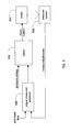
- FIG. 1 shows example components of an apparatus for respiratory flow estimation and pressure treatment based thereon
- FIG. 2 is a flow chart for a method for a pressure treatment or flow estimation apparatus of the present technology
- FIG. 3 is an illustrative input/output diagram for a control circuit or processor implementing flow estimation technology
- FIG. 4 is a graph of an exemplary pressure treatment waveform implemented by a pressure treatment apparatus utilizing the present flow estimation technology
- FIG. 5 is a diagram illustrating suitable components of a feedback control loop of a pressure treatment device utilizing flow estimation technology for mask swing adjustment.
- the present technology may be implemented with a pressure treatment delivery device that may include a flow generator such as a servo-controlled blower 102.
- the blower 102 will typically include an air inlet and impeller driven by a motor (not shown).
- a frequency sensor 104 is provided.
- the sensor may be configured to measure the rotational velocity of the blower.
- a tachometer may measure the revolutions per minute (RPM) of the blower's motor or the blower's impeller.
- the frequency sensor 104 may be configured to generate a frequency signal f(t) indicative of the measurements of the sensor.
- the device of FIG. 1 may further include a pressure sensor 106, such as a pressure transducer.
- the pressure sensor 106 is configured to measure the pressure generated by the blower 102.
- the pressure sensor 106 is proximate to the blower 102 but may be located downstream of the blower as desired.
- the pressure sensor 106 generates a pressure signal p(t) indicative of the measurements of pressure.
- the pressure sensor 106 and frequency sensor 104 have only been shown symbolically in FIG. 1 since it is understood that other configurations and other components may be implemented to measure the frequency and pressure associated with the blower 102.
- the pressure treatment delivery device will also typically include a patient interface such as an air delivery conduit 108 and a mask 110 to carry a flow of air or breathable gas to and/or from a patient.
- the blower 102 can be coupled with the air delivery conduit 108 and the mask 110 so as to provide the breathable gas from the blower 102.
- Exhaust gas can be vented from the patient interface via an exhaust 111.
- the frequency f(t) and pressure p(t) signals may be sent to a controller or processor 112.
- Optional analog-to-digital (A/D) converters/samplers may be utilized in the event that supplied signals from the frequency and pressure sensors are not in digital form and the controller is a digital controller.
- the controller may in turn generate blower control signals.
- the controller may generate an RPM request signal to control the speed of the blower 102 by setting a desired frequency or rotational velocity set point and comparing it with the measured condition of the frequency sensor.
- such changes may be based on determining a desired pressure set point and comparing it with the measured condition of the pressure sensor.
- such changes to the motor speed are accomplished by increasing or decreasing supplied motor current with the servo based on determined differences between set and measured conditions such as in a closed loop feedback fashion and translating the difference to current.
- the processor 112 or controller may make controlled changes to the pressure delivered to the patient interface by the blower 102.
- changes to pressure may be implemented by controlling the exhaust with a mechanical release valve (not shown) to increase or decrease the exhaust while maintaining a relatively constant blower speed.
- the controller or processor 112 is typically configured and adapted to implement particular control methodology such as the methods described in more detail herein.
- the controller may include integrated chips, a memory and/or other control instruction, data or information storage medium.
- programmed instructions encompassing such a control methodology may be coded on integrated chips in the memory of the device or such instructions may be loaded as software or firmware using an appropriate medium.
- the apparatus can be used for many different pressure treatment therapies, such as the pressure treatments previously mentioned, by adjusting a pressure delivery equation that is used to set the speed or pressure of the blower or the exhaust venting by the release valve.
- an embodiment of the system may determine or estimate a patient respiratory flow, even without a flow signal from a flow sensor, and then adjust the pressure treatment delivered by the device based on patient respiratory conditions detected from or with the estimated flow signal. While the flow characteristics of the hose to the mask may also impact pressure determinations, such a flow estimation model can be based on the premise that in an rpm-controlled system the load perturbations (i.e., patient respiratory flow) are reflected in the pressure output of the device. Similarly, in a pressure-controlled system the load perturbations will be reflected in the rpm output of the device.
- two measures such as pressure and flow generator system frequency (e.g., a rotational velocity of the blower such as RPM) taken together can give a measure of flow.
- the measured pressure and an expected pressure value derived from the frequency measure may both be utilized to derive the flow as a function thereof. This can be illustrated with the following function:
- P RPM_derived may be determined or calculated by a static fan curve as follows:
- the flow may then be determined as a function of the difference between P M and P RPM_derived by utilizing the following equation:
- a look up table may be pre-formed based on the above equations.
- a suitable table may be pre-calculated based on a range of input measures of frequency and a range of input measures of pressure using the formulas.
- the output of the table would then be a derived instantaneous flow value based on an input instantaneous measure of pressure and an input instantaneous measure of frequency as previously described.
- the derived flow values may be determined from the difference between the measured pressure and the frequency derived pressure (e.g., P M - P RPM_derived ).
- the flow may be more simply estimated by the following equation:
- the above determined flow values may be further processed to separate the system or leak flow from the patient respiratory flow by a suitable operation such as one illustrated by the following equation:
- FIG. 3 illustrates the flow estimate methodology with respect to a controller or processor 312.
- a measured pressure value signal 302 (p(t)) and a measured frequency value signal 304 ( ⁇ (t)) are input to a flow estimate algorithm 306 for deriving an estimated flow value signal 308.
- the flow estimate algorithm 306 is based on any of the calculations or functions as previously discussed such as one or more flow lookup tables 330.
- An estimate of flow (e.g., estimated patient respiratory flow) made by any of the methods discussed herein may then be used in any suitable flow-based determinations typically made by a pressure treatment device.
- the derived flow estimate can be used to make a change in pressure upon detection of features of the patient respiratory cycle.
- the derived flow estimate may be used to trigger an expiratory pressure relief.
- a ratiometric trigger threshold such as a trigger threshold that is a function of the peak respiratory flow, may be utilized to detect the onset of expiration. Utilizing such a trigger in particular combination with any of the above estimates of flow that might deviate marginally from actual patient flow provides for a more reliable or resilient respiratory cycle detection and appropriate pressure response.
- a bi-level pressure treatment therapy may be generated such that a reduced pressure level is delivered by the EPR during patient expiration and a higher treatment pressure level without the EPR reduction is delivered during patient inspiration.
- the changes between an inspiratory level and an expiratory level may be gradual such that a smoother pressure change between the inspiratory pressure treatment levels and the expiratory pressure treatments may be effected.
- FIG. 4 includes a plot of a patient simulation flow waveform 402 that has been generated by a patient flow simulation apparatus.
- the patient flow simulation apparatus was coupled with the patient interface of a pressure treatment device that implements flow estimation technology described herein.
- FIG. 4 also includes a graph of a pressure waveform 404 generated using the flow estimation and triggering technology discussed herein within the pressure treatment device. The graph illustrates that the device may deliver pressure adjustment in synchrony with the cycle of the patient simulation flow waveform 402 based on the estimated flow methodology.
- a pressure treatment device can be affected by changes to pressure in the system introduced by the patient's respiratory cycle.
- the sensors utilized for control of pressure levels to the mask of the patient interface are located proximate to the flow generator, rather than the mask of the patient interface, undesirable swings in mask pressure can be induced by the patient's respiration. These undesirable mask pressure swings can be adjusted with the controller to maintain more steady pressure levels by utilizing the present estimated patient flow technology.
- the pressure treatment device controls pressure rather than controlling motor rpm and a pressure sensor used for the control is located at or proximate to the flow generator.
- the measure of pressure that will be used in the feedback loop for pressure control is adjusted as a function of the estimate of flow. This adjustment is implemented in a predictive manner in an effort to impede mask swings induced by the patient's respiratory cycle.
- the measured control pressure may be adjusted according to the following method:
- MeasuredPressure adjusted MeasuredPressure - FlowFactor
- this function of the estimate of flow may be multiplying the estimate by a value K, where K is a value that is different for positive flow (e.g., patient inspiration) and than for negative flow (e.g., patient expiration).
- K is a value that is different for positive flow (e.g., patient inspiration) and than for negative flow (e.g., patient expiration).
- the value for K may be experimentally chosen for positive and negative flow as desired to identify optimum values for swing reduction that generate more steady mask pressure in response to patient respiration.
- Controller components of such swing compensation control are illustrated in FIG. 5 .
- An estimated flow value or signal is supplied to a measured pressure adjustor 550 along with a pressure value or signal measured by a pressure sensor 556.
- a pressure setting value or signal is supplied to the servo 552 along with an adjusted measured pressure value or signal. Based on these signals, the servo adjusts the motor current for controlling the output or speed of the motor 554 of the flow generator to thereby adjust the pressure delivered by the flow generator device to predictively reduce mask pressure swings induced by patient respiration.
- swing compensation control may be implemented with a modified version of the swing control equation.
- the pressure at the flow generator is controlled by comparing a desired pressure set point with the measurement from the pressure sensor.
- the flow generator may be controlled so that a pressure set point is equal to a measure of pressure determined from a pressure sensor at the flow generator.
- MaskPress PresSetPoint - PresLossInDeliveryCircuit
- PresSetPoint is a desired pressure or target pressure
- PresLossInDeliveryCircuit is a pressure loss due to the impedance of the delivery circuit.
- MeasuredPressure adjusted P M - FlowFactor
- P M is a measure of pressure from a sensor such as a pressure transducer.
- the FlowFactor may represent the pressure drop in the delivery circuit and can be assumed to be proportional to an estimate of flow. For example,
- ImpedOfDeliveryCir is the impedance of the delivery circuit or patient interface
- Flow is an estimate of flow as previously determined.
- Flow PresDropAcrossTurbine / ImpedanceOfTurbine ; where PresDropAcrossTurbine is a pressure drop across the flow generator such as one determined as a difference between a measured pressure and a derived pressure as previously described (e.g., P M - P RPM_derived ), and ImpedanceofTurbine is an impedance of the flow generator which may depend on the particular design of the flow generator and may be predetermined and/or preset into the memory of the controller of the system.
- PresDropAcrossTurbine is a pressure drop across the flow generator such as one determined as a difference between a measured pressure and a derived pressure as previously described (e.g., P M - P RPM_derived )
- ImpedanceofTurbine is an impedance of the flow generator which may depend on the particular design of the flow generator and may be predetermined and/or preset into the memory of the controller of the system.
- K is a ratio of two impedances such as ImpedOfDeliveryCircuit divided by the ImpedanceOfTurbine.
- Such an equation may then be implemented for swing compensation control in a pressure treatment delivery device of the present technology by controlling the respiratory treatment apparatus to generate pressure so that the adjusted measure of pressure meets a target or desired pressure setting.
- the flow estimate technology may be implemented in a system utilized for detecting patient flow limitation or making other adjustments to the delivered treatment pressure of a pressure treatment device.
- the flow estimate may be utilized in systems having a flow sensor.
- the flow estimate technology described herein may serve as back up flow determination in the event of failure of a flow sensor that is used for flow based determinations.
- the estimate of flow data may be combined with data from a flow sensor to generate combined flow data to insulate the system from more transient errors in either the flow signal from the flow sensor or the derived estimate of flow described herein.
- Example implementations of the aforementioned technology may include any of the embodiments, or modifications thereof, as illustrated in following paragragphs.
- a method for a respiratory flow generating apparatus comprising:
- deriving comprises determining an expected pressure as a function of the measure of frequency.
- deriving comprises calculating a difference between the determined expected pressure and the measure of pressure.
- a method of any of the preceding paragraphs further comprising delivering pressure by the respiratory flow generating apparatus as a function of the derived estimate of respiratory flow.
- a method of any of the preceding paragraphs wherein the function of the derived estimate of respiratory flow comprises determining a peak value of the derived estimate of respiratory flow.
- a method of any of the preceding paragraphs wherein the delivering the pressure by the respiratory flow generating apparatus comprises triggering an expiratory pressure relief.
- a method of any of the preceding paragraphs further comprising adjusting a pressure delivered by the respiratory flow generating apparatus to compensate for a patient induced swing at a patient interface, wherein the adjusting is based on the derived estimate of patient respiratory flow.
- An apparatus for generating respiratory flow comprising:
- deriving comprises determining an expected pressure as a function of the measure of frequency.
- deriving comprises calculating a difference between the determined expected pressure and the measure of pressure.
- processor is further configured to control a generation of pressure with the flow generator as a function of the derived estimate of respiratory flow.
- An apparatus of any of the preceding paragraphs wherein the function of the derived estimate of respiratory flow comprises determining a peak value of the derived estimate of respiratory flow.
- control of the generation of pressure with the flow generator comprises triggering an expiratory pressure relief.
- the processor controls adjusting a pressure delivered by the flow generator to compensate for a patient induced swing at the patient interface, wherein the adjusting is based on the derived estimate of patient respiratory flow.
- a system for delivering respiratory flow to a patient comprising:
- deriving comprises determining an expected pressure as a function of the measure of frequency.
- deriving comprises calculating a difference between the determined expected pressure and the measure of pressure.
- processing means is further configured for controlling a generation of pressure with the flow means as a function of the derived estimate of respiratory flow.
- a system of any of the preceding paragraphs wherein the function of the derived estimate of respiratory flow comprises determining a peak value of the derived estimate of patient respiratory flow.
- controlling the generation of pressure with the flow means comprises triggering an expiratory pressure relief.
- An information-bearing medium of any of the preceding paragraphs wherein the deriving comprises determining an expected pressure as a function of the measure of frequency.
- An information-bearing medium of any of the preceding paragraphs wherein the deriving comprises calculating a difference between the determined expected pressure and the measure of pressure.
- An information-bearing medium of any of the preceding paragraphs further comprising delivering pressure by the flow generator as a function of the derived estimate of respiratory flow.
- An information-bearing medium of any of the preceding paragraphs wherein the function of the derived estimate of respiratory flow comprises determining a peak value of the derived estimate of respiratory flow.
- An information-bearing medium of any of the preceding paragraphs wherein a change in pressure is generated in synchrony with a patient's respiratory cycle without a measure of the patient's respiratory flow from a flow sensor.
- a method of controlling pressure in a pressure treatment delivery apparatus to compensate for patient induced swing at a patient interface comprising:
- the measure of pressure drop is a difference between a measure of pressure and a derived measure of pressure that is a determined function of a frequency of the flow generator.
- a pressure treatment delivery apparatus to compensate for patient induced swing comprising:
- a pressure treatment delivery system to compensate for patient induced swing comprising:
- An information-bearing medium having processor-readable information thereon, the processor-readable information to control an apparatus for providing pressure treatment therapy to compensate for patient induced swing, the processor-readable information comprising control instructions to:
- the measure of pressure drop is a difference between a measure of pressure and a derived measure of pressure that is a determined function of a frequency of the flow generator.
Abstract
Description
- This application claims the benefit of the filing dates of United States Provisional Patent Application Nos.
60/965,171 filed August 17, 2007 61/125,066 filed April 22, 2008 - The present technology relates to methods and apparatus for treatment of respiratory conditions such as the conditions related to obstructive sleep apnea hypopnea syndrome (OSAHS) or obstructive sleep apnea (OSA).
- Patients with OSA have recurrent apnoeas or hypopnoeas during sleep that are only terminated by the patient arousing. These recurrent events cause sleep fragmentation and stimulation of the sympathetic nervous system. This can have severe consequences for the patient including day-time sleepiness (with the attendant possibility of motor-vehicle accidents), poor mentation, memory problems, depression and hypertension. Patients with OSA are also likely to snore loudly, thus also disturbing their partner's sleep. The best form of treatment for patients with OSA is constant positive airway pressure (CPAP) applied by a blower (compressor) via a connecting hose and mask (patient interface). The positive pressure prevents collapse of the patient's airway during inspiration, thus preventing recurrent apnoeas or hypopnoeas and their sequelae.
- Positive airway pressure may be delivered in many forms. For example, a positive pressure level may be maintained across the inspiratory and expiratory levels of the patient's breathing cycle at an approximately constant level. Alternatively, pressure levels may be adjusted to change synchronously with the patient's breathing cycle. For example, pressure may be set at one level during inspiration and another lower level during expiration for patient comfort. Such a pressure treatment system may be referred to as bi-level. Alternatively, the pressure levels may be continuously adjusted to smoothly replicate changes in the patient's breathing cycle. A lower pressure setting during expiration may generally be referred to as expiratory pressure relief.
- In providing such changes to pressure and/or detecting conditions for making adjustments to the treatment pressure, it can be helpful to have a measure of patient respiratory flow. For example, a measure of patient respiratory flow may be utilized to detect when a patient changes from inspiration to expiration for determining when to deliver expiratory pressure treatment settings or inspiratory pressure treatment settings. Similarly, a measured patient respiratory flow signal may be utilized to detect patient flow limitation for purposes of making treatment pressure adjustments. Such adjustments are illustrated in the patent in
U.S. Patent No. 5,704,345 . For these purposes, a measured flow signal may be derived from a flow sensor such as a differential pressure transducer or pnuemotachograph. - It may be desirable to develop further methods and devices for estimating flow to improve existing methods and devices and/or to develop new pressure treatment and detection methods and devices.
- Aspects of the present technology involve methods for a respiratory flow generating apparatus. In one method, a measure of pressure produced by a respiratory flow generating apparatus and a measure of a frequency of the respiratory flow generating apparatus are determined. The method then derives an estimate of patient respiratory flow as a function of the measure of pressure and the measure of frequency. In some embodiments, the measure of frequency may be a rotational velocity. Moreover, the deriving of the estimate may further include determining an expected pressure as a function of the measure of frequency and may further include calculating a difference between the determined expected pressure and the measure of pressure. Pressure treatment by the respiratory flow generating apparatus may be set or adjusted as a function of the derived estimate of respiratory flow.
- In one embodiment, the technology encompasses an apparatus for generating respiratory flow. The apparatus may optionally include a patient interface to carry a flow of breathable gas to a patient. The apparatus may further include a flow generator coupled with the patient interface to generate a flow of the breathable gas through the patient interface. The apparatus may also include measurement sensors such as a pressure transducer to provide a pressure signal indicative of pressure in a portion of the patient interface or associated with the flow generator and a tachometer to provide a velocity signal indicative of a speed of the flow generator. The apparatus may also be provided with a controller to control the flow generator. The controller is coupled with the pressure transducer to process the pressure signal and it is coupled with the tachometer to process the velocity signal. The controller may be configured and adapted to control a method for estimating patient respiratory flow or to set delivered treatment pressure by a method as described herein such as by determining a measure of pressure with the pressure signal, determining a measure of frequency with the velocity signal and deriving an estimate of patient respiratory flow as a function of the measure of pressure and the measure of frequency.
- In a further embodiment, a system for delivering respiratory flow to a patient includes an interface means to carry a flow of breathable gas. The system may also include a flow means, coupled with the interface means, for generating the breathable gas. The system may have a pressure sensing means for measuring pressure and for generating a pressure signal representing the measured pressure of the breathable gas as well as a frequency sensing means for measuring a frequency of the flow means and for generating a frequency signal representing the measured frequency. The system will typically also include a processing means for processing the pressure signal and the frequency signal. The processing means may be configured or adapted for processing a determination of a measure of pressure with the pressure signal, a determination of a measure of frequency with the frequency signal and a derivation of an estimate of patient respiratory flow as a function of the measure of pressure and the measure of frequency. The processing means may also be configured for controlling a generation of pressure with the flow means as a function of the derived estimate of respiratory flow. In an embodiment of the system, changes to pressure treatment may be delivered in synchrony with a patient's respiratory cycle without a flow sensor or utilizing a signal from a flow sensor.
- In another embodiment, methodology of the technology may be encoded on an information-bearing medium as software or firmware. For example, an information-bearing medium may include processor-readable information or processor control instructions. The processor-readable information may control an apparatus for providing pressure treatment therapy. The processor-readable information or processor control instructions may include steps that implement determining a measure of pressure produced by a flow generator, determining a measure of frequency of the flow generator and deriving an estimate of patient respiratory flow as a function of the measure of pressure and the measure of frequency.
- Further embodiments and features of the technology will be apparent from the following detailed disclosure, claims and drawings.
- The present technology is illustrated by way of example, and not by way of limitation, in the figures of the accompanying drawings, in which like reference numerals refer to similar elements including:
-
FIG. 1 shows example components of an apparatus for respiratory flow estimation and pressure treatment based thereon; -
FIG. 2 is a flow chart for a method for a pressure treatment or flow estimation apparatus of the present technology; -
FIG. 3 is an illustrative input/output diagram for a control circuit or processor implementing flow estimation technology; -
FIG. 4 is a graph of an exemplary pressure treatment waveform implemented by a pressure treatment apparatus utilizing the present flow estimation technology; -
FIG. 5 is a diagram illustrating suitable components of a feedback control loop of a pressure treatment device utilizing flow estimation technology for mask swing adjustment. - In reference to
FIG. 1 , the present technology may be implemented with a pressure treatment delivery device that may include a flow generator such as a servo-controlledblower 102. Theblower 102 will typically include an air inlet and impeller driven by a motor (not shown). - In the embodiment illustrated in
FIG. 1 , afrequency sensor 104 is provided. The sensor may be configured to measure the rotational velocity of the blower. For example, a tachometer may measure the revolutions per minute (RPM) of the blower's motor or the blower's impeller. Thefrequency sensor 104 may be configured to generate a frequency signal f(t) indicative of the measurements of the sensor. - The device of
FIG. 1 may further include apressure sensor 106, such as a pressure transducer. Thepressure sensor 106 is configured to measure the pressure generated by theblower 102. In this embodiment, thepressure sensor 106 is proximate to theblower 102 but may be located downstream of the blower as desired. Thepressure sensor 106 generates a pressure signal p(t) indicative of the measurements of pressure. Thepressure sensor 106 andfrequency sensor 104 have only been shown symbolically inFIG. 1 since it is understood that other configurations and other components may be implemented to measure the frequency and pressure associated with theblower 102. - The pressure treatment delivery device will also typically include a patient interface such as an
air delivery conduit 108 and amask 110 to carry a flow of air or breathable gas to and/or from a patient. Theblower 102 can be coupled with theair delivery conduit 108 and themask 110 so as to provide the breathable gas from theblower 102. Exhaust gas can be vented from the patient interface via anexhaust 111. - The frequency f(t) and pressure p(t) signals may be sent to a controller or
processor 112. Optional analog-to-digital (A/D) converters/samplers (not shown separately) may be utilized in the event that supplied signals from the frequency and pressure sensors are not in digital form and the controller is a digital controller. Based on input signals from these sensors and/or other optional sensors, the controller may in turn generate blower control signals. For example, the controller may generate an RPM request signal to control the speed of theblower 102 by setting a desired frequency or rotational velocity set point and comparing it with the measured condition of the frequency sensor. Alternatively, such changes may be based on determining a desired pressure set point and comparing it with the measured condition of the pressure sensor. Typically, such changes to the motor speed are accomplished by increasing or decreasing supplied motor current with the servo based on determined differences between set and measured conditions such as in a closed loop feedback fashion and translating the difference to current. Thus, theprocessor 112 or controller may make controlled changes to the pressure delivered to the patient interface by theblower 102. Optionally, such changes to pressure may be implemented by controlling the exhaust with a mechanical release valve (not shown) to increase or decrease the exhaust while maintaining a relatively constant blower speed. - The controller or
processor 112 is typically configured and adapted to implement particular control methodology such as the methods described in more detail herein. Thus, the controller may include integrated chips, a memory and/or other control instruction, data or information storage medium. For example, programmed instructions encompassing such a control methodology may be coded on integrated chips in the memory of the device or such instructions may be loaded as software or firmware using an appropriate medium. With such a controller or processor, the apparatus can be used for many different pressure treatment therapies, such as the pressure treatments previously mentioned, by adjusting a pressure delivery equation that is used to set the speed or pressure of the blower or the exhaust venting by the release valve. - For example, based on such a configuration, an embodiment of the system may determine or estimate a patient respiratory flow, even without a flow signal from a flow sensor, and then adjust the pressure treatment delivered by the device based on patient respiratory conditions detected from or with the estimated flow signal. While the flow characteristics of the hose to the mask may also impact pressure determinations, such a flow estimation model can be based on the premise that in an rpm-controlled system the load perturbations (i.e., patient respiratory flow) are reflected in the pressure output of the device. Similarly, in a pressure-controlled system the load perturbations will be reflected in the rpm output of the device.
- Thus, in one embodiment, two measures, such as pressure and flow generator system frequency (e.g., a rotational velocity of the blower such as RPM) taken together can give a measure of flow. In one suitable patient flow estimate, the measured pressure and an expected pressure value derived from the frequency measure may both be utilized to derive the flow as a function thereof. This can be illustrated with the following function:
-

- Where:
- PM is a measured pressure;
- PRPM_derived is an expected pressure at a particular flow that is determined or calculated from a measured system variable other than pressure such as frequency or rotational velocity (e.g., RPM) of the blower. Depending on the flow generator characteristics and required accuracy, it can also be either a fixed value or calibrated value.
- In one embodiment, PRPM_derived may be determined or calculated by a static fan curve as follows:
-

- Where:
- ω is an angular frequency of the flow generator (which may also be referred to as angular speed, radial frequency, and radian frequency); and
- K2, K1 and K0 may be experimentally pre-determined constants for relating an experimental measure of delivered pressure to a blower's measured angular frequency based on the particular structural characteristics of the flow generator or blower (e.g., impeller design). Optionally, in the case of small constants, the constants may be uniformly scaled up to reduce operational overhead of decimal point operations on a device's processor or controller.
- In one embodiment, the flow may then be determined as a function of the difference between PM and PRPM_derived by utilizing the following equation:
-

- Where:
- x is PM minus PRPM_derived as previously described; and
- A3, A2, A1 and A0 may be experimentally pre-determined constants for relating an experimental measure of flow to a function of the blower's measured angular frequency and measured pressure based on the particular structural characteristics of the system.
- However, given the limitations of 32-bit processing, it was found that the computational complexity was quite high for arriving at the desired level of performance of flow linearization using the above equation. Thus, in another embodiment of the technology, in order to simplify the determination, a look up table may be pre-formed based on the above equations. A suitable table may be pre-calculated based on a range of input measures of frequency and a range of input measures of pressure using the formulas. The output of the table would then be a derived instantaneous flow value based on an input instantaneous measure of pressure and an input instantaneous measure of frequency as previously described.
- In a still further embodiment of the technology, the derived flow values may be determined from the difference between the measured pressure and the frequency derived pressure (e.g., PM - PRPM_derived). Thus, the flow may be more simply estimated by the following equation:
-

- Where:
- PM is a measured pressure; and
- PRPM_derived is an expected pressure that is determined or calculated from a measured system variable other than pressure such as frequency or rotational velocity (e.g., RPM or ω) of the blower by any method previously discussed.
- [0] Although this particular estimate is not linearized, it can give an estimate of flow excursion. Therefore, it is quite suitable for algorithms that are dependent on cycle detection. In the absence of further processing, it may not alone be highly suitable for algorithms that require more accurate flow value or more accurate flow shape. However, its simplicity can make it particularly suitable for implementation either as a hardware component to reduce a system processor load or as firmware/software for a system processor.
- In a system that employs a continuous system exhaust flow or leak with which the patient respiratory flow is combined, the above determined flow values may be further processed to separate the system or leak flow from the patient respiratory flow by a suitable operation such as one illustrated by the following equation:
-

- Where:
- FLW is continuously or periodically determined flow values derived from any of the previously described methods; and
- LPF(FLW) is a low pass filtering operation on the flow values with the filtering operation being chosen to remove a constant component of the flow that can be associated with a relatively constant leak or system flow. An example operation may be low pass filtering with a time constant of 10 seconds.
-
FIG. 3 illustrates the flow estimate methodology with respect to a controller orprocessor 312. A measured pressure value signal 302 (p(t)) and a measured frequency value signal 304 (ω(t)) are input to aflow estimate algorithm 306 for deriving an estimatedflow value signal 308. Theflow estimate algorithm 306 is based on any of the calculations or functions as previously discussed such as one or more flow lookup tables 330. - An estimate of flow (e.g., estimated patient respiratory flow) made by any of the methods discussed herein may then be used in any suitable flow-based determinations typically made by a pressure treatment device. For example, the derived flow estimate can be used to make a change in pressure upon detection of features of the patient respiratory cycle. In an illustrative embodiment, the derived flow estimate may be used to trigger an expiratory pressure relief. In such an embodiment, a ratiometric trigger threshold, such as a trigger threshold that is a function of the peak respiratory flow, may be utilized to detect the onset of expiration. Utilizing such a trigger in particular combination with any of the above estimates of flow that might deviate marginally from actual patient flow provides for a more reliable or resilient respiratory cycle detection and appropriate pressure response.
- In this embodiment, the technology can be implemented according to the following pseudo code:
     if (RespiratoryFlow > PeakRespiratoryFlow/Y) or
     (EPR has been on for over 15 sec) then
          Turn EPR off
     else if (RespiratoryFlow < 0) then
          Turn EPR on
- RespiratoryFlow is a derived flow estimate made by any of the methods previously described;
- PeakRespiratoryFlow is a pre-peak respiratory flow value, such as a peak determined in a prior respiratory cycle;
- Y is some divisor of the peak respiratory flow (e.g., 4); and
- EPR is a procedure that implements a reduction in the delivered treatment pressure setting for patient comfort.
- FlowFactor is a function of an estimate of flow determined by any of the previously described methods.
- DesiredPressure is a determined treatment pressure setting such as an inspiratory or expiratory treatment pressure level;
- MeasuredPressureadjusted is the adjusted pressure as previously described;
- P and I are factors chosen for translation of the pressure setting to an adjustment of the current applied to the motor of the flow generator for adjusting a particular motor's speed based on the characteristics of the motor.
Where:
MaskPres is the pressure in the patient mask or patient interface,
PresSetPoint is a desired pressure or target pressure,
PresLossInDeliveryCircuit is a pressure loss due to the impedance of the delivery circuit.
where
PM is a measure of pressure from a sensor such as a pressure transducer.
The FlowFactor may represent the pressure drop in the delivery circuit and can be assumed to be proportional to an estimate of flow. For example,
where
PresDropAcrossTurbine is a pressure drop across the flow generator such as one determined as a difference between a measured pressure and a derived pressure as previously described (e.g., PM - PRPM_derived), and
ImpedanceofTurbine is an impedance of the flow generator which may depend on the particular design of the flow generator and may be predetermined and/or preset into the memory of the controller of the system.

where
- determining a measure of pressure produced by a respiratory flow generating apparatus;
- determining a measure of a frequency of the respiratory flow generating apparatus; and
- deriving an estimate of patient respiratory flow as a function of the measure of pressure and the measure of frequency.
- a patient interface to carry a flow of breathable gas to a patient;
- a flow generator coupled with the patient interface to generate a flow of the breathable gas through the patient interface;
- a pressure transducer to provide a pressure signal indicative of pressure associated with the flow generator;
- a tachometer to provide a velocity signal indicative of a speed of the flow generator; and
- a processor to control the flow generator, the processor coupled with the pressure transducer to process the pressure signal and coupled with the tachometer to process the velocity signal, the processor being configured to control:
- determining a measure of pressure with the pressure signal;
- determining a measure of frequency with the velocity signal; and
- deriving an estimate of patient respiratory flow as a function of the measure of pressure and the measure of frequency.
- an interface means to carry a flow of breathable gas;
- a flow means, coupled with the interface means, for generating the breathable gas;
- a pressure sensing means for measuring pressure and for generating a pressure signal representing the measured pressure of the breathable gas;
- a frequency sensing means for measuring a frequency of the flow means and for generating a frequency signal representing the measured frequency;
- a processing means for processing the pressure signal and the frequency signal, the processing means being configured for processing:
- (a) determining a measure of pressure with the pressure signal;
- (b) determining a measure of frequency with the frequency signal; and
- (c) deriving an estimate of patient respiratory flow as a function of the measure of pressure and the measure of frequency.
- determining a measure of pressure produced by a flow generator;
- determining a measure of frequency of the flow generator; and
- deriving an estimate of patient respiratory flow as a function of the measure of pressure and the measure of frequency.
- determining a measure of pressure delivered by a flow generator with a pressure sensor, the pressure sensor being located proximate to the flow generator;
- adjusting the measure of pressure as a function of (a) a measure of pressure drop across the flow generator, (b) a measure of impedance of a patient interface coupled to the flow generator and (c) a measure of impedance of the flow generator; and
- controlling the flow generator so that the adjusted measure of pressure satisfies a target pressure setting.
- a patient interface to carry a flow of breathable gas to a patient;
- a flow generator coupled with the patient interface to generate a flow of the breathable gas through the patient interface;
- a pressure sensor to provide a pressure signal indicative of pressure associated with the flow generator; and
- a processor to control the flow generator, the processor coupled with the pressure sensor to process the pressure signal, the processor being configured to control:
- determining a measure of pressure delivered by a flow generator with the pressure sensor, the pressure sensor being located proximate to the flow generator;
- adjusting the measure of pressure as a function of (a) a measure of pressure drop across the flow generator, (b) a measure of impedance of a patient interface and (c) a measure of impedance of the flow generator; and
- controlling the flow generator so that the adjusted measure of pressure satisfies a target pressure setting.
- a patient interface means for carrying a flow of breathable gas to a patient;
- a flow generation means coupled with the patient interface for generating a flow of the breathable gas through the patient interface;
- a sensor means for providing a pressure signal indicative of pressure associated with the flow generator; and
- a control means, coupled with the sensor means and flow generation means, for determining a measure of pressure delivered by the flow generation means, for adjusting the measure of pressure as a function of (a) a measure of pressure drop across the flow generator, (b) a measure of impedance of a patient interface and (c) a measure of impedance of the flow generator, and for controlling the flow generator so that the adjusted measure of pressure satisfies a target pressure setting.
- determine a measure of pressure delivered by a flow generator with a pressure sensor that is located proximate to the flow generator;
- adjust the measure of pressure as a function of (a) a measure of pressure drop across the flow generator, (b) a measure of impedance of a patient interface coupled to the flow generator and (c) a measure of impedance of the flow generator; and
- control the flow generator so that the adjusted measure of pressure satisfies a target pressure setting.
Claims (15)
- An apparatus for generating respiratory flow comprising:a patient interface to carry a flow of breathable gas to a patient;a flow generator coupled with the patient interface to generate a flow of the breathable gas through the patient interface;a pressure transducer to provide a pressure signal indicative of pressure associated with the flow generator;a tachometer to provide a velocity signal indicative of a speed of the flow generator; anda processor to control the flow generator, the processor coupled with the pressure transducer to process the pressure signal and coupled with the tachometer to process the velocity signal, the processor being configured to control:determining a measure of pressure with the pressure signal;determining a measure of frequency with the velocity signal; andderiving an estimate of patient respiratory flow as a function of the measure of pressure and the measure of frequency.
- The apparatus of claim 1 wherein the measure of frequency is a rotational velocity.
- The apparatus of claim 1 wherein the deriving comprises determining an expected pressure as a function of the measure of frequency.
- The apparatus of claim 3 wherein the deriving comprises calculating a difference between the determined expected pressure and the measure of pressure.
- The apparatus of claim 1 wherein the processor is further configured to control a generation of pressure with the flow generator as a function of the derived estimate of respiratory flow.
- The apparatus of claim 5 wherein the function of the derived estimate of respiratory flow comprises determining a peak value of the derived estimate of respiratory flow.
- The apparatus of claim 6 wherein the control of the generation of pressure with the flow generator comprises triggering an expiratory pressure relief.
- The apparatus of claim 5 wherein changes in pressure are delivered in synchrony with a patient's respiratory cycle without a measure of the patient's respiratory flow from a flow sensor.
- The apparatus of claim 1 wherein the processor controls adjusting a pressure delivered by the flow generator to compensate for a patient induced swing at the patient interface, wherein the adjusting is based on the derived estimate of patient respiratory flow.
- A method of operating a respiratory flow generating apparatus wherein the apparatus includes:a patient interface to carry a flow of breathable gas to a patient;a flow generator coupled with the patient interface to generate a flow of the breathable gas through the patient interface;a pressure transducer to provide a pressure signal indicative of pressure associated with the flow generator;a tachometer to provide a velocity signal indicative of a speed of the flow generator; anda processor to control the flow generator, the processor coupled with the pressure transducer to process the pressure signal and coupled with the tachometer to process the velocity signal, the processor being configured to control:determining a measure of pressure with the pressure signal;determining a measure of frequency with the velocity signal; andderiving an estimate of patient respiratory flow as a function of the measure of pressure and the measure of frequency.
- A method for a respiratory flow generating apparatus comprising:determining a measure of pressure produced by a respiratory flow generating apparatus;determining a measure of a frequency of the respiratory flow generating apparatus; andderiving an estimate of patient respiratory flow as a function of the measure of pressure and the measure of frequency.
- A system for delivering respiratory flow to a patient comprising:an interface means to carry a flow of breathable gas;a flow means, coupled with the interface means, for generating the breathable gas;a pressure sensing means for measuring pressure and for generating a pressure signal representing the measured pressure of the breathable gas;a frequency sensing means for measuring a frequency of the flow means and for generating a frequency signal representing the measured frequency;a processing means for processing the pressure signal and the frequency signal, the processing means being configured for processing:(a) determining a measure of pressure with the pressure signal;(b) determining a measure of frequency with the frequency signal; and(c) deriving an estimate of patient respiratory flow as a function of the measure of pressure and the measure of frequency.
- An information-bearing medium having processor-readable information thereon, the processor-readable information to control an apparatus for providing pressure treatment therapy, the processor-readable information comprising:determining a measure of pressure produced by a flow generator;determining a measure of frequency of the flow generator; andderiving an estimate of patient respiratory flow as a function of the measure of pressure and the measure of frequency.
- A method of controlling pressure in a pressure treatment delivery apparatus to compensate for patient induced swing at a patient interface, the method comprising:determining a measure of pressure delivered by a flow generator with a pressure sensor, the pressure sensor being located proximate to the flow generator;adjusting the measure of pressure as a function of (a) a measure of pressure drop across the flow generator, (b) a measure of impedance of a patient interface coupled to the flow generator and (c) a measure of impedance of the flow generator; andcontrolling the flow generator so that the adjusted measure of pressure satisfies a target pressure setting.
- A pressure treatment delivery apparatus to compensate for patient induced swing comprising:a patient interface to carry a flow of breathable gas to a patient;a flow generator coupled with the patient interface to generate a flow of the breathable gas through the patient interface;a pressure sensor to provide a pressure signal indicative of pressure associated with the flow generator; anda processor to control the flow generator, the processor coupled with the pressure sensor to process the pressure signal, the processor being configured to control:determining a measure of pressure delivered by a flow generator with the pressure sensor, the pressure sensor being located proximate to the flow generator;adjusting the measure of pressure as a function of (a) a measure of pressure drop across the flow generator, (b) a measure of impedance of a patient interface and (c) a measure of impedance of the flow generator; andcontrolling the flow generator so that the adjusted measure of pressure satisfies a target pressure setting.
Priority Applications (1)
| Application Number | Priority Date | Filing Date | Title |
|---|---|---|---|
| EP13154887.7A EP2594303B1 (en) | 2007-08-17 | 2008-08-13 | Apparatus for pressure therapy in the treatment of sleep disordered breathing |
Applications Claiming Priority (2)
| Application Number | Priority Date | Filing Date | Title |
|---|---|---|---|
| US96517107P | 2007-08-17 | 2007-08-17 | |
| US12506608P | 2008-04-22 | 2008-04-22 |
Related Child Applications (2)
| Application Number | Title | Priority Date | Filing Date |
|---|---|---|---|
| EP13154887.7A Division-Into EP2594303B1 (en) | 2007-08-17 | 2008-08-13 | Apparatus for pressure therapy in the treatment of sleep disordered breathing |
| EP13154887.7A Division EP2594303B1 (en) | 2007-08-17 | 2008-08-13 | Apparatus for pressure therapy in the treatment of sleep disordered breathing |
Publications (3)
| Publication Number | Publication Date |
|---|---|
| EP2025358A2 true EP2025358A2 (en) | 2009-02-18 |
| EP2025358A3 EP2025358A3 (en) | 2009-03-25 |
| EP2025358B1 EP2025358B1 (en) | 2016-04-13 |
Family
ID=39892258
Family Applications (2)
| Application Number | Title | Priority Date | Filing Date |
|---|---|---|---|
| EP08014451.2A Active EP2025358B1 (en) | 2007-08-17 | 2008-08-13 | Methods and apparatus for pressure therapy in the treatment of sleep disordered breathing |
| EP13154887.7A Active EP2594303B1 (en) | 2007-08-17 | 2008-08-13 | Apparatus for pressure therapy in the treatment of sleep disordered breathing |
Family Applications After (1)
| Application Number | Title | Priority Date | Filing Date |
|---|---|---|---|
| EP13154887.7A Active EP2594303B1 (en) | 2007-08-17 | 2008-08-13 | Apparatus for pressure therapy in the treatment of sleep disordered breathing |
Country Status (6)
| Country | Link |
|---|---|
| US (2) | US9713690B2 (en) |
| EP (2) | EP2025358B1 (en) |
| JP (2) | JP2009148539A (en) |
| CN (3) | CN104524676B (en) |
| AU (2) | AU2008203812B2 (en) |
| NZ (4) | NZ583930A (en) |
Cited By (4)
| Publication number | Priority date | Publication date | Assignee | Title |
|---|---|---|---|---|
| EP2281593A1 (en) * | 2009-07-09 | 2011-02-09 | Dräger Medical GmbH | Medical blower control via pneumatic patient model |
| WO2011106246A1 (en) * | 2010-02-26 | 2011-09-01 | Nellcor Puritan Bennett Llc | A method for estimating at least one parameter at a patient circuit wye in a medical ventilator providing ventilation to a patient |
| US8113062B2 (en) | 2008-09-30 | 2012-02-14 | Nellcor Puritan Bennett Llc | Tilt sensor for use with proximal flow sensing device |
| US8528554B2 (en) | 2008-09-04 | 2013-09-10 | Covidien Lp | Inverse sawtooth pressure wave train purging in medical ventilators |
Families Citing this family (30)
| Publication number | Priority date | Publication date | Assignee | Title |
|---|---|---|---|---|
| US8021308B2 (en) | 2003-06-19 | 2011-09-20 | Capnia, Inc. | Breath end-tidal gas monitor |
| EP2106818B1 (en) * | 2008-03-31 | 2013-12-25 | Nellcor Puritan Bennett Llc | System for compensating for pressure drop in a breathing assistance system |
| US8181648B2 (en) * | 2008-09-26 | 2012-05-22 | Nellcor Puritan Bennett Llc | Systems and methods for managing pressure in a breathing assistance system |
| US8776790B2 (en) | 2009-07-16 | 2014-07-15 | Covidien Lp | Wireless, gas flow-powered sensor system for a breathing assistance system |
| CN102028996B (en) * | 2009-09-30 | 2012-09-05 | 北京谊安医疗系统股份有限公司 | Method and device for regulating output pressure of respirator decompressor |
| EP2496297B1 (en) * | 2009-11-03 | 2020-09-16 | ResMed Pty Ltd | Cpap systems |
| US20110253147A1 (en) * | 2010-04-19 | 2011-10-20 | Gusky Michael H | Breathing apparatus |
| CN102058922B (en) * | 2010-12-21 | 2014-05-14 | 上海力申科学仪器有限公司 | Control method of household breathing machine |
| JP6544925B2 (en) * | 2011-06-06 | 2019-07-17 | コーニンクレッカ フィリップス エヌ ヴェKoninklijke Philips N.V. | Configuration of mode of respiratory therapy |
| CN108132331A (en) | 2011-12-21 | 2018-06-08 | 卡普尼亚公司 | The gas of the exhalation of certain volume is collected and analyzed in the case where compensating respiration parameter frequency |
| EP3689406A1 (en) * | 2012-04-30 | 2020-08-05 | ResMed Pty Ltd | Apparatus for oral flow therapy |
| CA2897533A1 (en) | 2013-01-08 | 2014-07-17 | Capnia, Inc. | Breath selection for analysis |
| WO2014127044A1 (en) | 2013-02-12 | 2014-08-21 | Capnia, Inc. | Sampling and storage registry device for breath gas analysis |
| WO2014147514A1 (en) * | 2013-03-21 | 2014-09-25 | Koninklijke Philips N.V. | A gas delivery system including a flow generator employing a continuously variable transmission |
| CN110960772A (en) | 2013-07-01 | 2020-04-07 | 瑞思迈私人有限公司 | Motor drive system for breathing apparatus |
| WO2015031850A1 (en) | 2013-08-30 | 2015-03-05 | Capnia, Inc. | Neonatal carbon dioxide measurement system |
| WO2015058089A1 (en) | 2013-10-18 | 2015-04-23 | Silverbow Development Llc | Techniques for determining patient airway pressure |
| CN103977493B (en) * | 2014-05-29 | 2016-08-17 | 北京航空航天大学 | Can be used for the experiment porch of invasive ventilation gas leakage detection |
| CN107106799B (en) * | 2014-10-24 | 2020-11-27 | 瑞思迈公司 | Respiratory pressure therapy system |
| US9950129B2 (en) | 2014-10-27 | 2018-04-24 | Covidien Lp | Ventilation triggering using change-point detection |
| CN107029326A (en) * | 2015-07-30 | 2017-08-11 | 沈阳昌泰医疗科技有限公司 | A kind of breath signal decision algorithm for positive airway pressure machine |
| CN105854141B (en) * | 2016-05-05 | 2018-07-03 | 湖南明康中锦医疗科技发展有限公司 | A kind of respiratory triggering conversion method and device |
| US20170361041A1 (en) * | 2016-06-16 | 2017-12-21 | Loewenstein Medical Technology S.A. | Respirator for apap respiration using oscillatory pressure |
| EP3338843A1 (en) * | 2016-12-23 | 2018-06-27 | Löwenstein Medical Technology S.A. | Ventilation device with specification of a patient-specific pressure profile |
| CN109893736A (en) | 2017-12-07 | 2019-06-18 | 北京怡和嘉业医疗科技股份有限公司 | Data processing method and device based on positive airway pressure machine |
| CA3099804A1 (en) | 2018-05-14 | 2019-11-21 | Covidien Lp | Systems and methods for respiratory effort detection utilizing signal distortion |
| US11752287B2 (en) | 2018-10-03 | 2023-09-12 | Covidien Lp | Systems and methods for automatic cycling or cycling detection |
| CN112839696A (en) * | 2018-11-08 | 2021-05-25 | 深圳迈瑞生物医疗电子股份有限公司 | Respiration recognition method and device, ventilation equipment and storage medium |
| WO2022109424A1 (en) * | 2020-11-23 | 2022-05-27 | 8B Medical Llc | System and method for data collection, research, and proactive medical treatment |
| CN114469060A (en) * | 2021-12-31 | 2022-05-13 | 天津怡和嘉业医疗科技有限公司 | Breathing phase determination method and device |
Citations (3)
| Publication number | Priority date | Publication date | Assignee | Title |
|---|---|---|---|---|
| US5704345A (en) | 1993-11-05 | 1998-01-06 | Resmed Limited | Detection of apnea and obstruction of the airway in the respiratory system |
| EP1205203A2 (en) | 1994-10-14 | 2002-05-15 | Bird Products Corporation | Exhalation flow transducer |
| EP1393767A1 (en) | 2002-08-20 | 2004-03-03 | Gottlieb Weinmann Geräte für Medizin und Arbeitsschutz GmbH + Co. | Device and method for measuring a flow volume |
Family Cites Families (56)
| Publication number | Priority date | Publication date | Assignee | Title |
|---|---|---|---|---|
| DE3276924D1 (en) | 1981-04-24 | 1987-09-17 | Somed Pty Ltd | Device for treating snoring sickness |
| GB8704104D0 (en) | 1987-02-21 | 1987-03-25 | Manitoba University Of | Respiratory system load apparatus |
| US5390666A (en) * | 1990-05-11 | 1995-02-21 | Puritan-Bennett Corporation | System and method for flow triggering of breath supported ventilation |
| JP2582010B2 (en) | 1991-07-05 | 1997-02-19 | 芳嗣 山田 | Monitoring device for respiratory muscle activity |
| AUPM279393A0 (en) | 1993-12-03 | 1994-01-06 | Rescare Limited | Estimation of flow and detection of breathing in cpap treatment |
| DE4412328A1 (en) * | 1994-04-11 | 1995-10-19 | Bayer Ag | Heterocyclyl-1,3,4-thiadiazolyloxyacetamide |
| US5794615A (en) | 1994-06-03 | 1998-08-18 | Respironics, Inc. | Method and apparatus for providing proportional positive airway pressure to treat congestive heart failure |
| US6105575A (en) | 1994-06-03 | 2000-08-22 | Respironics, Inc. | Method and apparatus for providing positive airway pressure to a patient |
| US5535738A (en) * | 1994-06-03 | 1996-07-16 | Respironics, Inc. | Method and apparatus for providing proportional positive airway pressure to treat sleep disordered breathing |
| AU683753B2 (en) * | 1994-07-06 | 1997-11-20 | Teijin Limited | An apparatus for assisting in ventilating the lungs of a patient |
| US5551419A (en) | 1994-12-15 | 1996-09-03 | Devilbiss Health Care, Inc. | Control for CPAP apparatus |
| US5598838A (en) * | 1995-04-07 | 1997-02-04 | Healthdyne Technologies, Inc. | Pressure support ventilatory assist system |
| AUPN394895A0 (en) | 1995-07-03 | 1995-07-27 | Rescare Limited | Auto-calibration of pressure transducer offset |
| AUPN547895A0 (en) | 1995-09-15 | 1995-10-12 | Rescare Limited | Flow estimation and compenstion of flow-induced pressure swings cpap treatment |
| JP3845736B2 (en) * | 1995-09-18 | 2006-11-15 | レスメッド・リミテッド | Pressure control in CPAP treatment or assisted ventilation |
| AUPO247496A0 (en) | 1996-09-23 | 1996-10-17 | Resmed Limited | Assisted ventilation to match patient respiratory need |
| DE69839008D1 (en) | 1997-03-17 | 2008-03-06 | Vivometrics Inc | F INFLUENCE ON NEUROMUSCULAR BREATHING |
| WO1998051362A1 (en) | 1997-05-16 | 1998-11-19 | Peter Craig Farrell | Nasal ventilation as a treatment for stroke |
| FR2767466B1 (en) | 1997-08-25 | 1999-10-15 | Taema | METHOD FOR DETERMINING THE IMAGE OF A NASAL AND / OR ORAL RESPIRATORY FLOW OF A USER |
| AUPP026997A0 (en) | 1997-11-07 | 1997-12-04 | Resmed Limited | Administration of cpap treatment pressure in presence of apnea |
| AUPP366398A0 (en) | 1998-05-22 | 1998-06-18 | Resmed Limited | Ventilatory assistance for treatment of cardiac failure and cheyne-stokes breathing |
| AUPP370198A0 (en) * | 1998-05-25 | 1998-06-18 | Resmed Limited | Control of the administration of continuous positive airway pressure treatment |
| CN1241394A (en) | 1998-06-18 | 2000-01-19 | 塔埃玛 | Device for determining sleep respiratory cycle of user |
| US20030062045A1 (en) * | 1998-09-18 | 2003-04-03 | Respironics, Inc. | Medical ventilator |
| US7225809B1 (en) * | 1999-11-01 | 2007-06-05 | Ric Investments, Llc | Method and apparatus for monitoring and controlling a medical device |
| US7204250B1 (en) | 1999-12-16 | 2007-04-17 | Compumedics Limited | Bio-mask |
| EP1259157B1 (en) | 2000-03-02 | 2008-06-11 | Itamar Medical Ltd | Method and apparatus for the non-invasive detection of particular sleep-state conditions by monitoring the peripheral vascular system |
| GB0012871D0 (en) | 2000-05-27 | 2000-07-19 | British Aerospace | A relay test device |
| US6439229B1 (en) * | 2000-08-08 | 2002-08-27 | Newport Medical Instruments, Inc. | Pressure support ventilation control system and method |
| US6752151B2 (en) | 2000-09-25 | 2004-06-22 | Respironics, Inc. | Method and apparatus for providing variable positive airway pressure |
| AU2002220369B2 (en) | 2000-12-11 | 2007-02-01 | Resmed Limited | Methods and apparatus for stroke patient treatment |
| WO2002053217A1 (en) * | 2000-12-29 | 2002-07-11 | Resmed Ltd. | Characterisation of mask systems |
| GB0114684D0 (en) | 2001-06-15 | 2001-08-08 | Dow Chemical Co | Automobile assembly |
| GB0116212D0 (en) | 2001-07-03 | 2001-08-29 | Avecia Ltd | Process |
| US7246619B2 (en) | 2001-10-10 | 2007-07-24 | Ric Investments, Llc | Snore detecting method and apparatus |
| US7168429B2 (en) | 2001-10-12 | 2007-01-30 | Ric Investments, Llc | Auto-titration pressure support system and method of using same |
| CN2582571Y (en) * | 2002-11-01 | 2003-10-29 | 韩化兴 | Medical therapeutic apparatus for obstructive sleeping respiration suspension symptomgroup |
| US7252640B2 (en) | 2002-12-04 | 2007-08-07 | Cardiac Pacemakers, Inc. | Detection of disordered breathing |
| FR2850284B1 (en) * | 2003-01-27 | 2012-11-30 | Saime Sarl | BREATHING DEVICE AND REGULATION METHOD |
| AU2003901042A0 (en) | 2003-03-07 | 2003-03-20 | Resmed Limited | Back-up rate for a ventilator |
| FR2852853B1 (en) | 2003-03-24 | 2006-12-29 | Saime Sarl | DEVICE FOR AIDING BREATHING |
| AU2004224573B2 (en) | 2003-03-24 | 2010-07-08 | Resmed Paris | Breathing assistance apparatus |
| AU2003903138A0 (en) * | 2003-06-20 | 2003-07-03 | Resmed Limited | Method and apparatus for improving the comfort of cpap |
| US7152598B2 (en) * | 2003-06-23 | 2006-12-26 | Invacare Corporation | System and method for providing a breathing gas |
| US8156937B2 (en) * | 2003-08-04 | 2012-04-17 | Carefusion 203, Inc. | Portable ventilator system |
| US7044129B1 (en) | 2003-09-03 | 2006-05-16 | Ric Investments, Llc. | Pressure support system and method |
| NZ546423A (en) * | 2003-11-26 | 2008-05-30 | Resmed Ltd | Macro-control of treatment for sleep disordered breathing |
| CN1307954C (en) * | 2004-02-04 | 2007-04-04 | 中国人民解放军空军第四研究所 | Pressure-controllable multiple balloon snoring apnea therapeutic pillow and device |
| CN101982204B (en) * | 2004-06-18 | 2012-09-05 | 英瓦卡尔公司 | System and method for providing a breathing gas |
| US20060060198A1 (en) | 2004-09-17 | 2006-03-23 | Acoba, Llc | Method and system of scoring sleep disordered breathing |
| AU2005301097B2 (en) | 2004-11-04 | 2012-03-15 | ResMed Pty Ltd | Using motor speed in a PAP device to estimate flow |
| JP5593029B2 (en) * | 2005-06-14 | 2014-09-17 | レスメド・リミテッド | Adaptive therapy for first-time CPAP (continuous positive airway pressure) and NIV (non-invasive ventilation) users |
| WO2007045036A1 (en) | 2005-10-21 | 2007-04-26 | Resmed Ltd | Method and apparatus for improving flow and pressure estimation in cpap systems |
| WO2007062400A2 (en) * | 2005-11-23 | 2007-05-31 | Jianguo Sun | Method and apparatus for providing positive airway pressure to a patient |
| JP5231256B2 (en) | 2006-03-06 | 2013-07-10 | レスメド・リミテッド | Apnea / hypopnea determination during CPAP treatment |
| US20090156952A1 (en) * | 2007-12-13 | 2009-06-18 | Hunter C Eric | Apparatuses and Methods for Diagnosing and Treating Respiratory Conditions |
-
2008
- 2008-08-11 AU AU2008203812A patent/AU2008203812B2/en active Active
- 2008-08-12 NZ NZ583930A patent/NZ583930A/en unknown
- 2008-08-12 NZ NZ570415A patent/NZ570415A/en unknown
- 2008-08-12 NZ NZ59405308A patent/NZ594053A/en unknown
- 2008-08-12 NZ NZ573921A patent/NZ573921A/en unknown
- 2008-08-13 EP EP08014451.2A patent/EP2025358B1/en active Active
- 2008-08-13 EP EP13154887.7A patent/EP2594303B1/en active Active
- 2008-08-14 CN CN201410806788.5A patent/CN104524676B/en active Active
- 2008-08-14 CN CN200810145957XA patent/CN101366672B/en not_active Ceased
- 2008-08-14 CN CN201210350367.7A patent/CN102920543B/en active Active
- 2008-08-15 US US12/192,247 patent/US9713690B2/en active Active
- 2008-08-18 JP JP2008209743A patent/JP2009148539A/en not_active Withdrawn
-
2014
- 2014-03-26 JP JP2014064004A patent/JP5852163B2/en active Active
- 2014-09-15 AU AU2014224161A patent/AU2014224161B2/en active Active
-
2017
- 2017-04-11 US US15/484,725 patent/US20170216542A1/en not_active Abandoned
Patent Citations (3)
| Publication number | Priority date | Publication date | Assignee | Title |
|---|---|---|---|---|
| US5704345A (en) | 1993-11-05 | 1998-01-06 | Resmed Limited | Detection of apnea and obstruction of the airway in the respiratory system |
| EP1205203A2 (en) | 1994-10-14 | 2002-05-15 | Bird Products Corporation | Exhalation flow transducer |
| EP1393767A1 (en) | 2002-08-20 | 2004-03-03 | Gottlieb Weinmann Geräte für Medizin und Arbeitsschutz GmbH + Co. | Device and method for measuring a flow volume |
Cited By (4)
| Publication number | Priority date | Publication date | Assignee | Title |
|---|---|---|---|---|
| US8528554B2 (en) | 2008-09-04 | 2013-09-10 | Covidien Lp | Inverse sawtooth pressure wave train purging in medical ventilators |
| US8113062B2 (en) | 2008-09-30 | 2012-02-14 | Nellcor Puritan Bennett Llc | Tilt sensor for use with proximal flow sensing device |
| EP2281593A1 (en) * | 2009-07-09 | 2011-02-09 | Dräger Medical GmbH | Medical blower control via pneumatic patient model |
| WO2011106246A1 (en) * | 2010-02-26 | 2011-09-01 | Nellcor Puritan Bennett Llc | A method for estimating at least one parameter at a patient circuit wye in a medical ventilator providing ventilation to a patient |
Also Published As
| Publication number | Publication date |
|---|---|
| AU2008203812B2 (en) | 2014-10-02 |
| CN101366672B (en) | 2012-11-14 |
| JP5852163B2 (en) | 2016-02-03 |
| CN104524676A (en) | 2015-04-22 |
| NZ583930A (en) | 2011-10-28 |
| NZ570415A (en) | 2009-05-31 |
| NZ594053A (en) | 2012-10-26 |
| AU2014224161B2 (en) | 2015-09-03 |
| CN104524676B (en) | 2017-07-21 |
| US9713690B2 (en) | 2017-07-25 |
| EP2594303A1 (en) | 2013-05-22 |
| US20170216542A1 (en) | 2017-08-03 |
| CN101366672A (en) | 2009-02-18 |
| CN102920543B (en) | 2015-01-28 |
| EP2025358B1 (en) | 2016-04-13 |
| JP2009148539A (en) | 2009-07-09 |
| US20090044805A1 (en) | 2009-02-19 |
| AU2008203812A1 (en) | 2009-03-05 |
| NZ573921A (en) | 2011-02-25 |
| CN102920543A (en) | 2013-02-13 |
| EP2025358A3 (en) | 2009-03-25 |
| AU2014224161A1 (en) | 2014-10-02 |
| JP2014147801A (en) | 2014-08-21 |
| EP2594303B1 (en) | 2016-11-02 |
Similar Documents
| Publication | Publication Date | Title |
|---|---|---|
| AU2014224161B2 (en) | Methods and Apparatus for Pressure Therapy in the Treatment of Sleep Disordered Breathing | |
| US9782121B2 (en) | Distinguishing closed and open respiratory airway apneas by complex admittance values | |
| EP0656216B1 (en) | Estimation of flow and detection of breathing in CPAP treatment | |
| US10632273B2 (en) | Method and apparatus for improving flow and pressure estimation in CPAP systems | |
| US6237593B1 (en) | Estimation of flow and detection of breathing CPAP treatment | |
| JP2010520034A (en) | Flow sensing for gas delivery to a patient | |
| AU2015249041B2 (en) | Distinguishing Closed and Open Respiratory Airway Apneas by Complex Admittance Values | |
| AU2013213685B2 (en) | Distinguishing Closed and Open Respiratory Airway Apneas by Complex Admittance Values |
Legal Events
| Date | Code | Title | Description |
|---|---|---|---|
| PUAI | Public reference made under article 153(3) epc to a published international application that has entered the european phase |
Free format text: ORIGINAL CODE: 0009012 |
|
| AK | Designated contracting states |
Kind code of ref document: A2 Designated state(s): AT BE BG CH CY CZ DE DK EE ES FI FR GB GR HR HU IE IS IT LI LT LU LV MC MT NL NO PL PT RO SE SI SK TR |
|
| AX | Request for extension of the european patent |
Extension state: AL BA MK RS |
|
| PUAL | Search report despatched |
Free format text: ORIGINAL CODE: 0009013 |
|
| AK | Designated contracting states |
Kind code of ref document: A3 Designated state(s): AT BE BG CH CY CZ DE DK EE ES FI FR GB GR HR HU IE IS IT LI LT LU LV MC MT NL NO PL PT RO SE SI SK TR |
|
| AX | Request for extension of the european patent |
Extension state: AL BA MK RS |
|
| RIN1 | Information on inventor provided before grant (corrected) |
Inventor name: YIP, NICHOLAS MING YUN Inventor name: SOMAIYA, CHINMAYEE Inventor name: BARNES, ADRIAN Inventor name: BLUNSDEN, CHRISTOPHER KINGSLEY Inventor name: OATES, JOHN DAVIDC/O RESMED LIMITED, |
|
| 17P | Request for examination filed |
Effective date: 20090902 |
|
| AKX | Designation fees paid |
Designated state(s): AT BE BG CH CY CZ DE DK EE ES FI FR GB GR HR HU IE IS IT LI LT LU LV MC MT NL NO PL PT RO SE SI SK TR |
|
| 17Q | First examination report despatched |
Effective date: 20110203 |
|
| GRAP | Despatch of communication of intention to grant a patent |
Free format text: ORIGINAL CODE: EPIDOSNIGR1 |
|
| INTG | Intention to grant announced |
Effective date: 20151008 |
|
| GRAS | Grant fee paid |
Free format text: ORIGINAL CODE: EPIDOSNIGR3 |
|
| GRAA | (expected) grant |
Free format text: ORIGINAL CODE: 0009210 |
|
| AK | Designated contracting states |
Kind code of ref document: B1 Designated state(s): AT BE BG CH CY CZ DE DK EE ES FI FR GB GR HR HU IE IS IT LI LT LU LV MC MT NL NO PL PT RO SE SI SK TR |
|
| REG | Reference to a national code |
Ref country code: GB Ref legal event code: FG4D |
|
| REG | Reference to a national code |
Ref country code: AT Ref legal event code: REF Ref document number: 789441 Country of ref document: AT Kind code of ref document: T Effective date: 20160415 Ref country code: CH Ref legal event code: EP |
|
| REG | Reference to a national code |
Ref country code: CH Ref legal event code: NV Representative=s name: VOSSIUS AND PARTNER, CH |
|
| REG | Reference to a national code |
Ref country code: IE Ref legal event code: FG4D |
|
| REG | Reference to a national code |
Ref country code: SE Ref legal event code: TRGR |
|
| REG | Reference to a national code |
Ref country code: DE Ref legal event code: R096 Ref document number: 602008043426 Country of ref document: DE |
|
| REG | Reference to a national code |
Ref country code: FR Ref legal event code: PLFP Year of fee payment: 9 |
|
| REG | Reference to a national code |
Ref country code: CH Ref legal event code: PFA Owner name: RESMED LIMITED, AU Free format text: FORMER OWNER: RESMED LIMITED, AU |
|
| REG | Reference to a national code |
Ref country code: LT Ref legal event code: MG4D |
|
| REG | Reference to a national code |
Ref country code: AT Ref legal event code: MK05 Ref document number: 789441 Country of ref document: AT Kind code of ref document: T Effective date: 20160413 |
|
| REG | Reference to a national code |
Ref country code: NL Ref legal event code: MP Effective date: 20160413 |
|
| PG25 | Lapsed in a contracting state [announced via postgrant information from national office to epo] |
Ref country code: NO Free format text: LAPSE BECAUSE OF FAILURE TO SUBMIT A TRANSLATION OF THE DESCRIPTION OR TO PAY THE FEE WITHIN THE PRESCRIBED TIME-LIMIT Effective date: 20160713 Ref country code: PL Free format text: LAPSE BECAUSE OF FAILURE TO SUBMIT A TRANSLATION OF THE DESCRIPTION OR TO PAY THE FEE WITHIN THE PRESCRIBED TIME-LIMIT Effective date: 20160413 Ref country code: NL Free format text: LAPSE BECAUSE OF FAILURE TO SUBMIT A TRANSLATION OF THE DESCRIPTION OR TO PAY THE FEE WITHIN THE PRESCRIBED TIME-LIMIT Effective date: 20160413 Ref country code: LT Free format text: LAPSE BECAUSE OF FAILURE TO SUBMIT A TRANSLATION OF THE DESCRIPTION OR TO PAY THE FEE WITHIN THE PRESCRIBED TIME-LIMIT Effective date: 20160413 Ref country code: FI Free format text: LAPSE BECAUSE OF FAILURE TO SUBMIT A TRANSLATION OF THE DESCRIPTION OR TO PAY THE FEE WITHIN THE PRESCRIBED TIME-LIMIT Effective date: 20160413 |
|
| PGFP | Annual fee paid to national office [announced via postgrant information from national office to epo] |
Ref country code: CH Payment date: 20160812 Year of fee payment: 9 |
|
| PG25 | Lapsed in a contracting state [announced via postgrant information from national office to epo] |
Ref country code: LV Free format text: LAPSE BECAUSE OF FAILURE TO SUBMIT A TRANSLATION OF THE DESCRIPTION OR TO PAY THE FEE WITHIN THE PRESCRIBED TIME-LIMIT Effective date: 20160413 Ref country code: PT Free format text: LAPSE BECAUSE OF FAILURE TO SUBMIT A TRANSLATION OF THE DESCRIPTION OR TO PAY THE FEE WITHIN THE PRESCRIBED TIME-LIMIT Effective date: 20160816 Ref country code: GR Free format text: LAPSE BECAUSE OF FAILURE TO SUBMIT A TRANSLATION OF THE DESCRIPTION OR TO PAY THE FEE WITHIN THE PRESCRIBED TIME-LIMIT Effective date: 20160714 Ref country code: AT Free format text: LAPSE BECAUSE OF FAILURE TO SUBMIT A TRANSLATION OF THE DESCRIPTION OR TO PAY THE FEE WITHIN THE PRESCRIBED TIME-LIMIT Effective date: 20160413 Ref country code: ES Free format text: LAPSE BECAUSE OF FAILURE TO SUBMIT A TRANSLATION OF THE DESCRIPTION OR TO PAY THE FEE WITHIN THE PRESCRIBED TIME-LIMIT Effective date: 20160413 Ref country code: HR Free format text: LAPSE BECAUSE OF FAILURE TO SUBMIT A TRANSLATION OF THE DESCRIPTION OR TO PAY THE FEE WITHIN THE PRESCRIBED TIME-LIMIT Effective date: 20160413 |
|
| PGFP | Annual fee paid to national office [announced via postgrant information from national office to epo] |
Ref country code: SE Payment date: 20160811 Year of fee payment: 9 |
|
| PG25 | Lapsed in a contracting state [announced via postgrant information from national office to epo] |
Ref country code: BE Free format text: LAPSE BECAUSE OF FAILURE TO SUBMIT A TRANSLATION OF THE DESCRIPTION OR TO PAY THE FEE WITHIN THE PRESCRIBED TIME-LIMIT Effective date: 20160413 Ref country code: IT Free format text: LAPSE BECAUSE OF FAILURE TO SUBMIT A TRANSLATION OF THE DESCRIPTION OR TO PAY THE FEE WITHIN THE PRESCRIBED TIME-LIMIT Effective date: 20160413 |
|
| REG | Reference to a national code |
Ref country code: DE Ref legal event code: R097 Ref document number: 602008043426 Country of ref document: DE |
|
| PG25 | Lapsed in a contracting state [announced via postgrant information from national office to epo] |
Ref country code: CZ Free format text: LAPSE BECAUSE OF FAILURE TO SUBMIT A TRANSLATION OF THE DESCRIPTION OR TO PAY THE FEE WITHIN THE PRESCRIBED TIME-LIMIT Effective date: 20160413 Ref country code: EE Free format text: LAPSE BECAUSE OF FAILURE TO SUBMIT A TRANSLATION OF THE DESCRIPTION OR TO PAY THE FEE WITHIN THE PRESCRIBED TIME-LIMIT Effective date: 20160413 Ref country code: RO Free format text: LAPSE BECAUSE OF FAILURE TO SUBMIT A TRANSLATION OF THE DESCRIPTION OR TO PAY THE FEE WITHIN THE PRESCRIBED TIME-LIMIT Effective date: 20160413 Ref country code: SK Free format text: LAPSE BECAUSE OF FAILURE TO SUBMIT A TRANSLATION OF THE DESCRIPTION OR TO PAY THE FEE WITHIN THE PRESCRIBED TIME-LIMIT Effective date: 20160413 Ref country code: DK Free format text: LAPSE BECAUSE OF FAILURE TO SUBMIT A TRANSLATION OF THE DESCRIPTION OR TO PAY THE FEE WITHIN THE PRESCRIBED TIME-LIMIT Effective date: 20160413 |
|
| PLBE | No opposition filed within time limit |
Free format text: ORIGINAL CODE: 0009261 |
|
| STAA | Information on the status of an ep patent application or granted ep patent |
Free format text: STATUS: NO OPPOSITION FILED WITHIN TIME LIMIT |
|
| 26N | No opposition filed |
Effective date: 20170116 |
|
| PG25 | Lapsed in a contracting state [announced via postgrant information from national office to epo] |
Ref country code: MC Free format text: LAPSE BECAUSE OF FAILURE TO SUBMIT A TRANSLATION OF THE DESCRIPTION OR TO PAY THE FEE WITHIN THE PRESCRIBED TIME-LIMIT Effective date: 20160413 |
|
| PG25 | Lapsed in a contracting state [announced via postgrant information from national office to epo] |
Ref country code: SI Free format text: LAPSE BECAUSE OF FAILURE TO SUBMIT A TRANSLATION OF THE DESCRIPTION OR TO PAY THE FEE WITHIN THE PRESCRIBED TIME-LIMIT Effective date: 20160413 |
|
| REG | Reference to a national code |
Ref country code: IE Ref legal event code: MM4A |
|
| REG | Reference to a national code |
Ref country code: FR Ref legal event code: PLFP Year of fee payment: 10 |
|
| PG25 | Lapsed in a contracting state [announced via postgrant information from national office to epo] |
Ref country code: IE Free format text: LAPSE BECAUSE OF NON-PAYMENT OF DUE FEES Effective date: 20160813 |
|
| PG25 | Lapsed in a contracting state [announced via postgrant information from national office to epo] |
Ref country code: LU Free format text: LAPSE BECAUSE OF NON-PAYMENT OF DUE FEES Effective date: 20160813 |
|
| REG | Reference to a national code |
Ref country code: CH Ref legal event code: PL |
|
| PG25 | Lapsed in a contracting state [announced via postgrant information from national office to epo] |
Ref country code: LI Free format text: LAPSE BECAUSE OF NON-PAYMENT OF DUE FEES Effective date: 20170831 Ref country code: CH Free format text: LAPSE BECAUSE OF NON-PAYMENT OF DUE FEES Effective date: 20170831 Ref country code: SE Free format text: LAPSE BECAUSE OF NON-PAYMENT OF DUE FEES Effective date: 20170814 |
|
| PG25 | Lapsed in a contracting state [announced via postgrant information from national office to epo] |
Ref country code: HU Free format text: LAPSE BECAUSE OF FAILURE TO SUBMIT A TRANSLATION OF THE DESCRIPTION OR TO PAY THE FEE WITHIN THE PRESCRIBED TIME-LIMIT; INVALID AB INITIO Effective date: 20080813 Ref country code: CY Free format text: LAPSE BECAUSE OF FAILURE TO SUBMIT A TRANSLATION OF THE DESCRIPTION OR TO PAY THE FEE WITHIN THE PRESCRIBED TIME-LIMIT Effective date: 20160413 |
|
| PG25 | Lapsed in a contracting state [announced via postgrant information from national office to epo] |
Ref country code: TR Free format text: LAPSE BECAUSE OF FAILURE TO SUBMIT A TRANSLATION OF THE DESCRIPTION OR TO PAY THE FEE WITHIN THE PRESCRIBED TIME-LIMIT Effective date: 20160413 Ref country code: IS Free format text: LAPSE BECAUSE OF FAILURE TO SUBMIT A TRANSLATION OF THE DESCRIPTION OR TO PAY THE FEE WITHIN THE PRESCRIBED TIME-LIMIT Effective date: 20160413 Ref country code: MT Free format text: LAPSE BECAUSE OF NON-PAYMENT OF DUE FEES Effective date: 20160831 |
|
| REG | Reference to a national code |
Ref country code: FR Ref legal event code: PLFP Year of fee payment: 11 |
|
| PG25 | Lapsed in a contracting state [announced via postgrant information from national office to epo] |
Ref country code: BG Free format text: LAPSE BECAUSE OF FAILURE TO SUBMIT A TRANSLATION OF THE DESCRIPTION OR TO PAY THE FEE WITHIN THE PRESCRIBED TIME-LIMIT Effective date: 20160413 |
|
| REG | Reference to a national code |
Ref country code: DE Ref legal event code: R082 Ref document number: 602008043426 Country of ref document: DE Representative=s name: VOSSIUS & PARTNER PATENTANWAELTE RECHTSANWAELT, DE Ref country code: DE Ref legal event code: R081 Ref document number: 602008043426 Country of ref document: DE Owner name: RES MED PTY LTD, BELLA VISTA, AU Free format text: FORMER OWNER: RESMED LTD., BELLA VISTA, NEW SOUTH WALES, AU |
|
| PGFP | Annual fee paid to national office [announced via postgrant information from national office to epo] |
Ref country code: GB Payment date: 20230720 Year of fee payment: 16 |
|
| PGFP | Annual fee paid to national office [announced via postgrant information from national office to epo] |
Ref country code: FR Payment date: 20230720 Year of fee payment: 16 Ref country code: DE Payment date: 20230720 Year of fee payment: 16 |