EP2026099A1 - System and method for combined blind spot detection and rear crossing path collision warning - Google Patents
System and method for combined blind spot detection and rear crossing path collision warning Download PDFInfo
- Publication number
- EP2026099A1 EP2026099A1 EP08159780A EP08159780A EP2026099A1 EP 2026099 A1 EP2026099 A1 EP 2026099A1 EP 08159780 A EP08159780 A EP 08159780A EP 08159780 A EP08159780 A EP 08159780A EP 2026099 A1 EP2026099 A1 EP 2026099A1
- Authority
- EP
- European Patent Office
- Prior art keywords
- warning
- host vehicle
- blind spot
- crossing path
- vehicle
- Prior art date
- Legal status (The legal status is an assumption and is not a legal conclusion. Google has not performed a legal analysis and makes no representation as to the accuracy of the status listed.)
- Ceased
Links
Images


Classifications
-
- G—PHYSICS
- G01—MEASURING; TESTING
- G01S—RADIO DIRECTION-FINDING; RADIO NAVIGATION; DETERMINING DISTANCE OR VELOCITY BY USE OF RADIO WAVES; LOCATING OR PRESENCE-DETECTING BY USE OF THE REFLECTION OR RERADIATION OF RADIO WAVES; ANALOGOUS ARRANGEMENTS USING OTHER WAVES
- G01S13/00—Systems using the reflection or reradiation of radio waves, e.g. radar systems; Analogous systems using reflection or reradiation of waves whose nature or wavelength is irrelevant or unspecified
- G01S13/88—Radar or analogous systems specially adapted for specific applications
- G01S13/93—Radar or analogous systems specially adapted for specific applications for anti-collision purposes
- G01S13/931—Radar or analogous systems specially adapted for specific applications for anti-collision purposes of land vehicles
-
- B—PERFORMING OPERATIONS; TRANSPORTING
- B60—VEHICLES IN GENERAL
- B60Q—ARRANGEMENT OF SIGNALLING OR LIGHTING DEVICES, THE MOUNTING OR SUPPORTING THEREOF OR CIRCUITS THEREFOR, FOR VEHICLES IN GENERAL
- B60Q9/00—Arrangement or adaptation of signal devices not provided for in one of main groups B60Q1/00 - B60Q7/00, e.g. haptic signalling
- B60Q9/002—Arrangement or adaptation of signal devices not provided for in one of main groups B60Q1/00 - B60Q7/00, e.g. haptic signalling for parking purposes, e.g. for warning the driver that his vehicle has contacted or is about to contact an obstacle
- B60Q9/004—Arrangement or adaptation of signal devices not provided for in one of main groups B60Q1/00 - B60Q7/00, e.g. haptic signalling for parking purposes, e.g. for warning the driver that his vehicle has contacted or is about to contact an obstacle using wave sensors
- B60Q9/006—Arrangement or adaptation of signal devices not provided for in one of main groups B60Q1/00 - B60Q7/00, e.g. haptic signalling for parking purposes, e.g. for warning the driver that his vehicle has contacted or is about to contact an obstacle using wave sensors using a distance sensor
-
- B—PERFORMING OPERATIONS; TRANSPORTING
- B60—VEHICLES IN GENERAL
- B60W—CONJOINT CONTROL OF VEHICLE SUB-UNITS OF DIFFERENT TYPE OR DIFFERENT FUNCTION; CONTROL SYSTEMS SPECIALLY ADAPTED FOR HYBRID VEHICLES; ROAD VEHICLE DRIVE CONTROL SYSTEMS FOR PURPOSES NOT RELATED TO THE CONTROL OF A PARTICULAR SUB-UNIT
- B60W30/00—Purposes of road vehicle drive control systems not related to the control of a particular sub-unit, e.g. of systems using conjoint control of vehicle sub-units, or advanced driver assistance systems for ensuring comfort, stability and safety or drive control systems for propelling or retarding the vehicle
- B60W30/08—Active safety systems predicting or avoiding probable or impending collision or attempting to minimise its consequences
- B60W30/095—Predicting travel path or likelihood of collision
- B60W30/0956—Predicting travel path or likelihood of collision the prediction being responsive to traffic or environmental parameters
-
- G—PHYSICS
- G08—SIGNALLING
- G08G—TRAFFIC CONTROL SYSTEMS
- G08G1/00—Traffic control systems for road vehicles
- G08G1/16—Anti-collision systems
- G08G1/168—Driving aids for parking, e.g. acoustic or visual feedback on parking space
-
- B—PERFORMING OPERATIONS; TRANSPORTING
- B60—VEHICLES IN GENERAL
- B60W—CONJOINT CONTROL OF VEHICLE SUB-UNITS OF DIFFERENT TYPE OR DIFFERENT FUNCTION; CONTROL SYSTEMS SPECIALLY ADAPTED FOR HYBRID VEHICLES; ROAD VEHICLE DRIVE CONTROL SYSTEMS FOR PURPOSES NOT RELATED TO THE CONTROL OF A PARTICULAR SUB-UNIT
- B60W2510/00—Input parameters relating to a particular sub-units
- B60W2510/10—Change speed gearings
- B60W2510/1005—Transmission ratio engaged
-
- B—PERFORMING OPERATIONS; TRANSPORTING
- B60—VEHICLES IN GENERAL
- B60W—CONJOINT CONTROL OF VEHICLE SUB-UNITS OF DIFFERENT TYPE OR DIFFERENT FUNCTION; CONTROL SYSTEMS SPECIALLY ADAPTED FOR HYBRID VEHICLES; ROAD VEHICLE DRIVE CONTROL SYSTEMS FOR PURPOSES NOT RELATED TO THE CONTROL OF A PARTICULAR SUB-UNIT
- B60W2520/00—Input parameters relating to overall vehicle dynamics
- B60W2520/06—Direction of travel
-
- G—PHYSICS
- G01—MEASURING; TESTING
- G01S—RADIO DIRECTION-FINDING; RADIO NAVIGATION; DETERMINING DISTANCE OR VELOCITY BY USE OF RADIO WAVES; LOCATING OR PRESENCE-DETECTING BY USE OF THE REFLECTION OR RERADIATION OF RADIO WAVES; ANALOGOUS ARRANGEMENTS USING OTHER WAVES
- G01S13/00—Systems using the reflection or reradiation of radio waves, e.g. radar systems; Analogous systems using reflection or reradiation of waves whose nature or wavelength is irrelevant or unspecified
- G01S13/88—Radar or analogous systems specially adapted for specific applications
- G01S13/93—Radar or analogous systems specially adapted for specific applications for anti-collision purposes
- G01S13/931—Radar or analogous systems specially adapted for specific applications for anti-collision purposes of land vehicles
- G01S2013/9315—Monitoring blind spots
-
- G—PHYSICS
- G01—MEASURING; TESTING
- G01S—RADIO DIRECTION-FINDING; RADIO NAVIGATION; DETERMINING DISTANCE OR VELOCITY BY USE OF RADIO WAVES; LOCATING OR PRESENCE-DETECTING BY USE OF THE REFLECTION OR RERADIATION OF RADIO WAVES; ANALOGOUS ARRANGEMENTS USING OTHER WAVES
- G01S13/00—Systems using the reflection or reradiation of radio waves, e.g. radar systems; Analogous systems using reflection or reradiation of waves whose nature or wavelength is irrelevant or unspecified
- G01S13/88—Radar or analogous systems specially adapted for specific applications
- G01S13/93—Radar or analogous systems specially adapted for specific applications for anti-collision purposes
- G01S13/931—Radar or analogous systems specially adapted for specific applications for anti-collision purposes of land vehicles
- G01S2013/9317—Driving backwards
-
- G—PHYSICS
- G01—MEASURING; TESTING
- G01S—RADIO DIRECTION-FINDING; RADIO NAVIGATION; DETERMINING DISTANCE OR VELOCITY BY USE OF RADIO WAVES; LOCATING OR PRESENCE-DETECTING BY USE OF THE REFLECTION OR RERADIATION OF RADIO WAVES; ANALOGOUS ARRANGEMENTS USING OTHER WAVES
- G01S13/00—Systems using the reflection or reradiation of radio waves, e.g. radar systems; Analogous systems using reflection or reradiation of waves whose nature or wavelength is irrelevant or unspecified
- G01S13/88—Radar or analogous systems specially adapted for specific applications
- G01S13/93—Radar or analogous systems specially adapted for specific applications for anti-collision purposes
- G01S13/931—Radar or analogous systems specially adapted for specific applications for anti-collision purposes of land vehicles
- G01S2013/93185—Controlling the brakes
-
- G—PHYSICS
- G01—MEASURING; TESTING
- G01S—RADIO DIRECTION-FINDING; RADIO NAVIGATION; DETERMINING DISTANCE OR VELOCITY BY USE OF RADIO WAVES; LOCATING OR PRESENCE-DETECTING BY USE OF THE REFLECTION OR RERADIATION OF RADIO WAVES; ANALOGOUS ARRANGEMENTS USING OTHER WAVES
- G01S13/00—Systems using the reflection or reradiation of radio waves, e.g. radar systems; Analogous systems using reflection or reradiation of waves whose nature or wavelength is irrelevant or unspecified
- G01S13/88—Radar or analogous systems specially adapted for specific applications
- G01S13/93—Radar or analogous systems specially adapted for specific applications for anti-collision purposes
- G01S13/931—Radar or analogous systems specially adapted for specific applications for anti-collision purposes of land vehicles
- G01S2013/932—Radar or analogous systems specially adapted for specific applications for anti-collision purposes of land vehicles using own vehicle data, e.g. ground speed, steering wheel direction
-
- G—PHYSICS
- G01—MEASURING; TESTING
- G01S—RADIO DIRECTION-FINDING; RADIO NAVIGATION; DETERMINING DISTANCE OR VELOCITY BY USE OF RADIO WAVES; LOCATING OR PRESENCE-DETECTING BY USE OF THE REFLECTION OR RERADIATION OF RADIO WAVES; ANALOGOUS ARRANGEMENTS USING OTHER WAVES
- G01S13/00—Systems using the reflection or reradiation of radio waves, e.g. radar systems; Analogous systems using reflection or reradiation of waves whose nature or wavelength is irrelevant or unspecified
- G01S13/88—Radar or analogous systems specially adapted for specific applications
- G01S13/93—Radar or analogous systems specially adapted for specific applications for anti-collision purposes
- G01S13/931—Radar or analogous systems specially adapted for specific applications for anti-collision purposes of land vehicles
- G01S2013/9327—Sensor installation details
- G01S2013/93272—Sensor installation details in the back of the vehicles
-
- G—PHYSICS
- G01—MEASURING; TESTING
- G01S—RADIO DIRECTION-FINDING; RADIO NAVIGATION; DETERMINING DISTANCE OR VELOCITY BY USE OF RADIO WAVES; LOCATING OR PRESENCE-DETECTING BY USE OF THE REFLECTION OR RERADIATION OF RADIO WAVES; ANALOGOUS ARRANGEMENTS USING OTHER WAVES
- G01S13/00—Systems using the reflection or reradiation of radio waves, e.g. radar systems; Analogous systems using reflection or reradiation of waves whose nature or wavelength is irrelevant or unspecified
- G01S13/88—Radar or analogous systems specially adapted for specific applications
- G01S13/93—Radar or analogous systems specially adapted for specific applications for anti-collision purposes
- G01S13/931—Radar or analogous systems specially adapted for specific applications for anti-collision purposes of land vehicles
- G01S2013/9327—Sensor installation details
- G01S2013/93274—Sensor installation details on the side of the vehicles
Definitions
- the present invention relates to a combined blind spot detection and rear crossing path collision detection and warning apparatus.
- the present invention relates to an apparatus and method for detecting possible objects in a driver's blind spot or rear crossing path using radar based sensors that are already in use on a vehicle for blind spot and lane change detection.
- the present invention relates to an apparatus and method for detecting possible collision objects in a driver's blind spot or rear crossing path using radar based sensors mounted rearward of the B pillar of a host vehicle that estimates speed, trajectory and threat level of target vehicles in the rear crossing path zone to provide warning to a driver of a possible rear or rear crossing path collision.
- Blind spot detection system radar sensors have programmable range capability that allows them to define a specific region of interest for detection of vehicles and other objects within the blind spot areas.
- Blind spot detection and rear crossing path systems with programmable range capability have set a fixed, programmable, maximum limit to avoid false detection of objects in the lane or road beyond the adjacent lanes, such as guardrails, vehicles in lanes beyond the adjacent lane to the host vehicle, etc.
- Software solutions are also available to detect and eliminate stationary objects such as guard rails to minimize false positives in the vehicle blind spot detection zones.
- Multi-beam radar systems with programmable range capabilities offer opportunities for providing multiple safety functions and features with the same radar sensors.
- the present invention is directed to a combined blind spot detection and a rear crossing path collision warning system for host vehicles having an ECU with a memory.
- the system comprises a blind spot detection and a rear crossing path collision warning system equipped with radar sensors having multiple beam selection control and programmable range capability to allow said radar sensors to define a specific region of interest for detection of vehicle within a blind spot area or a crossing path collision zone.
- a rear crossing path warning zone is a system specified zone on either side of the vehicle located towards the rear of the vehicle in which a target vehicle traveling towards the host vehicle at a moderate speed, up to 40 to 45 kilometers per hour may present a collision threat to the host vehicle while it is traveling in a backward direction.
- the multiple beam selection control has a separate programmable maximum range limit for each beam and, preferably, each beam partially overlaps neighboring beams.
- the blind spot detection and rear collision warning radar sensors preferably have programmable range capabilities, and are mounted in the rear portion of the vehicle i.e. from the B pillar rearward. Data signals from the rearward radar sensors are used to determine speed, trajectory and threat level of approaching vehicles or detected objects in the rear crossing path zones and, if an appropriate threat level is determined, provide an appropriate warning to the driver or the system may initiate appropriate active counter measures.
- the present invention relates to a method for continuously monitoring a blind spot detection and rear crossing path warning system, in a host vehicle.
- the method comprises monitoring at least one host vehicle blind spot and rear crossing path warning radar sensor diagnostics; determining whether said host vehicle blind spot and rear crossing path warning radar sensors are within operational specifications; determining whether said host vehicle is in reverse gear; determining said host vehicle state, reversing speed and vehicle trajectory; determining objects in rear crossing path detection zones on at least one side of said host vehicle; detecting at least one of distance, speed, direction, time in zone of at least one target object in said rear crossing path detection zone; classifying objects detected in said zone into threatening and non-threatening objects; determining whether any threatening objects are in said rear crossing path zone; determining a collision threat and estimating a severity of collision threat, and providing appropriate warning to an operator of said host vehicle of an impending threat event.
- the method may further include determining whether the collision threat exists above a minimum threshold value. If the vehicle is in reverse gear and the threat event is above a minimum threshold, the method may further initiate automatic countermeasures to mitigate rear crossing path collisions. Once the collision threat has passed, the method may include deactivating the rear crossing pass collision warning and automatic countermeasures. In the event it is determined that a vehicle is not in reverse gear, the vehicle may be operated in a blind spot detection mode.
- the method may include determining whether the radar sensors are functioning within specification. In the event it is determined that they are not, a fault may be logged in the ECU and a warning indicator can be activated, such as a light on an instrument panel, to alert the operator that the rearward radar sensors are in need of service.
- a warning indicator can be activated, such as a light on an instrument panel, to alert the operator that the rearward radar sensors are in need of service.
- FIG. 1 is a schematic representation of a block diagram of the apparatus of the present invention
- FIG. 2 is a schematic overview representation of a vehicle equipped with the combined blind spot detection and rear crossing path collision warning apparatus of the present invention traveling rearward on a path showing the multiple beam radar system, crossing path zone and the blind spot zone on one side of said host vehicle (a similar system exists on the other side);
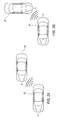
- FIG. 2A is a representational view of one warning to alert an operator of an impending blind spot event.
- FIG. 2B is a representational view of one warning alert to an operator of an impending rear crossing path event.
- FIG. 3 and 4 are schematic representation of a method according to the present invention.
- the apparatus or system 10 is comprised of at least two radar sensors 12, 14, one on each side of the vehicle, which may be positioned on a host vehicle 16, such that they are in the rear 18 and on sides 20 of the vehicle so that any blind spots are under surveillance. While one side of a vehicle is discussed, it is apparent to those skilled in the art that both sides of the vehicle are equipped with identical radar sensors and are equally covered. Automotive side view mirrors 15 and 17 on both sides of the vehicle and interior mounted rear view mirror 11 provide rear view information to the vehicle operators.
- rear view mirror 11 and side view mirrors 15 and 17 are electronically connected 13 to ECU 22 so that a warning alert for blind spot or rear crossing incidents can be signaled through the rear view mirror and side view mirrors as is better seen with reference to FIG. 2A and FIG 2B .
- this side blind spot zone 48 is a system defined region as shown for one side in Figure 2 .
- a rear crossing path zone 50 as described before is also shown for one side of the vehicle in Figure 2 .
- the combined blind spot detection and rear collision warning system is designed to operate in blind spot detection mode when the vehicle is traveling in the forward direction and it is designed to operate in rear crossing path warning mode when it is traveling in the reverse or backward direction as indicated by the engagement of vehicle reversing gear (not shown).
- the input from the radar sensors is transmitted to an electronic control module (ECU) 22 with memory 24.
- the ECU has a memory such as PROM, EPROM, EEPROM, Flash, or any other memory, and various tables are contained therein wherein maximum and minimum ranges are stored.
- the distances to the objects as determined by the radar sensors are compared against the various maximum distances for each radar beam for the blind spot detection zones and rear crossing path collision zones stored in the tables in the ECU depending upon whether the vehicle is traveling in the forward direction or traveling in the backward direction.
- the ECU continuously computes the distance to an object as perceived by the radar sensor(s) and compares that distance against the maximum range limit stored in the tables in the ECU for the blind spot detection or rear collision warning as needed. For example, if the vehicle is traveling in forward direction and an object is determined to be within the blind spot detection zone, the ECU sends a signal to an alarm 26 which is electronically connected at 25 to the ECU and an operator can be alerted.
- the rear crossing path warning application is further explained with reference to Figure 2 .
- Figure 2 is a schematic overview representation of a vehicle equipped with the combined blind spot detection and rear crossing path warning apparatus of the present invention traveling on a road showing the multiple beams and detection zones of each such beam for blind spot detection zone and rear crossing path collision warning zone.
- host vehicle 16 is shown with at least one radar sensor mounted on the rear and sides of the host vehicle.
- the sensors may be mounted in the vicinity of the B pillar or rearward of the B pillar of the host vehicle.
- Those skilled in the art recognize that whereas structures on one side of the vehicle are described, identical structures may be and preferably are mounted on the opposite side of the vehicle.
- Multiple overlapping radar beams 28, 30, 32, 34, 36, 38, 40 and 42 are shown, emanating from the rear and along the side of the host vehicle to detect oncoming vehicle 44 or 45 as it approaches from the rear in an adjacent lane 46 or from cross lane 47 respectively.
- programmable blind spot zone 48 forms a sub part of each multiple radar beam when the vehicle reverse gear is not engaged.
- the radar sensor zones further define a rear crossing path warning zone 50, to detect target vehicles approaching the host vehicle from a rear crossing path when the vehicle reverse gear is engaged.
- the radar sensor system detects the approaching object presence, its speed and trajectory, and the ECU uses the data signals to estimate a severity of collision and whether the object is an imminent threat.
- a warning signal is sent to the driver indicative of the threat.
- the warning may be audio or visual or haptic, or any combination thereof.
- the warning indicator may be visual signal in the rear view mirror and the side view mirrors.
- Other signals may be haptic signals in the steering wheel or seat or other area of the vehicle interior in contact with the driver, or it may be audio such as a voice or noise indication in the vehicle interior.
- the operation of the rear crossing path warning system mode may be explained in greater detail.
- the radar sensors detect an object, such as a target vehicle 45 encroaching into a crossing path zone 50.
- the target vehicle(s) may be detected as a possible warning event when it enters into a beam, and intrudes into the rear crossing path zone.
- the radar sensors transmit data signals to the ECU indicative of target vehicle approaching speed, trajectory, whether it is in the rear crossing path zone, and the ECU estimates the severity of any potential collision between the host vehicle and a target vehicle.
- the ECU further determines whether the target vehicle(s) is a threat event, and whether such a threat of collision is imminent.
- a warning signal is sent to the driver indicative of the threat.
- the object may also be approaching vehicles, or any other object that may pose a potential hazard to the host vehicle. After the threat has passed, the system deactivates the warning indicator.
- FIGS. 2A and 2B are a representation of images seen in the rear view mirror 11 and side view mirrors 15 and 17 of impending blind spot and rear crossing path incidents. While the discussion indicates these images or warning are seen in the rear view mirror and the side view mirrors, it is contemplated that these images may be warning alerts on the instrument panel of the vehicle. As seen in FIG. 2A , when a vehicle 46 intrudes into blind spot 48 as seen in FIG 2 , the image of 2A is seen as a warning alert in the rearview mirror and the side view mirrors or on the instrument panel of the host vehicle indicating that a blind spot event has or is occurring. Similarly, when vehicle 47 intrudes into rear crossing zone, the image of 2B may be displayed in the rear view mirror and side view mirrors or in the instrument panel as an alert warning an operator of an impending rear crossing path event.
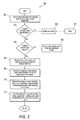
- Figure 3 and 4 show the steps of a method of combined blind spot detection and rear crossing path warning, in a host vehicle.
- method 58 begins with step 60 which is monitoring at least one vehicle blind spot and rear crossing path radar sensor diagnostics.
- step 62 is determining whether a host vehicle blind spot and rear crossing path warning radar sensors are within operational specification(s). If not, step 63 is to notify operator of the error, and step 61 is to stop the method.
- step 64 is determining whether a host vehicle is in reverse gear. If the determination is no, then step 65 is to operate the vehicle in the blind spot detection mode.
- Step 66 is determining the host vehicle state, reversing speed and host vehicle trajectory.
- Step 68 is determining if objects are present in crossing path detection zone on at least one side of the host vehicle.
- Step 70 is detecting at least one of distance, speed, direction, time in zone of at least one target in the rear crossing path zone.
- Step 72 is classifying objects detected in the rear crossing path zone as threatening or non-threatening objects.
- Step 74 is determining whether any threatening object is encroaching in the rear crossing path detection zone. If no, step 76 is return to step 60 to monitor radar sensors. If yes, step 78 is determining whether a collision threat exists and step 80 is estimating the severity of the collision threat.
- Step 82 is providing an appropriate warning to an operator of the host vehicle of any impending threat event.
- Step 82 may also include activation of automatic countermeasures such as brake application and sounding of the vehicle horn.
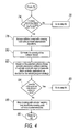
- the method may further include step 84, determining that the collision threat meets or exceeds a minimum threshold value. If yes, then step 85 is return to step 64. The vehicle is checked to ensure it is in reverse gear and the method follows the steps from 64 onward.
- step 84 if the collision threat is below the minimum threshold indicating that the threat event has passed, the warning signal and the automatic countermeasures are deactivated at step 86.
- step 88 the program control is transferred back to step 60 for sensor operational condition check.
Abstract
Description
- The present invention relates to a combined blind spot detection and rear crossing path collision detection and warning apparatus.
- In particular but not exclusively, the present invention relates to an apparatus and method for detecting possible objects in a driver's blind spot or rear crossing path using radar based sensors that are already in use on a vehicle for blind spot and lane change detection.
- In particular but not exclusively, the present invention relates to an apparatus and method for detecting possible collision objects in a driver's blind spot or rear crossing path using radar based sensors mounted rearward of the B pillar of a host vehicle that estimates speed, trajectory and threat level of target vehicles in the rear crossing path zone to provide warning to a driver of a possible rear or rear crossing path collision.
- Blind spot detection system radar sensors have programmable range capability that allows them to define a specific region of interest for detection of vehicles and other objects within the blind spot areas. Blind spot detection and rear crossing path systems with programmable range capability have set a fixed, programmable, maximum limit to avoid false detection of objects in the lane or road beyond the adjacent lanes, such as guardrails, vehicles in lanes beyond the adjacent lane to the host vehicle, etc. Software solutions are also available to detect and eliminate stationary objects such as guard rails to minimize false positives in the vehicle blind spot detection zones.
- There is a continuing desire to improve such systems in a cost effective manner. Multi-beam radar systems with programmable range capabilities, electronic or mechanically scanning radar sensors with programmable range capabilities offer opportunities for providing multiple safety functions and features with the same radar sensors.
- It is desirable to use the same radar sensors currently in use for blind spot detection and lane change systems and to develop methods of operating these radar that provide rear crossing path collision warnings in addition to blind spot detection. Moreover, there is a continuing desire to create such a system that includes determinations of approaching vehicle trajectory, vehicle speed, and threat level of a vehicle in the rear crossing path zones to provide warnings to a driver of a vehicle equipped with such a system.
- According to a first aspect of the present invention there is provided an apparatus in accordance with Claim 1. According to a second aspect of the present invention there is provided a method in accordance with Claim 5.
- In one embodiment, the present invention is directed to a combined blind spot detection and a rear crossing path collision warning system for host vehicles having an ECU with a memory. The system comprises a blind spot detection and a rear crossing path collision warning system equipped with radar sensors having multiple beam selection control and programmable range capability to allow said radar sensors to define a specific region of interest for detection of vehicle within a blind spot area or a crossing path collision zone. A rear crossing path warning zone is a system specified zone on either side of the vehicle located towards the rear of the vehicle in which a target vehicle traveling towards the host vehicle at a moderate speed, up to 40 to 45 kilometers per hour may present a collision threat to the host vehicle while it is traveling in a backward direction. Advantageously, the multiple beam selection control has a separate programmable maximum range limit for each beam and, preferably, each beam partially overlaps neighboring beams. The blind spot detection and rear collision warning radar sensors preferably have programmable range capabilities, and are mounted in the rear portion of the vehicle i.e. from the B pillar rearward. Data signals from the rearward radar sensors are used to determine speed, trajectory and threat level of approaching vehicles or detected objects in the rear crossing path zones and, if an appropriate threat level is determined, provide an appropriate warning to the driver or the system may initiate appropriate active counter measures.
- In another embodiment, the present invention relates to a method for continuously monitoring a blind spot detection and rear crossing path warning system, in a host vehicle. The method comprises monitoring at least one host vehicle blind spot and rear crossing path warning radar sensor diagnostics; determining whether said host vehicle blind spot and rear crossing path warning radar sensors are within operational specifications; determining whether said host vehicle is in reverse gear; determining said host vehicle state, reversing speed and vehicle trajectory; determining objects in rear crossing path detection zones on at least one side of said host vehicle; detecting at least one of distance, speed, direction, time in zone of at least one target object in said rear crossing path detection zone; classifying objects detected in said zone into threatening and non-threatening objects; determining whether any threatening objects are in said rear crossing path zone; determining a collision threat and estimating a severity of collision threat, and providing appropriate warning to an operator of said host vehicle of an impending threat event.
- The method may further include determining whether the collision threat exists above a minimum threshold value. If the vehicle is in reverse gear and the threat event is above a minimum threshold, the method may further initiate automatic countermeasures to mitigate rear crossing path collisions. Once the collision threat has passed, the method may include deactivating the rear crossing pass collision warning and automatic countermeasures. In the event it is determined that a vehicle is not in reverse gear, the vehicle may be operated in a blind spot detection mode.
- Finally, the method may include determining whether the radar sensors are functioning within specification. In the event it is determined that they are not, a fault may be logged in the ECU and a warning indicator can be activated, such as a light on an instrument panel, to alert the operator that the rearward radar sensors are in need of service.
-
FIG. 1 is a schematic representation of a block diagram of the apparatus of the present invention; -
FIG. 2 is a schematic overview representation of a vehicle equipped with the combined blind spot detection and rear crossing path collision warning apparatus of the present invention traveling rearward on a path showing the multiple beam radar system, crossing path zone and the blind spot zone on one side of said host vehicle (a similar system exists on the other side); -
FIG. 2A is a representational view of one warning to alert an operator of an impending blind spot event. -
FIG. 2B is a representational view of one warning alert to an operator of an impending rear crossing path event. -
FIG. 3 and4 are schematic representation of a method according to the present invention; - Turning now to the drawings wherein like numbers depict like structures, and particularly to
Figure 1 , the apparatus orsystem 10 is comprised of at least tworadar sensors host vehicle 16, such that they are in the rear 18 and on sides 20 of the vehicle so that any blind spots are under surveillance. While one side of a vehicle is discussed, it is apparent to those skilled in the art that both sides of the vehicle are equipped with identical radar sensors and are equally covered. Automotiveside view mirrors rear view mirror 11 provide rear view information to the vehicle operators. In addition,rear view mirror 11 andside view mirrors FIG. 2A and FIG 2B . It is possible to have blind spots in the adjacent lanes towards the rear of the host vehicle on either side of the vehicle if the side view mirrors are not properly adjusted. Typically this sideblind spot zone 48 is a system defined region as shown for one side inFigure 2 . A rearcrossing path zone 50 as described before is also shown for one side of the vehicle inFigure 2 . The combined blind spot detection and rear collision warning system is designed to operate in blind spot detection mode when the vehicle is traveling in the forward direction and it is designed to operate in rear crossing path warning mode when it is traveling in the reverse or backward direction as indicated by the engagement of vehicle reversing gear (not shown).The input from the radar sensors is transmitted to an electronic control module (ECU) 22 withmemory 24. The ECU has a memory such as PROM, EPROM, EEPROM, Flash, or any other memory, and various tables are contained therein wherein maximum and minimum ranges are stored. Specifically, as the radar sensor data are received, the distances to the objects as determined by the radar sensors are compared against the various maximum distances for each radar beam for the blind spot detection zones and rear crossing path collision zones stored in the tables in the ECU depending upon whether the vehicle is traveling in the forward direction or traveling in the backward direction. The ECU continuously computes the distance to an object as perceived by the radar sensor(s) and compares that distance against the maximum range limit stored in the tables in the ECU for the blind spot detection or rear collision warning as needed. For example, if the vehicle is traveling in forward direction and an object is determined to be within the blind spot detection zone, the ECU sends a signal to analarm 26 which is electronically connected at 25 to the ECU and an operator can be alerted. The rear crossing path warning application is further explained with reference toFigure 2 . -
Figure 2 is a schematic overview representation of a vehicle equipped with the combined blind spot detection and rear crossing path warning apparatus of the present invention traveling on a road showing the multiple beams and detection zones of each such beam for blind spot detection zone and rear crossing path collision warning zone. - Specifically,
host vehicle 16 is shown with at least one radar sensor mounted on the rear and sides of the host vehicle. By rear of the vehicle, it is understood that the sensors may be mounted in the vicinity of the B pillar or rearward of the B pillar of the host vehicle. Those skilled in the art recognize that whereas structures on one side of the vehicle are described, identical structures may be and preferably are mounted on the opposite side of the vehicle. Multiple overlappingradar beams oncoming vehicle adjacent lane 46 or fromcross lane 47 respectively. Within each radar beam, programmableblind spot zone 48 forms a sub part of each multiple radar beam when the vehicle reverse gear is not engaged. In addition, the radar sensor zones further define a rear crossingpath warning zone 50, to detect target vehicles approaching the host vehicle from a rear crossing path when the vehicle reverse gear is engaged. When an object or approaching vehicle is detected in the rear crossing path warning zone, and the host vehicle is engaged in reverse gear, the radar sensor system detects the approaching object presence, its speed and trajectory, and the ECU uses the data signals to estimate a severity of collision and whether the object is an imminent threat. In the event it is, a warning signal is sent to the driver indicative of the threat. The warning may be audio or visual or haptic, or any combination thereof. Preferably, the warning indicator may be visual signal in the rear view mirror and the side view mirrors. Other signals may be haptic signals in the steering wheel or seat or other area of the vehicle interior in contact with the driver, or it may be audio such as a voice or noise indication in the vehicle interior. - In one embodiment of the present invention, the operation of the rear crossing path warning system mode may be explained in greater detail. Specifically, as a host vehicle travels rearwardly as indicated by
arrow 56, the radar sensors detect an object, such as atarget vehicle 45 encroaching into acrossing path zone 50. The target vehicle(s) may be detected as a possible warning event when it enters into a beam, and intrudes into the rear crossing path zone. The radar sensors transmit data signals to the ECU indicative of target vehicle approaching speed, trajectory, whether it is in the rear crossing path zone, and the ECU estimates the severity of any potential collision between the host vehicle and a target vehicle. The ECU further determines whether the target vehicle(s) is a threat event, and whether such a threat of collision is imminent. If a determination is made that the threat event is imminent, a warning signal is sent to the driver indicative of the threat. Those skilled in the art understand that the object may also be approaching vehicles, or any other object that may pose a potential hazard to the host vehicle. After the threat has passed, the system deactivates the warning indicator. -
FIGS. 2A and 2B are a representation of images seen in therear view mirror 11 and side view mirrors 15 and 17 of impending blind spot and rear crossing path incidents. While the discussion indicates these images or warning are seen in the rear view mirror and the side view mirrors, it is contemplated that these images may be warning alerts on the instrument panel of the vehicle. As seen inFIG. 2A , when avehicle 46 intrudes intoblind spot 48 as seen inFIG 2 , the image of 2A is seen as a warning alert in the rearview mirror and the side view mirrors or on the instrument panel of the host vehicle indicating that a blind spot event has or is occurring. Similarly, whenvehicle 47 intrudes into rear crossing zone, the image of 2B may be displayed in the rear view mirror and side view mirrors or in the instrument panel as an alert warning an operator of an impending rear crossing path event. -
Figure 3 and4 show the steps of a method of combined blind spot detection and rear crossing path warning, in a host vehicle. This method may be carried out using software. Specifically,method 58 begins withstep 60 which is monitoring at least one vehicle blind spot and rear crossing path radar sensor diagnostics.Step 62 is determining whether a host vehicle blind spot and rear crossing path warning radar sensors are within operational specification(s). If not, step 63 is to notify operator of the error, and step 61 is to stop the method.Step 64 is determining whether a host vehicle is in reverse gear. If the determination is no, then step 65 is to operate the vehicle in the blind spot detection mode.Step 66 is determining the host vehicle state, reversing speed and host vehicle trajectory.Step 68 is determining if objects are present in crossing path detection zone on at least one side of the host vehicle.Step 70 is detecting at least one of distance, speed, direction, time in zone of at least one target in the rear crossing path zone.Step 72 is classifying objects detected in the rear crossing path zone as threatening or non-threatening objects.Step 74 is determining whether any threatening object is encroaching in the rear crossing path detection zone. If no, step 76 is return to step 60 to monitor radar sensors. If yes, step 78 is determining whether a collision threat exists and step 80 is estimating the severity of the collision threat.Step 82 is providing an appropriate warning to an operator of the host vehicle of any impending threat event.Step 82 may also include activation of automatic countermeasures such as brake application and sounding of the vehicle horn. The method may further includestep 84, determining that the collision threat meets or exceeds a minimum threshold value. If yes, then step 85 is return to step 64. The vehicle is checked to ensure it is in reverse gear and the method follows the steps from 64 onward. Instep 84, if the collision threat is below the minimum threshold indicating that the threat event has passed, the warning signal and the automatic countermeasures are deactivated atstep 86. Instep 88, the program control is transferred back to step 60 for sensor operational condition check. - While the invention has been described using particular words, those skilled in the art understand that the words utilized above are words of description and not words of limitation. Many variations and modifications are possible without departing from the scope of the invention as set forth in the appended claims.
Claims (15)
- A blind spot detection and rear crossing path warning apparatus (10) for a host vehicle (16), comprising:at least one radar sensor (12) mountable to a rear portion (18) of said host vehicle (16), wherein the or each radar sensor (12) is adapted to project at least one radar beam (28) and to transmit radar data to an electronic control unit (ECU) (22) with memory (24), and wherein the or each radar sensor (12) is capable of multiple data transmission to said ECU (22) and has an adjustable range limit for determining at least one of distance, speed and trajectory of an approaching object (42) to warn an operator when an object (42) is detected within said adjustable range limit;wherein said system is adapted to operate in a blind spot detection mode when said host vehicle (16) is in a forward gear and to operate in a rear crossing path warning mode when said host vehicle (16) is in reverse gear.
- The blind spot detection and rear crossing path warning apparatus (10) of claim 1, wherein said warning is at least one of an audio, visual, or haptic warning to said operator.
- The blind spot detection and rear crossing warning apparatus (10) of claim 1 or 2, wherein said rear portion (18) of said host vehicle (16) is from about said vehicle's B pillar rearward.
- The blind spot detection and rear crossing warning apparatus (10) of any previous claim, wherein a radar sensor (12) is mounted rearward of the B pillar on each side of said host vehicle (16).
- A method of providing blind spot detection and rear crossing path warning within a host vehicle (16) comprising:mounting at least one radar sensor (12) to a rear portion (18) of said host vehicle (16), the or each radar sensor (12) being adapted to project at least one radar beam (28), and being capable of multiple data transmission to an electronic control unit (ECU) (22) with memory (24), and having an adjustable range limit;transmitting radar data to the ECU (22);determining whether said host vehicle (16) is in reverse gear;in the event that said host vehicle (16) is in reverse gear, detecting objects in a rear crossing path detection zone (50) on at least one side of said host vehicle (16);in the event that said host vehicle (16) is not in reverse gear, detecting objects in a blind spot detection zone (48) on at least one side of said host vehicle (16); determining at least one of distance, speed and direction, of at least one target object in at least one of said rear crossing path detection and blind spot detection zones (48, 50); andproviding appropriate warning to an operator of said host vehicle (16) when an object is detected within said adjustable range limit.
- The method of claim 5, including the steps of:classifying objects detected in said zones (48, 50) into threatening and non-threatening objects; anddetermining a collision threat and estimating a severity of collision threat.
- The method of claim 5 or 6, including the steps of:monitoring at least one of said host vehicle blind spot detection and rear crossing path warning radar sensor diagnostics; anddetermining whether said host vehicle blind spot detection or rear crossing path warning radar sensors (12) are within operational specifications.
- The method of claim 6, further including initiating automatic countermeasures to mitigate potential collision threat.
- The method of claim 8, wherein the automatic countermeasures include the application of vehicle brakes or sounding of the vehicle horn.
- The method of claim 6 or 8, further including determining whether the collision threat exists above a minimum threshold value.
- The method of claim 10 when dependent on claim 8 wherein when said collision event does not exist above a minimum threshold value, the rear crossing path collision warning and associated automatic countermeasures are deactivated.
- The method of claim 7, wherein if the radar sensors (12) are not operating within specification, a notification of the error is sent to the operator.
- The method of any of claims 6 to 12, wherein the warning is visual, audio or haptic.
- The method of any of claims 6 to 13, wherein a crossing path visual warning is displayed at or near at least one of the side view mirrors (15).
- The method of any of claims 6 to 13, wherein a crossing path visual warning is displayed at or near the interior rearview mirror (11).
Applications Claiming Priority (1)
| Application Number | Priority Date | Filing Date | Title |
|---|---|---|---|
| US11/839,903 US8552848B2 (en) | 2007-08-16 | 2007-08-16 | System and method for combined blind spot detection and rear crossing path collision warning |
Publications (1)
| Publication Number | Publication Date |
|---|---|
| EP2026099A1 true EP2026099A1 (en) | 2009-02-18 |
Family
ID=39870343
Family Applications (1)
| Application Number | Title | Priority Date | Filing Date |
|---|---|---|---|
| EP08159780A Ceased EP2026099A1 (en) | 2007-08-16 | 2008-07-04 | System and method for combined blind spot detection and rear crossing path collision warning |
Country Status (3)
| Country | Link |
|---|---|
| US (1) | US8552848B2 (en) |
| EP (1) | EP2026099A1 (en) |
| CN (1) | CN101369020A (en) |
Cited By (18)
| Publication number | Priority date | Publication date | Assignee | Title |
|---|---|---|---|---|
| WO2011131477A1 (en) * | 2010-04-23 | 2011-10-27 | Valeo Schalter Und Sensoren Gmbh | Method for warning a driver of a vehicle of the presence of objects in a blind spot region and corresponding driver assistance system |
| WO2012021668A1 (en) * | 2010-08-12 | 2012-02-16 | Robert Bosch Gmbh | System and method for detecting a potential threat to a vehicle and generating a warning to a driver |
| WO2012089384A1 (en) * | 2010-12-29 | 2012-07-05 | Robert Bosch Gmbh | Radar sensor for motor vehicles |
| EP2487505A1 (en) * | 2011-02-10 | 2012-08-15 | Harman Becker Automotive Systems GmbH | Blind area warning for vehicles |
| GB2498639A (en) * | 2012-01-16 | 2013-07-24 | Ford Global Tech Llc | A system and method for detecting objects approaching a vehicle |
| US8525655B2 (en) | 2008-07-30 | 2013-09-03 | Nissan Motor Co., Ltd. | Vehicle control system |
| WO2013135294A1 (en) * | 2012-03-15 | 2013-09-19 | Toyota Motor Europe Nv/Sa | Headlight system and control method |
| DE102012208998A1 (en) | 2012-05-29 | 2013-12-05 | Bayerische Motoren Werke Aktiengesellschaft | Method for preventing collision of backward or forward moving motor car with crossing vehicle in e.g. transverse parking lot, involves performing automatic reset of motor car at preset direction, if collision hazard is detected |
| WO2014048530A1 (en) * | 2012-09-29 | 2014-04-03 | Daimler Ag | Method and device for operating a vehicle and vehicle having such a device |
| EP2815929A4 (en) * | 2012-02-17 | 2015-07-08 | Nissan Motor | Travel control device and travel control method |
| WO2015193038A3 (en) * | 2014-06-17 | 2016-02-11 | Volkswagen Aktiengesellschaft | Determining a state of a vehicle and assisting a driver in driving the vehicle |
| CN106114479A (en) * | 2016-03-06 | 2016-11-16 | 李春 | Based on the AMRS that GPRS and micropower are wireless |
| CN109263550A (en) * | 2018-08-27 | 2019-01-25 | 合肥移顺信息技术有限公司 | Vehicle blind zone monitor and alarm system |
| CN110395179A (en) * | 2018-04-24 | 2019-11-01 | 宝沃汽车(中国)有限公司 | Blind area overtake other vehicles monitoring device, determine the method, apparatus and vehicle of driving intention |
| CN110667591A (en) * | 2018-07-02 | 2020-01-10 | 百度(美国)有限责任公司 | Planned driving perception system for autonomous vehicles |
| US20220063671A1 (en) * | 2020-08-31 | 2022-03-03 | Ford Global Technologies, Llc | Vehicle operation along planned path |
| EP2729828B1 (en) * | 2011-07-05 | 2022-10-05 | Robert Bosch GmbH | Radar system for motor vehicles, and motor vehicle having a radar system |
| EP4177637A1 (en) * | 2021-11-05 | 2023-05-10 | Continental Autonomous Mobility Germany GmbH | Method for classifying target objects, classification device, and driver assistance system |
Families Citing this family (264)
| Publication number | Priority date | Publication date | Assignee | Title |
|---|---|---|---|---|
| US8645001B2 (en) * | 2007-09-04 | 2014-02-04 | International Business Machines Corporation | Method and system for blind spot identification and warning utilizing visual indicators |
| TWI314115B (en) * | 2007-09-27 | 2009-09-01 | Ind Tech Res Inst | Method and apparatus for predicting/alarming the moving of hidden objects |
| US8280621B2 (en) * | 2008-04-15 | 2012-10-02 | Caterpillar Inc. | Vehicle collision avoidance system |
| US8219281B2 (en) * | 2008-12-05 | 2012-07-10 | International Business Machines Corporation | Controlling vehicle operations based on object presence |
| US7978096B2 (en) * | 2009-04-28 | 2011-07-12 | Ford Global Technologies, Llc | Parking angle determination and cross traffic alert |
| US8072352B2 (en) * | 2009-04-28 | 2011-12-06 | Ford Global Technologies, Llc | Cross traffic alert with parking angle trajectory |
| SE534621C2 (en) * | 2010-01-19 | 2011-10-25 | Volvo Technology Corp | Device for dead angle warning |
| DE102010011497A1 (en) * | 2010-03-16 | 2011-09-22 | GM Global Technology Operations LLC , (n. d. Ges. d. Staates Delaware) | Method for avoiding or mitigating a collision, control device for a driver assistance system and vehicle |
| US9639688B2 (en) | 2010-05-27 | 2017-05-02 | Ford Global Technologies, Llc | Methods and systems for implementing and enforcing security and resource policies for a vehicle |
| DE102010040692A1 (en) * | 2010-09-14 | 2012-03-15 | Robert Bosch Gmbh | Radar sensor for motor vehicles, in particular LCA sensor |
| CN101987596B (en) * | 2010-11-04 | 2012-11-28 | 奇瑞汽车股份有限公司 | Control method of parking assisting system |
| US9452735B2 (en) | 2011-02-10 | 2016-09-27 | Ford Global Technologies, Llc | System and method for controlling a restricted mode in a vehicle |
| US8522320B2 (en) | 2011-04-01 | 2013-08-27 | Ford Global Technologies, Llc | Methods and systems for authenticating one or more users of a vehicle communications and information system |
| US20120268260A1 (en) * | 2011-04-21 | 2012-10-25 | Ford Global Technologies, Llc | Method and apparatus for dynamically providing space management alerts for a vehicle |
| CN102323972B (en) * | 2011-05-31 | 2013-09-25 | 电子科技大学 | Method for managing phased array radar resource |
| US8788113B2 (en) | 2011-06-13 | 2014-07-22 | Ford Global Technologies, Llc | Vehicle driver advisory system and method |
| US8849519B2 (en) | 2011-08-09 | 2014-09-30 | Ford Global Technologies, Llc | Method and apparatus for vehicle hardware theft prevention |
| US9415774B2 (en) * | 2011-09-22 | 2016-08-16 | Nissan Motor Co., Ltd. | Vehicle control apparatus including an obstacle detection device |
| US9050930B2 (en) * | 2011-10-14 | 2015-06-09 | Xerox Corporation | Collision avoidance signal |
| US9586525B2 (en) | 2011-11-28 | 2017-03-07 | Robert Bosch Gmbh | Camera-assisted blind spot detection |
| US9041552B2 (en) * | 2012-01-10 | 2015-05-26 | Xiao Lin Yu | Automobile blind spot detection system and method |
| US20140354450A1 (en) * | 2012-02-10 | 2014-12-04 | Yoshihiko Takahashi | Warning device |
| US9569403B2 (en) | 2012-05-03 | 2017-02-14 | Ford Global Technologies, Llc | Methods and systems for authenticating one or more users of a vehicle communications and information system |
| US20140184399A1 (en) * | 2012-12-31 | 2014-07-03 | Kia Motors Corporation | Rear collision warning alert system and method |
| US9688246B2 (en) | 2013-02-25 | 2017-06-27 | Ford Global Technologies, Llc | Method and apparatus for in-vehicle alarm activation and response handling |
| US8947221B2 (en) | 2013-02-26 | 2015-02-03 | Ford Global Technologies, Llc | Method and apparatus for tracking device connection and state change |
| US9141583B2 (en) | 2013-03-13 | 2015-09-22 | Ford Global Technologies, Llc | Method and system for supervising information communication based on occupant and vehicle environment |
| US9002536B2 (en) | 2013-03-14 | 2015-04-07 | Ford Global Technologies, Llc | Key fob security copy to a mobile phone |
| JP2016536703A (en) * | 2013-09-05 | 2016-11-24 | ローベルト ボッシュ ゲゼルシャフト ミット ベシュレンクテル ハフツング | Altitude lane departure warning based on data from rear radar sensor |
| KR101815721B1 (en) * | 2013-10-07 | 2018-01-08 | 주식회사 만도 | Apparatuses and Methods for warning blind spot |
| US9463739B2 (en) | 2013-11-21 | 2016-10-11 | Ford Global Technologies, Llc | Sun visor with photoluminescent structure |
| US9481297B2 (en) | 2013-11-21 | 2016-11-01 | Ford Global Technologies, Llc | Illuminated steering assembly |
| US9613549B2 (en) | 2013-11-21 | 2017-04-04 | Ford Global Technologies, Llc | Illuminating badge for a vehicle |
| US9839098B2 (en) | 2013-11-21 | 2017-12-05 | Ford Global Technologies, Llc | Light assembly operable as a dome lamp |
| US9463736B2 (en) | 2013-11-21 | 2016-10-11 | Ford Global Technologies, Llc | Illuminated steering assembly |
| US9499096B2 (en) | 2013-11-21 | 2016-11-22 | Ford Global Technologies, Llc | Photoluminescent vehicle reading lamp |
| US9487126B2 (en) | 2013-11-21 | 2016-11-08 | Ford Global Technologies, Llc | Photoluminescent puddle lamp |
| US9538874B2 (en) | 2013-11-21 | 2017-01-10 | Ford Global Technologies, Llc | Photoluminescent cupholder illumination |
| US9789810B2 (en) | 2013-11-21 | 2017-10-17 | Ford Global Technologies, Llc | Photoluminescent vehicle panel |
| US9539939B2 (en) | 2013-11-21 | 2017-01-10 | Ford Global Technologies, Llc | Photoluminescent logo for vehicle trim and fabric |
| US9598632B2 (en) | 2013-11-21 | 2017-03-21 | Ford Global Technologies, Llc | Method for depositing photoluminescent material |
| US9771019B2 (en) | 2013-11-21 | 2017-09-26 | Ford Global Technologies, Inc. | Photoluminescent vehicle illumination |
| US9464776B2 (en) | 2013-11-21 | 2016-10-11 | Ford Global Technologies, Llc | Vehicle light system with illuminating exhaust |
| US9849831B2 (en) | 2013-11-21 | 2017-12-26 | Ford Global Technologies, Llc | Printed LED storage compartment |
| US10064256B2 (en) | 2013-11-21 | 2018-08-28 | Ford Global Technologies, Llc | System and method for remote activation of vehicle lighting |
| US9492575B2 (en) | 2013-11-21 | 2016-11-15 | Ford Global Technologies, Llc | Color changing and disinfecting surfaces |
| US9688192B2 (en) | 2013-11-21 | 2017-06-27 | Ford Global Technologies, Llc | Vehicle having interior and exterior lighting on tailgate |
| US9688186B2 (en) | 2013-11-21 | 2017-06-27 | Ford Global Technologies, Llc | Illuminating decal for a vehicle |
| US9586518B2 (en) | 2013-11-21 | 2017-03-07 | Ford Global Technologies, Llc | Luminescent grille bar assembly |
| US9796304B2 (en) | 2013-11-21 | 2017-10-24 | Ford Global Technologies, Llc | Vehicle floor lighting system having a pivotable base with light-producing assembly coupled to base |
| US9573517B2 (en) | 2013-11-21 | 2017-02-21 | Ford Global Technologies, Llc | Door illumination and warning system |
| US9586523B2 (en) | 2013-11-21 | 2017-03-07 | Ford Global Technologies, Llc | Vehicle lighting assembly |
| US9539941B2 (en) | 2013-11-21 | 2017-01-10 | Ford Global Technologies, Llc | Photoluminescent cupholder illumination |
| US9463737B2 (en) | 2013-11-21 | 2016-10-11 | Ford Global Technologies, Llc | Illuminated seatbelt assembly |
| US9495040B2 (en) | 2013-11-21 | 2016-11-15 | Ford Global Technologies, Llc | Selectively visible user interface |
| US9464886B2 (en) | 2013-11-21 | 2016-10-11 | Ford Global Technologies, Llc | Luminescent hitch angle detection component |
| US10400978B2 (en) | 2013-11-21 | 2019-09-03 | Ford Global Technologies, Llc | Photoluminescent lighting apparatus for vehicles |
| US9821708B2 (en) | 2013-11-21 | 2017-11-21 | Ford Global Technologies, Llc | Illuminated exterior strip |
| US9539940B2 (en) | 2013-11-21 | 2017-01-10 | Ford Global Technologies, Llc | Illuminated indicator |
| US9797575B2 (en) | 2013-11-21 | 2017-10-24 | Ford Global Technologies, Llc | Light-producing assembly for a vehicle |
| US9810401B2 (en) | 2013-11-21 | 2017-11-07 | Ford Global Technologies, Llc | Luminescent trim light assembly |
| US9905743B2 (en) | 2013-11-21 | 2018-02-27 | Ford Global Technologies, Llc | Printed LED heat sink double lock |
| US9457712B2 (en) | 2013-11-21 | 2016-10-04 | Ford Global Technologies, Llc | Vehicle sun visor providing luminescent lighting |
| US9440579B2 (en) | 2013-11-21 | 2016-09-13 | Ford Global Technologies, Llc | Photoluminescent step handle |
| US9682651B2 (en) | 2013-11-21 | 2017-06-20 | Ford Global Technologies, Llc | Vehicle lighting system with improved substrate |
| US9868387B2 (en) | 2013-11-21 | 2018-01-16 | Ford Global Technologies, Llc | Photoluminescent printed LED molding |
| US9464803B2 (en) | 2013-11-21 | 2016-10-11 | Ford Global Technologies, Llc | Illuminated speaker |
| US9499113B2 (en) | 2013-11-21 | 2016-11-22 | Ford Global Technologies, Llc | Luminescent grille bar assembly |
| US9587800B2 (en) | 2013-11-21 | 2017-03-07 | Ford Global Technologies, Llc | Luminescent vehicle molding |
| US10041650B2 (en) | 2013-11-21 | 2018-08-07 | Ford Global Technologies, Llc | Illuminated instrument panel storage compartment |
| US9487136B2 (en) | 2013-11-21 | 2016-11-08 | Ford Global Technologies, Llc | System and method to locate vehicle equipment |
| US9989216B2 (en) | 2013-11-21 | 2018-06-05 | Ford Global Technologies, Llc | Interior exterior moving designs |
| US9487135B2 (en) | 2013-11-21 | 2016-11-08 | Ford Global Technologies, Llc | Dome light assembly |
| US9527438B2 (en) | 2013-11-21 | 2016-12-27 | Ford Global Technologies, Llc | Photoluminescent blind spot warning indicator |
| US9469244B2 (en) | 2013-11-21 | 2016-10-18 | Ford Global Technologies, Llc | Luminescent vehicle seal |
| US9487127B2 (en) | 2013-11-21 | 2016-11-08 | Ford Global Technologies, Llc | Photoluminescent vehicle step lamp |
| US9782504B2 (en) | 2013-11-21 | 2017-10-10 | Ford Global Technologies, Inc. | Self-disinfecting surface with printed LEDs for a surface of a vehicle |
| US9764686B2 (en) | 2013-11-21 | 2017-09-19 | Ford Global Technologies, Llc | Light-producing assembly for a vehicle |
| US9487128B2 (en) | 2013-11-21 | 2016-11-08 | Ford Global Technologies, Llc | Illuminating running board |
| US9969323B2 (en) | 2013-11-21 | 2018-05-15 | Ford Global Technologies, Llc | Vehicle lighting system employing a light strip |
| US9694743B2 (en) | 2013-11-21 | 2017-07-04 | Ford Global Technologies, Llc | Dual purpose lighting assembly |
| US9499090B2 (en) | 2013-11-21 | 2016-11-22 | Ford Global Technologies, Llc | Spoiler using photoluminescent illumination |
| US9573516B2 (en) | 2013-11-21 | 2017-02-21 | Ford Global Technologies, Llc | Rear vehicle lighting system |
| US9499092B2 (en) | 2013-11-21 | 2016-11-22 | Ford Global Technologies, Llc | Illuminating molding for a vehicle |
| US9649877B2 (en) | 2013-11-21 | 2017-05-16 | Ford Global Technologies, Llc | Vehicle light system with illuminating wheel assembly |
| US9625115B2 (en) | 2013-11-21 | 2017-04-18 | Ford Global Technologies, Llc | Photoluminescent vehicle graphics |
| US9682649B2 (en) | 2013-11-21 | 2017-06-20 | Ford Global Technologies, Inc. | Photoluminescent winch apparatus |
| US9796325B2 (en) | 2013-11-21 | 2017-10-24 | Ford Global Technologies, Llc | Exterior light system for a vehicle |
| US9493113B2 (en) | 2013-11-21 | 2016-11-15 | Ford Global Technologies, Llc | Photoluminescent cargo area illumination |
| US9809160B2 (en) | 2013-11-21 | 2017-11-07 | Ford Global Technologies, Llc | Tailgate illumination system |
| US9961745B2 (en) | 2013-11-21 | 2018-05-01 | Ford Global Technologies, Llc | Printed LED rylene dye welcome/farewell lighting |
| US9950658B2 (en) | 2013-11-21 | 2018-04-24 | Ford Global Technologies, Llc | Privacy window system |
| US9464887B2 (en) | 2013-11-21 | 2016-10-11 | Ford Global Technologies, Llc | Illuminated hitch angle detection component |
| US9533613B2 (en) | 2013-11-21 | 2017-01-03 | Ford Global Technologies, Llc | Photoluminescent fuel filler door |
| US9583968B2 (en) | 2013-11-21 | 2017-02-28 | Ford Global Technologies, Llc | Photoluminescent disinfecting and charging bin |
| US9902320B2 (en) | 2013-11-21 | 2018-02-27 | Ford Global Technologies, Llc | Photoluminescent color changing dome map lamp |
| US9463738B2 (en) | 2013-11-21 | 2016-10-11 | Ford Global Technologies, Llc | Seatbelt lighting system |
| US9931991B2 (en) | 2013-11-21 | 2018-04-03 | Ford Global Technologies, Llc | Rotating garment hook |
| US10363867B2 (en) | 2013-11-21 | 2019-07-30 | Ford Global Technologies, Llc | Printed LED trim panel lamp |
| US9463734B2 (en) | 2013-11-21 | 2016-10-11 | Ford Global Technologies, Llc | Illuminated seatbelt assembly |
| KR102186350B1 (en) * | 2014-05-30 | 2020-12-03 | 현대모비스 주식회사 | Apparatus and method for requesting emergency call about vehicle accident using driving information of vehicle |
| DE102015109378A1 (en) | 2014-07-02 | 2016-01-07 | Ford Global Technologies, Llc | Photoluminescent blind spot warning display |
| JP6115529B2 (en) * | 2014-08-01 | 2017-04-19 | マツダ株式会社 | Vehicle driving support device and driving support method |
| US9493117B2 (en) * | 2014-10-08 | 2016-11-15 | Ford Global Technologies, Llc | Vehicle blind spot system operation with trailer tow |
| KR102239014B1 (en) * | 2014-11-10 | 2021-04-13 | 현대모비스 주식회사 | System and method for alarm controlling of dead angle zone |
| US10249123B2 (en) | 2015-04-09 | 2019-04-02 | Ford Global Technologies, Llc | Systems and methods for mobile phone key fob management |
| JP6292184B2 (en) * | 2015-07-06 | 2018-03-14 | トヨタ自動車株式会社 | Collision avoidance device |
| US10168039B2 (en) | 2015-08-10 | 2019-01-01 | Ford Global Technologies, Llc | Illuminated badge for a vehicle |
| US9663967B2 (en) | 2015-09-11 | 2017-05-30 | Ford Global Technologies, Llc | Illuminated latch system |
| US9463735B1 (en) | 2015-10-06 | 2016-10-11 | Ford Global Technologies, Llc | Vehicle visor assembly with illuminating check assembly |
| US10576889B2 (en) | 2015-10-18 | 2020-03-03 | Danielle Constantine | Wireless sensor or device, portable or detachable from either a motorized or unmotorized vehicle, connected via a phone or electronic tablet application system |
| US20170124881A1 (en) * | 2015-10-28 | 2017-05-04 | Velvac Incorporated | Blind zone warning for semi-trailer |
| US9620019B1 (en) * | 2015-11-03 | 2017-04-11 | Denso International America, Inc. | Methods and systems for facilitating vehicle lane change |
| US9694739B2 (en) | 2015-11-10 | 2017-07-04 | Ford Global Technologies, Llc | Disinfecting handle |
| US9889791B2 (en) | 2015-12-01 | 2018-02-13 | Ford Global Technologies, Llc | Illuminated badge for a vehicle |
| US10023100B2 (en) | 2015-12-14 | 2018-07-17 | Ford Global Technologies, Llc | Illuminated trim assembly |
| US9500333B1 (en) | 2015-12-18 | 2016-11-22 | Ford Global Technologies, Llc | Phosphorescent lighting assembly |
| WO2017113078A1 (en) * | 2015-12-29 | 2017-07-06 | 华为技术有限公司 | Switching method and portable electronic device |
| US20170192091A1 (en) * | 2016-01-06 | 2017-07-06 | Ford Global Technologies, Llc | System and method for augmented reality reduced visibility navigation |
| US10235911B2 (en) | 2016-01-12 | 2019-03-19 | Ford Global Technologies, Llc | Illuminating badge for a vehicle |
| US9855799B2 (en) | 2016-02-09 | 2018-01-02 | Ford Global Technologies, Llc | Fuel level indicator |
| US10501007B2 (en) | 2016-01-12 | 2019-12-10 | Ford Global Technologies, Llc | Fuel port illumination device |
| US10300843B2 (en) | 2016-01-12 | 2019-05-28 | Ford Global Technologies, Llc | Vehicle illumination assembly |
| US10011219B2 (en) | 2016-01-18 | 2018-07-03 | Ford Global Technologies, Llc | Illuminated badge |
| US9927114B2 (en) | 2016-01-21 | 2018-03-27 | Ford Global Technologies, Llc | Illumination apparatus utilizing conductive polymers |
| US9517723B1 (en) | 2016-01-21 | 2016-12-13 | Ford Global Technologies, Llc | Illuminated tie-down cleat |
| US9586519B1 (en) | 2016-01-27 | 2017-03-07 | Ford Global Technologies, Llc | Vehicle rear illumination |
| US10328949B2 (en) * | 2016-01-28 | 2019-06-25 | Toyota Motor Engineering & Manufacturing North America, Inc. | Sensor blind spot indication for vehicles |
| US9623797B1 (en) | 2016-02-04 | 2017-04-18 | Ford Global Technologies, Llc | Lift gate lamp |
| US9964642B2 (en) | 2016-02-04 | 2018-05-08 | Toyota Motor Engineering & Manufacturing North America, Inc. | Vehicle with system for detecting arrival at cross road and automatically displaying side-front camera image |
| US9499093B1 (en) | 2016-02-08 | 2016-11-22 | Ford Global Technologies, Llc | Retractable running board with long-persistance phosphor lighting |
| US9499094B1 (en) | 2016-02-08 | 2016-11-22 | Ford Global Technologies, Llc | Retractable running board with long-persistence phosphor lighting |
| US10189401B2 (en) | 2016-02-09 | 2019-01-29 | Ford Global Technologies, Llc | Vehicle light strip with optical element |
| US9664354B1 (en) | 2016-02-11 | 2017-05-30 | Ford Global Technologies, Llc | Illumination assembly |
| US9656598B1 (en) | 2016-02-23 | 2017-05-23 | Ford Global Technologies, Llc | Vehicle badge |
| US9751458B1 (en) | 2016-02-26 | 2017-09-05 | Ford Global Technologies, Llc | Vehicle illumination system |
| US10501025B2 (en) | 2016-03-04 | 2019-12-10 | Ford Global Technologies, Llc | Vehicle badge |
| US9688189B1 (en) | 2016-03-09 | 2017-06-27 | Ford Global Technologies, Llc | Illuminated license plate |
| US10118568B2 (en) | 2016-03-09 | 2018-11-06 | Ford Global Technologies, Llc | Vehicle badge having discretely illuminated portions |
| US9688190B1 (en) | 2016-03-15 | 2017-06-27 | Ford Global Technologies, Llc | License plate illumination system |
| US9963001B2 (en) | 2016-03-24 | 2018-05-08 | Ford Global Technologies, Llc | Vehicle wheel illumination assembly using photoluminescent material |
| US10081296B2 (en) | 2016-04-06 | 2018-09-25 | Ford Global Technologies, Llc | Illuminated exterior strip with photoluminescent structure and retroreflective layer |
| US9947226B2 (en) | 2016-04-12 | 2018-04-17 | Denso International America, Inc. | Methods and systems for blind spot monitoring with dynamic detection range |
| US9931981B2 (en) * | 2016-04-12 | 2018-04-03 | Denso International America, Inc. | Methods and systems for blind spot monitoring with rotatable blind spot sensor |
| US9975480B2 (en) | 2016-04-12 | 2018-05-22 | Denso International America, Inc. | Methods and systems for blind spot monitoring with adaptive alert zone |
| US9994151B2 (en) | 2016-04-12 | 2018-06-12 | Denso International America, Inc. | Methods and systems for blind spot monitoring with adaptive alert zone |
| US9902315B2 (en) | 2016-04-15 | 2018-02-27 | Ford Global Technologies, Llc | Photoluminescent lighting apparatus for vehicles |
| US9758088B1 (en) | 2016-05-10 | 2017-09-12 | Ford Global Technologies, Llc | Auxiliary lighting roof rack |
| US9714749B1 (en) | 2016-05-10 | 2017-07-25 | Ford Global Technologies, Llc | Illuminated vehicle grille assembly |
| US10420189B2 (en) | 2016-05-11 | 2019-09-17 | Ford Global Technologies, Llc | Vehicle lighting assembly |
| US9688215B1 (en) | 2016-05-11 | 2017-06-27 | Ford Global Technologies, Llc | Iridescent vehicle applique |
| US9738219B1 (en) | 2016-05-11 | 2017-08-22 | Ford Global Technologies, Llc | Illuminated vehicle trim |
| US10064259B2 (en) | 2016-05-11 | 2018-08-28 | Ford Global Technologies, Llc | Illuminated vehicle badge |
| US9821710B1 (en) | 2016-05-12 | 2017-11-21 | Ford Global Technologies, Llc | Lighting apparatus for vehicle decklid |
| US10631373B2 (en) | 2016-05-12 | 2020-04-21 | Ford Global Technologies, Llc | Heated windshield indicator |
| US9994144B2 (en) | 2016-05-23 | 2018-06-12 | Ford Global Technologies, Llc | Illuminated automotive glazings |
| US9896020B2 (en) | 2016-05-23 | 2018-02-20 | Ford Global Technologies, Llc | Vehicle lighting assembly |
| US9925920B2 (en) * | 2016-05-24 | 2018-03-27 | Ford Global Technologies, Llc | Extended lane blind spot detection |
| US9925917B2 (en) | 2016-05-26 | 2018-03-27 | Ford Global Technologies, Llc | Concealed lighting for vehicles |
| US9937855B2 (en) | 2016-06-02 | 2018-04-10 | Ford Global Technologies, Llc | Automotive window glazings |
| US9803822B1 (en) | 2016-06-03 | 2017-10-31 | Ford Global Technologies, Llc | Vehicle illumination assembly |
| US10343622B2 (en) | 2016-06-09 | 2019-07-09 | Ford Global Technologies, Llc | Interior and exterior iridescent vehicle appliques |
| US10205338B2 (en) | 2016-06-13 | 2019-02-12 | Ford Global Technologies, Llc | Illuminated vehicle charging assembly |
| US9604567B1 (en) | 2016-06-15 | 2017-03-28 | Ford Global Technologies, Llc | Luminescent trailer hitch plug |
| US10131237B2 (en) | 2016-06-22 | 2018-11-20 | Ford Global Technologies, Llc | Illuminated vehicle charging system |
| CN106004655B (en) * | 2016-06-24 | 2019-04-19 | 深圳市元征科技股份有限公司 | A kind of blind spot anti-collision warning method and device |
| US9855888B1 (en) | 2016-06-29 | 2018-01-02 | Ford Global Technologies, Llc | Photoluminescent vehicle appliques |
| US10150414B2 (en) * | 2016-07-08 | 2018-12-11 | Ford Global Technologies, Llc | Pedestrian detection when a vehicle is reversing |
| US9840191B1 (en) | 2016-07-12 | 2017-12-12 | Ford Global Technologies, Llc | Vehicle lamp assembly |
| US9855797B1 (en) | 2016-07-13 | 2018-01-02 | Ford Global Technologies, Llc | Illuminated system for a vehicle |
| US9889801B2 (en) | 2016-07-14 | 2018-02-13 | Ford Global Technologies, Llc | Vehicle lighting assembly |
| US9573518B1 (en) | 2016-07-15 | 2017-02-21 | Ford Global Technologies, Llc | Floor console IR bin light |
| US9840193B1 (en) | 2016-07-15 | 2017-12-12 | Ford Global Technologies, Llc | Vehicle lighting assembly |
| US9604569B1 (en) | 2016-07-19 | 2017-03-28 | Ford Global Technologies, Llc | Window lighting system of a vehicle |
| US9587967B1 (en) | 2016-08-04 | 2017-03-07 | Ford Global Technologies, Llc | Vehicle container illumination |
| US9845047B1 (en) | 2016-08-08 | 2017-12-19 | Ford Global Technologies, Llc | Light system |
| US9573519B1 (en) | 2016-08-08 | 2017-02-21 | Ford Global Technologies, Llc | Engine compartment lighting to moving parts |
| US9573520B1 (en) | 2016-08-09 | 2017-02-21 | Ford Global Technologies, Llc | Luminescent console storage bin |
| US9827903B1 (en) | 2016-08-18 | 2017-11-28 | Ford Global Technologies, Llc | Illuminated trim panel |
| US9616823B1 (en) | 2016-08-22 | 2017-04-11 | Ford Global Technologies, Llc | Illuminated badge for a vehicle |
| US10173604B2 (en) | 2016-08-24 | 2019-01-08 | Ford Global Technologies, Llc | Illuminated vehicle console |
| US11423783B2 (en) | 2016-08-30 | 2022-08-23 | Hyundai Motor Company | Apparatus and method for implementing LCDAS |
| KR102033884B1 (en) * | 2016-12-30 | 2019-10-18 | 현대자동차주식회사 | An apparatus and method for implementing LCDAS |
| US10047911B2 (en) | 2016-08-31 | 2018-08-14 | Ford Global Technologies, Llc | Photoluminescent emission system |
| US9889798B1 (en) * | 2016-08-31 | 2018-02-13 | Autoliv Asp, Inc. | Detection of a target object utilizing automotive radar |
| US10047659B2 (en) | 2016-08-31 | 2018-08-14 | Ford Global Technologies, Llc | Photoluminescent engine indicium |
| US9604568B1 (en) | 2016-09-01 | 2017-03-28 | Ford Global Technologies, Llc | Vehicle light system |
| US10075013B2 (en) | 2016-09-08 | 2018-09-11 | Ford Global Technologies, Llc | Vehicle apparatus for charging photoluminescent utilities |
| US10308175B2 (en) | 2016-09-08 | 2019-06-04 | Ford Global Technologies, Llc | Illumination apparatus for vehicle accessory |
| US10065555B2 (en) | 2016-09-08 | 2018-09-04 | Ford Global Technologies, Llc | Directional approach lighting |
| US10043396B2 (en) | 2016-09-13 | 2018-08-07 | Ford Global Technologies, Llc | Passenger pickup system and method using autonomous shuttle vehicle |
| US9863171B1 (en) | 2016-09-28 | 2018-01-09 | Ford Global Technologies, Llc | Vehicle compartment |
| US9593820B1 (en) | 2016-09-28 | 2017-03-14 | Ford Global Technologies, Llc | Vehicle illumination system |
| US10046688B2 (en) | 2016-10-06 | 2018-08-14 | Ford Global Technologies, Llc | Vehicle containing sales bins |
| US10137829B2 (en) | 2016-10-06 | 2018-11-27 | Ford Global Technologies, Llc | Smart drop off lighting system |
| US9707887B1 (en) | 2016-10-19 | 2017-07-18 | Ford Global Technologies, Llc | Vehicle mirror assembly |
| US9914390B1 (en) | 2016-10-19 | 2018-03-13 | Ford Global Technologies, Llc | Vehicle shade assembly |
| US10086700B2 (en) | 2016-10-20 | 2018-10-02 | Ford Global Technologies, Llc | Illuminated switch |
| US9802534B1 (en) | 2016-10-21 | 2017-10-31 | Ford Global Technologies, Llc | Illuminated vehicle compartment |
| US10035473B2 (en) | 2016-11-04 | 2018-07-31 | Ford Global Technologies, Llc | Vehicle trim components |
| US9902314B1 (en) | 2016-11-17 | 2018-02-27 | Ford Global Technologies, Llc | Vehicle light system |
| US10220784B2 (en) | 2016-11-29 | 2019-03-05 | Ford Global Technologies, Llc | Luminescent windshield display |
| US9994089B1 (en) | 2016-11-29 | 2018-06-12 | Ford Global Technologies, Llc | Vehicle curtain |
| CN106696967B (en) * | 2016-12-02 | 2021-06-15 | 浙江吉利控股集团有限公司 | Safe driving assistance method and safe driving assistance system |
| US10118538B2 (en) | 2016-12-07 | 2018-11-06 | Ford Global Technologies, Llc | Illuminated rack |
| US10106074B2 (en) | 2016-12-07 | 2018-10-23 | Ford Global Technologies, Llc | Vehicle lamp system |
| US10422501B2 (en) | 2016-12-14 | 2019-09-24 | Ford Global Technologies, Llc | Vehicle lighting assembly |
| US10144365B2 (en) | 2017-01-10 | 2018-12-04 | Ford Global Technologies, Llc | Vehicle badge |
| GB2560096A (en) * | 2017-01-13 | 2018-08-29 | Ford Global Tech Llc | Collision mitigation and avoidance |
| US10351129B2 (en) | 2017-01-13 | 2019-07-16 | Ford Global Technologies, Llc | Collision mitigation and avoidance |
| US9815402B1 (en) | 2017-01-16 | 2017-11-14 | Ford Global Technologies, Llc | Tailgate and cargo box illumination |
| US10173582B2 (en) | 2017-01-26 | 2019-01-08 | Ford Global Technologies, Llc | Light system |
| US10053006B1 (en) | 2017-01-31 | 2018-08-21 | Ford Global Technologies, Llc | Illuminated assembly |
| US9849830B1 (en) | 2017-02-01 | 2017-12-26 | Ford Global Technologies, Llc | Tailgate illumination |
| US10427593B2 (en) | 2017-02-09 | 2019-10-01 | Ford Global Technologies, Llc | Vehicle light assembly |
| US9896023B1 (en) | 2017-02-09 | 2018-02-20 | Ford Global Technologies, Llc | Vehicle rear lighting assembly |
| US9849829B1 (en) | 2017-03-02 | 2017-12-26 | Ford Global Technologies, Llc | Vehicle light system |
| US9758090B1 (en) | 2017-03-03 | 2017-09-12 | Ford Global Technologies, Llc | Interior side marker |
| US10240737B2 (en) | 2017-03-06 | 2019-03-26 | Ford Global Technologies, Llc | Vehicle light assembly |
| US10399483B2 (en) | 2017-03-08 | 2019-09-03 | Ford Global Technologies, Llc | Vehicle illumination assembly |
| US10195985B2 (en) | 2017-03-08 | 2019-02-05 | Ford Global Technologies, Llc | Vehicle light system |
| US10150396B2 (en) | 2017-03-08 | 2018-12-11 | Ford Global Technologies, Llc | Vehicle cup holder assembly with photoluminescent accessory for increasing the number of available cup holders |
| US10611298B2 (en) | 2017-03-13 | 2020-04-07 | Ford Global Technologies, Llc | Illuminated cargo carrier |
| US20180265043A1 (en) * | 2017-03-14 | 2018-09-20 | Ford Global Technologies, Llc | Proximity switch and humidity sensor assembly |
| US10166913B2 (en) | 2017-03-15 | 2019-01-01 | Ford Global Technologies, Llc | Side marker illumination |
| US10465879B2 (en) | 2017-03-27 | 2019-11-05 | Ford Global Technologies, Llc | Vehicular light assemblies with LED-excited photoluminescent lightguide |
| US10483678B2 (en) | 2017-03-29 | 2019-11-19 | Ford Global Technologies, Llc | Vehicle electrical connector |
| US10569696B2 (en) | 2017-04-03 | 2020-02-25 | Ford Global Technologies, Llc | Vehicle illuminated airflow control device |
| US10023110B1 (en) | 2017-04-21 | 2018-07-17 | Ford Global Technologies, Llc | Vehicle badge sensor assembly |
| US10902728B2 (en) * | 2017-04-26 | 2021-01-26 | Ford Global Technologies, Llc | Blind spot object detection |
| US10399486B2 (en) | 2017-05-10 | 2019-09-03 | Ford Global Technologies, Llc | Vehicle door removal and storage |
| US10035463B1 (en) | 2017-05-10 | 2018-07-31 | Ford Global Technologies, Llc | Door retention system |
| US9963066B1 (en) | 2017-05-15 | 2018-05-08 | Ford Global Technologies, Llc | Vehicle running board that provides light excitation |
| US10059238B1 (en) | 2017-05-30 | 2018-08-28 | Ford Global Technologies, Llc | Vehicle seating assembly |
| US10144337B1 (en) | 2017-06-02 | 2018-12-04 | Ford Global Technologies, Llc | Vehicle light assembly |
| US10279734B2 (en) * | 2017-06-16 | 2019-05-07 | GM Global Technology Operations LLC | Systems and methods for external warning by an autonomous vehicle |
| US11127297B2 (en) * | 2017-07-17 | 2021-09-21 | Veoneer Us, Inc. | Traffic environment adaptive thresholds |
| US10493904B2 (en) | 2017-07-17 | 2019-12-03 | Ford Global Technologies, Llc | Vehicle light assembly |
| US10502690B2 (en) | 2017-07-18 | 2019-12-10 | Ford Global Technologies, Llc | Indicator system for vehicle wear components |
| US10137831B1 (en) | 2017-07-19 | 2018-11-27 | Ford Global Technologies, Llc | Vehicle seal assembly |
| US10160405B1 (en) | 2017-08-22 | 2018-12-25 | Ford Global Technologies, Llc | Vehicle decal assembly |
| US10186177B1 (en) | 2017-09-13 | 2019-01-22 | Ford Global Technologies, Llc | Vehicle windshield lighting assembly |
| US10137825B1 (en) | 2017-10-02 | 2018-11-27 | Ford Global Technologies, Llc | Vehicle lamp assembly |
| US10391943B2 (en) | 2017-10-09 | 2019-08-27 | Ford Global Technologies, Llc | Vehicle lamp assembly |
| US10207636B1 (en) | 2017-10-18 | 2019-02-19 | Ford Global Technologies, Llc | Seatbelt stowage assembly |
| US10189414B1 (en) | 2017-10-26 | 2019-01-29 | Ford Global Technologies, Llc | Vehicle storage assembly |
| DE102017219902A1 (en) * | 2017-11-09 | 2019-05-09 | Robert Bosch Gmbh | Method and control unit for blind spot monitoring on a two-wheeler |
| US10723258B2 (en) | 2018-01-04 | 2020-07-28 | Ford Global Technologies, Llc | Vehicle lamp assembly |
| JP7193234B2 (en) * | 2018-02-06 | 2022-12-20 | 京セラ株式会社 | object detection device, object detection system |
| BE1026002B1 (en) * | 2018-02-12 | 2019-09-09 | Niko Nv | ELECTRICAL OR ELECTRONIC DEVICE MODULE COMPRISING AT LEAST ONE RADAR SENSOR |
| US10723257B2 (en) | 2018-02-14 | 2020-07-28 | Ford Global Technologies, Llc | Multi-color luminescent grille for a vehicle |
| US10627092B2 (en) | 2018-03-05 | 2020-04-21 | Ford Global Technologies, Llc | Vehicle grille assembly |
| US10281113B1 (en) | 2018-03-05 | 2019-05-07 | Ford Global Technologies, Llc | Vehicle grille |
| DE112018007275T5 (en) * | 2018-03-14 | 2020-12-10 | Honda Motor Co., Ltd. | Information notification device of straddle seat vehicle, straddle seat vehicle and information notification method |
| US10703263B2 (en) | 2018-04-11 | 2020-07-07 | Ford Global Technologies, Llc | Vehicle light system |
| US10457196B1 (en) | 2018-04-11 | 2019-10-29 | Ford Global Technologies, Llc | Vehicle light assembly |
| US10778223B2 (en) | 2018-04-23 | 2020-09-15 | Ford Global Technologies, Llc | Hidden switch assembly |
| US10576893B1 (en) | 2018-10-08 | 2020-03-03 | Ford Global Technologies, Llc | Vehicle light assembly |
| KR101954319B1 (en) * | 2018-10-08 | 2019-06-11 | 주식회사 만도 | Apparatus and method for avoiding blind spot of side lane vehicles |
| US10720551B1 (en) | 2019-01-03 | 2020-07-21 | Ford Global Technologies, Llc | Vehicle lamps |
| US11001200B2 (en) * | 2019-05-30 | 2021-05-11 | Nissan North America, Inc. | Vehicle occupant warning system |
| US11390282B2 (en) | 2020-02-07 | 2022-07-19 | Honda Motor Co., Ltd. | System and method for intersection communication |
| KR102332509B1 (en) * | 2020-05-22 | 2021-11-29 | 현대모비스 주식회사 | Method and apparatus for rear cross collision warning |
| CN114179722A (en) * | 2021-12-23 | 2022-03-15 | 浙江极氪智能科技有限公司 | Vehicle rearview mirror adjusting method, device, equipment and storage medium |
Citations (6)
| Publication number | Priority date | Publication date | Assignee | Title |
|---|---|---|---|---|
| EP0899583A2 (en) * | 1997-08-30 | 1999-03-03 | Ford Motor Company Limited | Antenna cluster for a motor road vehicle collision warning system |
| US5940011A (en) * | 1995-04-21 | 1999-08-17 | Trw Inc. | Compact vehicle based rear and side obstacle detection system including multiple antennae |
| US6069581A (en) * | 1998-02-20 | 2000-05-30 | Amerigon | High performance vehicle radar system |
| US20030210172A1 (en) * | 2000-08-16 | 2003-11-13 | Pleva Joseph S. | Technique for changing a range gate and radar coverage |
| WO2005051709A1 (en) * | 2003-11-12 | 2005-06-09 | Robert Bosch Gmbh | Device for detecting moving objects |
| US7102496B1 (en) * | 2002-07-30 | 2006-09-05 | Yazaki North America, Inc. | Multi-sensor integration for a vehicle |
Family Cites Families (22)
| Publication number | Priority date | Publication date | Assignee | Title |
|---|---|---|---|---|
| JPS6010927Y2 (en) * | 1980-07-03 | 1985-04-12 | 株式会社日本自動車部品総合研究所 | Rear obstacle detection device for automobiles |
| US5598164A (en) * | 1992-08-10 | 1997-01-28 | Reppas; George S. | Vehicle obstacle avoidance system |
| US5467072A (en) * | 1994-03-11 | 1995-11-14 | Piccard Enterprises, Inc. | Phased array based radar system for vehicular collision avoidance |
| US5734336A (en) * | 1995-05-01 | 1998-03-31 | Collision Avoidance Systems, Inc. | Collision avoidance system |
| US5756988A (en) * | 1995-06-27 | 1998-05-26 | Furuta; Yoshihisa | Device for checking lateral views at front/rear ends of vehicle |
| US6025796A (en) * | 1996-12-09 | 2000-02-15 | Crosby, Ii; Robert G. | Radar detector for pre-impact airbag triggering |
| DE19806150C1 (en) * | 1998-02-14 | 1999-09-16 | Daimler Chrysler Ag | Vehicle with object detection device |
| US6734807B2 (en) * | 1999-04-01 | 2004-05-11 | Lear Automotive Dearborn, Inc. | Polarametric blind spot detector with steerable beam |
| WO2001065520A2 (en) * | 2000-02-28 | 2001-09-07 | Veridian Engineering, Incorporated | System and method for avoiding accidents in intersections |
| US7852462B2 (en) * | 2000-05-08 | 2010-12-14 | Automotive Technologies International, Inc. | Vehicular component control methods based on blind spot monitoring |
| US6707419B2 (en) * | 2000-08-16 | 2004-03-16 | Raytheon Company | Radar transmitter circuitry and techniques |
| US6879248B2 (en) * | 2001-05-31 | 2005-04-12 | Omega Patents, L.L.C. | Back-up warning system for a vehicle and related method |
| JP4425495B2 (en) * | 2001-06-08 | 2010-03-03 | 富士重工業株式会社 | Outside monitoring device |
| US6933837B2 (en) * | 2002-01-25 | 2005-08-23 | Altra Technologies Incorporated | Trailer based collision warning system and method |
| US6982634B2 (en) * | 2002-11-07 | 2006-01-03 | Shih-Hsiung Li | Method and apparatus for reducing blind spots in obstacle detection |
| US20050192725A1 (en) * | 2004-03-01 | 2005-09-01 | Shih-Hsiung Li | Auxiliary visual interface for vehicles |
| US7495550B2 (en) * | 2005-12-28 | 2009-02-24 | Palo Alto Research Center Incorporated | Method and apparatus for rear-end collision warning and accident mitigation |
| US20080018523A1 (en) * | 2006-07-18 | 2008-01-24 | Kelly Jr Thomas M | Method and system for radar processing |
| US7633383B2 (en) * | 2006-08-16 | 2009-12-15 | International Business Machines Corporation | Systems and arrangements for providing situational awareness to an operator of a vehicle |
| US20080144500A1 (en) * | 2006-12-15 | 2008-06-19 | Motorola, Inc. | Control frame feature on demand in a wireless communication system |
| US7830243B2 (en) * | 2007-02-02 | 2010-11-09 | Chrysler Group Llc | Dual mode vehicle blind spot system |
| US7612658B2 (en) * | 2007-04-11 | 2009-11-03 | Ford Global Technologies, Inc. | System and method of modifying programmable blind spot detection sensor ranges with vision sensor input |
-
2007
- 2007-08-16 US US11/839,903 patent/US8552848B2/en active Active
-
2008
- 2008-07-04 EP EP08159780A patent/EP2026099A1/en not_active Ceased
- 2008-08-15 CN CNA2008101310620A patent/CN101369020A/en active Pending
Patent Citations (6)
| Publication number | Priority date | Publication date | Assignee | Title |
|---|---|---|---|---|
| US5940011A (en) * | 1995-04-21 | 1999-08-17 | Trw Inc. | Compact vehicle based rear and side obstacle detection system including multiple antennae |
| EP0899583A2 (en) * | 1997-08-30 | 1999-03-03 | Ford Motor Company Limited | Antenna cluster for a motor road vehicle collision warning system |
| US6069581A (en) * | 1998-02-20 | 2000-05-30 | Amerigon | High performance vehicle radar system |
| US20030210172A1 (en) * | 2000-08-16 | 2003-11-13 | Pleva Joseph S. | Technique for changing a range gate and radar coverage |
| US7102496B1 (en) * | 2002-07-30 | 2006-09-05 | Yazaki North America, Inc. | Multi-sensor integration for a vehicle |
| WO2005051709A1 (en) * | 2003-11-12 | 2005-06-09 | Robert Bosch Gmbh | Device for detecting moving objects |
Cited By (24)
| Publication number | Priority date | Publication date | Assignee | Title |
|---|---|---|---|---|
| US8525655B2 (en) | 2008-07-30 | 2013-09-03 | Nissan Motor Co., Ltd. | Vehicle control system |
| WO2011131477A1 (en) * | 2010-04-23 | 2011-10-27 | Valeo Schalter Und Sensoren Gmbh | Method for warning a driver of a vehicle of the presence of objects in a blind spot region and corresponding driver assistance system |
| DE102010018038B4 (en) | 2010-04-23 | 2023-08-10 | Valeo Schalter Und Sensoren Gmbh | Method for warning a driver of a vehicle of the presence of objects in a blind spot area and corresponding driver assistance device |
| WO2012021668A1 (en) * | 2010-08-12 | 2012-02-16 | Robert Bosch Gmbh | System and method for detecting a potential threat to a vehicle and generating a warning to a driver |
| WO2012089384A1 (en) * | 2010-12-29 | 2012-07-05 | Robert Bosch Gmbh | Radar sensor for motor vehicles |
| US9638796B2 (en) | 2010-12-29 | 2017-05-02 | Robert Bosch Gmbh | Radar sensor for motor vehicles |
| EP2487505A1 (en) * | 2011-02-10 | 2012-08-15 | Harman Becker Automotive Systems GmbH | Blind area warning for vehicles |
| EP2729828B1 (en) * | 2011-07-05 | 2022-10-05 | Robert Bosch GmbH | Radar system for motor vehicles, and motor vehicle having a radar system |
| GB2498639A (en) * | 2012-01-16 | 2013-07-24 | Ford Global Tech Llc | A system and method for detecting objects approaching a vehicle |
| EP2815929A4 (en) * | 2012-02-17 | 2015-07-08 | Nissan Motor | Travel control device and travel control method |
| US9293046B2 (en) | 2012-02-17 | 2016-03-22 | Nissan Motor Co., Ltd. | Vehicle rearward travel control device and method using lateral and rear detection areas |
| WO2013135294A1 (en) * | 2012-03-15 | 2013-09-19 | Toyota Motor Europe Nv/Sa | Headlight system and control method |
| DE102012208998A1 (en) | 2012-05-29 | 2013-12-05 | Bayerische Motoren Werke Aktiengesellschaft | Method for preventing collision of backward or forward moving motor car with crossing vehicle in e.g. transverse parking lot, involves performing automatic reset of motor car at preset direction, if collision hazard is detected |
| WO2014048530A1 (en) * | 2012-09-29 | 2014-04-03 | Daimler Ag | Method and device for operating a vehicle and vehicle having such a device |
| WO2015193038A3 (en) * | 2014-06-17 | 2016-02-11 | Volkswagen Aktiengesellschaft | Determining a state of a vehicle and assisting a driver in driving the vehicle |
| US10557935B2 (en) | 2014-06-17 | 2020-02-11 | Volkswagen Ag | Determining a state of a vehicle and assisting a driver in driving the vehicle |
| CN106114479A (en) * | 2016-03-06 | 2016-11-16 | 李春 | Based on the AMRS that GPRS and micropower are wireless |
| CN110395179A (en) * | 2018-04-24 | 2019-11-01 | 宝沃汽车(中国)有限公司 | Blind area overtake other vehicles monitoring device, determine the method, apparatus and vehicle of driving intention |
| CN110667591A (en) * | 2018-07-02 | 2020-01-10 | 百度(美国)有限责任公司 | Planned driving perception system for autonomous vehicles |
| EP3633408A1 (en) * | 2018-07-02 | 2020-04-08 | Baidu USA LLC | Planning driven perception system for autonomous driving vehicles |
| CN110667591B (en) * | 2018-07-02 | 2022-11-04 | 百度(美国)有限责任公司 | Planned driving perception system for autonomous vehicles |
| CN109263550A (en) * | 2018-08-27 | 2019-01-25 | 合肥移顺信息技术有限公司 | Vehicle blind zone monitor and alarm system |
| US20220063671A1 (en) * | 2020-08-31 | 2022-03-03 | Ford Global Technologies, Llc | Vehicle operation along planned path |
| EP4177637A1 (en) * | 2021-11-05 | 2023-05-10 | Continental Autonomous Mobility Germany GmbH | Method for classifying target objects, classification device, and driver assistance system |
Also Published As
| Publication number | Publication date |
|---|---|
| US20090045928A1 (en) | 2009-02-19 |
| CN101369020A (en) | 2009-02-18 |
| US8552848B2 (en) | 2013-10-08 |
Similar Documents
| Publication | Publication Date | Title |
|---|---|---|
| US8552848B2 (en) | System and method for combined blind spot detection and rear crossing path collision warning | |
| US11410556B2 (en) | Vehicle front blind spot detection and warning system | |
| CN107438546B (en) | Control system and control method | |
| US7385486B2 (en) | Device for detecting moving objects | |
| CN101219659B (en) | Threat assessment state processing method and device for collision warning, mitigation and/or avoidance in ground-based vehicles | |
| US10166918B2 (en) | Drive assisting apparatus | |
| US7602311B2 (en) | Vehicle distance measuring safety warning system and method | |
| US8471726B2 (en) | System and method for collision warning | |
| US20120041632A1 (en) | Combined lane change assist and rear, cross-traffic alert functionality | |
| CN107111955B (en) | Operation control device | |
| JP2007178183A (en) | Obstacle detection device for vehicle | |
| US20070080793A1 (en) | Auto brake alert | |
| CN111369828B (en) | Safety early warning system and method for vehicle turning blind area | |
| EP3539837B1 (en) | A vehicle radar system for detecting preceding vehicles | |
| JP5904280B2 (en) | Vehicle alarm device | |
| JP4878870B2 (en) | Road shape estimation device, obstacle detection device, and road shape estimation method | |
| US20170096105A1 (en) | Method for providing an alert to a driver and an alert system | |
| WO2003029045A2 (en) | Multi-technology object detection system and method | |
| US20090115593A1 (en) | Vehicular warning system and method | |
| WO2020169561A1 (en) | A vehicle radar system for detecting preceding objects | |
| JP4108592B2 (en) | Vehicle periphery monitoring device | |
| US20240078906A1 (en) | System and method for providing well distinguishable warning levels for obstacles in different visibility areas in the vicinity of a vehicle | |
| JP2008096108A (en) | Circumference monitoring device | |
| CA2120638A1 (en) | Blind spot warning device | |
| CN116767198A (en) | Method for detecting obstacle blind area in front of vehicle, monitoring system and vehicle |
Legal Events
| Date | Code | Title | Description |
|---|---|---|---|
| PUAI | Public reference made under article 153(3) epc to a published international application that has entered the european phase |
Free format text: ORIGINAL CODE: 0009012 |
|
| AK | Designated contracting states |
Kind code of ref document: A1 Designated state(s): AT BE BG CH CY CZ DE DK EE ES FI FR GB GR HR HU IE IS IT LI LT LU LV MC MT NL NO PL PT RO SE SI SK TR |
|
| AX | Request for extension of the european patent |
Extension state: AL BA MK RS |
|
| 17P | Request for examination filed |
Effective date: 20090812 |
|
| 17Q | First examination report despatched |
Effective date: 20090911 |
|
| AKX | Designation fees paid |
Designated state(s): DE GB SE |
|
| STAA | Information on the status of an ep patent application or granted ep patent |
Free format text: STATUS: THE APPLICATION HAS BEEN REFUSED |
|
| 18R | Application refused |
Effective date: 20101108 |